Overview of the New Modularization Framework for FAST NREL/DOE Workshop on the New Modularization Framework for FAST October 8, 2012 Virginia Beach, VA Jason Jonkman, Ph.D. Senior Engineer, NREL NREL is a national laboratory of the U.S. Department of Energy, Office of Energy Efficiency and Renewable Energy, operated by the Alliance for Sustainable Energy, LLC.
Transcript
Overview of the New Modularization Framework for FAST
NREL/DOE Workshop on the New Modularization Framework for FAST October 8, 2012 Virginia Beach, VA Jason Jonkman, Ph.D. Senior Engineer, NREL
NREL is a national laboratory of the U.S. Department of Energy, Office of Energy Efficiency and Renewable Energy, operated by the Alliance for Sustainable Energy, LLC.
Wind Turbine Modeling Workshop 2 National Renewable Energy Laboratory
Outline
• Introduction & Background: – Modeling Requirements – Existing FAST-AeroDyn-HydroDyn Coupling – Why is a New Framework Needed? – Benefits of the New Modularization Framework
• Features of the New Framework: – Inputs, Outputs, States, & Parameters – Loose & Tight Coupling – Module Form – Input-Output Transformations – Independent Time & Spatial Discretizations – Time Marching, OP Determination, & Linearization – Modular Interface & Coupling (AKA “Glue Code”) – Data Encapsulation & Dynamic Allocation – Other Features – Summary
• Current & Planned Work: – Progress to Date & Timeframe for Completion – New Modules Under Development
Wind Turbine Modeling Workshop 3 National Renewable Energy Laboratory
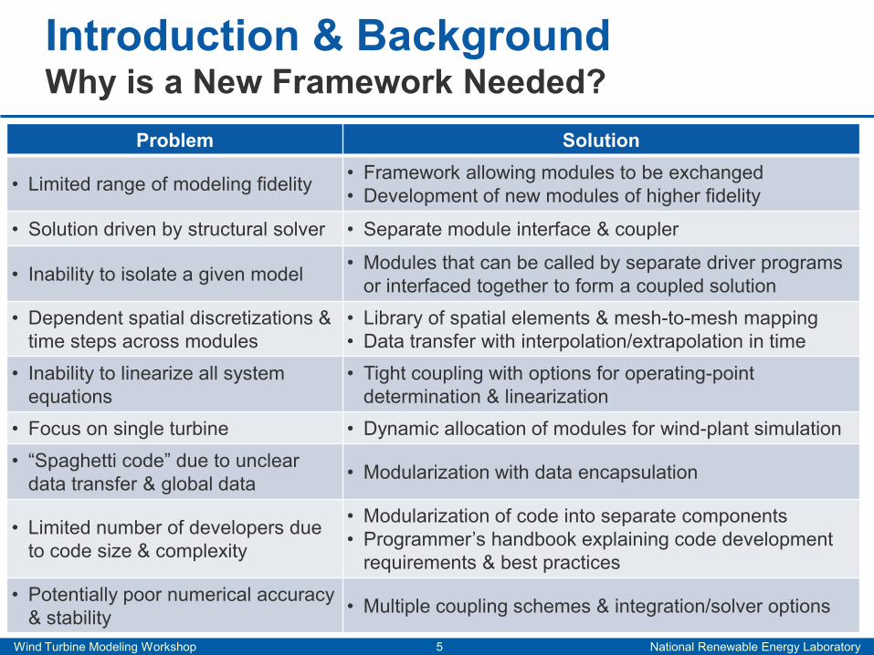
Introduction & Background Why is a New Framework Needed?
Wind Turbine Modeling Workshop 6 National Renewable Energy Laboratory
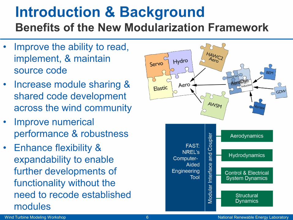
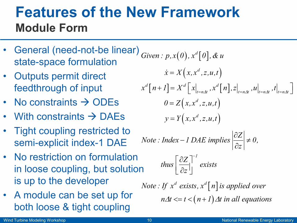
• Improve the ability to read, implement, & maintain source code
• Increase module sharing & shared code development across the wind community
• Improve numerical performance & robustness
• Enhance flexibility & expandability to enable further developments of functionality without the need to recode established modules
Introduction & Background Benefits of the New Modularization Framework
Wind Turbine Modeling Workshop 7 National Renewable Energy Laboratory
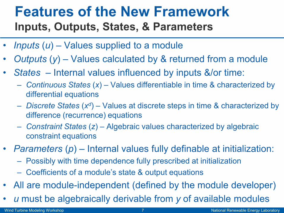
• Inputs (u) – Values supplied to a module • Outputs (y) – Values calculated by & returned from a module • States – Internal values influenced by inputs &/or time:
– Continuous States (x) – Values differentiable in time & characterized by differential equations
– Discrete States (xd) – Values at discrete steps in time & characterized by difference (recurrence) equations
– Constraint States (z) – Algebraic values characterized by algebraic constraint equations
• Parameters (p) – Internal values fully definable at initialization: – Possibly with time dependence fully prescribed at initialization – Coefficients of a module’s state & output equations
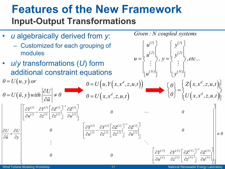
• All are module-independent (defined by the module developer) • u must be algebraically derivable from y of available modules
Features of the New Framework Inputs, Outputs, States, & Parameters
Wind Turbine Modeling Workshop 8 National Renewable Energy Laboratory
Wind Turbine Modeling Workshop 13 National Renewable Energy Laboratory
• Time marching about initial conditions (ICs) (loose & tight) • Operating-point (OP) determination (tight only):
– Static equilibrium – Steady state – Periodic steady state – With or without trim of inputs
• Linearization (tight only): – Formed from Jacobians – Linearization about given ICs,
given time, or OP – Useful for modal analysis,
controls design, & stability analysis
• OP & linearization not available in loose coupling due to more general formulation allowed
Features of the New Framework Time Marching, OP Determination & Linearization
[ ] [ ]d d
d dx dd d dut n t t n t
d d
x A x A x B ux n 1 A x A x n B u
y C x C x D u∆ ∆
∆ ∆ ∆ ∆∆ ∆ ∆ ∆
∆ ∆ ∆ ∆= =
= + ++ = + +
= + +
1
op
X X Z ZA ,etc...x z z x
− ∂ ∂ ∂ ∂ = − ∂ ∂ ∂ ∂
Wind Turbine Modeling Workshop 14 National Renewable Energy Laboratory
( ) ( ) ( ) ( )
( ) ( ) ( ) ( )
( ) ( ) ( ) ( )
1 d 1 1 1
2 d 2 2 2
N d N N N
X , X , Z ,Y
X , X , Z ,YU
X , X , Z ,Y
y
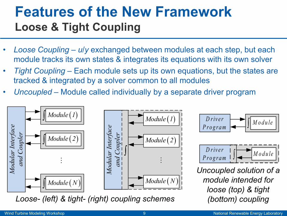
• Loose coupling: – Interconnects individual modules – Derives u from y (algebraically):
• Including mesh-to-mesh mapping • Including interpolation/extrapolation
in time – Drives overall solution forward
• Tight coupling (all above, plus): – Integrates the coupled system
equations using one of its own solvers
– Drives the OP & linearization calculations
• Modules link through the glue code • Submodules can be linked with
each other if & only if they collectively act as one module
Features of the New Framework Module Interface & Coupler (AKA “Glue Code”)
Coupled system (left), effective tightly coupled system (top right), & effective coupled linear system (bottom right)
d ZX ,X , ,Y
U
y
d
dx dd du
d
u
A,A ,B,A , A ,B ,
C,C ,D
y
∆
∆
Wind Turbine Modeling Workshop 15 National Renewable Energy Laboratory
• Data encapsulation: – No global data – Data structures for u, y, x, xd, z, & p
defined in a module – Data stored in the driver program &
passed to the module through subroutine arguments
• Consequences: – No module can access the states or
parameters of another module: • Clear data transfer • u can only be derived from y
– Dynamic allocation: • Multiple instances of a module can
exist simultaneously
Features of the New Framework Data Encapsulation & Dynamic Allocation
Example SOWFA Simulation
From One Blade to an Entire Rotor
Wind Turbine Modeling Workshop 16 National Renewable Energy Laboratory
• Save/retrieve capability: – Save all data, write to a file, retrieve
later, & continue simulating from that point
• The new framework also establishes a basis for: – Mixed-language programming – Multicore processing – Co-simulation across a network – Hiding the details of individual model
components to protect intellectual property (IP)
– Hardware-in-the-loop (HIL) simulation
Features of the New Framework Other Features
CAE Tools
Test Data Computational Solutions
Theory
Wind Turbine Modeling Workshop 17 National Renewable Energy Laboratory
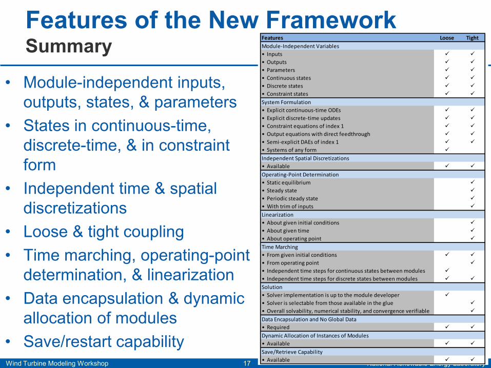
• States in continuous-time, discrete-time, & in constraint form
• Independent time & spatial discretizations
• Loose & tight coupling • Time marching, operating-point
determination, & linearization • Data encapsulation & dynamic
allocation of modules • Save/restart capability
Features of the New Framework Summary Features Loose Tight
Module-Independent Variables• Inputs • Outputs • Parameters • Continuous states • Discrete states • Constraint states
System Formulation• Explicit continuous-time ODEs • Explicit discrete-time updates • Constraint equations of index 1 • Output equations with direct feedthrough • Semi-explicit DAEs of index 1 • Systems of any form
Independent Spatial Discretizations• Available
Operating-Point Determination• Static equilibrium • Steady state • Periodic steady state • With trim of inputs
Linearization• About given initial conditions • About given time • About operating point
Time Marching• From given initial conditions • From operating point • Independent time steps for continuous states between modules • Independent time steps for discrete states between modules
Solution• Solver implementation is up to the module developer • Solver is selectable from those available in the glue • Overall solvability, numerical stability, and convergence verifiable
Data Encapsulation and No Global Data• Required
Dynamic Allocation of Instances of Modules• Available
Save/Retrieve Capability• Available
Wind Turbine Modeling Workshop 18 National Renewable Energy Laboratory
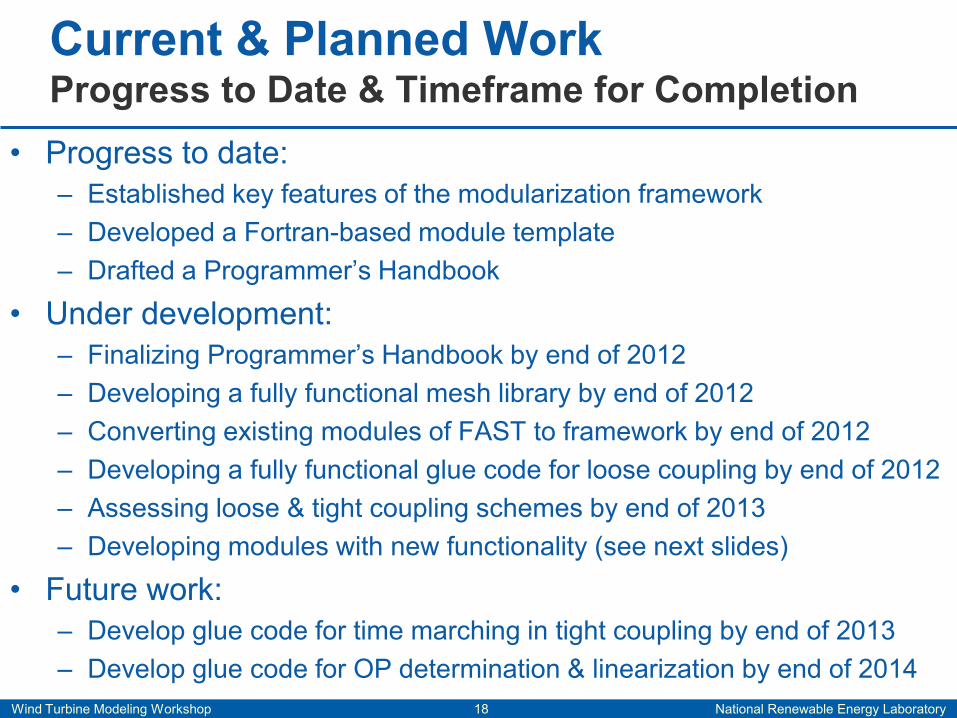
• Progress to date: – Established key features of the modularization framework – Developed a Fortran-based module template – Drafted a Programmer’s Handbook
• Under development: – Finalizing Programmer’s Handbook by end of 2012 – Developing a fully functional mesh library by end of 2012 – Converting existing modules of FAST to framework by end of 2012 – Developing a fully functional glue code for loose coupling by end of 2012 – Assessing loose & tight coupling schemes by end of 2013 – Developing modules with new functionality (see next slides)
• Future work: – Develop glue code for time marching in tight coupling by end of 2013 – Develop glue code for OP determination & linearization by end of 2014
Current & Planned Work Progress to Date & Timeframe for Completion
Wind Turbine Modeling Workshop 19 National Renewable Energy Laboratory
Current & Planned Work New Modules Under Development
NREL is a national laboratory of the U.S. Department of Energy, Office of Energy Efficiency and Renewable Energy, operated by the Alliance for Sustainable Energy, LLC.