Studies: A) Results from ARIES-IFE Study B) Plans For Compact Stellarator Farrokh Najmabadi US/Japan Workshop October 9-11, 2003 UC San Diego Electronic copy: http://aries.ucsd.edu/najmabadi/TALKS ARIES Web Site: http://aries.ucsd.edu/ARIES
Transcript
Overview of US Power Plant Studies:A) Results from ARIES-IFE StudyB) Plans For Compact Stellarator
ARIES Program charter was expanded in FY00 to include both IFE and MFE concepts
ARIES activities in FY03:
ARIES-IFE study was continued for another year (~50% of the effort): The ARIES-IFE study is now officially completed. Work in FY03 was focused on thick-liquid wall concept (i.e.,
HYLIFE) Results from 2001 and 2002 research will appear in Journal of
Fusion Science & Technology (pre-prints available on ARIES Web site).
ARIES compact stellarator (ARIES-CS) was started (~50% of effort) This is a three-years study All of ARIES Team effort will be devoted to ARIES-CS in FY04.
Selected Results from ARIES-IFE Studies
(Laser-Driven Direct-Drive Systems)
Objectives:
Analyze & assess integrated and self-consistent IFE chamber concepts
Understand trade-offs and identify design windows for promising concepts. The research is not aimed at developing a point design.
Approach:
Six classes of target were identified. Advanced target designs from NRL (laser-driven direct drive) and LLNL (Heavy-ion-driven indirect-drive) are used as references.
To make progress, we divided the activity based on three classes of chambers:• Dry wall chambers;• Solid wall chambers protected with a “sacrificial zone” (such as liquid
films); • Thick liquid walls.
We research these classes of chambers in series with the entire team focusing on each.
ARIES Integrated IFE Chamber Analysis and Assessment Research Is An Exploration Study
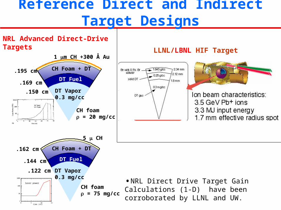
NRL Advanced Direct-Drive Targets
DT Vapor0.3 mg/cc
DT Fuel
CH Foam + DT
1 m CH +300 Å Au
.195 cm
.150 cm
.169 cm
CH foam = 20 mg/cc
DT Vapor0.3 mg/cc
DT Fuel
CH Foam + DT
5 CH
.122 cm
.144 cm
.162 cm
CH foam = 75 mg/cc
1
10
100
1000
0 5 10 15time (ns)
laser power •NRL Direct Drive Target Gain Calculations (1-D) have been corroborated by LLNL and UW.
LLNL/LBNL HIF Target
Reference Direct and Indirect Target Designs
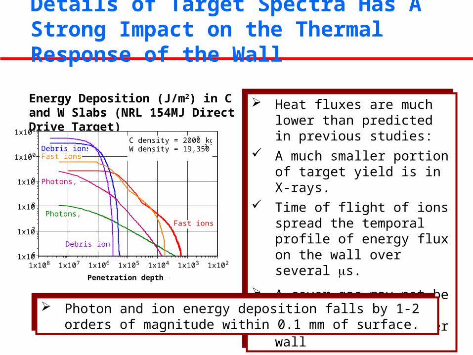
Details of Target Spectra Has A Strong Impact on the Thermal Response of the Wall
Energy Deposition (J/m2) in C and W Slabs (NRL 154MJ Direct Drive Target)
1x10⁶
1x10⁷
1x10⁸
1x10⁹
1x10¹⁰
1x10¹¹
1x10⁻⁸ 1x10⁻⁷ 1x10⁻⁶ 1x10⁻⁵ 1x10⁻⁴ 1x10⁻³ 1x10⁻²
Debris ions,W
Fast ions, C
Photons, W
Photons, C
Fast ions, W
En
ergy
dep
osit
ion
(J/
m3 )
Penetration depth (m)
Debris ions, CC density = 2000 kg/m3
W density = 19,350 kg/m3
Heat fluxes are much lower than predicted in previous studies:
A much smaller portion of target yield is in X-rays.
Time of flight of ions spread the temporal profile of energy flux on the wall over several s.
A cover gas may not be necessary for protecting the chamber wall
Heat fluxes are much lower than predicted in previous studies:
A much smaller portion of target yield is in X-rays.
Time of flight of ions spread the temporal profile of energy flux on the wall over several s.
A cover gas may not be necessary for protecting the chamber wall
Photon and ion energy deposition falls by 1-2 orders of magnitude within 0.1 mm of surface.
Photon and ion energy deposition falls by 1-2 orders of magnitude within 0.1 mm of surface.
Dry Wall Concepts
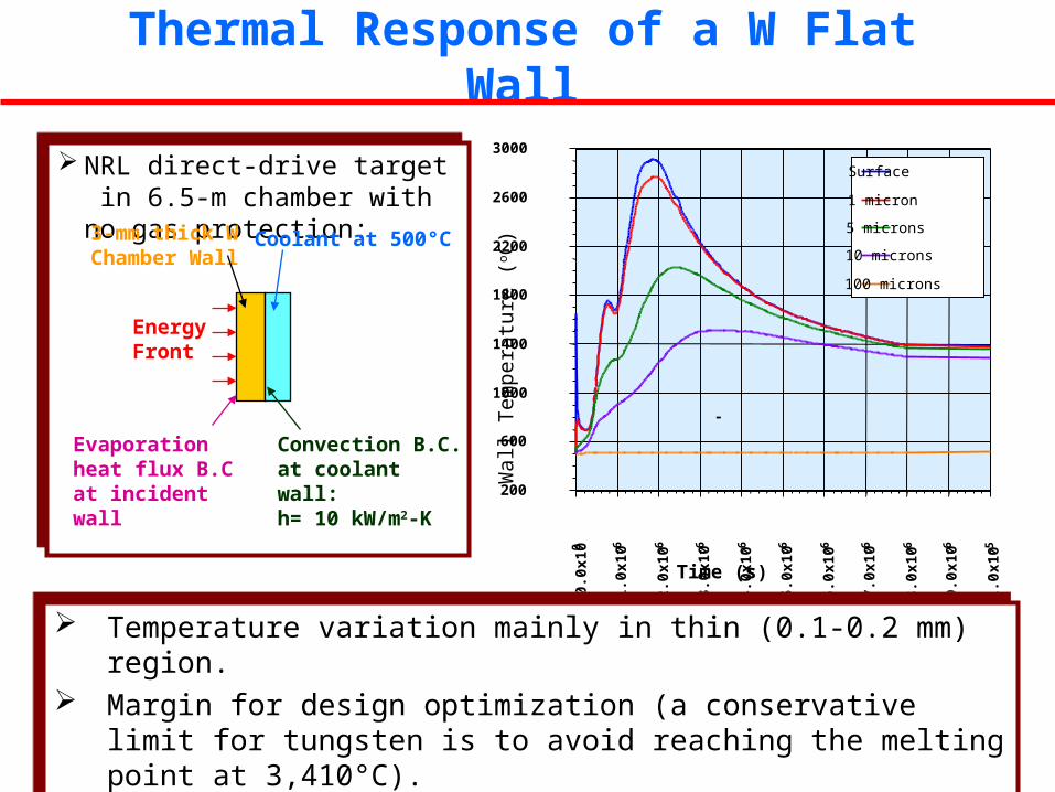
Thermal Response of a W Flat Wall
NRL direct-drive target in 6.5-m chamber with no gas protection:
NRL direct-drive target in 6.5-m chamber with no gas protection:
Coolant at 500°C3-mm thick W Chamber Wall
EnergyFront
Evaporation heat flux B.C at incident wall
Convection B.C. at coolant wall:h= 10 kW/m2-K 200
600
1000
1400
1800
2200
2600
3000
0.0x
100
1.0x
10-6
2.0x
10-6
3.0x
10-6
4.0x
10-6
5.0x
10-6
6.0x
10-6
7.0x
10-6
8.0x
10-6
9.0x
10-6
1.0x
10-5
Surface
1 micron
5 microns
10 microns
100 microns
Time (s)
-
Wal
l Tem
pera
ture
(o C
)
Temperature variation mainly in thin (0.1-0.2 mm) region. Margin for design optimization (a conservative limit for tungsten is to avoid
reaching the melting point at 3,410°C). Similar margin for C slab.
Temperature variation mainly in thin (0.1-0.2 mm) region. Margin for design optimization (a conservative limit for tungsten is to avoid
reaching the melting point at 3,410°C). Similar margin for C slab.
Depth (mm): 0 0.021 3
Typical T Swing (°C): ~1000 ~300 ~10~1
Coolant
~ 0.2 mm Armor
3-5 mmStructural Material
Most of neutrons deposited in the back where blanket and coolant temperature will be at quasi steady state due to thermal capacity effect
Blanket design can be adapted from MFE blankets
Significant high-energy ion flux on the armor.
Photon and ion energy deposition falls by 1-2 orders of magnitude within 0.1-0.2 mm of surface.
Beyond the first 0.1-0.2 mm of the surface. First wall experiences a much more uniform q’’ and quasi steady-state temperature (heat fluxes similar to MFE).
Use an Armor Armor optimized to handle particle and heat flux. First wall is optimized for efficient heat removal.
All the Action Takes Place within 0.1-0.2 mm of Surface -- Use an Armor
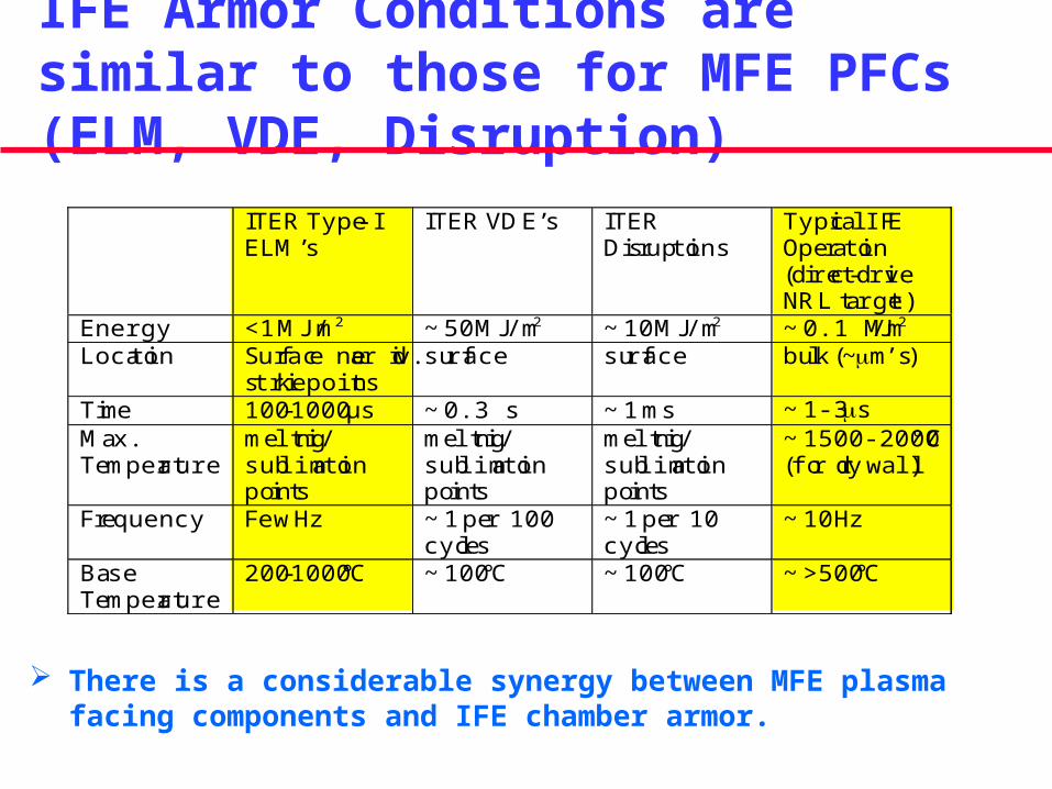
IFE Armor Conditions are similar to those for MFE PFCs (ELM, VDE, Disruption)
There is a considerable synergy between MFE plasma facing components and IFE chamber armor.
ITER Type-IELM’s
ITER VDE’s ITERDisruptions
Typical IFEOperation(direct-driveNRL target)
Energy <1 MJ/m2 ~ 50 MJ/m2 ~ 10 MJ/m2 ~ 0.1 MJ/m2
Location Surface near div.strike points
surface surface bulk (~m’s)
Time 100-1000 µs ~ 0.3 s ~ 1 ms ~ 1-3 sMax.Temperature
melting/sublimationpoints
melting/sublimationpoints
melting/sublimationpoints
~ 1500-2000°C(for dry wall)
Frequency Few Hz ~ 1 per 100cycles
~ 1 per 10cycles
~ 10 Hz
BaseTemperature
200-1000°C ~ 100°C ~ 100°C ~ >500°C
Direct-drive targets (initial T=18K) are heated during their travel in the chamber by:
Friction with the chamber gas (mainly through condensation heat flux) requiring Lower gas pressure Slower injection velocity
Radiation heat flux from hot first wall, requiring Lower equilibrium temperature Faster injection velocity
Addition of a thin (~70m) foam improves the thermal response considerably.
Target injection Design Window Naturally Leads to Certain Research Directions
1x101
1x10²
1x10³
1x10⁴
1x10⁵
1x10⁶
0.1 1 10 100
1000K, 400m/s
4000K,400m/s
1000K, 100 m/s
4000K,100m/s
Max. heat flux is at the leading target surface
Xe temp.,Inj.vel.
Condensation coefficient x Pressure at RT (mtorr) (c x P)
q''max for D -T to
reach triple pointfor Rchamb of 6 m
and injection vel. of: 400 m/s
100 m/s
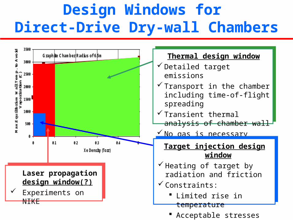
Design Windows for Direct-Drive Dry-wall Chambers
Thermal design window Detailed target emissions Transport in the chamber including
time-of-flight spreading Transient thermal analysis of
chamber wall No gas is necessary
Laser propagation design window(?)
Experiments on NIKE
Target injection design window Heating of target by radiation and
friction Constraints:
Limited rise in temperature Acceptable stresses in DT ice
Wetted-Wall Concepts
A renewable thin-liquid protection resolve several issues: It can handle a much higher heat fluxes compared to solid surfaces; It will eliminate damage to the armor/first wall due to high-energy ions.
A renewable thin-liquid protection resolve several issues: It can handle a much higher heat fluxes compared to solid surfaces; It will eliminate damage to the armor/first wall due to high-energy ions.
Aerosol Generation and Transport is the Key Issue for Thin-Liquid Wall Concepts
A renewable thin-liquid protection, however, introduces its own critical issues: Fluid-dynamics aspects (establishment and maintenance of the film)
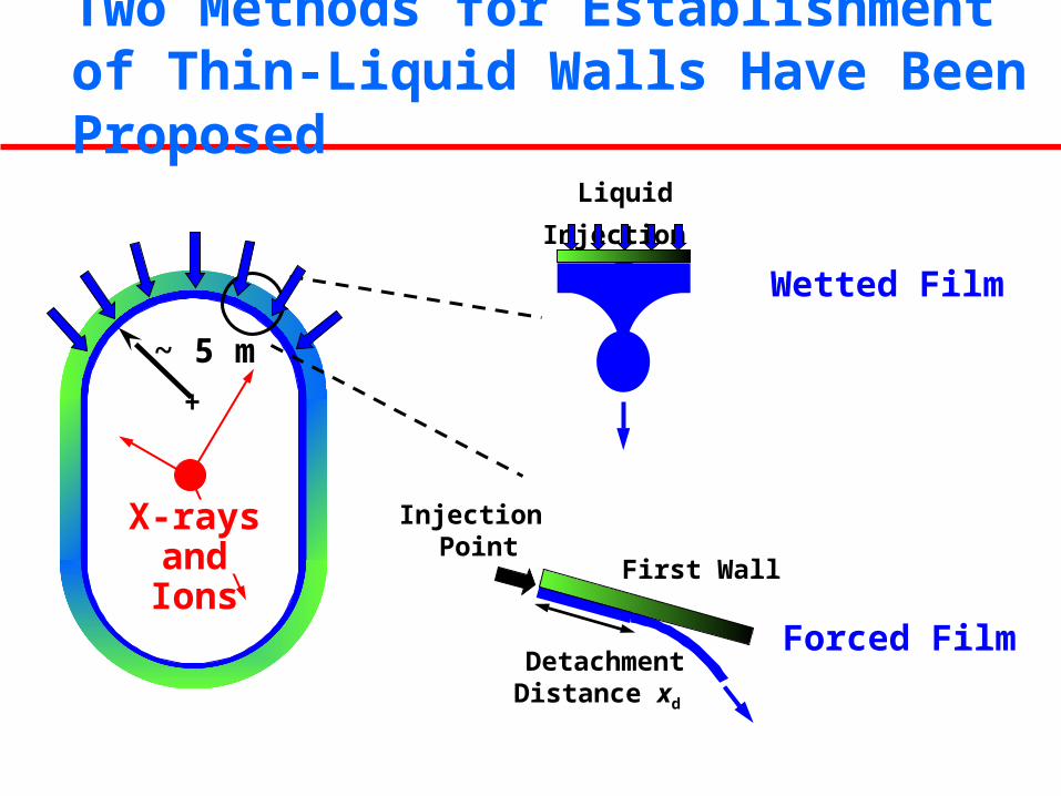
“Wetted wall:” Low-speed normal injection through a porous surface “Forced film:” High-speed tangential injection along a solid surface
Chamber clearing (recondensation of evaporated liquid) “Source term:” both vapor and liquid (e.g., explosive boiling) are ejected Super-saturated state of the chamber leads to aerosol generation Target injection and laser beam propagation lead to sever constraints on
the acceptable amount and size of aerosol in the chamber.
A renewable thin-liquid protection, however, introduces its own critical issues: Fluid-dynamics aspects (establishment and maintenance of the film)
“Wetted wall:” Low-speed normal injection through a porous surface “Forced film:” High-speed tangential injection along a solid surface
Chamber clearing (recondensation of evaporated liquid) “Source term:” both vapor and liquid (e.g., explosive boiling) are ejected Super-saturated state of the chamber leads to aerosol generation Target injection and laser beam propagation lead to sever constraints on
the acceptable amount and size of aerosol in the chamber.
Two Methods for Establishment of Thin-Liquid Walls Have Been Proposed
X-rays and Ions
~ 5 m
Forced Film
First Wall
Injection Point
DetachmentDistance xd
Liquid Injection
Wetted Film
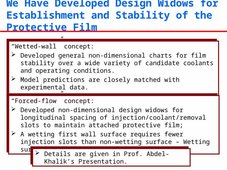
“Wetted-wall” concept: Developed general non-dimensional charts for film stability over a wide
variety of candidate coolants and operating conditions. Model predictions are closely matched with experimental data. It will eliminate damage to the armor/first wall due to high-energy ions.
“Wetted-wall” concept: Developed general non-dimensional charts for film stability over a wide
variety of candidate coolants and operating conditions. Model predictions are closely matched with experimental data. It will eliminate damage to the armor/first wall due to high-energy ions.
We Have Developed Design Widows for Establishment and Stability of the Protective Film
“Forced-flow” concept: Developed non-dimensional design widows for longitudinal spacing of
injection/coolant/removal slots to maintain attached protective film; A wetting first wall surface requires fewer injection slots than non-wetting
surface – Wetting surfaces are more desirable.
“Forced-flow” concept: Developed non-dimensional design widows for longitudinal spacing of
injection/coolant/removal slots to maintain attached protective film; A wetting first wall surface requires fewer injection slots than non-wetting
surface – Wetting surfaces are more desirable.
Details are given in Prof. Abdel-Khalik’s Presentation. Details are given in Prof. Abdel-Khalik’s Presentation.
FLiBe aerosol and vapor mass history in a 6.5-m radius following a target explosion (ablated thickness of 5.5 mm)
Most of ablated material remains in the chamber in aerosol form; Only homogeneous nucleation and growth from the vapor phase.
FLiBe aerosol and vapor mass history in a 6.5-m radius following a target explosion (ablated thickness of 5.5 mm)
Most of ablated material remains in the chamber in aerosol form; Only homogeneous nucleation and growth from the vapor phase.
Most of Ablated Material Would Be in The Form of Aerosol
There Are Many Mechanism of Aerosol Generation in an IFE Chamber
Details are given in Dr. Tillack’s Presentation. Details are given in Dr. Tillack’s Presentation.
Homogeneous nucleation and growth from the vapor phase Supersaturated vapor Ion seeded vapor
Phase decomposition from the liquid phase Thermally driven phase explosion Pressure driven fracture
Hydrodynamic droplet formation (May be critical in Thick-liquid Wall Concepts”)
Homogeneous nucleation and growth from the vapor phase Supersaturated vapor Ion seeded vapor
Phase decomposition from the liquid phase Thermally driven phase explosion Pressure driven fracture
Hydrodynamic droplet formation (May be critical in Thick-liquid Wall Concepts”)
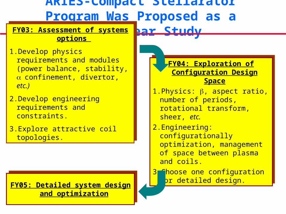
ARIES Research Plans for FY03-FY05
We Have Initiated a Three-Years Study of Compact Stellarators as Power Plants
Initiation of NCSX and QSX experiments in US; Successful operation of LHD in Japan and construction of W7X in Germany;
Review committees have asked for assessment of compact stellarator option as a power plant; Similar interest has been expressed by national stellarator program.
Such a study will advance physics and technology of compact stellarator concept and addresses concept attractiveness issues that are best addressed in the context of power plant studies.
NCSX and QSX plasma/coil configurations are optimized for most flexibility for scientific investigations. Optimum plasma/coil configuration for a power plant may be different. Identification of such optimum configuration will help compact stellarator research program.
ARIES-Compact Stellarator Program Was Proposed as a Three-year Study