OWNERS AND SERVICE MANUAL INNOVATIVE CONCEPTS IN ENTERTAINMENT INC. 10123 MAIN STREET, CLARENCE, NY 14031 SERVICE: 1-716-759-0360 FAX: 1-716-759-0884 E-MAIL: [email protected]WEBSITE: www.icegame.com
Transcript
1
OWNERS AND SERVICE MANUAL INNOVATIVE CONCEPTS IN ENTERTAINMENT INC.
10123 MAIN STREET, CLARENCE, NY 14031 SERVICE: 1-716-759-0360
TABLE OF CONTENTS Safety and Warnings 4 Setup Game Play 5 Game Setup Volume Controls Programming See Insert Service Marquee Bulb replacement 7 Lower Illumination replacement 8 Upper Illumination replacement 9 Power Supply Replacement 10 Horizontal Control Replacement 11 Tilt Control Replacement 12 Computer and I/O replacement 13 Upper monitor assembly replacement 14 Assembly Diagrams Main cabinet components 15 & 16 Wiring Diagrams See insert Spare Parts 17 Warranty 18
REVISION Alpha 3-9-2010
4
BEFORE YOU BEGIN
WARNING: WHEN INSTALLING THIS GAME, A GROUNDED A.C. RECEPTACLE MUST BE USED. FAILURE TO DO SO COULD RESULT IN INJURY TO YOURSELF OR OTHERS. FAILURE TO USE A GROUNDED RE-CEPTACLE COULD ALSO CAUSE IMPROPER GAME OPERATION, OR DAMAGE TO THE ELECTRONICS. DO NOT DEFEAT OR REMOVE THE GROUNDING PRONG ON THE POWER CORD FOR THE SAME REA-SON AS GIVEN ABOVE. USING AN IMPROPERLY GROUNDED GAME COULD VOID YOUR WARRANTY. HAVE A QUALIFIED ELECTRICIAN CHECK YOUR A.C. RECEPTACLE TO BE SURE THE GROUND IS FUNC-TIONING PROPERLY. DO NOT WASH YOUR GAME WITH A PRESSURE WASHER.
AVERTISSEMENT: lors de l'installation de ce jeu, la terre AC récipient doit être utilisé. Ne pas le faire pourrait en-traîner un préjudice à vous ou à d'autres. Le non-recours à la terre récipient pourrait également causer une mau-vaise opération de jeu, ou les dommages causés à l'électronique. NE PAS détériorer ou de retirer la broche de terre sur le cordon d'alimentation pour la même raison, comme indiqué ci-dessus. Indûment l'aide d'un jeu de la terre pourrait annuler votre garantie. Ont un électricien qualifié de vérifier votre récipient AC pour s'assurer que le sol fonctionne correctement. Ne lavez pas votre jeu avec une laveuse à pression.
INSTALLATION The game comes ready to play with just a few simple things to keep in mind. 1. Plug the game into the A.C. outlet and turn on power to the game. The switch for the game is located on a
power module on the outside rear of the game. THIS GAME IS DESIGNED TO DISSIPATE STATIC ELECTRICITY THROUGH THE GROUNDING PLANE OF THE GAME. IF THE A.C. GROUND DOES NOT WORK, THE GAME COULD DISCHARGE STATIC ELECTRICITY THROUGH THE GAME CIRCUITRY, WHICH COULD CAUSE DAMAGE. 2. Make sure the game is level after installation. It is necessary to make sure the game is level for safety
concerns. 3. Check that the A.C. voltage rating on the back of the game matches the A.C. voltage of your location.
THE POWER SUPPLY IS NOT VOLTAGE ADJUSTABLE. TO OPERATE THE GAME AT VOLTAGES OTHER THAN THOSE IT WAS DESIGNED FOR. PLEASE CONTACT OUR SERVICE DEPARTMENT FOR VOLTAGE CONVERSION INFORMATION.
WARNING
DO NOT remove any of the components on the main board (e.g. compact flash and eproms) while the game is powered on. This may cause permanent damage to the parts and the main board. Re-moving any main board component part while powered on will void the warranty. Ne retirez pas l'un des composants sur la carte principale (par exemple Compact Flash et EPROMs), tandis que le jeu est sous tension. Cette mai causer des dommages permanents aux parties et la carte principale. Suppression de tout bord principal élément sous tension alors que an-nulera la garantie. NOTE: THIS GAME IS INTENDED FOR INDOOR USE ONLY. ON THE BACK PANEL OF THE GAME: WARNING: SHOCK HAZARD - DO NOT OPEN. REFER SERVICING TO SERVICE PERSONNEL. REMARQUE: CE JEU EST DESTINÉ POUR USAGE À L'INTÉRIEUR SEULEMENT. SUR LE PANNEAU ARRIÈRE DU JEU: AVERTISSEMENT: RISQUE DE CHOC - NE PAS OU-VRIR. RÉPARATION À UN PERSONNEL DE SERVICE.
SAFETY AND WARNINGS
5
SETUP - INTRODUCTION
Game Play: “Welcome to the Bloks Party!” To win the game, stack nine blocks to get the big bo-nus. Drop three bloks and the game is over….. In this game the player attempts to stack nine bloks. As the bloks stack up the player reaches new win zones until the fi-nal zone is reached. If the player drops three bloks the player wins that zone’s tickets and the game is over. Setup: Your game is shipped with the marquee folded down. Position the marquee back to a up right position by lifting the marquee from the back. Insert one washer and 1/4-20 bolt to each side of the marquee and tighten all four bolts. See diagram below.
6
SETUP - ASSEMBLY
METERS LOCATION The meters are located through the coin door. Both coin and ticket meters can be found there. CHANGING THE VOLUME LEVELS DURING PLAY There are UP and DOWN buttons located in the coin door. Pressing of these buttons will either increase the volume level or decrease the level volume. ADDING A TEST CREDIT WITHOUT ADVANCING THE COIN METER
Pressing the “TEST” button located in the coin door will add one credit to the game without advancing the coin meter.
ACCESSING PROGRAMMING Press the button “DIAG” located in the coin door to enter programming. PROGRAMMING
To navigate through the menus, press the “UP” and “DOWN” buttons to move up and down in the menus or to increase or decrease the values of each option. Press the “DIAG” button to select the desired menu or the option to change. PROGRAM OPTIONS
See insert for latest program options.
7
SERVICE CAUTION This game uses complex electronic components that are very sensitive to static electricity. Observe precau-tions below before handling these electronics. Failure to do so may void the warranty and damage electronic assemblies.
Before servicing electronics, turn off AC power to the game. Wait for capacitors to discharge.
DO NOT remove any of the components on the main board (e.g. compact flash and eproms) while the game is powered on. This may cause permanent damage to the parts and the main board.
Before touching or handling electronic assemblies, discharge static electricity on your body. To discharge this static, begin by connecting the line cord to a grounded outlet. Don’t turn on the game. Next, touch the safety ground stud of the power supply chassis.
Store electronic assemblies in an anti-static area. Use anti-static bags to store or transport the game circuit boards.
Don’t remove or connect electronic assemblies when cabinet power is on. Otherwise, you’ll damage electronic as-semblies and void the game’s warranty.
After you complete maintenance or service, replace ground wires, shields, safety covers and install and tighten ground and mounting screw.
MARQUEE BULB REPLACEMENT Remove the front panel of the marquee by removing the four 1/4-20 bolts. Press the red button on the socket to release the bulb and remove the retaining clip (BW2017) as shown below. Replace the bulbs with ICE part number 8312. Be sure to reinstall the bulb clip (BW2017) when replacing the bulb or the bulb will not stay installed in light socket! Replace the front graphic panel and reinstall the four 1/4-20 bolts.
8
SERVICE LOWER ILLUMINATION REPLACEMENT Remove the five 1/4-20 bolts that hold the sides of the lower cabinet assembly on. Once removed you will find two blue CFL 24w bulbs (ICE Part E00272) and one yellow CFL 24w bulb (ICE Part E00273). The diagram below only shows the left side, repeat the same on the right side to access the right side bulbs.
9
SERVICE UPPER ILLUMINATION REPLACEMENT LED strips provide the lighting in each of the front BLOKSs and are very reliable. Before replacing strips, test for 12 volts DC to eliminate wiring or logical board failures. To access these strips you will need to remove the seven screws that hold the plastic bloks assembly to the front of the cabinet. There is one on each side of the cabinet. The metal housing is held on by two 8-32 screws. You will need to gain access to the back of the metal housing to disconnect each LED Strip Assembly.Each strip assembly is attached to the metal housing by double sided tape. This tape is found on the back of the new strip assembly and to remove the old assembly, you will need to scrape the strip clean off the metal. Be careful not to take any of the white paint off the metal work. Be sure to clean the surface before applying the new strip assembly. There is two strips per blok. The right side is shown below.
10
SERVICE POWER SUPPLY REPLACEMENT This game has one power supply that provides 24 VDC to the monitor. The game’s I/O board uses the PC’s built in power supply for power. To access the monitor’s power supply, open the bottom back panel. Remove the four 1/4-20 bolts shown below to remove the upper back panel. You will need to disconnect the AC harness that is connected to the cooling fans. The ICE part number for the 24VDC supply is MON42/47PS. It is important to check the function of the cooling fans located on the upper back panel. These fans will push out the heat that will collect at the top of the game. It is recommended to replace noisy or slow moving fans.
11
SERVICE HORIZONTAL CONTROL REPLACEMENT The game’s controller has two axis, horizontal and tilt. If the game has no movement horizontally when the controller is pushed to either side, you will need to check the horizontal pot located at the back of the game. If the game has no tilt control when you move the controller handle left and right, you will need to check the tilt pot located at the front of the controller handle. See next page for in-structions. To access the horizontal pot, remove the lower back panel shown below. Check for the presence of +5 VDC on the outsides of the pot (One pin will have +5VDC and the other Ground). The inside pin should vary in voltage when the controller is pushed left and right. If no voltage is found on the out-side pins, check the wiring and I/O board for failure. If voltage is present on the outside pins but no voltage is present at the center pin, replace the pot. If you have sporadic movement, perform a cali-bration from the setup menu before replacing the pot. If you do replace the pot you will also need to perform a calibration from the menu before resuming use of your game. Be sure when replacing the horizontal pot that the pot’s movement is centered so that full travel can be achieved both left and right. In other words, center the pot, center the controller, then engage the teeth of the gears. Failure to do so will damage the replacement pot.
12
SERVICE TILT CONTROL REPLACEMENT The game’s controller has two axis, horizontal and tilt. If the game has no movement horizontally when the controller is pushed to either side, you will need to check the horizontal pot located at the back of the game. See previous page for details. If the game has no tilt control when you move the controller handle left and right, you will need to check the tilt pot located at the back of the controller handle. To access the tilt pot, remove the front two joint connectors shown below. Remove the first three controller rings to access the pot. Check for the presence of +5 VDC on two pins of the pot (One pin will have +5VDC and the other Ground). The last pin should vary in voltage when the controller handle is tilted left and right. If no voltage is found on two of the pins, check the wiring and I/O board for failure. If voltage is present on two of the pins but no voltage is present at the output pin, replace the pot. If you have sporadic movement, perform a calibration from the setup menu before replacing the pot. If you do replace the pot you will also need to perform a calibration from the menu before resuming use of your game. Be sure when replacing the tilt pot that the pot’s movement is centered so that full travel can be achieved both left and right. In other words, center the pot, center the controller, then engage the teeth of the gears. Failure to do so will damage the replacement pot.
13
SERVICE COMPUTER AND I/O CONTROL REPLACEMENT The computer is located on the back door itself. Two chains provides support to the back door when opened. Do not remove these chains for any reason. The computer is held on to the back door by two straps. Pushing the sides of the buckle will release the straps. Be sure that the straps are tight when finished.
14
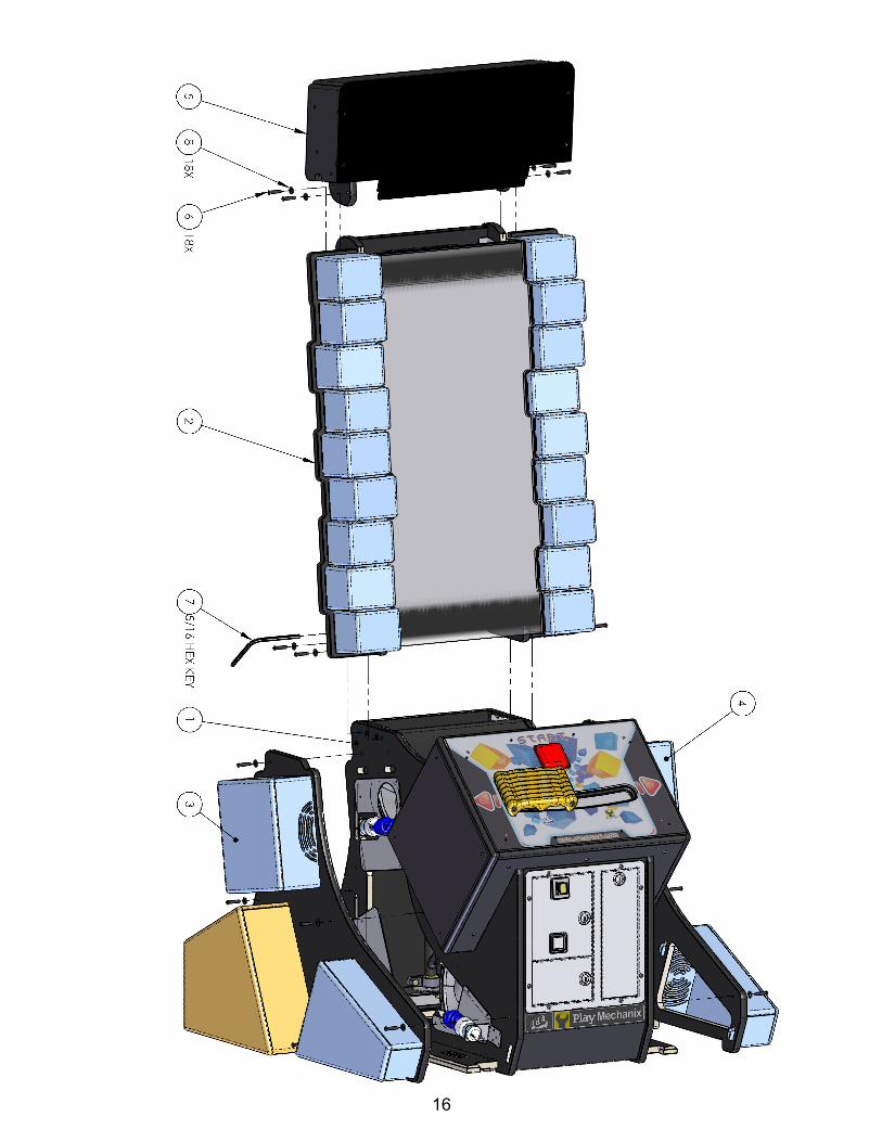
SERVICE UPPER MONITOR ASSEMBLY REMOVAL The upper cabinet and marquee can be removed if desired. It is recommended to have assistance when removing the upper cabinet. A special 5/16 Latch wrench tool is included with your game. Re-move the four bolts holding the upper assembly stable. Remove all wire connectors that attaches the upper cabinet to the lower cabinet. Insert latch wrench and turn clockwise. With an additional person lift upper cabinet assembly up and out.
15
16
17
Electronics BX2090X Restore Disc BX2000X Computer BX2014 Dongle BX2034X Main I/O board RIO BX2050HX Main harness BX2060LX Computer DC harness BX2063MX Main AC harness BX2069LX Computer power cord harness MON42LCD 42” LCD panel 2111 Solid state relay 8980 LED Bulb Red Cluster E27 BX2006 Mega Button BX2007X Power mod 6 AMP BX2051HX Door Harness BX2052MX Start button harness BX2061MX AC extension harness BX2062MX AC block Lights BX2068MX Start button Lamp AC BX2070LX Ground rear door harness BX2071LX Controller ground harness BX2072LX Cover panel ground harness BX2073LX Rear door extension ground BX3008 Square Button CG2027 Power cord 9’ 10” E00259BXX controller tilt pot E00260BXX Horizontal pot E00272 Bulb Blue E00273 Bulb Yellow HH5005CL Ticket Dispenser PE2007 6x9 speaker SH2130X Ceramic socket BA2063LX Monitor supply AC harness BX1030X Stacked LED blocks
Mechanic 213 T-Molding Black 25/32” BX1010-P802 Control Arm BX1051 Gear 28 tooth BX1052 Gear 297 tooth PC60601A Allen Wrench 5/32” BX3004 Pillow Block CX1055 S-Hook 1/4x1/4 HR1013 Chain for ticket door WA5001A7X Assembly triple coin door 6706 Steel Extension spring BX3020 Block stack DECALS BX7000 Side control panel decal BX7001 Ice/Playmechanix Logo BX7004 Ticket door decal BX7012 Control panel decal
Spare Parts
18
WARRANTY POLICY
I.C.E. Inc warrants all components in new machines to be free of defects in materials and workmanship for the period listed below: ■ 180 days on Main PCB’s, Computers & Motors ■ 1 year on all LCD monitor panels ■ 90 days on all other electronic and mechanical components
■ 30 days on all I.C.E. repairs and parts purchases I.C.E. Inc shall not be obligated to furnish a warranty request under the following conditions:
■ Equipment or parts have failed through normal wear and tear ■ Equipment has been subjected to unwarranted stress, abuse or neglect ■ Equipment has been damaged as a result of arbitrary repair/modification
Products will only be covered under warranty by obtaining an I.C.E. authorized RMA #. To obtain an RMA # please provide I.C.E. tech support with the game serial # or original I.C.E. invoice # and a detailed description of the failure or fault symptoms. I.C.E. Inc will assume no liability whatsoever for costs associated with labor or travel time to replace defective parts. All defective warranty covered components will be replaced with new or factory refurbished compo-nents equal to OEM specifications. I.C.E. Inc will cover domestic UPS ground, or comparable shipping costs during the warranty period. Interna-tional or expedited shipments are available for an additional charge. To obtain credit defective parts must be returned to I.C.E. Inc, at the customer’s expense, within 30 days. After 30 days a 15% re-stocking fee will apply to all returns.
ICE distributors are independent, privately owned and operated. In their judgment, they may sell parts and/or accessories other than those manufactured by I.C.E. Inc. We cannot be responsible for the quality, suitability or safety of any non-I.C.E. part or modification (including labor) that is performed by such a distributor.
Innovative Concepts in Entertainment 10123 Main St.