77
Conext™ Battery Monitor Owner’s Guide www.SEsolar.com

Copyright © 2014 Schneider Electric. All Rights Reserved. Microsoft and Excel are registered trademarks of Microsoft Corporation in the United States and/or other countries. All trademarks are owned by Schneider Electric Industries SAS or its affiliated companies.
Exclusion for Documentation
UNLESS SPECIFICALLY AGREED TO IN WRITING, SELLER
(A) MAKES NO WARRANTY AS TO THE ACCURACY, SUFFICIENCY OR SUITABILITY OF ANY TECHNICAL OR OTHER INFORMATION PROVIDED IN ITS MANUALS OR OTHER DOCUMENTATION;
(B) ASSUMES NO RESPONSIBILITY OR LIABILITY FOR LOSSES, DAMAGES, COSTS OR EXPENSES, WHETHER SPECIAL, DIRECT, INDIRECT, CONSEQUENTIAL OR INCIDENTAL, WHICH MIGHT ARISE OUT OF THE USE OF SUCH INFORMATION. THE USE OF ANY SUCH INFORMATION WILL BE ENTIRELY AT THE USER’S RISK; AND
(C) REMINDS YOU THAT IF THIS MANUAL IS IN ANY LANGUAGE OTHER THAN ENGLISH, ALTHOUGH STEPS HAVE BEEN TAKEN TO MAINTAIN THE ACCURACY OF THE TRANSLATION, THE ACCURACY CANNOT BE GUARANTEED. APPROVED CONTENT IS CONTAINED WITH THE ENGLISH LANGUAGE VERSION WHICH IS POSTED AT WWW.SCHNEIDER-ELECTRIC.COM.
Document Number: 975-0691-01-01 Revision: Revision B Date: May 2014
Product Part Number: 865-1080-01
Contact Information www.SEsolar.com
For country details please contact your local Schneider Electric Sales Representative or visit the Schneider Electric website at:
http://www.sesolar.com/where-to-buy/
Information About Your System
As soon as you open your product, record the following information and be sure to keep your proof of purchase.
Serial Number _________________________________
Product Number _________________________________
Purchased From _________________________________
Purchase Date _________________________________

975-0691-01-01 Revision B i
About This Guide
Purpose
The purpose of this Owner’s Guide is to provide explanations and procedures for
installing, operating, configuring, maintaining, and troubleshooting the Conext
Battery Monitor.
Scope
The Guide provides safety guidelines, planning, and setup information,
procedures for installing the Battery Monitor, as well as information about
configuring, monitoring, and troubleshooting the unit.
Audience
The Guide is intended for use by anyone who plans to construct, install, or
operate a system which includes the Battery Monitor. Certain configuration tasks
should only be performed by qualified personnel in consultation with your battery
manufacturer or system designer. Electrical equipment should be installed,
operated, serviced, and maintained only by qualified personnel. Servicing of
batteries must only be performed or supervised by qualified personnel with
knowledge of batteries and their required precautions. Qualified personnel have
training, knowledge, and experience in:
• Installing electrical equipment
• Applying applicable installation codes
• Analyzing and reducing the hazards involved in performing electrical work
• Installing and configuring batteries
• Selecting and using Personal Protective Equipment (PPE)
No responsibility is assumed by Schneider Electric for any consequences arising
out of the use of this material.
Organization
This Guide is organized into five chapters and an appendix.
Chapter 1, “Overview”, describes physical features of the Battery Monitor and
introduces the user interface.
Chapter 2, “Installation”, describes how to install, wire, and connect the Battery
Monitor to your network.
Chapter 3, “Configuration”, describes how to configure and change device
settings and upgrade firmware.
Chapter 4, “Monitoring”, describes how to monitor LCD indicator lights (LCDs)
and device levels.
Chapter 5, “Troubleshooting”, describes how to interpret events and alerts.
Appendix A, “Specifications”, contains the electrical, mechanical and
environmental specifications for the Battery Monitor.

About This Guide
ii 975-0691-01-01 Revision B
Conventions Used
The following conventions are used in this guide.
Abbreviations and Acronyms
Related Information
For more information about related products, refer to:
Conext Battery Monitor Quick Start Guide
Conext XW+ Inverter/Charger Owner’s Guide
Conext XW+ Inverter/Charger Installation Guide
Conext ComBox Owner’s Guide
Conext Configuration Tool Owner’s Guide
Conext AGS Owner’s Guide
Conext SCP Owner’s Guide
You can find more information about Schneider Electric as well as its products
and services at www.schneider-electric.com.
For specific information on Solar products go to www.SEsolar.com.
DANGER
DANGER indicates an imminently hazardous situation, which, if not avoided,
will result in death or serious injury.
WARNING
WARNING indicates a potentially hazardous situation, which, if not avoided,
can result in death or serious injury.
CAUTION
CAUTION indicates a potentially hazardous situation, which, if not avoided,
can result in moderate or minor injury.
NOTICE
NOTICE indicates important information that you need to read carefully.
BTS Battery Temperature Sensor
CEF Charge Efficiency Factor
CSA Canadian Standards Association
LCD Liquid Crystal Display
SOC State-of-charge
UL Underwriters Laboratories
VDC Volts DC

975-0691-01-01 Revision B iii
Important Safety Instructions
READ AND SAVE THESE INSTRUCTIONS - DO NOT DISCARD
This guide contains important safety instructions for the Conext Battery Monitor
that must be followed during installation and configuration procedures. Read and
keep this Installation Guide for future reference.
Read these instructions carefully and look at the equipment to become familiar
with the device before trying to install, operate, service or maintain it. The
following special messages may appear throughout this bulletin or on the
equipment to warn of potential hazards or to call attention to information that
clarifies or simplifies a procedure.
The addition of this symbol to a “Danger” or “Warning” safety label
indicates that an electrical hazard exists which will result in personal
injury if the instructions are not followed.
This is the safety alert symbol. It is used to alert you to potential
personal injury hazards. Obey all safety messages that follow this
symbol to avoid possible injury or death.
DANGER
HAZARD OF ELECTRIC SHOCK
• Read all instructions, cautionary markings, and all other appropriate
sections of this manual before installing, operating, troubleshooting or
performing maintenance on the Battery Monitor.
• Exercise extreme caution at all times to prevent accidents.
• These instructions are for use by qualified installers only.
Failure to follow these instructions will result in death or serious injury.

iv 975-0691-01-01 Revision B
DANGER
HAZARD OF ELECTRIC SHOCK AND FIRE
• Connect only to Safety Extra Low Voltage (SELV) circuits and power
sources.
• All wiring must be done by qualified personnel to ensure compliance with
all applicable installation codes and regulations.
• For Indoor Use Only. Install in a dry, indoor location away from direct
sunlight.
• To reduce the risk of electrical fire, replace fuses with same size, type, and
rating only.
• Do not disassemble. No user serviceable parts inside.
Failure to follow these instructions will result in death or serious injury.
DANGER
HAZARD OF ELECTRIC SHOCK, EXPLOSION, OR ARC FLASH
• Apply appropriate personal protective equipment (PPE) and follow safe
electrical work practices. See NFPA 70E or CSA Z462.
• This equipment must only be installed and serviced by qualified electrical
personnel.
• Energized from multiple sources. Before removing covers identify all
sources, de-energize, lock-out, and tag-out and wait 2 minutes for circuits
to discharge
• Always use a properly rated voltage sensing device to confirm all circuits
are de-energized.
Failure to follow these instructions will result in death or serious injury.

975-0691-01-01 Revision B v
DANGER
HAZARD OF ELECTRIC SHOCK, EXPLOSION, OR ARC FLASH
• Remove watches, rings, or other metal objects.
• This equipment must only be installed and serviced by qualified electrical
personnel.
• Keep sparks and flames away from the batteries.
• Use tools with insulated handles.
• Wear protective glasses, gloves and boots.
• Do not lay tools or other metal parts on top of batteries.
Failure to follow these instructions will result in death or serious injury.
DANGER
HAZARD OF ELECTRIC SHOCK, EXPLOSION, OR ARC FLASH
• Servicing of batteries must only be performed by qualified personnel
knowledgeable about batteries and the required precautions. Keep
unqualified personnel away from batteries.
• Disconnect the charging source prior to connecting or disconnecting
battery terminals.
• Use with lead-acid batteries: Flooded, Gel, and AGM types only.
• The included shunt in the box is rated for 500 A, 50 mV. It can handle 350 A
continuously and 500 A for 5 minutes. For systems designed to pass more
current than rated, use a higher capacity shunt.
Failure to follow these instructions will result in death or serious injury.
WARNING
UNINTENDED OPERATION
The use of this product with Modbus communications requires expertise in the
design, operation, and programming of the device. Only qualified persons
should program, install, alter, and commission this product.
When writing values to the device, ensure nobody else is working with the
device.
Failure to follow these instructions can result in death or serious injury,
and/or equipment damage.

vi 975-0691-01-01 Revision B
NOTICE
RISK OF EQUIPMENT DAMAGE
• The Battery Monitor is intended for monitoring lead-acid batteries with a
nominal voltage of up to 48 VDC.
• Do not use the device with Lithium Ion batteries.
Failure to follow these instructions can damage equipment.

Contents
975-0691-01-01 Revision B vii
1 Overview
Introduction - - - - - - - - - - - - - - - - - - - - - - - - - - - - - - - - - - - - - - - - - - - - - - - - - - - - - - - - - - - - - 1–2
Benefits of Monitoring the Battery - - - - - - - - - - - - - - - - - - - - - - - - - - - - - - - - - - - - - - - - - - - 1–2
Features - - - - - - - - - - - - - - - - - - - - - - - - - - - - - - - - - - - - - - - - - - - - - - - - - - - - - - - - - - - - - 1–3
Unpacking and Inspection - - - - - - - - - - - - - - - - - - - - - - - - - - - - - - - - - - - - - - - - - - - - - - - - - - 1–5
Part List - - - - - - - - - - - - - - - - - - - - - - - - - - - - - - - - - - - - - - - - - - - - - - - - - - - - - - - - - - - - - 1–5
Recommended High Capacity Shunts - - - - - - - - - - - - - - - - - - - - - - - - - - - - - - - - - - - - - - - 1–5
2 Installation
Planning and Choosing a Location- - - - - - - - - - - - - - - - - - - - - - - - - - - - - - - - - - - - - - - - - - - - - 2–9
Materials and Tools Required - - - - - - - - - - - - - - - - - - - - - - - - - - - - - - - - - - - - - - - - - - - - - - - 2–10
Materials List - - - - - - - - - - - - - - - - - - - - - - - - - - - - - - - - - - - - - - - - - - - - - - - - - - - - - - - - 2–10
Mounting the Battery Monitor - - - - - - - - - - - - - - - - - - - - - - - - - - - - - - - - - - - - - - - - - - - - - - - - 2–10
Wall Mount - - - - - - - - - - - - - - - - - - - - - - - - - - - - - - - - - - - - - - - - - - - - - - - - - - - - - - - - - - 2–11
Panel Mount - - - - - - - - - - - - - - - - - - - - - - - - - - - - - - - - - - - - - - - - - - - - - - - - - - - - - - - - - 2–12
DIN Rail Mount - - - - - - - - - - - - - - - - - - - - - - - - - - - - - - - - - - - - - - - - - - - - - - - - - - - - - - - 2–14
Mounting the Shunt- - - - - - - - - - - - - - - - - - - - - - - - - - - - - - - - - - - - - - - - - - - - - - - - - - - - - - - 2–16
Electrical Wiring - - - - - - - - - - - - - - - - - - - - - - - - - - - - - - - - - - - - - - - - - - - - - - - - - - - - - - - - - 2–16
Wiring the Battery to the Shunt - - - - - - - - - - - - - - - - - - - - - - - - - - - - - - - - - - - - - - - - - - - - 2–17
Wiring the Battery Terminal to the Pre-scaler Board - - - - - - - - - - - - - - - - - - - - - - - - - - - - - 2–19
Wiring the Shunt to the Pre-Scaler Board - - - - - - - - - - - - - - - - - - - - - - - - - - - - - - - - - - - - 2–21
Wiring the Pre-Scaler Board to the Battery Monitor - - - - - - - - - - - - - - - - - - - - - - - - - - - - - - 2–21
Wiring the RS 485 Modbus Connector to the Battery Monitor - - - - - - - - - - - - - - - - - - - - - - 2–21
USB Mini-B Port - - - - - - - - - - - - - - - - - - - - - - - - - - - - - - - - - - - - - - - - - - - - - - - - - - - - - - 2–22
Battery Temperature Sensor (BTS) - - - - - - - - - - - - - - - - - - - - - - - - - - - - - - - - - - - - - - - - - 2–22
3 Configuration
Initial Startup of the Battery Monitor - - - - - - - - - - - - - - - - - - - - - - - - - - - - - - - - - - - - - - - - - - - 3–26
Battery Sizing - - - - - - - - - - - - - - - - - - - - - - - - - - - - - - - - - - - - - - - - - - - - - - - - - - - - - - - - 3–27
Changing Settings from the Front Panel - - - - - - - - - - - - - - - - - - - - - - - - - - - - - - - - - - - - - 3–27
Function Menu - - - - - - - - - - - - - - - - - - - - - - - - - - - - - - - - - - - - - - - - - - - - - - - - - - - - - - - - - - 3–27
System Property Settings - - - - - - - - - - - - - - - - - - - - - - - - - - - - - - - - - - - - - - - - - - - - - - - - 3–28
Main Battery Settings - - - - - - - - - - - - - - - - - - - - - - - - - - - - - - - - - - - - - - - - - - - - - - - - - - 3–29
Battery Monitor Settings - - - - - - - - - - - - - - - - - - - - - - - - - - - - - - - - - - - - - - - - - - - - - - - - - 3–29
History Menu - - - - - - - - - - - - - - - - - - - - - - - - - - - - - - - - - - - - - - - - - - - - - - - - - - - - - - - - - - - 3–30
Battery History Settings - - - - - - - - - - - - - - - - - - - - - - - - - - - - - - - - - - - - - - - - - - - - - - - - - 3–30
Statistics Menu- - - - - - - - - - - - - - - - - - - - - - - - - - - - - - - - - - - - - - - - - - - - - - - - - - - - - - - - - - 3–31
Reset Menu - - - - - - - - - - - - - - - - - - - - - - - - - - - - - - - - - - - - - - - - - - - - - - - - - - - - - - - - - - - - 3–31
Logging - - - - - - - - - - - - - - - - - - - - - - - - - - - - - - - - - - - - - - - - - - - - - - - - - - - - - - - - - - - - - - - 3–32
Extracting data logs - - - - - - - - - - - - - - - - - - - - - - - - - - - - - - - - - - - - - - - - - - - - - - - - - - - 3–33
Contents

Contents
viii 975-0691-01-01 Revision B
Mid-point Sensing - - - - - - - - - - - - - - - - - - - - - - - - - - - - - - - - - - - - - - - - - - - - - - - - - - - - - - - 3–34
Mid-point Sensing Configurations - - - - - - - - - - - - - - - - - - - - - - - - - - - - - - - - - - - - - - - - - 3–34
Trending Mid-point Voltages in Data Logs - - - - - - - - - - - - - - - - - - - - - - - - - - - - - - - - - - - 3–35
Synchronization - - - - - - - - - - - - - - - - - - - - - - - - - - - - - - - - - - - - - - - - - - - - - - - - - - - - - - - - - 3–36
Upgrading Firmware - - - - - - - - - - - - - - - - - - - - - - - - - - - - - - - - - - - - - - - - - - - - - - - - - - - - - 3–37
Multiple Battery Monitors on the same Xanbus network - - - - - - - - - - - - - - - - - - - - - - - - - - 3–37
SCP Menu Map - - - - - - - - - - - - - - - - - - - - - - - - - - - - - - - - - - - - - - - - - - - - - - - - - - - - - - - - - 3–38
4 Monitoring
Indicators and Controls - - - - - - - - - - - - - - - - - - - - - - - - - - - - - - - - - - - - - - - - - - - - - - - - - - - 4–42
Meters- - - - - - - - - - - - - - - - - - - - - - - - - - - - - - - - - - - - - - - - - - - - - - - - - - - - - - - - - - - - - - - - 4–43
Available Meters - - - - - - - - - - - - - - - - - - - - - - - - - - - - - - - - - - - - - - - - - - - - - - - - - - - - - - 4–43
Theory of Operation - - - - - - - - - - - - - - - - - - - - - - - - - - - - - - - - - - - - - - - - - - - - - - - - - - - - - - 4–44
How State-of-charge and Amp-hours are Calculated - - - - - - - - - - - - - - - - - - - - - - - - - - - - 4–44
How the Charge Efficiency Factor is used - - - - - - - - - - - - - - - - - - - - - - - - - - - - - - - - - - - 4–44
How Time Remaining is Computed - - - - - - - - - - - - - - - - - - - - - - - - - - - - - - - - - - - - - - - - 4–44
Peukert’s Exponent for Battery Rating - - - - - - - - - - - - - - - - - - - - - - - - - - - - - - - - - - - - - - - - - 4–45
5 Troubleshooting
Troubleshooting Common Issues - - - - - - - - - - - - - - - - - - - - - - - - - - - - - - - - - - - - - - - - - - - - 5–48
Interoperability with other Xanbus Devices- - - - - - - - - - - - - - - - - - - - - - - - - - - - - - - - - - - - - - 5–49
Battery Status - - - - - - - - - - - - - - - - - - - - - - - - - - - - - - - - - - - - - - - - - - - - - - - - - - - - - - - - 5–49
Time - - - - - - - - - - - - - - - - - - - - - - - - - - - - - - - - - - - - - - - - - - - - - - - - - - - - - - - - - - - - - - 5–49
Temperature - - - - - - - - - - - - - - - - - - - - - - - - - - - - - - - - - - - - - - - - - - - - - - - - - - - - - - - - 5–50
Operation with System Control Panel - - - - - - - - - - - - - - - - - - - - - - - - - - - - - - - - - - - - - - - 5–50
Operation with Automatic Generator Start - - - - - - - - - - - - - - - - - - - - - - - - - - - - - - - - - - - - 5–50
Operation with Conext XW+ Inverter/Charger - - - - - - - - - - - - - - - - - - - - - - - - - - - - - - - - - 5–50
Operation with Conext ComBox - - - - - - - - - - - - - - - - - - - - - - - - - - - - - - - - - - - - - - - - - - - 5–50
A Specifications
Electrical Specifications - - - - - - - - - - - - - - - - - - - - - - - - - - - - - - - - - - - - - - - - - - - - - - - - - - - A–54
Resolution - - - - - - - - - - - - - - - - - - - - - - - - - - - - - - - - - - - - - - - - - - - - - - - - - - - - - - - - - - A–54
Accuracy - - - - - - - - - - - - - - - - - - - - - - - - - - - - - - - - - - - - - - - - - - - - - - - - - - - - - - - - - - - A–54
Connections - - - - - - - - - - - - - - - - - - - - - - - - - - - - - - - - - - - - - - - - - - - - - - - - - - - - - - - - - A–54
Features - - - - - - - - - - - - - - - - - - - - - - - - - - - - - - - - - - - - - - - - - - - - - - - - - - - - - - - - - - - A–54
Mechanical Specifications - - - - - - - - - - - - - - - - - - - - - - - - - - - - - - - - - - - - - - - - - - - - - - - - - A–56
Battery Interface Kit with Shunt (Included) - - - - - - - - - - - - - - - - - - - - - - - - - - - - - - - - - - - - A–56

Contents
975-0691-01-01 Revision B ix
Regulatory Standards - - - - - - - - - - - - - - - - - - - - - - - - - - - - - - - - - - - - - - - - - - - - - - - - - - - - - A–57
Schneider Electric Products compatible with the Battery Monitor - - - - - - - - - - - - - - - - - - - - - - A–57
B Modbus Maps
Overview - - - - - - - - - - - - - - - - - - - - - - - - - - - - - - - - - - - - - - - - - - - - - - - - - - - - - - - - - - - - - - B–60
Supported Modbus Data Types - - - - - - - - - - - - - - - - - - - - - - - - - - - - - - - - - - - - - - - - - - - - - - B–60
Converting Data to Units of Measurement- - - - - - - - - - - - - - - - - - - - - - - - - - - - - - - - - - - - - - - B–61
Writing Modbus Registers - - - - - - - - - - - - - - - - - - - - - - - - - - - - - - - - - - - - - - - - - - - - - - - - - - B–61
Battery Monitor Device Modbus Map - - - - - - - - - - - - - - - - - - - - - - - - - - - - - - - - - - - - - - - - - - B–61

Contents
x 975-0691-01-01 Revision B

975-0691-01-01 Revision B 1-1
1 Overview
Chapter 1 describes the features of the Battery Monitor and provides an overview of its physical features and user interface. It includes:
• “Introduction” on page 2
• “Unpacking and Inspection” on page 5

1-2 975-0691-01-01 Revision B
Introduction
The Conext Battery Monitor is a meter for 24 V & 48 volt batteries designed for
use in off-grid power systems as a wall/panel/DIN-rail mount device in stationary
renewable energy applications. It features a local display to selectively show the
voltage, current, consumed amp-hours, remaining capacity and remaining hours.
The Battery Monitor connects with other Xanbus devices such as Inverters, Solar
Charge Controllers, and an Automatic Gen Start & System Control Panel through
Xanbus ports to provide accurate information about the state of the connected
battery. The Battery Monitor is wired to the battery through two connections, an
analog signal port and BTS (Battery Temperature Sensor).
The Battery Monitor is configurable for specific system or application functions
such as battery capacity and charging efficiency. It can monitor any battery
system which has a voltage from approximately 18 to 64 volts, and can track
energy consumption and remaining battery capacity.
The Battery Monitor operates using the included shunt board. Higher capacity
shunts are required for multi-cluster systems. See “Recommended High
Capacity Shunts” on page 5 for details.
Benefits of Monitoring the Battery
Batteries are used in a wide variety of applications, but regardless of the
application their fundamental purpose is to store energy for later use. Therefore,
it is critical to be aware of how much energy is stored in the battery at any given
time. Battery knowledge and good monitoring are also essential to maximizing
battery life. The lifetime of batteries is dependent on many factors and can be
reduced due to under-charging, over-charging, over-discharging, overly rapid
discharging and high ambient temperatures, among other reasons. An advanced
battery monitor provides important feedback about the status of the batteries and
thereby helps extend their lifetime.
While the main function of the Battery Monitor is to display the battery’s status, it
also offers other useful features. The readout of battery voltage, current and
temperature (when installed with the battery temperature sensor) offer precise
real-time measurements which can be used by other Xanbus devices. The ability
to log, store, and retrieve historical data over time using a USB connection
provides insight into historical trends. Mid-point sensing, a technique which is
used to detect unbalanced battery strings, allows for a deeper understanding of
the state of health of battery banks. These are just a few of the features of the
Battery Monitor which are explained in more detail in the following sections of this
manual.
For explanation of further advanced functionality of the Battery Monitor, such as
how the State-of-charge, Charge Efficiency Factor, and Time Remaining
functions are calculated and displayed by the device, see “Theory of Operation”
on page 4–44 in Chapter 4, “Monitoring”.

975-0691-01-01 Revision B 1-3
Features
1. LCD (Liquid Crystal Display) screen
2. Navigation buttons (<, OK and > keys)
3. Mini-USB Port
4. Reset button
5. RS485 2-Wire Serial Modbus Port
1
2
3 4
Figure 1-1 Conext Battery Monitor front panel features
5
6
7
8
Figure 1-2 Conext Battery Monitor bottom panel ports

1-4 975-0691-01-01 Revision B
6. BTS (Battery Temperature Sensor) Port
7. Battery Analog Signal Port
8. Xanbus Ports
Functions
The Battery Monitor features six data monitoring functions including:
• Voltage (Battery voltage)
• Amps (Real-time charge/discharge current)
• Amp-Hours (Amount consumed. Displayed after Function F2.0 - Nominal
battery capacity is set)
• State-of-charge (Percent of capacity)
• Time Remaining (Time remaining until a battery recharge is necessary)
• Temperature (Battery temperature if BTS is installed, otherwise displays
temperature setting)
• Mid Point Sensing
Alarms
The Battery Monitor features two alarms including:
• Low voltage indicator (shown by Lo on LCD display)
• Full charge indicator (shown by Full on LCD display)
Buzzer
The Battery Monitor has an internal buzzer which alerts the user. The buzzer will
beep for the following reasons:
When the Reset button is held, the buzzer will beep once per second to indicate
the amount of time required to perform the two different reset types.
• To perform a basic reset while retaining all settings, press and hold the
reset button until you hear 3 beeps, then release the button.
• To perform a full reset and simultaneously reset all settings to factory
defaults, press and hold the button until you hear 5 beeps, then release
the button.
The buzzer will also beep twice after a firmware update has been installed with
the Conext ComBox or Conext Configuration Tool.
MAIN
Lo
MAIN
Fvll

975-0691-01-01 Revision B 1-5
Compatibility
Other capabilities of the Battery Monitor include:
• Configuration capability using the front panel, System Control Panel, Conext
Configuration Tool, Conext ComBox or through 3rd party devices like PLC
using RS485 Modbus.
• Ability to connect directly to Xanbus devices using RJ45 connections.
• Ability to control diesel generators using various triggers, including State-of-
charge triggers when used with the Conext Automatic Generator Start (AGS).
• Ability to remotely monitor, troubleshoot or upgrade firmware with Conext
ComBox.
Unpacking and Inspection
Part List
Upon receiving the Battery Monitor, check that the following items are included.
❐ Battery Monitor Unit
❐ Battery Monitor Quick Start Guide (in English, French, Spanish, and
Portuguese)
❐ Network Terminator
❐ DIN Rail Clip
❐ Battery Temperature Sensor (BTS) (9.8 ft/3 m)
❐ USB 2.0 A to Mini-B Cable
❐ Pre-scaler Assembly
❐ Battery shunt (500 A/50 mV)
❐ 3-Position RS485 Modbus Connector
❐ Mounting Screws
❐ Cable ties and spiral wrap
❐ USB thumb drive with Quick Start and Owner’s Guides (in English, French,
Spanish, and Portuguese)
Recommended High Capacity Shunts
Schneider Electric supplies a 500 A/50 mV battery shunt with the Battery Monitor.
This shunt is rated to carry 350 A of continuous current and 500 A for maximum 5
minutes. If the DC current through the shunt will be higher than the rating of this
500 A shunt, please use the following high capacity shunts or their equivalent.

1-6 975-0691-01-01 Revision B
Note: Always use shunts that are scaled to 50 mV or 60 mV at rated current.
Check with the manufacturer's data sheet to select the shunt rating. Select a
shunt with an overcurrent margin of 25% over its rated current capacity, as
matched to the continuous peak current expected on the system.
Table 1-1 High Capacity Shunts
Manufacturer Model Number Capacity
Deltec MKB-250-50 250 A
Deltec MKB-500-50 500 A
Deltec MKC-750-50 750 A
Deltec MKC-1000-50 1000 A
Deltec MKC-1200-50 1200 A
Deltec SWE-1500-50 1500 A
Deltec SWE-2000-50 2000 A
Deltec SWE-3000-50 3000 A

975-0691-01-01 Revision B 2-7
2 Installation
Chapter 2 describes how to install, wire, and connect the Battery Monitor to your network. It includes:
• “Planning and Choosing a Location” on page 9
• “Materials and Tools Required” on page 10
• “Mounting the Battery Monitor” on page 10
• “Mounting the Shunt” on page 16
• “Electrical Wiring” on page 16

2-8 975-0691-01-01 Revision B
WARNING
OVERHEATING OF DC TERMINALS AND CABLES
Overheating of the DC terminals or DC cables to dangerous temperatures may
occur due to improper installation of shunt.
• Do not put anything between the cable lug and the terminal surface.
• Do not over-tighten connections; observe all recommended torque values.
• Do not apply any type of anti-oxidant paste until after the cable connection
is tightened.
• Do not under size cables; install cables sized in accordance with national
electrical code requirements.
• DC cables must have crimped copper compression lugs or crimped and
soldered copper compression lugs; soldered connections alone are not
acceptable. Lugs must be rated for use with fine-stranded cable.
• Do not use coarse-stranded cable; the lack of flexibility may pull DC
terminal connections loose.
Failure to follow these instructions can result in death or serious injury.
NOTICE
SHORT CIRCUIT OF NETWORK COMPONENTS
• This network is not an ethernet system. Only connect Xanbus devices
to the Xanbus system. Do not attempt to connect Xanbus devices to other
networks or systems.
• Ethernet crossover cables are not compatible with the Xanbus system. Use
Category 5 (CAT 5 or CAT 5e) cables to connect Xanbus devices.
Failure to follow these instructions can result in damage to equipment.
NOTICE
EQUIPMENT DAMAGE
• Install Battery Monitor in a dry, indoor location away from direct sunlight.
• Turn OFF all devices before connecting cables. The Battery Monitor does
not have an ON/OFF switch.
• Do not change any settings unless you are familiar with the device.
Failure to follow these instructions can result in damage to equipment.

975-0691-01-01 Revision B 2-9
Planning and Choosing a Location
Choose a clean, dry, protected and easily accessible indoor location.
If you mount the Battery Monitor on a wall, the recommended height is at eye
level so that you can clearly see the LCD display and have easy access to the
data ports.
All the communication ports on the Battery Monitor are accessible from the
bottom of the device when mounted on a wall, panel or DIN rail. Clearance of at
least 2 in. (50 mm) below the device is recommended to allow for the bending
radius of cables that connect to the Battery Monitor.
The following are recommended maximum cable lengths in a Battery Monitor
system:
Figure 2-1 Conext Battery Monitor Cabling
Total Xanbus network 131 ft (40 m)
Battery to Pre-scaler 16.4 ft (5 m)
Pre-scaler to Battery Monitor 25 ft (7.6 m)
SYSTEMBATTERY
OR
Conext SCP
Pre-Scaler
Battery
Bank
Battery
Monitor
Shunt
BTS

2-10 975-0691-01-01 Revision B
Materials and Tools Required
Materials List
The materials supplied with the Battery Monitor package are listed in the section
“Part List” on page 1–5.
The following materials and tools are not supplied but are required to complete
the installation:
❐ CAT5 or CAT5e network cable(s) for Xanbus connections - 6.5 ft (2 m) or
longer
❐ Wire stripper
❐ Pencil
For panel mount:
❐ Four #6 (or equivalent) mounting screws
❐ Drill for pre-drilling
❐ Diagonal cutter or heavy duty scissors
For wall mount:
❐ Screwdriver set
For DIN rail mount:
❐ 35-mm “top hat” DIN rail (EN50022)
❐ Diagonal cutter or heavy duty scissors
Mounting the Battery Monitor
The Battery Monitor can be mounted in 3 different ways as preferred:
Wall Mount using the two key-hole slots on the rear side to allow an easy mount
on two screws anchored into drywall (using provided drywall anchor screws) or
concrete wall. A wall mounting template is included in the Conext Battery Monitor
Quick Start Guide (Part # 865-1080-01) included in the box.
Panel Mount using four mounting screws which are hidden after installation with
a snap-fit cover plate. A panel mounting template is included in the Conext
Battery Monitor Quick Start Guide (Part # 865-1080-01) included in the box.
DIN Rail Mount using the included DIN rail clip which has a DIN rail mount latch
mechanism. This part is bundled with the Battery Monitor and is field-installable.
A 35-mm “top hat” DIN rail (EN50022) is required for mounting.

975-0691-01-01 Revision B 2-11
Wall Mount
To mount the Battery Monitor on a wall:
1. Choose the location for mounting the device.
2. Using the template in the Conext Battery Monitor Quick Start Guide, mark the
mounting holes on the wall with a pencil.
Note: The holes must be at the same height and 2.36 in. (60 mm) apart.
3. Insert the two anchors and mounting screws supplied in the marked
locations on the wall, leaving a space of approximately 0.13 in. (3.3 mm)
between the wall and screw head. If you are mounting the Battery Monitor on
concrete, the supplied anchors and mounting screws are not suitable. Use
two mounting screws that are equivalent to #6 screws.
2.36 inch
(60 mm)
0.13 inch
(3.3 mm)
Figure 2-2 Wall mounting the Battery Monitor

2-12 975-0691-01-01 Revision B
4. Place the Battery Monitor on the mounting screws, and confirm a snug fit
before going to the next step.
5. Connect the wiring and cables. See the Battery Monitor Quick Start Guide
Section “Cable Connections” for correct wiring.
Panel Mount
The Battery Monitor has a front frame for slide-in mounting into a panel cutout.
Standard dimensions of a panel mount meter are 3.6 x 3.6 in. (92 x 92 mm).
Mounting screws are hidden after installation with a snap-fit cover plate.
To panel mount the Battery Monitor:
1. Using the panel mounting template in the Battery Monitor Quick Start Guide,
mark the mounting holes on the wall with a pencil and trace the area to cut
out.
2. Cut out a square for the Battery Monitor as per the panel mounting template.
3. Pre-drill four holes as per the panel mounting template.
Figure 2-3 Wall mounting the Battery Monitor (continued)

975-0691-01-01 Revision B 2-13
4. Remove the front panel plate from the Battery Monitor.
Figure 2-4 Panel mounting the Battery Monitor

2-14 975-0691-01-01 Revision B
5. Place the Battery Monitor against the four drilled holes.
6. Connect the two Xanbus cables
7. Screw the Battery Monitor onto the wall.
8. Re-attach the front panel plate to the Battery Monitor.
DIN Rail Mount
A standard 35-mm “top hat” DIN rail (EN50022) is required for DIN-rail mounting.
Figure 2-5 Panel mounting the Battery Monitor (Continued)

975-0691-01-01 Revision B 2-15
To mount the Battery Monitor on a DIN Rail:
1. Choose the location for mounting the device.
2. Use a Phillips head screwdriver to screw the DIN rail clip onto the back panel
of the Battery Monitor.
3. Mount the Battery Monitor on the DIN rail at an upward angle then push down
and in to clip to the rail.
4. Connect the wiring and cables. See “Electrical Wiring” on page 2–16 for
details.
Figure 2-6 Attaching the DIN rail clip to the Battery Monitor
Figure 2-7 DIN Rail mounting the Battery Monitor

2-16 975-0691-01-01 Revision B
Mounting the Shunt
The shunt connects between the inverter and batteries in the negative (–) battery
power wire.
To mount the shunt:
1. Mount the shunt on or near the battery enclosure close to the negative (–)
battery terminal. If possible, install the shunt inside your battery enclosure.
Use appropriate screws to secure the shunt to the battery enclosure.
Electrical Wiring
The Battery Monitor bottom cable connections consist of five ports, Battery
Analog Signal, two Xanbus cables, BTS, RS-485. A network terminator is
provided for installation where only one Xanbus Port is in use.
NOTICE
EQUIPMENT DAMAGE
The shunt must be installed in the negative line. Installing the shunt in the
positive line may result in damage to the Battery Monitor.
Failure to follow these instructions can result in damage to equipment.
Figure 2-8 Mounting the shunt

975-0691-01-01 Revision B 2-17
Wiring the Battery to the Shunt
The shunt terminal labelled “BATTERY” must be wired to the negative battery
terminal of the battery bank. The shunt terminal labelled “SYSTEM” connects to
the inverter.
To wire the shunt:
1. Disconnect the negative cable (that connects between the inverter and
battery) from the battery’s negative (–) terminal.
2. Connect the free end of the negative cable to the shunt terminal labeled
“SYSTEM.” See Figure 2-10, “Wiring the battery bank” on page 2–18. Ensure
all connections are tight.
3. Connect a short length of cable of the same gauge between the battery’s
negative (–) terminal and the shunt’s terminal labeled “BATTERY”. Ensure all
connections are tight.
4. Connect the cables and hardware to the shunt. Ensure that terminals are
covered after installation.
Figure 2-9 Wiring the Battery Monitor
OR
To pre-scaler
assembly port To Xanbus
To battery bank
To Modbus via
RS485 connector

2-18 975-0691-01-01 Revision B
The included in-line 2AT voltage-sensing fuses are connected to the positive and
negative endpoints and the positive midpoints of the battery bank as shown
below. Refer to the Label column of Table 2-1 on page 2–19 for details about the
lettered labels below.
Note: Only the fuses included with the Battery Monitor are shown in the above
diagram. Battery fuses are not shown. Refer to the Conext XW+ Inverter/Charger
Installation Guide for information about wiring battery fuses.
SYSTEMBATTERY
H FC
D
E G AB
2x 2 fuseAT fuse
AT fuse
To inverter/charger
AT2
2
Battery Terminal System Terminal
Battery Shunt
Figure 2-10 Wiring the battery bank
975-0691-01-01 Revision B 2-19
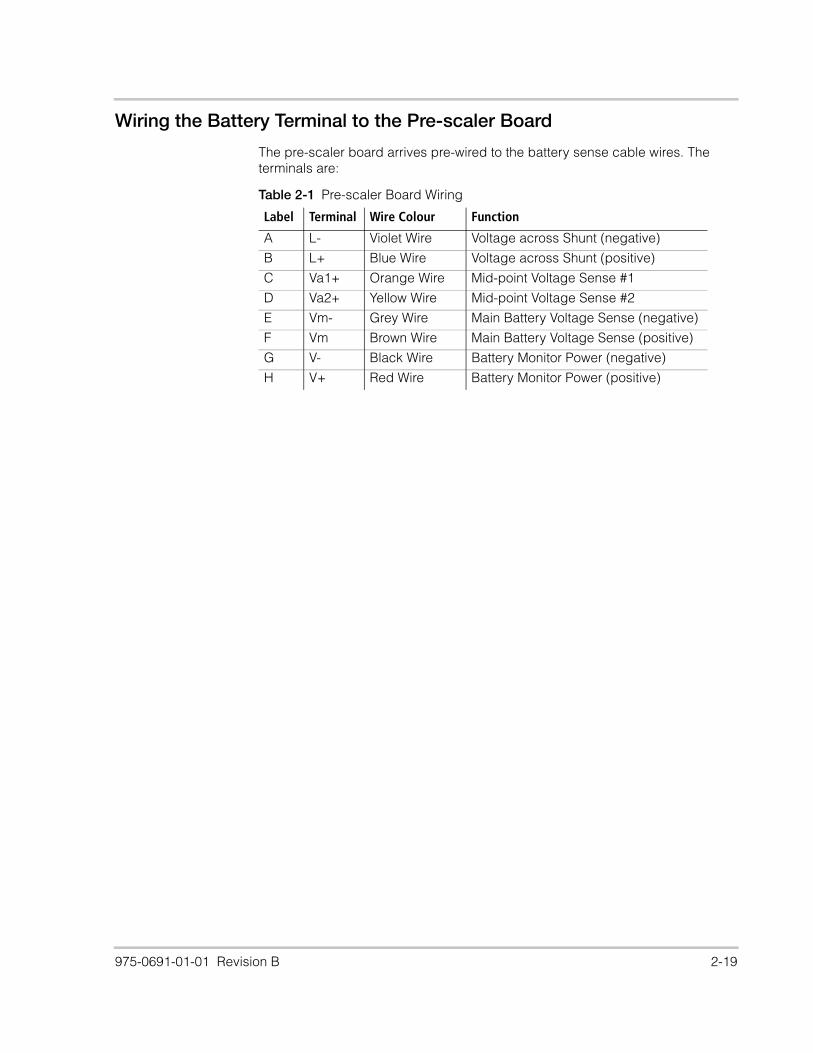
Wiring the Battery Terminal to the Pre-scaler Board
The pre-scaler board arrives pre-wired to the battery sense cable wires. The
terminals are:
Table 2-1 Pre-scaler Board Wiring
Label Terminal Wire Colour Function
A L- Violet Wire Voltage across Shunt (negative)
B L+ Blue Wire Voltage across Shunt (positive)
C Va1+ Orange Wire Mid-point Voltage Sense #1
D Va2+ Yellow Wire Mid-point Voltage Sense #2
E Vm- Grey Wire Main Battery Voltage Sense (negative)
F Vm Brown Wire Main Battery Voltage Sense (positive)
G V- Black Wire Battery Monitor Power (negative)
H V+ Red Wire Battery Monitor Power (positive)

2-20 975-0691-01-01 Revision B
2AT Fuses are pre-wired to V+, Vm, VA1, VA2. L+, and L- are wired together as a
twisted pair, while the remaining wires are individual.
To wire the battery terminal to the Pre-scaler Board:
1. Connect the black (V-) and grey (Vm-) wires to the negative (—) endpoint
battery terminal.
2. Connect the red (V+) and brown (Vm) wires to the positive (+) endpoint
battery terminal.
GH F E D C AB
Pre-Scaler Port
Pre-wired
Connections
Battery Sense Cable
Battery Sense
Cable Wires
Twisted Pair
Figure 2-11 Pre-scaler terminals

975-0691-01-01 Revision B 2-21
Wiring the Shunt to the Pre-Scaler Board
The Pre-scaler board is connected to the shunt via the twisted wire pair which is
wired to the inner screws on the shunt.
Wiring the Pre-Scaler Board to the Battery Monitor
The Pre-scaler board is connected to the Battery Monitor using the orange RJ45
cable provided. Plug the RJ45 cable directly to the port on the Pre-scaler board
then to the Battery Monitor as indicated in Figure 2-9, “Wiring the Battery Monitor”
on page 2–17.
Wiring the RS 485 Modbus Connector to the Battery Monitor
The RS 485 Modbus connector provides three terminals for communication
cable connections to the Battery Monitor. The three-conductor cable can be 16–
24 AWG with 1.5 mm2–0.25 mm2 wires. The cable can be shielded or non-
shielded.
To wire the RS 485 Modbus connector for data communication:
1. Select a two-wire, twisted pair, shielded cable not longer than 164 ft (50 m).
Refer to the local electrical code and application to select the correct cable
insulation and temperature class.
2. Strip 3/8 in. (10 mm) from the end of the wires to be connected and attach
ferrules to the two signal wires.
Connect Blue
wire hereConnect Violet
wire here
Figure 2-12 Wiring the shunt to the Pre-scaler board
DANGER
ELECTRIC SHOCK AND FIRE HAZARD
Turn off all other devices prior to wiring the connectors.
Failure to follow these instructions will result in death or serious injury.

2-22 975-0691-01-01 Revision B
3. Insert the three wires into the connector terminals as shown in Figure 2-13.
4. Secure the wires by tightening the screw on the terminal.
Note: The right terminal is not connected internally but is provided for the
ground connection of the cable.
5. Plug the connector into the rear RS485 port on the Battery Monitor.
USB Mini-B Port
The USB-Mini Port can be used to connect directly to a computer using the
included USB Mini-B to USB 2.0 cable to extract data logs.
Battery Temperature Sensor (BTS)
The BTS port on the back of the Battery Monitor uses a standard RJ11 type
connector to connect the included temperature sensor to the BTS.
Figure 2-13 Wiring the RS 485 modbus connector
GND
D0
D1
3/8 in.
(10 mm)

975-0691-01-01 Revision B 2-23
To connect the BTS cable to the battery:
1. Connect the RJ11 connector to the back of the Battery Monitor as indicated
in Figure 2-9, “Wiring the Battery Monitor” on page 2–17.
2. Connect the BTS connector either by bolting it directly to a battery terminal
along with the other connections or by removing the sticker on the bottom of
the BTS connector and sticking it directly to a surface on the battery. The two
methods are shown in Figure 2-14.
Note: If multiple charge controllers or a complete Power System with Conext
XW+ Inverter/Chargers are networked together using Xanbus, then only one BTS
is required per battery bank. All networked devices share battery temperature
information, and you can connect the BTS to a charge controller or a Conext
XW+ Inverter/Charger. If more than one BTS is used within the system, then the
highest reported temperature from all of the units with an attached BTS will be
used as the battery temperature for the temperature compensation value of the
battery charge algorithm. For a large battery bank, installing the BTS at the
hottest area of the battery bank is recommended.
OR
Figure 2-14 Connecting the BTS cable to the battery

2-24 975-0691-01-01 Revision B

975-0691-01-01 Revision B 3-25
3 Configuration
Chapter 3 describes how to configure settings for the Battery Monitor and perform tasks such as extracting data logs upgrading device firmware. It includes:
• “Initial Startup of the Battery Monitor” on page 26
• “Function Menu” on page 28
• “Statistics Menu” on page 31
• “History Menu” on page 30
• “Reset Menu” on page 31
• “Logging” on page 32
• “Mid-point Sensing” on page 34
• “Synchronization” on page 36
• “Upgrading Firmware” on page 37
• “SCP Menu Map” on page 38

3-26 975-0691-01-01 Revision B
Initial Startup of the Battery Monitor
Note: Use the front panel display for first installation. Do not connect the Xanbus
cables initially because system functions on other Xanbus devices could be
affected as the Battery Monitor initializes.
To turn on the Battery Monitor:
1. Insert the pre-scaler cable into the RJ45 analog-signal port. The Battery
Monitor will power on using battery power.
2. Wait for up to two minutes while the LCD display and Power LED (Figure 3-1)
flash intermittently during the startup and initialization sequence.
3. When the Power LED stops blinking, Hold the OK button for 3 seconds to
enter Setup Mode.
4. When the display reads StAt, press the > key twice. The display should now
switch to read FUnc.
5. Press OK. The display should read F1.0
6. Press OK then use the arrow buttons to adjust Function F1.0 so that it is set
to the float charge voltage level of your battery charger. (i.e. 52.8 V).
7. Press OK, navigate to Function F2.0 then use the arrow buttons to adjust
Function F2.0 to the nominal battery capacity value of your battery system.
(i.e. 200 Ah).
Figure 3-1 Location of front panel power LED indicator

975-0691-01-01 Revision B 3-27
8. The default State-of-charge at startup is 75%. Before synchronizing the
Battery Monitor to a State-of-charge of 100%, charge the batteries
completely and allow the batteries to remain in float state for at least 2 hours.
Refer to “Synchronization” on page 3–36 for synchronization instructions.
Battery Sizing
The amp-hour setting on the Battery Monitor should be set to a value equal or
lower than the actual amp-hour capacity of the system’s battery bank. If a Battery
Monitor is installed on a battery bank that is not brand new, it is likely that the
batteries have aged and lost some Ah capacity. In this case, it is recommended
to set the Ah lower than the rating after conducting a capacity test or consulting
the battery manufacturer. Using a number that is lower than the actual amp-hour
capacity allows the Battery State-of-Charge meter to provide a more
conservative indication for the use of the batteries to avoid excessively
discharging them.
Also note the temperature at which the battery capacity is rated. The amp-hour
capacity of the batteries decreases at temperatures lower than the rated value.
The amp-hour rating is usually printed on the battery’s label. If the system
contains batteries in parallel, then the amp-hour rating of the parallel batteries is
added together (i.e., two 120 amp-hour rated batteries in parallel equals 240
amp-hours). The amp-hour capacity of a bank does not increase for series-wired
batteries and is equal to the lowest rated battery in the series string. If the amp-
hour capacity is not listed on the battery, consult the battery manufacturer or
dealer for assistance.
Changing Settings from the Front Panel
To change settings, press and hold the OK key for three seconds to enter Setup
Mode. Press the > key until the desired setup menu appears.
To enter a menu, press the OK key. The desired settings can then be selected by
pressing the < or > keys.
To alter a specific setting, press OK when the setting is highlighted. The value of
the setting can then be changed by pressing the < or > keys again. When the
desired value is set, press OK to select other settings which need to be changed.
When all settings are correctly configured, press and hold the OK key for three
seconds to save the settings and return to Display Mode.
Note: When no keys are pressed in Setup Mode for 90 seconds, the Battery
Monitor will automatically return to Display Mode without saving any changed
settings. Be sure to press and hold the OK key for three seconds to save all
settings.

3-28 975-0691-01-01 Revision B
Function Menu
In the FUnc (Function) setup menu, the Battery Monitor can be adjusted to fit
your system. Parameters called Functions can be set according to your needs.
This menu can be accessed by following the sequence in “Changing Settings
from the Front Panel” on page 3–27.
The Function menu is divided into three types of settings: System Property
Settings (represented by F1), Main Battery Settings (represented by F2), and
Battery Monitor settings (represented by F3). The following settings are available.
System Property Settings
F1.0 Charger's float voltage. This value must be equal to your battery
charger’s float voltage. which is the last stage of the charging
process. In this stage the battery is considered full.
Default Range Step size
52.8 V 16.0 – 64.0 V 0.1 V
F1.1 Charger's float current. When the charge current is below this percentage of the battery capacity (see Function F 2.0), the battery will be considered as fully charged. Make sure this Function value is always greater than the minimum current at which the charger maintains the battery or stops charging.
Default Range Step size
2.0% 0.5 – 10.0% 0.5%
F1.2 Auto-sync time. This is the time the Auto-sync parameters F1.0 and F1.1 must be met in order to consider the battery as fully charged.
Default Range Step size
240 sec. 5-300 sec. Variable
F1.3 Discharge floor. This is the reference point at which the battery needs to be recharged. When the State-of-charge percentage falls below this value the Charge battery indicator starts flashing while the time remaining readout shows 0:00 and the State-of-charge bar is empty.
Default Range Step size
50% 0.0 – 99.0% 1.0%
F1.4 Battery temperature. With this Function, the average battery temperature can be manually adjusted. This value is used for SOC calculation only. The Battery Monitor will only broadcast temperature on Xanbus if there is a Battery Temperature Sensor connected.
Default Range Step size
+20°C -20 – +50°C 1.0%
F1.5 Time remaining averaging filter. Specifies the time window of the moving averaging filter. There are three settings, where setting 0 gives the fastest Time remaining readout response and setting 2 gives the slowest. The best setting will depend on the type of battery load and your personal preference. The setting represents the effect of reducing battery capacity at higher discharge rates.
Default Range Step size

975-0691-01-01 Revision B 3-29
Main Battery Settings
1 0-2 1
F1.6 Auto-sync sensitivity. Changes sensitivity of the auto-sync function. If it takes too long to activate the synchronization function, lower this value. If it synchronizes too early, increase this value for a later synchronization.
Default Range Step size
5 0-10 1
F2.0 Battery capacity. Your Main battery’s capacity in Amp hours (Ah).
Default Range Step size
200 20-9990 Variable
F2.1 Nominal discharge rate (C-rating). Set in conjunction with battery capacity, F2.0.
Default Range Step size
20h 1-20h 1
F2.2 Nominal temperature. The temperature at which the battery manufacturer rates your battery’s capacity. Set in conjunction with battery capacity, F2.0.
Default Range Step size
+20°C 0 – 40°C 1°C
F2.3 Temperature coefficient. This is the percentage that your battery’s capacity changes with temperature. The unit of this value is percent capacity per degree Celsius. The setting “OFF” disables temperature compensation.
Default Range Step size
0.50% capacity 0.01 – 1.00% capacity 0.01% capacity
F2.4 Peukert’s Exponent. Represents the effect of reducing battery
capacity at higher discharge rates. Properly setting Peukert's
exponent ensures a more accurate display of time remaining and
percent remaining. Note: Consult your battery manufacturer to
understand the value to use based on your model. Refer to
“Peukert’s Exponent for Battery Rating” on page 4–45 for further
details.
Default Range Step size
1.25 1-1.50 0.01
F2.5 Self-discharge rate. Rate at which the battery loses capacity by itself
when not used.
Default Range Step size
OFF 0.1-25% / Month 0.1
F2.6 Charge Efficiency Factor. Ratio between the energy removed from a battery during discharge and the energy used during charging to restore the original capacity. See “How the Charge Efficiency Factor is used” on page 4–44 for more information.
Default Range Step size
AUTOMATIC 50-100%, AUTOMATIC N/A

3-30 975-0691-01-01 Revision B
Battery Monitor Settings
History Menu
The History menu is a read-only menu that shows the Battery Monitor’s Historical
data. Historical data consists of special events that are stored in internal memory.
This menu can be accessed by following the sequence in “Changing Settings
from the Front Panel” on page 3–27.
The following History menu settings are available.
F3.0 Internal firmware version. (Reserved, Read-only value)
F3.1 Shunt Amp Rating. This Function is linked to F3.2 and represents
the Amp rating of your shunt at the given sensing voltage as set in
F3.2. Included with your Battery Monitor is a 500 Amp/50 mV shunt,
meaning that at 500 A flowing through the shunt, a voltage of 50 mV
is generated across the small ‘Kelvin’ screw terminals of the shunt.
This voltage is used by the Battery Monitor to measure the battery
current.
Default Range Step size
500 A 10 – 9000 A Variable
F3.2 Shunt milliVolt Rating. This value represents the milliVolt rating of your
shunt at the rated current. The Battery Monitor supports 50 mV and
60 mV shunts.
Default Range Step size
50mV 50 – 60 mV 1
F3.3 Backlight mode. Represents the duration of backlight activation in
seconds after key-press. The backlight can also be set to be always
“ON” or always “OFF”. Function setting “AU”, activates the backlight
automatically when charge / discharge current exceeds 1 Amp or
when a key is pressed.
Default Range Step size
30 sec OFF / 5 – 300 / ON Variable
F3.4 Temperature scale selection. Enables selection between degrees
Celsius (°C) and degrees Fahrenheit (°F) in the temperature readout.
Default Range Step size
°C °C/°F N/A
F3.5 Setup lock. When set to “ON”, all functions except the Setup lock
function itself are locked and cannot be altered. The Reset menu is
also locked.
Default Range Step size
OFF OFF/ON N/A

975-0691-01-01 Revision B 3-31
Battery History Settings
Statistics Menu
The Statistics menu is a read-only menu that shows the Battery Monitor’s current
statistics for several items. This menu can be accessed by following the
sequence in “Changing Settings from the Front Panel” on page 3–27.
The following Statistics menu items are available:
• St.1 Days running. The number of days the Battery Monitor has been
monitoring the battery. This item resets when a battery reset is executed
(see Reset menu).
• St.2 Days since last synchronized. The number of days since the
Battery Monitor has not been synchronized. This item resets when the
Battery Monitor is synchronized or when a battery reset is executed (see
Reset menu).
• St.3 Charge Efficiency Factor (CEF). The charge efficiency factor used
by the Battery Monitor. Depending on the value set in Function F2.6, this
item displays the automatically calculated CEF or a manually set CEF.
Reset Menu
In the Reset menu, you can reset Battery Monitor settings such as Function and
Statistics. This menu can be accessed by the following sequence:
H1.0 Average discharge in Ah. This number will be recalculated after
each synchronization.
H1.1 Average discharge in %. This number will be recalculated after each
synchronization.
H1.2 Deepest discharge in Ah.
H1.3 Deepest discharge in percent.
H1.4 Total Amp-hours removed. The total number of Amp-hours removed
from the battery. When exceeding 10000 Ah, the units are kAh and
the value displayed must be multiplied by 1000.
H1.5 Total Amp-hours charged. The total number of Amp-hours charged
to the battery. These Amp-hours are not compensated by the Charge
Efficiency Factor (CEF). When exceeding 10000 Ah, the units are
kAh and the value displayed must be multiplied by 1000.
H1.6 Number of charge/discharge cycles.
H1.7 Number of synchronizations. This is the number of times the battery
is fully charged meeting the Auto-sync Functions.
H1.8 Number of full discharges. The number of times the battery has been
fully discharged reaching a state-of-charge of 0.0%.

3-32 975-0691-01-01 Revision B
Hold the OK key for 3 sec until StAt appears on the LCD display, then press the
right arrow button three times. rSt appears on the LCD display. Press the OK
key again, then use the arrow keys to toggle the various items.
The default value for all Reset menu settings is “OFF”. If required, use the < and >
keys to change the value from “OFF” to “ON”. Pressing the OK key again will step
back to the Reset menu. All Reset menu settings which have been set to “ON”
will only be reset once Display Mode is accessed by pressing the OK key for 3
seconds. The following Reset menu items are available:
• rSt.b Reset Battery status. Used to reset the current battery status (Charge
Efficiency Factor, State-of-charge and Battery History). This setting is
intended to be used after installing a new, unused battery which has the
same specifications as the previous battery.
• rSt.c Reset zero-offset current. Use this reset item to remove small current
readings on the display when no current is flowing in or out of the battery.
When performing this reset action, ensure that all DC consumers/chargers
are disconnected or turned off.
• rSt.F Reset Functions. Used to reset all Function values to factory default
values.
Logging
Data logging is an integral function of the Battery Monitor. Data logs record vital
information about the battery over time, such as energy consumption, battery
charging status, and battery state-of-charge (SOC). This information cannot be
displayed in a useful manner without taking data out of data logs. Logging is also
useful for those who wish to gain more detail than provided by the front panel or
who wish to retrieve historical data.
The Battery Monitor keeps data logs of 7 principal functions on an ongoing basis
whenever it is powered on. These functions are:
• Battery Voltage
• Battery Current
• Battery Temperature
• Battery State-of-charge
• Battery Amp-hours Removed
• Mid-point Voltage VA1
• Mid-point Voltage VA2
The record period of the Data Logger function defaults to 300 seconds.

975-0691-01-01 Revision B 3-33
Extracting data logs
To extract data logs, a Mini-USB to USB cable is used to connect from the Battery
Monitor’s Mini-USB port to the computer’s USB port. The data logs are available
in a spreadsheet comma separated values (.csv) format.
To extract data logs:
1. Plug the Mini-USB to USB cable directly from the Battery Monitor’s Mini-USB
port directly to the computer’s USB port.
2. Use “My Computer” or equivalent function to browse for a new drive called
“Logs” as indicated below. The new drive will appear as a device with
removable storage.
3. Double click the “Logs” drive then double click the “DataLog” folder.
4. Double click the folder for the year to be viewed, then double click the folder
for the month to be viewed.
Figure 3-2 Mini-USB to USB cable
Figure 3-3 Example of Battery Monitor logs folder
Figure 3-4 Example of log folders

3-34 975-0691-01-01 Revision B
5. Find the .csv file for the current day and open the file in your preferred
spreadsheet software. The data file is formatted by using a comma to delimit
items. The file can be opened and viewed by most popular spreadsheet
programs such as Microsoft® Excel® or a text editor (i.e. Notepad).
Mid-point Sensing
Mid-Point voltage sensing is a technique used to detect unbalanced battery
strings. The Battery Monitor is capable of sensing three voltage inputs - the main
battery string voltage and two additional voltages on the same battery string.
These two additional voltage measurement inputs can be used to keep track of
voltages across the cells in a string to determine various attributes of battery
health. By having more precise measurements, it is possible to detect issues
such as cell divergence or a dead cell. The voltage inputs are sensed every 5
seconds and updated for monitoring purposes, and they are stored in the log
files at a resolution of every 300 seconds.
Mid-point Sensing Configurations
To use the mid-point sensing feature, wire the battery bank using one of the 2
methods illustrated below, depending on the size of the battery bank. In both
examples, the Va1 and Va2 terminals are connected to the mid-point positive
terminals of the battery cells. Voltages are then measured with reference to the
negative terminal of the battery bank.
Figure 3-5 Example log file (CSV format)

975-0691-01-01 Revision B 3-35
To display the mid-point voltages on the Battery Monitor, press the right arrow
key until the AUX Voltage label is shown. The voltage display on the LCD display
will alternate every 5 seconds between VA1 and VA2 voltages.
Trending Mid-point Voltages in Data Logs
By keeping track of the mid-point Va1 & Va2 between the two battery strings, it is
possible to know if both strings are remaining balanced during charge and
discharge cycles. The most obvious differences can be observed when the
battery is in the range of 70-50% SOC. The effect gets more pronounced as the
cell voltage nears the knee voltage common with lead-acid batteries (i.e.
discharge voltage of the battery after which there is little energy capacity left).
Typical voltage difference of less than 0.5 V to 1 V are acceptable, but when
voltages start to differ beyond 1.5 V for two center taps of a parallel battery
string, it usually means the cells of one string have diverged and need periodic
maintenance (a visual check, water top-up, or equalization, etc.)
Va1Vm Va2
Va1Vm
Va2
2x 2AT fuse
2x 2AT fuse
2AT fuse 2AT fuse
2AT fuse
2AT fuse
Method 1:
Method 2 (parallel battery banks):
Each battery icon represents a 6 V cell.
Figure 3-6 Mid-point sensing configurations

3-36 975-0691-01-01 Revision B
It is not practical to monitor the mid-point voltage throughout the day. Therefore, a
more practical approach is to look at periodic log files stored inside the Battery
Monitor and examine the minimum values recorded for Va1 & Va2. If they differ
beyond 1.5 V, maintenance may be required. Another option is to compare these
minimum voltages to double (two times) the value of Vm. If these are close in
value, it can reasonably be inferred that the batteries are healthy.
Note: The above explanation is provided as a recommendation and not
expected to be an accurate method of determining the state of health for the type
of batteries you own. Consult with the battery manufacturer to determine how the
sensing of mid-point and logging over a period of time can be used for
determining information about battery health and maintenance needs.
Synchronization
In order to keep the Battery Monitor delivering accurate status information about
the battery, it is important to synchronize it regularly. Synchronisation is also
needed before the Battery Monitor can initially be used. During operation, the
Battery Monitor automatically indicates when a synchronisation is required by
displaying the message SYNCHRONIZE.
Performing synchronizations regularly is also important to increase battery life
and keep the battery healthy. If charge cycles are being performed regularly, the
Battery Monitor will most likely not display the SYNCHRONIZE message since the
battery is already being kept in sync with the Battery Monitor.
To manually synchronize the Battery Monitor:
In addition to automatic synchronizations for meeting the Auto-Sync Functions,
the Battery Monitor can be manually synchronized with the battery when the
battery is fully charged. This is done by pressing and holding both < and > keys
simultaneously for three seconds or until the flashing Full message appears on
the display, just like when it is automatically synchronized.
Figure 3-7 Button press for synchronization

975-0691-01-01 Revision B 3-37
A synchronisation step means performing a charge cycle on the battery.
A charge cycle will be considered complete when all discharged energy is
restored in the battery and Auto-sync parameters F1.0, F1.1 and F1.2 are
met (see “System Property Settings” on page 3–28). This typically occurs when
the battery charger switches to float mode. By meeting these conditions, the
battery is considered full, which will be indicated by a flashing Full message on
the display. The State-of-charge readout will also be set to 100% and the Amp-
hour readout reset to 0 Ah. The Full message will disappear when a key is
pressed or automatically when the battery starts discharging again.
Upgrading Firmware
Firmware upgrades for the Battery Monitor and other Xanbus-enabled devices
can be performed whenever required. These upgrades are only possible through
Xanbus communication and can be completed using the Conext Configuration
Tool and included dongle, or with the Conext ComBox.
Be sure to back up all data log files prior to upgrading the firmware. Upgrades for
the Battery Monitor can take five minutes or more depending on various factors,
so be sure to allow enough time for the upgrade to complete. Do not reset any
devices while the upgrade is taking place.
New firmware updates can be found at www.SEsolar.com.
For detailed instructions about upgrading device firmware, refer to the Conext
Configuration Tool Owner’s Guide and the Conext ComBox Owner’s Guide.
Multiple Battery Monitors on the same Xanbus network
When running multiple Battery Monitors on the same Xanbus network, a
maximum of up to 4 Battery Monitors can be connected to various battery sizes
as needed. If multiple Battery Monitors are installed, they should each be
assigned a different Battery Association (e.g. HouseBatt1-HouseBatt4) using the
Conext Configuration Tool, Conext ComBox, or Conext SCP (Multi Menu).

3-38 975-0691-01-01 Revision B
SCP Menu Map
The Conext System Control Panel (SCP) provides remote configuration and
monitoring capability for the Battery Monitor and other Xanbus-enabled devices
in the network. Below is a map of Battery Monitor menu functions.
Note: All data in Figure 3-8 is sample data and may not necessarily correspond
with the data on your system.
Note: If more than one Battery Monitor is present in a system and DC
associations are given default names, the names on other devices could be
[Faster]
Conext BM 00 : Adv
Peukert Expo [1.25V]
Charge Eff [Auto]
Temp Coeff
Sync Sensitivity
[0.5%]
[3]
Time Rem Filter
Multi Unit Config
Restore Defaults
Conext BM 00 : Basic
Capacity [450Ah]
Discharge Rate [20h]
Shunt Amps [500A]
Shunt mV [50mV]
Self Disch [3.0%]
Discharge Floor [50%]
Float Volt [52.8V]
Float Amps [2%]
Temp Unit [Celsius]
Nominal Temp [25øC]
Back Light Timer [30]
Auto Sync Time [240]
Advanced Settings
Basic Settings
Mode [Standby]
Battery Temp 28øC
Time Remaining 03:56 h:m
AH Removed -150Ah
State of Charge 75%
Battery 31.7A57.4V
RS485 Settings
Synchronize Now (control button)
Mid Points 23.8V23.7V
Conext BM 00: RS485 Sett
Address [001]
Baud Rate [119200]
Parity [Even]
Stop Bits [One]
Byte Order [LSB]
Conext BM 00 : Multi
Dev Name
Dev Number
DC Conn
Conext BM 00 : Meters
[BM1]
[00]
[HouseBatt1]
Conext System Control Panel
Battery Monitor Menu Map
Figure 3-8 Conext SCP Battery Monitor Menu Map

975-0691-01-01 Revision B 3-39
duplicated, which could cause system-wide battery bank status readings to be
inaccurate. Be sure to manually configure a unique DC association number for
each Battery Monitor when multiple Battery Monitors are present in a system to
avoid this issue.

3-40 975-0691-01-01 Revision B

975-0691-01-01 Revision B 4-41
4 Monitoring
Chapter 4 describes how the Battery Monitor can monitor system components and explains how displays and functions are calculated. It includes:
• “Indicators and Controls” on page 42
• “Meters” on page 43
• “Theory of Operation” on page 44

4-42 975-0691-01-01 Revision B
Indicators and Controls
The Battery Monitor contains the following controls and indicators:
1. LCD display screen
2. Navigation buttons (<, OK and > keys)
3. Reset button
The LCD display screen displays alphanumeric messages with a three-digit
resolution (0.00). The screen will flash amber when the battery is in an
emergency state requiring attention.
1
2
3
Figure 4-1 Conext Battery Monitor Controls and Indicators

975-0691-01-01 Revision B 4-43
Meters
When not being actively configured, the Battery Monitor is operating in display
mode. By default, it displays the main battery voltage readout. To display one of
the other meters:
• Press the OK button repeatedly until the desired indicator illuminates.
• The LCD display will indicate the values for the currently selected function.
All readout selections can be navigated by using the < and > keys.
The standard readout selection sequence is as follows:
V (battery voltage) > A (charge/discharge current) > Ah (Amount of consumed
Amp-hours) > % (State-of-charge (SOC) > h (Time remaining until a battery
recharge is necessary) > °C (Battery temperature, or temperature setting if BTS
is installed) > V (Mid Point Voltage, if configured).
Available Meters
V (Volts) When this indicator is displayed, the LCD display shows the voltage currently
present at the battery. The range is 0 to 70 Volts. The accuracy is ±0.3%.
A (Amps) When this indicator is displayed, the LCD display shows the currently occurring
charge or load current in amps. The range is from ±0.1 to ±9999 amps with a
refresh rate of one second. The accuracy is ±0.4%.
Ah (Amp-hours) When this indicator is displayed, the LCD display shows the total amp-hours
used since the last time the amp-hour meter was reset. The range is from ±0.00
to ±9990 amp-hours. When the decimal point flashes, it means that more than
10,000 amp-hours have accumulated. In this case, multiply the reading by 1000
(i.e., 111 = 111,000). This meter automatically resets to zero approximately one
minute after the Full LCD stops flashing.
% (State-of-
charge)
When this indicator is displayed, the LCD display shows the battery’s State-of-
charge based upon the amp-hour reading divided by the amp-hour capacity of
the batteries (or battery bank). The values displayed are:
• Lo (when battery is below 27.5%)
• 30 to 90% numerical value (in 5% increments)
• Full (when the battery’s State-of-charge is over 92.5% capacity)
h (Time Remaining) Time remaining until recharge. Limit represented in HH:mm remaining time.
This readout displays “-----” when charging.
°C (Battery Temp) Battery temperature. Indicates the battery temperature if the Battery Temperature
Sensor (BTS) is installed. Otherwise, this will display the temperature as set in
Function F1.4.
V (AUX Volts) Displays the mid-point voltages Va1 and Va2 when mid-point voltage sensing is
used. When selected, this setting will alternate between displaying Va1 and Va2.
See “Mid-point sensing configurations” on page 3–35 for more information.

4-44 975-0691-01-01 Revision B
Theory of Operation
How State-of-charge and Amp-hours are Calculated
The capacity of a battery is rated in amp-hours (Ah). A battery that can deliver a
current of 5 A for a period of 20 hours is rated at 100 Ah (5 × 20 = 100) at a C20
discharge rate. The Battery Monitor continuously measures the current flow in or
out of the battery and calculates the amount of energy removed from or added to
the battery. However, battery age, discharge current, and temperature all
influence the battery’s capacity. When the same 100 Ah battery is discharged
completely in only two hours (a C2 rate) it will provide only 56 Ah. In this case, the
battery’s effective capacity is almost halved. Additionally, when the temperature
of a battery is low, its battery capacity is decreased even more. This is why
simple amp-hour counters or voltmeters cannot provide an accurate state-of-
charge indication.
The Battery Monitor can display both amp-hours removed (not compensated)
and actual state-of-charge. Reading state-of-charge is the best way to read the
battery. This parameter is given as a percentage, where 100.0% represents a
fully charged battery and 0.0% a completely flat battery. It can be thought of in
comparison to a fuel gauge in a car. Discharging lead-acid batteries lower than
50% of SOC is typically not recommended as it may affect battery life.
How the Charge Efficiency Factor is used
Charge Efficiency can be defined as the ratio between the energy removed from
a battery during discharge and the energy replaced into the battery during
charging. Not all energy transferred into the battery during battery charging is
available during subsequent use of the battery. The charge efficiency of a brand
new battery is approximately 90%, which means that 10 Ah must be transferred
into the battery to get 9 Ah actually stored in the battery. This efficiency figure is
called Charge Efficiency Factor (CEF) and decreases as batteries age. The
Battery Monitor automatically calculates the CEF of the battery as the battery is
used. The level at which the CEF is recalculated is variable and is linked to the
discharge floor set in F1.3.
The CEF algorithm starts operating when 10% of the difference between 100%
and the discharge floor is discharged from a fully charged battery. For example,
assume the discharge floor is set to 50%. Then the CEF algorithm starts
operating when 100% - 50% / 10 = 5% is discharged from a fully charged
battery. When the discharge floor is set to 0%, this level is 100% - 0% / 10 = 10%.
How Time Remaining is Computed
The Battery Monitor calculates how long the battery can support the currently
active load. This is referred to as Time Remaining. Time Remaining indicates the
time left until the battery needs to be charged again. If the battery load is
fluctuating heavily, it is best not to rely on this reading since it is a momentarily
calculated readout. This means that it will always reflect the time remaining as

975-0691-01-01 Revision B 4-45
based on the load at the time of readout. Therefore, it should be used as a guide
only. The use of the state-of-charge readout generally gives a more accurate
indication of the overall percentage of battery life remaining.
Time Remaining is still an important readout in certain cases. For example, when
there is a heavy and sustained load, it can be useful to know how much longer
the load can be operated. The time remaining readout will display the total time
available to run the load with the amount of energy available in the battery at the
present time.
Note: The Peukert’s Coefficient is only used to adjust the SOC and Time
Remaining value during a discharge. It is not applied to the Amp-hours Removed
value.
Peukert’s Exponent for Battery Rating
Peukert's Equation describes the effect of different discharge rates on battery
capacity. As the discharge rate increases, the available battery capacity
decreases.
The Battery Monitor uses Peukert's equation for calculating the Time Remaining
function. The amp hours display always shows the actual number of amp hours
consumed. This means that if the battery is rapidly discharged, the time
remaining number may show zero hours remaining before showing the total
number of amp hours of battery capacity consumed.

4-46 975-0691-01-01 Revision B

975-0691-01-01 Revision B 5-47
5 Troubleshooting
Chapter 5 describes troubleshooting for common issues that might be encountered when installing or operating the Battery Monitor. It also describes how the Battery Monitor works with other Xanbus Devices. It includes:
• “Troubleshooting Common Issues” on page 48
• “Interoperability with other Xanbus Devices” on page 49

5-48 975-0691-01-01 Revision B
Troubleshooting Common Issues
To troubleshoot commonly encountered issues, look up the issue in the
troubleshooting table below for possible solutions. If you’re unable to find the
issue, Contact Customer Service for further assistance. Please be prepared to
describe details of your system installation and provide the model and serial
number of the unit. See page 1–i for contact information.
Table 5-1 Troubleshooting Common Issues
Problem Possible cause Solution(s)
The Battery Monitor
doesn't operate (no
display)
Battery not connected or battery
voltage low.
Check Battery Monitor and battery side
connections.
Check battery voltage. Battery might be
flat. Vbatt must be >18 VDC.
Current readout gives
wrong polarity (e.g.
positive current
instead of negative
when discharging)
Current sense leads from the shunt
are reversed.
Confirm proper wiring of leads using the
installation guide.
The Battery Monitor
resets frequently.
Battery might be flat or defective. Check the wiring for corrosion and / or
loose contacts.
No changes can be
made in the Function
setup.
The Battery Monitor might be locked
by the setup lock function.
Check that the setup lock function is
OFF (Function F3.5).
Ask the installer for the password to
unlock the monitor.
“Charge” or
“Synchronize” keeps
flashing on LCD
display.
Battery is not fully charged.
Incorrect parameters.
Charge battery full (synchronize your
battery with the monitor).
Check the Auto-sync parameters in
Functions F1.0, F1.1, and F1.2 for
possible incorrect settings.
State-of-charge and/
or time-to-go readout
not accurate.
Charger or Load connected directly
to Battery negative
Current sense leads from the shunt
are reversed.
Battery Monitor needs to be
synchronized.
Connect all charger and load negative
terminals to the system negative side of
the shunt.
Check all Battery properties Functions
(F2)
Check if Battery Monitor is
synchronized.
Display returns '----'
in temperature
readout
Connection with temperature sensor
is lost.
Check for failed connections and/or
cable damage.

975-0691-01-01 Revision B 5-49
Interoperability with other Xanbus Devices
The Conext Battery Monitor is operable with most of the battery-based XanBus
devices offered by Schneider Electric. Common examples are the Conext XW+
Inverter/Charger, AGS & SCP. The Conext MPPT 60 150, MPPT 80 600 & Conext
SW Inverter/Charger are also capable of operating with the Conext Battery
Monitor with firmware upgrades.
Battery Status
When the Battery Monitor is available on the XanBus network, the voltage, current
& SOC% information which it broadcasts are displayed, reported and used at the
system level. Each device individually reports a different DC voltage as
measured at its input terminals.
Time
The Battery Monitor has a real-time clock with a battery backup. This clock is set
to the PST time zone (UTC-08:00) when shipped. When the Battery Monitor is
plugged into a XanBus network with a ComBox or System Control Panel, it will
synchronize the time in the following order of hierarchy:
1. ComBox
Battery voltage
readout is inaccurate
Voltage drop within the circuit. Check connections and verify that the
cable lengths are within the limits. See
“Planning and Choosing a Location” on
page 9 for correct cable lengths.
Battery State-of-
Charge displays
100% when voltage is
low.
Amp-hour setting is too low. Reconfigure the Amp-hour setting using
Function F1.1 (Charger float current) to
an appropriate value. See “System
Property Settings” on page 3–28 for
further information.
“Full” continues to
display on the LCD
screen even though
the current flow is
negative (battery
discharging)
continuously for one
minute.
Charger float voltage may be set too
low.
Reconfigure the charged voltage using
Function F1.0 (Charger float voltage) to
an appropriate value. See “System
Property Settings” on page 3–28 for
further information.
Battery Monitor SOC
jumpst to 100%
prematurely.
Fluctuations in charging current
around boundary limits for
Synchronization conditions.
Change the F1.0 (Charger float voltage)
to the Absorption voltage, ensuring
100% synchronization only happens
after all Ah are put back into batteries.
Problem Possible cause Solution(s)

5-50 975-0691-01-01 Revision B
2. SCP (if ComBox is not present)
Temperature
The Battery Monitor can be connected to a Battery Temperature Sensor (BTS) to
provide status information on the temperature (in °C) at which the connected
battery is operating. This information is used in SOC% and reserve capacity
calculation. The Battery Monitor broadcasts this temperature information on the
XanBus network which can then be used by other XanBus devices that are
charging batteries to compensate voltage based on the highest temperature
reported by devices on the same battery bank.
Operation with System Control Panel
The Conext SCP features configuration and status monitoring for the Battery
Monitor. See “SCP Menu Map” on page 3–38 for the menu maps and available
fields accessible through SCP.
Operation with Automatic Generator Start
The Battery Monitor allows for one additional trigger to start and stop a generator
based on SOC%. When the Conext Battery Monitor is present on the XanBus
network with other battery based devices, the Conext AGS uses Battery Voltage
status information from the Battery Monitor.
Operation with Conext XW+ Inverter/Charger
The Battery Monitor broadcasts State-of-charge information using XanBus. This
allows The Conext XW+ Inverter/Charger to use the Battery Monitor’s date
instead of its own internal State-of-charge calculation. This technique helps to
achieve a more accurate and consistent State-of-charge display on all XW units
connected to same battery bank. In the future, advanced charging algorithms for
lead-acid batteries will also be implemented using the Battery Monitor.
Operation with Conext ComBox
The Battery Monitor behaves like a regular XanBus device on the ComBox and
provides functionality similar to the Conext SCP through the ComBox. In addition,
the ComBox uses the battery status information broadcast by the Battery Monitor
to display a daily summary of the Voltage, Amps, SOC, and Temperature trends.
The following table provides the firmware version necessary for device operation
with the Battery Monitor:
Table 5-2 Device Compatibility with Conext Battery Monitor
Device Name Firmware Version
Conext XW+ Inverter/Charger 2.0.0 and higher
Conext AGS 2.07 and higher
Conext SCP 2.00 and higher

975-0691-01-01 Revision B 5-51
Conext ComBox 1.04 and higher
Conext ComBox App 1.0.20 and higher
Table 5-2 Device Compatibility with Conext Battery Monitor
Device Name Firmware Version

5-52 975-0691-01-01 Revision B

975-0691-01-01 Revision B A-53
A Specifications
Appendix A contains the electrical, mechanical, and physical specifications for the Conext Battery Monitor. It also contains regulatory standards, supplementary data and information about compatible devices.
Note: All specifications are subject to change without notice.

A-54 975-0691-01-01 Revision B
Electrical Specifications
Resolution
Accuracy
Connections
Features
Supply Voltage 18 to 66 VDC
Supply Current
(backlight Off, logging-
disabled)
80 mA @ VIN=48 VDC, 150 mA @ Vin=24 VDC
Input Voltage Range
(main battery)
0 to 70 VDC
Input Current Range -9999 to +9999A
Battery Capacity
Range
20 to 10,000 Ah
Operating Temperature
Range
-20 to +50°C (-4 to 122°F)
Power Consumption <4 W
Voltage 0 to 70 V (+0.01 V)
Current 0 to 200 A / 200 to 9999 A (+0.1 A / +1 A)
Amp-hours 0 to 200 AH / 200 to 9990 AH (+0.1 Ah / +1 Ah)
State-of-Charge 0 to 100% (+0.1%)
Time Remaining 0 to 24hrs / 24 to 240hrs (+1 min / +1 hr)
Temperature -20 to +50°C / -4 to 122°F (+0.1°C)
Voltage Measurement ±0.3%
Current Measurement ±0.4%
Battery Voltage, Shunt/
Temp Sensor
RJ45 / RJ11 (cables included)
USB mini-B - Device Connector: USB mini-B, Protocols: MSD (data
extraction)
Network Protocol: Xanbus / Connectors: RJ45
USB 2.0 Protocol: MSD (data extraction)
Connector: USB mini-B

975-0691-01-01 Revision B A-55
ModBus Isolated RS-485, half-duplex, 2-wire serial
Data Logging 10 data points every 10 minutes for 10 years
Display Backlit LCD
User interface 3 front panel menu buttons, 1 power button
Battery string-
imbalance detection
Two-point sensing
Temperature Sensor
(included)
762 cm (300 in.)
Warranty 2-5 years depending on country

A-56 975-0691-01-01 Revision B
Mechanical Specifications
Battery Interface Kit with Shunt (Included)
Dimensions (H x W x D) 8.5 x 8.5 x 9.0 cm (3.3 x 3.3 x 3.5 in.)
Product/Shipping Weight 0.2 kg (0.4 lb) / 1.95 kg (4.3 lb)
Mounting System Panel mount, Wall mount, DIN rail: 35mm
IP Rating/Location IP 20, NEMA 1, Indoor Only
Storage Temperature Range -30 to +70°C (-22 to 158°F)
Part number 865-1080-01
Connection to Battery 300 cm cable with ring terminals
Connection to Battery Monitor 500 cm CAT5 cable RJ45
Shunt 500 A / 50 mV
Shunt dimensions 8.7 x 4.5 x 3.5 cm (3.4 x 1.6 x 1.3 in.)
Shunt weight 0.15 kg (0.3 lb)

975-0691-01-01 Revision B A-57
Regulatory Standards
Schneider Electric Products compatible with the Battery Monitor
• Conext XW+ 5548 NA (865-5548-01)
• Conext XW+ 6848 NA (865-6848-01)
• Conext XW+ 7048 E (865-7048-61)
• Conext XW+ 8548 E (865-8548-61)
• Conext SW 2524 230 (865-2524-61)
• Conext SW 4024 230 (865-3524-61)
• Conext SW 2524 120 (865-2524)
• Conext SW 4024 120 (865-3524)
• Conext MPPT 60 150 (865-1030-1)
• Conext MPPT 80 600 (865-1032)
• Conext SCP (865-1050)
• Conext AGS (865-1060-01)
• Conext ComBox (865-1058)
Markings CE
EMC Directive 2004/108/EC, IEC/EN61000-6-3, IEC/EN61000-6-
1, FCC Part 15 Class B, Industry Canada ICES-003 Class B

A-58 975-0691-01-01 Revision B

975-0691-01-01 Revision B B-59
B Modbus Maps
Appendix B contains the Modbus register address maps.
Note: All data is subject to change without notice.

Modbus Maps
B-60 975-0691-01-01 Revision B
Overview
This appendix describes the structure of the Modbus register address map,
which is used to configure and control the Conext Battery Monitor. The
information in this document is intended for use only by qualified persons who
have a detailed technical understanding of the Modbus protocol.
The Modbus map is divided into rows of Modbus registers. Each row indicates
the Modbus register address, its SYSVAR names, Modbus address, Access
types and data types. External Modbus Master devices can read and write the
Modbus registers to configure, control, or monitor the device remotely.
Supported Modbus Data Types
Table 1 lists the supported data types.
WARNING
UNINTENDED OPERATION
The use of this product with Modbus communications requires expertise in the
design, operation, and programming of the device. Only qualified persons
should program, install, alter, and commission this product.
When writing values to the device, ensure nobody else is working with the
device.
Failure to follow these instructions can result in death or serious injury,
and/or equipment damage.
Table 1 Modbus Data Types
Data Type Description
uint16 unsigned 16-bit integer [0,65535]
uint32 unsigned 32-bit integer [0,4294967295]
sint32 signed 32-bit integer [-2147483648,2147483647]
str<nn> packed 8-bit character string, where <nn> is the length of
characters in the string. Two characters are packed into each
Modbus register.
Example:
str20 = 20-character string (packed into 10 Modbus registers)
str16 = 16-character string (packed into 8 Modbus registers)

Converting Data to Units of Measurement
975-0691-01-01 Revision B B-61
Converting Data to Units of Measurement
Data from a Modbus register is converted to units of measurement using the
following algorithm:
result = [(data @ Modbus Register) * scale] + offset
Example: Read the Nominal Temperature
The following example shows a conversion of the nominal temperature located at
Modbus Address 0x0400.
Modbus Address = 0x0400
Scale = 0.01
Offset = -273.0
Data type = uint16 (one Modbus register)
units: degree C
Reading one Modbus Register from address 0x0400 yields 0x7440
Apply the offset and scale as follows:
result = (0x7440 * 0.01) + (-273.0)
= (29760 * 0.01) + (-273.0)
= 297.60 + (-273.0)
= 24.60
The conversion yields a nominal temperature of 24.60 degrees Celsius.
Writing Modbus Registers
Modbus does not provide an error response when data written to a Modbus
Register is out of range or invalid. To confirm that a Modbus Register is correctly
written, you should read it back and compare it with the expected value.
Battery Monitor Device Modbus MapModbus
Address Name Type Access Units Scale Offset Notes
0x0100 Device Name str16 r
0x010A FGA Number str20 r
0x0114 Firmware Version str15 r
0x011E Hardware Serial Number str20 r
0x0200 Operating Mode uint16 r Enum1
0x0201 Battery Voltage sint32 r V 0.001 0
0x0203 Battery Current sint32 r A 0.001 0
0x0205 Battery Temperature uint16 r degree C 0.01 0

Modbus Maps
B-62 975-0691-01-01 Revision B
0x0206 Battery State of Charge uint16 r % 1 0
0x0207 Battery Midpoint VA1 sint32 r V 0.001 0
0x0209 Battery Midpoint VA2 sint32 r V 0.001 0
0x020B Battery AH remaining uint16 r Ah 1 0
0x020C Battery AH removed uint16 r Ah 1 0
0x020D Temperature Sensor uint16 r 0= Not Present
1=Present
0x020E Time to Discharge uint16 r Min 1 0
0x0300 Average Discharge uint16 r Min
0x0301 Average Discharge % uint16 r %
0x0302 Deepest Discharge uint16 Ah
0x0303 Deepest Discharge % uint16 %
0x0304 AH Removed uint32 Ah
0x0306 AH Returned uint32 Ah
0x0308 Number of Charge Cycles uint16
0x0309 Number of Synchronizations uint16
0x030A Number of Discharges uint16
0x0400 Nominal Temperature uint16 rw degree C 0.01 -273
0x0401 Temperature Unit uint16 rw 0=Fahrenheit
1=Celsius
0x0402 Nominal Discharge uint16 rw Hours 1 0
0x0403 Self Discharge uint16 rw % 0.1 0
0x0404 Shunt Amp rating uint16 rw A Enum2
0x0405 Shunt Volt rating uint16 rw mV 0 = 50mV
1 = 60mV
0x0406 Backlight Duration uint16 rw Sec Enum3
0x0407 Float Voltage uint16 rw V 0.001 0
0x0408 Float Current uint16 rw % 0.1 0
0x0409 Discharge Floor uint16 rw % 1 0
0x040A Auto Synchronization Time uint16 rw Sec Enum4
0x040B Battery AH Capacity uint16 rw Ah 1 0
0x0500 Battery Association uint16 r Enum5
0x0501 Battery Temp Coeff uint16 rw %Ah/
degree C
0.01 0
0x0502 Lock Settings uint16 rw 0=Off 1=On
Modbus
Address Name Type Access Units Scale Offset Notes

Battery Monitor Device Modbus Map
975-0691-01-01 Revision B B-63
0x0503 Time Remaining Filter uint16 rw 00 = Fastest
01 = Faster
02 = Fast
0x0504 Auto Synchronization Sens uint16 rw 1 0
0x0505 Battery Peukert Expo uint16 rw 0.002 1
0x0506 Charge Eff Calc Mode uint16 rw 0=Manual 1=Auto
0x0507 Charge Efficiency Factor uint16 rw % 1 0
0x0508 Default Battery Temperature sint16 rw degree C 1 0
0x0600 Modbus Address uint16 rw 1 0
0x0601 Modbus BaudRate sint32 rw bps 1 0 Enum6
0x0603 Modbus Parity str2 rw 00 = None
01 = Odd
02 = Even
0x0604 Modbus Stop Bits uint16 rw 1 0 1=1 2=2
0x0605 Modbus Byte Order uint16 rw 1 0 0=LSB 1=MSB
Modbus
Address Name Type Access Units Scale Offset Notes

Modbus Maps
B-64 975-0691-01-01 Revision B

Printed in China
Schneider Electric
www.SESolar.com
For other country details please contact your local Schneider Electric Sales Representative or visit the Schneider Electric website at:
http://www.sesolar.com/where-to-buy/
975-0691-01-01 Revision B


