Owner's Manual 15.5 HP, 42" Mower Electric Start 6 Speed Transaxle Model No. 917.271554 This product has a low emission engine which operates differently from previously built engines. Before you start the engine, read and understand this Owner's Manual. CAUTION: Read and follow all Safety Rules and Instructions before operating this equipment. For answers to your questions about this product, Call: 1-800-659-5917 Sears Craftsman Help Line 5 am -5 pro, Mon- Sat Sears, Roebuck and Co., Hoffman Estates , II 60179 U.S.A. Visit our Craftsman website:www.sears.com/craftsman
Transcript
Owner's Manual
15.5 HP, 42" MowerElectric Start
6 Speed Transaxle
Model No.917.271554
This product has a low emission engine which operatesdifferently from previously built engines. Before you start theengine, read and understand this Owner's Manual.
CAUTION:
Read and follow all SafetyRules and Instructions before
operating this equipment.
For answers to your questions
about this product, Call:
1-800-659-5917Sears Craftsman Help Line5 am - 5 pro, Mon- Sat
Sears, Roebuck and Co., Hoffman Estates , II 60179 U.S.A.Visit our Craftsman website:www.sears.com/craftsman
Maintenance ....................................... 17Service and Adjustments .................... 21Storage ............................................... 27Troubleshooting ................................. 28Repair Parts ........................................ 32Sears Service ...................... Back Cover
LIMITED WARRANTY ON CRAFTSMAN RIDING EQUIPMENTFor two (2) years from the date of purchase, if this Craftsman Riding Equipment ismaintained, lubricated and tuned up according to the instructions in the owner'smanual, Sears will repair or replace free of charge any parts that are found to bedefective in material or workmanship according to the guidelines of coverage listedbelow. Sears will also provide free labor for these applicable warranted parts for thetwo full years. During the first 30 days of purchase, there will be no charges to servicethe product at your home for issues covered by this warranty. (See exclusions below).For your convenience, IN HOME warranty service will still be available after the first 30days of purchase, but a trip charge will apply. This charge will be waived if the Crafts-man product is dropped off at an authorized Sears location. For the nearest authorizedSears location, please call 1-800-4-MY-HOME®. This warranty applies only while thisproduct is within the United States.
This Warranty does not cover:• Expendable items which become worn during normal use, including but not limited
to blades, spark plugs, air cleaners, belts, and oil filters.• Standard Maintenance Servicing, oil changes, or tune-ups• Tire replacement or repair caused by punctures from outside objects, such as nails,
thorns, stumps, or glass.• Repairs necessary because of operator abuse, including but not limited to, damage
caused by towing objects beyond the capability of the riding equipment, impactingobjects that bend the frame or crankshaft, or over-speeding the engine.
• Repairs necessary because of operator negligence, including but not limited to,electrical and mechanical damage caused by improper storage, failure to use theproper grade and amount of engine oil, failure to keep the deck clear of flammabledebris, or failure to maintain the equipment according to the instructions contained inthe owner's manual.
• Engine (fuel system) cleaning or repairs caused by fuel determined to be contami-nated or oxidized (stale). In general, fuel should be used within 30 days of itspurchase date.
• Normal deterioration and wear of the exterior finishes, or product label replacement.• Riding equipment used for commercial or rental purposes.
LIMITED WARRANTY ON BATTERY
For ninety (90) days from date of purchase, if any battery included with this ridingequipment proves defective in material or workmanship and our testing determines thebattery will not hold a charge, Sears will replace the battery at no charge. During thefirst 30 days of purchase, there will be no charges to replace the battery at your HOME.After the first 30 days, for your convenience, IN-HOME warranty service will still beavailable but a trip charge will apply. This charge will be waived if the Craftsmanproduct is dropped of at an authorized Sears location. For the nearest authorizedSears location, please call 1-800-4-MY-HOME®.
This battery warranty applies only while this product is within the United States.
This warranty gives you specific legal rights, and you may also have other rights, whichvary, from state to state.
Sears, Roebuck and Co.,Dept.817WA, Hoffman Estates, IL 60179
2
IMPORTANT: This cutting machine is capable of amputating hands and feet andthrowing objects. Failure to observe the following safety instructions could result inserious injury or death.
,_li, Look for this symbol to point outimportant safety precautions. It meansCAUTION!!! BECOMEALERT!!! YOURSAFETY IS INVOLVED.
,_ CAUTION: In order to preventaccidental starting when setting up,transporting, adjusting or making repairs,always disconnect spark plug wire andplace wire where it cannot contact sparkplug.
CAUTION: Do not coast down a hill
in neutral, you may lose control of thetractor.
CAUTION: Tow only the attachments
that are recommended by and complywith specifications of the manufacturer ofyour tractor. Use common sense whentowing. Operate only at the lowestpossible speed when on a slope. Tooheavy of a load, while on a slope, isdangerous. -13res can lose traction withthe ground and cause you to lose controlof your tractor.
WARNING: Engine exhaust, some ofits constituents, and certain vehiclecomponents contain or emit chemicalsknown to the State of California to causecancer and birth defects or other repro-ductive harm..
WARNING: Battery posts, terminalsand related accessories contain leadand lead compounds, chemicals knownto the State of California to cause cancerand birth defects or other reproductiveharm. Wash hands after handling.
I. GENERAL OPERATION
• Read, understand, and follow allinstructions in the manual and on themachine before starting.
• Only allow responsible adults, who arefamiliar with the instructions, to operatethe machine.
• Clear the area of objects such as rocks,toys, wire, etc., which could be pickedup and thrown by the blade.
• Be sure the area is clear of other peoplebefore mowing. Stop machine if anyoneenters the area.
• Never carry passengers.
• Do not mow in reverse unless absolutelynecessary. Always look down andbehind before and while backing.
• Be aware of the mower dischargedirection and do not point it at anyone.Do not operate the mower without eitherthe entire grass catcher or the guard inplace.
• Slow down before turning.• Never leave a running machine
unattended. Always turn off blades, setparking brake, stop engine, and removekeys before dismounting.
• Turn off blades when not mowing.• Stop engine before removing grass
catcher or unclogging chute.• Mow only in daylight or good artificial
light.• Do not operate the machine while under
the influence of alcohol or drugs.• Watch for traffic when operating near or
crossing roadways.• Use extra care when loading or unload-
ing the machine into a trailer or truck.• Data indicates that operators, age 60
years and above, are involved in a largepercentage of riding mower-relatedinjuries. These operators shouldevaluate their ability to operate the ridingmower safely enough to protect them-selves and others from serious injury.
• Keep machine free of grass, leaves orother debris build-up which can touchhot exhaust / engine parts and bum. Donot allow the mower deck to plow leavesor other debris which can cause build-up to occur. Clean any oil or fuelspillage before operating or storing themachine. Allow machine to cool beforestorage.
II. SLOPE OPERATION
Slopes are a major factor related to loss-of-control and tipover accidents, which can re-sult in severe injury or death. All slopesrequire extra caution. If you cannot back upthe slope or if you feel uneasy on it, do notmow it.
3
DO:
• Mow up and down slopes, not across.• Remove obstacles such as rocks, tree
limbs, etc.• Watch for holes, ruts, or bumps. Uneven
terrain could overturn the machine. Tallgrass can hide obstacles.
• Use slow speed. Choose a low gear sothat you will not have to stop or shiftwhile on the slope.
• Follow the manufacturer's recommenda-
tions for wheel weights or counter-weights to improve stability.
• Use extra care with grass catchers orother attachments. These can changethe stability of the machine.
• Keep all movement on the elopes slowand gradual Do not make suddenchanges in speed or direction.
• Avoid starting or stopping on a slope. Iftires lose traction, disengage the bladesand proceed slowly straight down theslope.
DO NOT:
• Do not turn on slopes unless necessary,and then, turn slowly and graduallydownhill, if possible.
• Do not mow near drop-offs, ditches, orembankments. The mower couldsuddenly turn over if a wheel is over theedge of a cliff or ditch, or if an edgecaves in.
• Do not mow on wet grass. Reducedtraction could cause sliding.
• Do not try to stabilize the machine byputting your foot on the ground.
• Do not use grass catcher on steepslopes.
Ill. CHILDREN
Tragic accidents can occur if the operatoris not alert to the presence of children.Children are often attracted to themachine and the mowing activity. Neverassume that children will remain whereyou last saw them.• Keep children out of the mowing area
and under the watchful care of anotherresponsible adult.
• Be alert and turn machine off if childrenenter the area.
• Before and when backing, look behindand down for small children.
• Never carry children. They may fall offand be seriously injured or interferewith safe machine operation.
• Never allow children to operate themachine.
• Use extra care when approaching blindcorners, shrubs, trees, or other objectsthat may obscure vision.
IV. SERVICE
• Use extra care in handling gasolineand other fuels. They are flammableand vapors are explosive.-Use only an approved container.- Never remove gas cap or add fuelwith the engine running. Allowengine to cool before refueling. Donot smoke.
-Never refuel the machine indoors.- Never store the machine or fuelcontainer inside where there is anopen flame, such as a water heater.
• Never run a machine inside a closedarea.
• Keep nuts and bolts, especially bladeattachment bolts, tight and keepequipment in good condition.
• Never tamper with safety devices.Check their proper operation regularly.
• Keep machine free of grass, leaves, orother debris build-up. Clean oil or fuelspillage. Allow machine to cool beforestoring.
• Stop and inspect the equipment if youstrike an object. Repair, if necessary,before restarting.
• Never make adjustments or repairswith the engine running.
• Grass catcher components are subjectto wear, damage, and deterioration,which could expose moving parts orallow objects to be thrown. Frequentlycheck components and replace withmanufacturer's recommended parts,when necessary.
• Mower blades are sharp and can cut.Wrap the blade(s) or wear gloves, anduse extra caution when servicing them.
• Check brake operation frequently.Adjust and service as required.
4
• Be sure the area is clear of otherpeople before mowing. Stop machine ifanyone enters the area.
• Never carry passengers or childreneven with the blades off.
• Do not mow in reverse unless abso-lutely necessary. Always look downand behind before and while backing.
• Never carry children. They may fall offand be seriously injured or interferewith safe machine operation.
• Keep children out o! the mowing areaand under the watchful care of anotherresponsible adult.
• Be alert and turn machine off il childrenenter the area.
• Before and when backing, look behindand down for small children.
• Mow up and down slopes (15 ° Max),not across.
• Remove obstacles such as rocks, treelimbs, etc.
• Watch for holes, ruts, or bumps.Uneven terrain could overturn themachine. Tall grass can hide obstacles.
• Use slow speed. Choose a low gear sothat you will not have to stop or shiftwhile on the slope.
• Avoid starting or stopping on a slope. Iftires lose traction, disengage theblades and proceed slowly straightdown the slope.
• If machine stops while going uphill,disengage blades, shift into reverseand back down slowly.
• Do not turn on slopes unless neces-sary, and then, turn slowly and gradu-ally downhill, if possible.
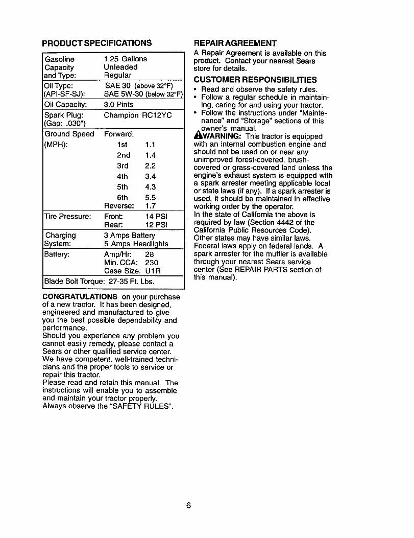
CONGRATULATIONS on your purchaseof a new tractor. It has been designed,engineered and manufactured to giveyou the best possible dependability andperformance.Should you experience any problem youcannot easily remedy, please contact aSears or other qualified service center.We have competent, well-trained techni-cians and the proper tools to service orrepair this tractor.Please read and retain this manual. Theinstructions will enable you to assembleand maintain your tractor properly.Always observe the "SAFETY RULES".
REPAIR AGREEMENT
A Repair Agreement is available on thisproduct. Contact your nearest Searsstore for details.
CUSTOMER RESPONSIBILITIES
• Read and observe the safety rules.• Follow a regular schedule in maintain-
ing, caring for and using your tractor.• Follow the instructions under "Mainte-
nance" and "Storage" sections of this_owner's manual.
WARNING: This tractor is equippedwith an internal combustion engine andshould not be used on or near anyunimproved forest-covered, brush-covered or grass-covered land unless theengine's exhaust system is equipped witha spark arrester meeting applicable localor state laws (if any). If a spark arrester isused, it should be maintained in effectiveworking order by the operator.In the state of California the above is
required by law (Section 4442 of theCalifornia Public Resources Code).Other states may have similar laws.Federal laws apply on federal lands. Aspark arrester for the muffler is availablethrough your nearest Sears servicecenter (See REPAIR PARTS section ofthis manual).
6
Steering Wheel
_gSleeve
(lw)aL_rge Flat
@_ (1) Locknut 1/4-28
(1) Hex Bolt 1/4-28 x 1-1/4
SteeringWheel
Insert
SteeringWheelAdapter
SteeringExtensionShaft
(1) Locknut 1/2-20
Seat
(1) Washer17/32 x 1-3/16 x 12 Gauge
(1) Knob
Keys
(2) Keys
Video Cassette Slope Sheet
7
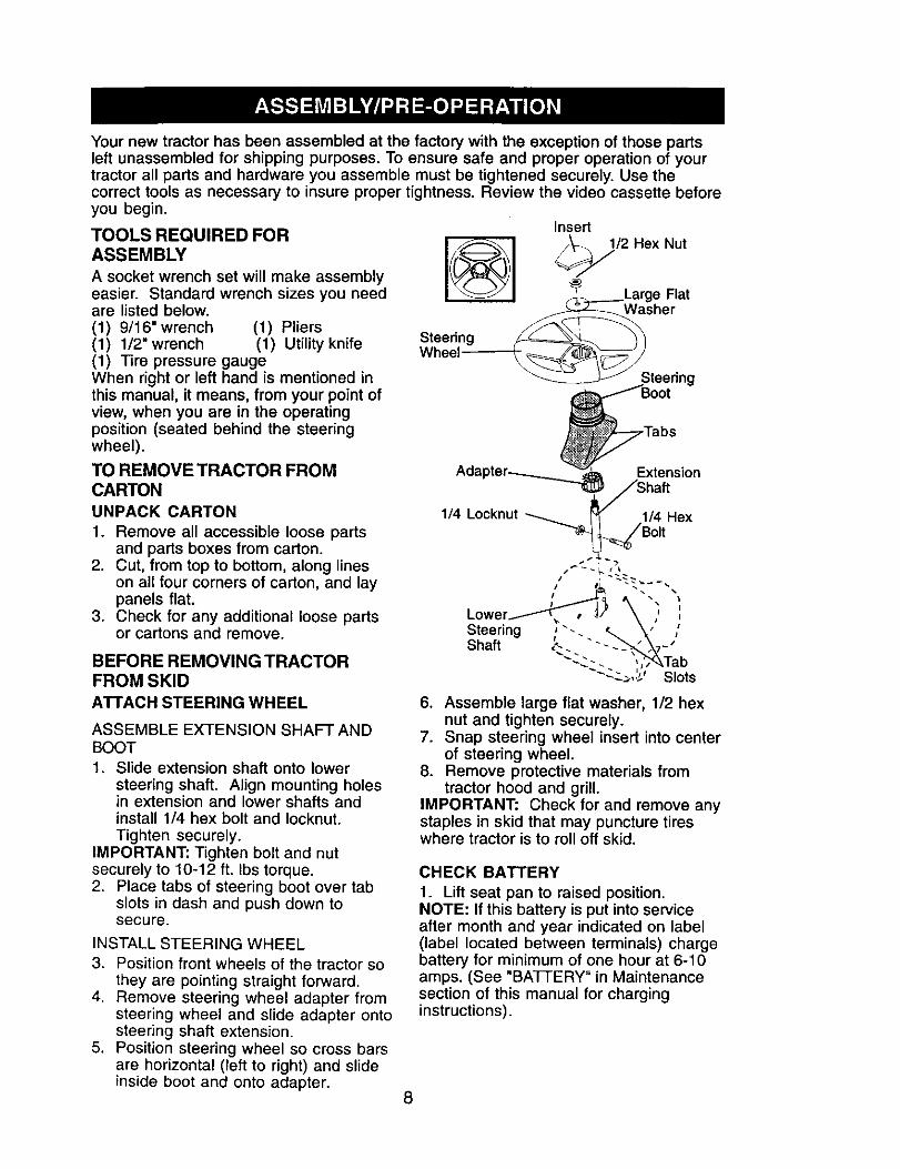
Your new tractor has been assembled at the factory with the exception of those partsleft unassembled for shipping purposes. To ensure safe and proper operation of yourtractor all parts and hardware you assemble must be tightened securely. Use thecorrect tools as necessary to insure proper tightness. Review the video cassette beforeyou begin.
TOOLS REQUIRED FORASSEMBLY
A socket wrench set will make assemblyeasier. Standard wrench sizes you needare listed below.(1) 9/16"wrench (1) Pliers(1) 1/2" wrench (1) Utility knife(1) Fire pressure gaugeWhen right or left hand is mentioned inthis manual, it means, from your point ofview, when you are in the operatingposition (seated behind the steeringwheel).
TO REMOVE TRACTOR FROMCARTONUNPACK CARTON
1. Remove all accessible loose partsand parts boxes from carton.
2. Cut, from top to bottom, along lineson all four corners of carton, and laypanels flat.
3. Check for any additional loose partsor cartons and remove.
5. Position steering wheel so cross barsare horizontal (left to right) and slideinside boot and onto adapter.
6. Assemble large flat washer, 1/2 hexnut and tighten securely.
7. Snap steering wheel insert into centerof steering wheel.
8. Remove protective materials fromtractor hood and grill.
IMPORTANT: Check for and remove anystaples in skid that may puncture tireswhere tractor is to roll off skid.
CHECK BATTERY
1. Lift seat pan to raised position.NOTE: If this bakery is put into serviceafter month and year indicated on label(label located between terminals) chargebattery for minimum of one hour at 6-10amps. (See "BATTERY" in Maintenancesection of this manual for charginginstructions).
8
Seat
Label
erminal
INSTALL SEAT
Adjust seat before tightening adjustmentknob.1. Remove adjustment knob and flat
washer securing seat to cardboardpacking and set aside for assembly ofseat to tractor.
2. Pivot seat upward and remove fromthe cardboard packing. Remove thecardboard packing and discard.
3. Place seat on seat pan so head ofshoulder bolt is positioned over largeslotted hole in pan.
4. Push down on seat to engageshoulder bolt in slot and pull seattowards rear of tractor.
5. Pivot seat and pan forward andassemble adjustment knob and flatwasher loosely. Do not tighten.
6. Lower seat into operating position andsit in seat.
7. Slide seat until a comfortable positionis reached which allows you to pressclutch/brake pedal all the way down.
8. Get off seat without moving itsadjusted position.
NOTE: You may now roll or drive yourtractor off the skid. Follow the appropriateinstruction below to remove the tractorfrom the skid.
TO ROLLTRACTOR OFFSKID (SeeOperation section for location andfunction of controls)1. Press lift lever plunger and raise
attachment lift lever to its highestposition.
2. Release parking brake by depressingclutch/brake pedal.
3. Place gearshift lever in neutral (N)position.
4. Roll tractor forward off skid.5. Remove banding holding deflector
shield up against tractor.
TO DRIVE TRACTOR OFF SKID (SeeOperation section for location andfunction of controls)_,_WARNING: Before starting, read,understand and follow all instructions inthe Operation section of this manual. Besure tractor is in a well-ventilated area. Besure the area in front of tractor is clear ofother people and objects.1. Be sure all the above assembly steps
have been completed.2. Check engine oil level and fill fuel tank
with gasoline.3. Sit on seat in operating position,
depress clutch/brake pedal and setthe parking brake.
4. Place gear shift lever in neutral (N)position.
5. Press lift lever plunger and raiseattachment lift lever to its highestposition.
6. Start the engine. After engine hasstarted, move throttle control to idleposition.
7. Depress clutch/brake pedal into full"BRAKE" position and hold. Movegearshift lever to 1st gear.
8. Slowly release clutch/brake pedal andslowly drive tractor off skid.
9. Apply brake to stop tractor, set parkingbrake and place gearshift lever inneutral position.
10.Turn ignition key to "STOP" position.Continue with the instructions that fotlow.
9
CHECK TIRE PRESSURE
The tires on your tractor were overinflatedat the factory for shipping purposes.Correct tire pressure is important for bestcutting performance.• Reduce tire pressure to PSI shown in
"PRODUCT SPECIFICATIONS" sectionof this manual.
CHECK DECK LEVELNESS
For best cutting results, mower housingshould be properly leveled. See "TOLEVEL MOWER HOUSING" in the
Service and Adjustments section of thismanual.
CHECK FOR PROPER POSITION OFALL BELTS
See the figures that are shown forreplacing motion and mower blade drivebelts in the Service and Adjustmentssection of this manual. Verify that thebelts are routed correctly.
CHECK BRAKE SYSTEM
After you learn how to operate yourtractor, check to see that the brake isproperly adjusted. See "TO ADJUSTBRAKE" in the Service and Adjustmentssection of this manual.
/CHECKUST
Before you operate your new tractor, wewish to assure that you receive the bestperformance and satisfaction from thisQuality Product.Please review the following checklist:,/All assembly instructions have been
completed.,/No remaining loose parts in carton.,/Battery is properly prepared and
charged. (Minimum 1 hour at 6 arnps).,/Seat is adjusted comfortably and
tightened securely.,/All tires are properly inflated. (For
shipping purposes, the tires wereoverinflated at the factory).
,/Be sure mower deck is properly leveledside-to-side/front-to-rear for best cuttingresults. (Tires must be properly inflatedfor leveling).
•/ Check mower and drive belts. Be surethey are routed properly around pulleysand inside all belt keepers.
,/Check wiring. See that all connectionsare still secure and wires are properlyclamped.
While learning how to use your tractor,pay extra attention to the followingimportant items:,/Engine oil is at proper level.# Fuel tank is filled with fresh, clean,
regular unleaded gasoline.,/' Become familiar with all controls - their
location and function. Operate thembefore you start the engine.
,/Be sure brake system is in safeoperating condition.
10
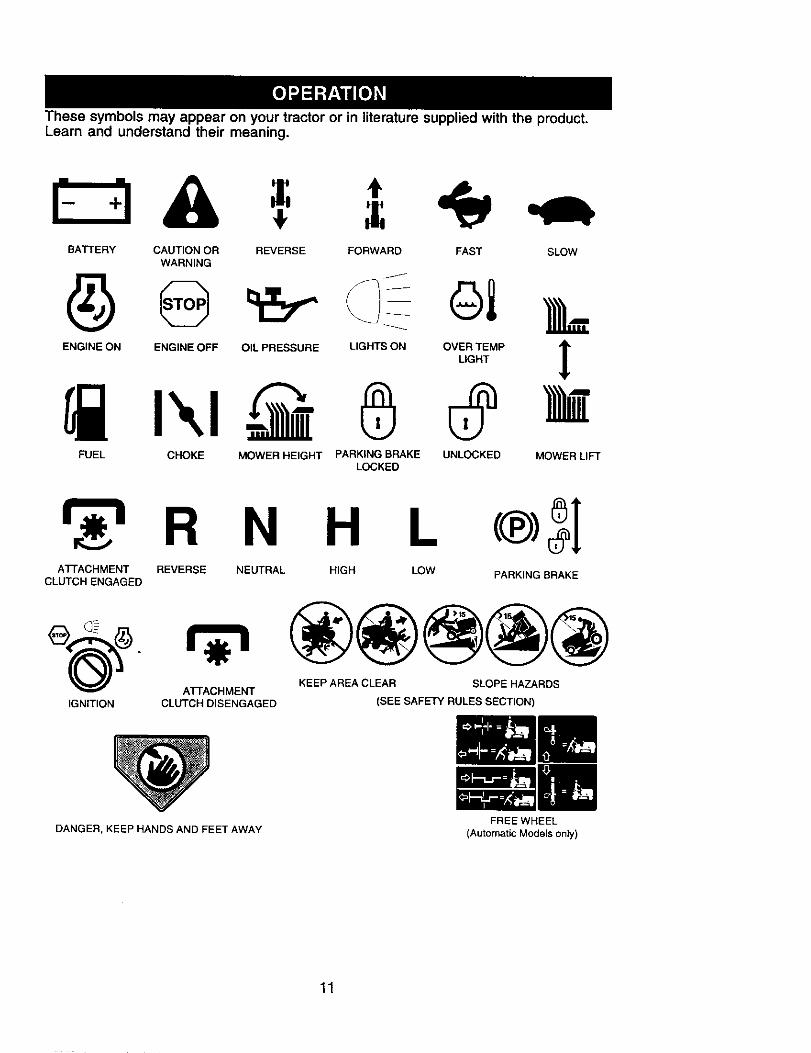
These symbols may appear on your tractor or in literature supplied with the _roduct.Learn and understand their meaning.
BATTERY CAUTION OR REVERSE FORWARD FAST SLOWWARNING
ENGINE ON ENGINE OFF OIL PRESSURE LIGHTS ON OVER TEMPLIGHT
R N H L c® 31ATTACHMENT REVERSE NEUTRAL HIGH LOW PARKING BRAKE
CLUTCH ENGAGED
IGNITION
KEEP AREA CLEAR SLOPE HAZARDSATTACHMENT
CLUTCH DISENGAGED (SEE SAFETY RULES SECTION)
DANGER, KEEP HANDS AND FEET AWAY
11
FREE WHEEL
(Automatic Models only)
KNOW YOUR TRACTOR
READ THIS OWNER'S MANUAL AND SAFETY RULES BEFORE OPERATINGYOUR TRACTOR
Compare the illustrations with your tractor to familiarize yourself with the locations ofvarious controls and adjustments. Save this manual for future reference.
Ammeter
Attachment
Clutch Ignition SwitchLever
Position
Throttle/ChokeLeverPlunger
AttachmentLift Lever
Clutch/ Height
Brake Pedal Indicator
g Brake Lever
Gearshift \Our tractors conform to the safety standards of the
American National Standards Institute.
ATTACHMENT CLUTCH LEVER - Usedto engage the mower blades, or otherattachments mounted to your tractor.ATTACHMENT LIFT LEVER - Used toraise, lower, and adjust the mower deckor other attachments mounted to yourtractor.CLUTCH/BRAKE PEDAL - Used fordeclutching and braking the tractor andstarting the engine.GEARSHIFT LEVER - Selects the speedand direction of tractor.
IGNITION SWITCH - Used for starting andstopping the engine.LIFT LEVER PLUNGER - Used to releaseattachment lift lever when changing itsposition.LIGHT SWITCH POSITION - Turns theheadlights on and off.PARKING BRAKE LEVER - Locks clutch/brake pedal into the brake position.THROTTLE/CHOKE CONTROL - Used
for starting and controlling engine speed.AMMETER - Indicates battery charging(+) or discharging (-).
12
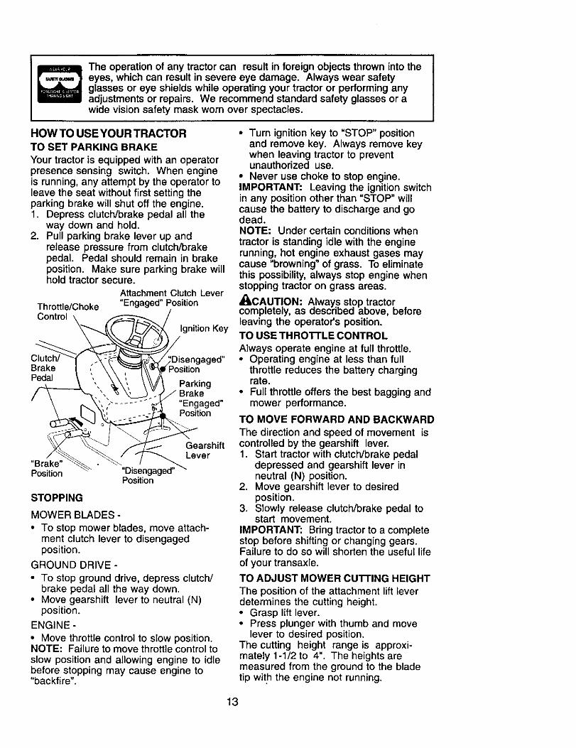
The operation of any tractor can result in foreign objects thrown into theeyes, which can result in severe eye damage. Always wear safetyglasses or eye shields while operating your tractor or performing anyadjustments or repairs. We recommend standard safety glasses or awide vision safety mask worn over spectacles.
HOW TO USE YOUR TRACTOR
TO SET PARKING BRAKE
Your tractor is equipped with an operatorpresence sensing switch. When engineis running, any attempt by the operator toleave the seat without first setting theparking brake will shut off the engine.1. Depress clutch/brake pedal all the
way down and hold.2. Pull parking brake lever up and
release pressure from clutch/brakepedal. Pedal should remain in brakeposition. Make sure parking brake willhold tractor secure.
Throttle/ChokeControl
Attachment Clutch Lever"Engaged" Position
Ignition Key
BrakePedal
led"
ParkingBrake"Engaged"Position
GearshiftLever
"Brake"Position "Disengag ed"_
Position
STOPPING
MOWER BLADES -
• To stop mower blades, move attach-ment clutch lever to disengagedposition.
GROUND DRIVE -
• To stop ground drive, depress clutch/brake pedal all the way down.
• Move gearshift lever to neutral (N)position.
ENGINE -
• Move throttle control to slow position.NOTE: Failure to move throttle control toslow position and allowing engine to idlebefore stopping may cause engine to"backfire".
• Turn ignition key to "STOP" positionand remove key. Always remove keywhen leaving tractor to preventunauthorized use.
• Never use choke to stop engine.IMPORTANT: Leaving the ignition switchin any position other than "STOP" willcause the battery to discharge and godead.NOTE: Under certain conditions when
tractor is standing idle with the enginerunning, hot engine exhaust gases maycause "browning" of grass. To eliminatethis possibility, always stop engine whenstopping tractor on grass areas.
_CAUT!ON: Always stop tractor .completely, as aescribed above, eemreleaving the operator's position.TO USE THRO'n'LE CONTROL
Always operate engine at full throttle.• Operating engine at less than full
throttle reduces the battery chargingrate.
• Full throttle offers the best bagging andmower performance.
TO MOVE FORWARD AND BACKWARD
The direction and speed of movement iscontrolled by the gearshift lever.1. Start tractor with clutch/brake pedal
depressed and gearshift lever inneutral (N) position.
IMPORTANT: Bring tractor to a completestop before shifting or changing gears.Failure to do so will shorten the useful lifeof your transaxle.
TO ADJUST MOWER CU'R'ING HEIGHT
The position of the attachment lift leverdetermines the cutting height.• Grasp lift lever.• Press plunger with thumb and move
lever to desired position.The cutting height range is approxi-mately 1-1/2 to 4". The heights aremeasured from the ground to the bladetip with the engine not running.
13
These heights are approximate and mayvary depending upon soil conditions,height of grass and types of grass beingmowed.
• The average lawn should be cut toapproximately 2-1/2 inches during thecool season and to over 3 inchesduring hot months. For healthier andbetter looking lawns, mow often andafter moderate growth.
• For best cutting performance, grassover 6 inches in height should bemowed twice. Make the first cutrelatively high; the second to desiredheight.
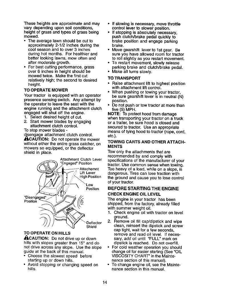
TO OPERATE MOWER
Your tractor is equipped with an operatorpresence sensing switch. Any attempt bythe operator to leave the seat with theengine running and the attachment clutchengaged will shut off the engine.1. Select desired height of cut.2. Start mower blades by engaging
CAUTION: Do not operate the mowerwithout either the entire grass catcher, onmowers so equipped, or the deflectorshield in place.
Attachment Clutch LoverPosition
AttachomntLift LeverHigh Position
Position
Position
_ctorShield
TO OPERATE ON HILLS
_CAUTION: Do not drive up or downhills with slopes greater than 15 ° and donot drive across any slope. Use the slopeguide at the back of this manual.• Choose the slowest speed before
starting up or down hills.• Avoid stopping or changing speed on
hills.
• If slowing is necessary, move throttlecontrol lever to slower position.
• If stopping is absolutely necessary,push clutch/brake pedal quickly tobrake position and engage parkingbrake.
• Move gearshift lever to lst gear. Besure you have allowed room for tractorto roll slightly as you restart movement.
• To restart movement, slowly releaseparking brake and clutch/brake pedal.
• Make all turns slowly.
TO TRANSPORT
• Raise attachment lift to highest positionwith attachment lift control.
• When pushing or towing your tractor,be sure gearshift lever is in neutral (N)position.
• Do not push or tow tractor at more thanfive (5) MPH.
NOTE: To protect hood from damagewhen transporting your tractor on a truckor a trailer, be sure hood is closed andsecured to tractor. Use an appropriatemeans of tying hood to tractor (rope, cord,etc.).
TOWING CARTS AND OTHER ATTACH-MENTS
Tow only the attachments that arerecommended by and comply withspecifications of the manufacturer of yourtractor. Use common sense when towing.Too heavy of a load, while on a slope, isdangerous. Tires can lose traction withthe ground and cause you to lose controlof your tractor.
BEFORE STARTING THE ENGINECHECK ENGINE OIL LEVEL
The engine in your tractor has beenshipped, from the factory, already filledwith summer weight oil.1. Check engine oil with tractor on level
ground.2. Remove oil fill cap/dipstick and wipe
clean, reinsert the dipstick and screwcap tight, wait for a few seconds,remove and read oil level. If neces-sary, add oil until "FULL" mark ondipstick is reached. Do not overfill.
• For cold weather operation you shouldchange oil for easier starting (See "OILVISCOSITY CHART" in the Mainte-nance section of this manual).
• To change engine oil, see the Mainte-nance section in this manual.
14
ADD GASOLINE• Fill fuel tank to bottom of tank filler
neck. Do not overfill. Use fresh, clean,regular unleaded gasoline with aminimum of 87 octane. (Use of leadedgasoline will increase carbon and leadoxide deposits and reduce valve life).Do not mix oil with gasoline. Purchasefuel in quantities that can be usedwithin 30 days to assure fuel freshness.
• 1,CAUTION: Wipe off any spilled oil orfuel. Do not store, spill or use gasolinenear an open flame.
IMPORTANT: When operating intemperatures below 32°F(0°C), use fresh,clean winter grade gasoline to helpinsure good cold weather starting.
CAUTION: Alcohol blended fuels
(called gasohol or using ethanol ormethanol) can attract moisture whichleads to separation and formation ofacids during storage. Acidic gas candamage the fuel system of an enginewhile in storage. To avoid engineproblems, the fuel system should beemptied before storage of 30 days orlonger. Drain the gas tank, start theengine and let it run until the fuel linesand carburetor are empty. Use fresh fuelnext season. See Storage Instructions foradditional information. Never use engineor carburetor cleaner products in the fueltank or permanent damage may occur.
TO START ENGINE
When starting the engine for the first timeor if the engine has run out of fuel, it willtake extra cranking time to move fuel fromthe tank to the engine.1. Sit on seat in operating position,
depress clutch/brake pedal and setparking brake.
2. Place gear shift lever in neutral (N)position.
3. Move attachment clutch to disen-gaged position.
4. Move throttle control to choke position.NOTE: Before starting, read the warmand cold starting procedures below.
. Insert key into ignition and turn keyclockwise to start position and releasekey as soon as engine starts. Do notrun starter continuously for more thanfifteen seconds per minute. If theengine does not start after severalattempts, move throttle control to fastposition, wait a few minutes and tryagain. If engine still does not start,move the throttle control back to the
choke position and retry.
WARM WEATHER STARTING (50 ° F andabove)6. When engine starts, move the throttle
control to the fast position.• The attachments and ground drive can
now be used. If the engine does notaccept the load, restart the engine andallow it to warm up for one minuteusing the choke as described above.
COLD WEATHER STARTING ( 50 ° F andbelow)
6. When engine starts, allow engine torun with the throttle control in thechoke position until the engine runsroughly, then move throttle control tofast position. This may require anengine warm-up period from severalseconds to several minutes, depend-ing on the temperature.
• The attachments can also be usedduring the engine warm-up period.
NOTE: If at a high altitude (above 3000feet) or in cold temperatures (below 32 F)the carburetor fuel mixture may need tobe adjusted for best engine performance.(See 'qO ADJUST CARBURETOR" in theService and Adjustments section of thismanual).
15
MOWING TIPS
• Mower should be properly leveled forbest mowing performance. See "TOLEVEL MOWER HOUSING" in theService and Adjustments section of thismanual.
• The left hand side of mower should beused for trimming.
• Drive so that clippings are dischargedonto the area that has already beencut. Have the cut area to the right of thetractor. This will result in a more even
distribution of clippings and moreuniform cutting.
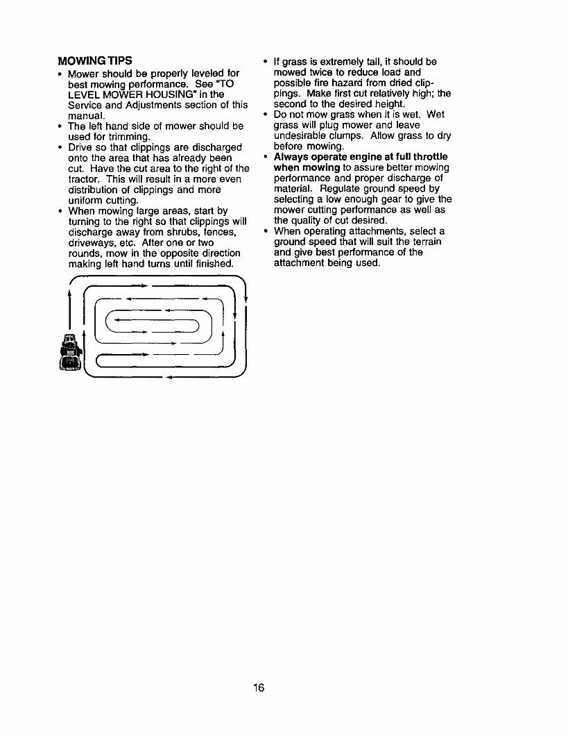
• When mowing large areas, start byturning to the right so that clippings willdischarge away from shrubs, fences,driveways, etc. After one or tworounds, mow in the opposite directionmaking left hand turns until finished.
f
]l
]=f
JJ
• If grass is extremely tall, it should bemowed twice to reduce load andpossible fire hazard from dried clip-pings. Make first cut relatively high; thesecond to the desired height.
• Do not mow grass when it is wet. Wetgrass will plug mower and leaveundesirable clumps. Allow grass to drybefore mowing.
• Always operate engine at full throttlewhen mowing to assure better mowingperformance and proper discharge ofmaterial. Regulate ground speed byselecting a low enough gear to give themower cutting performance as well asthe quality of cut desired.
• When operating attachments, select aground speed that will suit the terrainand give best performance of theattachment being used.
16
FILL IN DATES
REaU .SERV,OE ERV,CEDATES
Check Brake Operation If V'
Check Tire Pressure IfCheck Operator Presence and
T Interlock Systems I_
R Check for Loose Fasteners ik/ I_s If I
A SharpergReplace Mower Blades i _ V*
T Lubncation Chart
0 Check Battery Level IR Clean Battery and Terminals If i
NI Inspect Mutfler/Spark Arrester JE Replace Oil Filter (If equipped) 11_1,:
Clean Engine Cooling Fins I_
Replace Spark Plug _/2Replace Air Filter Paper Cadridge
Replace Fuel Filter I_
1 * Change rnorw onen when opelat_g under a hen W _oad orin high ambient temperatures.
2 o Service more often when operating in dirty or dusty conditions.
3 * Replace blades more often when mowing in sandy soil.4 - Not required if equipped with maJnter_nce-free battery.5 - ]3ghten front axle pivot bOlt to 35 It.-Ib$. maximum,
DO not overlighten.
GENERAL RECOMMENDATIONS
The warranty on this tractor does notcover items that have been subjected tooperator abuse or negligence. Toreceive full value from the warranty,operator must maintain tractor asinstructed in tl).is manual.Some adjustments will need to be madeperiodically to properly maintain yourtractor.All adjustments in the Service andAdjustments section of this manualshould be checked at least once eachseason.• Once a year you should replace the
spark plug, clean or replace air filter,and check blades and belts for wear.A new spark plug and clean air filterassure proper air-fuel mixture andhelp your engine run better and lastlonger.
interlock systems for proper operation.5. Check for loose fasteners.
LUBRICATION CHART
Spindle --Zerk Zerk
(_Front WheelBearingZerk
Bearing Zerk
E
_) General Purpose Grease(_ Refer to Maintenance "ENGINE"
Section
IMPORTANT: Do not oil or grease the pivotpoints which have special nylon bearings.Viscous lubricants will attract dust and dirtthat will shorten the life of the self-lubricat-ing bearings. If you feel they must belubricated, use only a dry, powderedgraphite type lubricant sparingly.
17
TRACTOR
Always observe safety rules whenperforming any maintenance.
BRAKE OPERATION
If tractor requires more than six (6) feetstopping distance at high speed inhighest gear, then brake must be ad-justed. (See "TO ADJUST BRAKE" in theService and Adjustments section of thismanual).
TIRES
• Maintain proper air pressure in all tires(See "PRODUCT SPECIFICATIONS"section of this manual).
• Keep tires free of gasoline, oil, or insectcontrol chemicals which can harmrubber.
• Avoid stumps, stones, deep ruts, sharpobjects and other hazards that maycause tire damage.
NOTE: To seal tire punctures and preventflat tires due to slow leaks, tire sealantmay be purchased from your local partsdealer. Tire sealant also prevents tire dryrot and corrosion.OPERATOR PRESENCE SYSTEM
Be sure operator presence and interlocksystems are working properly. If yourtractor does not function as described,repair the problem immediately• The engine should not start unless the
clutch/brake pedal is fully depressedand attachement clutch control is in thedisengaged position.
• When the engine is running, anyattempt by the operator to leave theseat without first setting the parkingbrake should shut off the engine.
• When the engine is running and theattachment clutch is engaged, anyattempt by the operator to leave theseat should shut off the engine.
• The attachment clutch should neveroperate unless the operator is in theseat.
BLADE CARE
For best results mower blades must bekept sharp. Replace bent or damagedblades.
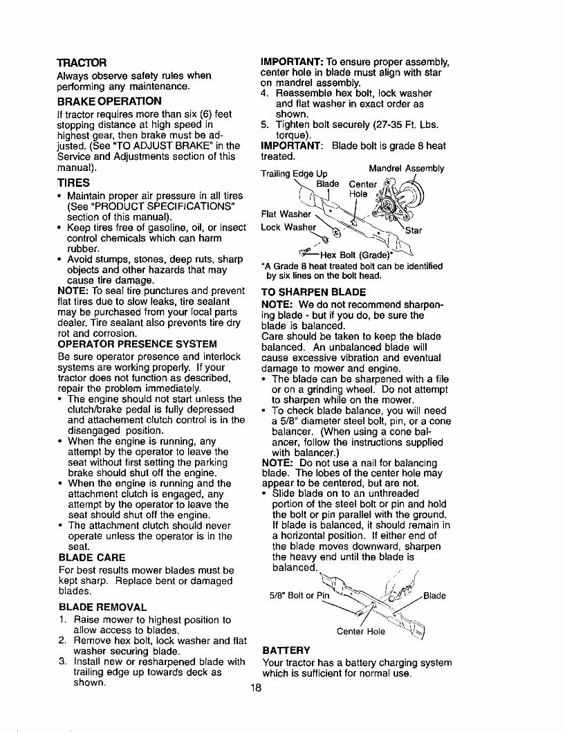
BLADE REMOVAL
1. Raise mower to highest position toallow access to blades.
2. Remove hex bolt, lock washer and flatwasher securing blade.
3. Install new or resharpened blade withtrailing edge up towards deck as
IMPORTANT: To ensure proper assembly,center hole in blade must align with staron mandrel assembly.4. Reassemble hex bolt, lock washer
and flat washer in exact order asshown.
5. Tighten bolt securely (27-35 Ft. Lbs.torque).
IMPORTANT:treated.
Trailing I
Blade bolt is grade 8 heat
Mandrel Assembly
CenterHole
Flat Washer \Lock Washer
_-_--Hex Bolt (Grade)'*A Grade 8 heat treated bolt can be identified
by six lines on the bolt head.
TO SHARPEN BLADE
NOTE: We do not recommend sharpen-ing blade - but if you do, be sure theblade is balanced.Care should be taken to keep the bladebalanced. An unbalanced blade willcause excessive vibration and eventualdamage to mower and engine.• The blade can be sharpened with a file
or on a grinding wheel. Do not attemptto sharpen while on the mower.
• To check blade balance, you will needa 5/8" diameter steel bolt, pin, or a conebalancer. (When using a cone bal-ancer, follow the instructions suppliedwith balancer.)
NOTE: Do not use a nail for balancingblade. The lobes of the center hole mayappear to be centered, but are not.• Slide blade on to an unthreaded
portion of the steel bolt or pin and holdthe bolt or pin parallel with the ground.If blade is balanced, it should remain ina horizontal position. If either end ofthe blade moves downward, sharpenthe heavy end until the blade isbalanced.
5/8" Bolt or Pin
Center Hole
BATTERY
Your tractor has a battery charging systemwhich is sufficient for normal use
shown. 18
However, periodic charging of the batterywith an automotive charger will extend itslife.• Keep battery and terminals clean.• Keep battery bolts tight.• Keep small vent holes open.• Recharge at 6-10 amperes for 1 hour.NOTE: The original equipment battery onyour tractor is maintenance free. Do notattempt to open or remove caps or covers.Adding or checking level of electrolyte isnot necessary.TO CLEAN BATTERY AND TERMINALS
Corrosion and dirt on the battery andterminals can cause the battery to "leak"power.1. Open battery box door.2. Disconnect BLACK battery cable first
then RED battery cable and removebattery from tractor.
3. Rinse the battery with plain water anddry.
4. Clean terminals and battery cableends with wire brush until bright.
5. Coat terminals with grease or petro-leum jelly.
6. Reinstall battery (See "REPLACINGBATTERY" in the SERVICE ANDADJUSTMENTS section of thismanual).
TRANSAXLE COOLING
Keep transaxle free from build-up of dirtand chaff which can restrict cooling.V-BELTS
Check V-belts for deterioration and wearafter 100 hours of operation and replaceif necessary. The belts are not adjustable.Replace belts if they begin to slip fromwear.
ENGINE
LUBRICATION
Only use high quality detergent oil ratedwith API service classification SF-SJSelect the oil's SAE viscosity gradeaccording to your expected operatingtemperature.
SAE VISCOSITY GRADES
F _ _ ,
.3O .to 0TEMPERATURE RANGE ANTICIPATED BEFORE N_XT OIL C_;ANGE
NOTE: Although multi-viscosity oils(5W30, 10W30 etc.) improve starting incold weather, these multi-viscosity oilswill result in increased oil consumptionwhen used above 32°F.
Check your engine oil level morefrequently to avoid possible enginedamage from running low on oil.Change the oil after every 25 hours ofoperation or at least once a year if thetractor is not used for 25 hours in oneyear.Check the crankcase oil level beforestarting the engine and after each eight(8) hours of operation. Tighten oil fill cap/dipstick securely each time you check theoil level.TO CHANGE ENGINE OIL
Determine temperature range expectedbefore oil change. All oil must meet APIservice classification SF-SJ.• Be sure tractor is on level surface.• Oil will drain more freely when warm.• Catch oil in a suitable container.1. Remove oil fill cap/dipstick. Be careful
not to allow dirt to enter the enginewhen changing oil.
2. Remove yellow cap from end of drainvalve and install the drain tube ontothe fitting.
Oil Drain Valve
Closed andLocked _ b
Position [Yellow L-,
Cap _
DrainTube
/
3. Unlock drain valve by pushing inwardslightly and turning counterclockwise.
4. To open, pull out on the drain valve.5. After oil has drained completely, close
and lock the drain valve by pushinginward and turning clockwise until thepin is in the locked position as shown.
6. Remove the drain tube and replacethe cap onto the end of the drainvalve.
7. Refill engine with oil through oil filldipstick tube. Pour slowly. Do notoverfill. For approximate capacity see"PRODUCT SPECIFICATIONS"section of this manual.
8. Use gauge on oil fill cap/dipstick forchecking level. For accurate reading,tighten dipstick cap securely onto thetube before removing dipstick. Keepoil at "FULL" line on dipstick. Tightencap onto the tube securely whenfinished.
19
AIR FILTER
Your engine will not run properly using adirty air filter. Clean the foam pre-cleanerafter every 25 hours of operation or everyseason. Service paper cartridge every100 hours of operation or every season,whichever occurs first.Service air cleaner more often underdusty conditions.1. Remove knob(s) and cover.
TO SERVICE PRE-CLEANER
2. Slide foam pre-cleaner off cartridge. 4.3. Wash it in liquid detergent and water.4. Squeeze it dry in a clean cloth.5. Saturate it in engine oil. Wrap it in Screws
clean, absorbent cloth and squeeze toremove excess oil.
NOTE" If very dirty or damaged, replacepre-cleaner.6. Reinstall pre-cieaner over cartridge.7. Reinstall cover and secure with Di
knob(s). Assembly
TO SERVICE CARTRIDGE
1. Remove cartridge nut.2. Carefully remove cartddge to prevent
debris from entering carburetor.Clean base carefully to prevent debrisfrom entering carburetor.
3. Clean cartridge by tapping gently onflat surface.
NOTE- If very dirty or damaged, replacecartridge.4. Reinstall cartridge, nut, precleaner,
cover and secure with knob(s).IMPORTANT" Petroleum solvents, suchas kerosene, are not to be used to cleanthe cartridge. They may cause deteriora-tion of the cartridge. Do not oil cartridge.Do not use pressurized air to clean or drycartridge.
Cover Kno . .;over
CLEAN AIR SCREEN
Air screen must be kept free of dirt andchaff to prevent engine damage fromoverheating. Clean with a wire brush orcompressed air to remove dirt andstubborn dried gum fibers.
ENGINE COOLING FINS
Remove any dust, dirt or oil from enginecooling fins to prevent engine damagefrom overheating.1. Remove screws from blower housing
and lift housing and dipstick tubeassembly off engine.
2. Cover oil fill opening to prevent entryof dirt.
3. Use compressed air or stiff bristlebrush to thoroughly clean enginecooling fins.To reassemble, reverse aboveprocedure.
Blower Housing Screws
PlugEngine Cooling Fins
MUFFLER
Inspect and replace corroded muffler andspark arrester (if equipped) as it couldcreate a fire hazard and/or damage.SPARK PLUG(S)Replace spark plug(s) at the beginning ofeach mowing season or after every 100hours of operation, whichever occurs first.Spark plug type and gap setting areshown in "PRODUCT SPECIFICATIONS"section of this manual.
IN-LINE FUEL FILTER
The fuel filter should be replaced onceeach season. If fuel filter becomesclogged, obstructing fuel flow to carbure-tor, replacement is required.1. With engine cool, remove filter and
plug fuel line sections.2. Place new fuel filter in position in fuel
line with arrow pointing towardscarburetor.
3. Be sure there are no fuel line leaksand clamps are properly positioned.
4. Immediately wipe up any spilled
gasoline. Clamp
Fuel Filter_
2O
CLEANING
• Clean engine, battery, seat, finish, etc.of all foreign matter.
• Keep finished surfaces and wheels freeof all gasoline, oil, etc.
• Protect painted surfaces with automo-tive type wax.
We do not recommend using a gardenhose to clean your tractor unless theelectrical system, muffler, air filter andcarburetor are covered to keep water out.Water in engine can result in a shortenedengine life.
WARNING: TO AVOID SERIOUS INJURY, BEFORE PERFORMING ANY
SERVICE OR ADJUSTMENTS:
1. Depress clutch/brake pedal fully and set parking brake.2. Place gearshift lever in neutral (N) position.3. Place attachment clutch in "DISENGAGED" position.4. Turn ignition key to "STOP" and remove key.5. Make sure the blades and all moving parts have completely stopped.6. Disconnect spark plug wire from spark plug and place wire where it cannot
come in contact with plu 9.
TRACTORTO REMOVE MOWER
Mower will be easier to remove from theright side of tractor.1. Place attachment clutch in "DISEN-
GAGED" position.2. Move attachment lift lever forward to
lower mower to its lowest position.3. Roll belt off engine pulley.4. Remove small retainer spring, and lift
clutch spring off pulley bolt.5. Remove large retainer spring, slide
collar off and push housing guide outof bracket.
6. Disconnect anti-sway bar from chassisbracket by removing retainer spring.
7. Disconnect suspension arms fromrear deck brackets by removingretainer springs.
8. Disconnect front links from deck byremoving retainer springs.
Small Retainer Spring
Clutch Spring_
9. Raise lift lever to raise suspensionarms. Slide mower out from undertractor.
IMPORTANT: If an attachment other thanthe mower deck is to be mounted on thetractor, remove the front links and hookthe clutch spring Into square hole inframe.
TO INSTALL MOWER
1. Raise attachment lift lever to itshighest position.
2. Slide mower under tractor withdeflector shield to right side of tractor.
3. Lower lift lever to its lowest position.4. Connect front links to mower deck and
secure with retainer springs.
- . Square HoleSuspension Arms ,.'line Pulley
Retainer
Anti*Sway
Link
Retainer Springs(Both Sides)
Housing Guide Brac
Large Retainer Spring21
5. Connectsuspension arms to reardeck brackets and secure withretainer springs.
6. Connect anti-sway bar to chassisbracket and secure with retainerspring.
7. Push clutch cable housing guide intobracket, slide collar onto guide andsecure with large retainer spring.
8. Install belt onto engine pulley.
TO LEVEL MOWER HOUSING
Adjust the mower while tractor is parkedon level ground or driveway. Make suretires are properly inflated (See "PROD-UCT SPECIFICATIONS" section of thismanual). If tires are over orunderinflated, you will not properly adjustyour mower.
SIDE-TO-SIDE ADJUSTMENT
• Raise mower to its highest position.• At the midpoint of both sides of mower,
measure height from bottom edge ofmower to ground. Distance "A" onboth sides of mower should be thesame or within 1/4" of each other.
• If adjustment is necessary, makeadjustment on one side of mower only.
• To raise one side of mower, tighten liftlink adjustment nut on that side.
• To lower one side of mower, loosen liftlink adjustment nut on that side.
NOTE: Each full turn of adjustment nutwill change mower height about 1/8".• Recheck measurements after adjust-
ing.
Bottom edge of Bottom edge ofmower to ground mower to ground
,_, Suspension Arm
Lift Link Adjustment Nut
FRONT-TO-BACK ADJUSTMENTIMPORTANT: Deck must be level side-toside. If the following front-to-back adjust-ment is necessary, be sure to adjust bothfront links equally so mower will stay levelside-to-side.To obtain the best cutting results, themower housing should be adjusted sothat the front is approximately 1/8" to 1/2"lower than the rear when the mower is inits highest position.Check adjustment on right side of tractor.Measure distance "D" directly in front andbehind the mandrel at bottom edge ofmower housing as shown.• Before making any necessary adjust-
ments, check that both front links areequal in length.
• If links are not equal in length, adjustone link to same length as other link.
• To lower front of mower loosen nut "E"on both front links an equal number ofturns.
• When distance "D" is 1/8" to 1/2" lowerat front than rear, tighten nuts "F"against trunnion on both front links.
• To raise front of mower, loosen nut "F"from trunnion on both front links.Tighten nut "E" on both front links anequal number of turns. The two frontlinks must remain equal in length.
• When distance "D" is 1/8" to 1/2" lowerat front than rear, tighten nut "F" againsttrunnion on both front links.
• Recheck side-to-side adjustment.
Both Front Links Should be Equal in Length
Nut "E"
ront Links/
22
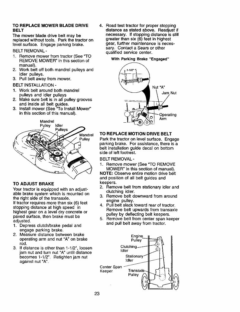
TO REPLACE MOWER BLADE DRIVEBELT
The mower blade drive belt may bereplaced without tools. Park the tractor onlevel surface. Engage parking brake.
BELT REMOVAL -
1. Remove mower from tractor (See "TOREMOVE MOWER" in this section ofmanual).
2. Work belt off both mandrel pulleys andidler pulleys.
3. Pull belt away from mower.
BELT INSTALLATION -1. Work belt around both mandrel
pulleys and idler pulleys2. Make sure belt is in all pulley grooves
and inside all belt guides.3. Install mower (See "To Install Mower"
in this section of this manual).
MandrelPuLley Idler
Pulle
_ndrelPulley
TO ADJUST BRAKE
Your tractor is equipped with an adjust-able brake system which is mounted onthe right side of the transaxle.If tractor requires more than six (6) feetstopping distance at high speed inhighest gear on a level dry concrete orpaved surface, then brake must beadjusted.1. Depress clutch/brake pedal and
engage parking brake.2. Measure distance between brake
operating arm and nut "A" on brakerod.
3. If distance is other than 1-1/2", loosenjam nut and turn nut "A" until distancebecomes 1-1/2". Retighten jam nutagainst nut "A".
4. Road test tractor for proper stoppingdistance as stated above. Readjust ifnecessary. If stopping distance is stillgreater than six (6) feet in highestgear, further maintenance is neces-sary. Contact a Sears or otherqualified service center.
With Parking Brake "Engaged"
Nut =A"
Nut
ting
Arm
TO REPLACE MOTION DRIVE BELT
Park the tractor on level surface. Engageparking brake. For assistance, there is abelt installation guide decal on bottomside of left footrest.
BELT REMOVAL-
1. Remove mower (See "TO REMOVEMOWER" in this section of manual).
NOTE: Observe entire motion drive beltand position of all belt guides andkeepers.2. Remove belt from stationary idler and
clutching idler.3. Remove belt downward from around
engine pulley.4. Pull belt slack toward rear of tractor.
Remove belt upwards from transaxlepulley by deflecting belt keepers.
5. Remove belt from center span keeperand pull belt away from tractor.
ER '
Pulley
Idler
StationarIdler
Center SpanKeeper Transaxl,
Pulley
23
BELT INSTALLATION -
1. Carefully work new belt down be-tween transaxle belt keepers and ontothe input pulley.
2. Slide belt into the center span keeper.3. Pull belt toward front of tractor and roll
around the top groove of enginepulley.
4. Install belt through stationary idler andclutching idler.
5. Make sure belt is in all pulley groovesand inside all belt guides and keep-ers.
6. Install mower (See "TO INSTALLMOWER" in this section of manual).
TO ADJUST STEERING WHEEL ALIGN-MENT
If steering wheel crossbars are nothorizontal (left to right) when wheels arepositioned straight forward, removesteering wheel and reassemble withcrossbars horizontal. Tighten securely.FRONT WHEEL TOE-IN/CAMBER
The front wheel toe-in and camber arenot adjustable on your tractor. If damagehas occurred to affect the front wheel toe-in or camber, contact a Sears or otherqualified service center.TO REMOVE WHEEL FOR REPAIRS
1. Block up axle securely.2. Remove axle cover, retaining ring and
washers to allow wheel removal (rearwheels have a square key - Do notlose).
3. Repair tire and reassemble.NOTE: On rear wheels only: aligngrooves in rear wheel hub and axle.Insert square key.4. Replace washers and snap retaining
ring securely in axle groove.5. Replace axle cover.NOTE: To seal tire punctures and preventflat tires due to slow leaks, purchase anduse tire sealant from Sears. Tire sealantalso prevents tire dry rot and corrosion.
Washers
RetainingRing
AxleCover
TO START ENGINE WITH A WEAK
RNING: Lead-acid batteriesgenerate explosive gases. Keep sparks,flame and smoking materials away frombatteries. Always wear eye protectionwhen around batteries.If your battery is too weak to start theengine, it should be recharged. (See"BA'I-IERY" in the MAINTENANCEsection of this manual).If "jumper cables" are used for emergencystarting, follow this procedure:IMPORTANT: Your tractor is equippedwith a 12 volt system. The other vehiclemust also be a 12 volt system. Do not useyour tractor battery to start other vehicles.
TO A-I-I-ACH JUMPER CABLES -
1. Connect one end of the RED cable tothe POSITIVE (+) terminal of eachbattery(A-B), taking care not to shortagainst tractor chassis.
2. Connect one end of the BLACK cable
to the NEGATIVE (-) terminal (C) offully charged battery.
3. Connect the other end of the BLACKcable (D) to good chassis ground,away from fuel tank and battery.
TO REMOVE CABLES, REVERSEORDER -
1. BLACK cable first from chassis andthen from the fully charged battery.
2. RED cable last from both batteries.
Weak or Dead Fully ChargedBattery Battery
Square Key - '(Rear Wheel Only) _ ....
24
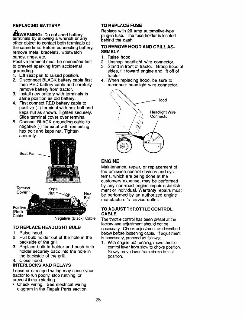
REPLACING BATTERY
4_LWARNING: Do not short b,atteryterminals oy allowing a wrencn or anyother object to contact both terminals atthe same time. Before connecting battery,remove metal bracelets, wristwatchbands, rings, etc.Positive terminal must be connected firstto prevent sparking from accidentalgrounding.1. Lift seat pan to raised position.2. Disconnect BLACK battery cable first
then RED battery cable and carefullyremove battery from tractor.
3. Install new battery with terminals insame position as old battery.
4. First connect RED battery cable topositive (+) terminal with hex bolt andkeps nut as shown. Tighten securely.Slide terminal cover over terminal
5. Connect BLACK grounding cable tonegative (-) terminal with remaininghex bolt and keps nut. Tightensecurely.
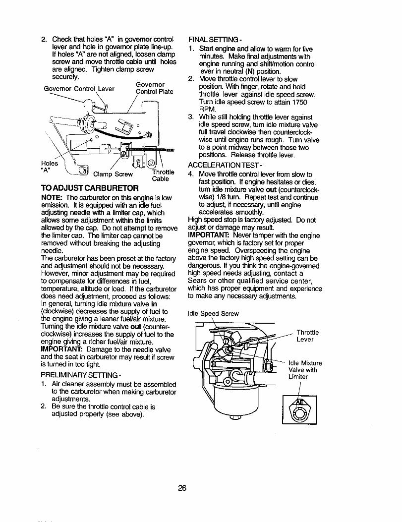
TO REPLACE FUSE
Replace with 20 amp automotive-typeplug-in fuse. The fuse holder is locatedbehind the dash.
TO REMOVE HOOD AND GRILL AS-SEMBLY1. Raise hood.
2. Unsnap headlight wire connector.3. Stand in front of tractor. Grasp hood at
sides, tilt toward engine and lift off oftractor.
4. When replacing hood, be sure toreconnect headlight wire connector.
\
\\
Headlight WireConnector
Seat Pan
Terminal KepsCover Hex
Bolt
Positive,(Red)Cable
Negative (Black) Cable
TO REPLACE HEADLIGHT BULB
1. Raise hood.2. Pull bulb holder out of the hole in the
backside of the grill.3. Replace bulb in holder and push bulb
holder securely back into the hole inthe backside of the grill.
4. Close hood.INTERLOCKS AND RELAYS
Loose or damaged wiring may cause yourtractor to run poorly, stop running, orprevent it from starting.• Check wiring. See electrical wiring
diagram in the Repair Parts section.
ENGINE
Maintenance, repair, or replacement ofthe emission control devices and sys-tems, which are being done at thecustomers expense, may be performedby any non-road engine repair establish-ment or individual. Warranty repairs mustbe performed by an authorized enginemanufacturer's service outlet.
TO ADJUST THROTTLE CONTROLCABLE
The throttle control has been preset at thefactory and adjustment should not benecessary. Check adjustment as describedbelow before loosening cable. If adjustmentis necessary, proceed as follows:1. With engine not running, move throttle
control lever from slow to choke position.Slowly move lever from choke to fastposition.
25
2. Check that holes "A" in governor controllever and hole in governor plate line-up.If holes "A" are not aligned, loosen clampscrew and move throttle cable until holesare aligned. Tighten clamp screwsecurely.
GovernorGovernor Control Lever Control Plate
Holes"A" _,
Clamp Screw ThrottleCable
TO ADJUST CARBURETOR
NOTE: The carburetor on this engine is lowemission. It is equipped with an idle fueladjusting needle with a limiter cap, whichallows some adjustment within the limitsallowed by the cap. Do not attempt to removethe limiter cap. The limiter cap cannot beremoved without breaking the adjustingneedle.The carburetor has been preset at the factoryand adjustment should not be necessary.However, minor adjustment may be requiredto compensate for differences in fuel,temperature, altitude or load. If the carburetordoes need adjustment, proceed as follows:In general, turning idle mixture valve in(clockwise) decreases the supply of fuel tothe engine giving a leaner fueVair mixture.Tuming the idle mixture valve out (counter-clockwise) increases the supply of fuel to theengine giving a richer fueVair mixture.IMPORTANT: Damage to the needle valveand the seat in carburetor may result if screwis turned in too tight.
PRELIMINARY SETTING -
1. Air cleaner assembly must be assembledto the carburetor when making carburetoradjustments.
2. Be sure the throttle control cable isadjusted properly (see above).
FINAL SE'FI'ING -
1. Start engine and allow to warm for fiveminutes. Make final adjustments withengine running and shift/motion controllever in neutral (N) position.
2. Move throttle control lever to slowposition. With finger, rotate and holdthrottle lever against idle speed screw.Turn idle speed screw to attain 1750RPM.
3. While still holding throttle lever againstidle speed screw, turn idle mixture valvefull travel clockwise then counterclock-wise until engine runs rough. Turn valveto a point midway between those twopositions. Release throttle lever.
ACCELERATION TEST-
4. Move throttle control lever from slow tofast position. If engine hesitates or dies,turn idle mixture valve out (counterclock-wise) 1/8 turn. Repeat test and continueto adjust, if necessary, untilengineaccelerates smoothly.
High speed stop is factory adjusted. Do notadjust or damage may result.IMPORTANT: Never tamper with the enginegovernor, which is factory set for properengine speed. Overspeeding the engineabove the factory high speed setting can bedangerous. If you think the engine-governedhigh speed needs adjusting, contact aSears or other qualified service center,which has proper equipment and experienceto make any necessary adjustments.
Idle Speed Screw
_ Throttle
_ Lever
[ [r]_ I ]I'F:___- Idle Mixture"-_ f._ Valve with
26
Immediately prepare your tractor forstorage at the end of the season or if thetractor will not be used for 30 days ormore.
_CAUTION: Never store the tractor withgasoline in the tank inside a buildingwhere fumes may reach an open flame orspark. Allow the engine to cool beforestoring in any enclosure.
TRACTORRemove mower from tractor for winterstorage. When mower is to be stored fora period of time, clean it thoroughly,remove all dirt, grease, leaves, etc. Storein a clean, dry area.1. Clean entire tractor (See "CLEANING"
in the Maintenance section of thismanual).
2. Inspect and replace belts, if necessary(See belt replacement instructions inthe Service and Adjustments sectionof this manual).
3. Lubricate as shown in the Mainte-nance section of this manual.
4. Be sure that all nuts, bolts and screwsare securely fastened. Inspect movingparts for damage, breakage and wear.Replace if necessary.
5. Touch up all rusted or chipped paintsurfaces; sand lightly before painting.
BATrERY
• Fully charge the battery for storage.• After a period of time in storage, battery
may require" recharging.• To help prevent corrosion and power
leakage during long periods of storage,battery cables should be disconnectedand battery cleaned thoroughly (see"TO CLEAN BATI-ERY AND TERMI-NALS" in the Maintenance section ofthis manual).
• After cleaning, leave cables discon-nected and place cables where theycannot come in contact with batteryterminals.
• If battery is removed from tractor forstorage, do not store battery directly onconcrete or damp surfaces.
ENGINE
FUEL SYSTEM
IMPORTANT: It is important to preventgum deposits from forming in essentialfuel system parts such as carburetor, fuelhose, or tank during storage.
Also, alcohol blended fuels (calledgasohol or using ethanol or methanol)can attract moisture which leads toseparation and formation of acids duringstorage. Acidic gas can damage the fuelsystem of an engine while in storage.1. Drain the fuel tank.2. Start the engine and let it run until the
fuel lines and carburetor are empty.• Never use engine or carburetor cleaner
products in the fuel tank or permanentdamage may occur.
• Use fresh fuel next season.NOTE: Fuel stabilizer is an acceptablealternative in minimizing the formation offuel gum deposits during storage. Addstabilizer to gasoline in fuel tank orstorage container. Always follow the mixratio found on stabilizer container. Run
engine at least 10 minutes after addingstabilizer to allow the stabilizer to reachthe carburetor. Do not drain the gas tankand carburetor if using fuel stabilizer.
ENGINE OILDrain oil (with engine warm) and replacewith clean engine oil. (See "ENGINE" inthe Maintenance section of this manual).
CYLINDER(S)
1. Remove spark plug(s).2. Pour one ounce of oil through spark
plug hole(s) into cylinder(s),3. Turn ignition key to start position for a
few seconds to distribute oil.
4. Replace with new spark plug(s).
OTHER
• Do not store gasoline from one seasonto another.
• Replace your gasoline can if your canstarts to rust. Rust and/or dirt in yourgasoline will cause problems.
• If possible, store your tractor indoorsand cover it to give protection from dustand dirt.
• Cover your tractor with a suitableprotective cover that does not retainmoisture. Do not use plastic. Plasticcannot breathe which allows conden-sation to form and will cause yourtractor to rust.
IMPORTANT: Never cover tractor whileengine and exhaust areas are still warm.
27
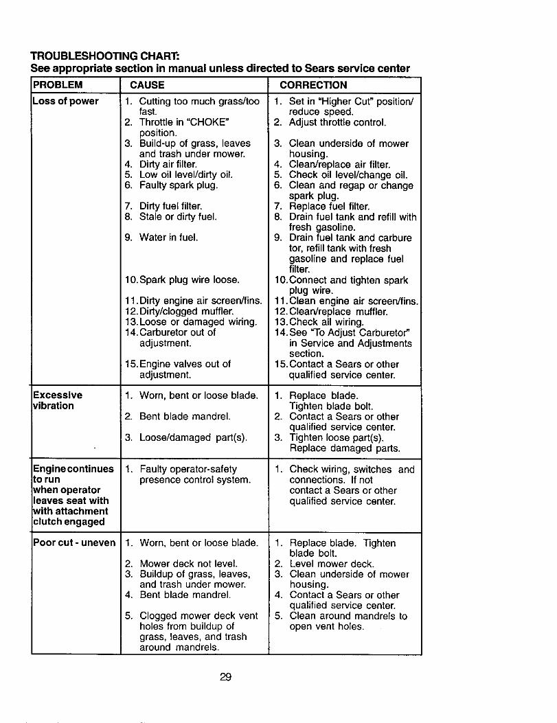
TROUBLESHOOTING CHART:See appropriate section in manual unless directed to Sears service center
PROBLEM CAUSE CORRECTION
Will not start
Hard to start
Enginewill notturn over
Engine clicks butwill not start
1. Out of fuel.
2. Engine not "CHOKED"properly.
3. Engine flooded.
.
5.6.7
.
Bad spark plug. 4.Dirty air filter. 5.Dirty fuel filter. 6.Water in fuel. 7.
8. Loose or damaged wiring.9. Carburetor out of adjustment.
10. Engine valves out ofadjustment.
1. Dirty air filter.2. Bad spark plug.3. Weak or dead battery.
4. Dirty fuel filter.5. Stale or dirty fuel.
Loose or damaged wiring. 6.Carburetor out of adjustment. 7.
.
7.
1. Fill fuel tank.2. See "TO START ENGINE"
in Operation section.Wait several minutesbefore attempting to start.Replace spark plug.Clean/replace air filter.Replace fuel filter.Drain fuel tank andcarburetor, refill tank withfresh gasoline and replacefuel filter.
8. Check all wiring.9. See "To Adjust Carburetor"
in Service and Adjustmentssection.
10. Contact a Sears or other
qualified service center.
8. Engine valves out ofadjustment.
Clutch/brake pedal notdepressed.Attachment clutch isengaged.Weak or dead battery.
Blown fuse.Corroded battery terminals.Loose or damaged wiring.Faulty ignition switch.
Faulty solenoid or starter.
Faulty operator presenceswitch(es).
.
2.
3.
4.5.6.7.
8.
9.
1. Weak or dead battery.2. Corroded battery terminals.3. Loose or damaged wiring.4. Faulty solenoid or starter.
1. Clean/replace air filter.2. Replace spark plug.3. Recharge or replace
battery.4. Replace fuel filter.5. Drain fuel tank and refill
with fresh gasoline.Check all wiring.See "To Adjust Carburetor"in Service and Adjustmentssection.
8. Contact a Sears or otherqualified service center.
Cutting too much grass/toofast.Throttle in "CHOKE"position.Build-up of grass, leaves 3.and trash under mower.Dirty air filter. 4.Low oil level/dirty oil. 5.Faulty spark plug. 6.
7.8.
9.
10.Spark plug wire loose.
1. Set in "Higher Cut" position/reduce speed.
2. Adjust throttle control.
Clean underside of mowerhousing.Clean/replace air filter.Check oil level/change oil.Clean and regap or changespark plug.Replace fuel filter.Drain fuel tank and refill withfresh gasoline.Drain fuel tank and carburetor, refill tank with freshgasoline and replace fuelfilter.
10.Connect and tighten sparkplug wire.
11. Dirty engine air screen/fins.12. Dirty/clogged muffler.13. Loose or damaged wiring.14. Carburetor out of
adjustment.
15. Engine valves out ofadjustment.
1. Worn, bent or loose blade.
2. Bent blade mandrel.
3. Loose/damaged part(s).
1. Faulty operator-safetypresence control system.
.
2.3.
4.
5.
Worn, bent or loose blade.
Mower deck not level.Buildup of grass, leaves,and trash under mower.Bent blade mandrel.
Clogged mower deck ventholes from buildup ofgrass, leaves, and trasharound mandrels.
11.Clean engine air screen/fins.12. Clean/replace muffler.13.Check all wiring.14. See "To Adjust Carburetor"
in Service and Adjustmentssection.
15.Contact a Sears or otherqualified service center.
1. Replace blade.Tighten blade bolt.
2. Contact a Sears or otherqualified service center.
3. Tighten loose part(s).Replace damaged parts.
. Check wiring, switches andconnections. If notcontact a Sears or otherqualified service center.
1. Replace blade. ]]ghtenblade bolt.
2. Level mower deck.3. Clean underside of mower
housing.4. Contact a Sears or other
qualified service center.5. Clean around mandrels to
open vent holes.
29
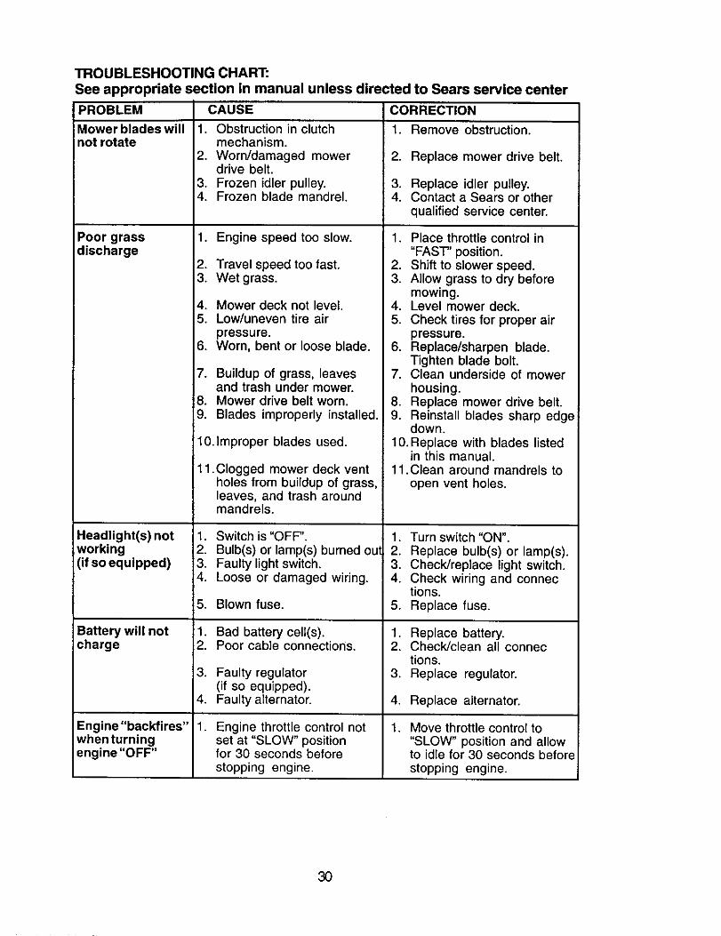
TROUBLESHOOTING CHART:See appropriate section in manual unless directed to Sears service centerPROBLEM
Mower blades willnot rotate
Poor grassdischarge
4.5.
6.
7.
Je.9.
Headlight(s) not 1.working 2.(if so equipped) 3.
4.
5.
Battery will not :1.charge 2.
3.
4.
Engine"backfires" 1.when turningengine "OFF"
CAUSE
1. Obstruction in clutchmechanism.
2. Worn/damaged mowerdrive belt.
3. Frozen idler pulley.4. Frozen blade mandrel.
1. Engine speed too slow.
2. Travel speed too fast.3. Wet grass.
Mower deck not level.Low/uneven tire air
pressure.Worn, bent or loose blade.
Buildup of grass, leavesand trash under mower.Mower drive belt worn.Blades improperly installed.
10.Improper blades used.
11 .Clogged mower deck ventholes from buildup of grass,leaves, and trash aroundmandrels.
Switch is "OFF".
Bulb(s) or lamp(s) burned outFaulty light switch.Loose or damaged wiring.
Blown fuse.
Bad battery celt(s).Poor cable connections.
Faulty regulator(if so equipped).Faulty alternator.
Engine throttle control notset at "SLOW" positionfor 30 seconds beforestopping engine.
CORRECTION
1. Remove obstruction.
2. Replace mower drive belt.
3. Replace idler pulley.4. Contact a Sears or other
qualified service center.
1. Place throttle control in"FAST" position.
2. Shift to slower speed.3. Allow grass to dry before
mowing.4. Level mower deck.5. Check tires for proper air
2. Replace bulb(s) or lamp(s).3. Check/replace light switch.4. Check wiring and connec
tions.5. Replace fuse.
1. Replace battery.2. Check/clean all connec
tions.3. Replace regulator.
4. Replace alternator.
. Move throttle control to"SLOW" position and allowto idle for 30 seconds beforestopping engine.
30
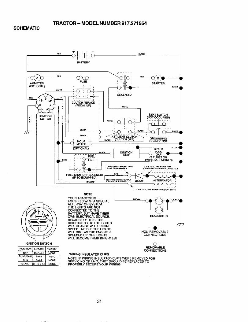
TRACTOR - MODEL NUMBER 917.271554SCHEMATIC
M
BATTERY
AMMETER FUSE
(OPTIONAL) :_ -,
CLUTCH / BRAKE
(PEDAL UP)
IGNITIONSWITCH
j
SOLENOID
WHITE
SEAT SWITCH.... , (NOT OCCUPIED)
WHITE I
q
8tJ_.K J
H GROUNDINGi_ CONNECTOR
(OPTIONAL) _ SPARK 9_
- • \ UNIT ,.._r-I , _UEL, K __ I _PLUGSON ill, '/._ LINE : ]WIN CYL ENGINES) dliTu :o -Z
F LIENOID _- i- :-n--- -
I (IF SO EQUIPPED) r...... _ ,_ - ,,._-______,,' O_NGE " S_TpiA_c.S"x_EMp_JU'PJ' DIODE i ,
@IGNITION SWITCH
PosmoN CIRCUIT '=MAKE"
OFF M+G+A1 NONERUN/LIGPR B+A1 A2+L
RUN B+A1 NONE
START I+S+A1 NONE
NOTEYOUR TRACTOR ISEQUIPPED WITH A SPECIALALTERNATOR SYSTEM.THE LIGHTS ARE NOTCONNECTED TO THEBATFERY, BUT HAVE THEIROWN ELECTRICAL SOURCE.BECAUSE OF THIS, THEBRIGHTNESS OF THE LIGHTSWILL CHANGE WITH ENGINESPEED. AT IDLE THE LIGHTSWILL DIM. AS THE ENGINE ISSPEEDED UP, THE LIGHTSWILL BECOME THEIR BRIGHTEST.
HEADLIGHTS
NON-REMOVABLECONNECTIONS
REMOVABLECONNECTIONS
WIRING INSULATED CLIPS
NOTE: IF WIRING INSULATED CLIPS WERE REMOVED FORSERVICING OF UNIT, THEY SHOULD BE REPLACED TOPROPERLY SECURE YOUR WIRING,
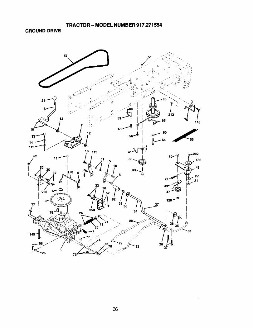
Transaxle (See Breakdown) 50 s'rD523715Peedess206-545C 51 STD541437SpringReturn Brake T/a Zinc 52 STD541431Pulley Transaxle 18/20" tires 53 105710XRing Retainer# 5100-62 55 105709XStrapTorque 30 Degrees 56 17060620Screw 5/16-18 x 3/4 57 130801Bracket Saddle Shift T/a 59 169691Rod ShfSdl LY/YT Str BIk Zinc 61 17120614Pin Cotter 1/8 x 1 Cad 62 8883RWasher Plate Shf 388 Sq Hole 63 175410Washer 15/32 x 3/4 x 16ga 64 71170764Bolt 1/4-28unf Gr8 W/Patch 65 S'rD551143Washer Lock Hvy Helical 1/4 66 154778Bolt Fin Hex 3/8-16 x 1 70 134683Nut Lock Hex W/Ins, 3/8-16 Unc 74 137057Knob Rd 1/2-13 PlstcThds BIk 75 121749XRod Brake BIk Zinc 26 840 76 STD581075Nut Hax Jam 3/8-16 Unc 77 123583XSpring Rod Brake 2 00 Zinc 78 121748XWasher 13/32 x 13/16 x 16 Ga, 79 2226MPin Cotter 1/8 x 3/4 Cad 96 4497HRod Brake Parking LWt 112 19091210Cap Brake Parking 113 127285XBracket Mtg Transaxle 116 72140608Bolt Hax Hd 5/16-18unc x 3/4 120 73900600Shaft Asm Pedal Foot 145 74490540Bearing Nylon BIk 629 ld 150 175456Washer 21/32 x 1 x 16 Ga 151 19133210Pin Roll 3/16 x 1• 170 178394Pulley Idler Composite Ext Hub 202 72110614Bolt Fin Hex 3/8-16 Unc X 3 212 145212Keeper Beltldler 250 17060612Pulley Idler V Groove PlasticBellcrankClutchGm Dr,' StlRetainer BeltStyle Spring
DESCRIPTION
Bolt Hex Hd 3/8-16unc x 1-1/2Nut Crownlock 3/8-16 UNCNut CrownLock 5116-18Link Clutch7 66Spring Return Clutch6 75Screw 3/8-16 x 1-1/4V-Belt Gd DriveKeeper BeltCenterspanScrew 3/8-16 x .875Cover Pedal BIk RoundPulley EngBolt Hex 7116-20 x 4 Gr 5Washer Lock Hvy Hlcl Spr 7/16Keeper Belt EngineGuide Belt Mower Ddve RHSpacer AxleWasher 25/32 x 1 1/4 x 16 GaE-dng#5133-75Key Square 2 0 x 1845/1865Washer 25/32 x 1-518x 16 GaKeyRetainerSpring 1.00Washer 9/32 x 3/4x 10 GaStrapTorqueBolt Rdhd Sq Neck 3/8-16 x 1Nut Lock Fig3/8-16Bolt Hex Flghd 5/16-18 x Gr. 5Spacer RetainerWasher 13/32 x 2 x 10 GaKeeper BeltTransaxleBolt Carr Sh 3/8-16 x 1-3/4 Gr. 5Nut Hex Flange LockScrew 3/8-16 x 3/4
NOTE: All component dimensionsgiven in U. S.inches 1 inch = 25.4 mm
(Used After Date Code 7801041800) 84Piston Assembly (.010" 93Oversize) (Used After DateCode 01041800)Piston Assembly (.020"Oversize) (Used After DateCode 01041800)Piston Assembly (.036"Oversize) (Used After DateCode 01041800)Piston Assembly (Standard)(Used Before Date Code01041900)Piston Assembly (.010"Oversize) (Used BeforeDate Code 01041900)Piston Assembly (.020"Oversize) (Used BeforeDate Code 61041900)Piston Assembly (.030"Oversize) (Used BeforeDate Code 01041900)Ring Set (Standard) (UsedAfter Date Code01041800)Ring Set (.010" Oversize)(Used After Date Code01041800)Ring Set (.020" Oversize)(Used Alter Date CodeO1041800)Ring Set (.030" Oversize)(Used After Date Code01041800)Ring Set-Piston (Standard)(Used Before Date Code010419OO)Ring Set-Piston (.010Oversize) (Used Before DateCode 01041900)Ring Set-Piston (.020Oversize) (Used Before DateCode 01041900)Ring Set-Piston (.030Oversize) (Used Before DateCode 01041900)Lock-Piston PinPin-Piston (Standard)Pin-Piston (.005 Oversize)
Q Included in Carburetor Overhaul Kit, Key.No. 121 and 121A
:1: Included in Carburetor Gasket Set, Key. No.977 and 977A
+ Included in Valve Gasket Set, Key. No. 1095
NOTE: All component dimensions given in U.S.inches 1 inch = 25.4 mm
57
58
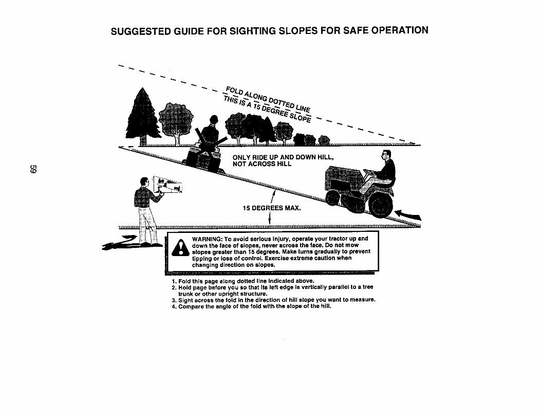
SUGGESTED GUIDE FOR SIGHTING SLOPES FOR SAFE OPERATION
ONLY RIDE UP AND DOWN HILL,NOT ACROSS HILL
15 DEGREES MAX.
_ ARNING: To avoid serious injury, operate your tractor up anddown the face of slopes, never across the face. Do not mowslopes greater than 15 degrees. Make turns gradually to preventtipping or loss of control. Exercise extreme caution whenchanging direction on slopes.
1. Fold this page along dotted line indicated above.2. Hold page before you so that its left edge is vertically parallel to a tree
trunk or other upright structure.3. Sight across the fold in the direction of hill slope you want to measure.4. Compare the angle of the fold with the slope of the hill,
Your Home
For repair - in your home - of all major brand appliances,lawn and garden equipment, or heating and cooling systems,
no matter who made it, no matter who sold it!
For the replacement parts, accessories andowner's manuals that you need to do-it-yourself.
For Sears professional installation of home appliancesand items like garage door openers and water heaters.
1-800-4-MY-HOME _ Anytime, day or night
(1-800-469-4663) (U.S.A, and Canada)www.sears.com www.sears.ca
OurHome
For repair of carry-in products like vacuums, lawn equipment,and electronics, call or go on-line for the nearest
Sears Parts and Repair Center.
1-800-488-1222 Anytime, day or night (U.S.A. only)www.sears.com
To purchase a protection agreement on a product serviced by Sears:
1-800-827,6655 (U.S.A.) 1-800-361-6665 (Canada)
Para pedir servicio de reparaciSna domicilio, y para ordenar piezas:
1-888-SU-HOGAR _v(1-888_784-64217)
Au Canada pour service en franc._ais:1-800-LE-FOYER uc
SM® Registered Trademark / _v Trademark / Service Mark of Sears, Roebuck and Co.
® Marca Registrada/'rM Mama de F&brica / SMMarca de Servicio de Sears, Roebuck and Co.McMarque de commerce / MOMarque deposee de Sears, Roebuck and Co.


![18.5 HP, 42 Mower Electric Start Automatic …Owner's Manual]CRRFTSMRN"I LAWN TRACTOR 18.5 HP, 42" Mower Electric Start Automatic Transmission Model No. 917.275643 This product has](https://static.documents.pub/doc/80x56/5e98a1719bdf70184608de76/185-hp-42-mower-electric-start-automatic-owners-manualcrrftsmrni-lawn.jpg)


