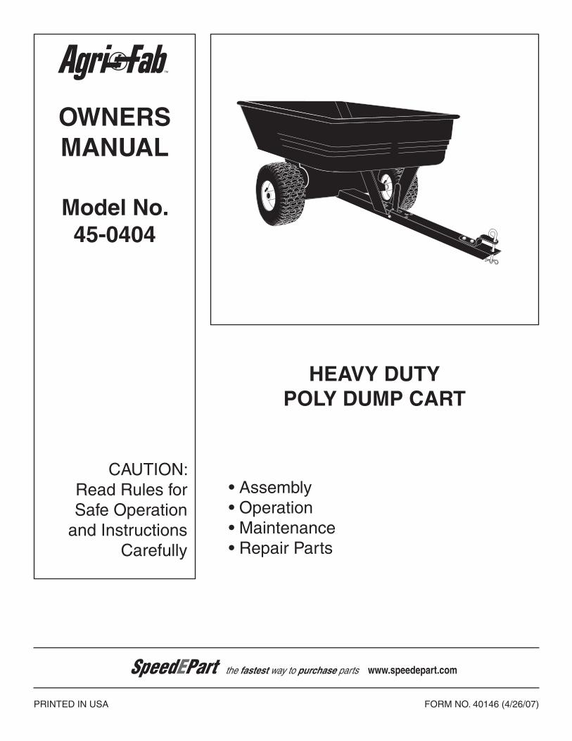
Model No. 45-0404 PRINTED IN USA FORM NO. 40146 (4/26/07) HEAVY DUTY POLY DUMP CART OWNERS MANUAL • Assembly • Operation • Maintenance • Repair Parts CAUTION: Read Rules for Safe Operation and Instructions Carefully the fastest way to purchase parts www.speedepart.com ™
Transcript
Model No.45-0404
PRINTED IN USA FORM NO. 40146 (4/26/07)
HEAVY DUTYPOLY DUMP CART
OwNERsMANUAL
• Assembly• Operation• Maintenance• Repair Parts
CAUTION:Read Rules forSafe Operation
and InstructionsCarefully
the fastest way to purchase parts www.speedepart.com
™
2
sAFETY RULEsRemember, any power equipment can cause injury if operated improperly or if the user does not understand how to operate the equipment. Exercise caution at all times when using power equipment.
CARTON CONTENTs
LOOK FOR THIs sYMBOL TO POINT OUT IMPORTANT sAFETY PRECAUTIONs. IT MEANs — ATTENTION! BECOME ALERT! YOUR sAFETY Is INVOLVED.
1. Poly Tray2. Wheel Support3. Latch Stand Plate4. Latch Stand Bracket
CARTON CONTENTs (Loose Parts)
CAUTION: VEHICLE BRAKING AND sTABILITY MAY BE AFFECTED wITH THE ADDITION OF AN ACCEssORY OR AN ATTACHMENT. BE AwARE OF CHANGING CONDITIONs ON sLOPEs.
Exercise caution at all times when using power equipment. Read this owners manual before attempting to assemble or operate the cart. Read the vehicle owners manual and know how to operate your vehicle before using the cart attachment. Do not at any time carry passengers in this cart. It has not been designed to carry passengers. Never allow children to operate the vehicle or the cart attachment. Do not allow adults to operate the vehicle or cart attachment without proper instructions. Alwaysbeginwiththetransmissioninfirst(low)andgraduallyincreasespeedasconditionspermit. Tow the cart at reduced speed over rough terrain and hillsides or near creeks and ditches to prevent tipping over and
loss of control. Do not drive too close to a creek or ditch. Vehiclebrakingandstabilitymaybeaffectedwiththeattachmentofthiscart.Donotfillcarttomaximumweightcapacity
without checking the capability of the towing vehicle to safely pull and stop with the cart attached. Before operating vehicle on any grade (hill) refer to the safety rules in the vehicle owner's manual concerning safe opera-
tion on slopes. Refer also to the slope guide on page 11 of this manual. stay off steep slopes! Do not tow this cart on highways or on public thoroughfares. Maximum towing speed is 10 m.p.h. Follow maintenance and lubrication instructions as outlined in this manual.
1. Remove the hardware pack and all loose parts from the carton. Be sure the carton is empty before discarding.
2. Lay out and identify all the parts and hardware as shown on pages 2 and 3.
3. Place the latch lock lever through the slot in the draw bartongueasshowninfigure1.Assemblethe5/16"x4" hex bolt through the tongue, the lever and two 5/16" (SEMS) nuts (one on each side of the lever). Assemble a 5/16" nylock nut onto the end of the bolt and tighten so that the bolt can still rotate freely. Tighten the two 5/16" (SEMS) nuts against the sides of the latch lock leversothattheleveriscenteredintheslot.Seefigure1.
FIGURE 3
FIGURE 1
5. Assemble the hitch bracket to the drawbar tongue using two 3/8" x 1" hex bolts and 3/8" nylock nuts. Tighten. Seefigure3.
6. Assemble the hitch pin to the tongue and hitch bracket andsecureitwiththehaircotterpin.Seefigure3.
5/16" x 4"HEX BOLT
DRAWBAR TONGUE
LATCHLOCKLEVER
5/16" (SEMS) NUTS
5/16"NYLOCKNUT
4. Hook the short end of the spring into the hole in the latch lock lever. Use the spring puller tool to hook the long end of the spring into the square hole in the tongue. Thespringpullertoolcanbestoredwhenfinished.Seefigure2.
LONG ENDOF SPRING
LATCH LOCK LEVER
SPRINGPULLER TOOL
3/8" x 1"HEX BOLT
3/8" NYLOCKNUT
HITCHBRACKET
HAIRCOTTERPIN
HITCH PIN
5
FIGURE 5
9. Assemble the latch stand plate and the latch stand bracket to the bottom of the poly tray using four 1/4" x 3/4" hex bolts, 1/4" flat washers and 1/4" nylocknuts. The aligning tab on the bottom of the latch stand bracket must be towards the rear of the cart. Tighten. Seefigure6.
FIGURE 7
7. Assemble the axle and drawbar tongue to the wheel support, with the open side of tongue facing away from the wheel support. Fasten the axle to the wheel support using four 1/4" x 1-3/4" hex bolts and 1/4" nylock nuts. Tighten.Seefigure4.
FIGURE 6
10. Place the poly tray down onto the wheel support, positioning it so that the latch stand bracket snaps under the latch lock lever. Fasten the tray to the wheel support using eight 5/16" x 3/4" truss head bolts and 5/16"nylocknutsasshowninfigure7.Tighten.
FIGURE 4
5/16" NYLOCK NUT
5/16" x 3/4"TRUSS HEADBOLT
LATCH LOCKLEVER
COTTER PIN
WHEEL
1" FLATWASHER
1" FLATWASHER
AXLE
8. Assemblea1"flatwasher,awheel(valvestemfacingout)andanother1"flatwasherontotheaxleasshowninfigure5.Insertacotterpinthroughtheaxle,spreadingthe ends. Repeat on other end of axle.
AXLE
WHEELSUPPORT
DRAW BARTONGUE
1/4" x 1-3/4"HEX BOLT
1/4" NYLOCK NUT
1/4" FLATWASHER
1/4" NYLOCK NUT
1/4" x 3/4"HEX BOLT
LATCH STANDBRACKET
LATCHSTAND PLATE
TAB
6
OPERATION
CAUTION: VEHICLE BRAKING AND sTABILITY MAY BE AFFECTED wITH THE ADDITION OF AN ACCEssORY OR AN ATTACHMENT. BE AwARE OF CHANGING CONDITIONs ON sLOPEs.
1. Refer to the vehicle owners manual for instructions on safe operation on slopes.
2. Use the slope guide provided on page 11 of this manual to determine whether slope angle is too steep for safe operation.
3. For best handling and traction, distribute the weight of the load evenly in the cart.
4. Always test to make sure your vehicle has adequate towing and braking capabilities whenever hauling a substantial amount of weight in your cart. Use extra caution when operating on slopes.
NOTE
DO NOT EXCEED wEIGHT CAPACITY OF CART(Seethespecificationsonthispage.)One cubic foot of dirt weighs approximately 80 lbs.
Tires: 15" x 6" PneumaticAxle: 1" Dia. SteelCapacity: Up to 750 Lbs. Max.
CART sPECIFICATIONs
CAUTION: TO AVOID POssIBLE INJURY, BEFORE RELEAsING THE LATCH BE sURE THAT NO ONE Is NEAR THE CART.
5. To dump material from the cart, release the spring latch on the tongue by pulling the latch lock lever forward, away from the cart. The cart bed will then tilt backwards to empty its contents. After emptying, pull the front of the bed down toward the cart tongue until the latch snaps into place.
6. The maximum towing speed for this cart is 10 m.p.h.
MAINTENANCE
1. At the beginning of each season, using a light machine oil, lubricate the latch, the latch pivot bolt, and the area of the axle where the draw bar tongue pivots .
2. At the beginning of each season, grease or oil the wheel bearings.
3. Check periodically for loose bolts.
4. Keeptiresfilled.Donotexceedmaximumtirepressureprinted on tires.
7
NOTEs
8
REPAIR PARTs FOR HEAVY DUTY POLY DUMP CART MODEL 45-0404
the fastest way to purchase parts www.speedepart.com
REPAIR PARTs FOR HEAVY DUTY POLY DUMP CART MODEL 45-0404
10
sLOPE GUIDE(Keep this sheet in a safe place for future reference.)
Use this guide to determine if a slope is safe for the operation of your tractor and cart. Refer also to the instructions in your vehicle owners manual.
CA
UT
ION
: DO
NO
T O
PE
RA
TE
YOU
R T
RA
CTO
R A
ND
CA
RT
ON
A s
LO
PE
IN
EX
CE
ss
OF
10 DE
GR
EE
s. B
E s
UR
E O
F Y
OU
R T
RA
CTO
R's
TOw
ING
A
ND
BR
AK
ING
CA
PAB
ILIT
IEs
BE
FO
RE
OP
ER
AT
ING
ON
A s
LO
PE
. A
VO
ID A
NY
sU
DD
EN
TU
RN
s O
R M
AN
EU
VE
Rs
wH
ILE
ON
A s
LO
PE
.
A P
OW
ER
PO
LE
A C
OR
NE
R O
F A
BU
ILD
ING
OR
A F
EN
CE
PO
ST
FOLD
ALO
NG
DO
TTED
LINE
, RE
PR
ES
EN
TING
A 10 D
EG
RE
E S
LOP
E
SIG
HT
AN
D H
OL
D T
HIS
LE
VE
L W
ITH
A V
ER
TIC
AL
TR
EE
12
the fastest way to purchase parts www.speedepart.com
This document (or manual) is protected under the U.S. Copyright Laws and the copyright laws of foreign countries, pursuant to the Universal Copyright Convention and the Berne convention. No part of this document may be reproduced or transmitted in any form or by an means, electronic or mechanical, including photocopying or recording, or by any information storage or retrieval system, without the express written permission of Agri-Fab, Inc. Unauthorized uses and/or reproductions of this manual will subject such unauthorized user to civil and criminal penalties as provided by the United States Copyright Laws.