DPX16: Instructions for Basic Operation and Installation Page 2
Table of ContentsIntroduction ........................................................................................................................................................................................ 3Operational Features Description....................................................................................................................................................... 3
Live Camera Displays.................................................................................................................................................................. 3Activity Detection and Alarming ................................................................................................................................................... 3Multiplexer Recording/Playback................................................................................................................................................... 3DigiLock� and Playback.............................................................................................................................................................. 4VCR Bypass ..................................................................................................................... ........................................................... 4Call Monitor ................................................................................................................... .............................................................. 4Advanced Alarm System with Alarm Scheduling ......................................................................................................................... 4Alarm Log and Printing ................................................................................................................................................................ 4Variable Zoom ............................................................................................................................................................................. 4
VCR Bypass Function Operation ................................................................................................................................................. 8Call Monitor Operation................................................................................................................................................................. 8Remote Control Operation........................................................................................................................................................... 8Activity Detection Operation......................................................................................................................................................... 8
Set Up Menus .................................................................................................................................................................................... 9Main Menu ............................................................................................................................................................................ 9
Time/Date Setting ........................................................................................................................................................... 9Time & Date Display Options ........................................................................................................................................ 10VCR Set Up .................................................................................................................................................................. 10
VCR Selection.......................................................................................................................................................... 10Advanced Function Menus............................................................................................................................................................... 11
Camera Set Up ................................................................................................................................................................... 11Camera Label Changing ............................................................................................................................................... 11CUSTOMPLEXING� (Camera Recording Priority)........................................................................................................ 11Camera Monitor Disable ............................................................................................................................................... 12Activity Detection Set Up............................................................................................................................................... 12
Display Sequence Set Up.................................................................................................................................................... 13Dwell Adjustment .......................................................................................................................................................... 13Display Sequencing Format .......................................................................................................................................... 13Sequencing Format Screens......................................................................................................................................... 13
Alarm Set Up....................................................................................................................................................................... 15Alarm Enable Type ....................................................................................................................................................... 15Video Loss Alarms........................................................................................................................................................ 15Alarm Scheduling.......................................................................................................................................................... 15
Set Alarm Enable Schedule ..................................................................................................................................... 16Enable Scheduled Alarms ........................................................................................................................................ 16
Alarm Control Options................................................................................................................................................... 17Alarm Dwell Adjustment ........................................................................................................................................... 17Alarm Activation Type .............................................................................................................................................. 18
Security Set Up............................................................................................................................................................. 19Advanced VCR Options....................................................................................................................................................... 20
Camera Switch Input..................................................................................................................................................... 20Hand Held IR Remote Control.......................................................................................................................................................... 21
Programming Your ATV DPX16 Remote Control....................................................................................................................... 21What to do if Your VCR is not on the Supported List........................................................................................................................ 22Programming a Custom Delay Table (Advanced Option) ................................................................................................................. 22
What is the “Delay Table”? ........................................................................................................................................................ 22Determining Delay Values................................................................................................................................................................ 22
Edit Delay Table ........................................................................................................................................................................ 23How do I verify the correct “Values”? ......................................................................................................................................... 23
Alarm Interconnection on the DPX16 ............................................................................................................................................... 24RS-232 Remote Control Interface .................................................................................................................................................... 26Supported VCRs.............................................................................................................................................................................. 27Specifications................................................................................................................................................................................... 28Warranty Information ....................................................................................................................................................................... 29
YEAR 2000 CONFORMANCE................................................................................................................................................... 29LIMITATION OF WARRANTY ................................................................................................................................................... 29
DPX16: Instructions for Basic Operation and Installation Page 3
INTRODUCTION
Thank you for purchasing Advanced Technology Video’s DPX16 sixteen camera Color Duplex Multiplexer.This instruction manual describes the powerful features of this product for basic and advanced operation.It also covers the installation steps that will allow quick and easy integration into your security system.
The following section provides an overview of the operational features of the DPX16. If you are familiarwith the DPX16, you should proceed to the “Getting Started” section on the following page for step by stepinstallation instructions.
OPERATIONAL FEATURES DESCRIPTION
Live Camera Displays
The DPX16 will initially be in the live camera display mode whenever power is applied to the unit. Livecameras can be displayed in 4x4, 3x3, quad, PIP, dual PIP, split screen, squish screen, or full frameformats. In addition, any display may be frozen using a front panel button, the IR remote control, orexternal signal input. In any of these display modes, the unit can be programmed to sequence one ormore cameras with a programmable dwell time. All live camera displays, with the exception of 4x4 and3x3 formats, are in real time (30 frames/60 fields per second NTSC, or 25 frames/50 fields per secondPAL).
Activity Detection and Alarming
The DPX16’s advanced video processing capability provides an activity detection function for eachcamera input. Activity Detection, for each camera, can be programmed in 240 regions (cells) and may beselectively enabled to provide an “alarm” condition for the multiplexer. See “Activity Detection Operation”on page 8 for further information regarding the configuration and use of this feature.
Multiplexer Recording/Playback
The DPX16 records each camera individually onto a single video frame of the VCR tape at a ratecompatible with the VCR recording speed (record hours mode). Proper VCR playback operation requiresthat the DPX16 be set up to multiplex at the rate which is compatible with your VCR recording speed (seepage 10). During multiplexing, a single frame from each camera is alternately output to the VCR with thefactory default set so that each live camera is given an equal number of frames on the tape. Dead orunconnected camera inputs will not be recorded. In order to optimize recording for your security situation,the frequency with which individual camera inputs are sampled for multiplexing may be optionallyconfigured using either Activity Detection or the Customplexing� camera priority function. When ActivityDetection is enabled, the multiplexing rate of a camera is automatically increased when activity is detectedin the camera’s image. Cameras with activity will be sampled more often than cameras with little or noactivity. When Activity Detection is disabled, the Customplexing� feature is automatically enabled and upto four levels of multiplexing priority can be set for each camera using the “Recording Priority” menu (moreframes are given to high priority and less frames to low priority). Alarm events will automatically raise therecording priority of the alarming camera to the highest level during the alarm condition. While multiplexrecording is active, the live display mode can be set to any mode (4x4, 3x3, quad, PIP, Dual PIP or fullscreen, etc.) without affecting the multiplex recording function.
In VCR playback mode, cameras can be displayed in 4x4, 3x3, quad, PIP, dual PIP, split screen, squishscreen, or full frame formats. In addition, any display may be frozen. VCR playback incorporates digitaldecoding of the camera number from the tape so that screen images on the monitor may be updated atthe rate that images appear on the tape. The default refresh rate of the playback monitor is the playbackrate divided by the number of cameras being multiplexed. This will change when alarmed cameras ordead cameras are present or camera priorities have been changed.
��������������� �������������
DPX16: Instructions for Basic Operation and Installation Page 4
DigiLock �� and Playback
In VCR playback mode, digital information is used to compensate for the poor vertical synchronizationsignals frequently encountered with time lapse VCRs.
The DPX16 DigiLock� decoding reconstructs the timing such that successfully decoded frames aredisplayed with minimal “jumping”, “tearing” or other side-effects of poor synchronization.
VCR Bypass
Many VCRs have on-screen programming menus that require a monitor for programming the VCR. TheDPX16 includes a “VCR Bypass” feature which facilitates VCR programming by allowing theDPX16 VCR input (VCR’s video output) to be routed directly to the display monitor. The “VCR Bypass”mode can also be used to directly view the VCR’s output for adjusting tracking or verifying proper VCRconnections to the DPX16.
Call Monitor
An additional, separate monitor function is provided to allow simultaneous viewing of full screen cameradisplays and full screen alarm or sequenced cameras. The Call Monitor output is always a full screen callup of any input camera. The camera to be viewed can be selected manually or may be selectedautomatically as the alarming camera. In addition, this output can be set to sequence through allcameras. The default mode is sequencing. See “Call Monitor Operation” on page 8 for instructions on theoperation of the Call Monitor.
Advanced Alarm System with Alarm Scheduling
The DPX16 contains the most advanced and flexible Alarm System available in a video multiplexer. TheDPX16 Advanced Alarm System supports several programmable alarm types including external input,Activity Alarms, and Video Loss Alarms. In addition, the DPX16 alarm system can be enabled anddisabled through a 7-day Alarm Schedule and/or a user programmable external Master Enable signal.
The DPX16 has sixteen, alarm “channels” associated with the sixteen camera inputs. Each alarm“channel” includes a programmable external input, video Activity Alarm, and Video Loss Alarm. Externalalarm inputs are individually selectable for contact closure or opening as well as logic levels (+5V, 0V).Each alarm “channel” may also be individually selected for enable/disable through the DPX16 AlarmSchedule. The Alarm Schedule is a 7-day timer schedule with a single ON and OFF time associated witheach day of the week. The DPX16 also has an external input signal that can be selected between pictureFreeze and Alarm Master Enable. The Alarm Master Enable signal can be used in conjunction with yourburglar alarm control panel so that the alarm control panel can enable or disable the DPX16 alarmsystem. See page 15 for further information on Alarm Scheduling and DPX16 alarm features.
Alarm Log and Printing
The DPX16 has an internal Alarm Log that provides storage for up to 100 alarm events. In addition, itstext can be transmitted to the serial port for printing or storage on a host computer. The Alarm Log is a“circular” storage buffer so that the most recent alarm events are always stored. In addition to the AlarmLog, alarm event text can also be sent directly to the serial port, when an event occurs, for immediateprinting or external processing. Alarm events, which may be printed and stored in the Alarm Log, includeany enabled External Alarms, Activity Alarms, or Video Loss Alarms. See “Alarm Set Up” on page 15 forinstructions on the use of the DPX16 alarm log and printing features.
Variable Zoom
The DPX16 has an easy to use variable magnification and adjustable position Zoom capability. The frontpanel buttons marked with arrow symbols are used to adjust the position of the Zoom window and theZoom button and VCR button are used to “zoom in” and “zoom out” respectively. Zoom is available in livecamera and VCR playback modes.
��������������� �������������
DPX16: Instructions for Basic Operation and Installation Page 5
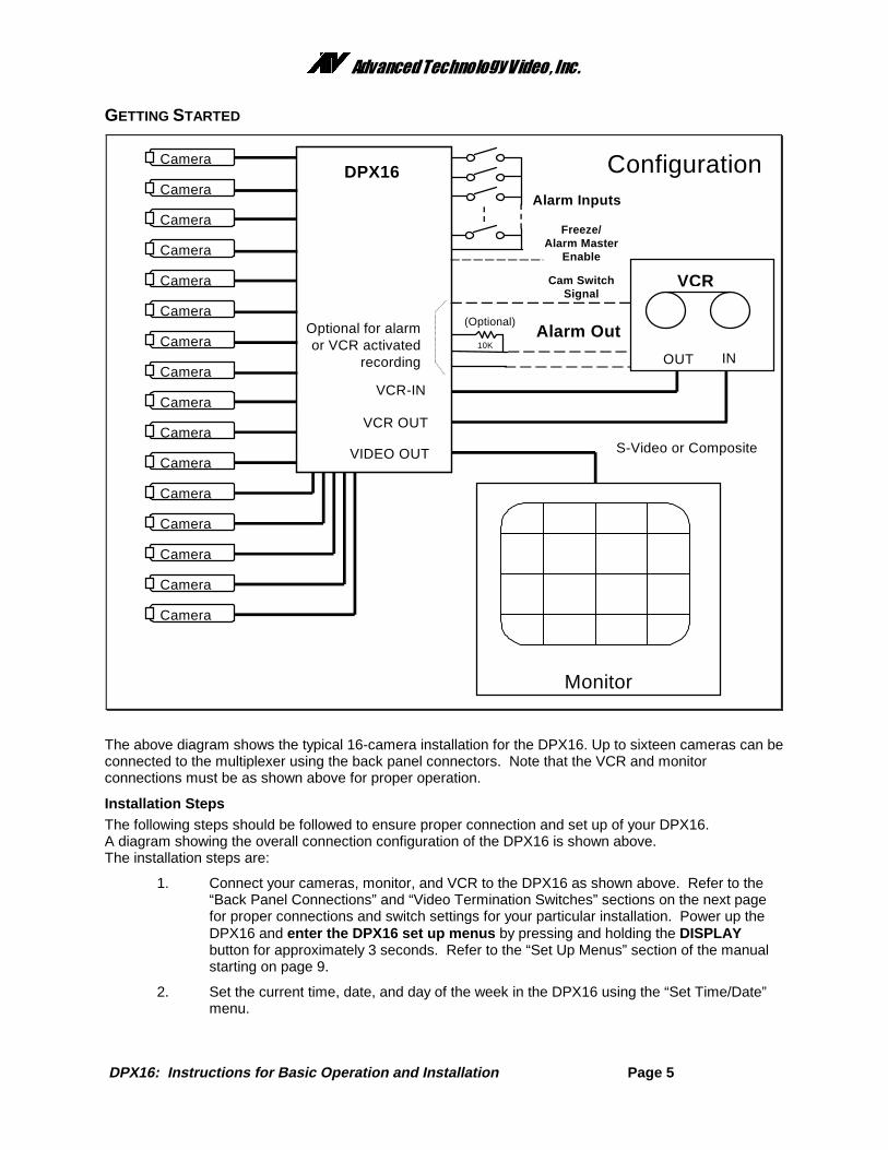
GETTING STARTED
The above diagram shows the typical 16-camera installation for the DPX16. Up to sixteen cameras can beconnected to the multiplexer using the back panel connectors. Note that the VCR and monitorconnections must be as shown above for proper operation.
Installation StepsThe following steps should be followed to ensure proper connection and set up of your DPX16.A diagram showing the overall connection configuration of the DPX16 is shown above.The installation steps are:
1. Connect your cameras, monitor, and VCR to the DPX16 as shown above. Refer to the“Back Panel Connections” and “Video Termination Switches” sections on the next pagefor proper connections and switch settings for your particular installation. Power up theDPX16 and enter the DPX16 set up menus by pressing and holding the DISPLAYbutton for approximately 3 seconds. Refer to the “Set Up Menus” section of the manualstarting on page 9.
2. Set the current time, date, and day of the week in the DPX16 using the “Set Time/Date”menu.
Alarm Inputs
Camera
Camera
Camera
10K
(Optional)Alarm Out
DPX16 Configuration
VIDEO OUT
VCR-IN
Camera
Camera
Camera
Camera
Camera
VCR OUT
VCR
OUT IN
Optional for alarmor VCR activated
recording
Monitor
Cam SwitchSignal
Camera
Camera
Camera
Camera
Camera
Camera
Camera
Camera
S-Video or Composite
Freeze/Alarm Master
Enable
��������������� �������������
DPX16: Instructions for Basic Operation and Installation Page 6
3. Determine the record speed (record hours format) you will use with your VCR and set upthe DPX16 to work with your VCR using the “VCR Set up” and “VCR Selection” menus(see page 10).
4. Exit the DPX16 menus by pressing the DISPLAY button to exit each menu and finally themenu system.
5. If your VCR has internal “on-screen” menus for its set up, use the “VCR Bypass” featureof the DPX16 (see the “VCR Bypass Operation” description on page 8) to view the VCR’s“on-screen” menus on the display monitor.
6. At this point, the basic configuration of your DPX16 is complete. You may now proceed toset more advanced functions as required for your installation (alarms, camera labels,multiplexing options, etc.). Refer to the “Advanced Function Menus” starting on page 11for detailed information for the feature(s) you require.
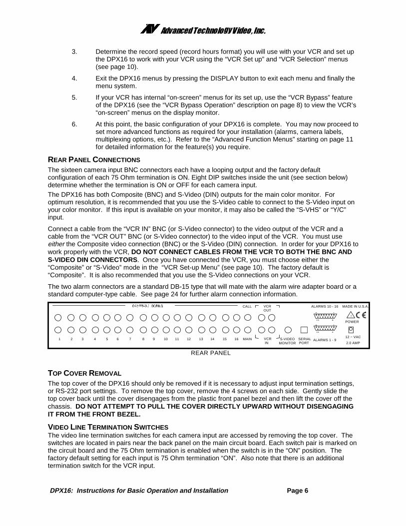
REAR PANEL CONNECTIONS
The sixteen camera input BNC connectors each have a looping output and the factory defaultconfiguration of each 75 Ohm termination is ON. Eight DIP switches inside the unit (see section below)determine whether the termination is ON or OFF for each camera input.
The DPX16 has both Composite (BNC) and S-Video (DIN) outputs for the main color monitor. Foroptimum resolution, it is recommended that you use the S-Video cable to connect to the S-Video input onyour color monitor. If this input is available on your monitor, it may also be called the “S-VHS” or “Y/C”input.
Connect a cable from the “VCR IN” BNC (or S-Video connector) to the video output of the VCR and acable from the “VCR OUT” BNC (or S-Video connector) to the video input of the VCR. You must useeither the Composite video connection (BNC) or the S-Video (DIN) connection. In order for your DPX16 towork properly with the VCR, DO NOT CONNECT CABLES FROM THE VCR TO BOTH THE BNC ANDS-VIDEO DIN CONNECTORS. Once you have connected the VCR, you must choose either the“Composite” or “S-Video” mode in the “VCR Set-up Menu” (see page 10). The factory default is“Composite”. It is also recommended that you use the S-Video connections on your VCR.
The two alarm connectors are a standard DB-15 type that will mate with the alarm wire adapter board or astandard computer-type cable. See page 24 for further alarm connection information.
18
915
REAR PANEL
������� � �� �
16151413121110987654321 MAIN
VCROUT
VCRIN
S-VIDEOMONITOR
SERIALPORT
ALARMS 10 - 16
ALARMS 1 - 9
POWER
12 ~ VAC
2.0 AMP
MADE IN U.S.A.
18
915
CALL
!
TOP COVER REMOVAL
The top cover of the DPX16 should only be removed if it is necessary to adjust input termination settings,or RS-232 port settings. To remove the top cover, remove the 4 screws on each side. Gently slide thetop cover back until the cover disengages from the plastic front panel bezel and then lift the cover off thechassis. DO NOT ATTEMPT TO PULL THE COVER DIRECTLY UPWARD WITHOUT DISENGAGINGIT FROM THE FRONT BEZEL.
VIDEO LINE TERMINATION SWITCHESThe video line termination switches for each camera input are accessed by removing the top cover. Theswitches are located in pairs near the back panel on the main circuit board. Each switch pair is marked onthe circuit board and the 75 Ohm termination is enabled when the switch is in the “ON” position. Thefactory default setting for each input is 75 Ohm termination “ON”. Also note that there is an additionaltermination switch for the VCR input.
��������������� �������������
DPX16: Instructions for Basic Operation and Installation Page 7
OPERATION
� � � � � � � � � �� �� �� �� �� ��
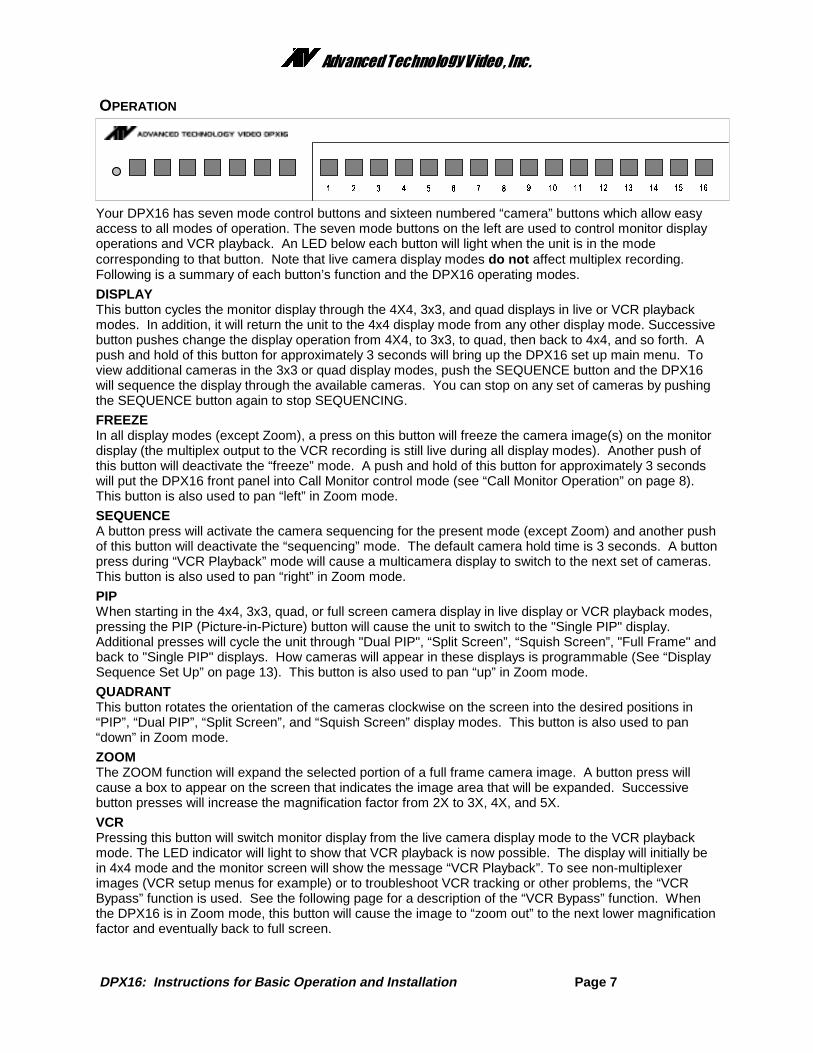
Your DPX16 has seven mode control buttons and sixteen numbered “camera” buttons which allow easyaccess to all modes of operation. The seven mode buttons on the left are used to control monitor displayoperations and VCR playback. An LED below each button will light when the unit is in the modecorresponding to that button. Note that live camera display modes do not affect multiplex recording.Following is a summary of each button’s function and the DPX16 operating modes.
DISPLAYThis button cycles the monitor display through the 4X4, 3x3, and quad displays in live or VCR playbackmodes. In addition, it will return the unit to the 4x4 display mode from any other display mode. Successivebutton pushes change the display operation from 4X4, to 3x3, to quad, then back to 4x4, and so forth. Apush and hold of this button for approximately 3 seconds will bring up the DPX16 set up main menu. Toview additional cameras in the 3x3 or quad display modes, push the SEQUENCE button and the DPX16will sequence the display through the available cameras. You can stop on any set of cameras by pushingthe SEQUENCE button again to stop SEQUENCING.
FREEZEIn all display modes (except Zoom), a press on this button will freeze the camera image(s) on the monitordisplay (the multiplex output to the VCR recording is still live during all display modes). Another push ofthis button will deactivate the “freeze” mode. A push and hold of this button for approximately 3 secondswill put the DPX16 front panel into Call Monitor control mode (see “Call Monitor Operation” on page 8).This button is also used to pan “left” in Zoom mode.
SEQUENCEA button press will activate the camera sequencing for the present mode (except Zoom) and another pushof this button will deactivate the “sequencing” mode. The default camera hold time is 3 seconds. A buttonpress during “VCR Playback” mode will cause a multicamera display to switch to the next set of cameras.This button is also used to pan “right” in Zoom mode.
PIPWhen starting in the 4x4, 3x3, quad, or full screen camera display in live display or VCR playback modes,pressing the PIP (Picture-in-Picture) button will cause the unit to switch to the "Single PIP" display.Additional presses will cycle the unit through "Dual PIP", “Split Screen”, “Squish Screen”, "Full Frame" andback to "Single PIP" displays. How cameras will appear in these displays is programmable (See “DisplaySequence Set Up” on page 13). This button is also used to pan “up” in Zoom mode.
QUADRANTThis button rotates the orientation of the cameras clockwise on the screen into the desired positions in“PIP”, “Dual PIP”, “Split Screen”, and “Squish Screen” display modes. This button is also used to pan“down” in Zoom mode.
ZOOMThe ZOOM function will expand the selected portion of a full frame camera image. A button press willcause a box to appear on the screen that indicates the image area that will be expanded. Successivebutton presses will increase the magnification factor from 2X to 3X, 4X, and 5X.
VCRPressing this button will switch monitor display from the live camera display mode to the VCR playbackmode. The LED indicator will light to show that VCR playback is now possible. The display will initially bein 4x4 mode and the monitor screen will show the message “VCR Playback”. To see non-multiplexerimages (VCR setup menus for example) or to troubleshoot VCR tracking or other problems, the “VCRBypass” function is used. See the following page for a description of the “VCR Bypass” function. Whenthe DPX16 is in Zoom mode, this button will cause the image to “zoom out” to the next lower magnificationfactor and eventually back to full screen.
��������������� �������������
DPX16: Instructions for Basic Operation and Installation Page 8
VCR Bypass Function OperationAn approximately 3 second long press of the VCR button activates the “VCR Bypass” function and theVCR LED will flash while the unit is in “VCR Bypass” mode. While in this mode, the DPX16 will pass theVCR output directly to the main display monitor. A single push of the VCR button will return the unit tonormal VCR playback mode and/or back to live display mode. The VCR output is also available on theCall Monitor.
CAMERA Buttons (1 Through 16)The individual camera buttons 1 through 16 are used to select which camera is to be used for displaypurposes during live display or VCR playback modes. In addition, Camera buttons 1 through 16 are usedin the DPX16 set up menus.
Call Monitor OperationThe Call Monitor output is always active and is independent of the main display monitor. The camera thatis being viewed on the Call Monitor may be selected by pressing the FREEZE button (except while inZoom mode) and holding it for approximately 3 seconds. When the DPX16 is in “Call Monitor mode”, theFREEZE LED will flash on and off. At this time, any camera that is “alive” may be selected by pressing theCAMERA button. In addition, the Call Monitor output may be set to sequence through “alive” cameras bypressing the SEQUENCE button. The SEQUENCE LED will light and the Call Monitor output willsequence through all “alive” cameras. The Call Monitor output defaults to “sequencing” mode and willautomatically display any “alarming” camera. It is also possible to view the VCR IN and VCR OUT signalsusing the Call Monitor. When in “Call Monitor” mode, a single press of the VCR button will display VCR INon the Call Monitor. A second press of the VCR button will display VCR OUT. Successive presses of theVCR button will toggle the Call Monitor display between VCR IN and VCR OUT.
Remote Control OperationThe IR remote control provided with your DPX16 has a limited set of buttons and operation with theremote control is slightly different than the DPX16 front panel. The remote control has a single CAMERAbutton for selecting cameras and successive button presses will rotate through the available cameras.Sequencing is initiated by pressing and holding the remote control’s FREEZE button for approximately 3seconds. Pressing and holding the remote control’s “PIP” button for approximately 3 seconds accessesthe Call Monitor mode. Pressing and holding the “QUADRANT” button for approximately 3 secondsaccesses the ZOOM function. Note that menus are not available through the remote control and theremote control must be programmed any time the batteries are removed. See “Programming YourATV DPX16 Remote Control” on page 21.
Activity Detection OperationThe Activity Detection feature of the DPX16 can be used to control camera multiplexing and optionallygenerate alarm conditions. Activity Detection, when enabled, will be active on every “live” camera inputand can be individually customized for each camera. Activity Detection control and set up is found in the“Camera Set Up” menu on page 11.
There are two programmable settings possible for each camera under the “Activity Detection” menu onpage 12; “Activity Threshold”, and “Activity Zones”. The “Activity Threshold” is a relative sensitivity levelfor activity within the entire camera image. Higher numbers represent a higher threshold value andtherefore a lower sensitivity to activity. In order to allow areas of an image to be enabled or disabled foractivity detection, each camera’s image is divided into 240 regions (15 columns by 16 rows). The“Enable/Disable Activity Zones” option in the “Activity Detection” menu is used for programming of theseregions for each camera. To facilitate the identification of areas of an image with activity, an “autodetection” mode for “Activity Zones” and “Activity Threshold” programming is provided. The on-screeninstructions allow efficient configuration of each camera’s Activity Detection settings.
Note that camera multiplexing priority is determined by either Activity Detection orCustomplexing ��, but not both simultaneously . When Activity Detection is enabled, Customplexing�camera priority settings are not used to determine camera multiplexing priority. Similarly, when ActivityDetection is disabled, Customplexing� camera priority settings, and not Activity Detection, are used todetermine multiplexing priority.
��������������� �������������
DPX16: Instructions for Basic Operation and Installation Page 9
SET UP MENUS
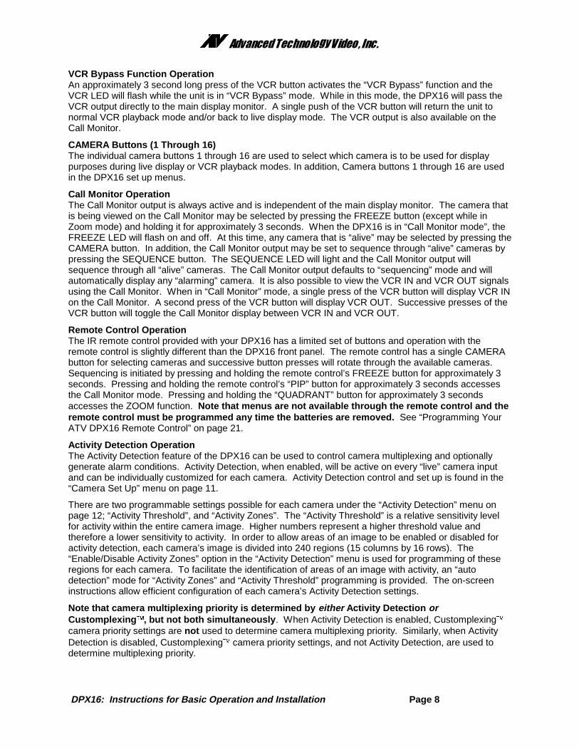
The DPX16 set up is accomplished through its on-screen menus. To enter the menu system, push andhold the DISPLAY button for approximately 3 seconds. The display will then show the top level menu.Selection of any menu item is done with the camera select keys on the front panel. Selecting DISPLAYwill exit the present menu level. Note that since DPX16 operating modes are affected by menu settings,the DPX16 will not operate as desired until the menu system is exited , returning the DPX16 to itsnormal operating mode.
Main MenuSelecting:
1. Enters “Set Time/Date” menu to program the internalclock and select time and date display options.
2. Enters “VCR Set Up” menu to select VCR type andrecording format (Hours).
3. Enters “Camera Set Up” menu to program cameralabels and set recording priorities.
4. Enters display “Sequence Set Up” menu to set thesequence cameras will be displayed in.
5. Enters “Alarm Set Up” menu to enable/disable alarmsand program alarm action.
6. Enters the “Other Options” menu where you canselect remote control code, program a security code for locking out the menus and the frontpanel buttons, change text color and background, or reset unit to factory defaults.
7. Selects the language used for DPX16 menus and messages.
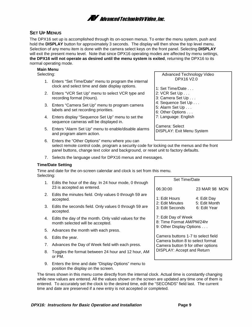
Time/Date SettingTime and date for the on-screen calendar and clock is set from this menu.Selecting:
1. Edits the hour of the day. In 24 hour mode, 0 through23 is accepted as entered.
2. Edits the minutes field. Only values 0 through 59 areaccepted.
3. Edits the seconds field. Only values 0 through 59 areaccepted.
4. Edits the day of the month. Only valid values for themonth selected will be accepted.
5. Advances the month with each press.
6. Edits the year.
7. Advances the Day of Week field with each press.
8. Toggles the format between 24 hour and 12 hour, AMor PM.
9. Enters the time and date “Display Options” menu toposition the display on the screen.
The times shown in this menu come directly from the internal clock. Actual time is constantly changingwhile new values are entered. All the values shown on the screen are updated any time one of them isentered. To accurately set the clock to the desired time, edit the “SECONDS” field last. The currenttime and date are preserved if a new entry is not accepted or completed.
Advanced Technology Video DPX16 V2.0
1: Set Time/Date . . . 2: VCR Set Up . . . 3: Camera Set Up . . . 4: Sequence Set Up . . . 5: Alarm Set Up . . . 6: Other Options . . . 7: Language: English
Camera: Select DISPLAY: Exit Menu System
Set Time/Date
06:30:00 23 MAR 98 MON
1: Edit Hours 4: Edit Day 2: Edit Minutes 5: Edit Month 3: Edit Seconds 6: Edit Year
7: Edit Day of Week 8: Time Format AM/PM/24hr 9: Other Display Options . . .
Camera buttons 1-7 to select field Camera button 8 to select format Camera button 9 for other options DISPLAY: Accept and Return
��������������� �������������
DPX16: Instructions for Basic Operation and Installation Page 10
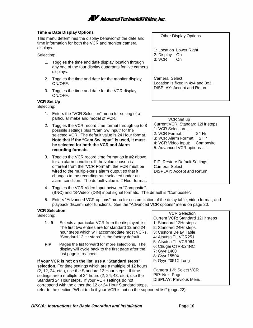
Time & Date Display OptionsThis menu determines the display behavior of the date andtime information for both the VCR and monitor cameradisplays.
Selecting:
1. Toggles the time and date display location throughany one of the four display quadrants for live cameradisplays.
2. Toggles the time and date for the monitor displayON/OFF.
3. Toggles the time and date for the VCR displayON/OFF.
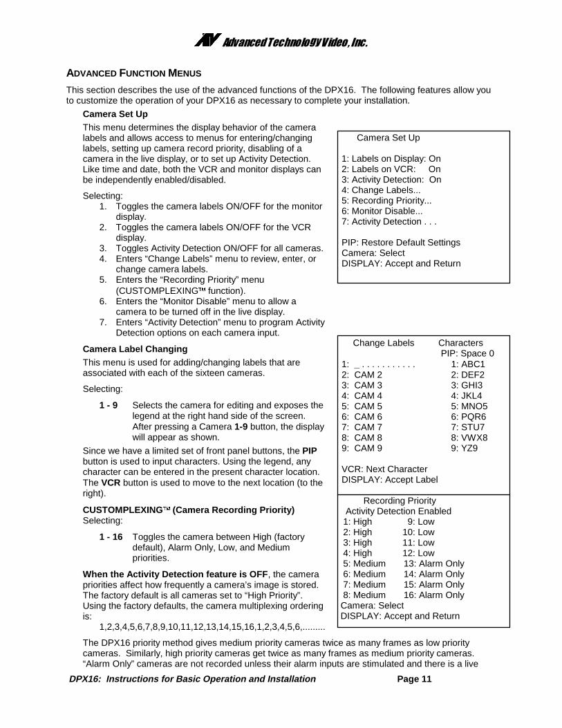
VCR Set UpSelecting:
1. Enters the “VCR Selection” menu for setting of aparticular make and model of VCR.
2. Toggles the VCR record time format through up to 8possible settings plus “Cam Sw Input” for theselected VCR. The default value is 24 Hour format.Note that if the “Cam Sw Input” is used, it mustbe selected for both the VCR and Alarmrecording formats .
3. Toggles the VCR record time format as in #2 abovefor an alarm condition. If the value chosen isdifferent from the “VCR Format”, the VCR must bewired to the multiplexer’s alarm output so that itchanges to the recording rate selected under analarm condition. The default value is 2 Hour format.
4. Toggles the VCR Video Input between “Composite”(BNC) and “S-Video” (DIN) input signal formats. The default is “Composite”.
5. Enters “Advanced VCR options” menu for customization of the delay table, video format, andplayback discriminator functions. See the “Advanced VCR options” menu on page 20.
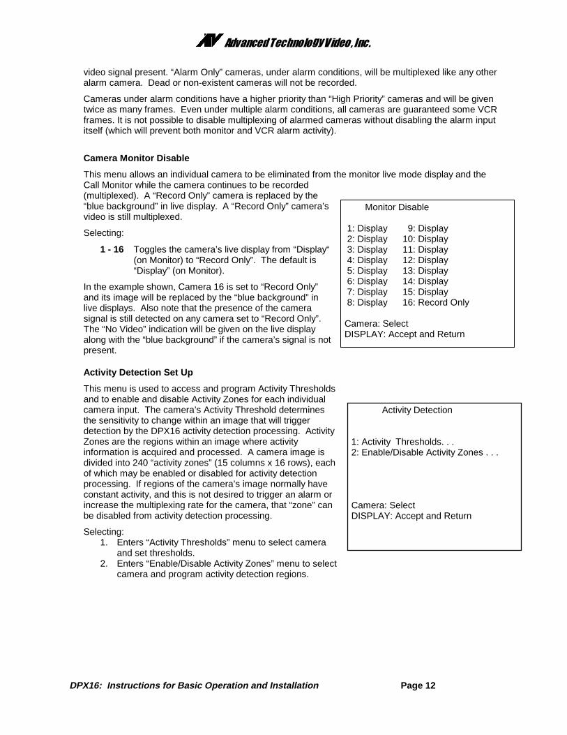
VCR SelectionSelecting:
1 - 9 Selects a particular VCR from the displayed list.The first two entries are for standard 12 and 24hour steps which will accommodate most VCRs.“Standard 12 Hr steps” is the factory default.
PIP Pages the list forward for more selections. Thedisplay will cycle back to the first page after thelast page is reached.
If your VCR is not on the list, use a “Standard steps”selection . For time settings which are a multiple of 12 hours(2, 12, 24, etc.), use the Standard 12 Hour steps. If timesettings are a multiple of 24 hours (2, 24, 48, etc.), use theStandard 24 Hour steps. If your VCR settings do notcorrespond with the either the 12 or 24 Hour Standard steps,refer to the section “What to do if your VCR is not on the supported list” (page 22).
VCR Selection Current VCR: Standard 12Hr steps 1: Standard 12Hr steps 2: Standard 24Hr steps 3: Custom Delay Table 4: Atsutsa TL VCR251 5: Atsutsa TL VCR964 6: Chugai CTR-024NC 7: Gyyr 1400 8: Gyyr 1550X 9: Gyyr 2051X Long
Camera 1-9: Select VCR PIP: Next Page DISPLAY: Previous Menu
Other Display Options
1: Location Lower Right 2: Display On 3: VCR On
Camera: Select Location is fixed in 4x4 and 3x3. DISPLAY: Accept and Return
VCR Set up Current VCR: Standard 12Hr steps 1: VCR Selection . . . 2: VCR Format: 24 Hr 3: VCR Alarm Format: 2 Hr 4: VCR Video Input: Composite 5: Advanced VCR options . . .
PIP: Restore Default Settings Camera: Select DISPLAY: Accept and Return
��������������� �������������
DPX16: Instructions for Basic Operation and Installation Page 11
ADVANCED FUNCTION MENUS
This section describes the use of the advanced functions of the DPX16. The following features allow youto customize the operation of your DPX16 as necessary to complete your installation.
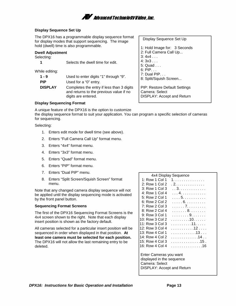
Camera Set UpThis menu determines the display behavior of the cameralabels and allows access to menus for entering/changinglabels, setting up camera record priority, disabling of acamera in the live display, or to set up Activity Detection.Like time and date, both the VCR and monitor displays canbe independently enabled/disabled.
Selecting:1. Toggles the camera labels ON/OFF for the monitor
display.2. Toggles the camera labels ON/OFF for the VCR
display.3. Toggles Activity Detection ON/OFF for all cameras.4. Enters “Change Labels” menu to review, enter, or
change camera labels.5. Enters the “Recording Priority” menu
(CUSTOMPLEXING� function).6. Enters the “Monitor Disable” menu to allow a
camera to be turned off in the live display.7. Enters “Activity Detection” menu to program Activity
Detection options on each camera input.
Camera Label ChangingThis menu is used for adding/changing labels that areassociated with each of the sixteen cameras.
Selecting:
1 - 9 Selects the camera for editing and exposes thelegend at the right hand side of the screen.After pressing a Camera 1-9 button, the displaywill appear as shown.
Since we have a limited set of front panel buttons, the PIPbutton is used to input characters. Using the legend, anycharacter can be entered in the present character location.The VCR button is used to move to the next location (to theright).
1 - 16 Toggles the camera between High (factorydefault), Alarm Only, Low, and Mediumpriorities.
When the Activity Detection feature is OFF , the camerapriorities affect how frequently a camera’s image is stored.The factory default is all cameras set to “High Priority”.Using the factory defaults, the camera multiplexing orderingis:
The DPX16 priority method gives medium priority cameras twice as many frames as low prioritycameras. Similarly, high priority cameras get twice as many frames as medium priority cameras.“Alarm Only” cameras are not recorded unless their alarm inputs are stimulated and there is a live
Recording Priority Activity Detection Enabled 1: High 9: Low 2: High 10: Low 3: High 11: Low 4: High 12: Low 5: Medium 13: Alarm Only 6: Medium 14: Alarm Only 7: Medium 15: Alarm Only 8: Medium 16: Alarm Only Camera: Select DISPLAY: Accept and Return
Camera Set Up
1: Labels on Display: On 2: Labels on VCR: On 3: Activity Detection: On 4: Change Labels... 5: Recording Priority... 6: Monitor Disable... 7: Activity Detection . . .
PIP: Restore Default Settings Camera: Select DISPLAY: Accept and Return
DPX16: Instructions for Basic Operation and Installation Page 12
video signal present. “Alarm Only” cameras, under alarm conditions, will be multiplexed like any otheralarm camera. Dead or non-existent cameras will not be recorded.
Cameras under alarm conditions have a higher priority than “High Priority” cameras and will be giventwice as many frames. Even under multiple alarm conditions, all cameras are guaranteed some VCRframes. It is not possible to disable multiplexing of alarmed cameras without disabling the alarm inputitself (which will prevent both monitor and VCR alarm activity).
Camera Monitor Disable
This menu allows an individual camera to be eliminated from the monitor live mode display and theCall Monitor while the camera continues to be recorded(multiplexed). A “Record Only” camera is replaced by the“blue background” in live display. A “Record Only” camera’svideo is still multiplexed.
Selecting:
1 - 16 Toggles the camera’s live display from “Display“(on Monitor) to “Record Only”. The default is“Display” (on Monitor).
In the example shown, Camera 16 is set to “Record Only”and its image will be replaced by the “blue background” inlive displays. Also note that the presence of the camerasignal is still detected on any camera set to “Record Only”.The “No Video” indication will be given on the live displayalong with the “blue background” if the camera’s signal is notpresent.
Activity Detection Set Up
This menu is used to access and program Activity Thresholdsand to enable and disable Activity Zones for each individualcamera input. The camera’s Activity Threshold determinesthe sensitivity to change within an image that will triggerdetection by the DPX16 activity detection processing. ActivityZones are the regions within an image where activityinformation is acquired and processed. A camera image isdivided into 240 “activity zones” (15 columns x 16 rows), eachof which may be enabled or disabled for activity detectionprocessing. If regions of the camera’s image normally haveconstant activity, and this is not desired to trigger an alarm orincrease the multiplexing rate for the camera, that “zone” canbe disabled from activity detection processing.
Selecting:1. Enters “Activity Thresholds” menu to select camera
and set thresholds.2. Enters “Enable/Disable Activity Zones” menu to select
Enter Cameras you want displayed in the sequence Camera: Select DISPLAY: Accept and Return
Display Sequence Set Up
The DPX16 has a programmable display sequence formatfor display modes that support sequencing. The imagehold (dwell) time is also programmable.
Dwell AdjustmentSelecting:
1 Selects the dwell time for edit.
While editing:1 - 9 Used to enter digits “1” through “9”.PIP Used for a “0” entry.DISPLAY Completes the entry if less than 3 digits
and returns to the previous value if nodigits are entered.
Display Sequencing Format
A unique feature of the DPX16 is the option to customizethe display sequence format to suit your application. You can program a specific selection of camerasfor sequencing.
Note that any changed camera display sequence will notbe applied until the display sequencing mode is activatedby the front panel button.
Sequencing Format Screens
The first of the DPX16 Sequencing Format Screens is the4x4 screen shown to the right. Note that each displayinsert position is shown as the factory default.
All cameras selected for a particular insert position will besequenced in order when displayed in that position. Atleast one camera must be selected for each position.The DPX16 will not allow the last remaining entry to bedeleted.
PIP: Restore Default Settings Camera: Select DISPLAY: Accept and Return
��������������� �������������
DPX16: Instructions for Basic Operation and Installation Page 14
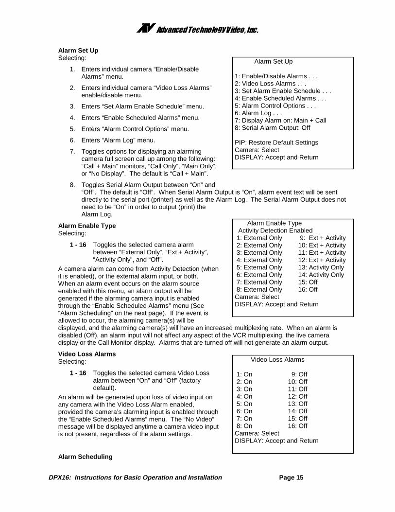
The above screens show the factory default values. You can customize any or all formats, and mayhave more than one section of a multi-camera display defined for sequencing. For any particularcamera display, cameras are sequenced in ascending numerical order and cameras cannot berepeated.
3x3 Display Sequence 1: Top Left 1. . . . . . . .10. . . . . . 2: Top Center . 2. . . . . . . .11. . . . . 3: Top Right . . 3. . . . . . . .12. . . . 4: Center Left . . . 4. . . . . . . .13. . . 5: Center . . . . 5. . . . . . . .14. . 6: Center Right . . . . . 6. . . . . . . .15. 7: Bottom Left . . . . . . 7. . . . . . . .16 8: Bottom Center . . . . . . . 8. . . . . . . . 9: Bottom Right . . . . . . . . 9. . . . . . . Enter Cameras you want displayed in the sequence Camera: Select DISPLAY: Accept and Return
Full Camera Display Sequence
1: Cameras: 12345678910111213141516
Enter Cameras you want displayed in the sequence
Camera: Select DISPLAY: Accept and Return
PIP Display Sequence
1: Background: As is 2: Insert: 12345678910111213141516
Enter Cameras you want displayed in the sequence
Camera: Select DISPLAY: Accept and Return
Dual PIP Display Sequence
1: Background: As is 2: Insert 1: 12345678910111213141516 3: Insert 2: As is
DPX16: Instructions for Basic Operation and Installation Page 15
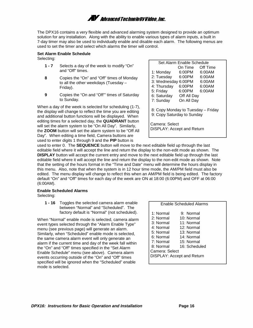
Alarm Set UpSelecting:
1. Enters individual camera “Enable/DisableAlarms” menu.
2. Enters individual camera “Video Loss Alarms”enable/disable menu.
3. Enters “Set Alarm Enable Schedule” menu.
4. Enters “Enable Scheduled Alarms” menu.
5. Enters “Alarm Control Options” menu.
6. Enters “Alarm Log” menu.
7. Toggles options for displaying an alarmingcamera full screen call up among the following:“Call + Main” monitors, “Call Only”, “Main Only”,or “No Display”. The default is “Call + Main”.
8. Toggles Serial Alarm Output between “On” and“Off”. The default is “Off”. When Serial Alarm Output is “On”, alarm event text will be sentdirectly to the serial port (printer) as well as the Alarm Log. The Serial Alarm Output does notneed to be “On” in order to output (print) theAlarm Log.
Alarm Enable TypeSelecting:
1 - 16 Toggles the selected camera alarmbetween “External Only”, “Ext + Activity”,“Activity Only”, and “Off”.
A camera alarm can come from Activity Detection (whenit is enabled), or the external alarm input, or both.When an alarm event occurs on the alarm sourceenabled with this menu, an alarm output will begenerated if the alarming camera input is enabledthrough the “Enable Scheduled Alarms” menu (See“Alarm Scheduling” on the next page). If the event isallowed to occur, the alarming camera(s) will bedisplayed, and the alarming camera(s) will have an increased multiplexing rate. When an alarm isdisabled (Off), an alarm input will not affect any aspect of the VCR multiplexing, the live cameradisplay or the Call Monitor display. Alarms that are turned off will not generate an alarm output.
Video Loss AlarmsSelecting:
1 - 16 Toggles the selected camera Video Lossalarm between “On” and “Off” (factorydefault).
An alarm will be generated upon loss of video input onany camera with the Video Loss Alarm enabled,provided the camera’s alarming input is enabled throughthe “Enable Scheduled Alarms” menu. The “No Video”message will be displayed anytime a camera video inputis not present, regardless of the alarm settings.
Alarm Scheduling
Alarm Enable Type Activity Detection Enabled 1: External Only 9: Ext + Activity 2: External Only 10: Ext + Activity 3: External Only 11: Ext + Activity 4: External Only 12: Ext + Activity 5: External Only 13: Activity Only 6: External Only 14: Activity Only 7: External Only 15: Off 8: External Only 16: Off Camera: Select DISPLAY: Accept and Return
Alarm Set Up
1: Enable/Disable Alarms . . . 2: Video Loss Alarms . . . 3: Set Alarm Enable Schedule . . . 4: Enable Scheduled Alarms . . . 5: Alarm Control Options . . . 6: Alarm Log . . . 7: Display Alarm on: Main + Call 8: Serial Alarm Output: Off
PIP: Restore Default Settings Camera: Select DISPLAY: Accept and Return
Video Loss Alarms
1: On 9: Off 2: On 10: Off 3: On 11: Off 4: On 12: Off 5: On 13: Off 6: On 14: Off 7: On 15: Off 8: On 16: Off Camera: Select DISPLAY: Accept and Return
��������������� �������������
DPX16: Instructions for Basic Operation and Installation Page 16
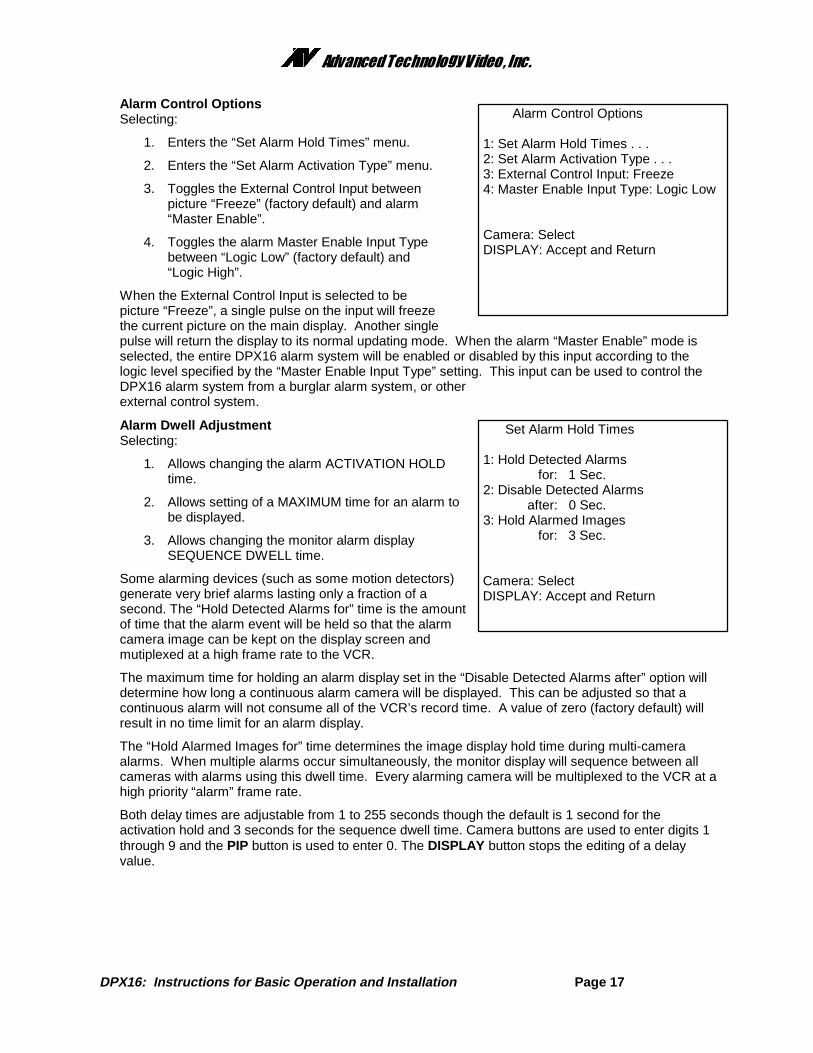
The DPX16 contains a very flexible and advanced alarming system designed to provide an optimumsolution for any installation. Along with the ability to enable various types of alarm inputs, a built in7-day timer may also be used to individually enable and disable each alarm. The following menus areused to set the timer and select which alarms the timer will control.
Set Alarm Enable ScheduleSelecting:
1 - 7 Selects a day of the week to modify “On”and “Off” times.
8 Copies the “On” and “Off” times of Mondayto all the other weekdays (Tuesday –Friday).
9 Copies the “On and “Off’” times of Saturdayto Sunday.
When a day of the week is selected for scheduling (1-7),the display will change to reflect the time you are editingand additional button functions will be displayed. Whenediting times for a selected day, the QUADRANT buttonwill set the alarm system to be “On All Day”. Similarly,the ZOOM button will set the alarm system to be “Off AllDay”. When editing a time field, Camera buttons areused to enter digits 1 through 9 and the PIP button isused to enter 0. The SEQUENCE button will move to the next editable field up through the lasteditable field where it will accept the line and return the display to the non-edit mode as shown. TheDISPLAY button will accept the current entry and move to the next editable field up through the lasteditable field where it will accept the line and return the display to the non-edit mode as shown. Notethat the setting of the hours format in the “Time and Date” menu will determine the hours display inthis menu. Also, note that when the system is in 12 hour time mode, the AM/PM field must also beedited. The menu display will change to reflect this when an AM/PM field is being edited. The factorydefault “On” and “Off” times for each day of the week are ON at 18:00 (6:00PM) and OFF at 06:00(6:00AM).
Enable Scheduled AlarmsSelecting:
1 - 16 Toggles the selected camera alarm enablebetween “Normal” and “Scheduled”. Thefactory default is “Normal” (not scheduled).
When “Normal” enable mode is selected, camera alarmevent types selected through the “Alarm Enable Type”menu (see previous page) will generate an alarm.Similarly, when “Scheduled” enable mode is selected,the same camera alarm event will only generate analarm if the current time and day of the week fall withinthe “On” and “Off” times specified in the “Set AlarmEnable Schedule” menu (see above). Camera alarmevents occurring outside of the “On” and “Off” timesspecified will be ignored when the “Scheduled” enablemode is selected.
Set Alarm Enable Schedule On Time Off Time 1: Monday 6:00PM 6:00AM 2: Tuesday 6:00PM 6:00AM 3: Wednesday 6:00PM 6:00AM 4: Thursday 6:00PM 6:00AM 5: Friday 6:00PM 6:00AM 6: Saturday Off All Day 7: Sunday On All Day
8: Copy Monday to Tuesday – Friday 9: Copy Saturday to Sunday
Camera: Select DISPLAY: Accept and Return
Enable Scheduled Alarms
1: Normal 9: Normal 2: Normal 10: Normal 3: Normal 11: Normal 4: Normal 12: Normal 5: Normal 13: Normal 6: Normal 14: Normal 7: Normal 15: Normal 8: Normal 16: Scheduled Camera: Select DISPLAY: Accept and Return
��������������� �������������
DPX16: Instructions for Basic Operation and Installation Page 17
Alarm Control OptionsSelecting:
1. Enters the “Set Alarm Hold Times” menu.
2. Enters the “Set Alarm Activation Type” menu.
3. Toggles the External Control Input betweenpicture “Freeze” (factory default) and alarm“Master Enable”.
When the External Control Input is selected to bepicture “Freeze”, a single pulse on the input will freezethe current picture on the main display. Another singlepulse will return the display to its normal updating mode. When the alarm “Master Enable” mode isselected, the entire DPX16 alarm system will be enabled or disabled by this input according to thelogic level specified by the “Master Enable Input Type” setting. This input can be used to control theDPX16 alarm system from a burglar alarm system, or otherexternal control system.
Alarm Dwell AdjustmentSelecting:
1. Allows changing the alarm ACTIVATION HOLDtime.
2. Allows setting of a MAXIMUM time for an alarm tobe displayed.
3. Allows changing the monitor alarm displaySEQUENCE DWELL time.
Some alarming devices (such as some motion detectors)generate very brief alarms lasting only a fraction of asecond. The “Hold Detected Alarms for” time is the amountof time that the alarm event will be held so that the alarmcamera image can be kept on the display screen andmutiplexed at a high frame rate to the VCR.
The maximum time for holding an alarm display set in the “Disable Detected Alarms after” option willdetermine how long a continuous alarm camera will be displayed. This can be adjusted so that acontinuous alarm will not consume all of the VCR’s record time. A value of zero (factory default) willresult in no time limit for an alarm display.
The “Hold Alarmed Images for” time determines the image display hold time during multi-cameraalarms. When multiple alarms occur simultaneously, the monitor display will sequence between allcameras with alarms using this dwell time. Every alarming camera will be multiplexed to the VCR at ahigh priority “alarm” frame rate.
Both delay times are adjustable from 1 to 255 seconds though the default is 1 second for theactivation hold and 3 seconds for the sequence dwell time. Camera buttons are used to enter digits 1through 9 and the PIP button is used to enter 0. The DISPLAY button stops the editing of a delayvalue.
Set Alarm Hold Times
1: Hold Detected Alarms for: 1 Sec. 2: Disable Detected Alarms
after: 0 Sec. 3: Hold Alarmed Images for: 3 Sec.
Camera: Select DISPLAY: Accept and Return
Alarm Control Options
1: Set Alarm Hold Times . . . 2: Set Alarm Activation Type . . . 3: External Control Input: Freeze 4: Master Enable Input Type: Logic Low
Camera: Select DISPLAY: Accept and Return
��������������� �������������
DPX16: Instructions for Basic Operation and Installation Page 18
Alarm Activation TypeSelecting:
1 - 16 Toggles the selected camera between“Contact Closure”, “Contact Open”, “LogicLow”, or “Logic High” triggering the alarm.
In many applications the switch contact connection isbetween the alarm input pin and the chassis or signalground. In the DPX16 the contact connection can bebetween either the ground (alarm connector pin 15) orthe +5V (alarm connector pin 13). In some alarmingdevices this is not a metallic switch contact but rathera solid state device which “grounds” (Logic Low) theinput as a normal condition or as an alarm condition.The four activation modes are provided to simplifyconnection to most alarm sources. See “AlarmInterconnection on the DPX16” on page 24. Thedefault Alarm Activation Type is “Contact Closure”.
The DPX16 alarm activation is defined as follows:
Contact Closure: The alarm pin is connected to a current source (either +5V or ground).
Contact Open: The alarm pin is not connected to any current source (unconnected pin).
Logic Low: A logic “low” level less than 0.8V (ground) is present at the alarm pin.
Logic High: A logic “high” level greater than 2.4V (+5V) is present at the alarm pin.
Alarm Log
The Alarm Log menu is used to view the currentcontents of the internal Alarm Log and to clear the logor transmit the log contents to the serial port forprinting. The Alarm Log contains the time, date,camera number, and type of alarm for each alarm eventthat has been stored. The Alarm Log can store up to100 alarm events at which point new alarm eventscontinue to be stored and replace the oldest event inthe buffer. An “Overflow” message is displayed in theupper left corner of the Alarm Log menu if more than100 events have occurred indicating older alarm eventshave been displaced. An alarm event is generatedwhen any enabled and valid scheduled External,Activity, or Video Loss alarm occurs (See “AlarmScheduling” onpage 15). The Alarm Log is a very useful tool forreviewing the VCR recording allowing rapid location andreview of recorded video time periods of interest.
The Alarm Log may be printed on a serial interfaceprinter which is connected to the DPX16 Serial Port. The log may also be sent to a host computer forstorage or processing rather than a printer.
The Alarm Log can be cleared by pressing the ZOOM button.
Up Arrow: Next VCR: Print Log Down Arrow: Prev Zoom: Clear Log DISPLAY: Return
��������������� �������������
DPX16: Instructions for Basic Operation and Installation Page 19
Other Options
The “Other Options” menu provides access to theadvanced DPX16 systems options.
Selecting:
1. Toggles the IR remote control code settingbetween Code 1, Code 2, and remote OFF.(See “Hand Held IR Remote Control” on page21.)
2. Enters the “Security Set Up” menu forestablishing a security lockout code.
3. Toggles On-screen text color between “White”,“Yellow”, “Cyan”, and “Green”.
4. Toggles the black text background ON andOFF.
Security Set Up
Security lockout is a means to disable the DPX16 menusso that casual or inadvertent tampering can be prevented.It is not intended as a hard security measure and can bebypassed by removing the DPX16 power followed byapplying power and simultaneously pressing theDISPLAY button until the ATV name appears. This is notthe preferred method of bypassing security since this stepalso returns all internal parameters and options to theirfactory defaults.
The security feature requires that a security code(“password”) of 1 to 9 digits be entered and verified. Thesecurity lockout does not become active until the menushave been exited. “Button Lock”, when “On”, will disable all front panel operations. A long press ofthe DISPLAY button will still enable menus. “Security IR Lock” and “Serial Lock”, when “On”, willdisable all IR remote control button and serial interface operations respectively.
Other Options
1: Remote Control: Code 2 2: Security Set Up . . . 3: Text Color: White 4: Text Background: Off
PIP: Restore ALL Settings to Factory Defaults Camera: Select DISPLAY: Accept and Return
Security Set Up
Menus are Unlocked
1: Lock Menus 2: Unlock Menus 3: Button Lock: Off 4: Security IR Lock: Off 5: Serial Lock: Off
Camera: Select DISPLAY: Accept and Return
��������������� �������������
DPX16: Instructions for Basic Operation and Installation Page 20
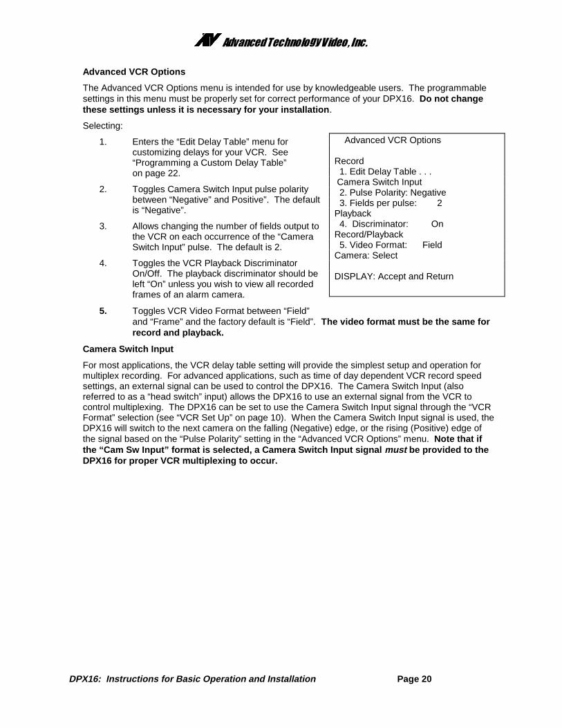
Advanced VCR Options
The Advanced VCR Options menu is intended for use by knowledgeable users. The programmablesettings in this menu must be properly set for correct performance of your DPX16. Do not changethese settings unless it is necessary for your installation .
Selecting:
1. Enters the “Edit Delay Table” menu forcustomizing delays for your VCR. See“Programming a Custom Delay Table”on page 22.
2. Toggles Camera Switch Input pulse polaritybetween “Negative” and Positive”. The defaultis “Negative”.
3. Allows changing the number of fields output tothe VCR on each occurrence of the “CameraSwitch Input” pulse. The default is 2.
4. Toggles the VCR Playback DiscriminatorOn/Off. The playback discriminator should beleft “On” unless you wish to view all recordedframes of an alarm camera.
5. Toggles VCR Video Format between “Field”and “Frame” and the factory default is “Field”. The video format must be the same forrecord and playback.
Camera Switch Input
For most applications, the VCR delay table setting will provide the simplest setup and operation formultiplex recording. For advanced applications, such as time of day dependent VCR record speedsettings, an external signal can be used to control the DPX16. The Camera Switch Input (alsoreferred to as a “head switch” input) allows the DPX16 to use an external signal from the VCR tocontrol multiplexing. The DPX16 can be set to use the Camera Switch Input signal through the “VCRFormat” selection (see “VCR Set Up” on page 10). When the Camera Switch Input signal is used, theDPX16 will switch to the next camera on the falling (Negative) edge, or the rising (Positive) edge ofthe signal based on the “Pulse Polarity” setting in the “Advanced VCR Options” menu. Note that ifthe “Cam Sw Input” format is selected, a Camera Switch Input signal must be provided to theDPX16 for proper VCR multiplexing to occur.
Advanced VCR Options
Record 1. Edit Delay Table . . . Camera Switch Input 2. Pulse Polarity: Negative 3. Fields per pulse: 2 Playback 4. Discriminator: On Record/Playback 5. Video Format: Field Camera: Select
DISPLAY: Accept and Return
��������������� �������������
DPX16: Instructions for Basic Operation and Installation Page 21
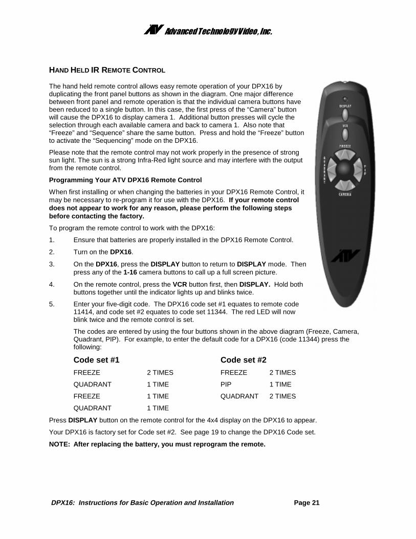
HAND HELD IR REMOTE CONTROL
The hand held remote control allows easy remote operation of your DPX16 byduplicating the front panel buttons as shown in the diagram. One major differencebetween front panel and remote operation is that the individual camera buttons havebeen reduced to a single button. In this case, the first press of the “Camera” buttonwill cause the DPX16 to display camera 1. Additional button presses will cycle theselection through each available camera and back to camera 1. Also note that“Freeze” and “Sequence” share the same button. Press and hold the “Freeze” buttonto activate the “Sequencing” mode on the DPX16.
Please note that the remote control may not work properly in the presence of strongsun light. The sun is a strong Infra-Red light source and may interfere with the outputfrom the remote control.
Programming Your ATV DPX16 Remote Control
When first installing or when changing the batteries in your DPX16 Remote Control, itmay be necessary to re-program it for use with the DPX16. If your remote controldoes not appear to work for any reason, please perform the following stepsbefore contacting the factory.
To program the remote control to work with the DPX16:
1. Ensure that batteries are properly installed in the DPX16 Remote Control.
2. Turn on the DPX16.
3. On the DPX16, press the DISPLAY button to return to DISPLAY mode. Thenpress any of the 1-16 camera buttons to call up a full screen picture.
4. On the remote control, press the VCR button first, then DISPLAY. Hold bothbuttons together until the indicator lights up and blinks twice.
5. Enter your five-digit code. The DPX16 code set #1 equates to remote code11414, and code set #2 equates to code set 11344. The red LED will nowblink twice and the remote control is set.
The codes are entered by using the four buttons shown in the above diagram (Freeze, Camera,Quadrant, PIP). For example, to enter the default code for a DPX16 (code 11344) press thefollowing:
Code set #1 Code set #2
FREEZE 2 TIMES FREEZE 2 TIMES
QUADRANT 1 TIME PIP 1 TIME
FREEZE 1 TIME QUADRANT 2 TIMES
QUADRANT 1 TIME
Press DISPLAY button on the remote control for the 4x4 display on the DPX16 to appear.
Your DPX16 is factory set for Code set #2. See page 19 to change the DPX16 Code set.
NOTE: After replacing the battery, you must reprogram the remote.
��������������� �������������
DPX16: Instructions for Basic Operation and Installation Page 22
WHAT TO DO IF YOUR VCR IS NOT ON THE SUPPORTED LIST
The delay tables contained in DPX16 software should give you satisfactory performance for any of theVCRs listed. If your VCR is not on the list, the process to set up the DPX16 to support your VCR is verystraightforward.
Most non-Real-Time Time Lapse VCRs are of the formula A or B type described below. It is usuallypossible to determine what type of VCR you have from the VCR’s manual. The manual should containvideo delay times for the VCR’s supported hourly formats. The “rule of thumb” for NTSC systems is thatyou take a published delay time (in seconds) and multiply by 60 (50 for PAL). The result should be anumber which is close to either 1/2 the record hourly rate (Formula A) or 1/3 the record hourly rate(Formula B). For example:
1. Your manual states that in 24 Hr mode the picture delay time is 0.21 seconds.
2. 0.21 x 60 = 12.6 (0.21 x 50 = 10.5 for PAL)
3. 12.6 is closer to 12, the 24 hour record rate divided by 2, than to 8, the 24 hour record ratedivided by 3.
4. This means that your VCR is a Formula A type, so you should use the STANDARD 24 HRSTEPS or STANDARD 12 HR STEPS setting (see VCR Selection on page 10).
If your VCR is Real-Time, High Density, not a Formula A or B type or if the VCR does not have 12 or 24hour standard steps, you will need to construct a Custom Delay Table as described in the next section.
PROGRAMMING A CUSTOM DELAY TABLE (ADVANCED OPTION)
The DPX16 has a means of creating and/or modifying a delay table to match your particular VCR.Satisfactory performance can be obtained by setting up the one or two formats you actually plan to useaccording to the following basic guidelines.
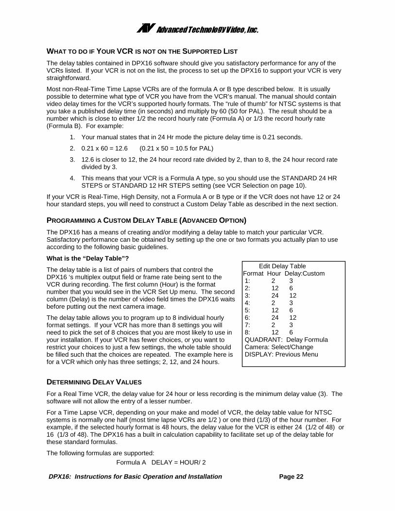
What is the “Delay Table”?
The delay table is a list of pairs of numbers that control theDPX16 ‘s multiplex output field or frame rate being sent to theVCR during recording. The first column (Hour) is the formatnumber that you would see in the VCR Set Up menu. The secondcolumn (Delay) is the number of video field times the DPX16 waitsbefore putting out the next camera image.
The delay table allows you to program up to 8 individual hourlyformat settings. If your VCR has more than 8 settings you willneed to pick the set of 8 choices that you are most likely to use inyour installation. If your VCR has fewer choices, or you want torestrict your choices to just a few settings, the whole table shouldbe filled such that the choices are repeated. The example here isfor a VCR which only has three settings; 2, 12, and 24 hours.
DETERMINING DELAY VALUES
For a Real Time VCR, the delay value for 24 hour or less recording is the minimum delay value (3). Thesoftware will not allow the entry of a lesser number.
For a Time Lapse VCR, depending on your make and model of VCR, the delay table value for NTSCsystems is normally one half (most time lapse VCRs are 1/2 ) or one third (1/3) of the hour number. Forexample, if the selected hourly format is 48 hours, the delay value for the VCR is either 24 (1/2 of 48) or16 (1/3 of 48). The DPX16 has a built in calculation capability to facilitate set up of the delay table forthese standard formulas.
DPX16: Instructions for Basic Operation and Installation Page 23
Formula B DELAY = HOUR/ 3Formula C DELAY = HOURCustom, where the HOUR and DELAY can be independently entered.
Your time-lapse VCR manual should list delay times (in seconds) for each record hour setting. If you havethese values, use the following formula to determine the delay value:
DELAY VALUE = (Delay Time) x 60 for NTSC DELAY VALUE = (Delay Time) x 50 for PAL
For example, if the 24 hour delay time is 0.22 seconds, DELAY = 0.22 x 60 = 13.2
The number will often be a fraction (such as 13.2), so “round” the number to the next nearest wholeinteger (which would be 13). To set up the DPX16 delay entry for this case, you would enter “24” in the“Hours” column and “13” in the “Delay” column.
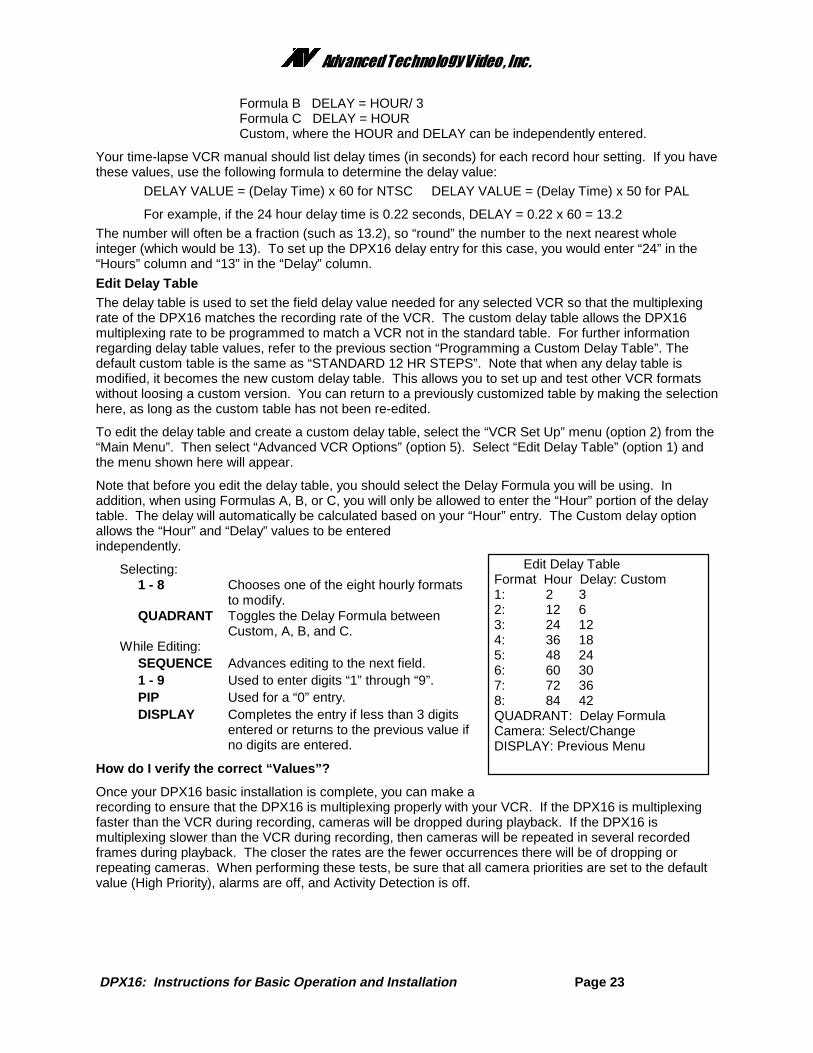
Edit Delay TableThe delay table is used to set the field delay value needed for any selected VCR so that the multiplexingrate of the DPX16 matches the recording rate of the VCR. The custom delay table allows the DPX16multiplexing rate to be programmed to match a VCR not in the standard table. For further informationregarding delay table values, refer to the previous section “Programming a Custom Delay Table”. Thedefault custom table is the same as “STANDARD 12 HR STEPS”. Note that when any delay table ismodified, it becomes the new custom delay table. This allows you to set up and test other VCR formatswithout loosing a custom version. You can return to a previously customized table by making the selectionhere, as long as the custom table has not been re-edited.
To edit the delay table and create a custom delay table, select the “VCR Set Up” menu (option 2) from the“Main Menu”. Then select “Advanced VCR Options” (option 5). Select “Edit Delay Table” (option 1) andthe menu shown here will appear.
Note that before you edit the delay table, you should select the Delay Formula you will be using. Inaddition, when using Formulas A, B, or C, you will only be allowed to enter the “Hour” portion of the delaytable. The delay will automatically be calculated based on your “Hour” entry. The Custom delay optionallows the “Hour” and “Delay” values to be enteredindependently.
Selecting:1 - 8 Chooses one of the eight hourly formats
to modify.QUADRANT Toggles the Delay Formula between
Custom, A, B, and C.While Editing:
SEQUENCE Advances editing to the next field.1 - 9 Used to enter digits “1” through “9”.PIP Used for a “0” entry.DISPLAY Completes the entry if less than 3 digits
entered or returns to the previous value ifno digits are entered.
How do I verify the correct “Values”?
Once your DPX16 basic installation is complete, you can make arecording to ensure that the DPX16 is multiplexing properly with your VCR. If the DPX16 is multiplexingfaster than the VCR during recording, cameras will be dropped during playback. If the DPX16 ismultiplexing slower than the VCR during recording, then cameras will be repeated in several recordedframes during playback. The closer the rates are the fewer occurrences there will be of dropping orrepeating cameras. When performing these tests, be sure that all camera priorities are set to the defaultvalue (High Priority), alarms are off, and Activity Detection is off.
DPX16: Instructions for Basic Operation and Installation Page 24
ALARM INTERCONNECTION ON THE DPX16
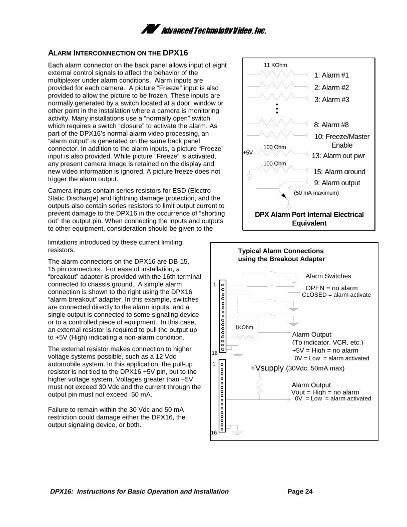
Each alarm connector on the back panel allows input of eightexternal control signals to affect the behavior of themultiplexer under alarm conditions. Alarm inputs areprovided for each camera. A picture “Freeze” input is alsoprovided to allow the picture to be frozen. These inputs arenormally generated by a switch located at a door, window orother point in the installation where a camera is monitoringactivity. Many installations use a “normally open” switchwhich requires a switch “closure” to activate the alarm. Aspart of the DPX16’s normal alarm video processing, an“alarm output” is generated on the same back panelconnector. In addition to the alarm inputs, a picture “Freeze”input is also provided. While picture “Freeze” is activated,any present camera image is retained on the display andnew video information is ignored. A picture freeze does nottrigger the alarm output.
Camera inputs contain series resistors for ESD (ElectroStatic Discharge) and lightning damage protection, and theoutputs also contain series resistors to limit output current toprevent damage to the DPX16 in the occurrence of “shortingout” the output pin. When connecting the inputs and outputsto other equipment, consideration should be given to the
limitations introduced by these current limitingresistors.
The alarm connectors on the DPX16 are DB-15,15 pin connectors. For ease of installation, a“breakout” adapter is provided with the 16th terminalconnected to chassis ground. A simple alarmconnection is shown to the right using the DPX16“alarm breakout” adapter. In this example, switchesare connected directly to the alarm inputs, and asingle output is connected to some signaling deviceor to a controlled piece of equipment. In this case,an external resistor is required to pull the output upto +5V (High) indicating a non-alarm condition.
The external resistor makes connection to highervoltage systems possible, such as a 12 Vdcautomobile system. In this application, the pull-upresistor is not tied to the DPX16 +5V pin, but to thehigher voltage system. Voltages greater than +5Vmust not exceed 30 Vdc and the current through theoutput pin must not exceed 50 mA.
Failure to remain within the 30 Vdc and 50 mArestriction could damage either the DPX16, theoutput signaling device, or both.
1: Alarm #1
2: Alarm #2
3: Alarm #3
8: Alarm #8
11 KOhm
100 Ohm
100 Ohm
+5V
10: Freeze/MasterEnable
13: Alarm out pwr
15: Alarm ground
9: Alarm output
DPX Alarm Port Internal ElectricalEquivalent
(50 mA maximum)
Typical Alarm Connectionsusing the Breakout Adapter
Alarm Switches
OPEN = no alarmCLOSED = alarm activate
1KOhm
+Vsupply (30Vdc, 50mA max)
Alarm Output(To indicator, VCR, etc.)+5V = High = no alarm 0V = Low = alarm activated
Alarm OutputVout = High = no alarm 0V = Low = alarm activated
1
16
1
16
��������������� �������������
DPX16: Instructions for Basic Operation and Installation Page 25
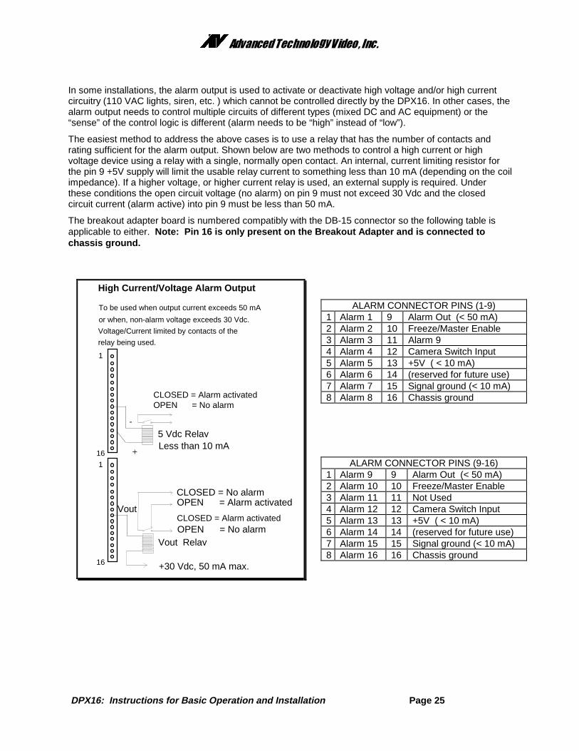
In some installations, the alarm output is used to activate or deactivate high voltage and/or high currentcircuitry (110 VAC lights, siren, etc. ) which cannot be controlled directly by the DPX16. In other cases, thealarm output needs to control multiple circuits of different types (mixed DC and AC equipment) or the“sense” of the control logic is different (alarm needs to be “high” instead of “low”).
The easiest method to address the above cases is to use a relay that has the number of contacts andrating sufficient for the alarm output. Shown below are two methods to control a high current or highvoltage device using a relay with a single, normally open contact. An internal, current limiting resistor forthe pin 9 +5V supply will limit the usable relay current to something less than 10 mA (depending on the coilimpedance). If a higher voltage, or higher current relay is used, an external supply is required. Underthese conditions the open circuit voltage (no alarm) on pin 9 must not exceed 30 Vdc and the closedcircuit current (alarm active) into pin 9 must be less than 50 mA.
The breakout adapter board is numbered compatibly with the DB-15 connector so the following table isapplicable to either. Note: Pin 16 is only present on the Breakout Adapter and is connected tochassis ground.
DPX16: Instructions for Basic Operation and Installation Page 26
RS-232 REMOTE CONTROL INTERFACE
The DPX16 has a built in RS-232 serial interface, which supports remote control of the DPX16 throughsimple ASCII commands. These commands provide access to the front panel button operations just asthe IR Remote Control does.The DPX16 serial interface is fixed at 9600 baud, 8 bits, 1 stop bit, and no parity. The command format is:
<command> <return>
The command is 2 characters or 2 characters plus parameter and must be followed by a “carriage return”.The DPX16 will respond with:
> if the command was recognized, or? if the command was not recognized or is invalid
The following commands are supported by the DPX16 serial interface:BD Display ButtonBS Sequence Button - will cause DPX16 to begin sequencingBP Pip ButtonBQ Quadrant ButtonBV VCR Button - will cause the DPX16 to enter or exit VCR playback mode or “zoom out”BF Freeze Button - will cause the DPX16 to freeze current display videoBB VCR Bypass - will cause the DPX16 to enter or exit the VCR bypass modeBZ Zoom Button - will cause the DPX16 to enter Zoom mode or “zoom in” in Zoom modeBCn Camera Button - n is a number 1 through 16 corresponding to the camera number. There
must be no “space” or “tab” entered between the command and the number.BL n Button Lock - n=0 sets front panel button lock OFF, and n=1 sets button lock ON.CM Call Monitor - will cause the DPX16 to toggle between “Normal” and “Call Monitor” modes.
When in “Call Monitor” mode, button commands will control Call Monitor functions.DM m,c,c,c,...,q
Set Display Mode - will cause the DPX16 to enter the selected display mode with selectedcameras in the display inserts where m=display mode, c=camera number, q=quadrant.Display modes are as follows: 0=Full screen, 1=2x2, 2=3x3, 3=4x4, 4=PIP, 5=Dual PIP,6=Split screen, 7=Squish screen.
EC n Echo characters - n=0, echo OFF; n=1, echo ON (factory default).HELP Help command - will display a list of commands.MD Move Down - in Zoom mode, will cause the DPX16 display to move down.ML Move Left - in Zoom mode, will cause the DPX16 display to move left.MR Move Right - in Zoom mode, will cause the DPX16 display to move right.MU Move Up - in Zoom mode, will cause the DPX16 display to move up.VER Version - will cause the DPX16 to output the current software version number.
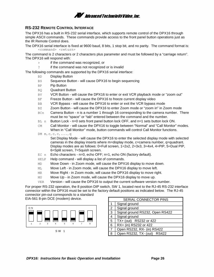
For proper RS-232 operation, the 8 position DIP switch, SW 1, located next to the RJ-45 RS-232 interfaceconnector within the DPX16 must be set to the factory default positions as indicated below. The RJ-45connector pin-out corresponds to a standardEIA-561 8-pin DCE (modem) device. SERIAL CONNECTOR PINS
1 Signal ground2 Signal ground3 Signal ground RS232, Open RS4224 Signal ground5 TX+ (out) RS232 or 4226 RX+ (in) RS232 or 4227 Open RS232, RX- (in) RS4228 Open RS232, TX- (out) RS422
O N
42 53 6 7 81
S W 1
��������������� �������������
DPX16: Instructions for Basic Operation and Installation Page 27
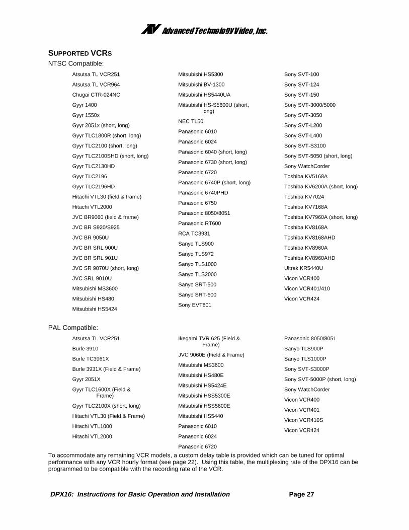
SUPPORTED VCRS
NTSC Compatible:
Atsutsa TL VCR251
Atsutsa TL VCR964
Chugai CTR-024NC
Gyyr 1400
Gyyr 1550x
Gyyr 2051x (short, long)
Gyyr TLC1800R (short, long)
Gyyr TLC2100 (short, long)
Gyyr TLC2100SHD (short, long)
Gyyr TLC2130HD
Gyyr TLC2196
Gyyr TLC2196HD
Hitachi VTL30 (field & frame)
Hitachi VTL2000
JVC BR9060 (field & frame)
JVC BR S920/S925
JVC BR 9050U
JVC BR SRL 900U
JVC BR SRL 901U
JVC SR 9070U (short, long)
JVC SRL 9010U
Mitsubishi MS3600
Mitsubishi HS480
Mitsubishi HS5424
Mitsubishi HS5300
Mitsubishi BV-1300
Mitsubishi HS5440UA
Mitsubishi HS-S5600U (short,long)
NEC TL50
Panasonic 6010
Panasonic 6024
Panasonic 6040 (short, long)
Panasonic 6730 (short, long)
Panasonic 6720
Panasonic 6740P (short, long)
Panasonic 6740PHD
Panasonic 6750
Panasonic 8050/8051
Panasonic RT600
RCA TC3931
Sanyo TLS900
Sanyo TLS972
Sanyo TLS1000
Sanyo TLS2000
Sanyo SRT-500
Sanyo SRT-600
Sony EVT801
Sony SVT-100
Sony SVT-124
Sony SVT-150
Sony SVT-3000/5000
Sony SVT-3050
Sony SVT-L200
Sony SVT-L400
Sony SVT-S3100
Sony SVT-5050 (short, long)
Sony WatchCorder
Toshiba KV5168A
Toshiba KV6200A (short, long)
Toshiba KV7024
Toshiba KV7168A
Toshiba KV7960A (short, long)
Toshiba KV8168A
Toshiba KV8168AHD
Toshiba KV8960A
Toshiba KV8960AHD
Ultrak KR5440U
Vicon VCR400
Vicon VCR401/410
Vicon VCR424
PAL Compatible:
Atsutsa TL VCR251
Burle 3910
Burle TC3961X
Burle 3931X (Field & Frame)
Gyyr 2051X
Gyyr TLC1600X (Field &Frame)
Gyyr TLC2100X (short, long)
Hitachi VTL30 (Field & Frame)
Hitachi VTL1000
Hitachi VTL2000
Ikegami TVR 625 (Field &Frame)
JVC 9060E (Field & Frame)
Mitsubishi MS3600
Mitsubishi HS480E
Mitsubishi HS5424E
Mitsubishi HSS5300E
Mitsubishi HSS5600E
Mitsubishi HS5440
Panasonic 6010
Panasonic 6024
Panasonic 6720
Panasonic 8050/8051
Sanyo TLS900P
Sanyo TLS1000P
Sony SVT-S3000P
Sony SVT-5000P (short, long)
Sony WatchCorder
Vicon VCR400
Vicon VCR401
Vicon VCR410S
Vicon VCR424
To accommodate any remaining VCR models, a custom delay table is provided which can be tuned for optimalperformance with any VCR hourly format (see page 22). Using this table, the multiplexing rate of the DPX16 can beprogrammed to be compatible with the recording rate of the VCR.
��������������� �������������
DPX16: Instructions for Basic Operation and Installation Page 28
EQUIPMENT REQUIREMENTSThe DPX16 is designed to be compatible with all NTSC and PAL compatible equipment. The DPX16 will accept 2:1interlace cameras in either a “line-locked” or “free running” (internal reference) modes. The use of “random interlace”camera is not recommended unless the line lock is turned off.
SPECIFICATIONS
PhysicalDimensions........................................................................... 16.720” w X 8.250” d X 2.250” h
(425 mm X 210 mm X 57 mm)Weight ................................................................................. 7.8 lbs (3.51 kg), Power Supply: 1.0 lbs (0.45 kg)Operating Temp.................................................................... 32�F - 104�F (0�C - 40�C)VideoSignal Format ....................................................................... NTSC/PAL Compatible Color or Monochrome
Camera Inputs ...................................................................... 0.6 to 1.2 Vp-p 75 Ohm TerminationMonitor Output ...................................................................... 1.2 Vp-p into 75 Ohms (S-Video and Composite)VCR Output .......................................................................... 1.2 Vp-p into 75 Ohms (S-Video and Composite)Digital Sampling.................................................................... 720 X 480 NTSC, 720 X 576 PAL
4:2:2 (256 Gray Levels, 16 Million Colors)Refresh Rate......................................................................... 30 Frames Per Second (NTSC)
25 Frames Per Second (PAL)ElectricalPower ................................................................................... 12 V AC @ 2 AmpSafety ................................................................................... 110V, 60Hz Power Supply: UL Listed and CSA Certified
220V, 50Hz Power Supply: CE Mark and VDE approvedEMI ....................................................................................... FCC Part 15, Class A
CE Certified EN50081-1 (emissions), EN50082-1 (immunity)ConnectorsVideo In ................................................................................ BNC, 1 Per Camera, Terminating, or Hi-ZLoop Thru ............................................................................. BNC, 1 Per CameraMonitor Video Out ................................................................. BNC, S-VideoVCR Video In ....................................................................... BNC, S-VideoVCR Video Out ..................................................................... BNC, S-VideoSerial Port ............................................................................. RJ45, EIA 561Alarm ................................................................................... DB15 With Screw On Adapter Board12 VAC, or 12 VDC............................................................... Power Jack, 0.080” Pin DiameterControlsDISPLAY .............................................................................. Return to 4x4 DisplaySEQUENCE.......................................................................... Calls Up Selected Sequence ModeFREEZE ............................................................................... Freeze current display imagePIP........................................................................................ Calls Up Next PIP ModeQUADRANT.......................................................................... Rotates QuadrantZOOM................................................................................... Activates Variable ZoomVCR...................................................................................... Enables/Disables VCR Input for Recorder PlaybackSIXTEEN CAMERA BUTTONS (1-16) .................................. Calls Up Individual Cameras Full ScreenIR Remote ............................................................................ Duplicates Front Panel ControlsTermination Switches............................................................ Selects 75 Ohm or Hi-Z Termination for Video Inputs
��������������� �������������
DPX16: Instructions for Basic Operation and Installation Page 29
WARRANTY INFORMATIONThank you for purchasing this Advanced Technology Video, Inc., hereinafter “ATV”, product. We have manufactured this product inaccordance with high quality standards and when it is used in the manner intended, it has a limited warranty against defects inmaterial and workmanship for a period of five (5) years from the date of shipment from ATV . During the warranty periodATV’s entire liability and your exclusive remedy shall be, at ATV’s option, upon receipt of proof of purchase, repair or replacementof products that prove to be defective. Repair of a defective product is contingent upon availability of replacement parts from theirmanufacturer. Should ATV be unable to obtain replacement parts, ATV will, at its option, pro rate the value of the defective productand offer this amount toward the purchase of any new ATV product.
For warranty service or repair, this product must be returned to a service facility designated by ATV. Within the United States, youmust obtain a return authorization (RMA) number by calling (888) 288-7644. Outside of the United States, contact your salesrepresentative or the ATV factory at 425-885-7000 (email: [email protected]). For ATV factory service after obtaining an RMAnumber, send the product with shipping charges and applicable duties and taxes paid, along with a copy of your sales receipt orother proof of purchase and date of purchase to the ATV factory address.
YEAR 2000 CONFORMANCEAll ATV products containing a date and time function meet Year 2000 Conformity Requirements as specified in BSI DISC PD2000-1 (described below). Year 2000 requirements do not apply to ATV products without a date and time function. ATV products’ dateformat is “Day – Month – Year” where “Year” is a two digit representation of the year. Conformity is defined as follows:
1. No value for the current date will cause any interruption in operation of the product.2. Date-based functionality within the product behaves consistently for dates prior to, during and after year 2000.3. The 2 digit date within the product is implicitly assumed to be greater than 1990.4. Year 2000 is recognized as a leap year.
LIMITATION OF WARRANTYThis warranty covers normal use and does not cover damage which occurs in shipment or failure which results from alteration,accident, misuse, neglect, voltage fluctuations, lightning, water damage (or other acts of God), faulty installation or adjustment ofcontrols, interfacing with non-standard or custom equipment, or improper maintenance.
EXCEPT AS HEREIN EXPRESSLY SET FORTH AND TO THE MAXIMUM EXTENT PERMITTED BY APPLICABLE LAW, ATVOR ANY OF ITS EMPLOYEES SHALL NOT, UNDER ANY CIRCUMSTANCES, BE RESPONSIBLE FOR ANY DIRECT,INDIRECT, INCIDENTAL OR CONSEQUENTIAL DAMAGES, INCLUDING, BUT NOT LIMITED TO, DAMAGE TO THEEQUIPMENT. ATV MAKES NO OTHER WARRANTIES, EXPRESS OR IMPLIED INCLUDING, BUT NOT LIMITED TO THEIMPLIED WARRANTIES OF MERCHANTABILITY, FITNESS FOR A PARTICULAR PURPOSE, TITLE, AND NON-INFRINGEMENT. REMOVAL OR ALTERATION OF THE SERIAL NUMBER WILL VOID THIS WARRANTY.
FCC STATEMENTThis equipment has been tested and found to comply with the limits for a class A digital device, pursuant to part 15 of the FCCRules. These limits are designed to provide reasonable protection against harmful interference when the equipment is operated in acommercial environment. This equipment generates, uses, and can radiate radio frequency energy and, if not installed and used inaccordance with the instruction manual, may cause harmful interference to radio communications. Operation of this equipment in aresidential area is likely to cause harmful interference in which case the user will be required to correct the interference at hisexpense.