Owner's Manual DPI SERIES DIMMER Models 624D and 1212D Models 624A and 1212A 01/23/98 TEATRONICS LIGHTING CONTROLS, INC. 1236 Los Osos Valley Rd., Ste. G Los Osos, CA 93402 Phone: (805) 528-6900 FAX: (805) 528-9345
Transcript
DPI SERIES DIMMER 01/23/98Models 624D, 1212D, 624A, AND 1212A page
TEATRONICS LIGHTING CONTROLS, INC.
Owner's Manual
DPI SERIES DIMMERModels 624D and 1212DModels 624A and 1212A
01/23/98
TEATRONICS LIGHTING CONTROLS,INC.
1236 Los Osos Valley Rd., Ste. GLos Osos, CA 93402
Phone: (805) 528-6900FAX: (805) 528-9345
DPI SERIES DIMMER 01/23/98Models 624D, 1212D, 624A, AND 1212A page
TEATRONICS LIGHTING CONTROLS, INC.
RECEIVING YOUR EQUIPMENT
i
DPI SERIES DIMMER 01/23/98Models 624D, 1212D, 624A, AND 1212A page
TEATRONICS LIGHTING CONTROLS, INC.
i i
INTRODUCTION
DPI SERIES DIMMER 01/23/98Models 624D, 1212D, 624A, AND 1212A page
TEATRONICS LIGHTING CONTROLS, INC.
i i i
TABLE OF CONTENTS
RECEIVING YOUR EQUIPMENT ......................................................................... i
INTRODUCTION .................................................................................................. ii
TABLE OF CONTENTS ................................................................................... iii-iv
TABLES AND DRAWINGS .................................................................................. v
TECHNICAL DATA SHEETS................................................................................. -
SETUP AND CONNECTION................................................................................ 1
DPI SERIES DIMMER 01/23/98Models 624D, 1212D, 624A, AND 1212A page
TEATRONICS LIGHTING CONTROLS, INC.
1
SETUP AND CONNECTION
MECHANICAL INSTALLATION
RACK MOUNTING
DPI SERIES DIMMER 01/23/98Models 624D, 1212D, 624A, AND 1212A page
TEATRONICS LIGHTING CONTROLS, INC.
2
SETUP AND CONNECTION (continued)
ELECTRICAL INSTALLATION
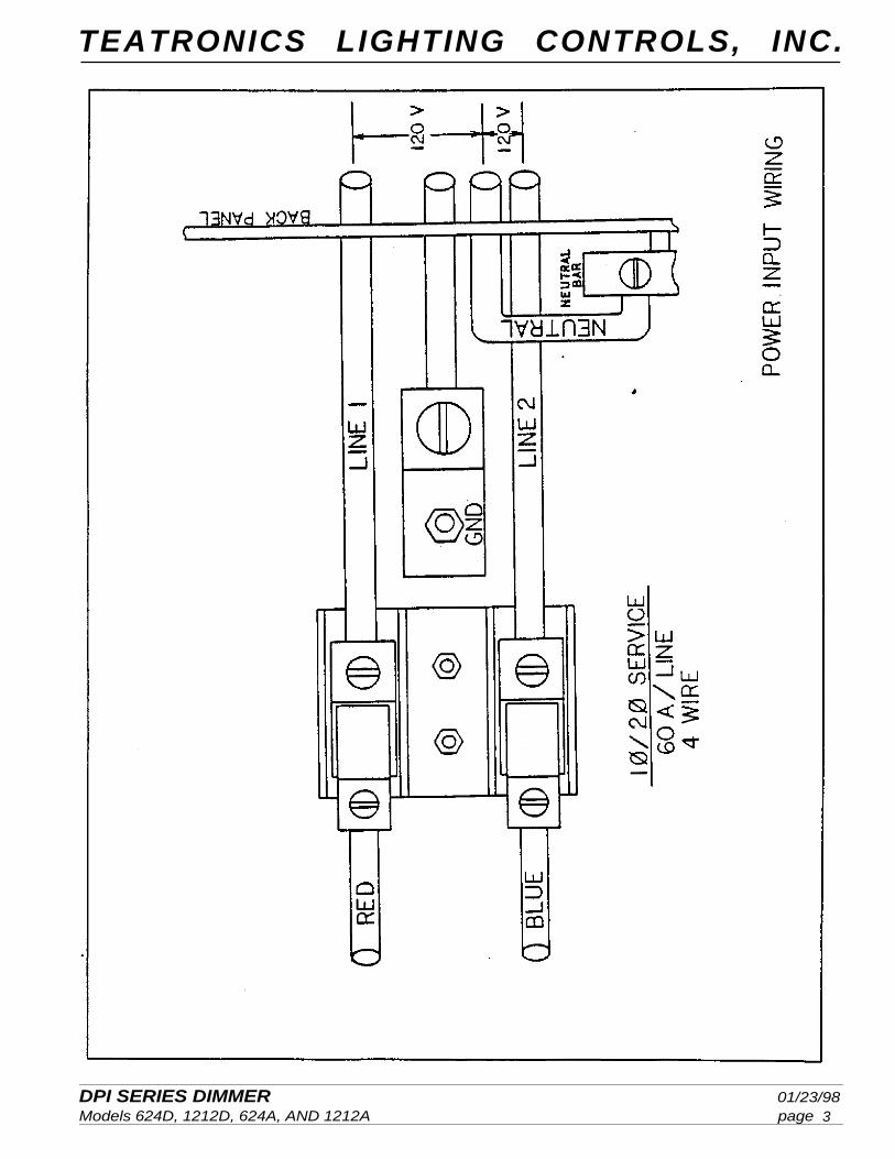
POWER HOOKUP
DPI SERIES DIMMER 01/23/98Models 624D, 1212D, 624A, AND 1212A page
TEATRONICS LIGHTING CONTROLS, INC.
3
DPI SERIES DIMMER 01/23/98Models 624D, 1212D, 624A, AND 1212A page
TEATRONICS LIGHTING CONTROLS, INC.
4
SETUP AND CONNECTION (continued)
ELECTRICAL INSTALLATION (continued)
POWER HOOKUP (continued)
DPI SERIES DIMMER 01/23/98Models 624D, 1212D, 624A, AND 1212A page
TEATRONICS LIGHTING CONTROLS, INC.
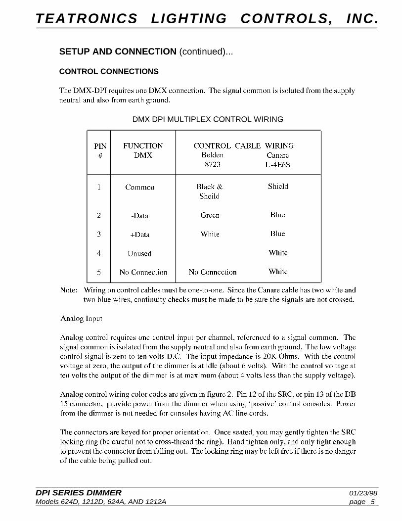
DMX DPI MULTIPLEX CONTROL WIRING
5
SETUP AND CONNECTION (continued)...
CONTROL CONNECTIONS
DPI SERIES DIMMER 01/23/98Models 624D, 1212D, 624A, AND 1212A page
TEATRONICS LIGHTING CONTROLS, INC.
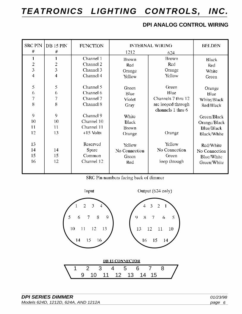
DPI ANALOG CONTROL WIRING
1 2 3 4 5 6 7 89 10 11 12 13 14 15
6
DPI SERIES DIMMER 01/23/98Models 624D, 1212D, 624A, AND 1212A page
TEATRONICS LIGHTING CONTROLS, INC.
OPERATION
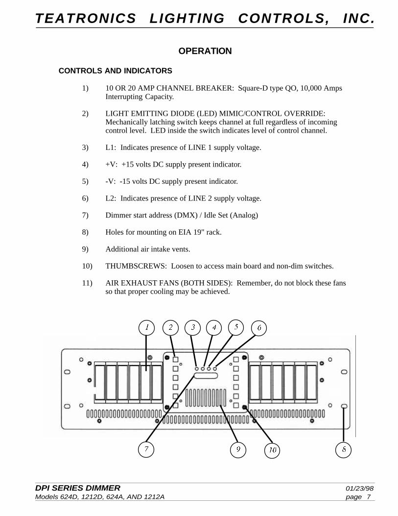
CONTROLS AND INDICATORS
1) 10 OR 20 AMP CHANNEL BREAKER: Square-D type QO, 10,000 AmpsInterrupting Capacity.
2) LIGHT EMITTING DIODE (LED) MIMIC/CONTROL OVERRIDE:Mechanically latching switch keeps channel at full regardless of incomingcontrol level. LED inside the switch indicates level of control channel.
3) L1: Indicates presence of LINE 1 supply voltage.
4) +V: +15 volts DC supply present indicator.
5) -V: -15 volts DC supply present indicator.
6) L2: Indicates presence of LINE 2 supply voltage.
7) Dimmer start address (DMX) / Idle Set (Analog)
8) Holes for mounting on EIA 19" rack.
9) Additional air intake vents.
10) THUMBSCREWS: Loosen to access main board and non-dim switches.
11) AIR EXHAUST FANS (BOTH SIDES): Remember, do not block these fansso that proper cooling may be achieved.
7
DPI SERIES DIMMER 01/23/98Models 624D, 1212D, 624A, AND 1212A page
TEATRONICS LIGHTING CONTROLS, INC.
8
OPERATION (continued)
CONTROL FUNCTIONS
Centered on the front panel are two columns of push-on/push-off switches. These ‘override’switches override any control signal coming to the dimmer and force the associated channel tofull. These switches are useful for testing, checking channel to load assignments, and focusing.They may also be used as a last ditch effort to get lights on stage if the console fails or thecontrol cable gets damaged. These switches should be left in the ‘out’ position for normaloperation.
Inside the override switches are status LED’s. These indicators mimic the control level for eachchannel. Pressing the override switch will also bring the control status LED to full. When asystem fails to operate properly, these indicators can help isolate the fault to either the controlor load side of the dimmer.
Each channel has an associated circuit breaker. The circuit breakers are provided for safety andto protect the load wiring. The breakers are not capable of protecting the internal dimmercomponents against short circuits, or extreme overloads. If the breaker trips after the load hasbeen up for a short period of time, it probably means that a slight overload exists. Hot patching,although it will not harm the dimmer, is not recommended by industry safety standards. If thebreaker trips immediately, it probably indicates an extreme overload or a shorted output. Miswiredfixtures, worn cables, loose connections or sloppy workmanship are all situations that can causecatastrophic failure. If, after the fault is cleared, the channel will not come up, will not go off,or stays part way on all the time, then the output device in the dimmer has failed.
NOTESince Teatronics Lighting Controls, Inc. has no control over customer installed wiring andfixtures, the solid-state relays are not covered under warranty. DPI dimmers are not shortcircuit proof.
DIMMER START ADDRESS
DPI SERIES DIMMER 01/23/98Models 624D, 1212D, 624A, AND 1212A page
TEATRONICS LIGHTING CONTROLS, INC.
9
OPERATION (continued)
CHANNEL LOADING
Any incandescent load from 40 Watts up to rated load capacity (1200 Watt for DPI 1212 and2400 Watts for DPI 624) may be connected to each dimmer channel. Although not U.L. listedfor other than incandescent loads, the DPI dimmer will not be harmed by most loads such asmotors, neons, pin-beam spots, fog machines, etc. ‘Dimming’ of these loads can sometimescause damage to the load however. Check with the manufacturer of the lighting instrument asto whether dimming is advisable on these loads. Teatronics Lighting Controls, Inc. recommendsde-rating the dimmer’s capacity by 30% when driving other than incandescent loads (840 Wattsmax. for DPI 1212 and 1680 Watts max. for DPI 624).
NON-DIM OPERATION
On the main control board in the DPI dimmer are slider switches. Each switch affects thedimmer’s channels(Groups of three DMX, Each Phase - Analog). In their normal ‘DIM’position, the associated channels function as an incandescent lamp dimmer with pre-heat idlevoltage. Some loads can be damaged by having an idle voltage applied or by applying less thanfull voltage to them. When the slide switch is placed in the ‘NON-DIM’ position, the associatedchannels function as solid-state switches which are either on or off, without any idle. Thechannels in non-dim mode will turn on with a control setting above 5 and will be off below 5.Flicker may be present if the control remains at, or near 5.
The non-dim switches on the main control board are accessed by loosening the four thumbscrews and removing the front cover plate. Located on the component side is switch 16, a fourposition DIP switch. Located near the DIP switch is nomenclature that indicates the correspondingchannels that each switch controls. Setting these DIP switches to the "ON" position will changethe corresponding channels to "non-dim".
Some loads, particularly strobe lights, will exhibit strange behavior when connected to a dimmer,even in non-dim mode. In the case of a strobe light, the small leakage current through the solid-state relay will cause the strobe to occasionally fire even when the relay is turned off. To curethis problem a small load (such as a 25 watt 120 volt lamp) should be placed in parallel with thestrobe light.
FILTERING
Each dimmer channel has an associated filter choke inside the pack. These chokes help to filterout the electrical noise that often causes hum in sound systems and musical instrument pick-ups. The chokes also help to eliminate ‘lamp sing’ that can cause audible noiseto come from the lighting fixtures. In providing these filtering functions, the chokes themselvesgenerate a slight buzz. It is recommended that the dimmer pack be placed in an area where thisbuzz will not be heard by the audience or picked up by recording equipment.
DPI SERIES DIMMER 01/23/98Models 624D, 1212D, 624A, AND 1212A page
TEATRONICS LIGHTING CONTROLS, INC.
10
OPERATION (continued)
OVERVOLTAGE PROTECTION
Line 1, nominally at 120 volts AC, provides power to the fan and power supply transformer.Should a miswiring condition occur such that the voltage between Line 1 and neutral exceeds140 volts AC, a sensing relay will disconnect the input to the fan and power supply thus protect-ing the dimmer from overvoltage. If the four green indicators on the front panel light onlymomentarily when power is applied, an overvoltage condition probably exists and must becorrected.
DPI SERIES DIMMER 01/23/98Models 624D, 1212D, 624A, AND 1212A page
TEATRONICS LIGHTING CONTROLS, INC.
IN CASE OF TROUBLE
TROUBLESHOOTING
This section serves two purposes. For the experienced user, it gives details that will help locatemost problems that are field serviceable. For the user who is not comfortable with live highvoltage circuits inches from their fingertips, this section will help locate suspected problemswith the dimmer and may save you a long distance phone call or shipping costs to a servicecenter (as well as down time). Even if the user is not able to solve the problem, performingthese diagnostics will help the user explain the malfunction to a service technician.
Please bear with us if we seem to state the obvious. Some of our customers are not as familiarwith dimming equipment and controls as others. Many apparent failures result from not beingfamiliar with the operating characteristics of the dimmer, so read the manual sections on "op-eration" carefully. The more experienced user may find the troubleshooting chart at the end ofthis manual more useful than this section.
In a system consisting of dimmers, control cables, and controllers, the first step is to confine themalfunction to one part of the system. Substituting known good parts, or swapping suspectedbad parts is an excellent trouble shooting technique. If disconnecting the dimmer from thecontrol wiring does not cure the problem then the control console is probably not at fault.
There are two forms of malfunction common to solid-state dimmers: “Failed Off” in which thelights do not come on, and “Failed On” in which the lights cannot be turned off.
If your system has “failed off”, check that a lamp load is connected and that the lamp is notburned out. Verify that the primary power is on and that all four LED’s on the front panel arelighted. Check that all channel breakers are on (in up position). A tripped breaker is reset byfirst turning the breaker to the fully off (down) position and then restoring it to its on (up)position. NOTE: Breakers often ‘trip’ when subjected to impact; check all breakers aftershipping or moving the dimmer pack. Make sure the loads are plugged in and that all extensioncords are continuous. Check load circuits by plugging them into a known live ‘non-dim’ circuitnot on the dimmer pack. Check that the control cable is intact, and plugged in at both ends.
Some consoles derive their operating power from the dimmer pack. If more than one dimmerpack is used with this type of console, the pack connected to the first few channels, suppliespower to the console. If the first pack is not powered or is disconnected from the console, noneof the channels will work.
The loads connected “failed on” dimmers will stay on until the channel breaker is turned off.First check that the channel override switches are turned off (out position). Try unplugging thecontrol cable from the dimmer. If the failure goes away, the cable or console is at fault. If theoutput stays on, then the problem is probably in the dimmer. For those who wish to attempt therepair themselves, consult the troubleshooting chart for more information. Be advised thatunauthorized repairs on units will void any remaining warranties.
11
DPI SERIES DIMMER 01/23/98Models 624D, 1212D, 624A, AND 1212A page
TEATRONICS LIGHTING CONTROLS, INC.
12
IN CASE OF TROUBLE (continued)
OBTAINING SERVICE
If after performing these tests you still cannot get proper operation, you may send your unit toT.L.C. Send your unit to the factory, freight prepaid, along with a note describing the specificcomplaint and the results of the checks you have made. Before shipping your equipment,please call the Sales Department to obtain a Return Materials Authorization number (RMAnumber). Our phone number is (805)528-6900. Please call during working hours, 8:30 to 4:30Pacific time. Send your unit well packed and insured to:
Teatronics Lighting Controls, Inc.1236 Los Osos Valley Rd., Ste. G
Los Osos, CA 93402ATTN: RMA #
DPI SERIES DIMMER 01/23/98Models 624D, 1212D, 624A, AND 1212A page
TEATRONICS LIGHTING CONTROLS, INC.
13
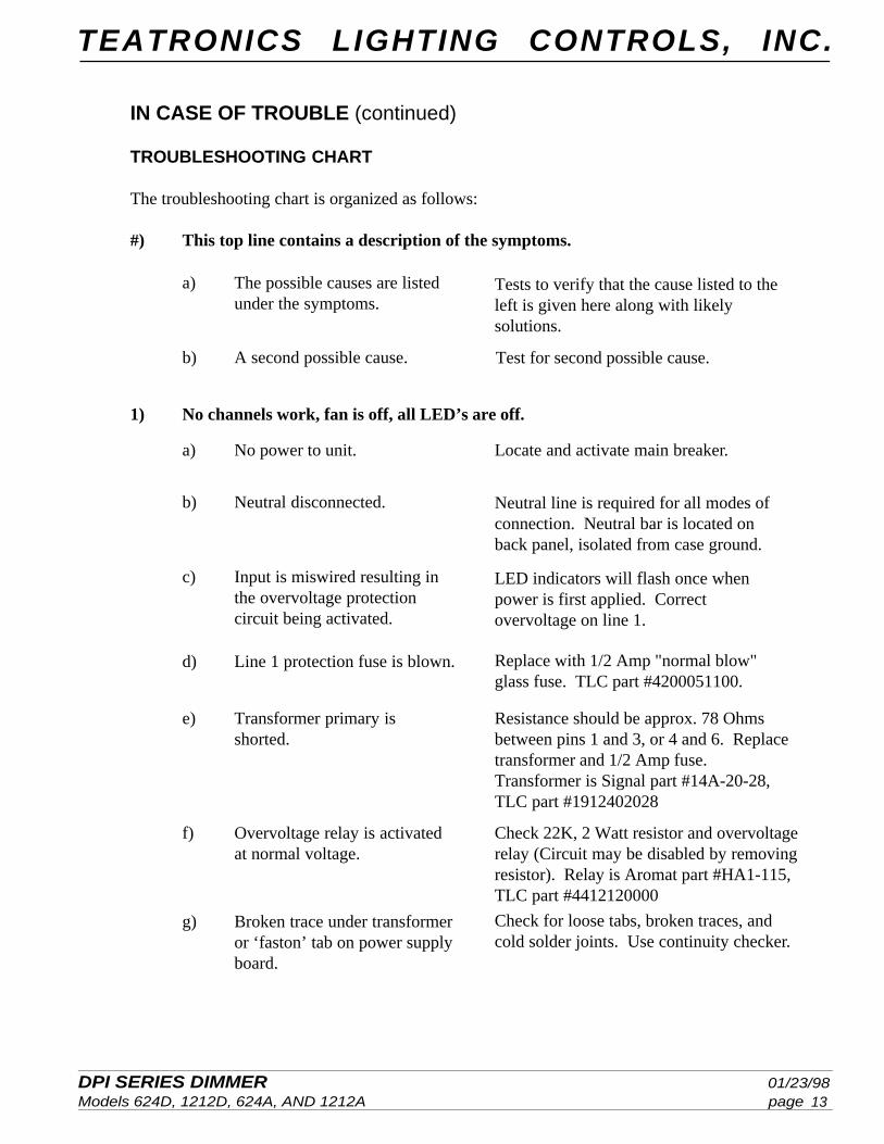
a) The possible causes are listedunder the symptoms.
Tests to verify that the cause listed to theleft is given here along with likelysolutions.
b) A second possible cause. Test for second possible cause.
1) No channels work, fan is off, all LED’s are off.
Neutral line is required for all modes ofconnection. Neutral bar is located onback panel, isolated from case ground.
c) Input is miswired resulting inthe overvoltage protectioncircuit being activated.
d) Line 1 protection fuse is blown.
e) Transformer primary isshorted.
f) Overvoltage relay is activatedat normal voltage.
LED indicators will flash once whenpower is first applied. Correctovervoltage on line 1.
Replace with 1/2 Amp "normal blow"glass fuse. TLC part #4200051100.
Resistance should be approx. 78 Ohmsbetween pins 1 and 3, or 4 and 6. Replacetransformer and 1/2 Amp fuse.Transformer is Signal part #14A-20-28,TLC part #1912402028
Check 22K, 2 Watt resistor and overvoltagerelay (Circuit may be disabled by removingresistor). Relay is Aromat part #HA1-115,TLC part #4412120000
Check for loose tabs, broken traces, andcold solder joints. Use continuity checker.
Locate and activate main breaker.a) No power to unit.
b) Neutral disconnected.
g) Broken trace under transformeror ‘faston’ tab on power supplyboard.
IN CASE OF TROUBLE (continued)
TROUBLESHOOTING CHART
The troubleshooting chart is organized as follows:
#) This top line contains a description of the symptoms.
DPI SERIES DIMMER 01/23/98Models 624D, 1212D, 624A, AND 1212A page
TEATRONICS LIGHTING CONTROLS, INC.
14
IN CASE OF TROUBLE (continued)
TROUBLESHOOTING CHART (continued)
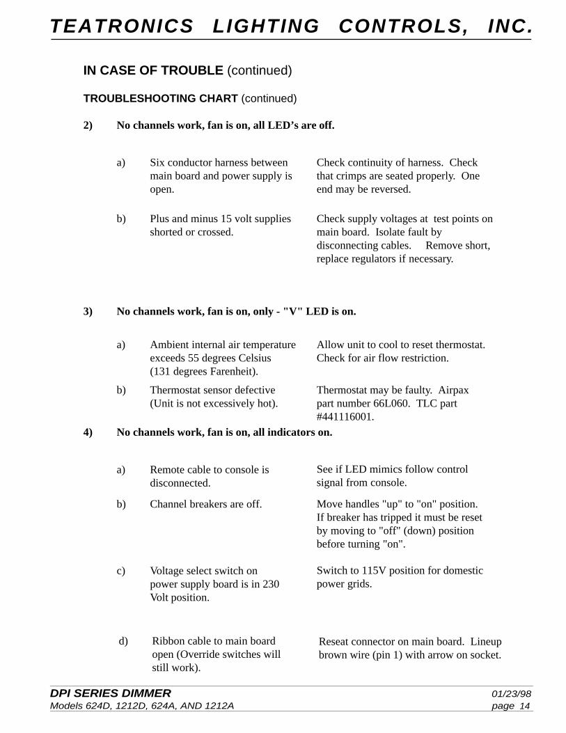
2) No channels work, fan is on, all LED’s are off.
b) Plus and minus 15 volt suppliesshorted or crossed.
b) Thermostat sensor defective(Unit is not excessively hot).
4) No channels work, fan is on, all indicators on.
b) Channel breakers are off.
c) Voltage select switch onpower supply board is in 230Volt position.
Check supply voltages at test points onmain board. Isolate fault bydisconnecting cables. Remove short,replace regulators if necessary.
3) No channels work, fan is on, only - "V" LED is on.
Allow unit to cool to reset thermostat.Check for air flow restriction.
Thermostat may be faulty. Airpaxpart number 66L060. TLC part#441116001.
See if LED mimics follow controlsignal from console.
Move handles "up" to "on" position.If breaker has tripped it must be resetby moving to "off" (down) positionbefore turning "on".
Switch to 115V position for domesticpower grids.
a) Ambient internal air temperatureexceeds 55 degrees Celsius(131 degrees Farenheit).
Check continuity of harness. Checkthat crimps are seated properly. Oneend may be reversed.
a) Remote cable to console isdisconnected.
a) Six conductor harness betweenmain board and power supply isopen.
d) Ribbon cable to main boardopen (Override switches willstill work).
Reseat connector on main board. Lineupbrown wire (pin 1) with arrow on socket.
DPI SERIES DIMMER 01/23/98Models 624D, 1212D, 624A, AND 1212A page
TEATRONICS LIGHTING CONTROLS, INC.
15
IN CASE OF TROUBLE (continued)
TROUBLESHOOTING CHART (continued)
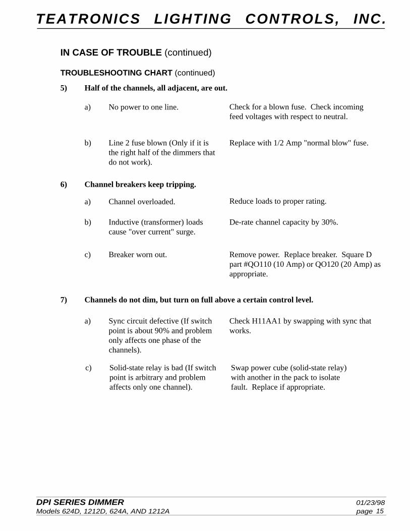
Check for a blown fuse. Check incomingfeed voltages with respect to neutral.
Replace with 1/2 Amp "normal blow" fuse.b) Line 2 fuse blown (Only if it isthe right half of the dimmers thatdo not work).
a) Channel overloaded. Reduce loads to proper rating.
c) Breaker worn out. Remove power. Replace breaker. Square Dpart #QO110 (10 Amp) or QO120 (20 Amp) asappropriate.
b) Inductive (transformer) loadscause "over current" surge.
De-rate channel capacity by 30%.
Check H11AA1 by swapping with sync thatworks.
a) No power to one line.
a) Sync circuit defective (If switchpoint is about 90% and problemonly affects one phase of the
channels).
6) Channel breakers keep tripping.
7) Channels do not dim, but turn on full above a certain control level.
5) Half of the channels, all adjacent, are out.
Swap power cube (solid-state relay)with another in the pack to isolatefault. Replace if appropriate.
c) Solid-state relay is bad (If switchpoint is arbitrary and problemaffects only one channel).
DPI SERIES DIMMER 01/23/98Models 624D, 1212D, 624A, AND 1212A page
TEATRONICS LIGHTING CONTROLS, INC.
16
IN CASE OF TROUBLE (continued)
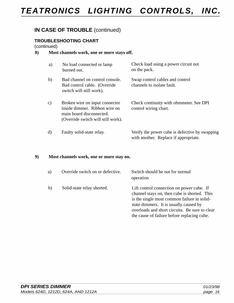
TROUBLESHOOTING CHART(continued)8) Most channels work, one or more stays off.
a) No load connected or lampburned out.
b) Bad channel on control console.Bad control cable. (Overrideswitch will still work).
c) Broken wire on input connectorinside dimmer. Ribbon wire onmain board disconnected.(Override switch will still work).
a) Override switch on or defective. Switch should be out for normaloperation
Swap control cables and controlchannels to isolate fault.
Check load using a power circuit noton the pack.
d) Faulty solid-state relay.
Check continuity with ohmmeter. See DPIcontrol wiring chart.
9) Most channels work, one or more stay on.
Verify the power cube is defective by swappingwith another. Replace if appropriate.
b) Solid-state relay shorted. Lift control connection on power cube. Ifchannel stays on, then cube is shorted. Thisis the single most common failure in solid-state dimmers. It is usually caused byoverloads and short circuits. Be sure to clearthe cause of failure before replacing cube.
DPI SERIES DIMMER 01/23/98Models 624D, 1212D, 624A, AND 1212A page
TEATRONICS LIGHTING CONTROLS, INC.
17
TROUBLESHOOTING CHART (continued)
IN CASE OF TROUBLE (continued)
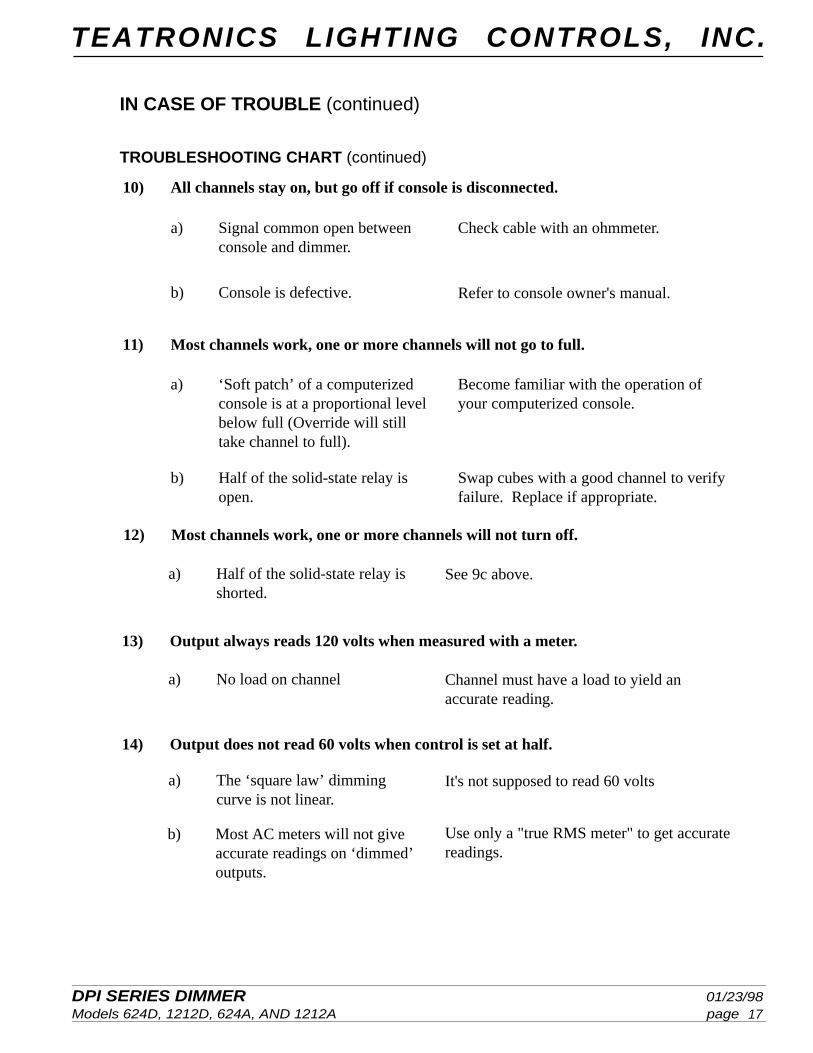
Swap cubes with a good channel to verifyfailure. Replace if appropriate.
10) All channels stay on, but go off if console is disconnected.
a) Signal common open betweenconsole and dimmer.
Check cable with an ohmmeter.
b) Console is defective. Refer to console owner's manual.
a) ‘Soft patch’ of a computerizedconsole is at a proportional levelbelow full (Override will stilltake channel to full).
Become familiar with the operation ofyour computerized console.
b) Half of the solid-state relay isopen.
11) Most channels work, one or more channels will not go to full.
13) Output always reads 120 volts when measured with a meter.
a) No load on channel
14) Output does not read 60 volts when control is set at half.
a) Half of the solid-state relay isshorted.
a) The ‘square law’ dimmingcurve is not linear.
See 9c above.
It's not supposed to read 60 volts
Channel must have a load to yield anaccurate reading.
Use only a "true RMS meter" to get accuratereadings.
12) Most channels work, one or more channels will not turn off.
b) Most AC meters will not giveaccurate readings on ‘dimmed’outputs.
DPI SERIES DIMMER 01/23/98Models 624D, 1212D, 624A, AND 1212A page
TEATRONICS LIGHTING CONTROLS, INC.
18
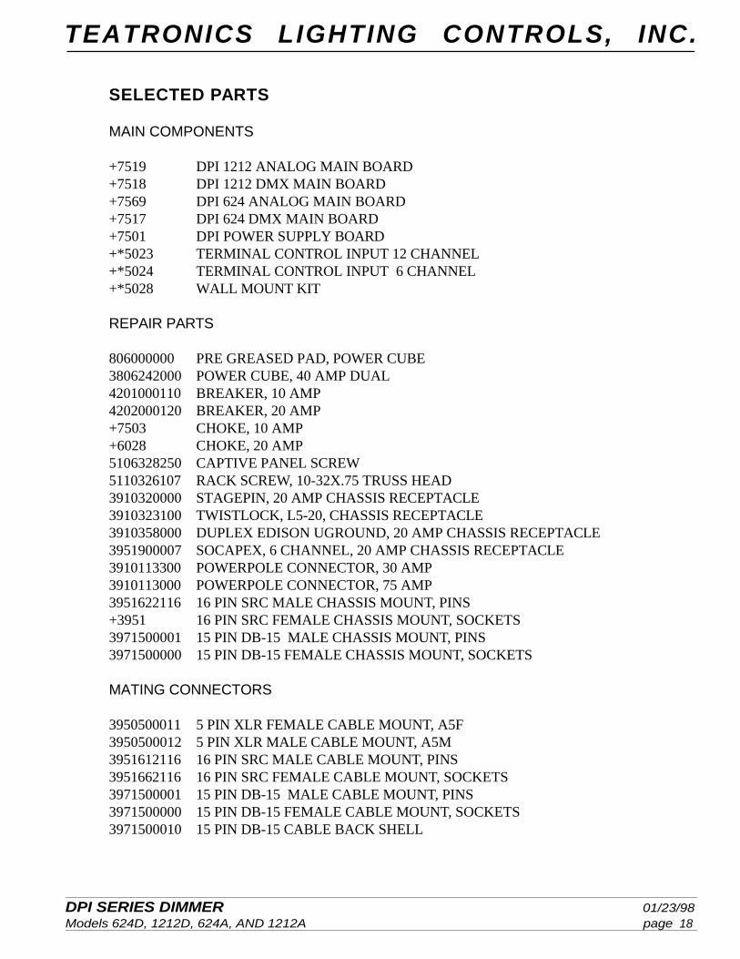
SELECTED PARTS
MAIN COMPONENTS
+7519 DPI 1212 ANALOG MAIN BOARD+7518 DPI 1212 DMX MAIN BOARD+7569 DPI 624 ANALOG MAIN BOARD+7517 DPI 624 DMX MAIN BOARD+7501 DPI POWER SUPPLY BOARD+*5023 TERMINAL CONTROL INPUT 12 CHANNEL+*5024 TERMINAL CONTROL INPUT 6 CHANNEL+*5028 WALL MOUNT KIT