Owner's Manual JCRnFTSMAN'I LAWN TRACTOR 17.5 HP, 42" Mower Electric Start Automatic Transmission Model No. 917.273180 i_ This product has a low emission engine which operates differently from previously built engines. Before you start the engine, read and understand this Owner's Manual. IMPORTANT: Read and follow all Safety Rules and Instructions before operating this equipment. For answers to your questions about this product, Call: 1-800-659-5917 Sears Craftsman Help Line 5 am - 5 pro, Mon - Sat Sears, Roebuck and Co., Hoffman Estates, IL 60179 U.S.A Visit our Craftsman website:www.sears.com/craftsman
i_ This product has a low emission engine which operatesdifferently from previously built engines. Before you start theengine, read and understand this Owner's Manual.
IMPORTANT:Read and follow all SafetyRules and Instructions before
operating this equipment.
For answers to your questions
about this product, Call:
1-800-659-5917Sears Craftsman Help Line5 am - 5 pro, Mon - Sat
Sears, Roebuck and Co., Hoffman Estates, IL 60179 U.S.AVisit our Craftsman website:www.sears.com/craftsman
Maintenance Schedule ........................ 18Service and Adjustments ..................... 22
Storage............................................Troubleshooting ................................Repair Parts ......................................... 34Sears Service ........................ Back Cover
LIMITED WARRANTY ON CRAFTSMAN RIDING EQUIPMENTFor two (2) years from the date of purchase, if this Craftsman Riding Equipment ismaintained, lubricated and tuned up according to the instructions in the owner's manual,Sears will repair or replace free of charge any parts that are found to be defective inmaterial or workmanship according to the guidelines of coverage listed below. Sears willalso provide free labor for these applicable warranted parts for the two full years. Duringthe first 30 days of purchase, there will be no charges to service the product at yourhome for issuescovered by thiswarranty.(See exclusions below). For your conve-nience IN HOME warrantyservice will stillbe available after the first 30 days of pur-chase but a tripcharge will apply.This charge willbe waived if the Craftsman productisdropped off at an authorized Sears location.For the nearest authorizedSears ocaton,please call 1-800-4-MY-HOME®. This warranty applies onlywhile thisproductis withinthe United States.
This Warranty does not cover:• Expendable items which become worn during normal use, including but not limited to
blades, spark plugs, air cleaners, belts, and oil filters.• Standard Maintenance Servicing, oil changes, or tune-ups.• Tire replacement or repair caused by punctures from outside objects, such as nails,
thorns, stumps, or glass.
i epairs necessarybecause of operator abuse, including but not limited to, damagecaused by towing objects beyond the capability of the riding equipment, impactingobjects that bend the frame or crankshaft, or over-speeding the engine.Repairs necessary because of operator negligence, including but not limited to, elec-trical and mechanical damage caused by improper storage, failure to use the propergrade and amount of engine oil, failure to keep the deck clear of flammable debris,or failure to maintain the equipment according to the instructions contained in theowner's manual.
• Engine (fuel system) cleaning or repairs caused by fuel determined to be contami-nated or oxidized (stale). In general, fuel should be used within 30 days of its pur-chase date.
• Normal deterioration and wear of the exterior finishes, or product label replacement.• Riding equipment used for commercial or rental purposes.
LIMITED WARRANTY ON BATTERYFor ninety (90) days from date of purchase, if any battery included with this riding equip-ment proves defective in material or workmanship and our testing determines the batterywill not hold a charge, Sears will replace the battery at no charge. During the first 30days of purchase, there will be no charges to replace the battery at yourHOME. Afterthe first 30 days, for your convenience,iN-HOME warranty service will still be avail-able but a trip charge will apply. This charge will be waived if the Craftsman product isdropped off at an authorized Sears location. For the nearest authorized Sears location,please call 1-800-4-MY-HOME®.
This battery warranty applies only while this product is within the United States.
This warranty gives you specific legal rights, and you may also have other rights, whichvary, from state to state.
Sears, Roebuck and Co.,Dept.817WA, Hoffman Estates, IL 60179
2
IMPORTANT: This cutting machine is capable of amputating hands and feet and throw-!ng objects. Failure to observe the following safety instructions could result in seriousmjury or death.
&WARNING: In order to prevent ac-
cidental starting when setting up, trans-porting, adjusting or making repairs,always disconnect spark plug wire andplace wire where it cannot contact sparkplug.
_I_WARNING: Do not coast down a
hill in neutral, you may lose control of thetractor.
_,WARNING: Tow only the attachmentsthat are recommended by and comply withspecifications of the manufacturer of yourtractor. Use common sense when towing.Operate only at the lowest possible speedwhen on a slope. Too heavy of a load,while on a slope, is dangerous. Tires canlose traction with the ground and causeyou to lose control of your tractor.
_,WARNING: Engine exhaust, someof its constituents, and certain vehiclecomponents contain or emit chemicalsknown to the State of California to causecancer and birth defects or other reproduc-tive harm.A
_I_WARNING: Battery posts, terminalsand related accessories contain lead andlead compounds, chemicals known to theState of California to cause cancer and
birth defects or other reproductive harm.Wash hands after handling.
I. GENERAL OPERATION
• Read, understand, and follow all instruc-tions in the manual and on the machinebefore starting.
• Only allow responsible adults, who arefamiliar with the instructions, to operatethe machine.
• Clear the area of objects such as rocks,toys, wire, etc., which could be pickedup and thrown by the blade.
• Be sure the area is clear of other peoplebefore mowing. Stop machine if anyoneenters the area.
• Never carry passengers.
• Do not mow in reverse unless abso-lutely necessary. Always look down andbehind before and while backing.
• Be aware of the mower discharge direc-tion and do not point it at anyone. Donot operate the mower without eitherthe entire grass catcher or the guard inplace.
• Slow down before turning.• Never leave a running machine unat-
tended. Always turn off blades, setparking brake, stop engine, and removekeys before dismounting.
• Turn off blades when not mowing.• Stop engine before removing grass
catcher or unclogging chute.• Mow only in daylight or good artificial
light.• Do not operate the machine while under
the influence of alcohol or drugs.• Watch for traffic when operating near or
crossing roadways.• Use extra care when loading or un-
loading the machine into a trailer ortruck.
• Data indicates that operators, age 60years and above, are involved in a largepercentage of riding mower-related in-juries. These operators should evaluatetheir ability to operate the riding mowersafely enough to protect themselvesand others from serious injury.
• Keep machine free of grass, leaves orother debris build-up which can touchhot exhaust / engine parts and burn. Donot allow the mower deck to plow leavesor other debris which can cause build-up to occur. Clean any oil or fuelspillage before operating or storing themachine. Allow machine to cool beforestorage.
II. SLOPE OPERATION
Slopes are a major factor related to loss-of-control and tipover accidents, which canresult in severe injury or death. All slopesrequire extra caution. If you cannot backup the slope or if you feel uneasy on it, donot mow it.
3
DO:
• Mow up and down slopes, not across.• Remove obstacles such as rocks, tree
limbs, etc.• Watch for holes, ruts, or bumps. Un-
even terrain could overturn the machine.Tall grass can hide obstacles.
• Use slow speed. Choose a low gearso that you will not have to stop or shiftwhile on the slope.
• Follow the manufacturer's recommend-ations for wheel weights or counter-weights to improve stability.
• Use extra care with grass catchers orother attachments. These can changethe stability of the machine.
• Keep all movement on the slopes slowand graduaL Do not make suddenchanges in speed or direction.
• Avoid starting or stopping on a slope.if tires lose traction, disengage theblades and proceed slowly straightdown the slope.
DO NOT:
• Do not turn on slopes unless neces-sary, and then, turn slowly and graduallydownhill, if possible.
• Do notmow near drop-offs, ditches,or embankments. The mower could
suddenly turn over if a wheel is overthe ed.ge of a cliff or ditch, or if an edgecaves in.
• Do not mow on wet grass. Reducedtraction could cause sliding.
• Do not try to stabilize the machine byputting your foot on the ground.
• Do not use grass catcher on steepslopes.
III. CHILDREN
Tragic accidents can occur if the operatoris not alert to the presence of children.Children are often attracted to the ma-chine and the mowing activity. Neveras-sume that children will remain where youlast saw them.• Keep children out of the mowing area
and under the watchful care of anotherresponsible adult.
• Be alert and turn machine off if childrenenter the area.
• Before and when backing, look behindand down for small children.
• Never carry children. They may fall offand be seriously injured or interfere withsafe machine operation.
• Never allow children to operate themachine.
• Use extra care when approaching blindcorners, shrubs, trees, or other objectsthat may obscure vision.
IV. SERVICE
• Use extra care in handling gasoline andother fuels. They are flammable andvapors are explosive.- Use only an approved container.- Never remove gas cap or add fuel
with the engine running. Allowengine to cool before refueling. Donot smoke.
- Never refuel the machine indoors.- Never store the machine or fuelcontainer inside where there is anopen flame, such as a water heater.
• Never run a machine inside a closedarea.
• Keep nuts and bolts, especially bladeattachment bolts, tight and keep equip-ment in good condition.
• Never tamper with safety devices.Check their proper operation regularly.
• Keep machine free of grass, leaves, orother debris build-up. Clean oil or fuelspillage. Allow machine to cool beforestoring.
• Stop and inspect the equipment if youstrike an object. Repair, if necessary,before restarting.
• Never make adjustments or repairs withthe engine running.
• Grass catcher components are subjectto wear, damage, and deterioration,which could expose moving parts orallow objects to be thrown. Frequentlycheck components and replace withmanufacturer's recommended parts,when necessary.
• Mower blades are sharp and can cut.Wrap the blade(s) or wear gloves, anduse extra caution when servicing them.
• Check brake operation frequently. Ad-just and service as required.
4
• Be sure the area is clear of other peoplebefore mowing. Stop machine if anyoneenters the area.
• Never carry passengers or childreneven with the blades off.
• Do not mow in reverse unless abso-lutely necessary. Always look down andbehind before and while backing.
• Never carry children. They may fall offand be seriously injured or interfere withsafe machine operation.
• Keep children out of the mowing areaand under the watchful care of anotherresponsible adult.
• Be alert and turn machine off if childrenenter the area.
• Before and when backing, look behindand down for small children.
• Mow up and down slopes (15 ° Max), notacross.
• Remove obstacles such as rocks, treelimbs, etc.
• Watch for bores, ruts, or bumps. Uneventerrain could overturn the machine. Tall
grass can hide obstacles.• Use slow speed. Choose a low gear
so that you will not have to stop or shiftwhile on the slope.
• Avoid starting or stopping on a slope. Iftires lose traction, disengage the bladesand proceed slowly straight down theslope.
• If machine stops while going uphill,disengage blades, shift into reverse andback down slowly.
• Do not turn on slopes unless necessary,and then, turn slowly and graduallydownhill, if possible.
CONGRATULATIONS on your purchaseof a new tractor. It has been designed,engineered and manufactured to giveyou the best possible dependability andperformance.Should you experience any problem youcannot easily remedy, please contact aSears or other qualified service center.We have competent, well-trained techni-cians and the proper tools to service orrepair this tractor.Please read and retain this manual. Theinstructions will enable you to assembleand maintain your tractor properly. Alwaysobserve the "SAFETY RULES".
CUSTOMER RESPONSIBILITIES
• Read and observe the safety rules.• Follow a regular schedule in main-
taining, caring for and using your tractor.• Follow the instructions under "Mainte-
nance" and "Storage" sections of thisowner's manual.
_WARNING: This tractor is equippedwith an internal combustion engine andshould not be used on or near any unim-proved forest-covered, brush-covered orgrass-covered land unless the engine'sexhaust system is equipped with a sparkarraster meeting applicable local or statelaws (if any). If a spark arrester is used, itshould be maintained in effective workingorder by the operator.
In the state of California the above is re-
quired by law (Section 4442 of the Califor-nia Public Resources Code). Other statesmay have similar laws. Federal laws applyon federal lands. A spark arrester for themuffler is available through your nearestSears service center (See REPAIR PARTSsection of this manual).
REPAIR PROTECTIONAGREEMENTS
Congratulations on making a smart pur-chase. Your new Craftsman® product isdesigned and manufactured for years ofdependable operation, But like all prod-ucts, it may require repair from time totime. That's when having a Repair Protec-tion Agreement can save you money andaggravation.Purchase a Repair Protection Agreementnow and protect yourself from unexpectedhassle and expense.Here's what's included in the Agreement:• Expert service by our 12,000 profe-
sional repair specialists.• Unlimited service and no charge for
parts and labor on all covered repairs.• Product replacement if your covered
product can't be fixed.• Discount of 10% from regular price of
service and service-related parts notcovered by the agreement; also, 10%off regular price of preventive mainte-nance check.
• Fast help by phone- phone supportfrom a Sears technician on productsrequiring in-home repair, plus conve-nient repair scheduling.
Once you purchase the Agreement, asimple phone call is all that it takes for youto schedule service. You can call anytimeday or night, or schedule a service ap-pointment online.Sears has over 12,000 professional repairspecialists, who have access to over 4.5million quality parts and accessories.That's the kind of professionalism you cancount on to help prolong the life of yournew purchase for years to come. Purchaseyour Repair Protection Agreement today!Some limitations and exclusions apply.For prices and additional informationcall 1-800-827-6655.
SEARS INSTALLATION SERVICEFor Sears professiona/ insta//ationof homeappliances, garage door openers, waterheaters, and other major home items, inthe U.S.A. call 1-800-4-MY-HOME®
6
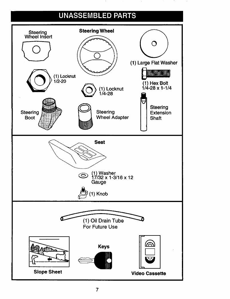
SteeringWheel Insert
SteeringBoot
(1) Locknut1/2-20
Steering Wheel
(1) Locknut1/4-28
SteeringWheel Adapter
(1) Large Flat Washer
(1) Hex Bolt1/4-28 x 1-1/4
SteeringExtensionShaft
(1) Washer17/32 x 1-3/16 x 12Gauge
_i_ (1) Knob
(_1_(1) Oil Drain_
For Future Use
Slope Sheet
Keys
Video Cassette
7
Your new tractor has been assembled at the factory with the exception of those parts leftunassembled for shipping purposes. To ensure safe and proper operation of your tractorall parts and hardware you assemble must be tightened securely. Use the correct toolsas necessary to insure proper tightness. Review the video cassette before you begin.
TOOLS REQUIRED FORASSEMBLYA socket wrench set will make assemblyeasier, Standard wrench sizes are listed.(1) 3/4" wrench Pliers(2) 7/16" wrenches Utility knifeTire pressure gauge
When right or left hand is mentioned inthis manual, it means when you are mthe operating position (seated behind thesteering wheel).
TO REMOVE TRACTOR FROMCARTONUNPACK CARTON
1. Remove all accessible loose parts andparts boxes from carton.
2. Cut along dotted lines on all four pan-els of carton. Remove end panels andlay side panels flat.
3. Check for any additional loose parts orcartons and remove.
BEFORE REMOVING TRACTORFROM SKIDATTACH STEERING WHEEL
ASSEMBLE EXTENSION SHAFT ANDBOOT
1. Slide extension shaft onto lower steer-ing shaft. Align mounting holes in ex-tension and lower shafts and install 1/4hex bolt and Iocknut. Tighten securely.
IMPORTANT" Tighten bolt and nut se-curely to 10-12 ft. Ibs torque.2. Place tabs of steering boot over tab
slots in dash and push down to secure.
INSTALL STEERING WHEEL3. Position front wheels of the tractor so
they are pointing straight forward.4. Remove steering wheel adapter from
steering wheel and slide adapter ontosteering shaft extension•
5. Position steering wheel so cross barsare horizontal (left to right) and slideinside boot and onto adapter.
6. Assemble large flat washer, 1/2 hexnut and tighten securely.
_._ Insert
_1/2 Rex NutLarge FlatWasher
Steering/@ eering Boot
Wheel_Tabs
Adapter---------_
_/Extension Shaft
1/4 Locknut---_...._ 1
_'_1/4 Hex Bolt
Lower _ _ "_--" "-• I
Steenng _ . '_Shaff----_""_l\ • _/ ' ,'
- - - -, F lau",.. -. _ Slots
7, Snap steering wheel insert into centerof steering wheel.
8, Remove protective materials from trac-tor hood and grill.
IMPORTANT: Check for and remove anystaples in skid that may puncture tireswhere tractor is to roll off skid.
HOW TO SET UP YOUR TRACTORINSTALL SEAT
Adjust seat before tightening adjustmentknob.
1. Remove adjustment knob and flatwasher securing seat to cardboardpacking and set aside for assembly ofseat to tractor.
2. Pivot seat upward and remove fromthe cardboard packing. Remove thecardboard packing and discard.
8
3. Place seat on seat pan so head ofshoulder bolts are positioned over thelarge slotted holes in pan.
4. Push down on seat to engage shoul-der bolts in slots and pull seat towardsrear of tractor.
5. Pivot seat and pan forward and as-semble adjustment knob and flatwasher loosely. Do not tighten.
6. Lower seat into operating position andsit in seat.
7. Slide seat until a comfortable positionis reached which allows you to pressclutch/brake pedal all the way down.
8. Get off seat without moving its ad-justed position.
9. Raise seat and tighten adjustmentknob securely.
Seat
Seat Pan
ShoulderBolts
FlatWasher
Adjl
CHECK BATTERY
1. Lift seat pan to raised position.NOTE: If this battery is put into serviceafter month and year indicated on label(label located between terminals) chargebattery for minimum of one hour at 6-10amps. (See "BATTERY" in Maintenancesection of this manual for charging instruc-tions).
erminal
NOTE: You may now roll or drive yourtractor off the skid. Follow the appropriateinstruction below to remove the tractorfrom the skid.
TO ROLL TRACTOR OFF SKID (SeeOperation section for location and
function of controls)1. Press lift lever plunger and raise
attachment lift lever to its highest po-sition.
2. Release parking brake by depressingclutch/brake pedal.
3. Place freewheel control in "trans-mission disengaged" position (See "TOTRANSPORT" in the Operation sectionof this manual).
4. Roll tractor forward off skid.5. Remove banding holding deflector
shield up against tractor.
TO DRIVETRACTOR OFF SKID (SeeOperation section for location andfunction of controls)_WARNING: Before starting, read, un-derstand and follow all instructions in theOperation section of this manual. Be suretractor is in a well-ventilated area. Be surethe area in front of tractor is clear of otherpeople and objects.1. Be sure all the above assembly steps
have been completed.2. Check engine oil level and fill fuel tank
with gasoline.3. Place freewheel control in "trans-
mission engaged" position. (See =TOTRANSPORT" in the Operation sectionof this manual).
4. Sit on seat in operating position,depress clutch/brake pedal and set theparking brake.
5. Place motion control lever in neutral(N) position.
6. Press lift lever plunger and raiseattachment lift lever to its highest posi-tion.
7. Start the engine. After engine hasstarted, move throttle control to idleposition.
8. Release parking brake.9. Slowly move the motion control lever
forward and slowly drive tractor offskid.
10.Apply brake to stop tractor, set parkingbrake and place motion control lever inneutral position.
11 .Turn ignition key to "STOP" position.Continue with the instructions that follow.
9
INSTALL MULCHER PLATE
(If previously removed)1. Raise and hold deflector shield in
upright position.2. Place front of mulcher plate over front
of mower deck opening and slide intoplace, as shown.
3. Hook front latch into hole on front ofmower deck.
4. Hook rear latch into hole on back ofmower deck.
DeflectorShield
MulcherPlate
LatchHooks
_k CAUTION: Do not remove deflectorshield from mower.TO CONVERTTO BAGGING ORDISCHARGINGSimply remove mulcher plate and store ina safe place. Your mower is now ready fordischarging or installation of optional grasscatcher accessory.NOTE: It is not necessary to changeblades. The mulching blades are designedfor discharging and bagging also.
CHECKTIRE PRESSURE
The tires on your tractor were overinflatedat the factory for shipping purposes. Cor-rect tire pressure is important for bestcutting performance.• Reduce tire pressure to PSI shown in
"PRODUCT SPECIFICATIONS" sectionof this manual.
CHECK DECK LEVELNESSFor best cutting results, mower hous-ing should be properly leveled. See "TOLEVEL MOWER HOUSING" in the Serviceand Adjustments section of this manual.
CHECK FOR PROPER POSITIONOF ALL BELTS
See the figures that are shown for replac-ing motion and mower blade drive beltsin the Service and Adjustments sectionof this manual. Verify that the belts arerouted correctly.
CHECK BRAKE SYSTEM
After you learn howto operate yourtrac-tor, check to see that the brake is properlyadjusted. See "TO ADJUST BRAKE" inthe Service and Adjustmentssectionofthismanual.
o/CHECKLISTBefore you operate your new tractor, wewish to assure that you receive the bestperformance and satisfaction from thisquality product.Please review the following checklist:•/ All assembly instructions have been
completed.,/No remaining loose parts in carton.4 Battery is properly prepared and
charged. (Minimum 1 hour at 6 amps)./ Seat is adjusted comfortably and tight-
ened securely.,/All tires are properly inflated. (For ship-
ping purposes, the tires were overin-flated at the factory).
,/Be sure mower deck is properly leveledside-to-side/front-to-rear for best cuttingresults. (Tires must be properly inflatedfor leveling).
,/Check mower and drive belts. Be surethey are routed properly around pulleysand inside all belt keepers.
,/Check wiring. See that all connectionsare still secure and wires are properlyclamped.
,/Before driving tractor, be sure freewheelcontrol is in "transmission engaged"position (see "TO TRANSPORT" in theOperation section of this manual).
While learning how to use your tractor, payextra attention to the following importantitems:,/Engine oil is at proper level.,/Fuel tank is filled with fresh, clean,
regular unleaded gasoline.,/Become familiar with all controls - their
location and function. Operate thembefore you start the engine.
,/Be sure brake system is in safe oper-ating condition.
/ It is important to purge the transmissionbefore operating your tractor for the firsttime. Follow proper starting and trans-mission purging instructions (See 'q'OSTART ENGINE" and "PURGE TRANS-MISSION" in the Operation section ofthis manual).
10
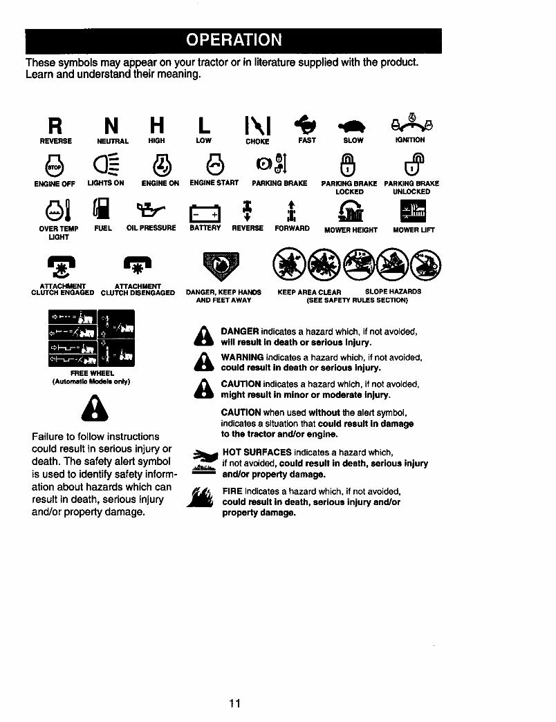
These symbols may appearon your tractor or in literaturesupplied with the product.Learn and understandtheir meaning.
R N H L I\1REVERSE NEUTRAL HIGH LOW CHOKE FAST SLOW IGNITION
ENGINE OFF LIGHTS ON ENGINE ON ENGINE START PARKING BRAKE PARKING BRAKE PARKING BRAKELOCKED UNLOCKED
could result in serious injury ordeath. The safety alert symbolis used to identify safety inform-ation about hazards which can
result in death, serious injury J_and/or property damage.
DANGER indicatesa hazard which, if not avoided,will result in death or serious Injury.
WARNING indicates a hazard which, if not avoided,could result in death or serious injury.
CAUTION indicates a hazard which, if not avoided,might result in minor or moderate injury.
CAUTION when used without the alert symbol,indicatesa situation that could result in damageto the tractor and/or engine.
HOT SURFACES indicatesa hazard which,if not avoided, could result in death, serious injuryand/or property damage.
FIRE indicatesa hazard which, if not avoided,could result in death, serious injury and/orproperty damage.
11
KNOW YOUR TRACTORREADTHIS OWNER'S MANUAL AND SAFETY RULES BEFORE OPERATINGYOURTRACTORCompare the illustrations with your tractor to familiarize yourseff with the locations ofvarious controls and adjustments. Save this manual for future reference.
Ammeter
Throttle/ChokeControl
AttachmentClutch Lever
Ignition SwitchLight Switch
Lift Lever
J Plunger
AttachmentLift Lever
Clutch/BrakePedal
HeightAdjustmentIndicator
FreewheelControl Parking Brake Lever
MotionControlLever
Our tractors conform to the safety standards of theAmerican National Standards Institute.
AMMETER - Indicates charging (+) ordischarging (°) of battery.ATTACHMENT CLUTCH LEVER - Usedto engage the mower blades, or other at-tachments mounted to your tractor.ATTACHMENT LIFT LEVER - Used toraise, lower, and adjust the mower deck orother attachments mounted to your tractor.CLUTCH/BRAKE PEDAL - Used fordeclutching and braking the tractor andstarting the engine.MOTION CONTROL LEVER - Selects thespeed and direction of tractor.
IGNITION SWITCH - Used for starting andstopping the engine.LIFT LEVER PLUNGER - Used to releaseattachment lift lever when changing itsposition.LIGHT SWITCH POSITION - Turns theheadlights on and off.PARKING BRAKE LEVER - Locks clutch/brake pedal into the brake position.THROTTLE/CHOKE CONTROL - Usedfor starting and controlling engine speed.FREEWHEEL CONTROL - Disengagagestransmission for pushing or slowly towingthe tractor with the engine off.
12
The operation of any tractor can result in foreign objects thrown into theeyes, which can result in severe eye damage. Always wear safety glasses Ior eye shields while operating your tractor or performing any adjustments Ior repairs. We recommend standard safety glasses or a wide vision safety Imask worn over spectacles. I
HOW TO USE YOUR TRACTORTO SET PARKING BRAKE
Your tractor is equipped with an operatorpresence sensing switch. When engineis running, any attempt by the operatorto leave the seat without first setting theparking brake will shut off the engine.1. Depress clutch/brake pedal all the way
down and hold.2. Pull parking brake lever up and release
pressure from clutch/brake pedal.Pedal should remain in brake position.Make sure parking brake will hold trac-tor secure.
Throttle/Choke
Control
"Brake" Attachment ClutchPosition Lever "Engaged"
Key"Disengaged"
BrakePedal Parking Brake
Position
"Disengaged" Position Control Lever
STOPPING
MOWER BLADES -
• To stop mower blades, move attach-ment clutch lever to disengaged posi-tion.
GROUND DRIVE -
• To stop ground drive, depress clutch/brake pedal all the way down.
• Move motion control lever to neutral (N)position.
IMPORTANT: The motion control lever
does not return to neutral (N) positionwhen the clutch/brake pedal is depressed.
ENGINE -• Move throttle control between half and
full speed (fast) position.NOTE: Failure to move throttle controlbetween half and full speed (fast) posi-tion, before stopping, may cause engineto "backfire".• Turn ignition key to "STOP" position and
remove key. Always remove key whenleaving tractor to prevent unauthorizeduse.
• Never use choke to stop engine.
IMPORTANT: Leaving the ignition switchin any position other than "STOP" willcause the battery to discharge and godead.NOTE: Under certain conditions whentractor is standing idle with the enginerunning, hot engine exhaust gases maycause "browning" of grass. To eliminatethis possibility, always stop engine whenstopping tractor on grass areas.
_J_CAUTION: Always stop tractor com-pletely, as described above, before leavingthe operator's position.
TO USETHROTTLE CONTROL
Always operate engine at full throttle.• Operating engine at less than full
throttle reduces the battery chargingrate.
• Full throttle offers the best bagging andmower performance.
13
TO MOVE FORWARD AND BACKWARD
The direction and speed of movement iscontrolled by the motion control lever.1. Start tractor with motion control lever in
neutral (N) position.2, Release parking brake,3. Slowly move motion control lever to
desired position.
TO ADJUST MOWER CU'I-rlNG HEIGHT
The position of the attachment lift leverdetermines the cutting height.• Grasp lift lever.• Press plunger with thumb and move
lever to desired position.The cutting height range is approxi-mately 1-1/2 to 4". The heights are mea-sured from the ground to the blade tip withthe engine not running. These heightsare approximate and may vary dependingupon soil conditions, height of grass andtypes of grass being mowed.• The average lawn should be cut to ap-
proximately 2-1/2 inches during the coolseason and to over 3 inches during hotmonths. For healthier and better look-ing lawns, mow often and after moder-ate growth.
• For best cutting performance, grassover 6 inches in height should bemowed twice. Make the first cut rela-tively high; the second to desired height.
TO ADJUST GAUGEWHEELS
Gauge wheels are properly adjustedwhen they are slightly off the ground whenmower is at the desired cutting height inoperating position. Gauge wheels thenke'ep the-deck ,n proper pos'tion to helpprevent scalping in most terrain conditions.NOTE: Adjust gauge wheels with tractoron a flat level surface.I. Adjust mower to desired cutting height
(See "TO ADJUST MOWER CUTTINGHEIGHT" in this section of manual).
2. With mower in desired height of cutposition, gauge wheels should beassembled so they are slightly off theground. Install gauge wheel in ap-propriate hole with shoulder bolt, 3/8washer, and 3/8-1 6 Iocknut and tightensecurely.
3. Repeat for opposite side, installinggauge wheel in same adjustment hole.
Your tractor is equipped with an operatorpresence sensing switch. Any attemptby the operator to leave the seat with theengine running and the attachment clutchengaged will shut off the engine. You mustremain fully and centrally positioned in theseat to prevent the engine from hesitatingor cutting off when operating your equip-ment on rough, rolling terrain or hills.1. Select desired height of cut.2. Start mower blades by engaging at-
_uLCAUTION: Do not operate the mowerwithout either the entire grass catcher,on mowers so equipped, or the deflectorshield in place.
Attachment Attachemnt
=Engaged" HighPosition _? Position
Position
Position Deflector
TO OPERATE ON HILLS_kWARNING: Do not drive up or downhills with slopes greater than 15° and donot drive across any slope. Use the slopeguide at the back of this manual.• Choose the slowest speed before start-
ing up or down hills.• Avoid stopping or changing speed on
hills.• If slowing is necessary, move throttle
control lever to slower position.• If stopping is absolutely necessary, push
clutch/brake pedal quickly to brake posi-tion and engage parking brake.
• Move motion control lever to neutral (N)position.
IMPORTANT: The motion control leverdoes not return to neutral (N) positionwhen the clutch/brake pedal is depressed.• To restart movement, slowly release
parking brake and clutch/brake pedal.• Slowly move motion control lever to
slowest setting.• Make all turns slowly.
TO TRANSPORT
When pushing or towing your tractor, besure to disengage transmission by placingfreewheel control in freewheeling position.Freewheel control is located at the reardrawbar of tractor.1. Raise attachment lift to highest position
with attachment lift control.2. Pull freewheel control out and down
into the slot and release so it is held inthe disengaged position.
• Do not push or tow tractor at more thantwo (2) MPH.
• To re-engage transmission, reverseabove procedure.
14
Transmlsslon Engaged
Transmission Disengaged
NOTE: To protect hood from damagewhen transporting your tractor on a truckor a trailer, be sure hood is closed andsecured to tractor. Use an appropriatemeans of tying hood to tractor (rope, cord,etc.).
TOWING CARTS AND OTHER ATTACH-MENTS
Tow onlythe attachmentsthat are recom-mended by and complywith specificationsof the manufacturerof yourtractor.Usecommon sense when towing.Too heavyof a load, while on a slope, is dangerous.Tires can lose tractionwith the groundandcause you to lose control of yourtractor.BEFORE STARTING THE ENGINECHECK ENGINE OIL LEVEL
The engine in your tractor has beenshipped, from the factory, already filledwith summer weight oil.1. Check engine oil with tractor on level
ground.2. Unthraad and remove oil fill cap/
dipstick; wipe oil off. Reinsert the dip-stick into the tube and rest oil fill cap onthe tube. Do not thread the cap ontothe tube. Remove and read oil level. Ifnecessary, add oil until "FULL" markon dipstick is reached. Do not overfill.
• For cold weather operation you shouldchange oil for easier starting (See the oilviscosity chart in the Maintenance sec-tion of this manual).
• To change engine oil, see the Mainte-nance section in this manual.
ADD GASOLINE• Fill fuel tank to bottom of tank filler neck.
Do not overfill. Use fresh, clean, regularunleaded gasoline with a minimum of 87octane. (Use of leaded gasoline will in-crease carbon and lead oxide depositsand reduce valve life). Do not mix oilwith gasoline. Purchase fuel in quanti-ties that can be used within 30 days toassure fuel freshness.
CAUTION: Wipe off any spilled oil orfuel. Do not store, spill or use gasolinenear an open flame.IMPORTANT: When operating in tempera-tures below 32°F(0°C), use fresh, cleanwinter grade gasoline to help insure goodcold weather starting.CAUTION: Alcoholblended fuels (calledgasohol or using ethanol or methanol) canattract moisture which leads to separa-tion and formation of acids during storage.Acidic gas can damage the fuel system ofan engine while in storage.To avoid engine problems, the fuel systemshould be emptied before storage of 30days or longer. Drain the gas tank, startthe engine and let it run until the fuel linesand carburetor are empty.Use fresh fuel next season. See StorageInstructions for additional information.Never use engine or carburetor cleanerproducts in the fuel tank or permanentdamage may occur.
TO START ENGINE
When starting the engine for the first timeor if the engine has run out of fuel, it willtake extra cranking time to move fuel fromthe tank to the engine.1. Be sure freewheel control is in the
transmission engaged position.2, Sit on seat in operating position,
depress clutch/brake pedal and setparking brake.
3. Place motion control lever in neutral(N) position.
4. Move attachment clutch to disengagedposition.
5. Move throttle control to choke position.NOTE: Before starting, read the warmand cold starting procedures below.6. Insert key into ignition and turn key
clockwise to start position and releasekey as soon as engine starts. Donot run starter continuously for morethan fifteen seconds per minute. If theengine does not start after severalattempts, move throttle control to fastposition, wait a few minutes and tryagain. If engine still does not start,move the throttle control back to thechoke position and retry.
15
WARM WEATHER STARTING (50 ° F andabove)
7. When engine starts, move the throttlecontrol to the fast position.
• The attachments and ground drive cannow be used. If the engine does notaccept the load, restart the engine andallow it to warm up for one minute usingthe choke as described above.
COLD WEATHER STARTING ( 50 ° F andbelow)
7. When engine starts, allow engineto run with the throttle control in the
choke position until the engine runsroughly, then move throttle controlto fast position. This may require anengine warm-up period from severalseconds to several minutes, dependingon the temperature.
AUTOMATIC TRANSMISSION WARM UP
Before driving the unit in cold weather,the transmission should be warmed up asfollows:1. Be sure the tractor is on level ground.2. Place the motion control lever in
neutral. Release the parking brakeand let the clutch/brake slowly returnto operating position.
3. Allow one minute for transmission towarm up.This can be done duringthe engine warm up period.
• The attachments can also be used dur-ing the engine warm-up period after thetransmission has been warmed up.
NOTE: If at a high altitude (above 3000feet) or in cold temperatures (below 32 F)the carburetor fuel mixture may need tobe adjusted for best engine performance.(See "TO ADJUST CARBURETOR" in theService and Adjustments section of thismanual.)
PURGE TRANSMISSIONCAUTION: Never engage or dis-
engage freewheel lever while the engineis running.To ensure proper operation and per-formance, it is recommended that thetransmission be purged before operatingtractor for the first time. This procedure willremove any trapped air inside the trans-mission which may have developed duringshipping of your tractor.IMPORTANT: Should your transmissionrequire removal for service or replace-ment, it should be purged after reinstall-ation before operating the tractor.1. Place tractor safely on level surface
with engine off and parking brake set.2. Disengage transmission by placing
freewheel control in "transmission dis-engaged" position (See =TO TRANS-PORT" in this section of manual).
3. Sitting in the tractor seat, start engine.After the engine is running, movethrottle control to slow position. Withmotion control lever in neutral (N)position, slowly disengage clutch/brakepedal.
4. Move motion control lever to fullforward position and hold for five (5)seconds. Move lever to full reverseposition and hold for five (5) seconds.Repeat this procedure three (3) times.
NOTE: During this step there will be nomovement of drive wheels. The air is beingremoved from hydraulic drive system.5. Move motion control lever to neutral
(N) position. Shutoff engine and setparking brake.
6. Engage transmission by placingfreewheel control in "transmissionengaged" position (See 'riO TRANS-PORT' in this section of manual).
7. Sitting in the tractor seat, start engine.After the engine is running, movethrottle control to half (1/2) speed.With motion control lever in neutral (N)position, slowly disengage clutch/brakepedal.
8. Slowly move motion control lever for-ward, after the tractor moves approxi-mately five (5) feet, slowly move motioncontrol lever to reverse position. Afterthe tractor moves approximately five(5) feet return the motion control leverto the neutral (N) position. Repeat thisprocedure with the motion control leverthree (3) times.
Your transmission is now purged andready for normal operation.
16
MOWING TIPS• Mower should be properly leveled for
best mowing performance. See "TOLEVEL MOWER HOUSING" in theService and Adjustments section of thismanual.
• The left hand side of mower should beused for trimming.
• Drive so that clippings are dischargedonto the area that has already been cut.Have the cut area to the right of the trac-tor. This will result in a more even distri-bution of clippings and more uniformcutting.
• When mowing large areas, start byturning to the right so that clippings willdischarge away from shrubs, fences,driveways, etc. After one or two rounds,mow in the opposite direction makingleft hand turns until finished.
f
1t
.Ip
II
J• If grass is extremely tall, it should be
mowed twice to reduce load and pos-sible fire hazard from dried clippings.Make first cut relatively high; the secondto the desired height.
• Do not mow grass when it is wet.Wet grass will plug mower and leaveundesirable clumps. Allow grass to drybefore mowing.
• Always operate engine at full throttlewhen mowing to assure better mow-ing performance and proper dischargeof material. Regulate ground speed byselecting a low enough gear to give themower cutting performance as well asthe quality of cut desired.
• When operating attachments, select aground speed that will suit the terrainand give best perform_,nce of the at-tachment being used.
MULCHING MOWING TIPSIMPORTANT: Forbest performance,keepmower housingfree of built-upgrass andtrash. Clean after each use,• The special mulchingblade will recut
the grass clippings many times andreduce them in size so that as they fallonto the lawn they will disperse intothe grass and not be noticed. Also, themulched grass will biodegrade quicklyto provide nutrients for the lawn. Alwaysmulch with your highest engine (blade)speed as this will provide the best recut-ting action of the blades,Avoid cutting your lawn when it is wet,Wet grass tends to form clumps andinterferes with the mulching action. Thebest time to mow your lawn is the earlyafternoon. At this time the grass hasdried, the newly cut area will not beexposed to direct sunlight.For best results, adjust the mowercutting height so that the mower cutsoff only the top one-third of the grassblades. For extremely heavy grass, re-duce your width of cut on each pass andmow slowly.
• Certain types of grass and grassconditions may require that an area bemulched a second time to completelyhide the clippings. When doing a sec-ond cut, mow across (perpendicular) tothe first cut path.
• Change your cutting pattern from weekto week. Mow north to south one weekthen change to east to west the nextweek. This will help prevent matting andgraining of the lawn.
17
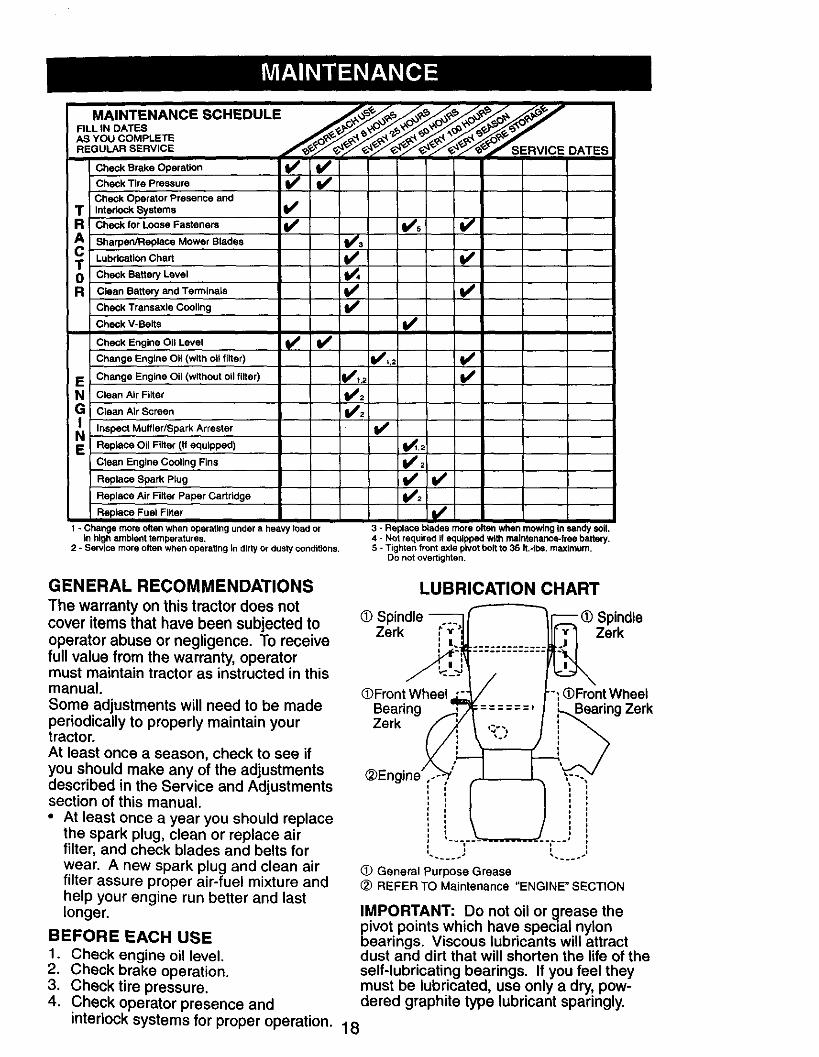
MAINTENANCE SCHEDULE _ ,_. _ ,_. _o_ ,_ ,_
AS YOU COMPLETE _ ._e _._q_ _> _, _ _
REGULAR SERVICE DATES
Check Brake Operation _Check Tire Pressure
Check Operator Presence andT InterlockSystems t_
R Check for Loose Fasteners _ l_s I_
A Sharpec/Replace Mower Blades _a
T Lubrication Chart
0 Check Battery LevelR Clean Battery and Terminals I_
Check Transaxle Cooling I_
Check V-Belts I_'
Check Engine Oil Level tf V'
Change Engine 011 (with OHfilter) I_,;
E Change Engine Oil (without oil filter) I_IR,/
N Clean Air Filter
G Clean Air Screen
Inspect Muffler/Spark Arrester
E Replace Oil Filter (if equipped) 1_,2
Clean Engine Cooling Fins _ 2
Replace Spark Plug _ l# #
Replace Air Filter Paper Cartridge
Replace Fuel Filter if #
1 - Change more often when operating under a heavy load orin high ambient temperatures.
2 - Service more often when operating in dirty or dusty condittens,
3 - Replace blades more often when mowing In sandy soil.4 - Not required if equipped with maintenance-free battery.5 - Tighten front axle pivot bolt to 35 It.-Ibe. maximum.
Do not overtighten.
GENERAL RECOMMENDATIONSThe warranty on this tractor does notcover items that have been subjected tooperator abuse or negligence. To receivefull value from the warranty, operatormust maintain tractor as instructed in thismanual.Some adjustments will need to be madeperiodically to properly maintain yourtractor.At least once a season, check to see ifyou should make any of the adjustmentsdescribed in the Service and Adjustmentssection of this manual.• At least once a year you should replace
the spark plug, clean or replace airfilter, and check blades and belts forwear. A new spark plug and clean airfilter assure proper air-fuel mixture andhelp your engine run better and lastlonger.
LUBRICATION CHART
(D Spindle -- _) SpindleZerk Zerk
O)Front Wheel -_ (DFront WheelBearing ZerkZerk
(!) General Purpose Grease(2) REFER TO Maintenance "ENGINE" SECTION
BEFORE EACH USEt. Check engine oil level.2. Check brake operation.3. Check tire pressure.4. Check operator presence and dered graphite type lubricant sparingly.
interlock systems for proper operation. 18
IMPORTANT: Do not oil or grease thepivot points which have special nylonbearings. Viscous lubricants will attractdust and dirt that will shorten the life of theself-lubricating bearings. If you feel theymust be lubricated, use only a dry, pow-
TRACTORAlways observe safety rules when per-forming any maintenance.BRAKE OPERATIONIf tractor requires more than six (6) feetstopping distance at high speed in highestgear, then brake must be adjusted. (See"TO ADJUST BRAKE" in the Service andAdjustments section of this manual).TIRES• Maintain proper air pressure in all tires
(See =PRODUCT SPECIFICATIONS"section of this manual).
• Keep tires free of gasoline, oil, or insectcontrol chemicals which can harm rub-bar.
• Avoid stumps, stones, deep ruts, sharpobjects and other hazards that maycause tire damage.
NOTE: To seal tire punctures and preventflat tires due to slow leaks, tire sealantmay be purchased from your local partsdealer. Tire sealant also prevents tire dryrot and corrosion.OPERATOR PRESENCE SYSTEMBe sure operator presence and interlocksystems are working properly. If your trac-tor does not function as described, repairthe problem immediately.• The engine should not start unless
the brake pedal is fully depressed andattachement clutch control is in thedisengaged position.
• When the engine is running, any at-tempt by the operator to leave the seatwithout first setting the parking brakeshould shut off the engine.
• When the engine is running and theattachment clutch is engaged, any at-tempt by the operator to leave the seatshould shut off the engine.
• The attachment clutch should never op-erate unless the operator is in the seat.
BLADE CAREFor best results mower blades must bekept sharp. Replace bent or damagedblades.
BLADE REMOVAL1. Raise mower to highest position to al-
low access to blades.2. Remove blade belt, lock washer and
flat washer securing blade.3. Install new or resharpened blade
with trailing edge up towards deck asshown.
IMPORTANT: To ensure proper assembly,center hole in blade must align with staron mandrel assembly.
4. Reassemble blade bolt, lock washerand flat washer in exact order asshown.
IMPORTANT: Blade bolt is heat treated. Ifbolt needs replacing, replace only with ap-prove bolt shown in the Repair Parts.
Blade CenterEdge Up Hole
MandrelAssembly
Lock WasherBlade Bolt
TO SHARPEN BLADE
NOTE: We do not recommend sharp-ening blade - but if you do, be sure theblade is balanced.Care should be taken to keep the bladebalanced. An unbalanced blade will cause
excessive vibration and eventual damageto mower and engine.• The blade can be sharpened with a file
or on a grinding wheel. Do not attemptto sharpen while on the mower.
• To check blade balance, you will need a5/8" diameter steel bolt, pin, or a conebalancer. (When using a cone balancer,follow the instructions supplied withbalancer.)
NOTE: Do not use a nail for balancingblade. The lobes of the center hole mayappear to be centered, but are not.• Slide blade on to an unthreaded portion
of the steel bolt or pin and hold thebolt or pin parallel with the ground. Ifblade is balanced, it should remain in ahorizontal position. If either end of theblade moves downward, sharpen theheavy end until the blade is balanced.
Blade5/8" Bolt
Center t
BATTERY
Your tractor has a battery charging systemwhich is sufficient for normal use. How-ever, periodic charging of the battery withan automotive charger will extend its life.• Keep battery and terminals clean.• Keep battery bolts tight.• Keep small vent holes open.• Recharge at 6-10 amperes for I hour.
19
NOTE: The original equipment battery onyour tractor is maintenance free. Do notattempt to open or remove caps or covers.Adding or checking level of electrolyte isnot necessary.TO CLEAN BATTERY AND TERMINALSCorrosion and dirt on the battery andterminals can cause the battery to =leak"power.1. Disconnect BLACK battery cable first
then RED battery cable and removebattery from tractor.
2. Rinse the battery with plain water anddry.
3. Clean terminals and battery cable endswith wire brush until bright.
4. Coat terminals with grease or petro-leum jelly.
5. Reinstall battery (See =REPLACINGBATTERY" in the Service and Adjust-ments section of this manual).
TRANSAXLE COOLING
The transmission fan and cooling finsshould be kept clean to assure propercooling.Do not attempt to clean fan or transmis-sion while engine is running or while thetransmission is hot. To prevent possibledamage to seals, do not use high pressurewater or steam to clean transaxle.• Inspect cooling fan to be sure fan blades
are intact and clean.• Inspect cooling fins for dirt, grass clip-
pings and other materials. To preventdamage to seals, do not use com-pressed air or high pressure sprayer toclean cooling fins.
TRANSAXLE PUMP FLUIDThe transaxle was sealed at the factoryand fluid maintenance is not required forthe life of the transaxle. Should the trans-axle ever leak or require servicing, contacta Sears or other qualified service center.
V-BELTSCheck V-belts for deterioration and wearafter 100 hours of operation and replaceif necessary. The belts are not adjustable.Replace belts if they begin to slip fromwear.
ENGINELUBRICATION
Only use high quality detergent oil ratedwith API service classification SG-SL.Select the oil's SAE viscosity gradeaccording to your expected operatingtemperature.
Change the oil after every 50 hours of op-eration or at least once a year if the tractoris not used for 50 hours in one year.Check the crankcase oil level before start-ing the engine and after each eight (8)hours of operation.
ITO CHANGE ENGINE OIL
Determine temperature range expectedbefore oil change. All oil must meet APIservice classification SG-SL• Be sure tractor is on level surface.• Oil will drain more freely when warm.• Catch oil in a suitable container.1. Remove oil fill cap/dipstick. Be careful
not to allow dirt to enter the enginewhen changing oil.
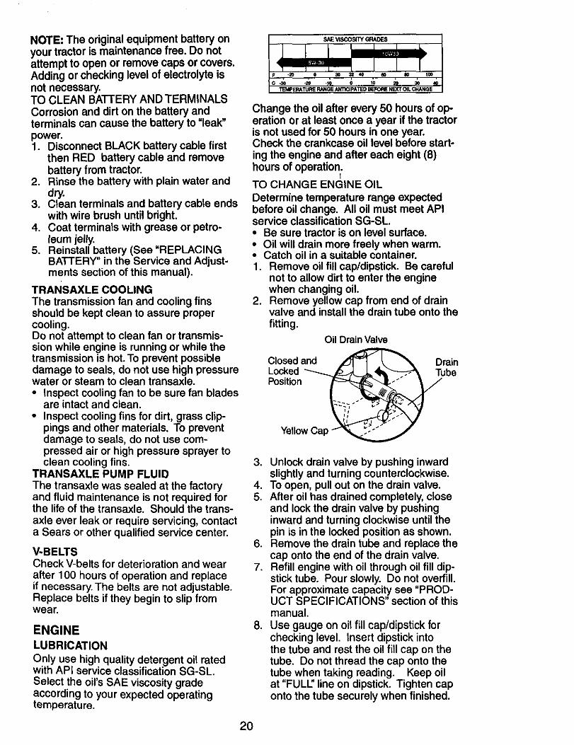
2. Remove yellow cap from end of drainvalve and install the drain tube onto thefitting.
Oil DrainValve
Closed and ,_.L_ DrainLocked _ _li .'_- Tube
Position_
Yellow Cap
3. Unlock drain valve by pushing inwardslightly and turning counterclockwise.
4. To open, pull out on the drain valve.5. After oil has drained completely, close
and lock the drain valve by pushinginward and turning clockwise until thepin is in the locked position as shown.
6. Remove the drain tube and replace thecap onto the end of the drain valve.
7. Refill engine with oil through oil fill dip-stick tube. Pour slowly. Do not overfill.For approximate capacity see "PROD-UCT SPECIFICATIONS" section of thismanual.
8. Use gauge on oil fill cap/dipstick forchecking level. Insert dipstick intothe tube and rest the oil fill cap on thetube. Do not thread the cap onto thetube when taking reading. Keep oilat "FULL" line on dipstick. Tighten caponto the tube securely when finished.
20
AIR FILTERYourengine will not run properlyusing adirty air filter. Clean the foam pre-cleanerafter every 25 hoursof operation or everyseason. Service paper cartridge every100 hoursof operation or every season,whicheveroccurs first.Service air cleaner more often underdustyconditions.1. Remove knob and cover.2. Remove wing nut and air cleaner from
base.
TO SERVICE PRE-CLEANER
3. Slide foam pre-cleaner off cartridge.4. Wash it in liquid detergent and water.5. Squeeze it dry in a clean cloth. Allow it
to dry.6. Saturate it in engine oil. Wrap it in
clean, absorbent cloth and squeeze toremove excess oil.
TO SERVICE CARTRIDGE
1. Replace a dirty, bent, or damagedcartridge.
NOTE: Do not wash the paper cartridgeor use pressurized air, as this will damagethe cartridge.2. Reinstall the pre-cleaner (cleaned and
oiled) over the paper cartridge.3. Reassemble air cleaner, wing nut,
cover and tighten knob securely.
Air CleanerCover _ Knob
NutFoam \Pre- \ RubberCleaner Grommet
Screen
PaperCartridge
Air CleanerBase
Fill Cap/Dipstick
ENGINE OIL FILTER
Replace the engine oil filter every seasonor every other oil change if the tractor isused more than 100 hours in one year.CLEAN AIR SCREEN
Air screen must be kept free of dirt andchaff to prevent engine damage fromoverheating, Clean with a wire brush orcompressed air to remove dirt and stub-born dried gum fibers, 21
CLEAN AIR INTAKE/COOLING AREAS
To insure proper cooling, make sure thegrass screen, cooling fins, and other exter-nal surfaces of the engine are kept clean atall times.Every 100 hours of operation (more oftenunder extremely dusty, dirty conditions),remove the blower housing and othercooling shrouds. Clean the cooling fins andexternal surfaces as necessary. Make surethe cooling shrouds are reinstalled.NOTE: Operating the engine with ablocked grass screen, dirty or pluggedcooling fins, and/or cooling shrouds re-moved will cause engine damage due tooverheating.MUFFLER
Inspect and replace corroded muffler andspark arrester (if equipped) as it could cre-ate a fire hazard and/or damage.SPARK PLUG(S)
Replace spark plug(s) at the beginning ofeach mowing season or after every 100hours of operation, whichever occurs first.Spark plug type and gap setting are shownin "PRODUCT SPECIFICATIONS" sectionof this manual.
IN-LINE FUEL FILTER
The fuel filter should be replaced onceeach season. If fuel filter becomesclogged, obstructing fuel flow to carbu-retor, replacement is required.1. With engine cool, remove filter and
plug fuel line sections.2. Place new fuel filter in position in fuel
line with arrow pointing towards carbu-retor.
3. Be sure there are no fuel line leaks andclamps are properly positioned.
4. Immediately wipe up any spilled gaso-line.
Clamp
Fuel FilterCLEANING
• Clean engine, battery,seat, finish, etc. of allforeign matter.
• Keep finished surfaces and wheels free of allgasoline, oil, etc.
• Protect painted surfaceswithautomotivetype wax.
We do not recommendusinga garden hose orpressurewasher to clean your tractorunlessthe engine and transmissionare covered tokeep water out.Water in en.gineor transmis-sion willshorten the useful lifeof your tractor.Use compressedair or a leaf blowerto removegrass, leaves and trash from tractorandmower.
WARNING: TO AVOID SERIOUS INJURY, BEFORE PERFORMING ANY SER-VICE OR ADJUSTMENTS:1. Depress clutch/brake pedal fully and set parking brake.2. Place motion control lever in neutral (N) position.3. Place attachment clutch in =DISENGAGED" position.4. Turn ignition key to "STOP" and remove key.5. Make sure the blades and all moving parts have completely stopped.6. Disconnect spark plug wire from spark plug and place wire where it cannot
come in contact with plug.
TRACTOR
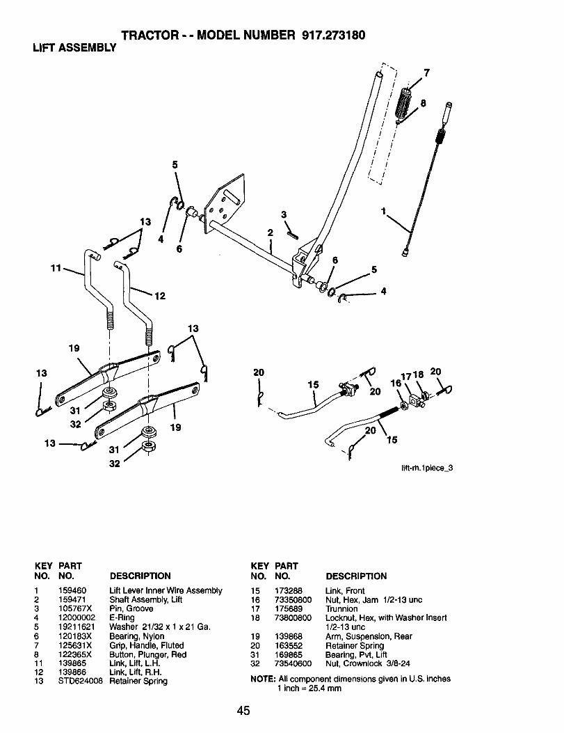
TO REMOVE MOWERMower will be easier to remove from theright side of tractor.1. Place attachment clutch in "DISEN-
GAG ED" position.2. Move attachment lift lever forward to
lower mower to its lowest position.3. Roll belt off engine pulley.4. Remove small retainer spring, and
remove clutch spring off pulley bolt.5. Remove large retainer spring, slide
collar off and push housing guide outof bracket.
6. Disconnect anti-sway bar from chassisbracket by removing retainer spring.
7. Disconnect suspension arms from reardeck brackets by removing retainersprings.
8. Disconnect front links from deck byremoving retainer springs.
9. Raise lift lever to raise suspensionarms. Slide mower out from under trac-tor.
Small Retainer Sprin
Clutch Spring
Small Retainer Sprin
Clutch Spring
IMPORTANT: If an attachment otherthan the mower deck is to be mountedon the tractor, remove the front links andhook the clutch spring Into square hole inframe.TO INSTALL MOWER
1, Raise attachment lift lever to its high-est position.
2, Slide mower under tractor with deflec-tor shield to right side of tractor.
3. Lower lift lever to its lowest position.4. Connect front links to mower deck and
secure with retainer springs.5. Connect suspension arms to rear
deck brackets and secure with retainer
springs.6. Connect anti-sway Dar to chassis
bracket and secure with retainerspring.
7. Push clutch cable housing guide intobracket, slide collar onto guide andsecure with large retainer spring.
8. Place flat washer and clutch spring onidler pulley bolt and secure with smallretainer spring.
9. Install belt onto engine pulley.
line Pulley
Retainer Sprin
Anti-Swa_
Collar ._.Retainer Springs(Both Sides)
Deflector Shield
Housing •LargeRetainerSpring Bracket
22
TO LEVEL MOWERHOUSINGAdjust the mower while tractor is parkedon level ground or driveway. Make suretires areproperly inflated (See "PROD-UCT SPECIFICATIONS" section of thismanual). If tires are over or underin-flated, you will not properly adjust yourmower.SIDE-TO-SIDE ADJUSTMENT• Raise mower to its highest position.• At the midpoint of both sides of mower,
measure height from bottom edge ofmower to ground. Distance "A" onboth sides of mower should be thesame or within 1/4" of each other.
• If adjustment is necessary, make ad-justment on one side of mower only.
• To raise one side of mower, tighten liftlink adjustment nut on that side.
• To lower one side of mower, loosen liftlink adjustment nut on that side.
NOTE: Each full turn of adjustment nutwill change mower height about 1/8".• Recheck measurements after adjusting.
Bottom edge Bottom edgeof mower to _ __of mower to
ground _ ground
A--_-TL'""_Ground Line _'""_
• When distance =D" is 1/8" to 1/2' lowerat front than rear, tighten nuts =F"againsttrunnion on both front links.
• To raise front of mower, loosen nut "F"from trunnion on both front links. Tightennut =E" on both front links an equalnumber of turns. The two front links mustremain equal in length.
• When distance =D" is 1/8" to 1/2" lowerat front than rear, tighten nut "F" againsttrunnion on both front links.
• Recheck side-to-side adjustment.
Mandrel
"D" "IY'
Both Front Links Should be Equal in Length
Nut =E"
_.j[.__ Arm
LiftLinkAdjustment Nut _ _ -
FRONT-TO-BACK ADJUSTMENTIMPORTANT: Deck must be level side-toside. If the following front-to-back adjust-ment is necessary, be sure to adjust bothfront links equally so mower will stay levelside-to-side.
To obtain the best cutting results, themower housing should be adjusted sothat the front is approximately 1/8" to 1/2"lower than the rear when the mower is inits highest position.Check adjustment on right side of tractor.Measure distance "D" directly in front andbehind the mandrel at bottom edge ofmower housing as shown.• Before making any necessary adjust-
ments, check that both front links areequal in length.
• If links are not equal in length, adjustone link to same length as other link.
• To lower front of mower loosen nut "E"on both front links an equal number ofturns.
Front Links
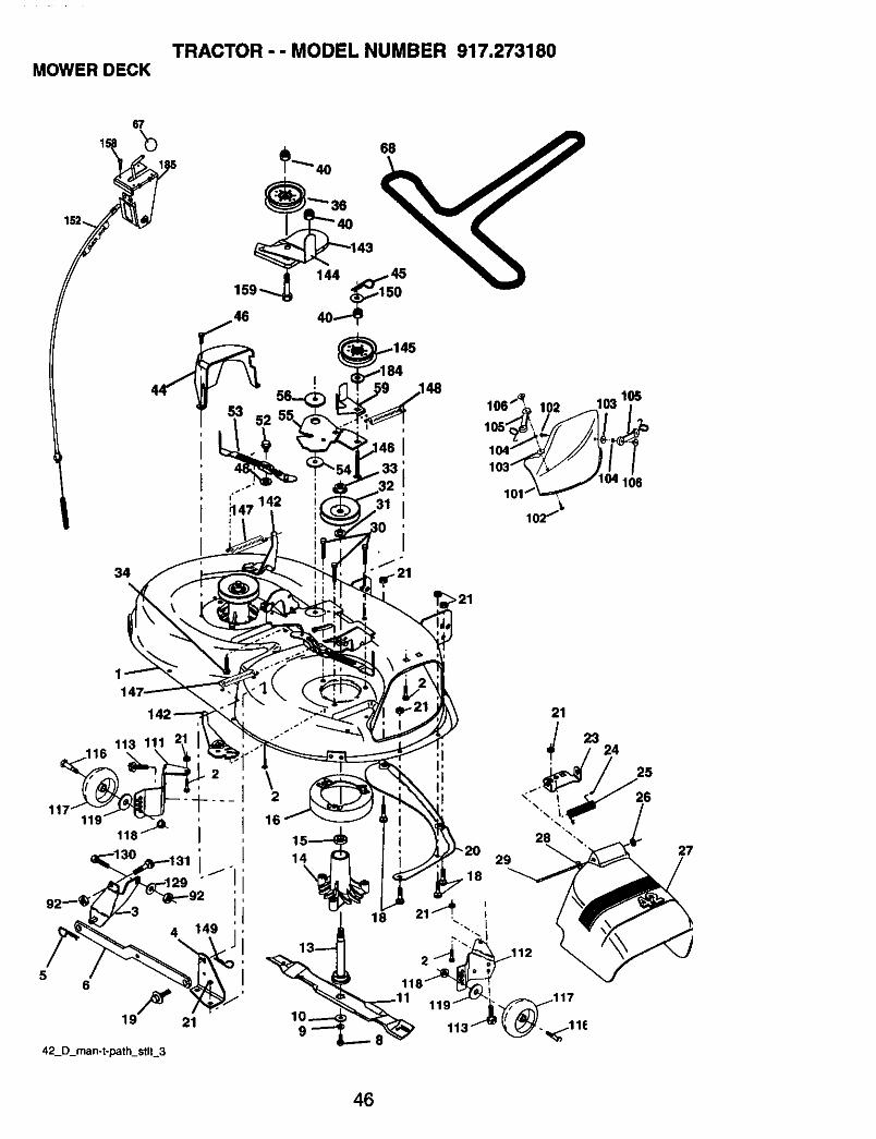
TO REPLACE MOWER BLADE DRIVEBELT
The mower blade drive belt may be re-placed without tools. Park the tractor onlevel surface. Engage parking brake.
BELT REMOVAL -
1. Remove mower from tractor (See '_OREMOVE MOWER" in this section ofmanual).
2. Work belt off both mandrel pulleys andidler pulleys.
3. Pull belt away from mower.
BELT INSTALLATION -
I. Work beltaround both mandrel pulleysand idlerpulleys
2. Make sure beltisinallpulleygroovesand insideallbeltguides.
3. Installmower (See =To InstallMower" inthissectionofthismanual).
23
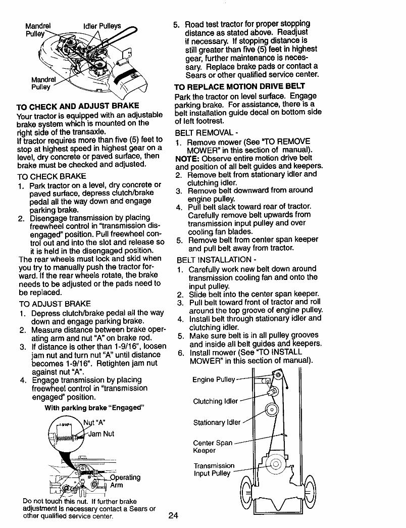
Mandrel Idler PulleysPulle
MandrelPulley
TO CHECK AND ADJUST BRAKE
Your tractor is equipped with an adjustablebrake system which is mounted on theright side of the transaxle.If tractor requires more than five (5) feet tostop at highest speed in highest gear on alevel, dry concrete or paved surface, thenbrake must be checked and adjusted.
TO CHECK BRAKE
1. Park tractor on a level, dry concrete orpaved surface, depress clutch/brakepedal all the way down and engageparking brake.
2. Disengage transmission by placingfreewheel control in "transmission dis-engaged" position. Pull freewheel con-trol out and into the slot and release soit is held in the disengaged position.
The rear wheels must lock and skid whenyou try to manually push the tractor for-ward. If the rear wheels rotate, the brakeneeds to be adjusted or the pads need tobe replaced.
TO ADJUST BRAKE
1. Depress clutch/brake pedal all the waydown and engage parking brake.
2. Measure distance between brake oper-ating arm and nut "A" on brake rod.
3. If distance is other than 1-9/16", loosenjam nut and turn nut "A" until distancebecomes 1-9/16". Retighten jam nutagainst nut "A".
4. Engage transmission by placingfreewheel control in "transmission
engaged" position.
With perking brake "Engaged"
t "A"
erating
m7_
Do not touch this nut. If further brakeadjustment is necessarycontact a Sears orother qualified service center.
o Road test tractor for proper stoppingdistance as stated above. Readjustif necessary. If stoppingdistance isstillgreater than five (5) feet in highestgear, further maintenance is neces-sary. Replace brake pads or contact aSears or other qualifiedservice center.
TO REPLACE MOTION DRIVE BELT
Park the tractor on level surface. Engageparking brake. For assistance, there is abelt installation guide decal on bottom sideof left footrest.
BELT REMOVAL-
1. Remove mower (See "TO REMOVEMOWER" in this section of manual).
NOTE: Observe entire motion drive beltand position of all belt guides and keepers.2. Remove belt from stationary idler and
clutching idler.3. Remove belt downward from around
engine pulley.4. Pull belt slack toward rear of tractor.
Carefully remove belt upwards fromtransmission input pulley and overcooling fan blades.
5. Remove belt from center span keeperand pull belt away from tractor.
BELT INSTALLATION -
1. Carefully work new belt down aroundtransmission cooling fan and onto theinput pulley.
2. Slide belt into the center span keeper.3. Pull belt toward front of tractor and roll
around the top groove of engine pulley.4. Install belt through stationary idler and
clutching idler.5. Make sure belt is in all pulley grooves
and inside all belt guides and keepers.6. Install mower (See "TO INSTALL
MOWER" in this section of manual).
24
Engine Pulley --_-
Clutching Idler "'_ _ I
KT::P:mission
Input Pulley _ \-:;-;J _ A
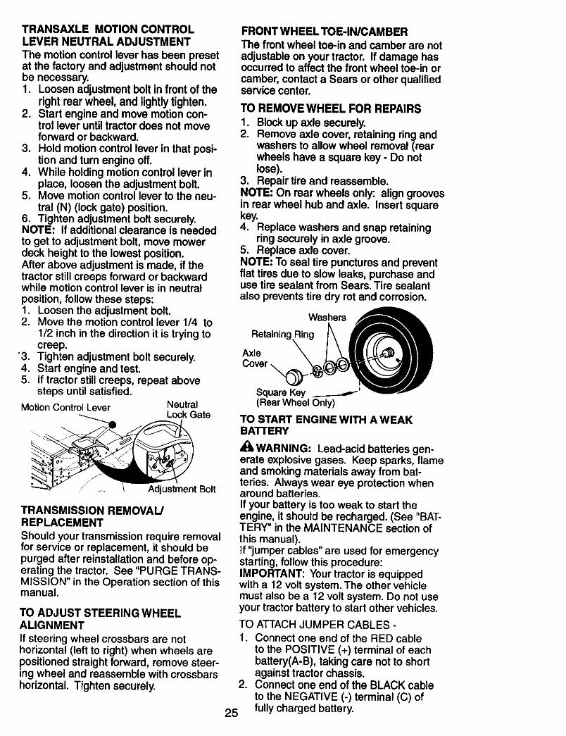
TRANSAXLE MOTION CONTROLLEVER NEUTRAL ADJUSTMENT
The motion control lever has been presetat the factory and adjustment should notbe necessary.1. Loosen adjustment bolt in front of the
rightrearwheel,andlightlytighten.2. Start engine and move motion con-
trol lever until tractor does not moveforward or backward.
3. Hold motion control lever in that posi-tion and turn engine off.
4. While holding motion control lever inplace, loosen the adjustment bolt.
5. Move motion control lever to the neu-tral (N) (lock gate) position.
6. Tighten adjustment bolt securely.NOTE: If additional clearance is neededto get to adjustment bolt, move mowerdeck height to the lowest position.After above adjustment is made, if thetractor still creeps forward or backwardwhile motion control lever is in neutralposition, follow these steps:1. Loosen the adjustment bolt.2. Move the motion control lever 1/4 to
1/2 inch in the direction it is trying tocreep.
'3. Tighten adjustment bolt securely.4. Start engine and test.5. If tractor still creeps, repeat above
steps until satisfied.
MotionControl Lever NeutralLock Gate
....... -... _ Adjustment Bolt
TRANSMISSION REMOVAL/REPLACEMENT
Should your transmission require removalfor service or replacement, it should bepurged after reinstallation and before op-erating the tractor. See "PURGE TRANS-MISSION" in the Operation section of thismanual.
TO ADJUST STEERING WHEELALIGNMENT
If steering wheel crossbars are nothorizontal (left to right) when wheels arepositioned straight forward, remove steer-ing wheel and reassemble with crossbarshorizontal. Tighten securely.
FRONT WHEEL TOE-IN/CAMBERThe front wheel toe-in and camber are notadjustable on yourtractor. If damage hasoccurredto affect the front wheel toe-in orcamber, contact a Sears or other qualifiedservice center.
TO REMOVE WHEEL FOR REPAIRS1. Blockup axle securely.2. Remove axle cover, retaining ringand
washers to allowwheel removal(rearwheels have a square key - Do notlose).
3. Repair tire and reassemble.NOTE: On rear wheels only: aligngroovesin rear wheel hub and axle. Insert squarekey.4. Replace washers and snap retaining
ringsecurely inaxle groove.5. Replace axle cover.NOTE: To seal tire puncturesand preventflat tires due to slow leaks,purchase anduse tire sealant from Sears. Tire sealantalso preventstire dry rotand corrosion.
Washers
Retaining,
Axle
Square Key ._.___--_'(Rear Wheel Only)
TO START ENGINE WITH A WEAKBATTERY
_k WARNING: Lead-acid batteries gen-erate explosive gases. Keep sparks, flameand smoking materials away from bat-teries. Always wear eye protection whenaround batteries.If your battery is too weak to start theengine, it should be recharged. (See "BAT-TERY" in the MAINTENANCE section ofthis manual).If "jumper cables" are used for emergencystarting, follow this procedure:IMPORTANT: Your tractor is equippedwith a 12 volt system. The other vehiclemust also be a 12 volt system. Do not useyour tractor battery to start other vehicles.
.
25
TO ATTACH JUMPER CABLES -1. Connect one end of the RED cable
to the POSITIVE (+) terminal of eachbattery(A-B), taking care not to shortagainst tractor chassis.Connect one end of the BLACK cable
to the NEGATIVE (-) terminal (C) offully charged battery.
3. Connect the other end of the BLACKcable (D) to good chassis ground,away from fuel tank and battery.
TO REMOVE CABLES, REVERSEQRDER -1. BLACK cable first from chassis and
then from the fully charged battery.2. RED cable last from both batteries.
Weak or Dead Fully ChargedBattery Battery
REPLACING BATTERY_I=WARNING: Do not short batteryterminals by allowing a wrench or anyother object to contact both terminals atthe same time. Before connecting battery,remove metal bracelets, wristwatch bands,rings, etc.Positive terminal must be connectedfirst to prevent sparking from accidentalgrounding.1. Lift seat pan to raised position.2. Disconnect BLACK battery cable first
then RED battery cable and carefullyremove battery from tractor.
3. Install new battery with terminals insame position as old battery.
4. First connect RED battery cable topositive (+) terminal with hex bolt andkeps nut as shown. Tighten securely.Slide terminal cover over terminal
5. Connect BLACK grounding cable tonegative (-) terminal with remaininghex bolt and keps nut. Tighten securely.
Seat Pan
TO REPLACE HEADLIGHT BULB1. Raise hood.2. Pull bulb holder out of the hole in the
backside of the grill.3. Replace bulb in holder and push bulb
holder securely back into the hole inthe backside of the gdU.
4. Close hood,INTERLOCKS AND RELAYS
Loose or damaged wiring may causeyour tractor to run poorly, stop running, orprevent it from starting.• Check wiring. See electrical wiring
diagram in the Repair Parts section.TO REPLACE FUSE
Replace with 20 amp automotive-typeplug-in fuse. The fuse holder is locatedbehind the dash.
TO REMOVE HOOD AND GRILL AS-SEMBLY1. Raise hood.2. Unsnap headlight wire connector.3. Stand in front of tractor. Grasp hood at
sides, tilt toward engine and lift off oftractor.
4. When replacing hood, be sure to re-connect the headlight wire connector.
Headlight WireConnector
Terminal
Positiv_(Red)Cable
HexBolt
Negative (Black) Cable
26
ENGINE
Maintenance, repair, or replacement ofthe emission control devices and systems,which are being done at the customers ex-pense, may be performed by any non-roadengine repair establishment or individual.Warranty repairs must be performed by anauthorized engine manufacturer's serviceoutlet.TO ADJUSTTHRO'I'FLE CONTROLCABLE
The throttle control has been preset at thefactory and adjustment should not be nec-essary. Check adjustment as describedbelow before loosening cable. If adjust-ment is necessary, proceed as follows:1. With engine not running, move throttle
control lever from slow to choke posi-tion. Slowly move lever from choke tofast position.
2. Check to see if hole in throttle leverand hole in speed control bracket arealigned.
3. If holes are not aligned, loosen cableclamp screw and align the holes byinserting a pencil or a 1/4" drill bitthrough both holes.
4. Pull throttle cable up to remove slackand tighten cable clamp screw. Re-move alignment pencil or drill bit.
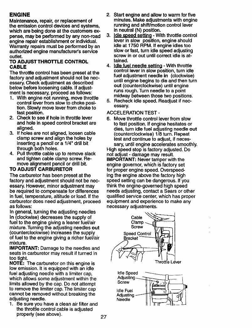
TO ADJUST CARBURETOR
The carburetor has been preset at thefactory and adjustment should not be nec-essary. However, minor adjustment maybe required to compensate for differencesin fuel, temperature, altitude or load. If thecarburetor does need adjustment, proceedas follows:
In general, turning the adjusting needlesin (clockwise) decreases the supply offuel to the engine giving a leaner fuel/airmixture. Turning the adjusting needles out(counterclockwise) increases the supplyof fuel to the engine giving a richer fuel/airmixture.IMPORTANT: Damage to the needles andseats in carburetor may result if turned intoo tight.NOTE: The carburetor on this engine islow emission, it is equipped with an idlefuel adjusting needle with a limiter cap,which allows some adjustment within thelimits allowed by the cap. Do not attemptto remove the limiter cap. The limiter capcannot be removed without breaking theadjusting needle.1. Be sure you have a clean air filter and
the throttle control cable is adjustedproperly (see above).
2. Start engine and allow to warm for fiveminutes. Make adjustments with enginerunning and shift/motion control leverin neutral (N) position.
3. Idle speed settina - With throttle controllever in slow position, engine shouldidle at 1750 RPM. If engine idles tooslow or fast, turn idle speed adjustingscrew in or out until correct idle is at-tained.
4. in - With throttlecontrol lever in slow position, turn idlefuel adjustment needle in (clockwise)until engine begins to die and then turnout (counterclockwise) until engineruns rough.Turn needle to a pointmidway between those two positions.
5. Recheck idle speed. Readjust if nec-essary.
ACCELERATION TEST -6. Move throttle control lever from slow
to fast position. If engine hesitates ordies, turn idle fuel adjusting needle out(counterclockwise) 1/8 turn. Repeattest and continue to adjust, if neces-sary, until engine accelerates smoothly.
High speed stop is factory adjusted. Donot adjust - damage may result.IMPORTANT: Never tamper with theengine governor, which is factory setfor proper engine speed. Overspeed-ing the engine above the factory highspeed setting can be dangerous. If youthink the engine-governed high speedneeds adjusting, contact a Sears or otherqualified service center, which has properequipment and experience to make anynecessary adjustments.
CableClampScrew
Speed ControlBracket
Throttlu L
Idle SpeedAdjusting_T____ |
SorewtlIdle Fuel _ _----_1Adjusting------"_ I_ I cJfn'.I I
.eod,e !!27
Immediatelyprepareyour tractor for stor-age at the end of the season or if the trac-_will not be used for 30 days or more.
WARNING: Never store the tractorwith gasoline in the tank inside a buildingwhere fumes may reach an open flameor spark. Allow the engine to cool beforestoring in any enclosure.
TRACTORRemove mower from tractor for winterstorage. When mower is to be stored for aperiod of time, clean it thoroughly, removeall dirt, grease, leaves, etc. Store in aclean, dry area.1. Clean entire tractor (See "CLEANING"
in the Maintenance section of thismanual).
2. Inspect and replace belts, if necessary(See belt replacement instructions inthe Service and Adjustments section ofthis manual).
3. Lubricate as shown in the Maintenancesection of this manual.
4. Be sure that all nuts, bolts and screwsare securely fastened. Inspect movingparts for damage, breakage and wear.Replace if necessary.
5. Touch up all rusted or chipped paintsurfaces; sand lightly before painting.
BATTERY
• Fully charge the battery for storage.• After a period of time in storage, battery
may require recharging,• To help prevent corrosion and power
leakage during long periods of storage,battery cables should be disconnectedand battery cleaned thoroughly (see "TOCLEAN BATTERY AND TERMINALS" in
the Maintenance section of this manual).• After cleaning, leave cables discon-
nected and place cables where theycannot come in contact with batteryterminals.
• If battery is removed from tractor forstorage, do not store battery directly onconcrete or damp surfaces.
ENGINE
FUEL SYSTEM
IMPORTANT: It is important to preventgum deposits from forming in essentialfuel system parts such as carburetor, fuelhose, or tank during storage.
Also, alcohol blended fuels (called gasoholor using ethanol or methanol) can attractmoisture which leads to separation andformation of acids during storage. Acidicgas can damage the fuel system of anengine while in storage.• Empty the fuel tank by starting the en-
gine and letting it run until the fuel linesand carburetor are empty.
• Never use engine or carburetor cleanerproducts in the fuel tank or permanentdamage may occur.
• Use fresh fuel next season.NOTE: Fuel stabilizer is an acceptablealternative in minimizing the formation offuel gum deposits during storage. Addstabilizer to gasoline in fuel tank or stor-age container. Always follow the mix ratiofound on stabilizer container. Run engineat least 10 minutes after adding stabilizerto allow the stabilizer to reach the car-
buretor. Do not empty the gas tank andcarburetor if using fuel stabilizer.ENGINE OIL
Drain oil (with engine warm) and replacewith clean engine oil. (See "ENGINE" inthe Maintenance section of this manual).CYLINDER(S)1. Remove spark plug(s).2. Pour one ounce of oil through spark
plug hole(s) into cylinder(s).3. Turn ignition key to start position for a
few seconds to distribute oil.4. Replace with new spark plug(s).
OTHER
• Do not store gasoline from one seasonto another.
• Replace your gasoline can if your canstarts to rust. Rust and/or dirt in yourgasoline will cause problems.
• If possible, store your tractor indoorsand cover it to give protection from dustand dirt.
• Cover your tractor with a suitable pro-tective cover that does not retain mois-ture. Do not use plastic. Plastic cannotbreathe which allows condensation toform and will cause your tractor to rust.
IMPORTANT: Never cover tractor whileengine and exhaust areas are still warm.
28
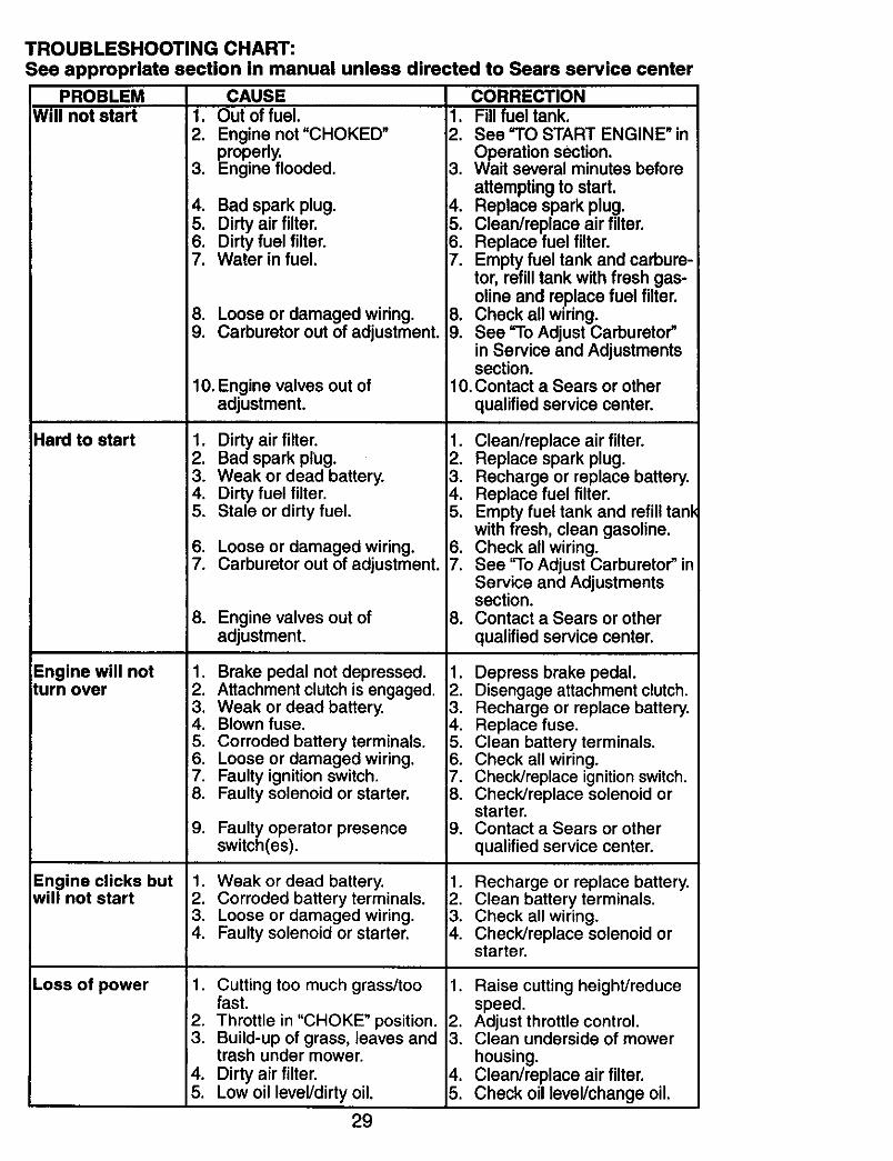
TROUBLESHOOTING CHART:See appropriate section in manual unless directed to Sears service center
PROBLEMWill not start 1.
2.
3.
4.5.6.7.
8.9.
Hard to start
Engine will notturn over
Engine clicks butwill not start
Loss of power
CAUSEOut of fuel.Engine not "CHOKED"properly.Engine flooded.
Bad spark plug.Dirty air filter.Dirty fuel filter.Water in fuel.
Loose or damaged wiring.Carburetor out of adjustment.
10.Engine valves out ofadjustment.
1. Dirty air filter.2. Bad spark plug.3. Weak or dead battery.4. Dirty fuel filter.5. Stale or dirty fuel.
6. Loose or damaged wiring.7. Carburetor out of adjustment.
8. Enginevalves out ofadjustment.
1. Brake pedal not depressed.2. Attachment clutch is engaged.3. Weak or dead battery.4. Blown fuse.5. Corroded battery terminals.6. Loose or damaged wiring.7. Faulty ignition switch.8. Faulty solenoid or starter.
9. Faulty operator presenceswitch(es).
1. Weak or dead battery.2. Corroded battery terminals.3. Loose or damaged wiring.4. Faulty solenoid or starter.
1. Cutting too much grass/toofast.
2. Throttle in "CHOKE" position.3. Build-up of grass, leaves and
trash under mower.4. Dirty air filter.5. Low oil level/dirty oil.
CORRECTION, Fill fuel tank.
2. See "TO START ENGINE" inOperation section.
3. Wait several minutes beforeattempting to start.
4. Replace spark plug.5. Clean/replace air filter.6. Replace fuel filter.7. Empty fuel tank and carbure-
tor, refill tank with fresh gas-oline and replace fuel filter.
B. Check all wiring.9. See "To Adjust Carburetor"
in Service and Adjustmentssection.
10. Contact a Sears or otherqualified service center.
1. Clean/replace air filter.2. Replace spark plug.3. Recharge or replace battery.4. Replace fuel filter.5. Empty fuel tank and refill tanl
with fresh, clean gasoline.6. Check all wiring.7. See "To Adjust Carburetor" in
Service and Adjustmentssection.
8. Contact a Sears or otherqualified service center.
1. Depress brake pedal.2. Disengage attachment clutch.3. Recharge or replace battery.4. Replace fuse.5. Clean battery terminals.6. Check all wiring.7. Check/replace ignition switch.B. Check/replace solenoid or
starter.9. Contact a Sears or other
qualified service center.
1. Recharge or replace battery.2. Clean battery terminals.3. Check all wiring.4. Check/replace solenoid or
starter.
1. Raise cutting height/reducespeed.
2. Adjust throttle control.3. Clean underside of mower
housing.4. Clean/replace air filter.5. Check oil level/change oil.
29
TROUBLESHOOTING CHART:See appropriate ;ection in manual unless directed to Sears service center
PROBLEM CAUSE CORRECTION
Loss of power(continued)
6. Faulty spark plug.
7. Dirty fuel filter.8. Stale or dirty fuel.
9. Water in fuel.
10. Spark plug wire loose.
Excessivevibration
6. Clean and regap or changespark plug.
7. Replace fuel filter.8, Empty fuel tank and refill tank
with fresh, clean gasoline.9, Empty fuel tank and carbure-
tor, refill tank with fresh gas-oline and replace fuel filter.
10. Connect and tighten sparkplug wire.
11. Clean engine air screen/fins.12. Clean/replace muffler.13. Check all wiring.14. See "To Adjust Carburetor"
in Service and Adjustmentssection.
15. Contact a Sears or otherqualified service center.
1. Replace blade. Tighten bladebolt.
i 2. Contact a Sears or otherqualified service center.
3. Tighten loose part(s).Replace damaged parts.
1. Check wiring, switches andconnections, if not correctedcontact a Sears or otherqualified service center.
1. Replace blade. Tighten bladebolt.
2. Level mower deck.3. Clean underside of mower
housing.4. Contact a Sears or other
qualified service center.5. Clean around mandrels to
open vent holes.
1. Remove obstruction.
2. Replace mower drive belt.
3. Replace idler pulley.4. Contact a Sears or other
qualified service center.
1. Place throttle control in"FAST" position.
2. Shift to slower speed.
11. Dirty engine air screen/fins.12. Dirty/cloggedmuffler.13. Loose or damaged wiring.14. Carburetor out of adjustment.
Engine continuesto run whenoperator leavesseat withattachment_-Iutch engaged
Poor cut - uneven
Mower blades willnot rotate
Poor grassdischarge
15. Engine valves out ofadjustment.
1. Worn, bent or loose blade.
2. Bent blade mandrel.
3. Loose/damaged part(s).
1. Faulty operator-safetypresence control system.
.
2.3.
4.
5.
Worn, bent or loose blade.
Mower deck not level.Buildup of grass, leaves, andtrash under mower.Bent blade mandrel.
Clogged mower deck ventfrom build-up of grass, leaves,and trash around mandrels.
1. Obstruction in clutchmechanism.
2. Worn/damaged mower drivebelt.
3. Frozen idler pulley.4. Frozen blade mandrel.
1. Engine speed too slow.
2. Travel speed too fast.
30
TROUBLESHOOTING CHART:See appropriate section in manual unless directed to Sears service center
PROBLEM CAUSE CORRECTION
Poor grassdischarge(continued)
Headlight(s) notworking(if so equipped)
Battery will notcharge
Loss of drive
Engine "backfires"when turningengine "OFF"
3. Wetgmss.
4. Mower deck not level.5. Low/uneven tire air pressure.
6. Worn, bent or loose blade.
7. Buildupof grass, leaves andtrash under mower.
8. Mower drive belt worn.9. Blades improperlyinstalled.
10oImproperblades used.
11, Clogged mower deck ventholes from buildupof grass,leaves, and trash aroundmandrels.
142432 Screw134683 KeeperBeltEngine169183 StrapTorqueLhHydro169182 StrapTorqueRh Hydro137057 Spacer121749X Washer 25/32 x 1-1/4 x 16Ga.STD581075 E-Ring123583X Key,Square121748X Washer 25/32 x 1-5/8 x 16Ga.165596 Shaft AsmCrossTapered165711 SpdngTorsion19171216 Washer 17/32 x 3/4 x 16 Ga.169594 UnkTransaxle188309X428 Console,Shift1702014497H1909121072140608739006001754561913321016600216558918390072140406736804007478041616562317490510165492165580169613169593169612721405087211061414521217000612
ControlBypassHydro20"TiresRetainerSpdng1• Zinc/CadWasher 9/32 x 3/4 x 10 Ga.Bolt RdhdSqneck 3/8-16 x 1.25NutLockFig 3/8-16SpacerRetainerWasher 13/32 x 2 x 10 Ga.Washer Srrted5/16 ID x 1.125BracketShiftMountHub ShiftBoltRdhdSqnk 1/4-20 x 3/4 Gr,5NutCrownlock1/4-20 uncBolt Hex Fin 1/4-20 uncx 1Gr. 5BracketPivotLeverScrew5/16-18 x 5/8Bolt Shoulder5/16-18 x .561Plate FasteningNyliner Snap-In5/8"1DWasher Nyl7/8 ID x .105"HydBolt Shoulder5/16-18 uncBoltRdhdSgnk 5/16-18 uric x 1BoltCarr Sh 3/8-16 x 1-3/4 Gr.5Nut Hex Fig.LockScrew 3/8-16 x .75
NOTE: Allcomponentdimensionsgiven in U.S.inches1 inch= 25.4 mm
39
TRACTOR - - MODEL NUMBER 917.273180STEERING ASSEMBLY
39
I • _ • t
I t
29
steering o1.1t_47
66
48
6 13
87 67
e7
4O
TRACTOR -- MODEL NUMBER 917,273180STEERING ASSEMBLY
184704X428 SteeringWheelAxleAssemblySpindleAssembly,L.H.SplndleAssembly,R.H.Bearing, Race,Thrust,HardenedWasher 25/32 x 1-5/8 x 16 Ga.Ring,KlipDragllnkWasher,LockNutHex JamToplock1/2-20 unfSpacerBrgAxle FrontNut, HexflangeLockShaft Assembly,SteeringBushing,Link,DragWasher 13/32 x 7/8 x 16 Ga.Screw 3/8-16 x 3/4PinRod,TieBushing,SteedngScrew
159946X428 Insert,SteeringWheel19182411 Washer 9/16 x 1-1/2 11 Ga.73540600 NutCrownlock3/8-24159945 Adaptor,SteeringWheel145054x428 Boot,SteeringShaft121749X Washer 25/32 x 1-1/4 x 16 Ga.180640 ExtensionShaft Steering LR.LT184946X505 Cap, Spindle735404007113042016036772110618169827175146169835173966175118175553188967
NutCrownLock1/4-28BoltHex 1/4-28 unfx 1-1/4 Gr,8Spacer Brace AxleBoltRdhdSqnk 3/8-16 x2-1/4Axle, BraceSteeringAsmBracketSuspChassis FrontWasher .781 x 1-1/2 x .14BoltShoulder7/16-20ClipSteeringWasherHardened.793 x 1.637 x ,060
NOTE: All componentdimensionsgiveninU.S. inches1 inch= 25.4 mm
Plug, Drain Oil EasyBushing SnapScrew, Hex Washer Head, Thd.,Roll. 1/4-20 x 3/4Screw Hex Wsh Thdr 3/8-16 x 3/4Washer 9/32 x 7/8 x 16 Ga.Washer 5/16 x 3/4 x 16 Ga.Keps Nut Hex 1/4-20 uncBolt Hex Hd 5/16-18 unc x 1/2Nut Flan-ge M8-1.25Screw 3/8-16 x 1
NOTE: All component dimensions given in U.S. inches1 inch = 25.4 mm
NOTE: All component dimensions given in U.S. inches
1 inch = 25.4 mm
57
SERVICE NOTES
58
SUGGESTED GUIDE FOR SIGHTING SLOPES FOR SAFE OPERATION
ol€O
1. Fold this page along dotted line indicated above.2. Hold page before you so that its left edge is vertically parallel to e tree
trunk or other upright structure.3, Sight across the fold in the direction of hill slope you want to measure.4. Compare the angle of the fold with the slope of the hill.
Your Home
For repair - in your home - of all major brand appliances,lawn and garden equipment, or heating and cooling systems,
no matter who made it, no matter who sold itl
For the replacement parts, accessories andowner's manuals that you need to do-it-yourself.
For Sears professional installationof home appliancesand items like garage door openers and water heaters.
1-800-4-MY-HOME _ Anytime,dayornight(1-800-469-4663) (U.S.A. and Canada)www.sears.com www.sears.ca
Our Home
For repair of carry-in products like vacuums, lawn equipment,and electronics, call or go on-line for the nearest
Sears Parts and Repair Center.
1-800-488-1222 Anytime, day or night (U.S.A. only)
www.sears.com
To purchase a protection agreement (U.S.A.)or maintenance agreement (Canada) on a product serviced by Sears:
1-800-827-6655 (U.S.A) 1-800-361-6665 (Canada)
Para pedirserviciode reparack/_na domicilio,y paraordenarpiezas:
TM SM® Registered Trademark / Trademark / Service Mark of Seam, Roebuck and Co.® Marca Registrada / TMMarca de F_brica / SMMama de Servicio de Sears, Roebuck and Co.
McMarque de commerce/ MOMarque ddpos6ede Sears, Roebuckand Co,