35
www.lg.com OWNER’S MANUAL LCD MONITOR LCD MONITOR MODEL E1910T Please read this manual carefully before operating your set and retain it for future reference. ENGLISH E2210S E2210T E1910S
www.lg.com
OWNER’S MANUAL
LCD MONITOR
LCD MONITOR MODELE1910T
Please read this manual carefully before operating your set and retain it for future reference.
ENG
LISH
E2210S
E2210TE1910S

1
This unit has been engineered and manufactured to ensure your personal safety,however improper use may result in potential electrical shock or fire hazards. Inorder to allow the proper operation of all safeguards incorporated in this display,observe the following basic rules for its installation, use, and servicing.
On Safety
Use only the power cord supplied with the unit. In case you use another powercord, make sure that it is certified by the applicable national standards if not beingprovided by the supplier. If the power cable is faulty in any way, please contact themanufacturer or the nearest authorized repair service provider for a replacement.
The power supply cord is used as the main disconnection device. Ensure that thesocket-outlet is easily accessible after installation.
Operate the display only from a power source indicated in the specifications of thismanual or listed on the display. If you are not sure what type of power supply youhave in your home, consult with your dealer.
Overloaded AC outlets and extension cords are dangerous. So are frayed powercords and broken plugs. They may result in a shock or fire hazard. Call yourservice technician for replacement.
As long as this unit is connected to the AC wall outlet, it is not disconnected fromthe AC power source even if the unit is turned off.
Do not Open the Display:There are no user serviceable components inside. There are Dangerous High Voltages inside, even when the power is OFF. Contact your dealer if the display is not operating properly.
To Avoid Personal Injury :Do not place the display on a sloping shelf unless properly secured.Use only a stand recommended by the manufacturer.Do not drop an object on or apply impact to the product. Do not throw any toysor objects on the product screen. It can cause injury to human, problem to product and damage the display.
To Prevent Fire or Hazards:Always turn the display OFF if you leave the room for more than a short periodof time. Never leave the display ON when leaving the house.Keep children from dropping or pushing objects into the display's cabinetopenings. Some internal parts carry hazardous voltages.Do not add accessories that have not been designed for this display.When the display is to be left unattended for an extended period of time, unplugit from the wall outlet.In the presence of thunder and lightning, never touch the power cord and signalcable because it can be very dangerous. It can cause electric shock.
Important Precautions

2
Important Precautions
On Installation
Do not allow anything to rest upon or roll over the power cord, and do not place thedisplay where the power cord is subject to damage.
Do not use this display near water such as near a bathtub, washbowl, kitchen sink,laundry tub, in a wet basement, or near a swimming pool.
Displays are provided with ventilation openings in the cabinet to allow the releaseof heat generated during operation. If these openings are blocked, built-up heatcan cause failures which may result in a fire hazard. Therefore, NEVER:
Block the bottom ventilation slots by placing the display on a bed, sofa, rug, etc.Place the display in a built-in enclosure unless proper ventilation is provided.Cover the openings with cloth or other material.Place the display near or over a radiator or heat source.
Do not rub or strike the Active Matrix LCD with anything hard as this may scratch,mar, or damage the Active Matrix LCD permanently.
Do not press the LCD screen with your finger for a long time as this may causesome afterimages.
Some dot defects may appear as Red, Green or Blue spots on the screen.However, this will have no impact or effect on the display performance.
If possible, use the recommended resolution to obtain the best image quality foryour LCD display. If used under any mode except the recommended resolution,some scaled or processed images may appear on the screen. However, this ischaracteristic of the fixed-resolution LCD panel.
Leaving a fixed image on the screen for a long time may cause damage to thescreen and cause image burn-in. Make sure to use a screen saver on the product. Burn-in and related problems are not covered by the warranty on this product.
Do not shock or scratch the front and sides of the screen with metallic objects. Otherwise, it may cause damage to the screen.
Make sure the panel faces forward and hold it with both hands to move. If you drop the product, the damaged product can cause electric shock or fire. Contact an authorized the service center for repair.
Avoid high temperatures and humidity.

Important Precautions
3
On Cleaning
Unplug the display before cleaning the face of the display screen.Use a slightly damp (not wet) cloth. Do not use an aerosol directly on the displayscreen because over-spraying may cause electrical shock.When cleaning the product, unplug the power cord and scrub gently with a softcloth to prevent scratching. Do not clean with a wet cloth or spray water or otherliquids directly onto the product. An electric shock may occur. (Do not usechemicals such as benzene, paint thinners or alcohol) Spray water onto a soft cloth 2 to 4 times, and use it to clean the front frame;wipe in one direction only. Too much moisture may cause staining.
On Repacking
Do not throw away the carton and packing materials. They make an idealcontainer in which to transport the unit. When shipping the unit to anotherlocation, repack it in its original material.
On Disposal
The fluorescent lamp used in this product contains a small amount of mercury.Do not dispose of this product with general household waste.Disposal of this product must be carried out in accordance to the regulations ofyour local authority.

4
Accessories
!!! Thank for selecting LGE products !!!
Please make sure the following items are included with yourmonitor. If any items are missing, contact your dealer.
User's Guide/Cards Power Cord
15-pin D-Sub Signal Cable(To set it up, this signal cable may be
attached to this product beforeshipping out.)
DVI-D Signal Cable(This feature is not available in all
countries.)(Only E1910T/E2210T )
NOTEThis accessories may look different from those shown here.User must use shielded signal interface cables (D-sub 15 pin cable, DVI-D cable) with ferritecores to maintain standard compliance for the product.

Connecting the Display
5
Before setting up the monitor, ensure that the power to the monitor, the computersystem, and other attached devices is turned off.
Connecting the stand
1. Place the monitor with its front facing downward on a soft cloth.
2. Assemble the Stand Body into theproduct in the correct direction as shown inthe picture. Make sure you push it until youhear it “click”.
3. Assemble the Stand Base(Front,Rear) into the Stand Body in thecorrect direction.
4. Tie down the base lock to perpendicularity direction.
5. Once assembled take the monitor up carefully and face the front side.
ImportantThis illustration depicts the general model of connection. Your monitor may differ fromthe items shown in the picture.Do not carry the product upside down holding only the stand base. The product mayfall and get damaged or injure your foot.
.
Stand Body
Hinge Body
Stand Body
Stand Base

6
Connecting the Display
..
Disassembling the stand1. Put a cushion or soft cloth on aflat
surface.
3. Change your lock on the product as it follows and turn it in the arrow direction.
2. Place the monitor face Down on thecushion or soft cloth.
If you can't release the stand base even the locking knob is at a releaseposition, Please push the indicated knob down and retry it.

7
Connecting the Display
4. Pull out the Stand to remove.
5. Pushing the PUSH button, Take the stand body from hinge body.
Good Position Bad Position
Warning:You can hurt your finger.

8
Connecting the Display
Before setting up the monitor, ensure that the power to the monitor,the computer system, and other attached devices is turned off.
Positioning your display
-After installation, adjust the angle as shown below.
1. Adjust the position of the panel in various ways for maximum comfort.
Tilt Range : -5˚ to 15˚
ERGONOMICIt is recommended that in order to maintain an ergonomic and comfortable viewing position,the forward tilt angle of the monitor should not exceed 5 degrees.
Do not touch or press the screen whenadjusting the angle of the monitor.
When adjusting the angle of the screen, donot put your finger(s) in between the head ofthe monitor and the stand body. You canhurt your finger(s).

9
Connecting the Display E1910T/E2210T
NOTE‘ Self Image Setting Function’? This function provides the user with optimal displaysettings.When the user connects the monitor for the first time, this function automatically adjuststhe display to optimal settings for individual input signals. ‘AUTO’ Function? When you encounter problems such as blurry screen, blurred letters, screenflicker or tilted screen while using the device or after changing screen resolution, press theAUTO function button to improve resolution.
A
BConnect DVI-D(Digital signal) CableConnect D-sub(Analog signal) Cable
1. Before setting up the monitor, ensure that the power to the monitor, the computersystem, and other attached devices is turned off.
2. Connect signal input cable and power cord in order, then tighten the screwof the signal cable.
Connecting with the PC
1 2
PC
PC
AB
Wall-outlet type
Mac adapter : For Apple Macintosh use, aseparate plug adapter is needed to change the15 pin high density (3 row) D-sub VGAconnector on the supplied cable to a 15 pin 2row connector.
When using a D-Sub signal input cable connectorfor Macintosh
Varies according to model.
DVI-D (This feature is not available in all countries.)
NOTE This is a simplified representation of the rear view.This rear view represents a general model; your display may differ from the view as shown.
3. Press the power button on the front panel to turn the power on. When monitor power isturned on, the 'Self Image Setting Function' is executed automatically.(Only Analog Mode)
Power Button
Connect the signal input cable and tightenit up by turning in the direction of the arrow as shown in the figure.

10
Connecting the Display E1910S/E2210S
NOTE‘ Self Image Setting Function’? This function provides the user with optimal displaysettings.When the user connects the monitor for the first time, this function automatically adjuststhe display to optimal settings for individual input signals. ‘AUTO’ Function? When you encounter problems such as blurry screen, blurred letters, screenflicker or tilted screen while using the device or after changing screen resolution, press theAUTO function button to improve resolution.
A Connect D-sub(Analog signal) Cable
1. Before setting up the monitor, ensure that the power to the monitor, the computersystem, and other attached devices is turned off.
2. Connect signal input cable and power cord in order, then tighten the screwof the signal cable.
Connecting with the PC
1 2
PCA
Wall-outlet type
Mac adapter : For Apple Macintosh use, aseparate plug adapter is needed to change the15 pin high density (3 row) D-sub VGAconnector on the supplied cable to a 15 pin 2row connector.
When using a D-Sub signal input cable connector forMacintosh
Varies according to model.
3. Press the power button on the front panel to turn the power on. When monitor power isturned on, the 'Self Image Setting Function' is executed automatically.
Power Button
NOTE This is a simplified representation of the rear view.This rear view represents a general model; your display may differ from the view as shown.
Connect the signal input cable and tightenit up by turning in the direction of the arrow as shown in the figure.
11
Control Panel Functions
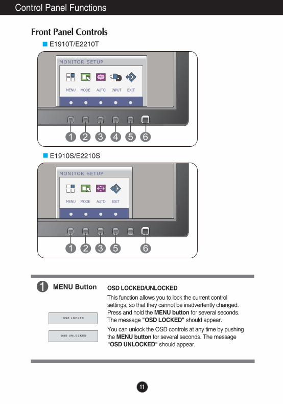
Front Panel Controls
MENU Button OSD LOCKED/UNLOCKED
This function allows you to lock the current controlsettings, so that they cannot be inadvertently changed.Press and hold the MENU button for several seconds.The message "OSD LOCKED" should appear.
You can unlock the OSD controls at any time by pushingthe MENU button for several seconds. The message"OSD UNLOCKED" should appear.
E1910T/E2210T
E1910S/E2210S

12
Control Panel Functions
AUTO Button AUTO IMAGE ADJUSTMENTWhen adjusting your display settings, always press theAUTO button before entering the On ScreenDisplay(OSD). (Only Analog Mode)
This will automatically adjust your display image to theideal settings for the current screen resolution size(display mode).
The best display mode isE1910T/E1910S : 1280 x 1024E2210T/E2210S : 1680 x 1050
INPUT Button
Use this button to turn the display on or off.
The power indicator stays white if the display is runningproperly (On Mode). If the display is in Sleep Mode(Energy Saving), the power indicator is blinking white.
Power Button &Power Indicator
When two input signals are connected, you can select theinput signal (D-SUB/DVI) you want. When only one signalis connected, it is automatically detected. The defaultsetting is D-Sub.
(Only E1910T/E2210T )
(SOURCE Hot key)
Exit the OSD(On Screen Display).EXIT Button
MODE Button Use this button to enter F-ENGINE, ORIGINALRATIO(Only E2210T/E2210S),PHOTO EFFECTmenus.For more information, refer to page 19.

13
On Screen Display (OSD) Control Adjustment
Screen Adjustment
Making adjustments to the image size, position and operatingparameters of the display is quick and easy with the On ScreenDisplay Control system. A short example is given below to familiarize you with the use of thecontrols. The following section is an outline of the availableadjustments and selections you can make using the OSD.
To make adjustments in the On Screen Display, follow these steps:
Press the discretionary Button, then the main menu of the OSD appears.
To access a control, use the corresponding Buttons.
Use the / Buttons to adjust the image to the desired level. Use the Button to select other sub-menu items.
Press the EXIT Button to exit from the OSD.
1
2
3
4

14
On Screen Display(OSD) Selection and Adjustment
The following table indicates all the On Screen Display control, adjustment,and setting menus.
NORMALMOVIEINTERNET
F-ENGINE To select or customize desiredimage settings
: D-SUB(Analog signal) input : DVI-D(Digital signal) input
DSUB
DVI-D
DSUB
DVI-D
LANGUAGEPOWER INDICATOR
WHITE BALANCE
FACTORY RESET
To customize the screen statusfor a user's operatingenvironment
OTHERS
HORIZONTAL
VERTICAL
CLOCK
PHASE
DISPLAY To adjust the position of thescreen
COLOR TEMP (PRESET / USER)
GAMMA
COLOR To customize the color of thescreen
BRIGHTNESS
CONTRAST
SHARPNESS
PICTURE To adjust the brightness, contrastand sharpness of the screen
NOTE The order of icons may differ depending on the model (14~23).
DSUB
DVI-D
DSUB
DVI-D
DSUB
DSUB
DSUB
DVI-D
DSUB
DVI-D
DSUB
WIDEORIGINAL
ORIGINALRATIO(Only E2210T/E2210S)
To adjust the image sizeDSUB
DVI-D
Main menu Sub-menu Supported input Description
To improve the clarity andstability of the screen
NORMALGAUSSIAN BLURSEPIAMONOCHROME
PHOTO EFFECT
To adjust screen color modeDSUB
DVI-D

15
On Screen Display(OSD) Selection and Adjustment
You were introduced to the procedure of selecting and adjusting an itemusing the OSD system. Listed below are the icons, icon names, and icondescriptions of the all items shown on the Menu.
Sub-menus
NOTEOSD (On Screen Display) menu languages on the monitor may differ from the manual.
Menu Name
Icons
ButtonTipExit
Adjust (Decrease/Increase)Select another sub-menuRestart to select sub-menu
Press the MENU Button, then the main menu of the OSD appears.

16
On Screen Display(OSD) Selection and Adjustment
Main menu Sub menu Description
Exit : Exit: Decrease: Increase: Select another sub-menu: Restart to select sub-menu
BRIGHTNESS
CONTRAST
SHARPNESS
To adjust the brightness of the screen.
To adjust the contrast of the screen.
To adjust the clearness of the screen.
PRESET Select the screen color. • sRGB: Set the screen color to fit the
sRGB standard colorspecification.
• WARM: Set the screen to warm color temperature .
• MEDIUM: Set the screen to medium color temperature.
• COOL: Set the screen to cool colortemperature.
REDSet your own red color levels.
GREENSet your own green color levels.
BLUESet your own blue color levels.
GAMMA Set your own gamma value. : 0 / 1 / 2On the monitor, high gamma valuesdisplay whitish images and lowgamma values display blackishimages.
COLOR TEMP
USER
Exit : Exit: Decrease: Increase: Select another sub-menu: Restart to select sub-menu

17
On Screen Display(OSD) Selection and Adjustment
Main menu Sub menu Description
CLOCK
PHASE
To minimize any vertical bars orstripes visible on the screenbackground.The horizontal screen size will alsochange.
To adjust the focus of the display. This item allows you to remove anyhorizontal noise and clear or sharpenthe image of characters.
HORIZONTAL
VERTICAL
To move image left and right.
To move image up and down.
E1910T/E2210T
E1910S/E2210S
Exit : Exit: Decrease: Increase: Select another sub-menu: Restart to select sub-menu

18
On Screen Display(OSD) Selection and Adjustment
Press the , buttons to resetimmediately.
Main menu Sub menu Description
To choose the language in which thecontrol names are displayed.
LANGUAGE
WHITEBALANCE
If the output of the video card isdifferent the required specifications,the color level may deteriorate dueto video signal distortion. Using thisfunction, the signal level is adjustedto fit into the standard output level ofthe video card in order to provide theoptimal image.Activate this function when whiteand black colors are present in thescreen.
Restore all factory default settings except"LANGUAGE."
FACTORYRESET
POWERINDICATOR
Use this function to set the powerindicator on the front side of the monitorto ON or OFF.If you set OFF, it will go off. If you set ON at any time, the powerindicator will automatically be turned on.
NOTE If this does not improve the screen image, restore the factory default settings. If necessary, execute theWHITE BALANCE function again. This function will be enabled only when the input signal is an analogsignal.
Exit : Exit: Decrease: Increase: Select another sub-menu: Restart to select sub-menu

19
On Screen Display(OSD) Selection and Adjustment
You were introduced to the procedure of selecting and adjusting an itemusing the OSD system. Listed below are the icons, icon names, and icondescriptions of the all items shown on the Menu.
Sub-menus
NOTEOSD (On Screen Display) menu languages on the monitor may differ from the manual.
Menu Name
Icons
ButtonTip
Press the MODE Button, then the main menu of the OSD appears.
Sub-menus
ExitAdjust (Decrease/Increase)Restart to select sub-menu
Icons
E1910T/E1910S E2210T/E2210S
20
On Screen Display(OSD) Selection and Adjustment
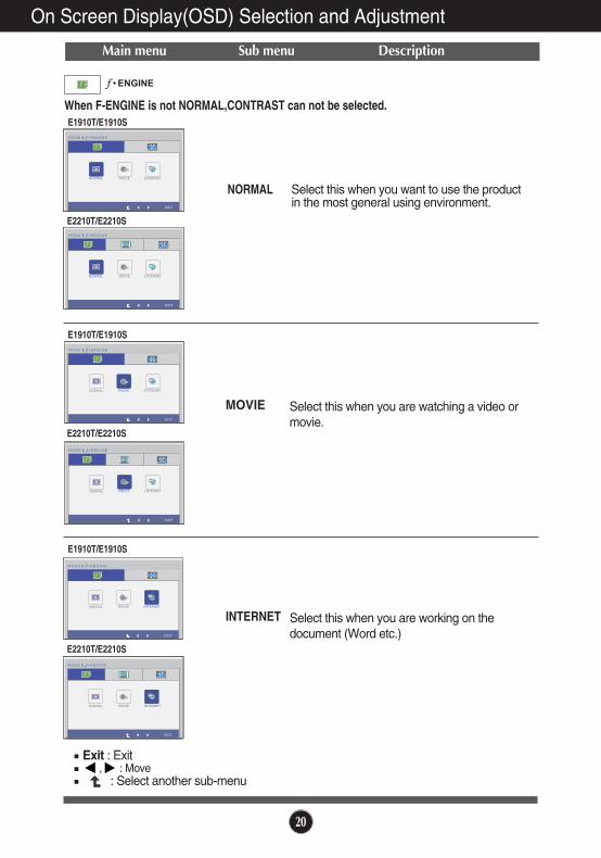
Main menu Sub menu Description
NORMAL Select this when you want to use the productin the most general using environment.
MOVIE Select this when you are watching a video ormovie.
INTERNET Select this when you are working on thedocument (Word etc.)
Exit : Exit, : Move
: Select another sub-menu
When F-ENGINE is not NORMAL,CONTRAST can not be selected.E1910T/E1910S
E2210T/E2210S
E1910T/E1910S
E2210T/E2210S
E1910T/E1910S
E2210T/E2210S

21
On Screen Display(OSD) Selection and Adjustment (Only E2210T/E2210S)
Main menu Sub menu Description
Change the input image signal ratio tooriginal.
WIDE
ORIGINAL
Switch to full screen mode according toinput image signal.
* This function works only if inputresolution is lower than monitor ratio(16:10).
Exit : Exit, : Move
: Select another sub-menu

22
On Screen Display(OSD) Selection and Adjustment
Main menu Sub menu Description
E1910T/E1910S
E2210T/E2210S
E1910T/E1910S
E2210T/E2210S
When PHOTO EFFECT is not NORMAL,CONTRAST can not be selected andCOLOR is grey.When COLOR is selected down, PHOTO EFFECT is back toNORMAL and CONTRAST can be selected now.PHOTO EFFECT and F-ENGINE should not be unnormal at the same time.
NORMAL The Photo Effect function is disabled.
GAUSSIANBLUR
This menu changes the screen to be morecolorful and smoother.

On Screen Display(OSD) Selection and Adjustment
23
Main menu Sub menu Description
Exit : Exit, : Move
: Select another sub-menu
E1910T/E1910S
E2210T/E2210S
E1910T/E1910S
E2210T/E2210S
SEPIA This menu changes the screen to beSepia tone (brown color).
MONOCH-ROME
This menu changed the screen to beGray tone(black-and-white Picture) .

24
Troubleshooting
No image appears
Check the following before calling for service.
No image appears
Do you see a "OSD LOCKED" message on the screen?
� Is the power cord of thedisplay connected?
� Is the power indicatorlight on?
� Is the power indicatorflickering?
� Do you see an "OUT OFRANGE" message onthe screen?
� Do you see a "CHECKSIGNAL CABLE"message on thescreen?
• Check and see if the power cord is connectedproperly to the power outlet.
• Press the Power button.
• If the display is in power saving mode, try movingthe mouse or pressing any key on the keyboard tobring up the screen.
• Try to turn on the PC.
• This message appears when the signal from thePC (video card) is out of horizontal or verticalfrequency range of the display. See the'Specifications' section of this manual andconfigure your display again.
• This message appears when the signal cablebetween your PC and your display is notconnected. Check the signal cable and try again.
• You can secure the current control settings,so that they cannot be inadvertently changed.You can unlock the OSD controls at any timeby pushing the MENU button for severalseconds: the message “OSD UNLOCKED” will appear.
� Do you see “OSDLOCKED” when youpush MENU button?

25
Troubleshooting
Display image is incorrect
� Display Position isincorrect.
� On the screenbackground, verticalbars or stripes arevisible.
� Any horizontal noiseappearing in anyimage or charactersare not clearlyportrayed.
• Press the AUTO button to automatically adjustyour display image to the ideal setting. If the results are unsatisfactory, adjust the imageposition using the H position and V position iconin the on screen display.
• Press the AUTO button to automatically adjustyour display image to the ideal setting.If the results are unsatisfactory, decrease thevertical bars or stripes using the CLOCK icon inthe on screen display.
• Press the AUTO button to automatically adjustyour display image to the ideal setting.If the results are unsatisfactory, decrease the horizontal bars using the PHASE icon in the on screen display.
• Check Control Panel --> Display --> Settingsand adjust the display to the recommendedresolution or adjust the display image to the idealsetting. Set the color setting higher than 24 bits(true color).
IMPORTANTCheck Control Panel --> Display --> Settings and see if the frequency or theresolution were changed. If yes, readjust the video card to the recommendresolution.If the recommended resolution (optimal resolution) is not selected, letters may beblurred and the screen may be dimmed, truncated or biased. Make sure to selectthe recommend resolution. The setting method can differ by computer and O/S (Operation System), and resolution mentioned above may not be supported by the video card performance. In this case, please ask to the computer or the video card manufacturer.

26
Display image is incorrect
Troubleshooting
� The screen color ismono or abnormal.
� The screen blinks.
• Check if the signal cable is properly connectedand use a screwdriver to fasten if necessary.
• Make sure the video card is properly inserted inthe slot.
• Set the color setting higher than 24 bits (true color)at Control Panel - Settings.
• Check if the screen is set to interlace mode and ifyes, change it to the recommend resolution.
Do you see an "Unrecognized monitor, Plug&Play (VESADDC) monitor found" message?
� Have you installed thedisplay driver?
• Be sure to install the display driver from the displaydriver CD (or diskette) that comes with yourdisplay. Or, you can also download the driver fromour web site: http://www.lg.com.
• Make sure to check if the video card supportsPlug&Play function.

27
48.2 cm (19 inch) Flat Panel Active matrix-TFT LCD Anti-Glare coating Visible diagonal size : 48.2 cm0.294 x 0.294 mm (Pixel pitch)
Display
Horizontal Freq. 30 kHz to 83 kHz (Automatic)Vertical Freq. 56 Hz to 75 Hz (Automatic)Input Form Separate Sync.
Digital
Sync Input
Signal Input 15 pin D-Sub ConnectorDVI-D Connector (Digital)
Input Form RGB Analog (0.7 Vp-p/ 75 ohm), Digital
Video Input
Max VESA 1280 x 1024 @75 HzRecommend VESA 1280 x 1024 @60 Hz
Resolution
Plug&Play
On Mode : 25 W(Typ.)Sleep Mode ≤ 0.2 WOff Mode ≤ 0.15 W
PowerConsumption
Operating ConditionsTemperature 10 ˚C to 35 ˚CHumidity 10 % to 80 % non-Condensing
Storage ConditionsTemperature -20 ˚C to 60 ˚CHumidity 5 % to 90 % non-Condensing
Environmental Conditions
With StandWidth 40.89 cm ( 16.10 inch) Height 42.95 cm ( 16.91 inch) Depth 25.00 cm ( 9.84 inch)
Weight(excl. packing) 2.8 kg (6.26 lb)
Dimensions& Weight
Tilt : -5˚ to 15˚Range
AC 100-240 V~ 50 / 60 Hz 0.8 A Power Input
Attached ( ), Detached ( O )Stand Base
Wall-outlet typePower cord
DDC 2B(Digital),DDC2AB(Anlaog)
Without StandWidth 40.89 cm ( 16.10 inch) Height 33.81 cm ( 13.31 inch) Depth 5.82 cm ( 2.29 inch)
NOTEInformation in this document is subject to change without notice.
Specifications E1910T

28
48.2 cm (19 inch) Flat Panel Active matrix-TFT LCD Anti-Glare coating Visible diagonal size : 48.2 cm0.294 x 0.294 mm (Pixel pitch)
Display
Horizontal Freq. 30 kHz to 83 kHz (Automatic)Vertical Freq. 56 Hz to 75 Hz (Automatic)Input Form Separate Sync.
Sync Input
Signal Input 15 pin D-Sub ConnectorInput Form RGB Analog (0.7 Vp-p/ 75 ohm)
Video Input
Max VESA 1280 x 1024 @75 HzRecommend VESA 1280 x 1024 @60 Hz
Resolution
Plug&Play
On Mode : 25 W(Typ.)Sleep Mode ≤ 0.2 WOff Mode ≤ 0.15 W
PowerConsumption
Operating ConditionsTemperature 10 ˚C to 35 ˚CHumidity 10 % to 80 % non-Condensing
Storage ConditionsTemperature -20 ˚C to 60 ˚CHumidity 5 % to 90 % non-Condensing
Environmental Conditions
With StandWidth 40.89 cm (16.10 inch) Height 42.95 cm (16.91 inch) Depth 25.00 cm ( 9.84 inch)
Weight(excl. packing) 2.8 kg (6.26 lb)
Dimensions& Weight
Tilt : -5˚ to 15˚Range
AC 100-240 V~ 50 / 60 Hz 0.8 A Power Input
Attached ( ), Detached ( O )Stand Base
Wall-outlet typePower cord
DDC 2AB
Without StandWidth 40.89 cm (16.10 inch) Height 33.81 cm (13.31 inch) Depth 5.82 cm ( 2.29 inch)
NOTEInformation in this document is subject to change without notice.
Specifications E1910S
29
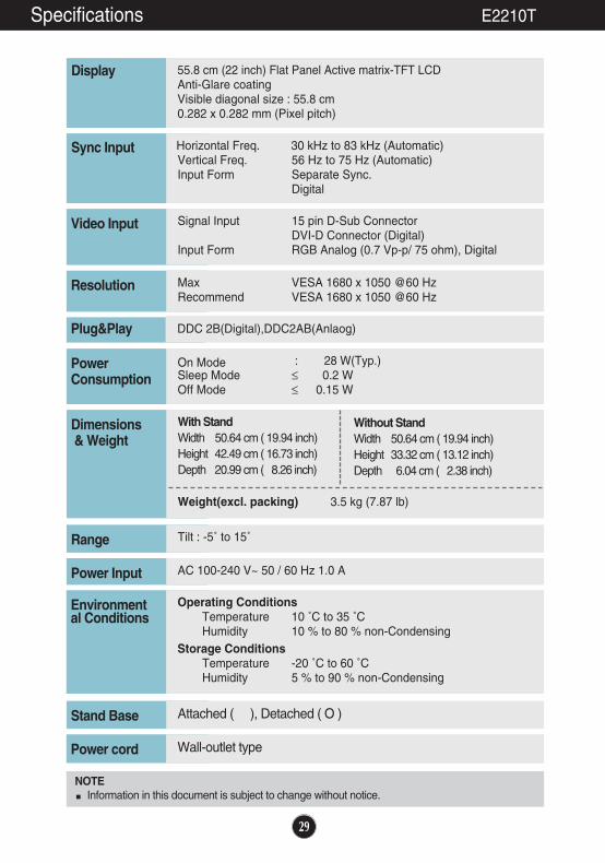
55.8 cm (22 inch) Flat Panel Active matrix-TFT LCD Anti-Glare coating Visible diagonal size : 55.8 cm0.282 x 0.282 mm (Pixel pitch)
Display
Horizontal Freq. 30 kHz to 83 kHz (Automatic)Vertical Freq. 56 Hz to 75 Hz (Automatic)Input Form Separate Sync.
Digital
Sync Input
Signal Input 15 pin D-Sub ConnectorDVI-D Connector (Digital)
Input Form RGB Analog (0.7 Vp-p/ 75 ohm), Digital
Video Input
Max VESA 1680 x 1050 @60 HzRecommend VESA 1680 x 1050 @60 Hz
Resolution
Plug&Play
On Mode : 28 W(Typ.)Sleep Mode ≤ 0.2 WOff Mode ≤ 0.15 W
PowerConsumption
Operating ConditionsTemperature 10 ˚C to 35 ˚CHumidity 10 % to 80 % non-Condensing
Storage ConditionsTemperature -20 ˚C to 60 ˚CHumidity 5 % to 90 % non-Condensing
Environmental Conditions
With StandWidth 50.64 cm ( 19.94 inch) Height 42.49 cm ( 16.73 inch) Depth 20.99 cm ( 8.26 inch)
Weight(excl. packing) 3.5 kg (7.87 lb)
Dimensions& Weight
Tilt : -5˚ to 15˚Range
AC 100-240 V~ 50 / 60 Hz 1.0 A Power Input
Attached ( ), Detached ( O )Stand Base
Wall-outlet typePower cord
DDC 2B(Digital),DDC2AB(Anlaog)
Without StandWidth 50.64 cm ( 19.94 inch) Height 33.32 cm ( 13.12 inch) Depth 6.04 cm ( 2.38 inch)
NOTEInformation in this document is subject to change without notice.
Specifications E2210T

30
55.8 cm (22 inch) Flat Panel Active matrix-TFT LCD Anti-Glare coating Visible diagonal size : 55.8 cm0.282 x 0.282 mm (Pixel pitch)
Display
Horizontal Freq. 30 kHz to 83 kHz (Automatic)Vertical Freq. 56 Hz to 75 Hz (Automatic)Input Form Separate Sync.
Sync Input
Signal Input 15 pin D-Sub ConnectorInput Form RGB Analog (0.7 Vp-p/ 75 ohm)
Video Input
Max VESA 1680 x 1050 @60 HzRecommend VESA 1680 x 1050 @60 Hz
Resolution
Plug&Play
On Mode : 28 W(Typ.)Sleep Mode ≤ 0.2 WOff Mode ≤ 0.15 W
PowerConsumption
Operating ConditionsTemperature 10 ˚C to 35 ˚CHumidity 10 % to 80 % non-Condensing
Storage ConditionsTemperature -20 ˚C to 60 ˚CHumidity 5 % to 90 % non-Condensing
Environmental Conditions
With StandWidth 50.64 cm ( 19.94 inch) Height 42.49 cm ( 16.73 inch) Depth 20.99 cm ( 8.26 inch)
Weight(excl. packing) 3.5 kg (7.87 lb)
Dimensions& Weight
Tilt : -5˚ to 15˚Range
AC 100-240 V~ 50 / 60 Hz 1.0 A Power Input
Attached ( ), Detached ( O )Stand Base
Wall-outlet typePower cord
DDC 2AB
Without StandWidth 50.64 cm ( 19.94 inch) Height 33.32 cm ( 13.12 inch) Depth 6.04 cm ( 2.38 inch)
NOTEInformation in this document is subject to change without notice.
Specifications E2210S

31
Indicator
On ModeSleep ModeOff Mode
WhiteWhite Blinking
Off
LED ColorMODE
Display Modes (Resolution) Horizontal Freq. (kHz) Vertical Freq. (Hz)
*Recommend Mode
E2210T/E2210S
123456789
10*11
720 x 400640 x 480640 x 480800 x 600800 x 6001024 x 7681024 x 7681152 x 8641280 x 10241280 x 10241680 x 1050
31.46831.46937.50037.87946.87548.36360.12367.50063.98179.97665.290
7060756075607575607560
Specifications
Preset Modes (Resolution)
Display Modes (Resolution) Horizontal Freq. (kHz) Vertical Freq. (Hz)
*Recommend Mode
E1910T/E1910S
12345678
*910
720 x 400640 x 480640 x 480800 x 600800 x 6001024 x 7681024 x 7681152 x 8641280 x 10241280 x 1024
31.46831.46937.50037.87946.87548.36360.12367.50063.98179.976
70607560756075756075

32
Installing the Wall mount plate
This monitor satisfies the specifications of the Wall mount plate orthe interchange device.
1. Place the monitor with its front facing downward on a soft cloth.
2. Separate the stand by pushing the PUSH button.
Warning:You can hurt your finger.
Good Position Bad Position

33
Installing the Wall mount plate
Wall mount plate(Separate purchase)This is stand-type or wall mount type and isconnectable with Wall mount plate.Please refer to the installation guide for moredetails, which is provided when Wall mountplate is purchased.
Kensington Security SlotConnected to a locking cable that canbe purchased separately at mostcomputer stores.
<Screw Mounting Interface Dimension>Hole spacing : 75 mm x 75 mm.
3. Install the Wall mount plate.
NOTEVESA compatible only with respect to screw mounting interface dimensions and mounting screw specificationsPlease use VESA standard as below.* 784.8 mm and under (30.9 inch) - Wall Mount Pad Thickness : 2.6 mm- Screw : 4.0 mm x Pitch 0.7 mm x Length 10 mm * 787.4 mm and above (31.0 inch) - Please use VESA standard wall mount pad and screws.

Make sure to read the Safety Precautions before using the product.Keep the OWNER’S MANUAL(CD) in an accessible place for furture reference.The model and serial number of the SET is located on the back or one side of the SET. Record it below should you ever need service.
MODEL
SERIAL
As an ENERGY STAR Partner LGE U. S. A.,Inc. has determined that this product meets the ENERGY STAR guidelines for energy efficiency.
ENERGY STAR is a set of power-saving guidelines issued by the U.S.Environmental Protection Agency(EPA).


