Model No.45-0491
OWNERSMANUAL
PRINTED IN U.S.A. FORM NO. 42432 (08/20/12)
CAUTION:Read Rules for Safe Operation
and Instructions Carefully
• Safety• Assembly• Operation• Maintenance• Parts
50" SNOW THROWER
the fastest way to purchase parts www.speedepart.com
™
2
TABLE OF CONTENTS
SERVICE AND ADJUSTMENTS ...................................20STORAGE .....................................................................21TROUBLESHOOTING ...................................................21REPAIR PARTS ILLUSTRATION ........................22,24,26REPAIR PARTS LIST...........................................23,25,26SLOPE GUIDE ..............................................................27PARTS ORDERING/SERVICE ...................BACK COVER
ACCESSORIES ...............................................................2SAFETY RULES ..............................................................3FULL SIZE HARDWARE CHART .................................4,5CARTON CONTENTS .....................................................6ASSEMBLY ......................................................................7OPERATION ..................................................................18MAINTENANCE ............................................................19
IMPORTANT:Rear wheel weights and tire chains are required to provide extra traction and stabilitywhenusingthissnowthrowerattachment.Theseitemsareavailablewhere you purchased your tractor.
WHEEL WEIGHTS TIRE CHAINS
3
SAFETY
Readandunderstandtheoperatinginstructionsbeforeusing.
Keeptheareaofoperationclearofallpersons,especiallysmallchildrenandpets.Thoroughlyinspecttheareatobeclearedandremovealldoormats,sleds,boards,wiresandotherforeignobjects.Useextremecautionwhenoperatingonorcrossinggravelsurfaces.Neverdirectdischargeatbystandersorallowanyoneinfrontofthesnow thrower.
Do not place hands near rotating parts. Keep clear of the dischargeopeningatalltimes.
Do not place feet near rotating parts.
• Neverallowchildrentooperatetheequipment.• Neverallowadultstooperatetheequipmentwithout
proper instruction.• Disengageallclutchesandshiftintoneutralbefore
starting engine.• Donotoperateequipmentwithoutwearingadequatewinteroutergarments.
• Wearsubstantialfootwearwhichwillprotectfeetandimprovefootingonslipperysurfaces.
• Checkfuelbeforestartingtheengine.Donotremovethefuelcaporfillthefueltankwhiletheengineisrunningorhot.Donotfillthefueltankindoors.Gasolineisanextremelyflammablefuel.
• Makesurethesnowthrowerheightisadjustedtoclearthetypesurfaceitwillbeusedon.
• Donotusethesnowthrowerwithoutwheelweightsattached to the tractor.
• Nevermakeanyadjustmentswhiletheengineisrunning.
• Alwayswearsafetyglassesoreyeshieldduringoperationorwhileperformingadjustmentorrepair.
• Donotplacehandsorfeetnearrotatingparts.Keepclearofthedischargeopeningatalltimes.
• Donotcarrypassengers.• Afterstrikingaforeignobject,stoptheengine,removethewirefromthesparkplugandthenthoroughlyinspectthesnowthrowerfordamage.Repairanydamagebeforerestartingandoperatingthesnowthrower.
• Ifthesnowthrowerstartstovibrateabnormally,stoptheengineimmediatelyandcheckforthecause.Vibrationisgenerallyawarningoftrouble.
• Stoptheenginewheneveryouleavetheoperatingposition,beforeuncloggingthesnowthrowerormakinganyadjustmentsorinspections.
• Takeallpossibleprecautionswhenleavingtheunitunattended.Disengagetheattachmentclutchleverorswitch, lower the snow thrower, shift into neutral, set theparkingbrake,stoptheengineandremovethekey.
• Whencleaning,repairingorinspecting,makecertainallmovingpartshavestopped.Disconnectthesparkplugwireandkeepitawayfromtheplugtopreventaccidental starting.
• Donotrunengineindoorsexceptwhentransportingthesnowthrowerinoroutofthebuilding.Opentheoutsidedoors.Exhaustfumesaredangerous.
• Donotclearsnowacrossthefaceofslopes.Exerciseextremecautionwhenchangingdirectiononslopes.Donotattempttoclearsteepslopes.Refertotheslopeguideonpage35ofthismanual.
• Neveroperatethesnowthrowerwithoutguards,plates or other safety protection devices in place.
• Neveroperatethesnowthrowernearglassenclosures,automobiles,windowwells,dropoffsetc.withoutproperadjustmentofthesnowthrowerdischarge angle.
• Neverrunthesnowthrowerintosnowathighspeeds.• Donotoverloadthesnowthrowercapacitybyattemptingtoclearsnowattoofastarate.
• Neveroperatethesnowthrowerathightransportspeedonslipperysurfaces.Lookbehindandusecarewhenbackingup.
• Watchfortrafficandstayalertwhencrossingoroperating near roadways.
• Disengagepowertothesnowthrowerwhentransporting or when not in use.
• Useonlyattachmentsandaccessoriesapprovedbythemanufacturerofthesnowthrower(suchaswheelweights,counterweights,cabsetc.)
• Neveroperatethesnowthrowerwithoutgoodvisibility.
184045
199683199682
4
HARDWARE PACKAGE CONTENTS
SHOWN ACTUAL SIZE
43063
R19171616
A B C D
I JH LK M
N O
F G
V
P
TU
S
RQ
W
46938
710-0890A
43003
4307043088
43081
47630
4469543082 47810 47572
R19172410
44215
43682
44326
43080
47598
43350
48106
49933
X
43661
E
43182
ATTENTION: Thehardwarebagsmaycontainsomeboltsandnutswhichdonotappearonthispageorthefollowingpage.Thoseboltsandnutswillnotbeneededfortheassemblyofyoursnowthrower.
5
REF. QTY. DESCRIPTIONA 1 Hex Bolt, 3/8" x 3-1/4"B 4 Hex Bolt, 5/16" x 1"C 4 Hex Bolt, 5/16" x 3/4"D 6 Hex Bolt, 1/4" x 1"E 2 HexBolt,5/16"x3/4"(ThreadForming)F 2 Shear Bolt (spare parts)G 2 Shoulder Bolt, Hex HeadH 2 Shoulder Bolt, Round HeadI 6 Carriage Bolt, 3/8" x 1"J 2 Carriage Bolt, 5/16" x 1-3/4"K 2 Carriage Bolt , 5/16" x 1-1/4"L 4 Carriage Bolt, 5/16" x 1"M 1 Carriage Bolt, 5/16" x 3/4"N 1 Washer, 1/2" x 1"O 7 Washer, 1/4"P 19 Washer, 5/16" (Extra washers included)Q 3 Washer, 3/8" StandardR 4 Washer, 1/2" x 1-1/2"S 2 Bowed Washer
REF. QTY. DESCRIPTIONT 1 LockWasher,3/8"U 2 HexLockNut,3/8"V 19 NylockNut,5/16"(2spareparts)W 10 Flanged Nut, 3/8"X 6 Flanged Nut, 1/4"Y 1 SpringZ 3 Chute Keeper
AA 2 Hairpin Cotter, 5/64"BB 1 Hairpin Cotter, 3/32"CC 6 Hairpin CotterDD 2 LockPinEE 2 Clevis Pin, 1/2" x 7/8"FF 1 Plastic CapGG 1 Spacer, 1/4"HH 1 Spacer, 3/8"II 2 Chain, TensioningJJ 2 TailReflectorKK 8 Nylon TieLL 1 CableClip
IMPORTANT: Notallitemssuppliedinthehardwarebagswillbeneededforyourparticulartractor.Unneededitemsmaybediscardedafteryouhavecompletedassemblyandcheckedoperationofunit.DO NOT DISCARD the two spare shearbolts(F)and5/16"nylocknuts(Y).RefertotheServiceandAdjustmentssectiononpage20.
JJ
NOT SHOWN ACTUAL SIZE
II
EE
KK LL
GG
Y Z
46959
AA
731-0851A
BB
47134
DD
43343
CC
43055
43038 1643-60711-0332
46963726-017847788 HA23761
23727
FFHH
25780
6
CARTON CONTENTS
1. HousingAssembly2. ChuteCrankRodAssembly3. SupportTube,CrankRod4. WinchAssembly5. Anti-rotationBracket.6. FrontPulleyFrameBracket(2)7. RearPulleyFrameBracket(2)8. V-Belt, Drive 56" (#48138)9. V-Belt, Drive 55" (#46989)10. V-Belt,Auger(AttachedtoHousingAssembly)
11. ClutchIdlerAssembly12. CableBracket13. L.H.HangerBracket14. R.H.HangerBracket15. Pulley16. ChuteandControlCableAssembly17. Right Hand Side Plate18. Left Hand Side Plate19. SwitchMountingAssembly20. Wire Harness
46989
48138
47846
19
18
5
14
3
12
1316
10
8
1
11
2
17
9
25678 25679
24394
6545065367
25728
24558
76
27016
48883
15
4
67714 42554
20
7
TOOLS REQUIRED FOR ASSEMBLY
(2) 7/16" Wrenches(2) 1/2" Wrenches(2) 9/16" Wrenches(2) 3/4" Wrenches(1) Screw Driver(1) Knife
ASSEMBLY
• Removealllooseparts,partsbagsandhardwarebagsfromthecarton.Layoutandidentifypartsandhardware using the illustrations on pages 4, 5 and 6.
IMPORTANT: Notallitemssuppliedinthehardwarebagwillbeneededforyourparticulartractor.Unneededitemsmaybediscardedafteryouhavecompletedassemblyandcheckedoperationofunit.DO NOT DISCARDthetwospareshearboltsand5/16"nylocknuts.RefertotheServiceandAdjustmentssectiononpage 20.
REMOVAL OF PARTS FROM CARTON
TRACTOR PREPARATION
Beforeperformingtheseinstructions,refertotheServiceandAdjustmentssectionofyourtractorowner'smanualforspecificsafetyinstructions.
• Allowengine,mufflerandexhaustdeflectortocoolbeforebeginning.
• Removeanyfrontorrearattachmentwhichismountedtoyourtractor.
• Removethemowerdeck.Refertoyourtractorowner'smanualforremovalinstructions.Markallloosepartsandsaveforreassembly.
• Removethetractorhood.Refertoyourtractorowner'smanualforremovalinstructions.
IMPORTANT: Right hand (R.H.) and left hand (L.H.) side ofthetractoraredeterminedfromtheoperatorspositionwhile seated on the tractor.
CAUTION: Before starting to assemble thesnowthrower,removethesparkplugwire(s),settheparkingbrakeandremovethekeyfromthe tractor ignition.
STEP 1: (SEE FIGURE 1)• AligntheWinchandBracketAssemblywiththefrontofthetractorframeandinstalltwo3/8"x1"carriageboltsthrougheachsideofthetractorframeandthebracket.Do not install any nuts yet.
FIGURE 1 RIGHT SIDE VIEW
3/8" x 1"CARRIAGE BOLTS (4)
ATTACHING PARTS TO TRACTOR FRAME
FIGURE 2 RIGHT SIDE VIEW
1/2" x 1-1/2"WASHER
3/8" x 1"CARRIAGEBOLT
5/16" x 1"CARRIAGEBOLT
STEP 2: (SEE FIGURE 2)• Oneachsideofthetractorframeinserta3/8"x1"carriageboltanda5/16"x1"carriageboltthroughtheholes shown.
• Installa1/2"x1-1/2"washerontoeachboltunlessthereisanenginemountingplatepresent(depictedwith dotted lines). If there is a plate, do not install a washeronthe3/8"boltinsertedthroughtheplate.
CAUTION: Do notbeginassemblinguntilthetractorengine,mufflerandexhaustdeflectorhavebeenallowedtocooloff.
8
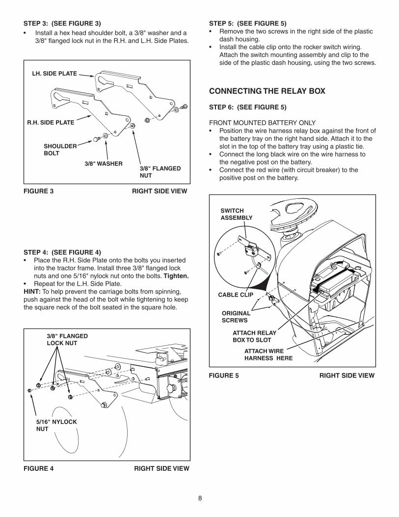
STEP 4: (SEE FIGURE 4)• PlacetheR.H.SidePlateontotheboltsyouinsertedintothetractorframe.Installthree3/8"flangedlocknutsandone5/16"nylocknutontothebolts.Tighten.
• Repeat for the L.H. Side Plate.HINT:Tohelppreventthecarriageboltsfromspinning,pushagainsttheheadoftheboltwhiletighteningtokeepthesquareneckoftheboltseatedinthesquarehole.
3/8" FLANGEDLOCK NUT
5/16" NYLOCKNUT
FIGURE 4 RIGHT SIDE VIEW
STEP 3: (SEE FIGURE 3)• Installahexheadshoulderbolt,a3/8"washeranda3/8"flangedlocknutintheR.H.andL.H.SidePlates.
FIGURE 3 RIGHT SIDE VIEW
3/8" WASHER
SHOULDER BOLT
3/8" FLANGEDNUT
R.H. SIDE PLATE
LH. SIDE PLATE
STEP 6: (SEE FIGURE 6)
HINT:Donotcompletelytightentheplastictiesuntilsoinstructed in step 7.
• Positionthewireharness'blackrelayboxagainstthefrontofthebatterytrayontherighthandside.Attachittotheslotinthetopofthebatterytrayusingaplastic tie.
• Routetheendofthewireharnesswiththegreenandblackwiresaroundbehindthetractor'swiringandthen forward along the right side of the tractor.
• Looselyattachthewireharnesstorearoftherighthand side plate installed in step 4, and to the right frontcornerofthetractorframeusingtwoplasticties.
• Routetheotherendofthewireharnesswiththebrownandblackwiresaroundbehindthebatterycableontheleftsideofthebatteryandthenalongtheleft side of the tractor.
• Looselyattachthewireharnesstotheholeatthebottomleftcornerofthelowerdashusingaplastictie.
• Looselyattachthewireharnesstotherearofthelefthand side plate installed in step 4, and to the left front cornerofthetractorframe,usingtwoplasticties.
STEP 5: (SEE FIGURE 5)• Removethetwoscrewsintherightsideoftheplastic
dash housing. • Installthecableclipontotherockerswitchwiring.Attachtheswitchmountingassemblyandcliptotheside of the plastic dash housing, using the two screws.
FIGURE 5 RIGHT SIDE VIEW
SWITCHASSEMBLY
ATTACH RELAYBOX TO SLOT
ATTACH WIRE HARNESS HERE
CABLE CLIP
ORIGINALSCREWS
CONNECTING THE RELAY BOX
STEP 6: (SEE FIGURE 5)
FRONT MOUNTED BATTERY ONLY• Positionthewireharnessrelayboxagainstthefrontofthebatterytrayontherighthandside.Attachittotheslotinthetopofthebatterytrayusingaplastictie.
• Connectthelongblackwireonthewireharnesstothenegativepostonthebattery.
• Connecttheredwire(withcircuitbreaker)tothepositivepostonthebattery.
9
INSTALL HANGER BRACKETS AND SHOULDER BOLTS TO OUTSIDE OF FRAME
STEP 9: (SEE FIGURE 7)• Removethebolt,ifpresent,intheholedirectlybehindthebrakerodontheleftsideofthetractorframe.
• AttachtheL.H.HangerBracket(tubefacingout)totheholeusinga5/16"x3/4"selfthreadingbolt.
• Installaroundheadshoulderboltintotheholethatis9-1/2"totherearoftheboltyoujustinstalled.Secureitwitha3/8"flangenutontheinsideoftheframe.
FIGURE 7 LEFT SIDE VIEW
5/16" x 3/4" SELFTHREADING BOLT
L.H. HANGER BRACKET
BRAKE ROD
3/8" FLANGEDNUT
SHOULDERBOLT
5/16" x 3/4" SELFTHREADING BOLT
R.H. HANGER BRACKET
RIGHT END OF BRAKE ROD
3/8" FLANGEDNUT
SHOULDERBOLT
STEP 10: (SEE FIGURE 8)• Removethebracket,ifpresent,fromtheholedirectlybehindtheendofthebrakerodontherightsideofthetractorframe.Storethebracketandbolt.
• AttachtheR.H.HangerBrackettotheholeusinga5/16"x3/4"selfthreadingbolt.
• Installaroundheadshoulderboltintotheholethatis9-1/2"totherearoftheboltyoujustinstalled.Secureitwitha3/8"flangenutontheinsideoftheframe.
FIGURE 8 RIGHT SIDE VIEW
BLACK WIRE
BROWN WIRE
NUT
NUT
WASHERWASHER
WASHERWASHER
FIGURE 6 RIGHT SIDE VIEW
INSTALLING THE WIRE HARNESS
STEP 8:• Connectthethreewiresoftheswitchmountingassemblytothewireswithmatingconnectorsfromthewireharness,joiningtogetherlikecoloredwires.
• Routetheendofthewireharnesswiththegreenandblackwiresaroundbehindthetractor'swiringandthen forward along the right side of the tractor.
• Routetheotherendofthewireharnessaroundtotheleft side of the tractor.
• Looselyattachthewireharnesstorearofeachsideplate installed in step 4, and to the front corners of the tractorframeusingtwoplastictiesperside.
• Connectthewireharnesstothewinchmotorusingthepre-assemblednutandwashers.Placethebrownwireonthetopterminalandtheblackwireonthebottomterminal.Seefigure6.
• Tightentheplasticties.
STEP 7:
REAR MOUNTED BATTERY ONLY• Mountthewireharnessrelayboxinfrontofthesolenoidontherighthandsideofthegastank,attaching it with a plastic tie.
• Attachthelongblackwireofthewireharnessunderthe head of the screw that fastens down the right handsideofthegastank.
• Attachtheredwire(withcircuitbreaker)totherearsolenoidterminalwherethebatterycableisattached.
• Connecttheshortred,blackandgreenwirestothethreewiresoftheswitchmountingassembly,joiningtogetherlikecoloredwires.
10
STEP 12: (SEE FIGURE 10)• Attachthepulley(longendofhubfacingdown)andthe3/8"spacertotheclutch/idlerassembly.Usea3/8"x3-1/4"hexbolt,a3/8"washer,a3/8"lockwasheranda3/8"hexlocknut.
• Insertatensioningchainthroughtheholeshownandattachtheendlinktothespringontheloweridlerarm.
FIGURE 10
FIGURE 9
STEP 11: (SEE FIGURE 9)• Attachthecablebrackettothedoubleholeintheclutch/idlerassemblyasshown,usinga5/16"x3/4"carriageboltanda5/16"nylocknut.Placetheboltinthefrontholeofthebracketandintheendoftheholeclosest to the pulley. Do not tighten yet.
THIS SECTION IS FOR TRACTORS WITH A MANUAL ATTACHMENT CLUTCH If your tractor has an electric attachment clutch go to step 18 on page 12.
FIGURE 12
HEX BOLTS
(#48138) DRIVE BELT
FLAT IDLER PULLEYS
STOPDidyouselectthecorrectdrivebeltforyourtractor?Usingthewronglengthbeltmaycauseprematurebearingorbeltfailure.
STEP 14: (SEE FIGURE 12)• Twodifferentlengthdrivebeltsareincludedwithyoursnowthrower.Usethelonger,56"drivebelt(#48138) ontractorswithmanualattachmentclutches.
• Slightlyloosenthehexboltnexttotheflatidlerpulley.Installthedrivebeltdownbetweenthehexboltandtheflatidlerpulleywiththeflatsideofthebeltagainstthepulley.Retightenthehexbolt.
• LoopthebeltaroundthelargeV-pulley,placingitbetweentheV-pulleyandthehexboltnexttothepulley.Placethebelttotheinsideoftheotherflatidlerpulley.
5/16" x 1"HEX BOLT
5/16" x 3/4"HEX BOLT
5/16"NYLOCKNUT5/16" WASHER
(2) 5/16"WASHERS
FIGURE 11
STEP 13: (SEE FIGURE 11)• Attacheachrearpulleyframebrackettotheinsideoftheclutch/idlerassemblyusingtwo5/16"x3/4"hexbolts,5/16"washersand5/16"nylocknuts.
• Attacheachfrontpulleyframebrackettotheinsideoftheclutch/idlerassemblyusingtwo5/16"x1"hexbolts,four5/16"washersandtwo5/16"nylocknuts.
3/8" SPACER
PULLEY
3/8" LOCKWASHER
3/8" HEX LOCK NUT 3/8"WASHER
LONG ENDOF HUB
3/8" x 3-1/4"HEX BOLT
TENSIONING CHAIN
CABLEBRACKET
5/16" x 3/4"CARRIAGE BOLT
5/16" NYLOCK NUT
11
ATTACH CLUTCH IDLER ASSEMBLY TO TRACTOR
STEP 16: (SEE FIGURE 14)• Attachtheclutch/idlerassemblytothetractorframe.Hookthenotchedrearpulleyframebracketsontothetwoshoulderboltsassembledtotheoutsideofthetractorframe.LiftthefrontoftheassemblyandattachittotheR.H.andL.H.hangerbracketsusingtwopivotlockpinsand1/8"hairpincotters.
• Looselyattachthemowerclutchcabletotheleftsideofthetractorframewithanylontie.Do not pull the nylontiecompletelytight.Thecablemayneedtoberemovedfromthenylontiewhenusingthemowerdeck.
PIVOT LOCK PIN(use this hole)
SHOULDERBOLT
L.H. HANGERBRACKET
1/8" HAIRPINCOTTER
NYLON TIE
MOWERCLUTCHCABLE
FIGURE 14 VIEWED FROM LEFT SIDE
FIGURE 15 VIEWED FROM UNDERNEATH
FIGURE 13
STEP 15: (SEE FIGURE 13)• Findthecableclipthatisattachedtotheleftsideofthetractorframeunderneaththefootrest.Opentheclipandremovethemowerclutchcable.Do not removetheclipfromthetractorframe.Thecablereattachestotheclipwhenusingthemowerdeck.
• Movetheattachmentclutchleveronthedashpaneltothe disengaged position.
• Placetheclutch/idlerassemblyonthefloorontheleftside of the tractor.
• Attachthetractor'smowerclutchcabletothecablebracketontheclutch/idlerassembly.Securethecablehousingguide(groovedown)tothecablebracketusing the original collar and retainer spring.
• Placea1/4"spacerontheweldedpinontheidlerarm.Hooktheendoftheclutchcablespringoverthepin and secure it with a 1/4" washer and a 5/64" hair cotter pin.
• Aligncablebracketwithweldedpinandtightenthenutassembledinstep11.
5/64" HAIRCOTTER PIN
1/4" WASHER
1/4" SPACER
TRACTOR'SCLUTCH CABLE
CABLEBRACKET
ENGINEPULLEY
HEX BOLT
FLAT IDLERPULLEY
ENGINEPULLEYBELT KEEPERS
STEP 17: (SEE FIGURE 15)• Assemblethedrivebeltontotheenginepulley,routingitthroughtheenginepulleybeltkeepers.
HINT: Youmayneedtoremovethebeltfromthelargepulleyontheclutch/idlerassemblyinordertoassembleitontotheenginepulley.Whenre-assemblingthebeltontothelargepulley,besurethebeltisbetweenthelargepulleyandthehexboltnexttoit.
• Go to step 24 on page 14.
LEFT SIDEOF TRACTOR
12
FIGURE 18
TABLE 1
5/16" x 1" HEX BOLT
5/16" x 3/4"HEX BOLT
5/16" NYLOCK NUT
5/16" WASHER
5/16"NYLOCK NUT
(2) 5/16" WASHERS
STEP 20: (SEE FIGURE 18)• Attacheachrearpulleyframebrackettotheinsideoftheclutch/idlerassemblyusingtwo5/16"x3/4"hexbolts,5/16"washersand5/16"nylocknuts.
• Attacheachfrontpulleyframebrackettotheinsideoftheclutch/idlerassemblyusingtwo5/16"x1"hexbolts,four5/16"washersandtwo5/16"nylocknuts.
THIS SECTION IS FOR TRACTORS WITH AN ELECTRIC ATTACHMENT CLUTCH
3/8" HEXLOCK NUT
SPRING
ATTACHSPRINGHERE
STEP 18: (SEE FIGURE 16)• Turntheclutchidlerassemblyupsidedown.• Hookthespringontotheendoftheboltthatextendsthroughthenutonthebottomoftheupperidlerarm.Installa3/8"hexlocknutontothebolt,leavingenough space for the spring to pivot.
FIGURE 16 BOTTOM VIEW
FIGURE 17
STEP 19: (SEE FIGURE 17)• Inserttensioningchainsthroughtheholesshownandattachtothespringsontheupperandloweridlerarms.
• Installa3/32"hairpincotterinthechainattachedtotheupperidlerarm,placingitinthefifthlinkfromthespring.
TENSIONING CHAIN (lower idler arm)
TENSIONING CHAIN (upper idler arm)
3/32" HAIRPINCOTTER IN5th LINK
STEP 21: (SEE FIGURE 19• Twodifferentlengthdrivebeltsareincludedwithyoursnowthrower.Usetheshorter,55"drivebelt(#46989) on tractors with electric clutches.
• Turntheclutch/idlerassemblyrightsideup.• Slightlyloosenthehexboltnexttotheflatidlerpulley.Installthedrivebeltbetweenthehexboltandtheflatidlerpulley.Retightenthehexbolt.
• LoopthebeltaroundthelargeV-pulley,placingitbetweentheV-pulleyandthehexboltnexttothepulley.
FIGURE 19
STOPDidyouchoosethecorrectdrivebeltforyourtractor?Usingthewronglengthbeltmaycauseprematurebearingorbeltfailure.
(#46989)DRIVE BELT
FLAT IDLERPULLEY
HEX BOLTS
13
STEP 22: (SEE FIGURE 20)• Attachtheclutch/idlerassemblytothetractorframe.Hookthenotchedrearpulleyframebracketsontothetwoshoulderboltsassembledtotheoutsideofthetractorframe.LiftthefrontoftheassemblyandattachittotheR.H.andL.H.hangerbracketsusingtwopivotlockpinsand1/8"hairpincotters.
PIVOT LOCK PIN(use second hole) SHOULDER
BOLT
1/8" HAIRPINCOTTER
L.H. HANGER BRACKET
FIGURE 20 VIEWED FROM LEFT SIDE
STEP 23: (SEE FIGURE 21)• Assemblethedrivebeltontotheenginepulley.Youmayneedtoremovethebeltfromthelargepulleyontheclutch/idlerassemblyinordertoassembleitontotheenginepulley.Whenre-assemblingthebeltontothelargepulley,besurethebeltisbetweenthelargepulleyandthehexboltnexttoit.
• Placetensiononthebeltbypullingtheleftsidetensioning chain out as far as the 3/32" hairpin cotter that was installed in the chain in step 17 will allow. Securethechaininthispositionbyinsertinga1/8"hairpin cotter through the chain.
NOTE;Topreventthechainfromdraggingontheground,looptheendofthechainthoughthepivotlockpin.Refertofigure31onpage16.
• Go to step 24 on page 14.
FIGURE 21 VIEWED FROM UNDERNEATH
1/8"HAIRPINCOTTER
ENGINEPULLEY
HEX BOLTS
FLAT IDLERPULLEY
TENSIONINGCHAIN
LEFT SIDEOF TRACTOR
14
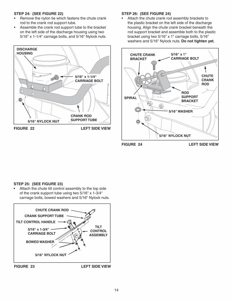
STEP 24: (SEE FIGURE 22)• Removethenylontiewhichfastensthechutecrankrodtothecrankrodsupporttube.
• Assemblethecrankrodsupporttubetothebracketon the left side of the discharge housing using two 5/16"x1-1/4"carriagebolts,and5/16"Nylocknuts.
FIGURE 23 LEFT SIDE VIEW
CHUTE CRANK ROD
CRANK SUPPORT TUBE
TILT CONTROL HANDLE
5/16" x 1-3/4"CARRIAGE BOLT
BOWED WASHER
5/16" NYLOCK NUT
TILT CONTROL
ASSEMBLY
STEP 25: (SEE FIGURE 23)• Attachthechutetiltcontrolassemblytothetopsideofthecranksupporttubeusingtwo5/16"x1-3/4"carriagebolts,bowedwashersand5/16"Nylocknuts.
5/16" NYLOCK NUT
5/16" x 1-1/4"CARRIAGE BOLT
CRANK ROD SUPPORT TUBE
DISCHARGE HOUSING
FIGURE 22 LEFT SIDE VIEW
5/16" NYLOCK NUT
CHUTE CRANK BRACKET
5/16" WASHER
CHUTE CRANK ROD
ROD SUPPORT BRACKET
5/16" x 1"CARRIAGE BOLT
SPIRAL
FIGURE 24 LEFT SIDE VIEW
STEP 26: (SEE FIGURE 24)• Attachthechutecrankrodassemblybracketstotheplasticbracketontheleftsideofthedischargehousing.Alignthechutecrankbracketbeneaththerodsupportbracketandassemblebothtotheplasticbracketusingtwo5/16"x1"carriagebolts,5/16"washersand5/16"Nylocknuts.Do not tighten yet.
15
FIGURE 25 RIGHT SIDE VIEW
CHUTE KEEPER
ANTI-ROTATION BRACKET
1/4" FLANGEDLOCK NUT
1/4" FLATWASHER
1/4" x 1" HEX BOLT
PLASTIC CAP
GREASED SURFACE
FLANGE
STEP 27: (SEE FIGURE 25)• Coatthetopoftheringaroundthedischargeopening
with general purpose grease.• Placethedischargechute(facingforward)ontothering.Placetheanti-rotationbracketontopofthechuteflange,aligningitwiththeholesontherighthandsideoftheflange.Attachthethreechutekeepers(rightsideupasshown)tothebottomoftheflangeusingsix1/4"x1"hexbolts,1/4"flatwashersand1/4"flangedlocknuts.Tighten carefully so that the nuts aresnugbutdonotdigintotheplasticchutekeepers.
• Placetheplasticcapontotheshortendoftheanti-rotationbracket.
• Positionthecrankrodspiral(seefigure24onpage14)sothatitdoesnotrubagainstthebottomsofthenotchesinthechuteflange.Tighten the nuts.
• Checkifthecrankrodrotatesthechutefreely.Ifnot,loosenby1/4turneachofthesixhexboltsholdingthechutekeeperstothechuteflange.
• Securethecontrolcablestothecrankrodsupporttubeusingtwonylonties.
ATTACHING SNOW THROWER TO TRACTOR
FIGURE 26 RIGHT SIDE VIEW
STEP 28: (SEE FIGURE 26)• Placethesnowthroweronaflat,levelsurface.• Extendtheaugerbeltoutbehindthesnowthrower,leavingthebeltassembledtothesnowthrowerpulleys.
• Rollthetractorupbehindthesnowthrower,centeringitbetweenthesnowthrower'smountingplates.
• Liftuponthecrankrodsupporttubetoraisetherear of the snow thrower and align the notches in the mountingplatesalignwiththeshoulderboltsinthetractor'ssideplates.Rollthetractorforward,guidingtheshoulderboltsintothenotches.
• Installthetwo1/2"x7/8"clevispinsand1/8"hairpincotters to secure the snow thrower to the tractor.
1/8" HAIRPINCOTTER
1/2" x 7/8"CLEVIS PIN
TERMINALS
FIGURE 27 RIGHT SIDE VIEW
STEP 29: (SEE FIGURE 27)• Connecttheterminalsofthewireharnessattachedtothetractorwiththewireterminalsofthelimitswitcheson the snow thrower.
16
FIGURE 30 VIEWED FROM UNDERNEATH
INSTALLING THE AUGER BELT
STEP 32: (SEE FIGURE 30)• Startwiththesnowthrowerloweredtotheground.• SwingtheidlerarmovertotheL.H.sideofthetractor.• PlacetheaugerbeltaroundtherearV-pulleyandbetweenthetwoidlerarmpulleys.The"V"sideofthebeltmustbeseatedinthegroovesoftheV-pulleys.
HINT:Ifthebeltistootighttoassemble,trytemporarilyreleasingthespringtensionontheupperdrivebeltandthenturningtherearpulleywhilerollingtheaugerbeltontoit.Ifthebeltisstilltootighttoassemble,tryraisingthesnowthrowertoseeifthebeltislooserinthatposition.
BELT ROUTING DIAGRAM
ENGINE PULLEY
STEP 31: (SEE FIGURE 29)• Checktomakesuretheaugerbeltisstillproperlyseatedaroundthesnowthrower'saugerpulleyandidler pulleys.
IDLER PULLEY
AUGER PULLEYTWIST 1/4 TURN
TWIST 1/4 TURN
IDLER PULLEY
FIGURE 29
FIGURE 28 VIEWED FROM UNDERNEATH
PUSH HERE
1/2" WASHER
5/64" HAIRPINCOTTERWINCH CABLE
LIFT STOPPLATE
LIFT LINK
STEP 30: (SEE FIGURE 28)• Placetheendofthewinchcableontotheliftlink.Placea1/2"washerontothelinkandinstalla5/64"hairpin cotter.
HINT:Pushontheliftstopplatetorotatetheliftlinkintobetterpositiontoinstallthewinchcable.
REARPULLEY
AUGERBELT
IDLER ARM V-PULLEY
IDLER ARMFLAT PULLEY
LEFT SIDEOF TRACTOR
17
INSTALLING THE ATTACHMENT PIN
STEP 58: (REFER BACK TO FIGURE 54 ON PAGE 24)• Liftthefrontofthesnowblowertoaligntheholesinthemountingplatesandthesideplates.Fromtheleftsideofthetractorinserttheattachmentpinthroughtheholes.Secureitwithbyreinstallingthe1/8"hairpincotter.
SETTING THE AUGER BELT TENSION
STEP 33: (SEE FIGURE 31)• Pulltherightsidetensioningchainuntiltheendofthe
spring is pulled into the hole in the side of the Clutch/Idlerassembly.Installa1/8"hairpincotterthroughthe end of the spring, securing it on the outside of the Clutch/Idlerassembly.
IMPORTANT:Forcorrectbelttension,the 1/8" hairpincotter must attach to the end of the spring, not to thechain.
NOTE;Topreventthechainfromdraggingontheground,looptheendofthechainthoughthepivotlockpin.Refertofigure30onpage16.
FIGURE 31 VIEWED FROM UNDERNEATH
CHECKLIST
Before you operate your snow thrower, please review the following checklist to help ensure that you will obtain the best performance from your snow thrower.• Makesureallassemblyinstructionshavebeencompletedwithallboltsandnutsproperlytightened.
• Makesurethecorrectdrivebeltwasinstalled.• Makesurethedrivebeltandaugerbeltareroutedproperlyaroundpulleysandinsideallbeltkeepers.
• Checkdischargechuteforproperrotation.• Checkoperationoftiltcontrolforupperchute.• Verifythatthesnowthrowerraisesandlowers
properly.• Checkskidshoeadjustment.(RefertotheServiceandAdjustmentssection.)
REAR REFLECTORS
ATTACH REFLECTORS TO REAR FENDER
STEP 34: (SEE FIGURE 32)• Ifyourtractorisnotequippedwithrearreflectors,assemblethesuppliedrearreflectorstotherearfender.Placethereflectorsasclosetothebottomofthe fender and as far apart as the shape of the fender will allow.
FIGURE 32
RIGHT SIDE OF TRACTOR
1/8" HAIRPIN COTTER
IDLER FLAT PULLER
AUGER BELT
18
OPERATION
KNOW YOUR SNOW THROWERRead this owner's manual and safety rules before operating your snow thrower.Comparetheillustrationbelowwithyoursnowthrowertofamiliarizeyourselfwiththevariouscontrolsandtheirlocations.
CHUTE TILT HANDLE Pivots the Upper Chute up or down to control the angle and distance of discharge.CRANK ROD Rotates the Lower and Upper Chutes to control the direction of discharge.TOGGLE SWITCH Used to raise or lower the snow thrower to transport or operating position.UPPER AND LOWER DISCHARGE CHUTE Controls direction and height of snow discharge.
SCRAPER PLATEReplaceableplatethatabsorbswearandimpactfromcontactwithground.SKID SHOEControlsamountofclearancebetween the scraper plate and the ground.SPIRAL AUGER, R.H. & L.H. Feed snow to theimpellerfanatthecenterofthehousing.
BEFORE STARTING• Usetheendofassemblychecklisttoverifythatallinstructionshavebeenproperlycompleted.
• Makesuretheskidshoesareadjustedtomaintainadequategroundclearancebetweenthesnowthrowerandthetypeofsurfacetobecleared.(RefertotheServiceandAdjustmentssection.)
• Makesurethetractorenginehasthecorrectoilfor winter operation (SAE 5W-30). Refer to tractor owner'smanual.
HOW TO START YOUR SNOW THROWER• Thetractorshouldbesittingwiththeenginerunningatfullthrottle.Movetheattachmentclutchtotheengagedposition,startingthesnowthrowerbeforethe tractor clutch is engaged.
HOW TO STOP YOUR SNOW THROWER• Tostopthesnowthrower,disengagethetractor'sattachmentclutchleverformanualclutchesortheclutch switch for electric clutches. Refer to your tractor owner'smanual.
CAUTION: Never direct discharge towardsbystandersorwindows.Donotallow anyone in front of unit.
CONTROLLING SNOW DISCHARGE • Tocontrolthedirectionsnowisthrown,thedischargechutehas180degreesofrotation.Turnthecrankrodto rotate the chute to the right or the left.
• Tocontrolthedistancesnowisthrown,theuppersection of the discharge chute pivots up and down. Push forward on the chute tilt handle to pivot the chute down, decreasing the distance snow is thrown. Pullbackonthehandletopivotthechuteup,increasing the distance snow is thrown.
HOW TO USE YOUR SNOW THROWER
CRANK ROD
CHUTE TILT HANDLE
UPPER CHUTE
LOWER CHUTE
SPIRAL AUGERS, R.H. & L.H.
SKID SHOESCRAPER PLATE
TOGGLE SWITCH
19
RAISING AND LOWERING• Usethetoggleswitchattachedtothesideofthetractor'sdashtoraiseorlowerthesnowthrower.Thewinchmotorwillshutoffwhenthesnowthrowerisineither the up or down position.
CUSTOMER RESPONSIBILITIES• Readandfollowthemaintenancescheduleandthemaintenanceprocedureslistedinthissection.
Service Dates
Checkforloosefasteners X Checkscraperandshoesforwear X X Cleaning X LubricationSection X
MAINTENANCE SCHEDULE Fill in dates as you completeregularservice. Before each
use
After e
ach use
Every
seaso
n
Before storage
LUBRICATION• Oil all pivot points on the snow thrower.• Oilthepivotpointsofthetwoidlerarmsontheclutch/idlerassembly.
• Applypenetratingoiltothecontrolcablesofthedischarge chute.
• Applyagoodgradeofspraylubricanttothechutetiltcontrolassembly.
CAUTION: Do not operate the snow thrower without rear wheel weights attached to the tractor to provide extra tractionandstability.
MAINTENANCE
CHECK SCRAPER AND SHOES FOR WEAR(Refer to figures 33 and 34 on page 20.)• Thescraperplateandskidshoesonthebottomofthesnowthroweraresubjecttowear.Topreventdamageto the spiral auger housing, replace plate and shoes beforewearisexcessive.
REMOVING SNOW Snowremovalconditionsvarygreatlyfromlightfluffysnowfalltowetheavysnow.Operatinginstructionsmustbeflexibletofittheconditionsencountered.Theoperatormustadaptthelawntractorandsnowthrowertodepthofsnow,winddirection,temperatureandsurfaceconditions.• Beforebeginningoperation,thoroughlyinspecttheareaofoperationandremovealldoormats,sleds,boards,wiresandotherforeignobjects.
• Thespiralaugerspeedisdirectlyrelatedtoenginespeed.Formaximumsnowremovalanddischarge,maintainhighenginer.p.m.(fullthrottle).Itisadvisableto operate the lawn tractor at a slow ground speed (1stgear)forsafeandefficientsnowremoval.
• Indeep,driftedorbankedsnowitwillbenecessarytouse full throttle and a slow ground speed (1st gear). Driveforwardintothesnow,depressthetractor'sclutch-brakepedalandallowthespiralaugertoclearthesnow.Repeatthismethoduntilapathiscleared.Onthesecondpass,overlapthefirstenoughtoallowthe snow thrower to handle the snow without repeated stoppingandstartingofforwardmotion.
• Inextremelydeepsnow,raisethesnowthroweruptothetransportpositiontoremovethetoplayerofsnow. Drive forward only until the front tires reach theunclearedbottomlayerofsnow.Stopandallowthesnowtoclearoutofthespiralauger.Backupand then lower the snow thrower to the ground. Drive thetractorforwarduntilthesnowagainbecomestoodeep. Repeating this process into and out of drifts will eventually clear even the deepest of snow piles.
• Ifthesnowthrowerbecomescloggedwithsnoworjammedwithaforeignobject,disengagethesnowthrowerimmediatelyandshutoffthetractorengine.Useawoodensticktounclogthesnowthrowerbeforeresumingoperation.
OPERATING TIPS• Dischargesnowdownwindwheneverpossible.• Tohelppreventsnowfromstickingtothesnowthrower,allowthesnowthrowertoreachoutdoortemperaturebeforeusingit.Alightcoatofwaxmayalsobeappliedto the inside surface of the snow thrower housing and discharge chute.
• Usetirechainstoimprovetraction.• Userearwheelweightstoimprovetraction.• Beforethefirstsnowfall,removeallstones,sticksandotherobjectswhichcouldbecomehiddenbythesnow.Permanentobstaclesshouldbemarkedforvisibility.
• Overlap eachpass slightly to assure complete snowremoval.
DANGER: Shut off engine and disengagesnowthrowerbeforeuncloggingdischarge chute. Unclog using a wooden stick,notyourhands.
20
SERVICE AND ADJUSTMENTS
CAUTION: Beforeservicingoradjustingthesnowthrower,shutofftheengine,removethesparkplugwire(s),settheparkingbrakeandremovethekeyfromthetractorignition.
FIGURE 34
FIGURE 33
REPLACING AUGER BELT• Disengagethetractor'sattachmentclutch.• Lowerthesnowthrowertotheground.• Releasethespringtensionfromtheaugerbeltidlerarmonthebottomoftheclutch/idlerassembly.
• Removetheaugerdrivebeltfromtheclutch/idlerassemblyandfromthespiralaugerhousing.
• Installnewbeltovertopoflargeaugerdrivepulleyandunderthetwosideidlerpulleys.Twistthebelt1/4turntoseatthe"V"ofthebeltinthegrooveofeachidlerpulley.Refertofigure29onpage16.
• Assemblethebeltontotheclutch/idlerassembly.
ADJUSTING SKID SHOES• Theskidshoesregulatethedistancebetweenthescraperplateandtheplowingsurface.Whenremovingsnowfromagraveldrivewayorandunevensurface,keepthescraperplateashighabovethesurfaceaspossibletopreventpossibledamagetothespiralauger.Onablacktoporconcretesurface,keepthescraperplateasclosetothesurfaceaspossible.
• Toadjusttheskidshoes,raisethesnowthroweroffthegroundandplaceablockundereachendofthescraper plate. Loosen the six hex nuts securing the skidshoestothehousing.Adjusttheskidshoesupordownandretightenthenutssecurely.Adjustbothskidshoestothesameheighttokeepthehousingandthescraperplatelevel.Seefigure33.
SPIRAL AUGERS• Thespiralaugersaresecuredtotheaugershaftwithtwoshearboltsandnylocknuts.Theboltsaredesignedtoshearifanobjectoricejamstheaugers.
SKID SHOESCRAPER PLATE
SHEAR BOLT AND HEX LOCK NUT
GEAR HOUSING
ADJUSTING LIFT HEIGHT, LEVELINGThe snow thrower is equipped with two threaded lift linksforadjustingtheliftheightandlevelingofthesnowthrower in the raised position.Themaximumliftheightisapproximately4inchesgroundclearance for GT tractors and 3 inches for YT tractors.
TO ADJUST THE LIFT HEIGHT:• Raisethesnowthrowertothehighestposition.• Checktheclearancebetweentherearoftheidlerbracketandtheliftshaft.Aminimum1/16"clearanceintheraisedpositionisnecessarytoavoidpossibledamagetotheliftsystem.
• Toincreasetheliftheight,tightenthenutsonthebottomofbothliftlinksequallyuntilthemaximumliftheightisobtained.
TO LEVEL WHEN RAISED:• Ifthesnowthrowerisnotlevelintheraisedposition,loosenthenutatthebottomoftheliftlinkonthehighside of the snow thrower until it the snow thrower isapproximatelylevel.Itisnotcriticalthatthesnowthrowerbeexactlylevelintheraisedposition,itwilllevel out when it is lowered to the ground.
• Iftheaugerswillnotturn,checktoseeiftheshearboltshavesheared.Seefigure34.Tworeplacementshearboltsandnylocknutshavebeenprovidedwiththesnowthrower.Forfutureuseorderpartnumber710-0890Ashearboltandnumber47810nylocknut.
21
PARTS TO REMOVE AT END OF SEASON
• Removetheclutch/idlerassembly.(Thetwohangerbracketsandthetwoshoulderboltsmaybeleftattachedtothetractorframe.)
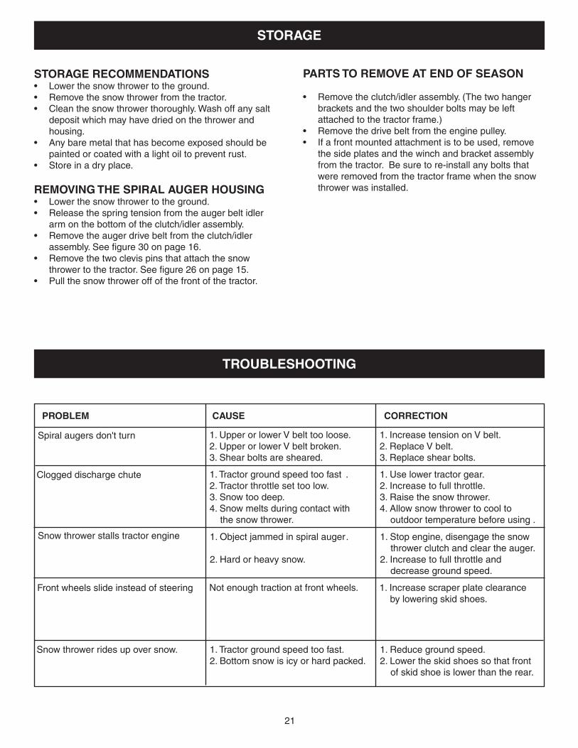
• Removethedrivebeltfromtheenginepulley.• Ifafrontmountedattachmentistobeused,removethesideplatesandthewinchandbracketassemblyfromthetractor.Besuretore-installanyboltsthatwereremovedfromthetractorframewhenthesnowthrower was installed.
STORAGE RECOMMENDATIONS• Lowerthesnowthrowertotheground.• Removethesnowthrowerfromthetractor.• Cleanthesnowthrowerthoroughly.Washoffanysaltdepositwhichmayhavedriedonthethrowerandhousing.
• Anybaremetalthathasbecomeexposedshouldbepainted or coated with a light oil to prevent rust.
• Storeinadryplace.
REMOVING THE SPIRAL AUGER HOUSING• Lowerthesnowthrowertotheground.• Releasethespringtensionfromtheaugerbeltidlerarmonthebottomoftheclutch/idlerassembly.
• Removetheaugerdrivebeltfromtheclutch/idlerassembly.Seefigure30onpage16.
• Removethetwoclevispinsthatattachthesnowthrowertothetractor.Seefigure26onpage15.
• Pullthesnowthroweroffofthefrontofthetractor.
CAUSEPROBLEM CORRECTION
Clogged discharge chute
Spiralaugersdon'tturn
Snow thrower stalls tractor engine
TROUBLESHOOTING
STORAGE
1.UpperorlowerVbelttooloose. 1.IncreasetensiononVbelt.2.UpperorlowerVbeltbroken. 2.ReplaceVbelt.3.Shearboltsaresheared. 3.Replaceshearbolts.
1. Tractor ground speed too fast . 1. Use lower tractor gear.2. Tractor throttle set too low. 2. Increase to full throttle.3. Snow too deep. 3. Raise the snow thrower.4.Snowmeltsduringcontactwith 4.Allowsnowthrowertocooltothesnowthrower. outdoortemperaturebeforeusing.
Front wheels slide instead of steering
Snow thrower rides up over snow.
1.Objectjammedinspiralauger. 1.Stopengine,disengagethesnow thrower clutch and clear the auger.
2. Hard or heavy snow. 2. Increase to full throttle and decrease ground speed.
Not enough traction at front wheels. 1. Increase scraper plate clearance byloweringskidshoes.
1. Tractor ground speed too fast. 1. Reduce ground speed.2.Bottomsnowisicyorhardpacked. 2.Lowertheskidshoessothatfront ofskidshoeislowerthantherear.
22
PARTS
REPAIR PARTS FOR MODEL 45-0491 50" SNOW THROWER
10
11
16
17
18
19
20
21
22 4548
21
2327
45
46
24
25
484526
26
28
29 30
3
9
4
2
87
5
6
14
14
15
12
37
4548
56
48 60
55
55
40
40
5046
38
44
31
1
37
4548 34
2545
57
45
45
3548
4548
3848
45
515339
4947
43
32
5233
4947
42
36
4860
43
34
50
41
13
15
32
47
38
48
54
5859
23
REPAIR PARTS FOR MODEL 45-0491 50" SNOW THROWER
REF PART NO QTY DESCRIPTION1 731-0921 1 Chute, Upper2 731-1300C 1 Chute, Lower3 731-1379A 1 Chute Adapter4 731-0851A 3 Chute Keeper5 784-5594 1 Bracket,Cable6 731-1313C 1 Guide,Cable7 24394 1 Bracket,ChuteAnti-rotation8 1643-60 1 Plastic Cap9 705-5226 1 ChuteReinforcement10 65685 1 SpiralAssembly,L.H.11 65684 1 SpiralAssembly,R.H.12 784-5618 2 Housing, Bearing13 47615 2 Bearing, Flange14 43009 6 Washer, .785" x 1.57" x .057"15 741-0493A 4 Bearing, Split, 3/4"16 25942 1 Shaft,AugerGearbox17 71464 1 GearAssembly18 25937 1 CenterBrace,Gearbox19 63768 1 ImpellerAssembly20 65683 1 HousingAssembly21 24279 2 SkidShoe22 25940 1 Scraper Plate23 24816 1 Cover, Belt24 27280 1 Bracket,Idler25 24466 2 Bracket,DownStop26 47044 2 Pulley, V Type 4"27 24280 1 SupportTubeBracket28 47026 1 Pulley, V Type29 05931 1 Housing, Bearing30 741-0309 1 Bearing, Ball31 43661 6 Hex Bolt, 1/4-20 x 1"
REF PART NO QTY DESCRIPTION32 44950 4 Carriage Bolt, 1/4-20 x 3/4"33 47630 6 Bolt, Self-Tap 5/16" x 3/4"34 43182 3 Hex Bolt, 5/16-18 x 3/4"35 43840 2 Hex Bolt, 5/16-18 x 1-1/4"36 43085 1 Hex Bolt, 5/16-18 x 1-1/2"37 710-0890A 2 Bolt, Shear 5/16-18 x 1-1/2"38 44326 15 Carriage Bolt, 5/16-18 x 1"39 44377 1 Hex Bolt, 3/8-24 x 1" 40 41576 2 Hex Bolt, 3/8-16 x 1-3/4"41 48106 2 Bolt, Shoulder42 710-0896 1 Screw, 1/4-14 x 5/8"43 47189 4 HexNut,1/4-20Nylock44 47598 6 HexLockNut,1/4"Flanged45 47810 30 HexNut,5/16-18Nylock46 HA21362 4 HexNut,3/8-16Nylock47 43088 10 Washer, 1/4"48 43081 28 Washer, 5/16" Std. Wrt.49 48015 4 Washer, Nylon50 43070 2 Washer, 3/8"51 736-0247 1 Washer,52 43086 6 LockWasher,5/16"53 43003 1 Washer,Lock3/8"54 750-0437 1 Bushing55 711-0242 2 Spacer56 715-0114 2 Spiral Pin, 1/4" x 1-1/2" Lg.57 HA20185 1 #61 Woodruff Key58 746-0929 1 Cable,ChuteControlWithClip59 746-0928 1 Cable,ChuteControl60 43064 2 HexLockNut,5/16-18
42432 1 Owner'sManual
24
REPAIR PARTS FOR MODEL 45-0491 50" SNOW THROWER
1
2
2
3
34
4
5
6
66
6
66
8
88
8
9
10
10
10
10
10
11 12
12
13
13
14
14
15
15
16
17
17
18
18
19
19
2021
21
22
23
24
25
25
26
27
28
30
30
31
32
44
40
6349 53
52
40 4041
4245
3846
47
69
43
43
4850
51
54
55
56
64
63
7071
63
63
63
63
66
6768
62
62
62
39
34
34
29
33
33
3637
3537
57
58
59
6261
61
59
5365
65
708
72
30
72
30
7
74
73
7576
6060
25
REF PART NO QTY DESCRIPTION1 67620 1 LiftShaftAssembly2 710-0865 2 Hex Bolt, 1/2-13 x 1"3 710-0367 2 Hex Bolt, 5/8-11 x 1-1/2"4 711-0332 2 Pin,BracketLift5 712-0261 1 Nut,NylockHex5/8-116 43262 6 Nut,HexLock1/2-137 47134 1 Pin, Hair Cotter 5/64"8 142 4 Pin, Cotter 1/8" x 3/4"9 43093 1 Pin, Cotter 1/8" x 1-1/2"10 R19171616 5 Washer, 17/32" x 1"11 43350 6 Carriage Bolt, 3/8-16 x 1"12 741-0192 2 Bearing, Flange With Flats13 783-0380 2 Link,15.80"Long14 783-0381 2 Link,11.75"Long15 67598 2 LiftLink16 24311 1 Rod, Spacer17 47599 2 HexBolt,5/16-18x1"(Locking)18 43086 2 LockWasher,5/16"19 24807 2 Lift Trunnion20 27388 1 Bracket,StopSwitchMounting21 42553 2 Switch22 67614 1 LiftStopAssembly23 67628 1 Bracket,WinchMounting24 42570 1 Winch25 47788 2 Reflector,Rear26 27400 1 Cover,Cable27 HA9411666 1 Screw, 10-16 x 1/2"28 43063 2 Hex Bolt 5/16-18 x 1"29 47631 1 Bolt, Hex 3/8-16 x 1" Self Thd.30 43343 4 Pin, Haircotter #4 (1/8")31 25678 1 Plate, Side (R.H.)32 25679 1 Plate, Side (L.H.)33 43346 4 Bolt, Slotted Head 10-32 X 5/8"34 47171 4 Nut,NylockHex10-3235 HA20186 1 Spring, Idler36 24564 1 Washer, Special37 48714 2 Nut,NylockHexJam5/8-1138 47027 1 Tube,CrankRodSupport
REF PART NO QTY DESCRIPTION39 24393 1 Bracket,ChuteCrank40 741-0475 3 Bushing, 3/8" Plastic41 703-2735A 1 Bracket,ChuteCrank42 720-0201A 1 Knob,Crank43 44917 2 Palnut, 3/8"44 43070 2 Washer, 3/8"45 63579 1 Assembly,ChuteCrankRod46 784-5604A 1 Handle, Chute Tilt47 720-04039 1 Knob48 603-0302 1 Assembly,ChuteTiltBracket49 731-1313C 1 Guide,Cable50 746-0929 1 Cable,ChuteControlwithClip51 746-0928 1 Cable,ChuteControl52 43064 2 Nut,HexLock5/16-1853 43081 3 Washer, 5/16"54 24285 1 Plate, Mounting (L.H.)55 24284 1 Plate, Mounting (R.H.)56 43601 1 Washer, 1.59" x 1.032" x .060"57 65367 1 HangerBracketAssembly,L.H.58 65450 1 HangerBracketAssembly,R.H.59 46730 2 Bolt, Hex 5/16-18 x 3/4" Self Thd.60 726-0178 9 Tie, Nylon61 49933 2 Shoulder Bolt, Round Head62 47572 10 Nut,FlangedLock3/8-1663 47810 12 Nut,NylockHex5/16-1864 R19172410 4 Washer, 1/2"65 44326 4 Carriage Bolt, 5/16-18 x 1"66 48106 2 Bolt, Shoulder67 44695 2 Washer, Bowed68 43682 2 Carriage Bolt, 5/16-18 x 1-1/4"69 44215 2 Carriage Bolt, 5/16-18 x 1-3/4"70 HA21362 2 HexNut,3/8-16Nylock71 43182 2 Bolt, Hex 5/16-18 x 3/472 43038 2 Pin,PivotLock73 42554 1 Wire Harness74 42555 1 Wire Harness Extension75 67714 1 SwitchMountingAssembly76 HA23761 1 CableClip
REPAIR PARTS FOR MODEL 45-0491 50" SNOW THROWER
26
REPAIR PARTS FOR MODEL 45-0491 50" SNOW THROWER
REF PART NO QTY DESCRIPTION1 43080 1 Carriage Bolt, 5/16-18 x 3/4"2 47810 12 HexNut,5/16-18Nylock3 43083 2 Hex Nut, 5/16-184 43086 4 LockWasher,5/16"5 43081 12 Washer, 5/16" Std. Wrt.6 26943 1 Frame,ClutchandPulley7 63904 1 IdlerArmAssembly8 24286 1 Spacer, Pivot
REF PART NO QTY DESCRIPTION9 63762 1 IdlerBracketAssembly10 43015 1 Hex Nut, 3/8-1611 46981 1 Pulley, V Type 9"12 43082 8 Nut,HexLock,3/8-1613 46982 1 Pulley, V Type 5-1/2"14 738-0680 1 Shaft15 750-0456 1 Spacer16 750-0660 1 Spacer17 43003 6 LockWasher,3/8"18 714-0161 2 Key19 741-0919 2 Bearing, Ball20 08253B 1 Housing, Bearing21 15296A 1 Housing, Open Bearing22 14088B 1 Spacer, Spindle23 44377 2 Hex Bolt, 3/8-24 x 1"24 736-0247 2 Washer25 43063 3 Hex Bolt, 5/16-18 x 1"26 46989 1 Belt, V Type Drive (55")
48138 1 Belt, V Type Drive (56")27 47846 1 Belt, V Type Auger28 47044 1 Pulley, V Type 4"29 47025 1 Hex Bolt, 5/16-18 x 3-1/2"30 43432 1 Hex Bolt, 3/8-16 x 2-1/2"31 43054 3 Hex Bolt, 3/8-16 x 2"32 24571 1 Spacer33 24472 1 Spacer, Pivot34 43070 8 Washer, 3/8"35 46959 1 Spring36 46963 2 Chain37 43055 1 Pin, Hair Cotter, 3/32"38 23727 1 Spacer39 43088 1 Washer, 1/4"40 43343 2 Pin, Hair Cotter #4 (1/8")41 47134 1 Pin, Hair Cotter 5/64"42 46938 1 Hex Bolt, 3/8-16 x 3-1/4"43 25780 1 Spacer44 47620 1 Spring45 47607 1 Spring, Torsion46 23625 1 Spacer47 43509 1 Hex Bolt, 3/8-16 x 2-3/4" Lg.48 47605 1 Washer, Flat 3/8"49 24558 1 CableBracket50 49870 1 Hex Bolt, 1/4-20 x 2-1/2"51 43178 2 Hex Nut, 1/4-2052 43177 1 LockWasher,1/4"53 48883 3 Pulley, Flat 3-5/8" 54 25728 2 RearPulleyFrameBracket55 43182 4 Hex Bolt, 5/16-18 x 3/4"56 43063 4 Hex Bolt, 5/16-18 x 1"57 27016 2 FrontPulleyFrameBracket
27
SLOPE GUIDE(Keep this sheet in a safe place for future reference.)
Use this guide to determine if a slope is safe for the operation of your tractor and snow thrower. Refer also to the instructions in your vehicle owners manual.
CA
UT
ION
:
DO
N
OT
O
PE
RA
TE
YO
UR
TR
AC
TO
R
AN
D
SN
OW
T
HR
OW
ER
ON
A S
LO
PE
IN E
XC
ES
S O
F 10 D
EG
RE
ES
. BE
SU
RE
O
F Y
OU
R T
RA
CT
OR
'S T
OW
ING
AN
D B
RA
KIN
G C
AP
AB
ILIT
IES
B
EF
OR
E O
PE
RA
TIN
G O
N A
SL
OP
E. A
VO
ID A
NY
SU
DD
EN
TU
RN
S O
R
MA
NE
UV
ER
S W
HIL
E O
N A
SL
OP
E.
A P
OW
ER
PO
LE
A C
OR
NE
R O
F A
BU
ILD
ING
OR
A F
EN
CE
PO
ST
FOLD
ALO
NG
DO
TTED
LINE
, RE
PR
ES
EN
TING
A 10 D
EG
RE
E S
LOP
E
SIG
HT
AN
D H
OL
D T
HIS
LE
VE
L W
ITH
A V
ER
TIC
AL
TR
EE
the fastest way to purchase parts www.speedepart.com
REPAIR PARTSAgri-Fab,Inc.
809SouthHamiltonSullivan, IL. 61951
217-728-8388www.agri-fab.com
©2003Agri-Fab,Inc.
Thisdocument(ormanual)isprotectedundertheU.S.CopyrightLawsandthecopyrightlawsofforeigncountries,pursuanttotheUniversalCopyrightConventionandtheBerneconvention.Nopartofthisdocumentmaybereproducedortransmittedinanyformorbyanymeans,electronicormechanical,includingphotocopyingorrecording,orbyanyinformationstorageorretrievalsystem,withouttheexpresswrittenpermissionofAgri-Fab,Inc.Unauthorizedusesand/orreproductionsofthismanualwillsubjectsuchunauthorizedusertocivilandcriminalpenaltiesasprovidedbytheUnitedStates Copyright Laws.
??????