52
Owner’s Manual & Operating Instructions WPT 480/P, WPR 600/P, WPT 720/P National Vacuum Equipment, Inc.
Owner’s Manual&
Operating InstructionsWPT 480/P, WPR 600/P, WPT 720/P
National Vacuum Equipment, Inc.

2 | WPT Series www.natvac.com | 800.253.5500
© 2011 National Vacuum Equipment, Inc.Revision: 3 (Release) March 2011
No part of this manual may be reproduced without the written permission of National Vacuum Equipment, Inc.
WPT 480/PWPT 600/PWPT 720/P
Owner’s Record Date of Purchase: _________________________ Purchased from: __________________________ Serial Number: ____________________________
WPT Series | 3www.natvac.com | 800.253.5500
Contents
IntroductionAbout National Vacuum Equipment, Inc. 5
Limited WarrantyWarranty 7
Warranty Procedures 9
The WPT/P Series PumpsPump Specifications 11
Performance 12System requirements 13
Operating InstructionsInstallation 15Automatic oil pump 16
Adjusting the automatic oil pump 16
Recommended lubrication 17Normal operation for liquid cooled pumps: 18
Maintenance 19
Determining the rotation of the pump 19
WPT Pump Cooling SystemWPT Pump Cooling System 20
TroubleshootingPump overheats 21
Too much oil use 21
Pump doesn’t turn 22No vacuum or pressure in tank 22
Pump RebuildingComplete rebuild 23
Table of Contents continues on next page.

4 | WPT Series www.natvac.com | 800.253.5500
Parts List - WPT Series PumpsParts Diagram 34Parts List 35
Four-Way Valve AssemblyFour-Way Valve Diagram and Parts List 37
Lubrication/Cooling SystemsWPT 480/P-WPT 600/P-WPT 720/P 38
WPT 480/PW-WPT 600/PW-WPT 720/PW 39Lubrication/Cooling System Parts 40
Automatic Oil Pumps3-4 43
Index

WPT Series | 5www.natvac.com | 800.253.5500
Introduction
General Information
About National Vacuum Equipment, Inc.
Congratulations! You now own a quality vacuum/pressure
pump exclusively distributed in North America by National
Vacuum Equipment, Inc. You have not only acquired asuperior piece of equipment from a qualified dealer, you
have hired a team of vacuum experts. We stand ready to
work with your dealer to answer your questions andprovide you with the information necessary to keep your
equipment in peak working condition.
Thank you for using National Vacuum Equipment.
OUR MISSION:
We are dedicated to the manufacture and wholesaledistribution of quality vacuum system products at a
reasonable price, on a timely basis. We are a “one-stop
shop” for manufacturers and distributors of vacuumequipment.
NVENVE

6 | WPT Series www.natvac.com | 800.253.5500
OUR HISTORY:
National Vacuum Equipment, Inc. was founded in 1980 byBruce Luoma. The Company started as a retailer of vacuum
pumps. Soon after it started, the Company secured the
rights to exclusive distribution of the Battioni vacuumpumps in North America. This helped the Company to
evolve into its current status as a wholesale supplier.
To reach the goal of becoming a full service supplier of
vacuum system components, the Company began
fabricating its own line of componentry, purchased anddeveloped its own line of vacuum pumps, and began
purchasing for resale various valves and accessories.
Today, NVE has full service machine and fabrication shops
complete with CNC-controlled production equipmentdesigned for close tolerance work. The company has a
highly trained staff all of whom are dedicated to quality.
WPT Series | 7www.natvac.com | 800.253.5500
Limited Warranty
WPT 480/PWPT 600/PWPT 720/P
National Vacuum Equipment, Inc.
guarantees that the product it provides is free of
manufacturer’s defects, including materials and
workmanship. Properly installed and maintained
product is warranted for a period of one (1) year
subject to the following conditions:
1. A properly completed warranty registration card
must be received by us within 30 days of sale to
end user for pump sales to be consideredwarrantable. All pumps received for warranty
consideration must retain the original NVE serial
number tag.
2. The one (1) year period shall begin the day the
product is shipped from our warehouse, unless we
are provided with an authentic copy of the originalresale invoice, in which case the one (1) year
period shall begin at such invoice date.
3. The covered product must be used in anapplication for which it was intended. We do not
recommend our product for particular uses or
applications.
National Vacuum Equipment, Inc.
Guarantees that the product it provides is free of manufacturer’s defects, including materials and workmanship. Properly installed and maintained product is warranted for a period of one (1) year subject to the following conditions:
1. A properly completed warranty registration card must be received by us within 30 days of sale to end user for pump sales to be considered warrantable. All pumps received for warranty consideration must retain the original NVE serial number tag.
2. The one (1) year period shall begin the day the product is shipped from our warehouse, unless we are provided with an authentic copy of the original resale invoice, in which case the one (1) year period shall begin at such invoice date.
3. The covered product must be used in an application for which it was intended. We do not recommend our product for particular uses or applications.
4. Vane breakage, or damage caused by vane breakage, is not war-rantable.
5. Damage caused by improper use or lack of proper maintenance is not warrantable.

8 | WPT Series www.natvac.com | 800.253.5500
6. Manufacturer’s liability under this or any other warranty, whether express or implied, is limited to repair of or, at the manufacturer’s option, replacement of parts which are shown to have been defective when shipped
7. Manufacturer’s liability shall not be enforceable for any product until National Vacuum Equipment, Inc. has been paid in full for such product.
8. Except to the extent expressly stated herein, manufac-turer’s liability for incidental and consequential damage is hereby excluded to the full extent permitted by law.
9. Manufacturer’s liability as stated herin cannot be altered except in writing signed by an officer of National Vacuum Equipment, Inc.
10. Certain products provided by National Vacuum Equipment, Inc. are covered by their respective manufacturer’s warran-ties (e.g., engines used in the NVE engine drive packages). These products are not covered by the National Vacuum Equipment, Inc. Manufacturer’s Warranty.
11. Final assemblers responsibility. NVE goes to great lengths to insure the quality and proper functionality of the products it supplies. Many products we supply are purchased for resale or are impossible or impractical to test prior to the in-stallation of the item in a vacuum system. It is therefore the responsibility of the final assembler to thoroughly test the vacuum system and components supplied to the assembler by NVE prior to the delivery of the final product to the end user.
12. Not responsible for pump coupling tightness or alignment. Customer needs to inspect periodically to ensure proper alignment and to check tightness of set screws.
WPT Series | 9www.natvac.com | 800.253.5500
Any items found to be defective after delivery to the end user that should have been discovered prior to deliver will qualify replace-ment of the defective part only with absolutely no compensation for outside labor or travel expenses. Any subsequent damage to other components caused by the defective part will be the sole responsibility of the assembler.____________________________________________________Warranty Procedures
Should a potential warranty situation arise, the following procedures must be followed:
• Contact your dealer or NVE immediately upon the occurrence of the event and within the warranty period.
• Customer must receive a return goods authorization (RGA) before returning product.
• All serial-numbered products must retain the NVE serial number tag to be qualified for warranty.
• Product must be returned to NVE intact for inspection before warranty will be honored.
• Product must be returned to NVE freight prepaid in the most economical way.
• Credit will be issued for material found to be defective upon our inspection, based upon prices at the time of purchase.

10 | WPT Series www.natvac.com | 800.253.5500

WPT Series | 11www.natvac.com | 800.253.5500
The WPT Series Pumps
Model-Specific Informationfor theWPT 480/PWPT 600/PWPT 720/P
WPT Series Pump Specifications
Model Number 480 600 720RPM Range 600-1250 600-1250 600-1250Max. Air Flow-CFM 300 385 467Max. Continuous Vacuum 25 25 25Max. Intermittent Vacuum 28 28 28Max. Continuous Pressure 28 25 25Max. Intermittent Pressure 30 30 30Pump Drive Rotation CW/CCW CW/CCW CW/CCWPorting Size 3 inch 3 inch 3 inchManifold With Four Way Valve Std Std StdEnd Thrust Protection Std Std StdBearings Sealed From Pump Interior Std Std StdAnti-Spin Check Valve Std Std StdAutomatic Lubrication System Std-2 pt Std - 3 pt Std-4ptOil Tank Capacity-Quarts 4 5 6Net Weight 547 lbs 660 lbs 720 lbs
WPT 720

12 | WPT Series www.natvac.com | 800.253.5500
Performance
WPT 600/P PERFORMANCE
WPT 720/P PERFORMANCE
PRESSURE PSI VACUUM – INCHES OF MERCURY
RPM
1250
1000
800
HP
CFM
HP
CFM
H.P
CFM
25
36
216
28
160
23
116
20
30
225
24
168
19
127
15
25
237
19
182
15
136
10
19
254
14
197
11
150
5
13
274
10
214
7
165
0
8
300
6
237
4
188
3
9
293
7
232
5
184
6
10
286
8
223
5
174
9
11
277
9
214
6
166
12
12
271
10
203
7
160
15
14
260
11
188
8
156
18
15
245
12
174
9
152
21
16
228
13
160
10
146
24
18
185
14
130
11
120
27
19
109
15
80
12
70
WPT 480/P PERFORMANCE
PRESSURE PSI VACUUM – INCHES OF MERCURY
RPM
1250
1000
800
HP
CFM
HP
CFM
H.P
CFM
25
51
312
39
235
31
176
20
42
318
32
246
26
191
15
35
331
27
256
20
200
10
27
346
20
270
16
211
5
19
361
15
285
11
226
0
12
385
9
323
6
247
3
13
380
10
308
7
244
6
15
374
11
297
8
235
9
16
364
12
288
9
226
12
18
355
13
285
10
214
15
19
340
14
267
11
198
18
21
324
16
250
12
182
21
22
303
17
232
13
158
24
24
272
18
203
15
117
27
26
193
20
144
16
85
PRESSURE PSI VACUUM – INCHES OF MERCURY
RPM
1250
1000
800
HP
CFM
HP
CFM
H.P
CFM
25
57
388
47
300
37
225
20
49
400
40
315
31
240
15
40
414
32
330
26
255
10
32
427
24
340
20
270
5
23
448
17
390
14
290
0
15
467
11
380
8
310
3
16
464
12
370
9
305
6
18
459
14
365
10
300
9
20
446
16
360
12
290
12
22
434
18
345
14
280
15
24
427
20
340
15
270
18
26
409
21
320
16
255
21
28
390
22
300
18
235
24
30
351
24
265
19
205
27
31
280
26
210
20
140
WPT Series | 13www.natvac.com | 800.253.5500
System requirements
High quality components
• The pump body and rotor are constructed of castiron with free sliding vanes made of special
nonmetallic, heat resistant material.
• Vanes wear evenly because tips always remain incontact with the wall surface.
• For maximum life and proper performance we
recommend the use of our compatiblecomponents, Portal Shutoff F-800-LC-8-3 and
Moisture Trap
F-901B.

14 | WPT Series www.natvac.com | 800.253.5500

WPT Series | 15www.natvac.com | 800.253.5500
Operating Instructions
WPT 480/PWPT 600/PWPT 720/P
Installation
• Check pump rotation. Standard rotation isclockwise unless otherwise marked. See
Determining the Rotation of Pump.
• Recommended operating speed is 850 to 1000rpm.
• Pump should always be mounted in a level,horizontal position on a firm, flat surface.
• Grade 5 bolts should be used in installation. It is
important to use flat washers and lock washers.
• We recommend the use of oil resistant hose on
both the inlet and outlet sides of the pump. If
using direct drive system, always use a flexiblecoupling. We recommend the use of Woods Sure
Flex Couplers.
• The drive mechanism should be suitable for thehorsepower required to drive the pump.
• Because WPT pumps are fitted with roller bearings
the rotor is able to float from side to side. It isimportant during initial setup that no undue
pressure is put on the rotor that would cause the

16 | WPT Series www.natvac.com | 800.253.5500
• Cooling system: normal operating temperature is
140°F - 175°F. Maximum temperature is 200°F.
• Coolant lines should be assembled as follows:
a. (Cool water) From coolant source to the
circulating pump to the fitting on the top of therear endplate back to coolant source.
b. After filling with coolant, run the circulating
pump and recheck the coolant level.
c. After running for several minutes, loosen the
thermometer slightly to allow any air trapped in
the pump to escape. Then retighten thethermometer.
• A 2” pressure relief valve and a 1½” vacuum relief
valve have been shipped with your pump and needto be mounted on the top of the pump.
Automatic oil pump
• The automatic oil pumps are set at the factory
during pump testing and should require no further
adjustment during pump installation.
• The pumps are adjusted to one drop every two
seconds per outlet. This oil rate equals 2.7 fluid
oz. per hour.
Adjusting the automatic oil pump
The automatic oil pump is a metered piston-type pump. If you wish to adjust the pump, please follow these instruc-
tions:
Adjusting the oil rate
Oil flow is changed by adjusting the length of the stroke ofthe piston.

WPT Series | 17www.natvac.com | 800.253.5500
1. To adjust the oil rate, remove cap
#P16. Under this cap you will find a jamnut #P15 and adjusting screw #P11.
2. To adjust oil rate loosen jam nut
and turn adjusting screw clockwise toreduce oil flow or counterclockwise to
increase oil flow.
3. When making adjustments do soone turn of the screw at a time and test
before making further adjustments.
4. Be careful to not turn adjustingscrew too far counterclockwise as you
may disengage the gears and strip them
out.
Testing flow rate after adjustment
1. Observe oil drip rate in oil view meter or oil line to
ensure adequate lubrication.
2. Adjustments should be done gradually so as not tostarve the vacuum pump of oil.
Recommended lubrication
We recommend that turbine grade oil be used in all our pumps.Turbine oil is more highly refined than motor oil and is much lesslikely to create carbon. Turbine oil is available from your local oildistributor. Below is a list of acceptable oils.
• Penzoil Penzabell 68 T.O.
• Shell Turbo 68
• Mobil D.T.E. Heavy – Medium
Recommended Lubricant
• Werecommendthatturbineoilbeusedinourpumps.Turbineoilismuchmoreresistanttobreakdownduetoheatthannor-malmotoroil,therebyavoidingtheproblemsassociatedwithmotoroilsuchaslacqueringandexcessivewear.
•Acceptableoilsinclude:1. *NVEISO68Oil2. PenzoilPenzabell68T.O.3. ShellTurbo684. MobilD.T.E.Heavy-Medium5. TexacoRegalR&O68
*NVEISO68OilisourrecommendedpumpoilfortheChallengerseriesvacuumpumps.ChallengerVacuumPumpOilissoldbythecase,six1galloncontainersofoilpercase.

18 | WPT Series www.natvac.com | 800.253.5500
• Texaco Regal R.N.O. 68
Normal operation for liquid cooled pumps:
1. Check oil reservoir daily and fill as required.
2. When the pump is in operation, check the oiler to
insure flow of oil to the pump.
3. Do not operate the pump faster than recommended
rpm.
4. If an in-line 12 volt circulating pump is used,make sure it is turned on.
5. Always monitor the water temperature gauge.
6. To operate the suction valve on top of the pump,move the handle in the appropriate direction for
either vacuum or pressure. Center it for neutral.
7. We recommend periodic cleaning of your pump.To do this, remove the suction line from the pump.
Move the suction valve to neutral, run the pump atan idle, and pour into the pump intake one pint of
diesel fuel. Allow the pump to run a short time,
move the suction valve to vacuum, and blow ourthe diesel fuel and dirt. Move the suction valve to
neutral and pour in a pint of oil. Allow the pump to
run a short time before reassembling.
8. We recommend checking vane wear every twelve
months. A new vane is nearly flush with the rotor.
Measure the wear and if is over 1/4" werecommendrecommend replacing vanes. It’s good to always keep
a spare set of vanes on hand for emergencies.

WPT Series | 19www.natvac.com | 800.253.5500
replacing vanes. It’s good to always keep a spare set of
vanes on hand for emergencies.
Maintenance
• Oil should be supplied to pump at a rate of 1 drop
every 2 seconds.
• Average usage of oil is approximately 1-2 qts. per
40 hours, depending on operation.
• Normal vane life is approximately 2000 hours;however, this will vary greatly with temperature,
material being pumped, and proper maintenance.
Occasionally, liquid and dirt may enter the pump,causing vanes to stick in the rotor slots, along with
excessive vane and housing wear. When this
occurs, you must clean the inside of the pump.
Determining the rotation of the pump
As one faces the drive end of the pump:
• If the oiler is on the right, the pump shaft turnsclockwise.

20 | WPT Series www.natvac.com | 800.253.5500
• If the oiler is on the left, the pump shaft turns
counterclockwise.
WPT Pump Cooling System
• Because vacuum pumps generate large amounts of
heat during operation, consideration of pump
cooling is very important.
• If you are installing a liquid cooled pump, follow
the pump manufacturers recommendations for
pump cooling.
• Make sure all guards are in place.
• With liquid cooled pumps it is a good idea to
install shutoff valves in the water lines.

WPT Series | 21www.natvac.com | 800.253.5500
• Before operating the pump, bleed any air from the
system by loosening the thermometer.
Troubleshooting
WPT 480/PWPT 600/PWPT 720/P
Pump overheats
• Inlet water temperature too high
• Inadequate water flow
• No oil in pump
• Oil adjustment set too lean
• RPM too fast
• Prolonged operation
Too much oil use
• Oil adjustment set too rich
• Oil seals defective
• Cracked pump body
Pump doesn’t turn
• Broken vane
• Frozen
• Pump endplate bolts too tight
• Faulty PTO or drive set up
No vacuum or pressure in tank
• Suction valve in neutral
• Defective seal or vanes
• Pump not driven fast enough
• Check valve or suction line clogged

22 | WPT Series www.natvac.com | 800.253.5500
• Cracked pump body
Pump doesn’t turn
• Broken vane
• Frozen
• Pump endplate bolts too tight
• Faulty PTO or drive set up
No vacuum or pressure in tank
• Suction valve in neutral
• Defective seal or vanes
• Pump not driven fast enough
• Check valve or suction line clogged
• Leak in tank or fittings
Pump Rebuilding
WPT 480/PWPT 600/PWPT 720/P
Please read these instructions completely beforeattempting repair.
1. Remove the drain plug on the
bottom of the rear endplate.
2. Remove the oil lines from the oil
pump.
The oil lines are self-locking.
Complete rebuild

WPT Series | 23www.natvac.com | 800.253.5500
• Leak in tank or fittings
Pump Rebuilding
WPT 480/PWPT 600/PWPT 720/P
Please read these instructions completely beforeattempting repair.
1. Remove the drain plug on the
bottom of the rear endplate.
2. Remove the oil lines from the oil
pump.
The oil lines are self-locking.
Complete rebuild
24 | WPT Series www.natvac.com | 800.253.5500
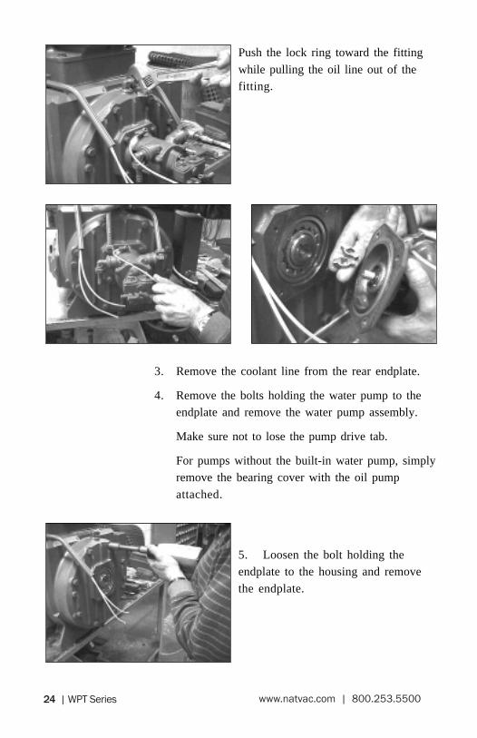
5. Loosen the bolt holding theendplate to the housing and remove
the endplate.
Push the lock ring toward the fitting
while pulling the oil line out of thefitting.
3. Remove the coolant line from the rear endplate.
4. Remove the bolts holding the water pump to theendplate and remove the water pump assembly.
Make sure not to lose the pump drive tab.
For pumps without the built-in water pump, simplyremove the bearing cover with the oil pump
attached.

WPT Series | 25www.natvac.com | 800.253.5500
Note the number of gaskets.
The WPT pumps are equipped with
roller bearings, so no special pullersare required.
Place a pan under the endplate to catch escaping
26 | WPT Series www.natvac.com | 800.253.5500
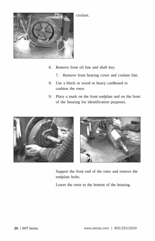
coolant.
6. Remove front oil line and shaft key.
7. Remove front bearing cover and coolant line.
8. Use a block or wood or heavy cardboard to
cushion the rotor.
9. Place a mark on the front endplate and on the frontof the housing for identification purposes.
Support the front end of the rotor and remove the
endplate bolts.
Lower the rotor to the bottom of the housing.

WPT Series | 27www.natvac.com | 800.253.5500
10. Slide the endplate off the rotor
and remove the rotor from thehousing.
Note the number of gaskets.
11. Inspect the housing bore andrenew as necessary.
The pump bore new is 9.840 inches.
The maximum overbore recommendedis .060 inch.
Thoroughly clean the housing and scrape off the old
endplate gaskets.
The side cover gaskets are usually not removed during
a normal rebuild.
12. Thoroughly clean the rotor, paying particularattention to the slots.
Inspect the rotor for nicks orburrs and remove as necessary.
When you are finished the vanes
should slide freely in the slots.
13. Lubricate the housing bore.

28 | WPT Series www.natvac.com | 800.253.5500
Place the cushion used earlier back into the bore and
install the rotor, making sure the long end of therotor is in the proper end of the housing.
14. Remove the bearings and seals.
If your intention is to reuse the bearings, carefullydrive the bearings out using a small hammer and
punch.
Work the bearing out slowly. They can be easilydamaged.
Thoroughly clean the endplateand scrape off any remaining gasket
material.
Make sure the oil passagethrough the endplate is clear.
WPT Series | 29www.natvac.com | 800.253.5500
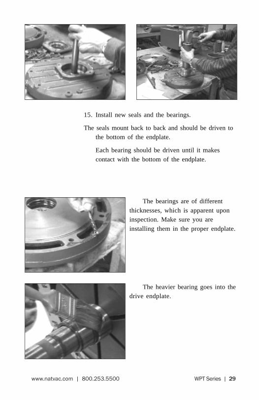
15. Install new seals and the bearings.
The seals mount back to back and should be driven tothe bottom of the endplate.
Each bearing should be driven until it makes
contact with the bottom of the endplate.
The bearings are of different
thicknesses, which is apparent uponinspection. Make sure you are
installing them in the proper endplate.
The heavier bearing goes into thedrive endplate.

30 | WPT Series www.natvac.com | 800.253.5500
16. Apply a hardening gasket sealer
to the front plate and to the end of thepump housing.
17. Lubricate the front seal sleeve,
seals and bearing.
18. Slide the rotor into the housing,
making sure the input shaft isprotruding from the drive end of the
housing.
Install the cushion used earlier in the
non-drive end.
19. Install the same number ofendplate gaskets on the housing and
slide the drive endplate onto the drive
end of the rotor.

WPT Series | 31www.natvac.com | 800.253.5500
20. Raise the rotor and the endplate
assembly up and install the endplatebolts.
21. Remove the cushion previously
used from the housing and install thevanes.
Make sure the round end is facing out
of the rotor.
22. Apply sealer to the rear endplate
and housing and install the proper
number of gaskets on the rear of thehousing.
Important: Make sure the water
passage hole on the gasket is lined upwith the water passage hole in the housing.
23. Slide the rear endplate on to the rotor.
Raise the assembly up and install the endplate bolts.
When the endplate is nearly touchingthe housing, pry the assembly up to

32 | WPT Series www.natvac.com | 800.253.5500
set the seal gap.
Loosen the front endplate bolts and
pry the front endplate while tighteningthe bolts.
This is particularly important if
you have honed or bored yourhousing.
24. Seat the bearings, front and rear.
25. You should now be able to turn
the pump by hand.
26. Clean the front bearing cover and
replace the seal.
Lubricate the seal and rotor.
Use sealer on the gasket and installthe bearing cover on the front
endplate.
27. Using an oil squirt can, pump sixsquirts into the bearing cavity through
the oil fitting.
Reinstall the oil line.

WPT Series | 33www.natvac.com | 800.253.5500
28. Install the drive tabs in the rear of the rotor and
install the water pump assembly, using sealer onthe gasket.
Make sure the water pump drive lines up with the tabs.
During this operation, you must also position the waterline in the fitting at the top of the endplate.
29. Reinstall the oil lines at the oil pump.
Make sure the lines going to the
bearings are attached to the same sideof the oil pump to ensure equal oiling
to each bearing.
If the oil lines leak, trim the ends
with a razor knife to get a clean end.
Insert the line into the fitting and pullback to seat the line on to the fitting.
Tighten the coolant fitting to the endplate and the
water pump.
30. Reinstall the front coolant line.
31. The pump is now ready to run.
Start the pump and turn as slowly as possible.

34 | WPT Series www.natvac.com | 800.253.5500
Nat
ion
al V
acu
um
Eq
uip
men
t, In
c.P
arts
Dia
gra
m
WP
T 4
80/P
WP
T 6
00/P
WP
t 720
/P

WPT Series | 35www.natvac.com | 800.253.5500
Par
t #D
escr
ipti
on
R53
Cov
er -
480
(oi
l)R
53/A
Cov
er -
600
(oi
l)R
53/B
Cov
er -
720
(oi
l)W
1/F
Hou
sing
- 48
0W
P1/F
Hou
sing
- 60
0W
PT1/
FH
ousi
ng -
720
W5/
PR
otor
-48
0/P
WP5
/PR
otor
- 6
00/P
WPT
5/P
Rot
or -
720
/PW
7-4
Van
e 48
0W
7-6
Van
e - 4
80W
P7V
ane
- 600
WPT
7-4
Van
e 72
0W
PT7-
6V
ane
720
W11
Bol
t (m
8x16
)W
13G
aske
tW
17W
ashe
r (10
)W
18/P
Seal
(65x
85x1
0)W
19B
olt (
m8x
20)
Par
t #D
escr
ipti
on
W20
Was
her (
18)
W53
Cov
er -
480
WP5
3C
over
- 6
00W
PT53
Cov
er -
720
W54
Gas
ket -
480
WP5
4G
aske
t - 6
00W
PT54
Gas
ket -
720
W81
/PN
Seal
(45
-62-
10)
W83
/FR
ear E
ndpl
ate
W84
Gas
ket
W85
Bol
t (m
1x70
)W
86B
eari
ng (N
J230
9)W
93B
eari
ng (N
J309
)W
95B
eari
ng C
over
W96
Fron
t End
plat
eW
97K
ey (1
0x8x
80)
W10
2Fr
ost P
lug
W10
3Se
al S
leev
eW
104
Seal
Sle
eve

36 | WPT Series www.natvac.com | 800.253.5500
________________________________________________________________________________________________________________________________________________________________________________________________________________________________________________________________________________________________________________________________________________________________________________________________________________________________________________________________________________________________________________________________________________________________________________________________________________________________________________________________________________________________________________________________________________________________
Notes

WPT Series | 37www.natvac.com | 800.253.5500
Four-Way Valve Assembly
WPT 480 – WPT 600 – WPT 720
Part # Description
W17WasherW20WasherW34Bolt (m.8x25)W40Seal (35-50-7)W74O-RingW774-Way Valve HousingW784-Way Valve CoverW79GasketW80Bolt (m.10x45)W87Air HornW88Flange Clamping

38 | WPT Series www.natvac.com | 800.253.5500
Lu
bri
cati
on
/Co
olin
g S
yste
m
WP
T 4
80/P
– W
PT
600
/P –
WP
T 7
20/P

WPT Series | 39www.natvac.com | 800.253.5500
Lu
bri
cati
on
/Co
olin
g S
yste
m
WP
T 4
80/P
W –
WP
T 6
00/P
W –
WP
T 7
20/P
W

40 | WPT Series www.natvac.com | 800.253.5500
Lu
bri
cati
on
/Co
olin
g S
yste
m
WP
T 4
80 –
WP
T 6
00 –
WP
T 7
20P
art #
Des
crip
tio
n
LW32
D...
......
......
.....
Oil
Pum
p –
480
CW
LW32
S...
......
......
.....
Oil
Pum
p –
480
CC
WLW
32A
D...
......
......
..O
il Pu
mp
– 60
0 C
WLW
32A
S...
......
......
...O
il Pu
mp
– 60
0 C
CW
LW32
BD
......
......
.....
Oil
Pum
p –
720
CW
LW32
BS
......
......
......
Oil
Pum
p –
720
CC
WR
1O
il Pr
otec
tor T
ube
– 48
0R
1/A
Oil
Lin
e Pr
otec
tor T
ube
– 60
0R
1/B
Oil
Lin
e Pr
otec
tor T
ube
– 72
0R
2D
ripp
erR
3Fi
tting
R7
Bra
ss C
oola
nt L
ine
R8
Bol
t (m
6x12
)R
9B
rack
etR
10H
ose
R10
/A...
......
......
......
.Hos
eR
10/B
......
......
......
....H
ose
Par
t #D
escr
ipti
on
R12
Hos
eR
13H
ose
R13
/AH
ose
R15
90°
Fitt
ing
R16
Hos
eR
19W
ashe
rR
20O
il Fi
ll C
apR
23B
rass
Coo
lant
Lin
eR
26K
ey (
m5x
6)R
28R
ing
R30
Bol
tR
31G
aske
tR
32D
Oil
Pum
p –
480
CW
R32
SO
il Pu
mp
– 48
0 C
CW
R32
AD
......
......
......
......
...O
il Pu
mp
– 60
0 C
WR
32A
SO
il Pu
mp
– 60
0 C
CW
R32
BD
......
......
......
......
...O
il Pu
mp
– 72
0 C
WR
32B
SO
il Pu
mp
– 72
0 C
CW
R33
Was
hers
R34
Bol
t (m
6x16
)R
35F
itti
ngR
36F
itti
ngR
37F
itti
ngR
37-1
Fitt
ing
- St
raig
ht

WPT Series | 41www.natvac.com | 800.253.5500
Par
t #D
escr
ipti
on
R38
Bea
ring
(60
002R
S)
R39
Sea
l (1
2x20
x5)
R40
Impe
ller
R43
Bea
ring
(62
01)
R45
Hos
eR
45/A
Hos
eR
45/B
Hos
eR
46B
ushi
ngR
47V
alve
R52
DO
il Ta
nk–
480
CW
R52
SO
il Ta
nk –
480
CC
WR
52A
D...
......
......
......
......
Oil
Tank
– 6
00/7
20 C
WR
52A
SO
il Ta
nk –
600
/720
CC
WR
53C
over
– 4
80 (
Oil)
R53
/AC
over
– 6
00 (
Oil)
R53
/BC
over
– 7
20 (
Oil)
R54
Sigh
t Tub
eR
59Sn
ap R
ing
R60
Sea
l (1
5x26
x7)
R64
O-R
ing
R65
Impe
ller
Cov
erR
66S
pace
r (2
0x28
x2)
R67
Dri
ve T
abR
68Tu
be
Par
t #D
escr
ipti
on
R69
Was
her (
8)R
70B
olt (
m8x
20)
R71
Coo
lant
Tub
eR
72E
lbow
R73
Fil
ter
R74
Was
her (
1/2"
gas
)R
75A
dapt
erR
76W
ashe
r (1/
8" g
as)
R77
Dis
trib
utio
n B
lock
R79
Bol
t (1/
8"x3
0)R
89Sh
aft
R90
Pack
ing
R91
Snap
Rin
gR
92W
ashe
rR
93W
ater
Pum
p H
ousi
ngR
94R
ear B
eari
ng C
over
R10
0O
il L
ine
– Sm
all –
Bul
lkR
101
Oil
Lin
e –
Lar
ge –
Bul
k

42 | WPT Series www.natvac.com | 800.253.5500
________________________________________________________________________________________________________________________________________________________________________________________________________________________________________________________________________________________________________________________________________________________________________________________________________________________________________________________________________________________________________________________________________________________________________________________________________________________________________________________________________________________________________________________________________________________________
Notes
WPT Series | 43www.natvac.com | 800.253.5500
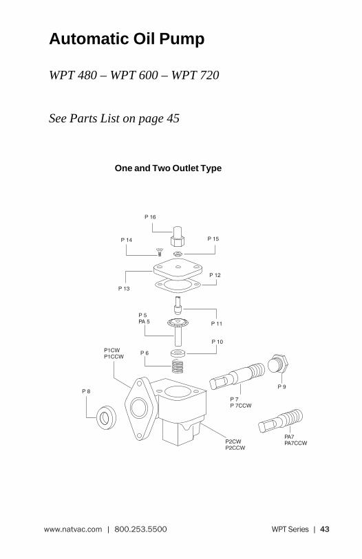
Automatic Oil Pump
WPT 480 – WPT 600 – WPT 720
See Parts List on page 45
One and Two Outlet Type

44 | WPT Series www.natvac.com | 800.253.5500
Automatic Oil Pump
WPT 480 – WPT 600 – WPT 720
See Parts List on page 45
Three and Four Outlet Type

WPT Series | 45www.natvac.com | 800.253.5500
Automatic Oil Pump
WPT 480 – WPT 600 – WPT 720
Oil Pump – Long Shaft (w/o Water Pump)
Part # Description
LW32D Oil Pump – 480 (CW)LW32S Oil Pump – 480 (CCW)LW32AD Oil Pump – 600 (CW)LW32AS Oil Pump – 600 (CCW)LW32BD Oil Pump – 720 (CW)LW32BS Oil Pump – 720 (CCW)
Oil Pump – Short Shaft (w Water Pump)
Part # Description
R32D Oil Pump – 480 (CW)R32S Oil Pump – 480 (CCW)R32AD Oil Pump – 600 (CW)R32AS Oil Pump – 600 (CCW)R32BD Oil Pump – 720 (CW)R32BS Oil Pump – 720 (CCW)P1CW Pump Body – 1 Outlet – CWP1CCW Pump Body – 1 Outlet – CCWP2CW Pump Body – 2 Outlet – CWP2CCW Pump Body – 2 Outlet – CCWP3CW Pump Body – 3 Outlet – CWP3CCW Pump Body – 3 Outlet – CCWP4CW Pump Body – 4 Outlet – CWP4CCW Pump Body – 4 Outlet – CCWP5 Driven Gear – CWPA 5 Driven Gear – CCWP6 SpringP7 Driving Gear – Long Shaft – CWP7CCW Driving Gear – Long Shaft – CCWPA7 Driving Gear – Short Shaft – CWPA7CCW Driving Gear – Short Shaft – CCWP8 SealP9 PlugP10 RetainerP11 Adjusting ScrewP12 GasketP13 LidP14 ScrewP15 Jam NutP16 Cap
46 | WPT Series www.natvac.com | 800.253.5500
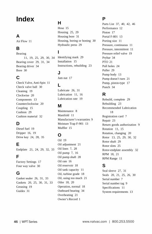
Index
AAir Flow 11
BBearing
11, 19, 25, 29, 30, 34Bearing cover 29, 31, 34Bearing driver 34Bore 30
CCheck Valve, Anti-Spin 11Check valve ball 30Cleaning 19Clockwise 20Components 13Counterclockwise 20Coupling 15Cushion 29Cushion material 32
DDiesel fuel 19Dripper 16, 19Drive key 24, 28, 35
EEndplate 21, 24, 29, 32, 33
FFactory Settings 17Four way valve 30
GGasket sealer 26, 31, 33Gaskets 20, 25, 30, 31, 33Greasing 19Guides 31
HHose 15Housing 25, 29Housing bore 31Housing, boring or honing 30Hydraulic press 29
IIdentifying mark 29Installation 15Instructions, rebuilding 23
JJam nut 17
LLubricate 26, 31Lubrication 11, 16Lubrication rate 19
MMaintenance 8Manifold 11Manufacturer’s warranties 9Moisture Trap F-901 13Muffler 15
OOil 19Oil adjustment 21Oil lines 7, 28Oil pump 7, 16Oil pump shaft 28Oil rate 16Oil reservoir 18Oil tank capacity 11Oil, turbine grade 18Oil, using too much 21Oiler 18, 20Operation, normal 18Outboard bearing 34Overheating 21Owner’s Record 1
PParts List 37, 40, 42, 46Performance 12Piston 17Portal F-801 13Porting size 11Pressure, continuous 11Pressure, intermittent 11Pressure relief valve 19Prybar 34PTO 21Pull holes 24Puller 29Pump body 13Pump doesn’t turn 21Pump, piston-type 17Punch 34
RRebuild, complete 29Rebuilding 23Recommended Lubrication
18Registration card 7Repair 23Return goods authorization 9Rotation 11, 15Rotation, changing 20Rotor 13, 25, 29, 30, 32Rotor shaft 29Rotor slots 25Rotor-endplate assembly 32RPM 18, 21RPM Range 11
SSeal sleeve 27, 31Seals 20, 21, 25, 26, 30Serial number 7Serial number tag 9Specifications 11System requirements 13

WPT Series | 47www.natvac.com | 800.253.5500
Wa
rr
an
ty
re
gis
tr
atio
n
Mod
el #
: ___
____
____
____
____
____
____
____
____
____
____
____
__Se
rial #
: ___
____
____
____
____
____
____
____
____
____
__
Busi
ness
Nam
e: _
____
____
____
____
____
____
____
____
____
____
____
____
____
____
____
____
____
____
____
____
____
____
___
Addr
ess:
___
____
____
____
____
____
____
____
____
____
____
____
____
____
____
____
Tele
phon
e: _
____
____
____
____
____
___
City
: ___
____
____
____
____
____
____
____
____
____
____
____
____
____
____
_St
ate:
____
____
_Zip
: ___
____
____
____
____
____
Dat
e Pu
rcha
sed:
____
____
____
____
____
____
____
____
____
Tank
Siz
e: __
____
____
____
____
____
____
____
____
____
____
____
_
Purc
hase
d Fr
om:
____
____
____
____
____
____
____
____
____
____
____
____
____
____
____
____
____
____
____
____
____
____
___
____
____
____
____
____
____
____
____
____
____
____
____
____
____
____
____
____
____
____
____
____
____
____
____
____
____
__
Is th
is y
our fi
rst N
atio
nal V
acuu
m E
quip
men
t pum
p pu
rcha
se?_
o Y
ES
o N
O
Prev
ious
pum
p us
ed?_
____
____
____
____
____
____
____
____
____
____
____
____
____
____
____
____
____
____
____
____
____
___
Inte
nded
use
:o
Agr
icul
tura
lo
Sep
tic
o
Com
mer
cial
o
Indu
stria
l o
Oth
er _
____
____
____
____
____
____
____
____
Com
men
ts: _
____
____
____
____
____
____
____
____
____
____
____
____
____
____
____
____
____
____
____
____
____
____
____
___
____
____
____
____
____
____
____
____
____
____
____
____
____
____
____
____
____
____
____
____
____
____
____
____
____
____
__
48 | WPT Series www.natvac.com | 800.253.5500
BuSINESS REPlY M
AIlFIRST ClASS PERM
IT NO. 146
TRAVERSE CITY, MI
NO POSTAg
E N
ECESSARY IF M
AIlED IN
ThE
uNITED
STATES
POSTAgE W
Ill BE PAID BY AD
DRESSEE
Natio
Nal Vacuum
Equipm
ENt, iN
c.P.O. BOx 685TRAVERSE CITY, M
I 49685-0685

WPT Series | 49www.natvac.com | 800.253.5500
TTank 22Threaded rod 31Torque 27, 34Troubleshooting 21Turbine oil 18
VVacuum, continuous 11Vacuum, intermittent 11Vacuum, none in tank 22Valve, changeover 19Valve, check 22Valve, four way 11Valve, pressure relief 19Valve, suction 18Vane 13, 19, 21Vane breakage 8Vane life 19Vane replacement 23, 29Vane wear 18Vanes 25, 30, 33Vanes, chipped or delaminated
25, 30
WWarranty 7Warranty procedure 9Washers 15Weight 11Woods Sure Flex Couplers 15
50 | WPT Series www.natvac.com | 800.253.5500
________________________________________________________________________________________________________________________________________________________________________________________________________________________________________________________________________________________________________________________________________________________________________________________________________________________________________________________________________________________________________________________________________________________________________________________________________________________________________________________________________________________________________________________________________________________________
Notes

WPT Series | 51www.natvac.com | 800.253.5500
________________________________________________________________________________________________________________________________________________________________________________________________________________________________________________________________________________________________________________________________________________________________________________________________________________________________________________________________________________________________________________________________________________________________________________________________________________________________________________________________________________________________________________________________________________________________
Notes

52 | WPT Series www.natvac.com | 800.253.5500
2670 Aero Park DriveTraverse City, MI 49686 uSA
231.941.0215 phone231.941.2354 Fax
[email protected] | www.natvac.com | 800.253.5500
national Vacuum equipment, inc.


