73
2500 Series Travel Trailers OWNERS MANUAL BIGFOOT INDUSTRIES (2010) INC. 4114 CROZIER ROAD, ARMSTRONG, BC, CANADA, V0E 1B6 www.bigfootrv.com
2500 Series Travel Trailers
OWNERS MANUAL
BIGFOOT INDUSTRIES (2010) INC. 4114 CROZIER ROAD, ARMSTRONG, BC, CANADA, V0E 1B6
www.bigfootrv.com
2500 Series Travel Trailers
OWNERS MANUAL
BIGFOOT INDUSTRIES (2010) INC. 4114 CROZIER ROAD, ARMSTRONG, BC, CANADA, V0E 1B6
www.bigfootrv.com
TABLE OF CONTENTS
INTRODUCTION ............................................................................................................ 1 OWNER’S MANUAL ...................................................................................................... 2 ALTERING OR MODIFYING YOUR TRAVEL TRAILER ....................................................... 2 OWNER’S RESPONSIBILITY ........................................................................................... 3 OUTLET’S RESPONSIBILITY............................................................................................ 3 NEW RECREATIONAL VEHICLE WARRANTY .................................................................. 4 WHAT IS NOT COVERED BY THE WARRANTY ................................................................ 5 GENERAL SAFETY .......................................................................................................... 6 LP GAS HEATING SYSTEM AND LP GAS APPLIANCE SAFETY REGULATIONS ................... 7
FIRE SAFETY .............................................................................................................. 9 SMOKE DETECTOR .................................................................................................... 9 EMERGENCY EXIT WINDOWS .................................................................................. 10 CARBON MONOXIDE DETECTOR ............................................................................. 10 FUEL & FUEL SYSTEM SAFETY ................................................................................. 11
PREPARATION FOR TOWING ...................................................................................... 12 TRAVEL TRAILER LOADING ...................................................................................... 12
DETERMINING & DISTRIBUTING THE TRAILER LOAD .......................................... 13 WEIGHING A TRAILER .......................................................................................... 13 BALANCE ............................................................................................................. 14 HITCH ADJUSTMENT ............................................................................................ 14 SAFETY CHAINS .................................................................................................... 15 BRAKES ................................................................................................................ 15 ELECTRONICALLY CONTROLLED BRAKES .............................................................. 16 BRAKE SYSTEM COMPONENTS ............................................................................ 16 BRAKE CONTROLLER ............................................................................................ 16 CONNECTOR PLUG .............................................................................................. 16 BREAKAWAY SWITCH .......................................................................................... 16 EMERGENCY BRAKES ........................................................................................... 16 GROUNDING ........................................................................................................ 18 TONGUE .............................................................................................................. 18 TRAILER A-FRAME ............................................................................................... 18 SWAY CONTROL .................................................................................................. 19 SPRING BARS ....................................................................................................... 19 TRAILER LOAD RATINGS ....................................................................................... 19 PERFORMING A PRE-TRIP SAFETY INSPECTION .................................................... 19 HITCHING UP YOUR TRAILER ............................................................................... 20
TIRES .......................................................................................................................... 21 INFLATION .............................................................................................................. 21
HOW OVERLOADING AFFECTS YOUR RV AND TIRES ............................................... 21 TIRE REPLACEMENT ................................................................................................ 22 IF YOU HAPPEN TO GET A FLAT TIRE ....................................................................... 22 CHANGING A FLAT TIRE .......................................................................................... 22 TIRE SAFETY INFORMATION FOR TRAVEL TRAILERS ................................................ 22 BASIC TIRE MAINTENANCE ..................................................................................... 22 FINDING YOUR VEHICLE'S RECOMMENDED TIRE PRESSURE AND LOAD LIMITS ...... 23 UNDERSTANDING TIRE PRESSURE AND LOAD LIMITS ............................................. 23 CHECKING TIRE PRESSURE ...................................................................................... 23 STEPS FOR MAINTAINING PROPER TIRE PRESSURE ................................................. 24 TIRE SIZE ................................................................................................................. 24 TIRE TREAD ............................................................................................................. 24 TIRE BALANCE AND WHEEL ALIGNMENT ................................................................ 24 TIRE REPAIR ............................................................................................................ 25 TIRE FUNDAMENTALS ............................................................................................. 25 INFORMATION ON PASSENGER VEHICLE TIRES ....................................................... 25 TIRE SAFETY TIPS ..................................................................................................... 27
PREVENTING TIRE DAMAGE ................................................................................ 27 TIRE SAFETY CHECKLIST ....................................................................................... 27 STEPS FOR DETERMINING CORRECT LOAD LIMIT ................................................ 27
GLOSSARY OF TIRE TERMINOLOGY ......................................................................... 28 ELECTRICAL SYSTEM ................................................................................................... 32
BIGFOOT 12V HOUSE ELECTRICAL SYSTEM ............................................................. 32 110V/120V ELECTRICAL SYSTEM ............................................................................. 32 45 AMP SERVICE ..................................................................................................... 34 POWER CONVERTER ............................................................................................... 34 FUSES & CIRCUIT BREAKERS .................................................................................... 35 GROUND FAULT INTERRUPTER (GFI) ....................................................................... 35 BATTERY DISCONNECT ............................................................................................ 35 BATTERY INSPECTION & CARE ................................................................................ 36 BATTERY CHARGING ............................................................................................... 36
TRAVEL TRAILER FEATURES ........................................................................................ 37 BLACK TANK RINSE SYSTEM .................................................................................... 37 DINETTE CONVERSION (WITH BUILT IN TABLE) ....................................................... 37 ENTRY & SCREEN DOORS ........................................................................................ 37 INTERIOR LIGHTING ................................................................................................ 38 MONITOR PANEL .................................................................................................... 38 OVERHEAD VENTS .................................................................................................. 38 SOFA CONVERSION (MANUAL SOFA) ...................................................................... 39 SOFA CONVERSION (ELECTRIC) ............................................................................... 39
EXTERIOR STORAGE COMPARTMENTS ................................................................... 39 INTERIOR STORAGE ................................................................................................ 39 WINDOWS .............................................................................................................. 40 VENETIAN BLINDS ................................................................................................... 40 DAY/NIGHT SHADES ................................................................................................ 40 WIRING DIAGRAMS ................................................................................................ 40 AM/FM STEREO CD OR CD/DVD PLAYER ................................................................. 41 AWNINGS ............................................................................................................... 41 EXTERIOR SHOWER ................................................................................................. 41 GENERATOR ............................................................................................................ 41 STABILIZER JACKS .................................................................................................... 41 SOLAR PANEL .......................................................................................................... 42 TELEVISION ............................................................................................................. 42 TV ANTENNA ........................................................................................................... 42
LP GAS ........................................................................................................................ 42 FILLING LP TANKS .................................................................................................... 43 SAFETY CHECK LIST ................................................................................................. 43 MANUAL REGULATOR ............................................................................................. 44 AUTOMATIC CHANGE-OVER REGULATOR ............................................................... 44 USING LP GAS SYSTEM AT LOW TEMPERATURES .................................................... 45 LP GAS (LPG) LEAK DETECTOR ................................................................................. 45
PLUMBING ................................................................................................................. 46 FRESH WATER SYSTEM ........................................................................................... 46 EXTERNAL WATER HOOK-UP (CITY OR PARK CONNECTION) ................................... 46 SELF-CONTAINED WATER SYSTEM .......................................................................... 46 FRESH WATER FILL INSTRUCTIONS (SEE DIAGRAM) ................................................ 47 SANITIZING THE FRESH WATER SYSTEM ................................................................. 48 ELECTRIC 12-VOLT DC WATER PUMP ...................................................................... 48 WINTERIZING AND DRAINING THE WATER SYSTEM ................................................ 49 SUMMER POSITION ................................................................................................ 50 WATER HEATER BYPASS SYSTEM ............................................................................ 51 HOLDING TANKS ..................................................................................................... 51 DUMPING THE HOLDING TANKS ............................................................................. 52 HOLDING TANK CARE & MAINTENANCE ................................................................. 53 TOILET..................................................................................................................... 53
APPLIANCES ............................................................................................................... 53 FANTASTIC FAN....................................................................................................... 53 FURNACE ................................................................................................................ 54 MICROWAVE OVEN ................................................................................................ 54 POWER RANGE EXHAUST HOOD ............................................................................. 54
RANGE (STOVE TOP/OVEN)..................................................................................... 54 REFRIGERATOR ....................................................................................................... 55 ROOF MOUNTED AIR CONDITIONER ....................................................................... 56 WATER HEATER ...................................................................................................... 57
EFFECTS OF LONG TERM OCCUPANCY ....................................................................... 57 VENTILATION & MOISTURE CONTROL .................................................................... 58
VENTILATE WITH OUTSIDE AIR ............................................................................ 58 MINIMIZE MOISTURE RELEASED INSIDE THE TRAVEL TRAILER ............................ 58 VENTILATE CLOSETS & CABINETS ........................................................................ 58 INSTALL A DEHUMIDIFIER .................................................................................... 58 THERMAL PANE WINDOWS ................................................................................. 58 DRIPPING CEILING VENTS .................................................................................... 59
CARE AND MAINTENANCE ......................................................................................... 59 INTERIOR MAINTENANCE ....................................................................................... 59
FABRIC BLINDS .................................................................................................... 59 CURTAINS AND UPHOLSTERY .............................................................................. 59 WALLS AND CEILING ............................................................................................ 59 CABINETRY .......................................................................................................... 59 LINOLEUM ........................................................................................................... 59 CARPET ................................................................................................................ 59 WINDOWS ........................................................................................................... 60 LAMINATE COUNTER TOPS .................................................................................. 60 DRAINS ................................................................................................................ 60 TUB AND SHOWER CARE ..................................................................................... 60
EXTERIOR MAINTENANCE ....................................................................................... 60 SIGNS OF WEATHERING: ..................................................................................... 60 WINDOWS, DOORS, VENTS & LOCKS ................................................................... 61 SEALANT RENEWAL ............................................................................................. 61 DOORS & WINDOWS ........................................................................................... 61 WINTER PROTECTION .......................................................................................... 62 WINTER PROTECTION WHILE TRAVEL TRAILER IS IN USE ..................................... 62
FORMS/CHECKLISTS ................................................................................................... 62 PRE-TRIP SAFETY INSPECTION ................................................................................. 63
TRAILER TOWING PRE-TRIP SAFETY INSPECTION CHECKLIST – PAGE 1 ................ 63 TRAILER TOWING PRE-TRIP SAFETY INSPECTION CHECKLIST – PAGE 2 ................ 64 TRAILER TOWING PRE-TRIP SAFETY INSPECTION CHECKLIST – PAGE 3 ................ 65 PRE-TRAVEL CHECK LIST ...................................................................................... 66 PRODUCT IDENTIFICATION INFORMATION .......................................................... 67 APPLIANCE & EQUIPMENT IDENTIFICATION INFORMATION ............................... 67
Page 1
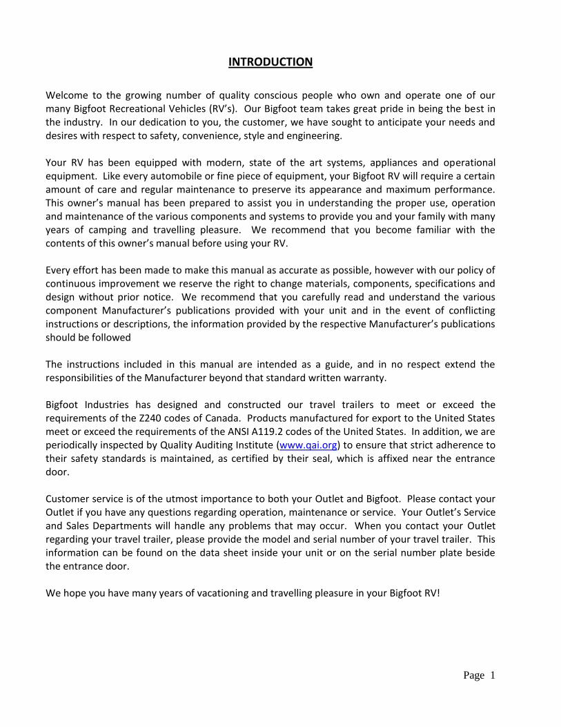
INTRODUCTION
Welcome to the growing number of quality conscious people who own and operate one of our many Bigfoot Recreational Vehicles (RV’s). Our Bigfoot team takes great pride in being the best in the industry. In our dedication to you, the customer, we have sought to anticipate your needs and desires with respect to safety, convenience, style and engineering. Your RV has been equipped with modern, state of the art systems, appliances and operational equipment. Like every automobile or fine piece of equipment, your Bigfoot RV will require a certain amount of care and regular maintenance to preserve its appearance and maximum performance. This owner’s manual has been prepared to assist you in understanding the proper use, operation and maintenance of the various components and systems to provide you and your family with many years of camping and travelling pleasure. We recommend that you become familiar with the contents of this owner’s manual before using your RV. Every effort has been made to make this manual as accurate as possible, however with our policy of continuous improvement we reserve the right to change materials, components, specifications and design without prior notice. We recommend that you carefully read and understand the various component Manufacturer’s publications provided with your unit and in the event of conflicting instructions or descriptions, the information provided by the respective Manufacturer’s publications should be followed The instructions included in this manual are intended as a guide, and in no respect extend the responsibilities of the Manufacturer beyond that standard written warranty. Bigfoot Industries has designed and constructed our travel trailers to meet or exceed the requirements of the Z240 codes of Canada. Products manufactured for export to the United States meet or exceed the requirements of the ANSI A119.2 codes of the United States. In addition, we are periodically inspected by Quality Auditing Institute (www.qai.org) to ensure that strict adherence to their safety standards is maintained, as certified by their seal, which is affixed near the entrance door. Customer service is of the utmost importance to both your Outlet and Bigfoot. Please contact your Outlet if you have any questions regarding operation, maintenance or service. Your Outlet’s Service and Sales Departments will handle any problems that may occur. When you contact your Outlet regarding your travel trailer, please provide the model and serial number of your travel trailer. This information can be found on the data sheet inside your unit or on the serial number plate beside the entrance door. We hope you have many years of vacationing and travelling pleasure in your Bigfoot RV!
Page 2
OWNER’S MANUAL
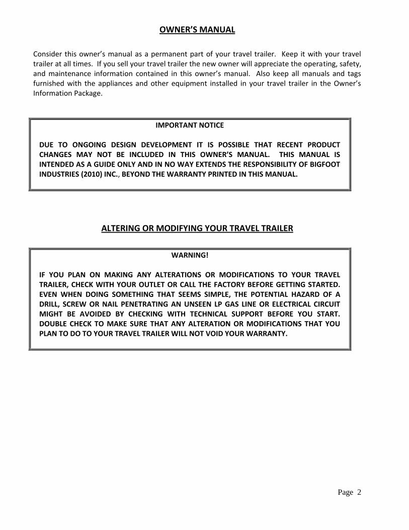
Consider this owner’s manual as a permanent part of your travel trailer. Keep it with your travel trailer at all times. If you sell your travel trailer the new owner will appreciate the operating, safety, and maintenance information contained in this owner’s manual. Also keep all manuals and tags furnished with the appliances and other equipment installed in your travel trailer in the Owner’s Information Package.
IMPORTANT NOTICE
DUE TO ONGOING DESIGN DEVELOPMENT IT IS POSSIBLE THAT RECENT PRODUCT CHANGES MAY NOT BE INCLUDED IN THIS OWNER’S MANUAL. THIS MANUAL IS INTENDED AS A GUIDE ONLY AND IN NO WAY EXTENDS THE RESPONSIBILITY OF BIGFOOT INDUSTRIES (2010) INC., BEYOND THE WARRANTY PRINTED IN THIS MANUAL.
ALTERING OR MODIFYING YOUR TRAVEL TRAILER
WARNING!
IF YOU PLAN ON MAKING ANY ALTERATIONS OR MODIFICATIONS TO YOUR TRAVEL TRAILER, CHECK WITH YOUR OUTLET OR CALL THE FACTORY BEFORE GETTING STARTED. EVEN WHEN DOING SOMETHING THAT SEEMS SIMPLE, THE POTENTIAL HAZARD OF A DRILL, SCREW OR NAIL PENETRATING AN UNSEEN LP GAS LINE OR ELECTRICAL CIRCUIT MIGHT BE AVOIDED BY CHECKING WITH TECHNICAL SUPPORT BEFORE YOU START. DOUBLE CHECK TO MAKE SURE THAT ANY ALTERATION OR MODIFICATIONS THAT YOU PLAN TO DO TO YOUR TRAVEL TRAILER WILL NOT VOID YOUR WARRANTY.
Page 3
OWNER’S RESPONSIBILITY
As the owner of a new recreational vehicle it is important to regularly and properly maintain your vehicle. BE SURE to read this owner’s manual and all appliance manuals so proper maintenance can be applied. It is your responsibility to return your RV to an authorized Outlet for any repairs and service that may be required.
OUTLET’S RESPONSIBILITY
Throughout the manufacturing process our qualified inspectors inspect your RV. However, our final inspection at the factory is not the last one. Your Outlet is to perform a final inspection of your vehicle and to help you, complete all the necessary paperwork, ensuring also that you understand the limited warranty pertaining to your new vehicle as found in the Owner’s Information Package. Please keep this package handy as a reference. Outlet’s responsibilities to their customers also include: Familiarizing you with the operation of all the systems and components of your new RV.
Explaining and reviewing the limited warranty provisions.
Assisting with completing, mailing or emailing all necessary registrations and warranty cards for
the vehicle.
Instructing you on how to request service on your recreational vehicle.
Servicing your Bigfoot recreational vehicle.
Page 4
NEW RECREATIONAL VEHICLE WARRANTY
BIGFOOT INDUSTRIES (2010) INC.’S NEW RECREATIONAL VEHICLE WARRANTY
BIGFOOT INDUSTRIES (2010) INC. (hereinafter called the “Manufacturer”) warrants that the selling Authorized Factory Outlet or the Manufacturer, will repair, replace or adjust any parts or components, except those parts and components, which are covered by separate warranties of the individual Manufacturers of such parts and components (such as appliances, windows, axles, etc.) on the new Recreational Vehicle, if such parts or components are found to be defective in factory materials or workmanship made or supplied by the Manufacturer. This Warranty is effective for twelve (12) months from the date of purchase by the original owner and is valid only for the original owner. This Warranty does not apply to the cost of transporting materials or the Recreational Vehicle to and/or from the repair site. In the case where the nature of the repairs necessitates the repairs to be done at the factory, the transportation costs to and from the factory are the responsibility of the owner, unless agreed otherwise in writing.
Note 1: Minor adjustments, for example to interior/exterior doors, cabinet latches, plumbing fittings, etc., will be covered by this Warranty for the first ninety (90) days, after which they are normal services and the responsibility of the owner.
Note 2: The proper maintenance of the Recreational Vehicle is the responsibility of the owner. Deterioration from weather and travel movement can reduce the effectiveness and appearance of the exterior sealants, mechanical fasteners, etc. The selling Outlet’s service department should inspect the Recreational Vehicle at least every six (6) months. Failure to do so may void this Warranty in relation to such areas.
The selling Outlet must receive any claims relating to any alleged defects within ten (10) days after the discovery of any alleged defects
The Warranty applies only to new Recreational Vehicles operated in a normal manner. This Warranty does not apply to any Recreational Vehicle placed on rental, registered with a rental organization, or used for commercial purposes. Any defects that, in the opinion of the Manufacturer, have arisen as a result of misuse, acts of nature, negligence, causes beyond the control of the Manufacturer, or unauthorized alterations to the Recreational Vehicle are not covered by this Warranty.
Repairs under this Warranty (parts and labour) will be made at no charge to the owner during the period of this Warranty using the Manufacturer’s service parts and authorized re-manufactured parts.
This Warranty is valid only if the Warranty Registration Certificate is properly completed and forwarded to the Manufacturer within fifteen (15) days of the date of purchase. The selling Outlet will assist the owner with the completion of the Warranty Registration Certificate.
The foregoing Warranty is the only express warranty on the part of the Manufacturer and the selling Outlet. The owner may have other rights, which may vary by jurisdiction.
The foregoing express Warranty is in substitution for and excludes all other liabilities of any kind whether arising under statute, in tort, by implication of law or otherwise, including, to the full extent as may be allowed by law, liability for any other representations respecting the Recreational Vehicle, statutory warranties or implied warranties or conditions as to its merchantability or fitness. Any implied Warranty or condition as to merchantability or fitness for particular purpose is limited to the applicable Warranty duration period as specified herein.
In no event shall the Manufacturer or the selling Outlet be liable for the loss of, or damage to the Recreational Vehicle or its parts, loss of use of the Recreational Vehicle, loss of time, inconvenience, commercial loss, or special, consequential or other damages or any other claims relating to or arising from any defect in factory materials or workmanship, whenever found, except as provided for herein.
The Manufacturer is constantly improving its products. Changes are made from time to time as they are developed. The Manufacturer and the selling Outlet are under no obligation to retrofit these changes to earlier models. All features and specifications are subject to change without notice.
Page 5
WHAT IS NOT COVERED BY THE WARRANTY
This Warranty does not cover: The tires and batteries, which are covered by the separate warranties of the respective
manufacturers of these components. Defects caused by or related to:
Abuse, misuse, negligence or accident Failure to comply with instructions contained in the owner’s information package Alteration or modification of the travel trailer Environmental conditions (salt, hail, ultraviolet exposure, chemicals in the atmosphere, etc.)
Normal deterioration due to wear or exposure, such as fading of fabrics or drapes, exterior plastics, carpet wear, gelcoat fading, paints, etc.
Normal maintenance and service items, such as light bulbs, fuses, lubricants, sealants, etc. Transportation to and from Outlet or Bigfoot Industries Service Center location, loss of time,
inconvenience, commercial loss, loss of use, towing charges, bus fares, vehicle rental, incidental charges such as telephone calls or hotel bills, or other incidental or consequential damages.
Some jurisdictions may not allow the exclusion or limitation of incidental or consequential damages, so the above limitation or exclusion may not apply to you. This warranty gives you specific legal rights and you may also have other rights that vary from jurisdiction to jurisdiction. The Manufacturer is not responsible for any undertaking, representation or warranty made by any Outlet or other person beyond those expressly set forth in this warranty.
Page 6
GENERAL SAFETY
Bigfoot Industries (2010) Inc. continually strives to produce quality recreational vehicles that meet and exceed the requirements of Federal Motor Vehicle Safety Standards. As the owner of this Bigfoot Recreational vehicle, if you believe you have discovered a safety concern, please notify Bigfoot at: Bigfoot Industries (2010) Inc. 4114 Crozier Road Armstrong, BC Canada V0E 1B6 Tel: 1-250-546-2155 If you are a US Citizen, and feel this concern cannot be addressed satisfactorily by Bigfoot Industries (2010) Inc., as per 49 CFR Part 575.6(2)(i), Consumer Information, and Part 577.5, Defect and Non-compliance Notification, you may submit a complaint to the: Administrator National Highway Traffic Safety Administration 400 Seventh Street, S.W. Washington, DC 20590 Or call the Vehicle Safety Hotline at: 1-888-327-4236 TTY: 1-800-424-9153
Page 7
LP GAS HEATING SYSTEM AND LP GAS APPLIANCE SAFETY REGULATIONS
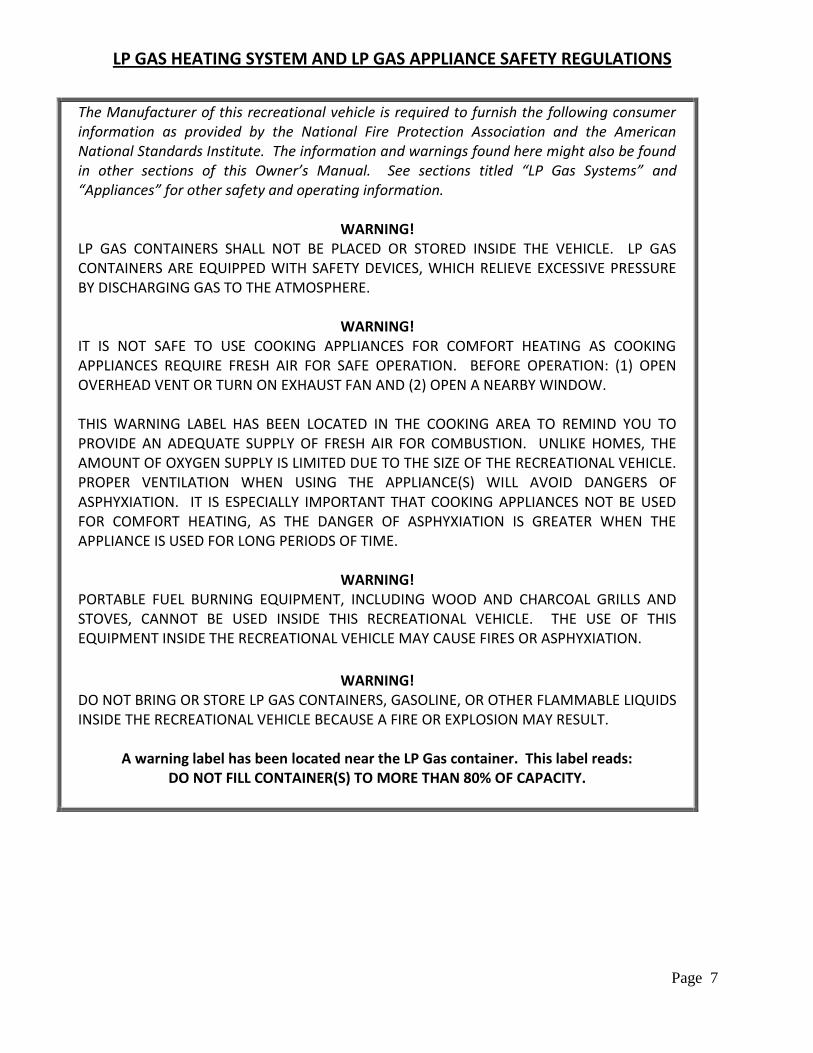
The Manufacturer of this recreational vehicle is required to furnish the following consumer information as provided by the National Fire Protection Association and the American National Standards Institute. The information and warnings found here might also be found in other sections of this Owner’s Manual. See sections titled “LP Gas Systems” and “Appliances” for other safety and operating information.
WARNING! LP GAS CONTAINERS SHALL NOT BE PLACED OR STORED INSIDE THE VEHICLE. LP GAS CONTAINERS ARE EQUIPPED WITH SAFETY DEVICES, WHICH RELIEVE EXCESSIVE PRESSURE BY DISCHARGING GAS TO THE ATMOSPHERE.
WARNING! IT IS NOT SAFE TO USE COOKING APPLIANCES FOR COMFORT HEATING AS COOKING APPLIANCES REQUIRE FRESH AIR FOR SAFE OPERATION. BEFORE OPERATION: (1) OPEN OVERHEAD VENT OR TURN ON EXHAUST FAN AND (2) OPEN A NEARBY WINDOW. THIS WARNING LABEL HAS BEEN LOCATED IN THE COOKING AREA TO REMIND YOU TO PROVIDE AN ADEQUATE SUPPLY OF FRESH AIR FOR COMBUSTION. UNLIKE HOMES, THE AMOUNT OF OXYGEN SUPPLY IS LIMITED DUE TO THE SIZE OF THE RECREATIONAL VEHICLE. PROPER VENTILATION WHEN USING THE APPLIANCE(S) WILL AVOID DANGERS OF ASPHYXIATION. IT IS ESPECIALLY IMPORTANT THAT COOKING APPLIANCES NOT BE USED FOR COMFORT HEATING, AS THE DANGER OF ASPHYXIATION IS GREATER WHEN THE APPLIANCE IS USED FOR LONG PERIODS OF TIME.
WARNING! PORTABLE FUEL BURNING EQUIPMENT, INCLUDING WOOD AND CHARCOAL GRILLS AND STOVES, CANNOT BE USED INSIDE THIS RECREATIONAL VEHICLE. THE USE OF THIS EQUIPMENT INSIDE THE RECREATIONAL VEHICLE MAY CAUSE FIRES OR ASPHYXIATION.
WARNING!
DO NOT BRING OR STORE LP GAS CONTAINERS, GASOLINE, OR OTHER FLAMMABLE LIQUIDS INSIDE THE RECREATIONAL VEHICLE BECAUSE A FIRE OR EXPLOSION MAY RESULT.
A warning label has been located near the LP Gas container. This label reads: DO NOT FILL CONTAINER(S) TO MORE THAN 80% OF CAPACITY.
Page 8
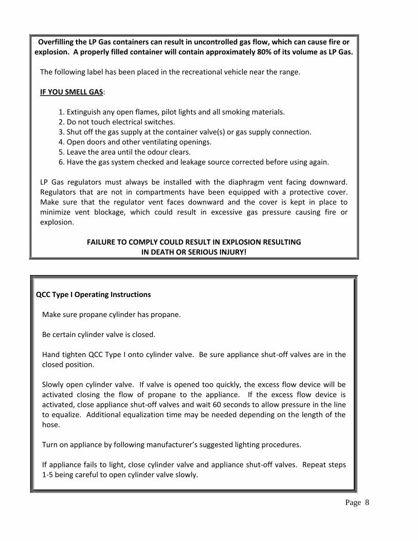
Overfilling the LP Gas containers can result in uncontrolled gas flow, which can cause fire or explosion. A properly filled container will contain approximately 80% of its volume as LP Gas.
The following label has been placed in the recreational vehicle near the range. IF YOU SMELL GAS: 1. Extinguish any open flames, pilot lights and all smoking materials. 2. Do not touch electrical switches. 3. Shut off the gas supply at the container valve(s) or gas supply connection. 4. Open doors and other ventilating openings. 5. Leave the area until the odour clears. 6. Have the gas system checked and leakage source corrected before using again. LP Gas regulators must always be installed with the diaphragm vent facing downward. Regulators that are not in compartments have been equipped with a protective cover. Make sure that the regulator vent faces downward and the cover is kept in place to minimize vent blockage, which could result in excessive gas pressure causing fire or explosion.
FAILURE TO COMPLY COULD RESULT IN EXPLOSION RESULTING IN DEATH OR SERIOUS INJURY!
QCC Type I Operating Instructions
Make sure propane cylinder has propane. Be certain cylinder valve is closed. Hand tighten QCC Type I onto cylinder valve. Be sure appliance shut-off valves are in the closed position. Slowly open cylinder valve. If valve is opened too quickly, the excess flow device will be activated closing the flow of propane to the appliance. If the excess flow device is activated, close appliance shut-off valves and wait 60 seconds to allow pressure in the line to equalize. Additional equalization time may be needed depending on the length of the hose. Turn on appliance by following manufacturer’s suggested lighting procedures. If appliance fails to light, close cylinder valve and appliance shut-off valves. Repeat steps 1-5 being careful to open cylinder valve slowly.
Page 9
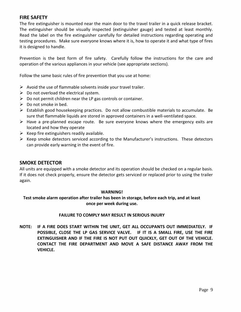
FIRE SAFETY The fire extinguisher is mounted near the main door to the travel trailer in a quick release bracket. The extinguisher should be visually inspected (extinguisher gauge) and tested at least monthly. Read the label on the fire extinguisher carefully for detailed instructions regarding operating and testing procedures. Make sure everyone knows where it is, how to operate it and what type of fires it is designed to handle. Prevention is the best form of fire safety. Carefully follow the instructions for the care and operation of the various appliances in your vehicle (see appropriate sections). Follow the same basic rules of fire prevention that you use at home: Avoid the use of flammable solvents inside your travel trailer. Do not overload the electrical system. Do not permit children near the LP gas controls or container. Do not smoke in bed. Establish good housekeeping practices. Do not allow combustible materials to accumulate. Be
sure that flammable liquids are stored in approved containers in a well-ventilated space. Have a pre-planned escape route. Be sure everyone knows where the emergency exits are
located and how they operate Keep fire extinguishers readily available. Keep smoke detectors serviced according to the Manufacturer’s instructions. These detectors
can provide early warning in the event of fire.
SMOKE DETECTOR All units are equipped with a smoke detector and its operation should be checked on a regular basis. If it does not check properly, ensure the detector gets serviced or replaced prior to using the trailer again.
WARNING! Test smoke alarm operation after trailer has been in storage, before each trip, and at least
once per week during use.
FAILURE TO COMPLY MAY RESULT IN SERIOUS INJURY NOTE: IF A FIRE DOES START WITHIN THE UNIT, GET ALL OCCUPANTS OUT IMMEDIATELY. IF
POSSIBLE, CLOSE THE LP GAS SERVICE VALVE. IF IT IS A SMALL FIRE, USE THE FIRE EXTINGUISHER AND IF THE FIRE IS NOT PUT OUT QUICKLY, GET OUT OF THE VEHICLE. CONTACT THE FIRE DEPARTMENT AND MOVE A SAFE DISTANCE AWAY FROM THE VEHICLE.
Page 10
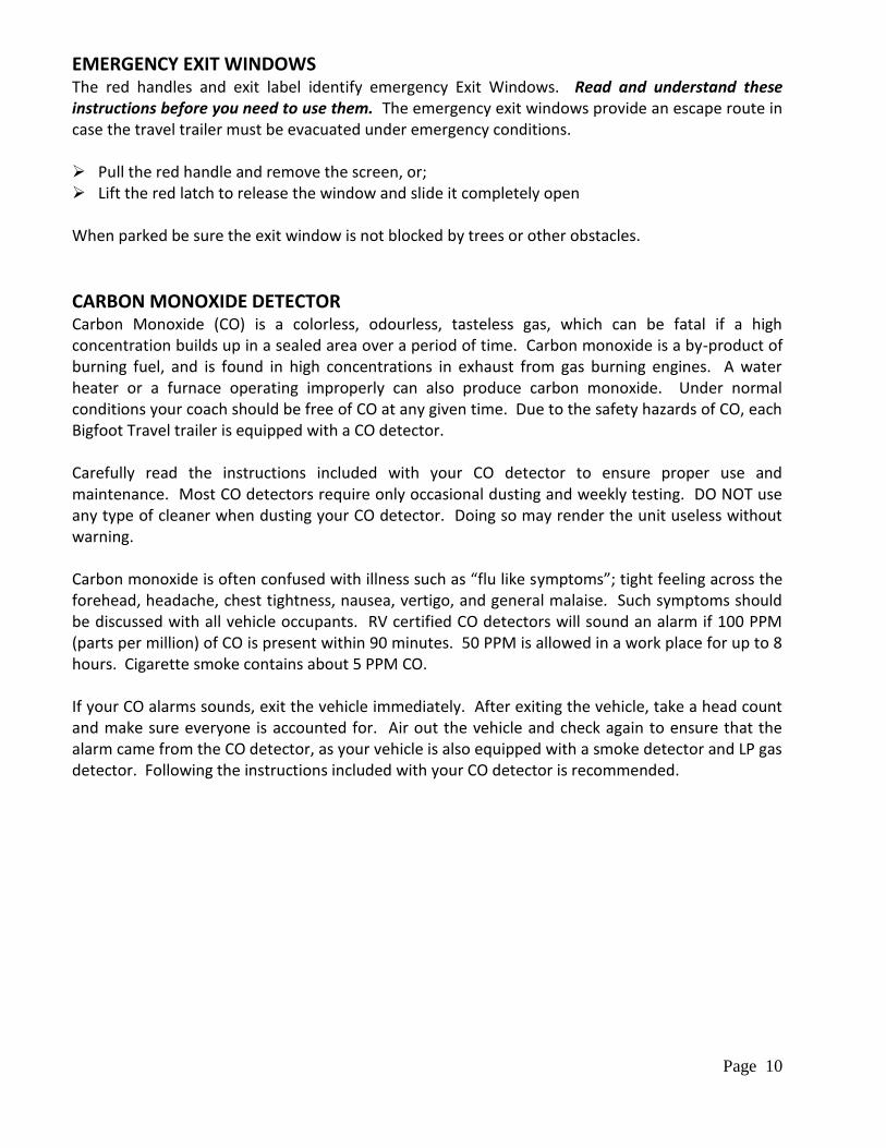
EMERGENCY EXIT WINDOWS The red handles and exit label identify emergency Exit Windows. Read and understand these instructions before you need to use them. The emergency exit windows provide an escape route in case the travel trailer must be evacuated under emergency conditions. Pull the red handle and remove the screen, or; Lift the red latch to release the window and slide it completely open When parked be sure the exit window is not blocked by trees or other obstacles.
CARBON MONOXIDE DETECTOR Carbon Monoxide (CO) is a colorless, odourless, tasteless gas, which can be fatal if a high concentration builds up in a sealed area over a period of time. Carbon monoxide is a by-product of burning fuel, and is found in high concentrations in exhaust from gas burning engines. A water heater or a furnace operating improperly can also produce carbon monoxide. Under normal conditions your coach should be free of CO at any given time. Due to the safety hazards of CO, each Bigfoot Travel trailer is equipped with a CO detector. Carefully read the instructions included with your CO detector to ensure proper use and maintenance. Most CO detectors require only occasional dusting and weekly testing. DO NOT use any type of cleaner when dusting your CO detector. Doing so may render the unit useless without warning. Carbon monoxide is often confused with illness such as “flu like symptoms”; tight feeling across the forehead, headache, chest tightness, nausea, vertigo, and general malaise. Such symptoms should be discussed with all vehicle occupants. RV certified CO detectors will sound an alarm if 100 PPM (parts per million) of CO is present within 90 minutes. 50 PPM is allowed in a work place for up to 8 hours. Cigarette smoke contains about 5 PPM CO. If your CO alarms sounds, exit the vehicle immediately. After exiting the vehicle, take a head count and make sure everyone is accounted for. Air out the vehicle and check again to ensure that the alarm came from the CO detector, as your vehicle is also equipped with a smoke detector and LP gas detector. Following the instructions included with your CO detector is recommended.
Page 11
FUEL & FUEL SYSTEM SAFETY
WARNING! LP GAS SAFETY - SHUT OFF ALL LP GAS SYSTEMS BEFORE FILLING THE GASOLINE TANK
LP appliances should never be operated while the vehicle is in motion. If the pungent odour of LP gas is detected, immediately shut off the LP gas valve and check the LP gas label for further instructions. All units are equipped with an LP Gas detector. This detector should not be relied on solely; if you detect the smell of LP gas, shut off the gas valve immediately. See other sections of this manual for more information on the LP Gas System. NOTE: IT IS VERY IMPORTANT TO READ THE OWNER’S MANUALS SUPPLIED WITH EACH
SAFETY DEVICE FOR DETAILS ON TESTING AND MAINTENANCE OF THESE IMPORTANT SAFETY DEVICES.
These manuals are found in your Owner’s Information Package.
! DANGER !
Any motorized vehicle or any motorized equipment powered with flammable liquid can cause fire, explosion, or asphyxiation if stored or transported within the recreational vehicle. To reduce the risk of fire, explosion, or asphyxiation: 1) Passengers shall not ride in the vehicle storage area while vehicles are present. 2) Occupants shall not sleep in the vehicle storage area while vehicles are present. 3) Doors and windows in walls of separation (if installed) shall be closed while vehicles are
present. 4) Fuel shall be run out of engines of stored vehicles after shutting off fuel at the tank. 5) Motor fuel shall not be stored or transported inside this vehicle. 6) The vehicle storage area shall be ventilated. 7) Propane appliances, pilot lights, or electrical shall not be operated when motorized or
motorized equipment are inside the vehicle. FAILURE TO COMPLY COULD RESULT IN AN INCREASED RISK OF FIRE, EXPLOSION, ASPHYXIATION, DEATH OR SERIOUS INJURY! WARNING! Do not sleep in this area! Failure to comply may result in death or serious injury!
Page 12
PREPARATION FOR TOWING
Your towing equipment, its adjustments and how you load the trailer will have a great effect on trailer towing stability and handling. The following will help you select, adjust and load your equipment in a manner that will help produce acceptable towing characteristics: Use a tow vehicle that is large enough for your trailer and has the needed power and heavy-duty
running gear. The tow vehicle must be rated by its manufacturer both to tow the gross weight, and to carry the hitch weight, of the fully loaded trailer.
Use a weight distributing hitch rated not less than the trailer gross vehicle weight rating (GVWR). Follow the tow vehicle and hitch manufacturer’s instructions. Install the hitch ball as close as practical to the rear bumper to minimize rear over-hang.
Use a sway control system, installed and adjusted according to the sway control manufacturer’s instructions.
Use a break controller that automatically applies the brakes in proportion to the tow vehicle brakes.
Adjust the brake controller so that the brakes of the trailer operate as quickly as possible without locking-up the tires of the loaded trailer during strong braking.
Do not use your vehicle’s cruise control while towing. Inflate the rear tires of the tow vehicle to the maximum cold pressure. Inflate the trailer tires to their maximum cold pressure. Load the trailer placing heavy objects and goods as close to the trailer axle as possible. Do not
place heavy objects on the rear bumper or on the tongue. Try to maintain 10-15% of the trailer’s weight on the hitch.
Adjust the hitch ball height so that the fully loaded trailer is level front to rear when attached to the fully loaded tow vehicle with the hitch spring bars tightened.
When loading the trailer, do not exceed the trailer gross axle weight rating (GAWR). Weigh the fully loaded trailer from time to time to verify that trailer GAWR and GVWR are not exceeded, and that the loads on the right hand and left hand wheels are approximately equal.
Do not exceed the tow vehicle gross axle weight rating (GAWR) or gross vehicle weight rating (GVWR). Weigh the tow vehicle from time to time to verify these loadings.
TRAVEL TRAILER LOADING NOTE: THE USE OF AN EQUALIZER HITCH IS RECOMMENDED. DISCUSS THE OPTIONS WITH
YOUR OUTLET AND REFER TO THE MANUFACTURER’S MANUAL FOR INSTRUCTIONS. A trailer chassis (springs, wheels, tires, axles, frame and tongue) is designed to carry a certain maximum weight. This load consists of the weight of the empty travel trailer itself, and weight added in the form of food, clothing, and anything else that may be stored in, or attached to, the trailer. The maximum load for which a trailer is designed is called the Gross Vehicle Weight Rating (GVWR) and it is the total of the weight on the axle and the trailer tongue. Another critical weight factor is the Gross Axle Weight Rating (GAWR). This is the maximum weight a specific axle is designed to carry. This rating represents the empty vehicle’s axle weight plus the
Page 13
added load. On trailers with more than one axle, the weight is divided between each axle and each has its own GAWR. The total of all axle loads plus the tongue weight must not exceed the trailer GVWR. Tongue weight is the amount of pressure exerted downward on the hitch ball. Your trailer is designed for maximum tongue weight that must NOT EXCEED your hitch tongue weight ratings.
WARNING! Do not exceed the specified tongue weight as you could do damage to the trailer frame. Also,
overloading could result in poor handling and braking
Determining & Distributing the Trailer Load The gross vehicle weight rating (GVWR) for your trailer is found on the label attached near the entry door of the travel trailer. You must compare the GVWR to the actual loaded weight of your trailer. If the loaded weight of your trailer exceeds the GVWR, your trailer is overloaded and you will have to remove items to bring the weight down to or below the GVWR.
WARNING! Do not exceed the rated load of the tow vehicle, the trailer, or the rated load of any axle.
NOTE: If other equipment or options are installed after the trailer leaves the factory, the weight
of these items must be subtracted from the total of the load and cargo carrying capacities.
WARNING! Do not install any type of weight carrying rack, frame, or hitch to the rear bumper, front A-frame assembly, chassis or body component of the trailer. Damage to the trailer body and unstable handling characteristics may result. Add-ons to the rear bumper, front A-frame
assembly or chassis will void your warranty on structural components.
WARNING! Do not store or carry LP gas containers, gasoline, or other flammable liquids inside your
trailer.
Weighing a Trailer You can find a public scale by looking under "Weighers—Public" in the yellow pages of your local telephone directory. Trailers must be carefully weighed to make sure that loads are properly distributed, front to rear as well as left to right. There are two additional considerations with trailer weights: The tow vehicle pulling the trailer and The hitching system that connects the two. Both the tow vehicle and the hitching system have weight capacities which affect the safe handling of the vehicle. As a new RV owner or driver you should be aware of this.
Page 14
Tow Vehicle—do not exceed the GVWR of the tow vehicle. This includes the curb weight of the
vehicle, payload, and hitch weight. Hitch weight is the percentage of the trailer weight that is placed on the trailer coupler of the tow vehicle. (Refer to the next section on Trailer Vehicle Hitch Weight.) Tow vehicles also have GAWR limits. Payload and hitch weight must be divided evenly between the axles to conform to the maximum weight limits and to avoid over-steering problems.
Trailer Vehicle Hitch Weight—approximately 8-15 percent of a trailer's gross weight is designed to be loaded in front of the front axle and onto the hitching mechanism. This ensures needed stability for road handling. If your trailer is not stable, you may have a problem with not enough weight on the hitch. Here are some methods to figure out hitch weight:
Park your loaded trailer on a scale so that the hitch coupler extends beyond the end of the
scale, but the tongue jack post (the post on the front of the trailer which rests on the ground when unhitched) is on the scale.
Block the trailer vehicle wheels, unhitch the tow vehicle, and obtain a weight rating. This is the curb weight of the trailer vehicle alone.
Place a jack stand (or 4" x 4" blocks) under the coupler (beyond the scale) so that the tongue jack post is supported off the scale and the trailer is fairly level. Note this weight rating.
Subtract the reading in #2 from the reading in #3 for the hitch weight. In any RV, vehicle stability and safety can be affected by weight distribution. If, for example, rear axle weight is low, it is best to load the heaviest supplies toward the rear. Keep heaviest supplies low, to keep the center of gravity low and ensure best handling.
Balance Before you tow a trailer, evaluate the trailer weight distribution. Hitch weights for travel trailers should typically be at least 8 percent of the trailer's gross weight for acceptable handling. In some cases it can go to 15 percent or higher. Hitch weight for larger trailers is limited by the capacities of tow vehicles and hitches. The strongest load-distributing hitch is rated for a maximum hitch weight of 1200 pounds. Most passenger car suspensions cannot handle that much weight and the trailer should be towed with a pickup truck or van. Improper weight distribution can cause the trailer to fishtail (sway back and forth across the lane).
Hitch Adjustment If your hitch weight is less than 10 percent of the gross trailer weight, you can compensate for some of this by loading heavy supplies such as tools and canned goods as far forward as possible. If your trailer's water tank is behind the axle(s), travel with as little water in the tank as possible to reduce weight in the rear. Trailers with water tanks located in front usually handle best when the tanks are full, because the water adds to hitch weight. Be sure that the spring bars of the load-distributing hitch are rated high enough to handle the hitch weight of your trailer, plus a safety margin of at least 10 percent. Check for adequate rear
Page 15
suspension of the tow vehicle. This means that the vehicle sits relatively level prior to hitching the trailer. Load-distributing hitches are designed to distribute the hitch weight relatively evenly to all axles of the tow vehicle and trailer. The tow vehicle and trailer should be in a level position (attitude) in order for the hitch to do its job properly. Here is how to check: 1) With the tow vehicle loaded for a trip, measure the distance between the vehicle and the
ground at reference points, which you can establish, in front and rear. Keep the figures handy for later use.
2) Hitch the trailer and adjust the tension on the spring bars so the tow vehicle remains at roughly the same attitude (i.e., if the rear drops an inch after hitching, the front should also drop an inch).
3) Inspect the trailer to be sure it is level. If not, hitch ball height should be raised or lowered, as
necessary. You may need spring bars rated for more weight if you cannot keep the tow vehicle from sagging in the rear.
Safety Chains Safety chains are required for travel trailers. The purpose of safety chains is to prevent the trailer from separating from the tow vehicle in event of hitch failure such as a hitch ball that has loosened. The chains should be crossed in an "X" fashion below the ball mount, with enough slack that they do not restrict turning or allow the coupler to hit the ground.
Brakes As with any vehicle, the proper operation of the tow vehicle’s braking system is essential for vehicle control. Brakes are required on any trailer coach or camp trailer having a gross weight of 1500 lbs. or more. Typical braking distances increase dramatically with the addition of a trailer and its contents in tow. Periodic inspection and maintenance of the vehicles braking system shall follow the automobile manufacturer’s recommendations at a minimum. Reference the manufacturer’s recommendations for brake selection. Trailers are equipped with separate brakes that should be considered a continuation of the tow vehicle’s brake system. The trailer brakes are integrated into the tow vehicle brakes and activate in combination with the tow vehicle brakes. Most conventional and fifth-wheel trailers have electric brakes, activated by a controller in the tow vehicle. The controller automatically coordinates the tow vehicle and trailer braking so the two systems work together when the brake pedal is applied. The controller can also be helpful in stabilizing a trailer that sways because of bad road conditions. Manually applying the trailer brakes by using the hand lever on the controller will re-stabilize a trailer that is likely to sway.
Page 16
Electronically Controlled Brakes The electric brakes on your trailer are similar to the drum brakes on your car or truck. The basic difference between them is that your trailer brakes are operated by 12-volt direct current from the tow vehicle, rather than by direct hydraulic action. The brakes have been factory calibrated for smooth positive response. During the break-in period, you may experience squeaking brakes. This is normal and will cease after a few miles of break-in wear. These brakes provide both automatic and manual control for trailer brakes, and require that the tow vehicle be equipped with additional electrical wiring and a control box in the tow vehicle that can activate the brake system either automatically or by the driver of the tow vehicle. When the tow vehicle brakes are applied, an electric current energizes a magnet for each brake, which moves an actuating lever to activate the trailer brakes in proportion the rate of deceleration. When the tow vehicle brake pedal is released, the magnet is de-energized, and the trailer brakes are released.
Brake System Components The braking system on your trailer consists of several major components, all of which must function properly for safe and responsive braking.
Brake Controller Note – the brake controller is not supplied with your trailer. The electric trailer brakes are automatically applied by the brake controller, which is usually mounted within easy reach of the tow vehicle driver.
WARNING! Do not install a fuse in the circuit between the tow vehicle battery and an electric or
electronic brake controller. A blown fuse will cause the controller to cease functioning both automatically and manually, causing loss of trailer braking with no advance warning.
Connector Plug The multi-pin cord connector at the front of the trailer transfers power from the tow vehicle battery to the trailer brakes, exterior lighting system and battery.
Breakaway Switch The breakaway switch is located on the trailer tongue. It has a steel cable (lanyard) fastened to it which will reach to the frame of the tow vehicle. This device is one of the most vital components on your trailer’s braking system.
Emergency Brakes Breakaway switches are also required for any trailer having a gross weight of 1500 lbs. or more and manufactured after December 31, 1955. They are designed to activate trailer brakes if the tow
Page 17
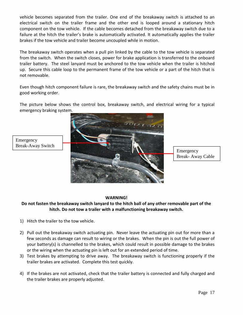
vehicle becomes separated from the trailer. One end of the breakaway switch is attached to an electrical switch on the trailer frame and the other end is looped around a stationary hitch component on the tow vehicle. If the cable becomes detached from the breakaway switch due to a failure at the hitch the trailer’s brake is automatically activated. It automatically applies the trailer brakes if the tow vehicle and trailer become uncoupled while in motion. The breakaway switch operates when a pull pin linked by the cable to the tow vehicle is separated from the switch. When the switch closes, power for brake application is transferred to the onboard trailer battery. The steel lanyard must be anchored to the tow vehicle when the trailer is hitched up. Secure this cable loop to the permanent frame of the tow vehicle or a part of the hitch that is not removable. Even though hitch component failure is rare, the breakaway switch and the safety chains must be in good working order. The picture below shows the control box, breakaway switch, and electrical wiring for a typical emergency braking system.
WARNING!
Do not fasten the breakaway switch lanyard to the hitch ball of any other removable part of the hitch. Do not tow a trailer with a malfunctioning breakaway switch.
1) Hitch the trailer to the tow vehicle. 2) Pull out the breakaway switch actuating pin. Never leave the actuating pin out for more than a
few seconds as damage can result to wiring or the brakes. When the pin is out the full power of your battery(s) is channelled to the brakes, which could result in possible damage to the brakes or the wiring when the actuating pin is left out for an extended period of time.
3) Test brakes by attempting to drive away. The breakaway switch is functioning properly if the trailer brakes are activated. Complete this test quickly.
4) If the brakes are not activated, check that the trailer battery is connected and fully charged and
the trailer brakes are properly adjusted.
Emergency
Break-Away Switch Emergency
Break- Away Cable
Page 18
5) Obtain service repair if the trailer brakes do not operate after making these checks. 6) Reinsert the breakaway switch actuating pin before towing the trailer. Remove the pull pin every 3 months and lubricate it with light oil. Before reinserting the pin, spray the inside of the switch with an electrical contact cleaner to prevent corrosion. Test the breakaway switch operation before each trip as follows:
WARNING! Do not leave the pull pin out of the breakaway switch for more than a few seconds (30 to 60
seconds) or the battery will be drained. Do not use the breakaway switch for a parking brake.
Grounding A poor ground circuit from the brakes to the tow vehicle battery can be as detrimental to efficient braking as poor primary circuit from the battery to the brakes.
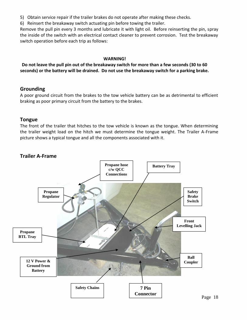
Tongue The front of the trailer that hitches to the tow vehicle is known as the tongue. When determining the trailer weight load on the hitch we must determine the tongue weight. The Trailer A-Frame picture shows a typical tongue and all the components associated with it.
Trailer A-Frame
Propane
Regulator
Propane hose
c/w QCC
Connections
Propane
BTL Tray
Safety Chains 7 Pin
Connector
Ball
Coupler
Battery Tray
Safety
Brake
Switch
12 V Power &
Ground from
Battery
Front
Levelling Jack
Page 19
Sway Control You should have good trailer handling if the weight and hitch adjustments are correct. However, the coupling between a tow vehicle and trailer should also prevent side to side motion for best possible towing comfort and safety. If you detect sway in your trailer, stop and check to see if the load has shifted. Check for suspension problems and make sure the tires and wheels are secure and inflated properly. Be sure the trailer hitch is secure. A small reduction in tire air pressure or a slight increase in tongue weight may help. A sway control device should be included when the hitch is installed. This device helps give the tow vehicle and trailer a "one-vehicle" feel. There are two basic types of sway control systems available: Friction bar—slides in and out and is activated by the motion of the vehicles. When you brake or
turn, the trailer weight compresses the bar, which then compresses the trailer against the tow vehicle.
Dual cam sway control—usually works better for large trailers with heavy tongue weights. The cam action is applied to the spring of the trailer to reduce sway and shifts the weight forward. It also adjusts weight shifts, which allows the trailer to follow the tow vehicle.
Spring Bars For trailers with multiple axles, Spring Bars (also called load-levelling bars) are often used to distribute the tongue weight among all axles of the tow vehicle and trailer with a weight-distribution hitch.
Trailer Load Ratings Trailer manufacturers provide load ratings on certification tags at various points inside or outside the trailer. The certification tags are usually placed on the front left-side exterior wall of a travel trailer. Know where to locate this information on your trailer and review this information regularly so you are familiar with the load ratings. At no times should these load ratings be exceeded.
Performing a Pre-Trip Safety Inspection Before the start of a trip involving trailer towing, a visual pre-trip safety inspection shall always be conducted, regardless of the length of the trip. The safety inspection should thoroughly evaluate the tow vehicle, trailer, and hitch to ensure everything is in proper operating order. Additionally, the load weight and distribution on the trailer should be inspected. If issues are found during the pre-trip inspection, corrective action must be completed before the trip can be taken. For this reason, it is recommended to conduct the pre-trip safety inspection well in advance of the planned departure, so that no surprise inspection issues delay or prevent a trip from taking place. An example of a pre-trip inspection checklist is included in the forms section at the back of this manual.
Page 20
Hitching Up Your Trailer Hitching up your trailer will become routine with experience. Make it a habit to examine all hitch components before hitching up the trailer. If you have a conventional ball hitch, check for cracked or bent parts, cracked welds, deformed or stripped bolts. Inspect the weight distributing hitch spring base and chains. Be sure the hitch ball is tight and well lubricated. Check the trailer tongue for cracks. Be sure the ball locking device works freely. Inspect the safety chains. If you find defects in any hitch component, correct it before towing the trailer. Before attempting to hitch up your trailer, read the instructions provided by the hitch manufacturer. Your trailer coupler is built for a 2-5/16” hitch ball. Your hitch ball must be this size. The following instructions are usable in most cases. If the instructions provided with your hitch deviate from these instructions, follow the manufacturer’s instructions. 1) Turn the tongue jack crank clockwise to raise the tongue and coupler. Raise the tongue
sufficiently to clear the hitch ball on the tow vehicle. 2) Back the tow vehicle until the hitch ball is under the hitch ball socket. If you are working alone, a
backing aide mirror may be helpful. 3) Be sure the coupler latch locking lever is fully open. Lower the tongue jack until the ball is firmly
seated in the socket. Close the coupler latch and secure it with a locking pin or bolt. 4) Raise the tow vehicle and trailer with the tongue jack high enough to allow room to install the
weight distributing hitch spring bars. 5) Attach the spring bars according to the weight distributing hitch manufacturer’s instructions. 6) After adjusting the spring bars, lower the tongue jack, remove the dolly wheel or foot, and fully
retract the jack. Note: the trailer must be relatively level, front to back. Any tilt must be very slight. Do not overload the torsion bars, as the trailer may become extremely unstable at road speeds.
7) Install the sway control system according to the manufacturer’s instructions. 8) Connect the safety chains of the trailer to the tow vehicle. Loop each chain through a suitable
attachment eye on the tow vehicle. To adjust the chain length, insert the chain quick coupler through an appropriate chain link.
9) Connect the breakaway switch lanyard to an attachment eye on the tow vehicle. Be sure the breakaway switch lanyard is adjusted so the switch is not activated during a full “jackknife” turn.
10) Plug the trailer electrical cord into the matching tow vehicle socket. 11) Run an operational check of stop lights and turn on indicators, running lights and electrical
brakes before driving.
WARNING! Never attach safety chains to the hitch ball or any removable part of the hitch.
Do not connect the breakaway switch lanyard to the hitch ball or any removable part of the hitch. Note: a battery must be installed in the system in order for the system to operate.
Page 21
TIRES
Your travel trailer is equipped with wheels and tires selected to match the capacity specifications of the trailer, as designed by the Manufacturer. Under normal circumstances and with proper tire maintenance, you should receive many miles of trouble free service. Tires on your vehicle must be of the proper size and correctly inflated for the load. All tires (including the spare tire) on the vehicle should be of the same size, type, and construction. All tires must be free of punctures, cuts, and excessive wear. Some travel trailers accumulate relatively few miles and therefore the tire age from the date of manufacture, not mileage, may become the main tire life-determining factor. Bigfoot Industries therefore recommends periodic tire inspection by a reputable tire Outlet.
INFLATION For safety and maximum tire life, vehicle speeds must be proper, correct inflation pressure must be maintained, and tread depth and wear must be monitored. Properly inflated and maintained tires also contribute to overall travel trailer stability and safety. To ensure that all tires are properly inflated, tire pressure should be regularly checked when the tires are cold. The maximum cold inflation pressures are stated on the tire’s sidewall.
CAUTION! Wheels and tires equipped with your travel trailer are extremely heavy. Do not attempt to
remove the spare tire (if equipped) unless you are capable of handling the weight.
WARNING! To avoid personal injury and/or property damage if a blow-out or other tire damage occurs,
obtain expert tire service help. Do not attempt to change the tire yourself.
HOW OVERLOADING AFFECTS YOUR RV AND TIRES The results of overloading can have serious consequences for passenger safety. Too much weight on your vehicle’s suspension system can cause spring, shock absorber, or brake failure, handling or steering problems, irregular tire wear, tire failure or other damage. An overloaded vehicle is hard to drive and hard to stop. In cases of serious overloading, brakes can fail completely, particularly on steep hills. The load a tire will carry safely is a combination of the size of tire, its load range, and corresponding inflation pressure. Excessive loads and/or under inflation cause tire overloading and, as a result, abnormal tire flexing occurs. This situation can generate an excessive amount of heat within the tire. Excessive heat may lead to tire failure. It is the air pressure that enables a tire to support the load, so proper inflation is critical. Since RVs can be configured and loaded in many ways, air pressures must be determined from actual loads (determined by weighing) and taken from the load and inflation tables provided by the tire manufacturer. These air pressures may differ from those found on the certification label. However, they should never exceed the tire limitation for load or air pressure. If you discover that your tires cannot support the actual weights, the load will need to be lightened.
Page 22
TIRE REPLACEMENT Replacement tires must be the same size and type per axle, and have at least the same weight carrying capacity as the original equipment. Tires supplied by various Manufacturers of same size and rating may not have the same weight carrying capacity and maximum cold inflation pressures. Consult your tire Outlet.
IF YOU HAPPEN TO GET A FLAT TIRE
Note: The travel trailer will tend to “pull” to the side with the flat tire. Apply the accelerator to maintain directional stability, and then gradually release
the accelerator. Use moderate brake pedal pressure, do not pump the brake. Firmly hold the steering wheel while avoiding abrupt steering manoeuvres and
move slowly to a safe place Park on a firm level surface Turn off the ignition Set the parking brake Turn on the hazard flasher system Keep passengers and children a safe distance from the vehicle Get professional roadside assistance
CHANGING A FLAT TIRE Even with good tire maintenance and normal driving, you may experience a flat tire. Summon professional roadside assistance from your auto club, travel service, or local truck service facility. Your travel trailer is not equipped with a jack or other lifting device.
CAUTION! Wheels and tires equipped with your travel trailer are extremely heavy. Do not attempt to
remove the spare tire (if equipped) unless you are capable of handling the weight.
WARNING!
To avoid personal injury and/or property damage if a blowout or other tire damage occurs, obtain expert tire service help. Do not attempt to change the tire yourself.
TIRE SAFETY INFORMATION FOR TRAVEL TRAILERS
BASIC TIRE MAINTENANCE Properly maintained tires improve the steering, stopping, traction, and load-carrying capability of your vehicle. Under inflated tires and overloaded vehicles are a major cause of tire failure. Therefore, as mentioned above, to avoid flat tires and other types of tire failure, you should maintain proper tire pressure, observe tire and vehicle load limits, avoid road hazards, and regularly inspect your tires.
Page 23
FINDING YOUR VEHICLE'S RECOMMENDED TIRE PRESSURE AND LOAD LIMITS Tire information placards and vehicle certification labels contain information on tires and load limits. These labels indicate the vehicle manufacturer's information including: • Recommended tire size • Recommended tire inflation pressure • Vehicle capacity weight (VCW–the maximum occupant and cargo weight a vehicle is designed to
carry) • Front and rear gross axle weight ratings (GAWR– the maximum weight the axle systems are
designed to carry).
Both placards and certification labels are permanently attached to the outside of the trailer, front left corner.
UNDERSTANDING TIRE PRESSURE AND LOAD LIMITS Tire inflation pressure is the level of air in the tire that provides it with load-carrying capacity and affects the overall performance of the vehicle. The tire inflation pressure is a number that indicates the amount of air pressure– measured in pounds per square inch (psi)–a tire requires to be properly inflated. (You will also find this number on the vehicle information placard expressed in kilopascals (kPa), which is the metric measure used internationally.) Vehicle manufacturers determine this number based on the vehicle's design load limit, that is, the greatest amount of weight a vehicle can safely carry and the vehicle's tire size. The proper tire pressure for your vehicle is referred to as the "recommended cold inflation pressure." (As you will read below, it is difficult to obtain the recommended tire pressure if your tires are not cold.) Because tires are designed to be used on more than one type of vehicle, tire manufacturers list the "maximum permissible inflation pressure" on the tire sidewall. This number is the greatest amount of air pressure that should ever be put in the tire under normal driving conditions.
CHECKING TIRE PRESSURE It is important to check your vehicle's tire pressure at least once a month for the following reasons: Most tires may naturally lose air over time. Tires can lose air suddenly if you drive over a pothole or other object or if you strike the curb
when parking. With radial tires, it is usually not possible to determine under inflation by visual inspection.
For convenience, purchase a tire pressure gauge to keep in your vehicle. Gauges can be purchased at tire dealerships, auto supply stores, and other retail outlets. The recommended tire inflation pressure that vehicle manufacturers provide reflects the proper psi when a tire is cold. The term cold does not relate to the outside temperature. Rather, a cold tire is one that has not been driven on for at least three hours. When you drive, your tires get warmer, causing the air pressure within
Page 24
them to increase. Therefore, to get an accurate tire pressure reading, you must measure tire pressure when the tires are cold or compensate for the extra pressure in warm tires.
STEPS FOR MAINTAINING PROPER TIRE PRESSURE Step 1: Locate the recommended tire pressure on the vehicle's tire information placard,
certification label, or in the owner's manual.
Step 2: Record the tire pressure of all tires.
Step 3: If the tire pressure is too high in any of the tires, slowly release air by gently pressing on the tire valve stem with the edge of your tire gauge until you get to the correct pressure.
Step 4: If the tire pressure is too low, note the difference between the measured tire pressure and the correct tire pressure. These "missing" pounds of pressure are what you will need to add.
Step 5: At a service station, add the missing pounds of air pressure to each tire that is under inflated.
Step 6: Check all the tires to make sure they have the same air pressure (except in cases in which the front and rear tires are supposed to have different amounts of pressure).
If you have been driving your vehicle and think that a tire is under inflated, fill it to the recommended cold inflation pressure indicated on your vehicle's tire information placard or certification label. While your tire may still be slightly under inflated due to the extra pounds of pressure in the warm tire, it is safer to drive with air pressure that is slightly lower than the vehicle manufacturer's recommended cold inflation pressure than to drive with a significantly under inflated tire. Since this is a temporary fix, don't forget to recheck and adjust the tire's pressure when you can obtain a cold reading.
TIRE SIZE To maintain tire safety, purchase new tires that are the same size as the vehicle's original tires or another size recommended by the manufacturer. Look at the tire information placard, the owner's manual, or the sidewall of the tire you are replacing to find this information. If you have any doubt about the correct size to choose, consult with the tire dealer.
TIRE TREAD The tire tread provides the gripping action and traction that prevent your vehicle from slipping or sliding, especially when the road is wet or icy. In general, tires are not safe and should be replaced when the tread is worn down to 1/16 of an inch. Tires have built-in tread wear indicators that let you know when it is time to replace your tires. These indicators are raised sections spaced intermittently in the bottom of the tread grooves. When they appear "even" with the outside of the tread, it is time to replace your tires. Another method for checking tread depth is to place a penny in the tread with Lincoln's head upside down and facing you. If you can see the top of Lincoln's head, you are ready for new tires.
TIRE BALANCE AND WHEEL ALIGNMENT To avoid vibration or shaking of the vehicle when a tire rotates, the tire must be properly balanced.
Page 25
This balance is achieved by positioning weights on the wheel to counterbalance heavy spots on the wheel-and-tire assembly. A wheel alignment adjusts the angles of the wheels so that they are positioned correctly relative to the vehicle's frame. This adjustment maximizes the life of your tires. These adjustments require special equipment and should be performed by a qualified technician.
TIRE REPAIR The proper repair of a punctured tire requires a plug for the hole and a patch for the area inside the tire that surrounds the puncture hole. Punctures through the tread can be repaired if they are not too large, but punctures to the sidewall should not be repaired. Tires must be removed from the rim to be properly inspected before being plugged and patched.
TIRE FUNDAMENTALS Federal law requires tire manufacturers to place standardized information on the sidewall of all tires. This information identifies and describes the fundamental characteristics of the tire and also provides a tire identification number for safety standard certification and in case of a recall.
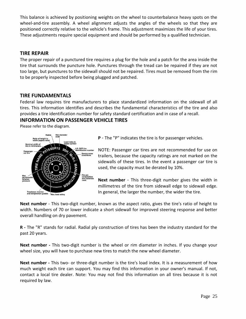
INFORMATION ON PASSENGER VEHICLE TIRES Please refer to the diagram.
P - The "P" indicates the tire is for passenger vehicles. NOTE: Passenger car tires are not recommended for use on trailers, because the capacity ratings are not marked on the sidewalls of these tires. In the event a passenger car tire is used, the capacity must be derated by 10%.
Next number - This three-digit number gives the width in
millimetres of the tire from sidewall edge to sidewall edge. In general, the larger the number, the wider the tire.
Next number - This two-digit number, known as the aspect ratio, gives the tire's ratio of height to width. Numbers of 70 or lower indicate a short sidewall for improved steering response and better overall handling on dry pavement. R - The "R" stands for radial. Radial ply construction of tires has been the industry standard for the past 20 years. Next number - This two-digit number is the wheel or rim diameter in inches. If you change your wheel size, you will have to purchase new tires to match the new wheel diameter. Next number - This two- or three-digit number is the tire's load index. It is a measurement of how much weight each tire can support. You may find this information in your owner's manual. If not, contact a local tire dealer. Note: You may not find this information on all tires because it is not required by law.
Page 26
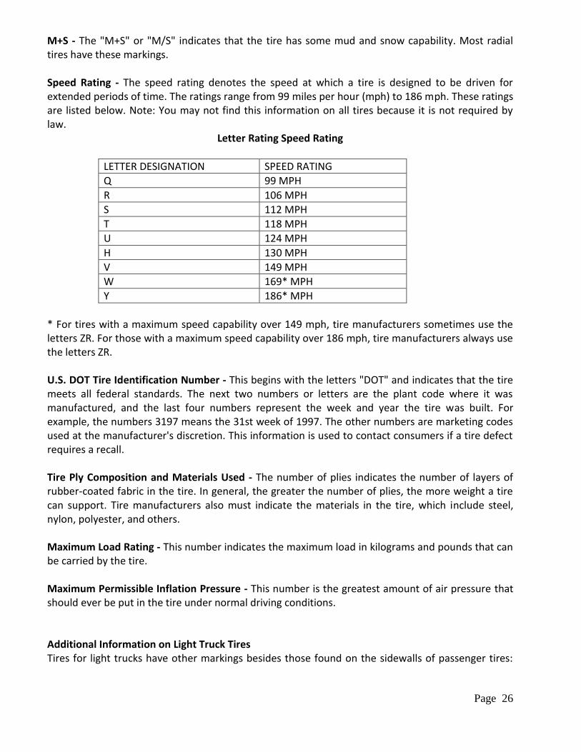
M+S - The "M+S" or "M/S" indicates that the tire has some mud and snow capability. Most radial tires have these markings. Speed Rating - The speed rating denotes the speed at which a tire is designed to be driven for extended periods of time. The ratings range from 99 miles per hour (mph) to 186 mph. These ratings are listed below. Note: You may not find this information on all tires because it is not required by law.
Letter Rating Speed Rating
LETTER DESIGNATION SPEED RATING
Q 99 MPH
R 106 MPH
S 112 MPH
T 118 MPH
U 124 MPH
H 130 MPH
V 149 MPH
W 169* MPH
Y 186* MPH
* For tires with a maximum speed capability over 149 mph, tire manufacturers sometimes use the letters ZR. For those with a maximum speed capability over 186 mph, tire manufacturers always use the letters ZR. U.S. DOT Tire Identification Number - This begins with the letters "DOT" and indicates that the tire meets all federal standards. The next two numbers or letters are the plant code where it was manufactured, and the last four numbers represent the week and year the tire was built. For example, the numbers 3197 means the 31st week of 1997. The other numbers are marketing codes used at the manufacturer's discretion. This information is used to contact consumers if a tire defect requires a recall. Tire Ply Composition and Materials Used - The number of plies indicates the number of layers of rubber-coated fabric in the tire. In general, the greater the number of plies, the more weight a tire can support. Tire manufacturers also must indicate the materials in the tire, which include steel, nylon, polyester, and others. Maximum Load Rating - This number indicates the maximum load in kilograms and pounds that can be carried by the tire. Maximum Permissible Inflation Pressure - This number is the greatest amount of air pressure that should ever be put in the tire under normal driving conditions. Additional Information on Light Truck Tires Tires for light trucks have other markings besides those found on the sidewalls of passenger tires:
Page 27
LT - The "LT" indicates the tire is for light trucks or trailers. ST - An "ST" is an indication the tire is for trailer use only. Max. Load Dual kg (lbs) at kPa (psi) Cold - This information indicates the maximum load and tire pressure when the tire is used as a dual; that is, when four tires are put on each rear axle (a total of six or more tires on the vehicle). Max. Load Single kg (lbs) at kPa (psi) Cold - This information indicates the maximum load and tire pressure when the tire is used as a single. Load Range - This information identifies the tire's load-carrying capabilities and its inflation limits. Weighing methods needed to capture the various weights related to the RV. This would include weights for the following: axles, wheels, hitch or pin (in the case of a trailer) and total weight.
TIRE SAFETY TIPS Preventing Tire Damage
Slow down if you have to go over a pothole or other object in the road.
Do not run over curbs or other foreign objects in the roadway, and try not to strike the curb when parking.
Tire Safety Checklist Check tire pressure regularly (at least once a month), including the spare.
Inspect tires for uneven wear patterns on the tread, cracks, foreign objects, or other signs of wear or trauma.
Remove bits of glass and foreign objects wedged in the tread.
Make sure your tire valves have valve caps.
Check tire pressure before going on a long trip.
Do not overload your vehicle. Check the Tire Information and Loading Placard or User’s Manual for the maximum recommended load for the vehicle.
Steps for Determining Correct Load Limit 1. Locate the statement “The combined weight of occupants and cargo should never exceed
XXX lbs” on your vehicles placard. 2. Determine the combined weight of the driver and passengers that will be riding in your
vehicle. 3. Subtract the combined weight of the driver and passengers from XXX kilograms or XXX
pounds. 4. The resulting figure equals the available amount of cargo and luggage capacity. For example,
if the “XXX” amount equals 1400 lbs. and there will be five 150 lb. passengers in your vehicle, the amount of available cargo and luggage capacity is 650 lbs. (1400-750 (5 x 150) = 650 lbs.)
5. Determine the combined weight of luggage and cargo being loaded on the vehicle. That weight may not safely exceed the available cargo and luggage capacity calculated in Step # 4.
6. If your vehicle will be towing a trailer, load from your trailer will be transferred to your vehicle. Consult this Manual to determine how this reduces the available cargo and luggage capacity of your vehicle.
Page 28
GLOSSARY OF TIRE TERMINOLOGY Accessory weight - The combined weight (in excess of those standard items, which may be replaced) of automatic transmission, power steering, power brakes, power windows, power seats, radio and heater, to the extent that these items are available as factory installed equipment (whether installed or not). Bead - The part of the tire that is made of steel wires, wrapped or reinforced by ply cords and that is shaped to fit the rim. Bead separation - This is the breakdown of the bond between components in the bead. Bias ply tire - A pneumatic tire in which the ply cords that extend to the beads are laid at alternate angles substantially less than 90 degrees to the centerline of the tread. Carcass - The tire structure, except tread and sidewall rubber which, when inflated, bears the load. Chunking - The breaking away of pieces of the tread or sidewall. Cold inflation pressure - The pressure in the tire before you drive. Cord - The strands forming the plies in the tire. Cord separation - The parting of cords from adjacent rubber compounds. Cracking - Any parting within the tread, sidewall, or inner liner of the tire extending to cord material. CT - A pneumatic tire with an inverted flange tire and rim system in which the rim is designed with rim flanges pointed radially inward and the tire is designed to fit on the underside of the rim in a manner that encloses the rim flanges inside the air cavity of the tire. Curb weight - The weight of a motor vehicle with standard equipment including the maximum capacity of fuel, oil, and coolant, and, if so equipped, air conditioning and additional weight optional engine. Extra load tire - A tire designed to operate at higher loads and at higher inflation pressures than the corresponding standard tire. Groove - The space between two adjacent tread ribs. Gross Vehicle Weight Rating (GVWR) - The maximum permissible weight of this fully loaded travel trailer. Gross Axle Weight Rating (GAWR) - The value specified as the load carrying capacity of a single axle system, as measured at the tire-ground interfaces. Hitch Weight - The vertical trailer load supported by the hitch ball.
Page 29
Inner liner - The layer(s) forming the inside surface of a tubeless tire that contains the inflating medium within the tire. Inner liner separation - The parting of the inner liner from cord material in the carcass. Intended outboard sidewall - The sidewall that contains a white-wall bears white lettering or bears manufacturer, brand, and/or model name molding that is higher or deeper than the same molding on the other sidewall of the tire or the outward facing sidewall of an asymmetrical tire that has a particular side that must always face outward when mounted on a vehicle. Light truck (LT) tire - A tire designated by its manufacturer as primarily intended for use on lightweight trucks or multipurpose passenger vehicles. Load rating - The maximum load that a tire is rated to carry for a given inflation pressure. Maximum load rating - The load rating for a tire at the maximum permissible inflation pressure for that tire. Maximum permissible inflation pressure - The maximum cold inflation pressure to which a tire may be inflated. Maximum loaded vehicle weight - The sum of curb weight, accessory weight, vehicle capacity weight, and production options weight. Measuring rim - The rim on which a tire is fitted for physical dimension requirements. Non-pneumatic rim - A mechanical device which, when a non-pneumatic tire assembly incorporates a wheel, supports the tire, and attaches, either integrally or separably, to the wheel center member and upon which the tire is attached. Non-pneumatic spare tire assembly - A non-pneumatic tire assembly intended for temporary use in place of one of the pneumatic tires and rims that are fitted to a passenger car in compliance with the requirements of this standard. Non-pneumatic tire - A mechanical device which transmits, either directly or through a wheel or wheel center member, the vertical load and tractive forces from the roadway to the vehicle, generates the tractive forces that provide the directional control of the vehicle and does not rely on the containment of any gas or fluid for providing those functions. Non-pneumatic tire assembly - A non-pneumatic tire, alone or in combination with a wheel or wheel center member, which can be mounted on a vehicle. Normal occupant weight - This means 68 kilograms (150 lbs.) times the number of occupants specified in the second column of Table I of 49 CFR 571.110. Occupant distribution - The distribution of occupants in a vehicle as specified in the third column of Table I of 49 CFR 571.110.
Page 30
Open splice - Any parting at any junction of tread, sidewall, or inner liner that extends to cord material. Outer diameter - The overall diameter of an inflated new tire. Overall width - The linear distance between the exteriors of the sidewalls of an inflated tire, including elevations due to labelling, decorations, or protective bands or ribs. Pin Weight - The vertical trailer load supported by the king pin of a fifth wheel hitch. Ply - A layer of rubber-coated parallel cords. Ply separation - A parting of rubber compound between adjacent plies. Pneumatic tire - A mechanical device made of rubber, chemicals, fabric and steel or other materials, that, when mounted on an automotive wheel, provides the traction and contains the gas or fluid that sustains the load. Production options weight - The combined weight of those installed regular production options weighing over 2.3 kilograms (5 lbs.) in excess of those standard items which they replace, not previously considered in curb weight or accessory weight, including heavy duty brakes, ride levellers, roof rack, heavy-duty battery, and special trim. Radial ply tire - A pneumatic tire in which the ply cords that extend to the beads are laid at substantially 90 degrees to the centerline of the tread. Recommended inflation pressure - This is the inflation pressure provided by the vehicle manufacturer on the Tire Information label and on the Certification / VIN tag. Reinforced tire - A tire designed to operate at higher loads and at higher inflation pressures than the corresponding standard tire. Rim - A metal support for a tire or a tire and tube assembly upon which the tire beads are seated. Rim diameter - This means the nominal diameter of the bead seat. Rim size designation - This means the rim diameter and width. Rim type designation - This means the industry of manufacturer’s designation for a rim by style or code. Rim width - This means the nominal distance between rim flanges. Section width - The linear distance between the exteriors of the sidewalls of an inflated tire, excluding elevations due to labelling, decoration, or protective bands.
Page 31
Sidewall - That portion of a tire between the tread and bead. Sidewall separation - The parting of the rubber compound from the cord material in the sidewall. Test rim - The rim on which a tire is fitted for testing, and may be any rim listed as appropriate for use with that tire. Tread - That portion of a tire that comes into contact with the road. Tread rib - A tread section running circumferentially around a tire. Tread separation - Pulling away of the tread from the tire carcass. Tread wear indicators (TWI) - The projections within the principal grooves designed to give a visual indication of the degrees of wear of the tread. Vehicle capacity weight - The rated cargo and luggage load plus 68 kilograms (150 lbs.) times the vehicle’s designated seating capacity. Vehicle maximum load on the tire - The load on an individual tire that is determined by distributing to each axle its share of the maximum loaded vehicle weight and dividing by two. Vehicle normal load on the tire - The load on an individual tire that is determined by distributing to each axle its share of the curb weight, accessory weight, and normal occupant weight (distributed in accordance with Table I of CRF 49 571.110) and dividing by 2. Weather side - The surface area of the rim not covered by the inflated tire. Wheel center member - In the case of a non-pneumatic tire assembly incorporating a wheel, a mechanical device which attaches, either integrally or separably, to the non-pneumatic rim and provides the connection between the non-pneumatic rim and the vehicle; or, in the case of a non-pneumatic tire assembly not incorporating a wheel, a mechanical device, which attaches, either integrally or separably, to the non-pneumatic tires and provides the connection between tire and the vehicle. Wheel-holding fixture - The fixture used to hold the wheel and tire assembly securely during testing.
Page 32
ELECTRICAL SYSTEM
Your travel trailer is equipped with 2 electrical systems. The Bigfoot 12V house system and the 110V/120V Electrical System. They operate together to give you electrical power for many different situations.
BIGFOOT 12V HOUSE ELECTRICAL SYSTEM This system generally includes: All 12V interior lighting fixtures and outlets. Fresh water pump 12V accessories Battery Disconnect The 12V batteries will provide power for lighting and other living needs when 110V/120V AC is not available. The house batteries are charged by the towing vehicle’s alternator or by the converter when it is connected to a 100V/120V AC. The 12V battery used must be an RV deep cycle battery. Although this appears the same as an automotive type battery, its design and capabilities are quite different. A deep cycle battery may be fully discharged many times without serious damage providing it is properly recharged immediately after use. For complete information on the use, care and maintenance of your battery, consult the battery Manufacturer’s literature.
110V/120V ELECTRICAL SYSTEM This system provides grounded 110V/120V AC electrical service for appliances such as air conditioners, TV, microwave ovens, etc. Power sources are: The Generator, if equipped The Main Electrical Power Cord (“Shore Power”) The RV is equipped with 25 feet of heavy-duty power cord, which is stored in an exterior compartment. The connector and cord are moulded together to form a weatherproof cable assembly and should not be cut or altered in any way. To use, simply pull the cable from the storage compartment and plug in. To store, feed the cable back in to the hatch and clip down the cover.
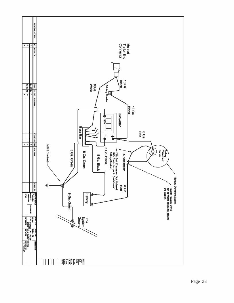
Page 33
Page 34
45 AMP SERVICE 45 amp service is 110-volt service limited to a total of 45 amps of draw. Each appliance in your recreational vehicle is capable of working by itself with this type of service. However, you may not be able to operate all of your appliances at the same time without causing a circuit breaker to blow. The 45 amp power cord may be used with a 15 amp receptacle; however a 45/15amp power adapter will be required. This adapter may be purchased from any RV Outletship. When the power supply cable is plugged in to an outlet the converter will automatically supply all 12V circuits without a drain on the battery; All 12V circuits are protected from overload by automotive type fuses. Reset-able breakers protect all 110V/120V circuits. The converter charger is protected from any power surges by an automotive type fuse.
CAUTION! NEVER REPLACE CIRCUIT BREAKERS OR FUSES OF HIGHER CURRENT RATING THAN THOSE
ORIGINALLY INSTALLED. THIS COULD OVERHEAT THE WIRING AND START A FIRE. A typical component in your recreational vehicle such as a TV will draw only about 1 amp. Other items such as microwaves will draw 10-15 amps when used. Roof air conditioners usually draw the most, up to 15 amps when the compressor is running, when the pump is running and at the start up of the air conditioner. If your trailer has 2 air conditioners, you can only use one air conditioner when hooked up to shore power. The combined draw of the air conditioners along with other items in your trailer, such as the refrigerator, electric water heater, etc. will put you over the 45 amp mark causing a circuit break.
POWER CONVERTER Your travel trailer is equipped with a 110V/120V AC to 12V DC converter, which will automatically switch the load from battery to the converter when the travel trailer is plugged into the 110V/120V shore power source. Power is then supplied from the distribution panel for interior lighting, water heater and furnace. Included in the power converter is a battery charge circuit, which is designed to recharge the RV battery and automatically shut off when the preset required voltage is reached. Some on-board equipment is connected directly to the battery and the charge module will recharge the battery as required.
CAUTION! IF EXCESSIVE LOSS OF BATTERY FLUID IS NOTED CONTACT YOUR OUTLET OR QUALIFIED SERVICE CENTER. A SHORT CIRCUIT OR A DEFECTIVE BATTERY CAN FOOL THE CHARGE MODULE INTO NOT SHUTTING OFF AND BOILING OF THE BATTERY WILL RESULT. ANY
DAMAGE CAUSED TO THE TRAVEL TRAILER AS A RESULT OF A DEFECTIVE BATTERY WILL NOT BE WARRANTABLE BY THE TRAVEL TRAILER MANUFACTURER.
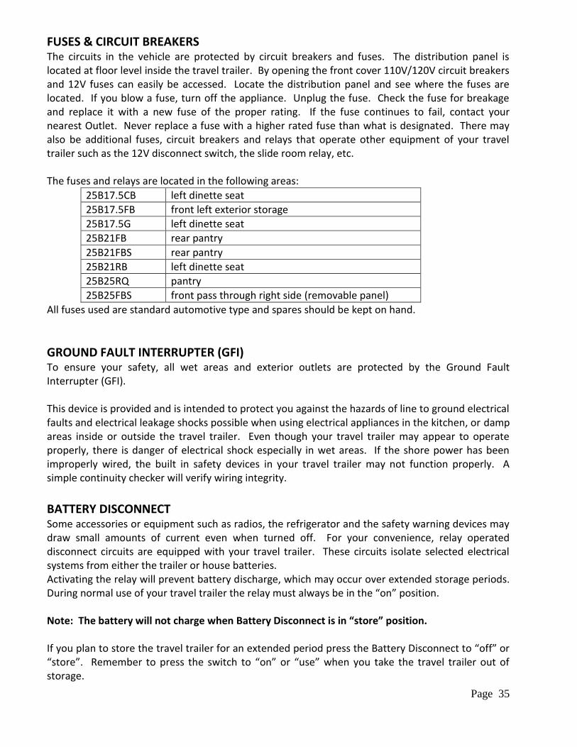
Page 35
FUSES & CIRCUIT BREAKERS The circuits in the vehicle are protected by circuit breakers and fuses. The distribution panel is located at floor level inside the travel trailer. By opening the front cover 110V/120V circuit breakers and 12V fuses can easily be accessed. Locate the distribution panel and see where the fuses are located. If you blow a fuse, turn off the appliance. Unplug the fuse. Check the fuse for breakage and replace it with a new fuse of the proper rating. If the fuse continues to fail, contact your nearest Outlet. Never replace a fuse with a higher rated fuse than what is designated. There may also be additional fuses, circuit breakers and relays that operate other equipment of your travel trailer such as the 12V disconnect switch, the slide room relay, etc. The fuses and relays are located in the following areas:
25B17.5CB left dinette seat
25B17.5FB front left exterior storage
25B17.5G left dinette seat
25B21FB rear pantry
25B21FBS rear pantry
25B21RB left dinette seat
25B25RQ pantry
25B25FBS front pass through right side (removable panel)
All fuses used are standard automotive type and spares should be kept on hand.
GROUND FAULT INTERRUPTER (GFI) To ensure your safety, all wet areas and exterior outlets are protected by the Ground Fault Interrupter (GFI). This device is provided and is intended to protect you against the hazards of line to ground electrical faults and electrical leakage shocks possible when using electrical appliances in the kitchen, or damp areas inside or outside the travel trailer. Even though your travel trailer may appear to operate properly, there is danger of electrical shock especially in wet areas. If the shore power has been improperly wired, the built in safety devices in your travel trailer may not function properly. A simple continuity checker will verify wiring integrity.
BATTERY DISCONNECT Some accessories or equipment such as radios, the refrigerator and the safety warning devices may draw small amounts of current even when turned off. For your convenience, relay operated disconnect circuits are equipped with your travel trailer. These circuits isolate selected electrical systems from either the trailer or house batteries. Activating the relay will prevent battery discharge, which may occur over extended storage periods. During normal use of your travel trailer the relay must always be in the “on” position. Note: The battery will not charge when Battery Disconnect is in “store” position. If you plan to store the travel trailer for an extended period press the Battery Disconnect to “off” or “store”. Remember to press the switch to “on” or “use” when you take the travel trailer out of storage.
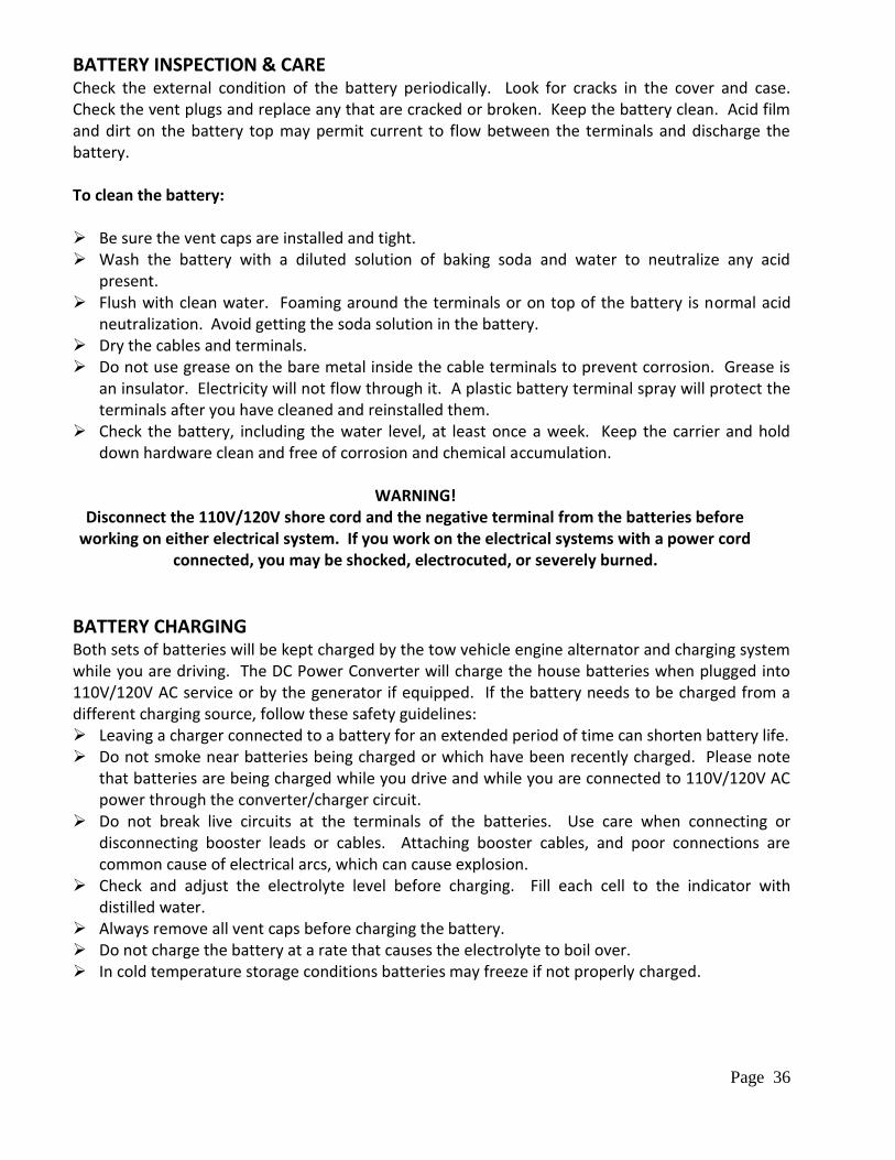
Page 36
BATTERY INSPECTION & CARE Check the external condition of the battery periodically. Look for cracks in the cover and case. Check the vent plugs and replace any that are cracked or broken. Keep the battery clean. Acid film and dirt on the battery top may permit current to flow between the terminals and discharge the battery. To clean the battery: Be sure the vent caps are installed and tight. Wash the battery with a diluted solution of baking soda and water to neutralize any acid
present. Flush with clean water. Foaming around the terminals or on top of the battery is normal acid
neutralization. Avoid getting the soda solution in the battery. Dry the cables and terminals. Do not use grease on the bare metal inside the cable terminals to prevent corrosion. Grease is
an insulator. Electricity will not flow through it. A plastic battery terminal spray will protect the terminals after you have cleaned and reinstalled them.
Check the battery, including the water level, at least once a week. Keep the carrier and hold down hardware clean and free of corrosion and chemical accumulation.
WARNING!
Disconnect the 110V/120V shore cord and the negative terminal from the batteries before working on either electrical system. If you work on the electrical systems with a power cord
connected, you may be shocked, electrocuted, or severely burned.
BATTERY CHARGING Both sets of batteries will be kept charged by the tow vehicle engine alternator and charging system while you are driving. The DC Power Converter will charge the house batteries when plugged into 110V/120V AC service or by the generator if equipped. If the battery needs to be charged from a different charging source, follow these safety guidelines: Leaving a charger connected to a battery for an extended period of time can shorten battery life. Do not smoke near batteries being charged or which have been recently charged. Please note
that batteries are being charged while you drive and while you are connected to 110V/120V AC power through the converter/charger circuit.
Do not break live circuits at the terminals of the batteries. Use care when connecting or disconnecting booster leads or cables. Attaching booster cables, and poor connections are common cause of electrical arcs, which can cause explosion.
Check and adjust the electrolyte level before charging. Fill each cell to the indicator with distilled water.
Always remove all vent caps before charging the battery. Do not charge the battery at a rate that causes the electrolyte to boil over. In cold temperature storage conditions batteries may freeze if not properly charged.
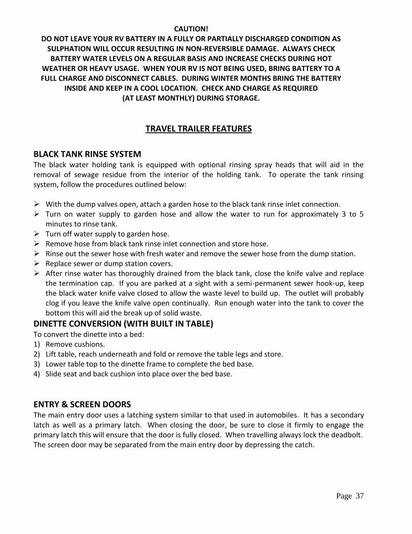
Page 37
CAUTION! DO NOT LEAVE YOUR RV BATTERY IN A FULLY OR PARTIALLY DISCHARGED CONDITION AS
SULPHATION WILL OCCUR RESULTING IN NON-REVERSIBLE DAMAGE. ALWAYS CHECK BATTERY WATER LEVELS ON A REGULAR BASIS AND INCREASE CHECKS DURING HOT
WEATHER OR HEAVY USAGE. WHEN YOUR RV IS NOT BEING USED, BRING BATTERY TO A FULL CHARGE AND DISCONNECT CABLES. DURING WINTER MONTHS BRING THE BATTERY
INSIDE AND KEEP IN A COOL LOCATION. CHECK AND CHARGE AS REQUIRED (AT LEAST MONTHLY) DURING STORAGE.
TRAVEL TRAILER FEATURES
BLACK TANK RINSE SYSTEM The black water holding tank is equipped with optional rinsing spray heads that will aid in the removal of sewage residue from the interior of the holding tank. To operate the tank rinsing system, follow the procedures outlined below: With the dump valves open, attach a garden hose to the black tank rinse inlet connection. Turn on water supply to garden hose and allow the water to run for approximately 3 to 5
minutes to rinse tank. Turn off water supply to garden hose. Remove hose from black tank rinse inlet connection and store hose. Rinse out the sewer hose with fresh water and remove the sewer hose from the dump station. Replace sewer or dump station covers. After rinse water has thoroughly drained from the black tank, close the knife valve and replace
the termination cap. If you are parked at a sight with a semi-permanent sewer hook-up, keep the black water knife valve closed to allow the waste level to build up. The outlet will probably clog if you leave the knife valve open continually. Run enough water into the tank to cover the bottom this will aid the break up of solid waste.
DINETTE CONVERSION (WITH BUILT IN TABLE) To convert the dinette into a bed: 1) Remove cushions. 2) Lift table, reach underneath and fold or remove the table legs and store. 3) Lower table top to the dinette frame to complete the bed base. 4) Slide seat and back cushion into place over the bed base.
ENTRY & SCREEN DOORS The main entry door uses a latching system similar to that used in automobiles. It has a secondary latch as well as a primary latch. When closing the door, be sure to close it firmly to engage the primary latch this will ensure that the door is fully closed. When travelling always lock the deadbolt. The screen door may be separated from the main entry door by depressing the catch.
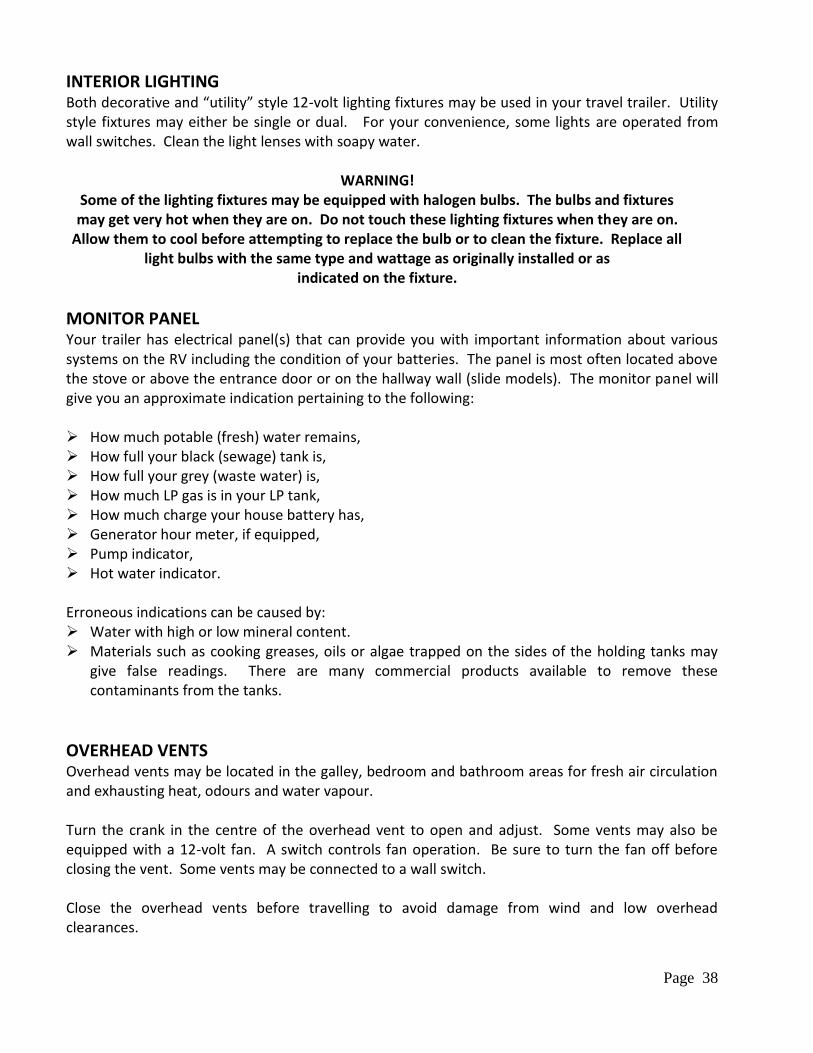
Page 38
INTERIOR LIGHTING Both decorative and “utility” style 12-volt lighting fixtures may be used in your travel trailer. Utility style fixtures may either be single or dual. For your convenience, some lights are operated from wall switches. Clean the light lenses with soapy water.
WARNING!
Some of the lighting fixtures may be equipped with halogen bulbs. The bulbs and fixtures may get very hot when they are on. Do not touch these lighting fixtures when they are on.
Allow them to cool before attempting to replace the bulb or to clean the fixture. Replace all light bulbs with the same type and wattage as originally installed or as
indicated on the fixture.
MONITOR PANEL Your trailer has electrical panel(s) that can provide you with important information about various systems on the RV including the condition of your batteries. The panel is most often located above the stove or above the entrance door or on the hallway wall (slide models). The monitor panel will give you an approximate indication pertaining to the following: How much potable (fresh) water remains, How full your black (sewage) tank is, How full your grey (waste water) is, How much LP gas is in your LP tank, How much charge your house battery has, Generator hour meter, if equipped, Pump indicator, Hot water indicator. Erroneous indications can be caused by: Water with high or low mineral content. Materials such as cooking greases, oils or algae trapped on the sides of the holding tanks may
give false readings. There are many commercial products available to remove these contaminants from the tanks.
OVERHEAD VENTS Overhead vents may be located in the galley, bedroom and bathroom areas for fresh air circulation and exhausting heat, odours and water vapour. Turn the crank in the centre of the overhead vent to open and adjust. Some vents may also be equipped with a 12-volt fan. A switch controls fan operation. Be sure to turn the fan off before closing the vent. Some vents may be connected to a wall switch. Close the overhead vents before travelling to avoid damage from wind and low overhead clearances.
Page 39
The vent may be cleaned from the top of the travel trailer. Use soapy water on the vent cover. The screens may be vacuumed or lightly brushed to remove accumulation of leaves or other debris. Lubricate the gears and mechanism yearly with light, water resistant grease.
SOFA CONVERSION (MANUAL SOFA) Your trailer may be equipped with a sofa that converts into a bed for extra sleeping room. To convert a sofa bed into a bed: 1) Remove sofa bolsters. 2) Lift front of sofa seat up and out. The back of the sofa will drop back and down, as the seat is
pulled outward. To restore the sofa: 1) Lift the front edge of the sofa seat up, and push it back towards the rear. The sofa back will
come up. 2) Push the sofa fully into position and replace the bolsters.
SOFA CONVERSION (ELECTRIC) Your coach may be equipped with an electrical powered sofa that converts into a bed for extra sleeping room. Remove sofa bolsters. The sofa is controlled with a rocker switch.
EXTERIOR STORAGE COMPARTMENTS Exterior storage compartments should accommodate most of your storage needs. All of the storage compartments, except the LP Gas compartment, can be locked. Fire prevention regulations require that the LP Gas tank compartment be unlocked at all times. Please note your travel trailer could be overloaded or out of balance if not properly loaded. Always keep tools and equipment stored in areas where they will not shift while travelling. Whenever possible, place heavy articles in the storage compartments which are low and the
best location for weight distribution. Pack articles carefully in the storage compartments to minimize shifting. If necessary, use straps to prevent movement.
Be sure liquid containers are capped and cannot tip or spill. Secure all glass containers and dishes before travelling Exterior storage compartments may not be water tight in all conditions. Store any articles,
which could be damaged by water inside the travel trailer.
INTERIOR STORAGE The closets and most cabinets have catches along one edge of the door. Pull on the cabinet door handle to open.
Page 40
The same loading considerations apply to interior storage areas as to the exterior storage areas.
WINDOWS Windows in your travel trailer are fixed, slider type or awning style. Open the awning style windows by rotating the knob. Open the slider type window by unlatching the window lock. On your ventilating windows, the frame traps water. During a heavy down pour or washing, water may be seen in the lower portion of the frame. The sloping sill and weep slots allow the water to drain outside. These weep slots must be kept open. If water collects in the bottom channel and over flows, check the weep slots for debris and obstructions and clean as necessary.
VENETIAN BLINDS To raise blinds, release bottom of blind from retainer. Pull straight down on cord and release at desired height. It is not necessary to pull the cord to one side or the other to secure the blind. To lower blinds, pull straight down on the cord slightly and move it about 45 degrees to either the left or right and lower the blind. Stop the blind in mid travel by moving it back to the straight down position. Re-attach the retainers when travelling. To adjust the angle, turn the adjusting rod in either direction
DAY/NIGHT SHADES The Day/Night Shades are dual purpose window covering that provide privacy at night and light control during the day. To operate them, pull down on the lower bar to expose the sheer fabric for light control. For use at night, pull on the upper bar to unfold the privacy curtain. Note: Please do not lift or pull on both bars at the same time.
WIRING DIAGRAMS Because of the many models, floor plans and option variations available, it is beyond the scope of this manual to include wiring diagrams in this manual. In certain situations, specific wiring diagrams may be available to help troubleshoot a problem. If you need specific wiring information please contact your Outlet. Complete wiring diagrams are not available.
Page 41
TRAVEL TRAILER OPTIONS Your unit may be equipped with the following features. Your detailed Outlet invoice may help specify which of the following options are included in your travel trailer.
AM/FM STEREO CD OR CD/DVD PLAYER Your unit may be equipped with either an AM/FM Single CD or CD/DVD player. Stereos operate on 12V DC power. Please consult the specific owner’s manual for operating instructions.
AWNINGS Your travel trailer may be equipped with a self-storing awning and/or slide out cover awnings. Proper use, care and maintenance procedures for awnings are included in the literature provided with the awning. Make sure to clean off all debris as you roll up your awnings. Periodically wash off the awning fabric with a soapy water solution. Long-term exposure to the sun may cause some normal fading over time. Note: Avoid storing awning when wet for any length of time.
EXTERIOR SHOWER A shower fixture may be mounted in the exterior compartment. The water pump must be on or city pressure must be available for the shower to operate.
GENERATOR An onboard LPG generator produces 110V/120V power source to all 110V/120V systems and optional equipment when 110V/120V power sources are not available. To operate your generator, make sure that the breaker on the generator is in the “on” position. Once you have done this, you start the generator by pushing the generator switch. This is located in the monitor panel area. If the generator is slow to start, do not hold the switch in the start position for more than 10 seconds. Release the switch, wait 15 seconds, then try to start again. This will help avoid overheating and damage to the generator starting system. Refer to the specific generator owners’ manual. To stop the generator, hold the switch in the stop position until the engine stops completely. If you release the switch too soon the generator will continue to operate.
STABILIZER JACKS Your vehicle may be equipped with stabilizer jack systems, which are used to level your trailer and to keep it from swaying when parked for camping. Stabilizer jacks are not designed as lifting systems for service access under the trailer. Placement of ANSI approved jack stands under the trailer is necessary prior to entering the underside of any recreational vehicle for service. Due to the varying options contained in stabilizer jack systems, it is recommended that you read the operation manual included with the system installed on your trailer for proper operation procedures.
Page 42
SOLAR PANEL Your travel trailer may be equipped with a solar charger. The solar charging panel installed on the roof of your travel trailer is designed to “trickle charge” the batteries. It is not intended to be a fast charger. It also cannot supply large amounts of current to operate 12V DC electrical equipment. When the sky is clear and under bright sun, the solar panel will keep your batteries “topped up”. Do not try to operate the 12V DC appliances with the output of the solar panel. Please consult the specific owner’s manual for operating instructions.
TELEVISION Your unit may be equipped with an LCD television inside the travel trailer. Please consult the specific owner’s manual for operating instructions.
TV ANTENNA Our travel trailers are equipped with a non-amplified directional antenna with amplified TV boosts.
LP GAS
Liquefied Petroleum gas, often referred to as propane, is a material compound of various hydrocarbons such as propane, propylene, butanes, butylenes or a mixture of them. It is stored in the tanks as liquid under high pressure and vaporizes into a gaseous fuel under the control of a pressure regulator, which reduces pressure to about 6.5 ounces per square inch. This low-pressure LP vapour is then transferred through the gas distribution lines for the use of heat producing appliances such as the furnace, range, water heater and refrigerator. LP gas burns readily and yields a tremendous amount of heat energy. Under proper conditions and careful handling it is safe, economical and ideally suited for use where conventional fuels are not easily utilized. A strong odour similar to sulphur has been added to the gas for safety. Both propane and butane gases are heavier than air and when released flow downwards and tend to fill depressions. Both diffuse and dissipate quickly if adequate ventilation is provided to allow a downward flow.
CAUTION! THIS GAS PIPING SYSTEM IS DESIGNED FOR USE WITH LP GAS ONLY! DO NOT CONNECT
NATURAL GAS TO THIS SYSTEM!
Securely cap inlet when not connected for use. After turning on gas, except after normal cylinder replacement, test gas piping and connections to appliances for leakage with soapy
water or bubble solution. Do not use products that contain ammonia or chlorine.
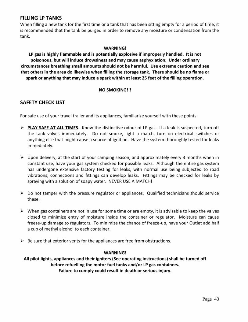
Page 43
FILLING LP TANKS When filling a new tank for the first time or a tank that has been sitting empty for a period of time, it is recommended that the tank be purged in order to remove any moisture or condensation from the tank.
WARNING! LP gas is highly flammable and is potentially explosive if improperly handled. It is not poisonous, but will induce drowsiness and may cause asphyxiation. Under ordinary
circumstances breathing small amounts should not be harmful. Use extreme caution and see that others in the area do likewise when filling the storage tank. There should be no flame or
spark or anything that may induce a spark within at least 25 feet of the filling operation.
NO SMOKING!!!
SAFETY CHECK LIST For safe use of your travel trailer and its appliances, familiarize yourself with these points: PLAY SAFE AT ALL TIMES. Know the distinctive odour of LP gas. If a leak is suspected, turn off
the tank valves immediately. Do not smoke, light a match, turn on electrical switches or anything else that might cause a source of ignition. Have the system thoroughly tested for leaks immediately.
Upon delivery, at the start of your camping season, and approximately every 3 months when in
constant use, have your gas system checked for possible leaks. Although the entire gas system has undergone extensive factory testing for leaks, with normal use being subjected to road vibrations, connections and fittings can develop leaks. Fittings may be checked for leaks by spraying with a solution of soapy water. NEVER USE A MATCH!
Do not tamper with the pressure regulator or appliances. Qualified technicians should service
these. When gas containers are not in use for some time or are empty, it is advisable to keep the valves
closed to minimize entry of moisture inside the container or regulator. Moisture can cause freeze-up damage to regulators. To minimize the chance of freeze-up, have your Outlet add half a cup of methyl alcohol to each container.
Be sure that exterior vents for the appliances are free from obstructions.
WARNING! All pilot lights, appliances and their igniters (See operating instructions) shall be turned off
before refuelling the motor fuel tanks and/or LP gas containers. Failure to comply could result in death or serious injury.
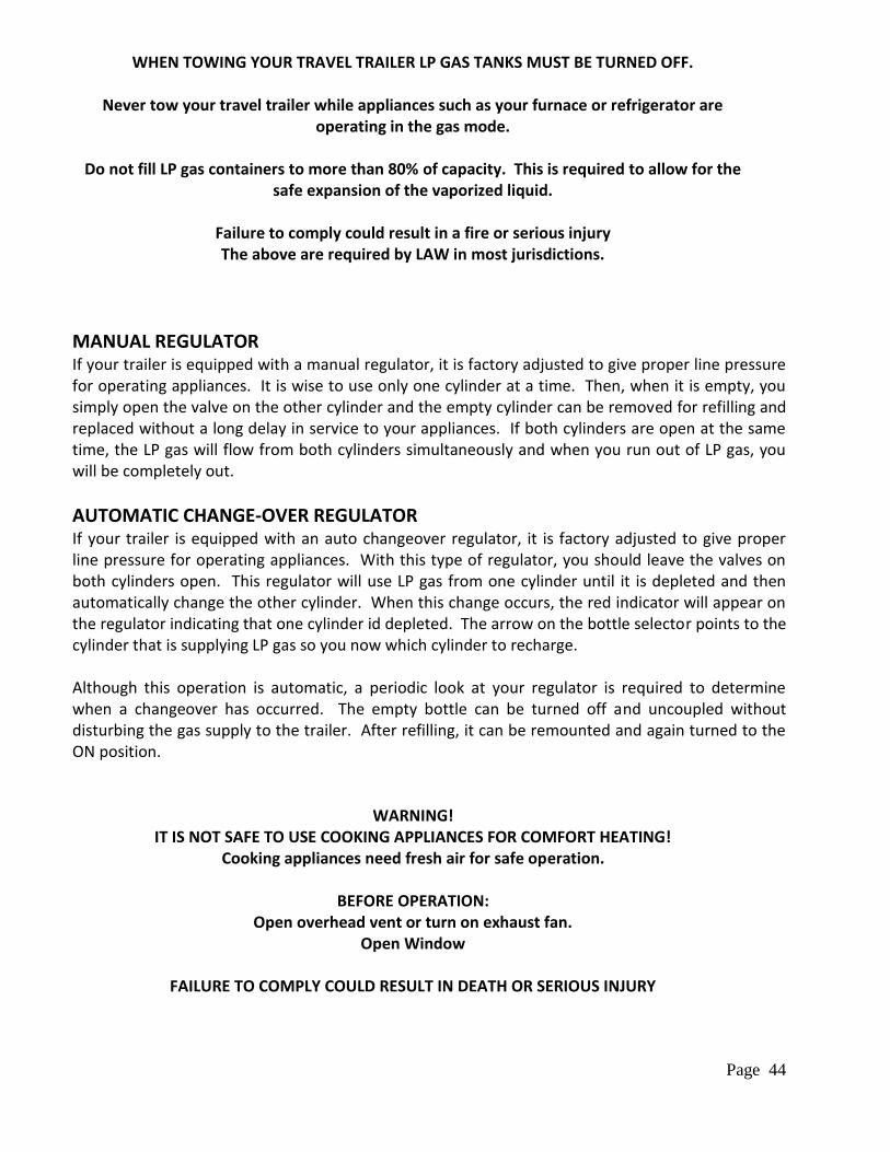
Page 44
WHEN TOWING YOUR TRAVEL TRAILER LP GAS TANKS MUST BE TURNED OFF.
Never tow your travel trailer while appliances such as your furnace or refrigerator are operating in the gas mode.
Do not fill LP gas containers to more than 80% of capacity. This is required to allow for the
safe expansion of the vaporized liquid.
Failure to comply could result in a fire or serious injury The above are required by LAW in most jurisdictions.
MANUAL REGULATOR If your trailer is equipped with a manual regulator, it is factory adjusted to give proper line pressure for operating appliances. It is wise to use only one cylinder at a time. Then, when it is empty, you simply open the valve on the other cylinder and the empty cylinder can be removed for refilling and replaced without a long delay in service to your appliances. If both cylinders are open at the same time, the LP gas will flow from both cylinders simultaneously and when you run out of LP gas, you will be completely out.
AUTOMATIC CHANGE-OVER REGULATOR If your trailer is equipped with an auto changeover regulator, it is factory adjusted to give proper line pressure for operating appliances. With this type of regulator, you should leave the valves on both cylinders open. This regulator will use LP gas from one cylinder until it is depleted and then automatically change the other cylinder. When this change occurs, the red indicator will appear on the regulator indicating that one cylinder id depleted. The arrow on the bottle selector points to the cylinder that is supplying LP gas so you now which cylinder to recharge. Although this operation is automatic, a periodic look at your regulator is required to determine when a changeover has occurred. The empty bottle can be turned off and uncoupled without disturbing the gas supply to the trailer. After refilling, it can be remounted and again turned to the ON position.
WARNING!
IT IS NOT SAFE TO USE COOKING APPLIANCES FOR COMFORT HEATING! Cooking appliances need fresh air for safe operation.
BEFORE OPERATION:
Open overhead vent or turn on exhaust fan. Open Window
FAILURE TO COMPLY COULD RESULT IN DEATH OR SERIOUS INJURY
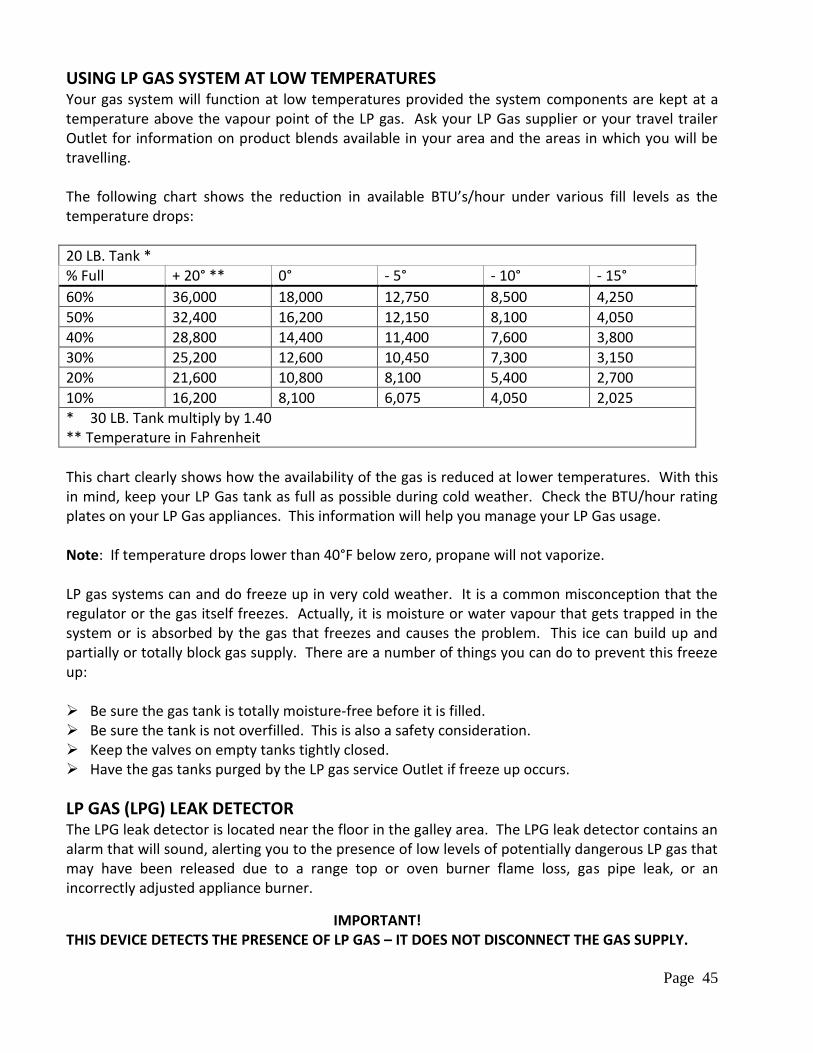
Page 45
USING LP GAS SYSTEM AT LOW TEMPERATURES Your gas system will function at low temperatures provided the system components are kept at a temperature above the vapour point of the LP gas. Ask your LP Gas supplier or your travel trailer Outlet for information on product blends available in your area and the areas in which you will be travelling. The following chart shows the reduction in available BTU’s/hour under various fill levels as the temperature drops:
20 LB. Tank * % Full + 20° ** 0° - 5° - 10° - 15°
60% 36,000 18,000 12,750 8,500 4,250
50% 32,400 16,200 12,150 8,100 4,050
40% 28,800 14,400 11,400 7,600 3,800
30% 25,200 12,600 10,450 7,300 3,150
20% 21,600 10,800 8,100 5,400 2,700
10% 16,200 8,100 6,075 4,050 2,025
* 30 LB. Tank multiply by 1.40 ** Temperature in Fahrenheit
This chart clearly shows how the availability of the gas is reduced at lower temperatures. With this in mind, keep your LP Gas tank as full as possible during cold weather. Check the BTU/hour rating plates on your LP Gas appliances. This information will help you manage your LP Gas usage. Note: If temperature drops lower than 40°F below zero, propane will not vaporize. LP gas systems can and do freeze up in very cold weather. It is a common misconception that the regulator or the gas itself freezes. Actually, it is moisture or water vapour that gets trapped in the system or is absorbed by the gas that freezes and causes the problem. This ice can build up and partially or totally block gas supply. There are a number of things you can do to prevent this freeze up: Be sure the gas tank is totally moisture-free before it is filled. Be sure the tank is not overfilled. This is also a safety consideration. Keep the valves on empty tanks tightly closed. Have the gas tanks purged by the LP gas service Outlet if freeze up occurs.
LP GAS (LPG) LEAK DETECTOR The LPG leak detector is located near the floor in the galley area. The LPG leak detector contains an alarm that will sound, alerting you to the presence of low levels of potentially dangerous LP gas that may have been released due to a range top or oven burner flame loss, gas pipe leak, or an incorrectly adjusted appliance burner.
IMPORTANT! THIS DEVICE DETECTS THE PRESENCE OF LP GAS – IT DOES NOT DISCONNECT THE GAS SUPPLY.
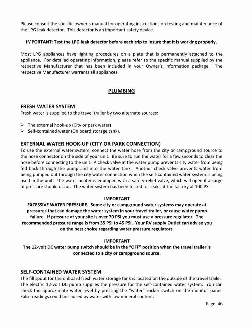
Page 46
Please consult the specific owner’s manual for operating instructions on testing and maintenance of the LPG leak detector. This detector is an important safety device.
IMPORTANT: Test the LPG leak detector before each trip to insure that it is working properly. Most LPG appliances have lighting procedures on a plate that is permanently attached to the appliance. For detailed operating information, please refer to the specific manual supplied by the respective Manufacturer that has been included in your Owner’s Information package. The respective Manufacturer warrants all appliances.
PLUMBING
FRESH WATER SYSTEM Fresh water is supplied to the travel trailer by two alternate sources: The external hook-up (City or park water) Self-contained water (On board storage tank).
EXTERNAL WATER HOOK-UP (CITY OR PARK CONNECTION) To use the external water system, connect the water hose from the city or campground source to the hose connector on the side of your unit. Be sure to run the water for a few seconds to clear the hose before connecting to the unit. A check valve at the water pump prevents city water from being fed back through the pump and into the water tank. Another check valve prevents water from being pumped out through the city water connection when the self-contained water system is being used in the unit. The water heater is equipped with a safety-relief valve, which will open if a surge of pressure should occur. The water system has been tested for leaks at the factory at 100 PSI.
IMPORTANT EXCESSIVE WATER PRESSURE. Some city or campground water systems may operate at pressures that can damage the water system in your travel trailer, or cause water pump
failure. If pressure at your site is over 70 PSI you must use a pressure regulator. The recommended pressure range is from 35 PSI to 45 PSI. Your RV supply Outlet can advise you
on the best choice regarding water pressure regulators.
IMPORTANT The 12-volt DC water pump switch should be in the “OFF” position when the travel trailer is
connected to a city or campground source.
SELF-CONTAINED WATER SYSTEM The fill spout for the onboard fresh water storage tank is located on the outside of the travel trailer. The electric 12-volt DC pump supplies the pressure for the self-contained water system. You can check the approximate water level by pressing the “water” rocker switch on the monitor panel. False readings could be caused by water with low mineral content.
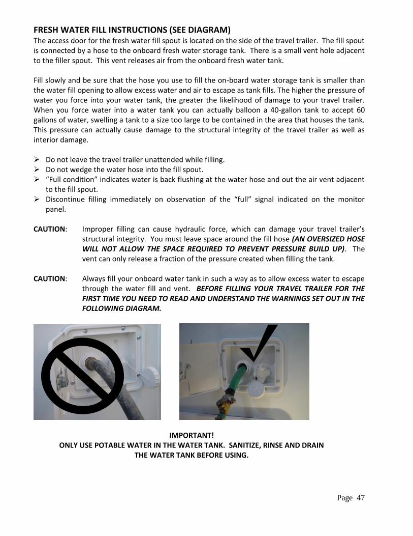
Page 47
FRESH WATER FILL INSTRUCTIONS (SEE DIAGRAM) The access door for the fresh water fill spout is located on the side of the travel trailer. The fill spout is connected by a hose to the onboard fresh water storage tank. There is a small vent hole adjacent to the filler spout. This vent releases air from the onboard fresh water tank. Fill slowly and be sure that the hose you use to fill the on-board water storage tank is smaller than the water fill opening to allow excess water and air to escape as tank fills. The higher the pressure of water you force into your water tank, the greater the likelihood of damage to your travel trailer. When you force water into a water tank you can actually balloon a 40-gallon tank to accept 60 gallons of water, swelling a tank to a size too large to be contained in the area that houses the tank. This pressure can actually cause damage to the structural integrity of the travel trailer as well as interior damage. Do not leave the travel trailer unattended while filling. Do not wedge the water hose into the fill spout. “Full condition” indicates water is back flushing at the water hose and out the air vent adjacent
to the fill spout. Discontinue filling immediately on observation of the “full” signal indicated on the monitor
panel. CAUTION: Improper filling can cause hydraulic force, which can damage your travel trailer’s
structural integrity. You must leave space around the fill hose (AN OVERSIZED HOSE WILL NOT ALLOW THE SPACE REQUIRED TO PREVENT PRESSURE BUILD UP). The vent can only release a fraction of the pressure created when filling the tank.
CAUTION: Always fill your onboard water tank in such a way as to allow excess water to escape
through the water fill and vent. BEFORE FILLING YOUR TRAVEL TRAILER FOR THE FIRST TIME YOU NEED TO READ AND UNDERSTAND THE WARNINGS SET OUT IN THE FOLLOWING DIAGRAM.
IMPORTANT! ONLY USE POTABLE WATER IN THE WATER TANK. SANITIZE, RINSE AND DRAIN
THE WATER TANK BEFORE USING.
Page 48
SANITIZING THE FRESH WATER SYSTEM The following procedures are recommended to ensure complete sanitization of your potable water system. This applies to a new system, one that may have become contaminated or one that has not been used for a period of time. 1) Prepare a solution of ¼ cup household liquid chlorine bleach (5% sodium hypochlorite) to one
gallon of water. This solution will treat 15 gallons of fresh water. You will need to increase solution proportions to the tank capacity of your travel trailer.
2) Close drain valves and faucets; pour chlorine solution into the fresh water tank filler spout. Fill
tank completely with fresh water. 3) Turn water pump switch “ON” be sure you have 12V DC power. Open all faucets individually
until water flows steadily and you detect a distinct odour of chlorine – then turn faucets off. Do not forget the hot water faucets. This will purge any air from the lines.
4) Refill the fresh water tank to “full” and wait 3 to 4 hours.
5) Drain the entire system by opening all water tank valves, faucets and plumbing line drain valves.
6) Rinse the system with fresh water, close drain valves, refill the water tanks with fresh water and repeat the steps set out in step 3 (omitting the chlorine solution). Let the fresh water flow through the system for several minutes to rinse out the chlorine solution.
7) After you finish flushing the fresh water system, drain the entire system by repeating the steps set out in step 5. You can now close the tank valve, faucets and drain valves and fill the tank with fresh water. The system is now ready to use.
To remove any excessive chlorine taste or odour that may remain in the potable water system, prepare a solution of 1 quart vinegar to 5 gallons of water. Allow this solution to agitate in the tank through vehicle motion. Drain tank and rinse again with fresh water as set out in step 5.
ELECTRIC 12-VOLT DC WATER PUMP The onboard fresh water system is pressurized by a self-priming 12V DC water pump. The water pump operates automatically when the water pump power switch is in the “ON” position and a faucet or valve is opened. Turn the water pump “ON” to pressurize the system. When a faucet is opened after the initial filling of the tank, the water may sputter for a few seconds. This is normal and is not cause for concern. In the “ON” position the water pump delivers water to the water heater and faucets and maintains a positive pressure throughout the system.
IMPORTANT! It is recommended to turn the water pump switch “OFF”
whenever you are away from the travel trailer.
Page 49
IMPORTANT! Do not run the water pump without water in the system. The water pump can be found in the following locations:
25B17.5CB under fridge compartment
25B17.5FB Exterior, driver’s side (middle/center) access door
25B17.5G left outside access door
25B21FB forward dinette seat
25B21FBS forward dinette seat
25B21RB lower galley compartment
25B25RQ front dinette seat
25B25FBS under galley
WINTERIZING AND DRAINING THE WATER SYSTEM Protecting the plumbing system in the travel trailer is the most important aspect of long-term winter storage. The winterizing valves are located by the 12V water pump. 1) Drain the fresh water tank by opening the fresh water tank drain valve located in the following
locations. Leave valve open.
25B17.5CB rear left outside storage
25B17.5FB exterior, driver’s side (middle/center) access door
25B17.5G rear left outside storage
25B21FB front left outside storage
25B21FBS front left outside storage
25B21RB rear left outside storage
25B25RQ in front of left tire
25B25FBS winterize under galley, drain fresh tank outside left, behind rear wheel(belly pan)
2) Open the safety valve on the water heater by lifting up the lever on the relief valve. 3) Drain the water heater by removing the drain plug at the bottom of the water heater. 4) Both of these are located behind the access door on the exterior of the travel trailer. Please
refer to your water heater manual for more information on winterizing (flushing) your water heater. Turn the water heater bypass valves to the winterize position. (See the following diagram).
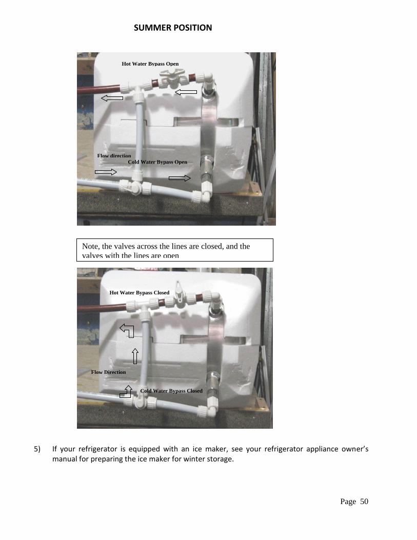
Page 50
5) If your refrigerator is equipped with an ice maker, see your refrigerator appliance owner’s
manual for preparing the ice maker for winter storage.
Hot Water Bypass Closed
Cold Water Bypass Closed
Flow Direction
Hot Water Bypass Open
Cold Water Bypass Open
Flow direction
WINTER POSITION
Note, the valves across the lines are closed, and the
valves with the lines are open
SUMMER POSITION
Page 51
6) To avoid contamination, close fresh water drain valve after tank has been drained. Insert the potable antifreeze pickup tube, located near the water pump, into the jug of potable antifreeze; turn the valve in line with the tube.
7) Turn the water pump switch to the ON position. Starting at the kitchen faucet, turn on the cold-water faucet until the potable antifreeze runs from the faucet, turn off faucet. Turn on hot water faucet until the potable antifreeze runs from the faucet, turn off faucet. Repeat these steps with the Bathroom faucets and with exterior shower (if equipped) until the potable antifreeze runs through the faucets, turn off faucets. Finally hold the flush lever on the toilet until the potable antifreeze runs through the toilet.
8) Drain the wastewater holding tank. 9) Turn off water pump; remove antifreeze pickup tube from antifreeze container and store. 10) Pour remaining potable antifreeze into kitchen, vanity and shower drains. Open all faucets
and leave open to relieve pressure.
WATER HEATER BYPASS SYSTEM
WARNING! DO NOT USE ETHYLENE GLYCOL BASE (AUTOMOTIVE TYPE) ANTIFREEZE IN THE
FRESH WATER SYSTEM.
HOLDING TANKS The waste water system in your travel trailer is made up of sinks, tubs, toilet, plumbing drain, vent lines, “grey water” holding tank and a “black water” holding tank. The holding tanks make the system completely self-contained and allow you to dispose of wastewater at your convenience. A flexible sewer hose is required to connect the holding tank outlet to the inlet of an approved wastewater dump station or sewer system. The drain plumbing is very similar to that used in your home. The system is trapped and vented to prevent waste gases from backing up into the travel trailer. The drain plumbing is durable and resistant to most chemicals. The toilet is mounted on the black water tank and flushes directly into it. The holding tanks terminate in a valve arrangement that permits dumping each tank separately from each other. The valves are called “knife valves”. A blade closes the opening in the sewer drainpipes. The blade is connected to a “T” handle that is pulled to release the content of the tank(s). During self-containment use, the sewer line is securely capped to prevent leakage of waste material onto the ground. DO NOT PULL THE HOLDING TANK KNIFE VALVE OPEN WHEN THE PROTECTIVE CAP IS INSTALLED ON THE PIPE. Always ensure that the tank is emptied into an acceptable sewer inlet or dump station.
WARNING! HOLDING TANKS ARE ENCLOSED SEWER SYSTEMS AND MUST BE DRAINED INTO AN
APPROVED DUMP STATION. BOTH TOILET AND GREY WATER HOLDING TANKS MUST BE DRAINED AND THOROUGHLY RINSED REGULARILY TO PREVENT ACCUMULATION OF TOXIC
MATERIALS.
Page 52
It is recommended that you only dump the holding tanks when they are at least ¾ full. If necessary, fill the tanks with water to ¾ full. This provides sufficient water to ensure complete flushing of waste material into the sewer line.
DUMPING THE HOLDING TANKS 1) First, make sure that dump valve is closed.
2) Remove the sewer drain cap, attach the sewer adapter and drain hose to the dump valve drain
outlet. Place the other end of the drain hose into the sewer or dump station inlet. Push the hose far enough into the opening to firmly secure the hose. In some cases, adapters may be necessary between the line and the inlet.
3) Arrange the sewer hose so it slopes evenly and is supported to maintain the slope to the dump station inlet.
4) Dump the black water holding tank first. Grasp the handle of the black water 3”knife valve firmly and slide the valve open with a quick steady pull.
IMPORTANT: always open the dump valve with a quick jerk to give the desired flushing effect.
5) Allow enough time for the tank to drain completely. Rinse and flush the tank and drain hose
thoroughly through the toilet using a water hose for approximately 5 minutes. When the tank flow stops, push the handle in to close the valve. Add enough water to cover the bottom of the tank.
6) When using a sewer hook-up system in a park, it is recommended to keep the dump valve closed on the black water tank until it is full. This will help prevent accumulation of waste material that could clog the system.
7) To dump the grey water tank repeat the steps above using the smaller knife valve. The grey water knife valve may be left open in a semi-permanent hook-up.
IMPORTANT: Do not dump both tanks at the same time. Also, it is recommended that you add
several gallons of water to each holding tank to thoroughly rinse the tanks and drain the hose. If solids become lodged in the tank add water to the tank and drive with the unit a short distance.
The vibration and motion should dislodge the solids. If an obstruction should remain, contact your Outlet or RV supply store for a suitable cleaning compound.
WARNING!
SEWER DRAIN CAP MUST ALWAYS BE SECURELY IN PLACE WHILE THE VEHICLE IS IN MOTION
PLEASE PRACTICE GOOD HOUSEKEEPING WHEN DRAINING WASTE AT A CAMPSITE OR DISPOSAL STATION. LEAVE THE SITE IN GOOD ORDER.
Page 53
HOLDING TANK CARE & MAINTENANCE 1) Keep the black water knife valve closed. Fill tank to at least ¾ full before dumping. Be sure to
cover the tank bottom with water after dumping. 2) Use only toilet tissue formulated for the use in septic tank or RV sanitation systems. 3) Keep both knife valves closed and the drain cap tightly in place when using the system on the
road. 4) Do not put facial tissue, ethylene glycol-based or other automotive anti-freeze, sanitary napkins,
or household toilet cleaners in the holding tanks. 5) Always store your unit with a good quality non-formaldehyde sanitizing solution.
TOILET The RV toilet operates in a similar manner to a household type toilet except it is designed to flush using a minimum amount of water. Please consult the specific owner’s manual for operating instructions.
APPLIANCES
The kitchen in your Travel trailer is arranged for compact efficiency and convenience. All appliances are easy to care for and designed to leave more time for recreation and fun!!
ALL APPLIANCES HAVE THEIR OWN MANUAL SUPPLIED BY THEIR MANUFACTURER GIVING DETAILED INSTRUCTION. STUDY THESE MANUALS CAREFULLY BEFORE OPERATING OR
ADJUSTING THE APPLIANCES. THESE MANUALS ARE LOCATED IN YOUR OWNER’S INFORMATION PACKAGE.
WARNING!
THE HOT WATER HEATER AND FURNACE USE LP GAS AS FUEL AND IN THE COURSE OF NORMAL OPERATION HAVE PARTS/SURFACES THAT BECOME VERY HOT AND ALSO EMIT COMBUSTION
GASES. BE CAREFUL TO ALWAYS FOLLOW MANUFACTUER’S RECOMMENDATIONS ON VENTILATION AND DO NOT TOUCH THE AIR EXHAUST PORTS OR ALLOW ANY MATERIAL TO COVER THEM OR EVEN COME IN CONTACT WITH EITHER THE INTAKE OR EXHAUST OF THESE
APPLIANCES.
WHENEVER YOU OR SOMEONE IN YOUR VEHICLE SMELLS LP GAS, TAKE PRECAUTIONS AS OUTLINED EARLIER IN THIS MANUAL.
FANTASTIC FAN The fantastic fan operates on 12V DC power. The ceiling fan used in your coach is designed to ventilate the interior when cooking or if the use of your air conditioner is not desired. If used properly the roof fan can cool the interior by as much as 15 degrees within a short period of time. When used in the exhaust mode, the fan pulls hot air from high inside the coach and will pull fresh air from an open window. A built-in thermostat controls the fan. Please consult the respective owner’s manual for operating instructions.
Page 54
FURNACE The furnace is a forced air unit fuelled by LP gas and electronically powered by 12V DC power. Locate the comfort control centre and turn to “ON”. Using “MODE” button, select furnace mode and select desired temperature. Be sure all heat registers are open and free of obstructions to prevent the furnace from cycling due to excessive heat build-up in the furnace chamber. The furnace ignition is powered by your 12-volt battery system. If the system battery is low, the furnace blower will come on, however the furnace will not ignite. Make sure you have sufficient battery power before operating the furnace. To stop the furnace, turn “OFF” the comfort control centre.
WARNING!
DO NOT SUPPLEMENT THE FURNACE WITH ANY PORTABLE FUEL-BURNING APPLIANCE FOR HEATING THE INTERIOR OF THE TRAVEL TRAILER. THESE APPLIANCES ARE NOT SAFE;
ASPHYXIATION/CARBON MONOXIDE POISONING IS POSSIBLE IN ANY SMALL WELL-SEALED SPACE.
MICROWAVE OVEN Your vehicle may be equipped with a microwave oven installed in an overhead cabinet. The microwave is no different than the microwave you may have in your home. The microwave oven operates on 110V/120V AC power and should never be used while travelling down the road. Read over the microwave oven’s owner’s manual to find all the information on its operation and cleaning. Be sure to turn on the 3 position switch located on the galley end. If your vehicle is equipped with a gas, electric water heater, you will find a 3-position switch located in the lower galley cabinet. Set this switch to the microwave position.
POWER RANGE EXHAUST HOOD Your vehicle will be equipped with a power range exhaust hood. It is located above the range burner and operates on 12V DC power.
RANGE (STOVE TOP/OVEN)
WARNING!
Do Not Operate This Appliance Unless The Privacy Curtain Is Secured. Failure To Comply Could Result In Fire Or Serious Injury!
WARNING! IT IS NOT SAFE TO USE COOKING APPLIANCES FOR COMFORT HEATING!
Cooking appliances need fresh air for safe operation.
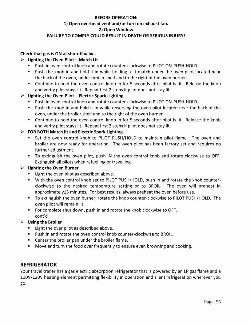
Page 55
BEFORE OPERATION: 1) Open overhead vent and/or turn on exhaust fan.
2) Open Window FAILURE TO COMPLY COULD RESULT IN DEATH OR SERIOUS INJURY!
Check that gas is ON at shutoff valve. Lighting the Oven Pilot – Match Lit
Push in oven control knob and rotate counter-clockwise to PILOT ON-PUSH-HOLD. Push the knob in and hold it in while holding a lit match under the oven pilot located near
the back of the oven, under broiler shelf and to the right of the oven burner. Continue to hold the oven control knob in for 5 seconds after pilot is lit. Release the knob
and verify pilot stays lit. Repeat first 2 steps if pilot does not stay lit. Lighting the Oven Pilot – Electric Spark Lighting
Push in oven control knob and rotate counter-clockwise to PILOT ON-PUSH-HOLD. Push the knob in and hold it in while observing the oven pilot located near the back of the
oven, under the broiler shelf and to the right of the oven burner Continue to hold the oven control knob in for 5 seconds after pilot is lit. Release the knob
and verify pilot stays lit. Repeat first 2 steps if pilot does not stay lit. FOR BOTH Match lit and Electric Spark Lighting
Set the oven control knob to PILOT PUSH/HOLD to maintain pilot flame. The oven and broiler are now ready for operation. The oven pilot has been factory set and requires no further adjustment.
To extinguish the oven pilot, push IN the oven control knob and rotate clockwise to OFF. Extinguish all pilots when refuelling or travelling.
Lighting the Oven Burner Light the oven pilot as described above. With the oven control knob set to PILOT PUSH/HOLD, push in and rotate the knob counter-
clockwise to the desired temperature setting or to BROIL. The oven will preheat in approximately15 minutes. For best results, always preheat the oven before use.
To extinguish the oven burner, rotate the knob counter-clockwise to PILOT PUSH/HOLD. The oven pilot will remain lit.
For complete shut down, push in and rotate the knob clockwise to OFF. cont’d
Using the Broiler Light the over pilot as described above. Push in and rotate the oven control knob counter-clockwise to BROIL. Center the broiler pan under the broiler flame. Move and turn the food over frequently to ensure even browning and cooking.
REFRIGERATOR Your travel trailer has a gas electric absorption refrigerator that is powered by an LP gas flame and a 110V/120V heating element permitting flexibility in operation and silent refrigeration wherever you go.
Page 56
For trouble free, uninterrupted operation, it is important that the user understand the refrigerators operation and certain conditions that must be met. The freezing unit uses heat as a source of power. The heat generated either by gas flame or electricity circulates the refrigerant in the form of a vapour up through the condenser where it is changed to a liquid. The liquid flows down through the evaporator on its way back to the vapour generator completing the cycle. When the liquid passes through the evaporator it is again changed into a vapour by heat absorbed by the food and cabinet area. This heat laden vapour can be trapped or partially trapped when the refrigerator is not level, which will result in a partial or total loss of refrigeration. Therefore the refrigerator must be fairly level to operate on either gas or electricity. Parking level enough to sleep comfortably should do it. The refrigerator in your travel trailer has electronic ignition. The controls are easily accessible and located above the freezer compartment door. 12V DC power must be available for any selected mode of operation. The refrigerator is equipped with a humidity switch. Set it to OFF if you are not going to be using the Travel trailer for 10 days or longer. This will help reduce battery drainage. Ensure door is left in open position when not in use.
ROOF MOUNTED AIR CONDITIONER The air conditioner operates on electrical power from either a shore line or an optional generator, and is designed for cooling your travel trailer. Some models include an optional heating element, which is adequate for removing that early morning chill. An adequate source of 110V/120V AC power is required and when registering at a campsite should advise them that you require an outlet with the required capacity. Be sure to turn on the circuit breaker located on the power converter. Air conditioners (AC) are capable of cooling air in a maximum of 18oF to 22oF degrees in a 50% humidity environment. As the humidity goes up, the cooling difference goes down. If the temperature inside your coach is 100oF degrees when you turn on the AC it will only put out 80oF degrees. Eventually the air inside the coach will cool, and as it cools the air put out by the AC will cool also. However, when starting out at 100oF degrees, this cooling could take several hours before it reaches your desired temperature. If you know the weather will be hot, turn on your AC early. The two most common complaints with roof AC’s are they won’t turn on at all, or when they do turn on, they won’t put out cold air. If the unit won’t turn on, you may have a problem with something other then the AC. Make sure you have sufficient power to run each AC you plan on using. If your power source has only 30-amp service, you can run only one (1) AC at one time. Using an adapter to plug in your 50-amp cord to a 30-amp service doesn’t allow the use of both AC’s. Most AC’s require a minimum of 13 amps to operate properly. Although amperage of two AC’s running at the same time doesn’t add up to 30 amps, other components in the coach, such as the converter, refrigerator, (VCR, DVD draw amps just by being plugged in), etc., draw enough amperage to push the total amp load over the 30 amp mark.
Page 57
WATER HEATER The water heater operates on LP gas or 110V, if so equipped. Before using the water heater read the owner’s manual supplied by the Manufacturer of the water heater for complete understanding of how to safely light and use the water heater as intended by the Manufacturer of the appliance. The LPG ignition for the water heater will be found in the kitchen/bathroom cabinet face.
IMPORTANT: Before turning on the water heater confirm that the water heater is filled with water. Be sure that the water heater bypass valves are not in the bypass position.
Note: Shut heater off before draining water.
EACH LP GAS APPLIANCE HAS LIGHTING PROCEDURES ON A PLATE THAT IS PERMANENTLY ATTACHED TO THE APPLIANCE.
EFFECTS OF LONG TERM OCCUPANCY
Your travel trailer was designed primarily for recreational use and short-term occupancy. If you expect to occupy the travel trailer for an extended period, be prepared to deal with condensation and the humid conditions that may be encountered. The relatively small volume and tight compact construction of a modern recreational vehicle means that the normal living activities of even a few occupants will lead to rapid moisture saturation, especially in cold weather. Just as moisture collects on a glass of cold water during humid weather, moisture can condense on the inside surfaces of your travel trailer during use in cool weather, when the relative humidity of interior air is high. Estimates indicate that a family of 4 can vaporize up to 3 gallons of water daily through breathing, cooking, bathing and washing. Unless this water vapour is carried outside through ventilation or condensed by a dehumidifier, it will condense on the inside of the windows and walls as moisture, or in cold weather as frost or ice. It may also condense out of sight within the walls or the ceiling where it will manifest itself as warped or stained panels. Appearance of these conditions may indicate a serious condensation problem. When you recognize the signs of excessive moisture and condensation in your travel trailer you should take actions to minimize their effects.
Important Note Your travel trailer is not designed to be used as permanent housing. Use of this product for long-
term or permanent occupancy may lead to premature deterioration of the structure, interior finishes, fabrics, carpeting and drapes. Damage or deterioration due to long-term occupancy may not be considered normal, and may under the terms of the warranty, constitutes misuse, abuse or
neglect, and may therefore reduce your warranty protection.
Page 58
VENTILATION & MOISTURE CONTROL You can reduce interior moisture condensation by taking the following steps:
Ventilate With Outside Air Partially open one or more roof vents and one or more windows to provide circulation of outside air into the interior. While this ventilation may increase furnace-heating load during cold weather, it will greatly reduce water condensation. Even when it is raining or snowing ventilation air from outside will be far drier than interior air and will effectively reduce condensation inside the travel trailer.
Minimize Moisture Released Inside the Travel Trailer Run the range vent fan when cooking and the bathroom vent fan (or open the bath vent) when bathing to carry water vapour out of the travel trailer. Avoid making steam from excessive boiling or use of hot water. Remove water or snow from shoes before entering to avoid soaking the carpet. Avoid drying overcoats and other clothes inside the travel trailer.
WARNING! DO NOT HEAT THE TRAVEL TRAILER INTERIOR WITH THE RANGE OR OVEN
In addition to the hazards of toxic fumes and oxygen depletion, open flames add moisture to the interior air, increasing condensation. Do not use an air humidifier inside the travel trailer. Water put into the air by the humidifier will greatly increase condensation.
Ventilate Closets & Cabinets During prolonged use in very cold weather, leave cabinet and closet doors partially open to warm and ventilate the interiors of storage cabinets built against exterior walls. The airflow will warm the exterior wall surface, reducing or eliminating condensation and minimizing possible ice formation.
Install a Dehumidifier During prolonged, continuous use, a dehumidifier appliance may be more comfortable and effective in removing excess moisture from the interior air. While use of a dehumidifier is not a “cure all”, ventilation, optional Thermal Pane windows and moisture reduction continue to be important, operation of the dehumidifier will reduce the amount of outside air needed for ventilation. Heating load on the furnace will be reduced, and the interior will be less drafty.
Thermal Pane Windows If not already installed, thermal pane windows can reduce or eliminate condensation on window glass. The interior surface of the thermal pane window will be warmer, reducing moisture condensation.
Page 59
Dripping Ceiling Vents During cold weather and even in short term occupancy, condensation frequently forms on ceiling vents and may even accumulate to the point of dripping onto the surfaces below. This is frequently misinterpreted as a leaking roof vent but is most often condensation drippage. Follow the preceding steps to control moisture condensation, and protect surfaces with plastic sheeting until the moisture has dissipated.
CARE AND MAINTENANCE
INTERIOR MAINTENANCE
Fabric Blinds The Manufacturer recommends cleaning with a damp cloth and mild household detergents. Care should be taken not to soak the blind as damage to the pleats and staining may result. Regular vacuuming is advised.
Curtains and Upholstery The fabrics used require very little care. In the event of a spill, a mild detergent and cold water should do the job. Removable fabrics should be dry-cleaned and should be vacuumed regularly.
Walls and Ceiling Clean using only a damp sponge and mild detergent. Abrasive, concentrated or oil based cleaners should not be used.
Cabinetry Clean using normal household furniture cleaners and polishes. Do not use abrasives.
Linoleum Sweep or vacuum regularly to remove dirt and grit that can scratch your floor. Wipe up spills promptly. The only care required for this floor covering is regular washing with a resilient floor cleaner.
Carpet The carpet in your RV should be vacuumed regularly and if cleaning is required, only a quality carpet cleaner should be used. Accidental spills should be cleaned quickly.
Page 60
Windows Windows should be cleaned with a recognized window cleaner and a soft cloth or squeegee. Never use abrasive material as scratching will result. Screens should be cleaned with a damp cloth. Tracks may be lubricated with powdered graphite as required.
Laminate Counter Tops For cleaning laminate counter top surfaces, use a mild dishwashing liquid with warm water. Use a soft cloth for both washing and drying. Abrasive cleaners, steel wool or gritty cleaners will damage the surface.
Drains If a stoppage develops in the sink or shower drain, do not use lye or any strong chemicals. Strong chemicals can harm the plastic in your waste system. A standard wire drain cleaner is recommended.
Tub and Shower Care For routine cleaning use a non-abrasive cleaner. Household fibreglass cleaners are recommended. Never use harsh detergents or abrasive cleaners. Never use razor blade or steel wool to clean the surfaces.
EXTERIOR MAINTENANCE The exterior structure of your travel trailer is made of fibreglass. Metal, rubber and plastic components are also attached to or are part of the exterior structure of the travel trailer. The finish on those materials is durable but not indestructible. Any material or finish will deteriorate in time. Exposure to the elements and air born pollutants can chemically alter the composition of many materials causing dulling and fading to the finish. Most often these changes due to weathering are on the surface and do not affect the exterior components of the travel trailer.
Signs of Weathering: Chalking. The surface finish has broken down into a fine powder that will usually wash off. Fading. The colour of the finish has changed. This can be caused by chemicals, pollutants in the
air, ultra-violet rays from the sun, or by changes in the pigments used in the finish. Some fading is normal over a period of time.
Routine maintenance is the best way to ensure against these cosmetic changes on the exterior components. Routinely wash and wax the exterior of the travel trailer thoroughly to deter surface deterioration. Wash the exterior on a monthly basis. Never use strong solvents or harsh abrasives to clean exterior surfaces. Wax the exterior on purchase of your travel trailer and then at least once a year, following the instructions given by the Manufacturer of the wax.
Page 61
IMPORTANT: Some cleaners and waxes are recommended for use only on certain types of surfaces. Note the recommended uses supplied by the Manufacturer of the cleaners or waxes.
More frequent washing and waxing reduces the exterior streaking caused from the accumulation of dirt particles and other pollutants sitting for prolonged periods on the roof and sides of the travel trailer.
Windows, Doors, Vents & Locks Keep moving parts of windows and latches adjusted and maintained. Lubricate the window tracks with light oil or powdered graphite at least once a year. Lubricate locksets, hinges on the entry door and exterior storage compartments at least annually with oil or silicone lubricant. Due to road vibration it may be necessary to adjust the striker plate on the entry door from time to time. Check the weather sealant. If the travel trailer is exposed to salt air or winter road chemicals, more frequent lubrication will be required.
Sealant Renewal The adhesives and sealants used in the construction of the travel trailer were developed to remain waterproof under sustained effects of weather and vibration. However, even the finest materials eventually dry out and lose their effectiveness under constant heat of the sun and attack of other elements. This section outlines the procedures that you must follow to maintain the weatherproof integrity of your travel trailer. Leak damage caused by neglect will affect warranty coverage.
Doors & Windows Inspect the sealants around windows and doors at least every six months. If any of the following defects are evident the affected areas must be resealed: Sealant cracked or peeling, Voids in sealant, Shrunken or separated sealant. Upon inspection you may find that it is necessary to reseal, remove the excess sealant with a plastic scraper and properly prepare and clean all areas to be resealed. Make sure that all areas to be resealed are absolutely dry before new sealant is applied. Your Outlet can inspect the travel trailer and complete the resealing if necessary. The Outlet can also recommend the appropriate sealants to use if you prefer to do this job yourself.
IMPORTANT: Always use the recommended sealants.
Page 62
WINTER PROTECTION
Winter Protection While Travel Trailer Is In Use If your travel trailer is not equipped with a winter package, your tanks must be drained and winterized. When using the travel trailer in cold weather be sure there is adequate circulation of warm air from the furnace around all water pipes. Leaving the bathroom door and cabinet doors open will help to avoid freezing pipes. Keep the ceiling vents slightly open. You can reduce or eliminate interior moisture condensation during cold weather by partially opening one or more roof vents and windows to provide controlled circulation of outside air into the interior of the travel trailer.
FORMS/CHECKLISTS
1) TRAILER TOWING PRE-TRIP SAFETY INSPECTION CHECKLIST 2) PRE-TRAVEL CHECKLIST 3) PRODUCT IDENTIFICATION INFORMATION 4) APPLIANCE & EQUIPMENT IDENTIFICATION INFORMATION
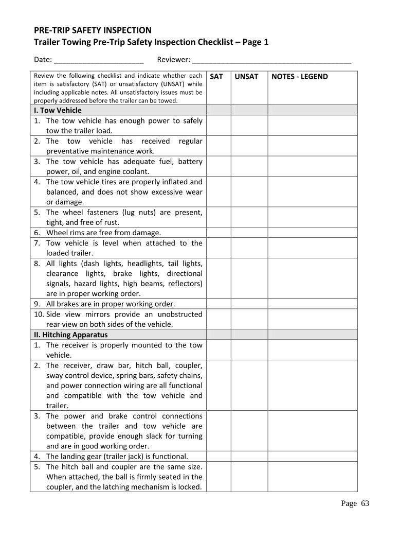
Page 63
PRE-TRIP SAFETY INSPECTION Trailer Towing Pre-Trip Safety Inspection Checklist – Page 1
Date: ______________________ Reviewer: _______________________________________
Review the following checklist and indicate whether each item is satisfactory (SAT) or unsatisfactory (UNSAT) while including applicable notes. All unsatisfactory issues must be properly addressed before the trailer can be towed.
SAT UNSAT NOTES - LEGEND
I. Tow Vehicle
1. The tow vehicle has enough power to safely tow the trailer load.
2. The tow vehicle has received regular preventative maintenance work.
3. The tow vehicle has adequate fuel, battery power, oil, and engine coolant.
4. The tow vehicle tires are properly inflated and balanced, and does not show excessive wear or damage.
5. The wheel fasteners (lug nuts) are present, tight, and free of rust.
6. Wheel rims are free from damage.
7. Tow vehicle is level when attached to the loaded trailer.
8. All lights (dash lights, headlights, tail lights, clearance lights, brake lights, directional signals, hazard lights, high beams, reflectors) are in proper working order.
9. All brakes are in proper working order.
10. Side view mirrors provide an unobstructed rear view on both sides of the vehicle.
II. Hitching Apparatus
1. The receiver is properly mounted to the tow vehicle.
2. The receiver, draw bar, hitch ball, coupler, sway control device, spring bars, safety chains, and power connection wiring are all functional and compatible with the tow vehicle and trailer.
3. The power and brake control connections between the trailer and tow vehicle are compatible, provide enough slack for turning and are in good working order.
4. The landing gear (trailer jack) is functional.
5. The hitch ball and coupler are the same size. When attached, the ball is firmly seated in the coupler, and the latching mechanism is locked.
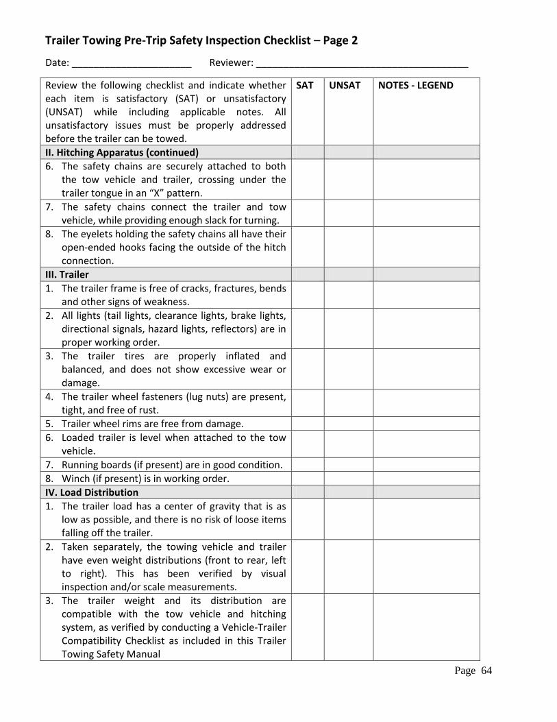
Page 64
Trailer Towing Pre-Trip Safety Inspection Checklist – Page 2
Date: ______________________ Reviewer: _______________________________________
Review the following checklist and indicate whether each item is satisfactory (SAT) or unsatisfactory (UNSAT) while including applicable notes. All unsatisfactory issues must be properly addressed before the trailer can be towed.
SAT UNSAT NOTES - LEGEND
II. Hitching Apparatus (continued)
6. The safety chains are securely attached to both the tow vehicle and trailer, crossing under the trailer tongue in an “X” pattern.
7. The safety chains connect the trailer and tow vehicle, while providing enough slack for turning.
8. The eyelets holding the safety chains all have their open-ended hooks facing the outside of the hitch connection.
III. Trailer
1. The trailer frame is free of cracks, fractures, bends and other signs of weakness.
2. All lights (tail lights, clearance lights, brake lights, directional signals, hazard lights, reflectors) are in proper working order.
3. The trailer tires are properly inflated and balanced, and does not show excessive wear or damage.
4. The trailer wheel fasteners (lug nuts) are present, tight, and free of rust.
5. Trailer wheel rims are free from damage.
6. Loaded trailer is level when attached to the tow vehicle.
7. Running boards (if present) are in good condition.
8. Winch (if present) is in working order.
IV. Load Distribution
1. The trailer load has a center of gravity that is as low as possible, and there is no risk of loose items falling off the trailer.
2. Taken separately, the towing vehicle and trailer have even weight distributions (front to rear, left to right). This has been verified by visual inspection and/or scale measurements.
3. The trailer weight and its distribution are compatible with the tow vehicle and hitching system, as verified by conducting a Vehicle-Trailer Compatibility Checklist as included in this Trailer Towing Safety Manual
Page 65
Trailer Towing Pre-Trip Safety Inspection Checklist – Page 3 Inspection Notes /Issues Found / Remedial Action Taken:
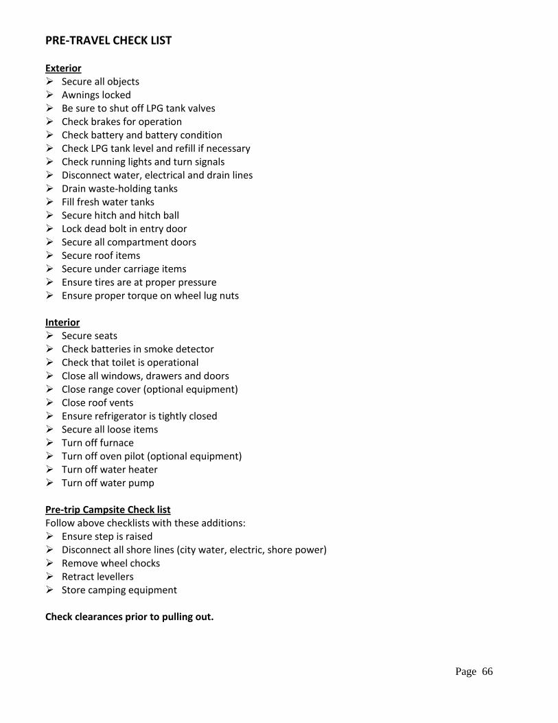
Page 66
PRE-TRAVEL CHECK LIST Exterior Secure all objects Awnings locked Be sure to shut off LPG tank valves Check brakes for operation Check battery and battery condition Check LPG tank level and refill if necessary Check running lights and turn signals Disconnect water, electrical and drain lines Drain waste-holding tanks Fill fresh water tanks Secure hitch and hitch ball Lock dead bolt in entry door Secure all compartment doors Secure roof items Secure under carriage items Ensure tires are at proper pressure Ensure proper torque on wheel lug nuts Interior Secure seats Check batteries in smoke detector Check that toilet is operational Close all windows, drawers and doors Close range cover (optional equipment) Close roof vents Ensure refrigerator is tightly closed Secure all loose items Turn off furnace Turn off oven pilot (optional equipment) Turn off water heater Turn off water pump Pre-trip Campsite Check list Follow above checklists with these additions: Ensure step is raised Disconnect all shore lines (city water, electric, shore power) Remove wheel chocks Retract levellers Store camping equipment Check clearances prior to pulling out.
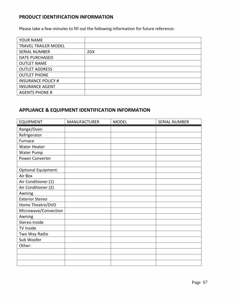
Page 67
PRODUCT IDENTIFICATION INFORMATION Please take a few minutes to fill out the following information for future reference:
YOUR NAME
TRAVEL TRAILER MODEL
SERIAL NUMBER 2GX
DATE PURCHASED
OUTLET NAME
OUTLET ADDRESS
OUTLET PHONE
INSURANCE POLICY #
INSURANCE AGENT
AGENTS PHONE #
APPLIANCE & EQUIPMENT IDENTIFICATION INFORMATION
EQUIPMENT MANUFACTURER MODEL SERIAL NUMBER
Range/Oven
Refrigerator
Furnace
Water Heater
Water Pump
Power Converter
Optional Equipment:
Air Box
Air Conditioner (1)
Air Conditioner (2)
Awning
Exterior Stereo
Home Theatre/DVD
Microwave/Convection
Awning
Stereo Inside
TV Inside
Two Way Radio
Sub Woofer
Other:


