47
RME Users Manual Models: 12E, 18E, 24E, 30E, 36E Document #500006 Rev. E March 2001
| Date post: | 30-Mar-2018 |
| Category: |
Documents |
| Upload: | hoangthuan |
| View: | 215 times |
| Download: | 1 times |

RME
Users Manual
Models: 12E, 18E, 24E, 30E, 36E
Document #500006 Rev. E March 2001


RME Users Manual Rain Master Irrigation Systems
Page i
Table of Contents
1.0 Introduction................................................................................1
2.0 RME Series Controller Features ..............................................2 2.1 Words and Terms Used in the Display ........................................4 2.2 Function Keys ..............................................................................5 2.3 Execute Keys ...............................................................................6 2.4 Data Keys.....................................................................................6
3.0 Hello Mode and Automatic Default Program .........................7 3.1 Automatic Mode ..........................................................................7 3.2 Rain Mode....................................................................................8
3.2.1 Rain Switch............................................................................8 3.2.2 Programmable Rain ...............................................................8
3.3 Battery Backup and Power Failures.............................................8 4.0 Basic Programming Examples................................................10
4.1 Fundamental Information Required in a Program .....................11 4.2 Set Time.....................................................................................11 4.3 Program......................................................................................11
4.3.1 Program Selection................................................................12 4.3.2 Program Clear......................................................................12
4.4 Watering Day Selections............................................................12 4.4.1 Water Days ..........................................................................13 4.4.2 Skip Days.............................................................................14
4.5 Stations and Watering Lengths ..................................................15 4.5.1 Stations ................................................................................15 4.5.2 Quick Stations......................................................................17
4.6 Percentage ..................................................................................17 4.7 Start Times and Automatic Program Overlap Protection ..........18
4.7.1 Start Times...........................................................................19 4.8 Program 4 Capabilities...............................................................20
5.0 Reviewing the Program ...........................................................21
6.0 Manually Activated Functions With Examples.....................22
7.0 Manual Program Execution....................................................22
8.0 Manual Station Execution.......................................................23

Rain Master Irrigation Systems RME Users Manual
Page ii
9.0 Manual Master Valve/Pump Execution.................................24
10.0 Manual System Check/Syringe Cycle ....................................24
11.0 Built-In Options .......................................................................25 11.1 Disabling the Automatic Program Overlap Protection Option..26 11.2 Activate the Access Code Option..............................................26
11.2.1 Establishing your Access Code Number .............................27 11.3 Disabling the Automatic Default Program Option ....................28
12.0 Quick Reference Quick............................................................28
13.0 Complex Example ....................................................................28 13.1 Set Time ....................................................................................29 13.2 Program 1 ..................................................................................29
13.2.1 Watering Day Selections .....................................................30 13.2.2 Stations ................................................................................30 13.2.3 Start Times...........................................................................31
13.3 Program 2 ..................................................................................31 13.3.1 Watering Day Selections .....................................................31 13.3.2 Stations ................................................................................32 13.3.3 Start Times...........................................................................32
13.4 Program 3 ..................................................................................32 13.4.1 Watering Day Selections .....................................................33 13.4.2 Stations ................................................................................33 13.4.3 Start Times...........................................................................33
14.0 Controller Placement...............................................................34 14.1 Mounting The Outdoor Controller ............................................34 14.2 Mounting The Indoor Controller ...............................................34
15.0 Electrical Connections for the Controller..............................35 15.1 Controller Connections for the Utility Power............................35 15.2 Controller Connections for Valves and Field Wiring................37 15.3 Battery Precautions and Installations ........................................37 15.4 Tapping Wires to Locate Valves in the Field ............................38 15.5 Electrical Specifications ............................................................38 15.6 Electrical Connections for a Master Valve, Pump, and
Appliances .................................................................................39 15.6.1 Electrical Connections for a Master valve...........................39 15.6.2 Electrical Connection for a Pump........................................39

Rain Master Irrigation Systems RME Users Manual
Page iii
15.6.3 Electrical Connections for an Appliance .............................39 16.0 Remote Control Capability .....................................................40
17.0 In Case of Difficulties...............................................................41 17.1 Display is Blank ........................................................................41 17.2 After Power Failure – Unable to Program or the Display is
Scrambled..................................................................................41 17.3 No Stations Turn On Automatically..........................................41 17.4 A Station Does Not Turn Off ....................................................41
Table of Figures
Figure 1 - Power and Field Wiring .........................................................36 Figure 2 - Electric Connections for a Pump and Appliances ..................40


RME Users Manual Rain Master Irrigations Systems
Page 1
A Few Very Important Notes
All holes for mounting the controller to the wall or pedestal are provided. Do not drill additional holes in the case. Metal shavings will mix with the electronics and damage will result. See Section 10 for complete mounting instructions. The controller is capable of controlling a master valve/pump; please refer to Section 11.6 for instructions. Improper installation will result in damage to the controller. Never install the NICAD rechargeable backup battery before permanent utility power is applied to the controller. For safety reasons, the battery is shipped in a unique discharged state. This will prevent the controller from turning on if it is connected before utility power. A Quick Reference Instruction Sheet written in Spanish is available for our controllers. Please contact the factory or the nearest Rain Master Irrigation Systems Authorized Distributor.
1.0 Introduction We would like to thank you for your expression of confidence in having selected a Rain Master Irrigation System’s controller. You have chosen a product of the highest quality; the controller will provide many years of trouble-free service and enhance the appearance of your landscape through the efficient control of water. Your RMIS controller contains many features which will simplify the control of your irrigation system as well as provide ease of maintenance of your system should the need arise. Although, you may certainly use our controllers as referenced in the Quick Reference sheet attached to the interior surface of the controller’s door, we suggest you take a few moments to read this manual which details all the capabilities of this unit. Should you have any questions, feel free to call Rain Master Irrigation Systems or contact your local Rain Master Authorized Distributor.

Rain Master Irrigation Systems RME Users Manual
Page 2
2.0 RME Series Controller Features 1. All solid-state design with accuracy to the second. No moving parts
to wear out.
2. Protected 24-key keyboard.
3. Multiple displays simplify programming and programming information review. The display indicates the active status of stations and irrigation programs.
4. The Review feature allows the operator to quickly obtain status and settings with a single keystroke.
5. The unit can be purchased with a combination of indoor and weatherproof outdoor enclosures.
6. A rechargeable battery prevents the loss of program information, and the current date and time in case of power failure.
7. In case of power failure and battery failure, the Automatic Default Program (ADP), will run every station 10 minutes per day, until the failure can be rectified. This feature can be disabled if desired.
8. Manual re-settable circuit breaker in case of over current, no fuse to replace.
9. The system provides an automatic Master Valve/Pump start circuit, which may also be controlled independently in the Manual mode.
10. The system provides three programs with twelve start times (four start times per program).
11. A fourth program with only one start time is available, which may be used for dripped or programmed syringe cycle irrigation.
12. The watering length for each station may be set from 1 minute to 9 hours and 59 minutes, in one-minute increments.
13. The system provides a Quick Stations feature, which allows the operator to rapidly programs a block of stations all with the same watering time lengths.
14. The Percentage key may be used for water budgeting to increase/decrease the watering length of all stations, at one time, from 0 to 300%.

RME Users Manual Rain Master Irrigations Systems
Page 3
15. Water days for each program may be based on a seven-day week or on a skip day’s routine. This allowing a program to skip from 1 to 30 days between watering cycles.
16. The system provides a programmable rain cycle feature. This feature allows the operator to select the number of days the controller will stay in the Rain Shut-down Mode. After the selected interval expires the controller automatically returns to the Automatic Mode of operation.
17. The manually activated System Check/Syringe Cycle feature will sequentially turn-on and off each station for an operator selected interval between one minute and nine minutes.
18. All stations in a program run in a sequential fashion.
19. The Rain Switch (Auto/OFF) feature turns off all stations, during rain periods, without disturbing any of the programs.
20. The unit can be configured to use input power of 120VAC, 50/60Hz or 220/240VAC, 50Hz power.
21. A freestanding pedestal enclosure is available for mounting the controller outdoors.
22. The Manual Programming feature allows the operator to manually configured and run any program.
23. The Manual Station feature allows the operator to turn on any selected station for a specified time period.
24. The Automatic Program Overlap (APOP) feature ensures that only one program runs at a time. If simultaneous program execution is desired, this will disable the Automatic Program Overlap feature.
25. A built-in Access Code feature allows the operator, if desired, to assign a password security protection to the system programs. The access code would then be required prior to entry or modification of existing programs.
26. A Remote control capability is built into every controller.
27. A Built-in Self-Test feature is available to validate the operational readiness of the entire controller.
28. The Rain Master Irrigation Systems RME Controller is UL approved.

Rain Master Irrigation Systems RME Users Manual
Page 4
2.1 Words and Terms Used in the Display CODE NUM
= Code Number -Used in the Access Code option.
HI = High -Display indicator used within the Quick Station function.
I = Inhibited -Display indicator used with the Rain Switch.
LFT = Left -Display indicator used within the Skip Days function.
LN = Length -Display indicator used in both Stations and Quick Stations function.
LO = Low -Display indicator used within the Quick Station function.
NO = No -Used during input to indicate invalid information entry.
OFF = OFF -Used to indicate the controller programs are inhibited.
OK = OK -Display indicator used within the Access Code option.
P OR S = Program OR Station -Display indicator used within the Manual function.
PROG = Program -Display indicator used within the Program function.
PT = Percentage -Display indicator used within the Percent function.
SD = Skip Days -Display indicator used within the Skip Days function.
SET TIME = Set Time -Display indicator used within the Set Time function.
SORRY = Sorry -Display indicator used within the Access Code option.

RME Users Manual Rain Master Irrigations Systems
Page 5
STATION = Station -Display indicator used in the Station function.
STATIONS = Stations -Display indicator used in the Review program feature.
WDAY = Water Days -Display indicator used in the Water Days function.
2.2 Function Keys
Allows selection of program 1, 2, 3, or 4.
This key is used to select the various stations and theirassociated watering lengths.
This key is used to rapidly program a block of stationswith the same watering length.
This key is used establish the watering days based on aseven-day week.
This key is used to establish the number of skipped daysbetween water cycles. Select between 1-30 days and thenselect the first day of the current week to begin watering.
This key is used to establish the start times of a program.
This key is used to set the time-of-day and the day-of-week.
This key is used to advance to the next station in aprogram when the program is already watering.
This key provides a method of water budgeting. It allowsthe operator to incremental increase or decrease, thewatering time lengths of ALL stations in a program by aset percentage factor.
PROGRAM
QUICK STATIONS
STATIONS
WATER DAYS
SKIP DAYS
START TIMES
SET TIME
MANUAL
PERCENT

Rain Master Irrigation Systems RME Users Manual
Page 6
2.3 Execute Keys This key will store the previously entered the information
into the controller.
Used for clearing stations, programs, water days, etc.
Quits the enter action and returns the operator to the Automatic mode.
2.4 Data Keys These keys are used to enter values, select days of the week, or time of day, with using the controller.
SUN
1
SAT
7
MON
2 WED
4 THU
5
TUE
3 FRI
6
AM
PM
8
9
0
ENTER
QUIT
CLEAR

RME Users Manual Rain Master Irrigations Systems
Page 7
3.0 Hello Mode and Automatic Default Program When the controller is first powered up, HELLO will be displayed. In HELLO Mode the Automatic Default Program (ADP) will run every station, every day for 10 minutes. Should you have a power failure and the back-up battery is faulty, which maintains key parameters of the controller, the ADP program ensures that your landscape will be watered when power returns. To disable the Automatic Default Program refer to section 7.3. In HELLO mode, the ADP will begin the first watering cycle six hours after power is reapplied and then continue at twenty-four hour intervals until the controller is reprogrammed. Pressing any key will automatically clears the HELLO Mode and ADP.
3.1 Automatic Mode The controller is in the Automatic Mode whenever time is displayed and the day-of-the-week indicator is lit. To return to the Automatic Mode of operation, Press: When a program is watering in the Automatic Mode, the station number(s) and program number(s) will be displayed. To advance to the next station in a program when a program is already watering, Press: To stop and cancel a program that is watering, Press: The controller will return to the Automatic Mode.
QUIT
MANUAL
QUIT CLEAR

Rain Master Irrigation Systems RME Users Manual
Page 8
3.2 Rain Mode There are two ways to place the controller in the Rain Mode.
3.2.1 Rain Switch The controller is equipped with a rain shutoff switch. The switch MUST BE in the AUTO position anytime a watering cycle is desired. In the AUTO position, watering WILL occur if the controller is programmed to do so. The switch should be placed in the OFF position when no watering is desired, such as when it is raining or windy. In the rain switch OFF position no watering will occur and the letter “I” will appear in the display to indicate that all programs are inhibited from watering. The user’s programs will remain intact and upon returning the rain switch to the ON position normal program watering will occur.
3.2.2 Programmable Rain The controller is capable of being turned off from 1 to 7 days for rain, wind, or scheduled maintenance. This method is used in place of the Rain Shutdown Switch when you know how many days you want the controller to stay off, the controller will stay in the Rain shutdown mode for the days selected after which it will go back to the Automatic program mode of operation. Example: You wish the controller to stay off for 6 days. Press: The controller will display RAIN 6. At midnight of each day the controller will decrement by one day until it reaches zero at which point it automatically returns to program mode. Note: no watering will occur when the controller returns to the Automatic Mode if the Rain Switch is in the OFF position.
3.3 Battery Backup and Power Failures The controller uses a rechargeable battery to keep the program information and time intact during power failures. When power goes out, the display of the controller will go blank to conserve battery power and
FRI
6 ENTER CLEAR

RME Users Manual Rain Master Irrigations Systems
Page 9
when it returns, the display will light up and show the correct time and day. Note: no watering will occur during power outages. If HELLO appears on the display, the power outage outlasted the battery backup and all program information was lost. The controller will run the ADP, as described in Section 3.0, until you reprogram it. When power has been restored, the controller will automatically recharge the battery. Upon return of power, should there appear anything other than HELLO or the time and day appear in the display, the unit has faulted and must be properly reset. To reset the controller disconnect the battery, press the RESET button for approximately 30 seconds, reprogram the controller and reconnect the battery.

Rain Master Irrigation Systems RME Users Manual
Page 10
4.0 Basic Programming Examples The following table is a representation of what information may be programmed by you to control the irrigation system using the Automatic Program Mode. The controller does not need to be programmed in any particular order.
Table 1- Available Program Options Program 1 Program 2 Program 3 Program 4
χ χ
Start Time 1 Start Time 2 Start Time 3 Start Time 4
χ χ
χ χ
Start Time 1 Start Time 2 Start Time 3 Start Time 4
χ χ
χ χ
Start Time 1 Start Time 2 Start Time 3 Start Time 4
χ χ
χ χ
Start Time 1 χ χ χ χ χ
Water Days Or Skip Days
χ χ
Water Days Or Skip Days
χ χ
Water Days Or Skip Days
χ χ
Water Days χ χ χ
Percentage Default=100%
χ χ
Percentage Default=100%
χ χ
Percentage Default=100%
χ χ
Percentage Fixed at 100%
χ χ
The following sections will describe how to program the controller, as well as how to review and clear program information.
Station1 with its one watering time length may be in Programs 1 and/or 2, and/or 3 but it will always have the same watering length. Station 2 – the same. Station 36 – the same
Any stations, if used in other programs, may also be used here. However, all of these stations will have the same watering length.
RME Users Manual Rain Master Irrigations Systems
Page 11
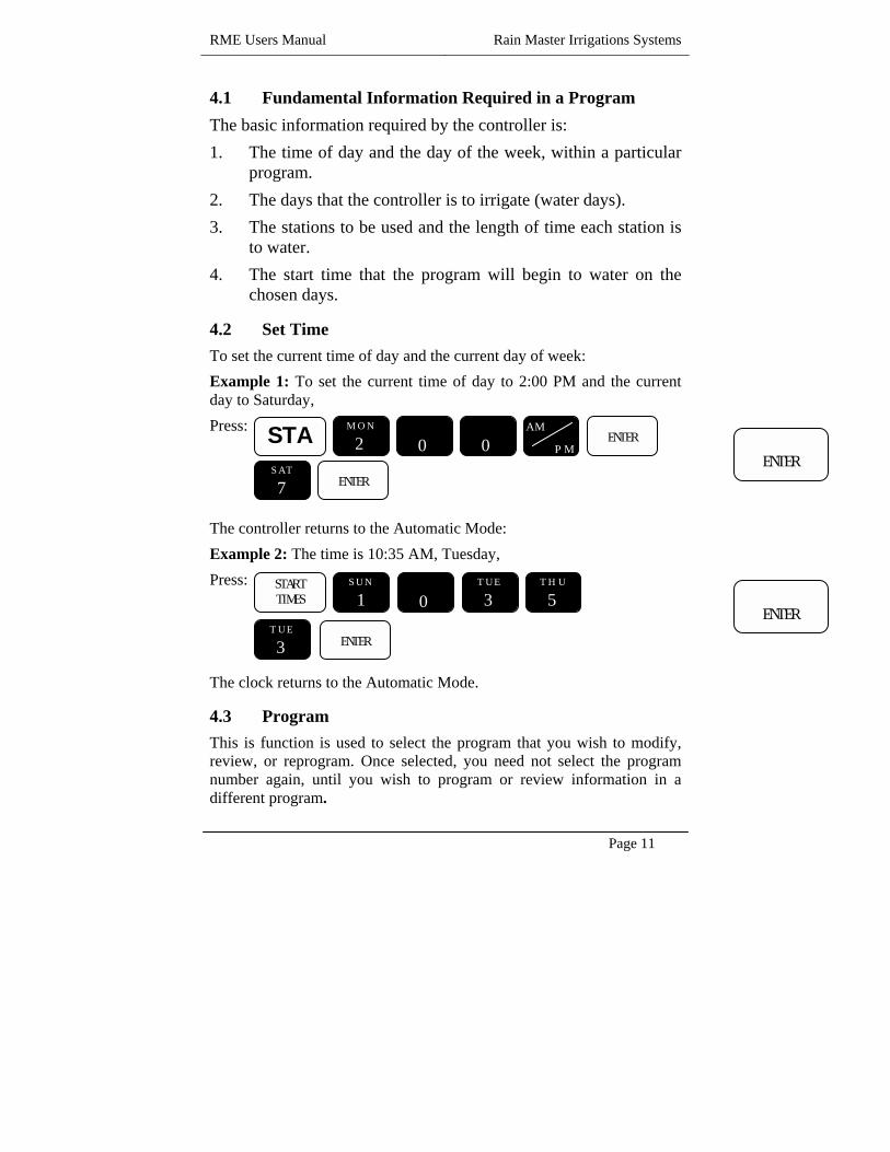
4.1 Fundamental Information Required in a Program The basic information required by the controller is: 1. The time of day and the day of the week, within a particular
program. 2. The days that the controller is to irrigate (water days). 3. The stations to be used and the length of time each station is
to water. 4. The start time that the program will begin to water on the
chosen days.
4.2 Set Time To set the current time of day and the current day of week: Example 1: To set the current time of day to 2:00 PM and the current day to Saturday, Press: The controller returns to the Automatic Mode: Example 2: The time is 10:35 AM, Tuesday, Press: The clock returns to the Automatic Mode.
4.3 Program This is function is used to select the program that you wish to modify, review, or reprogram. Once selected, you need not select the program number again, until you wish to program or review information in a different program.
ENTER
ENTER
MON
2 AM
PM
0 STA ENTER
0 SAT
7 ENTER
SUN
1 THU
5 TUE
3
0 START TIMES
TUE
3 ENTER

Rain Master Irrigation Systems RME Users Manual
Page 12
There are four (4) user selectable programs available. They are referred to as programs 1, 2, 3 and 4. The fourth program has limited capabilities, which are described in Section 4.8. The program function is used to select, as will as clear the parameters of a user program. If desired, it is also possible to both select and clear ALL information in a program using this function.
4.3.1 Program Selection The operator uses the program selection function to select one of the four controller programs, for reprogramming or modification. While programming the various functions, the selected program number is continuously displayed for the operator’s convenience. Example: The operator wants to modify Program 2, Press: The controller returns to the Automatic Mode.
4.3.2 Program Clear The operator uses the program selection function to select one of the four controller programs, to be cleared. Example: The operator wants to clear all information in Program 1, Press: The controller returns to the Automatic Mode.
4.4 Watering Day Selections Watering day selection for Programs 1, 2 and 3 may be set based on a seven (7) day week or based on a skip days mode. The controller is not capable of doing both within the same selected program. Each program may be set to one or the other watering day modes of operation. As an example, Program 1 may be programmed to a seven (7) day weekly basis and Program 2 can be programmed based on a skip day basis. Program 4 can only be programmed to use the seven (7) day weekly mode.
PROGRAM
SUN
1
MON
2 ENTER
CLEAR PROGRAM

RME Users Manual Rain Master Irrigations Systems
Page 13
4.4.1 Water Days This function is used to select the watering days based on a seven (7) day week. Watering will occur on the days programmed each week. The selected watering days are shown in the top display. The associated program number is shown in the display as an operator convenience. Example: The water days are to be Sunday, Wednesday, and Friday. Press: The controller returns to the Automatic Mode. Example: To clear a watering day, such as Sunday. Press: If done, Press: The controller returns to the Automatic Mode. Example: To review Water Day information Press: When done, Press: The controller returns to the Automatic Mode.
SUN
1 WED
4 FRI
6
WATER DAYS ENTER
QUIT
ENTER
ENTER
SUN
1 WATER DAYS CLEAR
QUIT
QUIT
WATER DAYS

Rain Master Irrigation Systems RME Users Manual
Page 14
4.4.2 Skip Days This function is used to program the number of days to be skipped between irrigation cycles. The function allows the operator to select between one (1) to thirty (30) days until the first watering cycle will begin. By using the skip days mode you can have a program water every 2nd, 3rd 4th, …… or 30th day as may be required. If previous information had been entered, the number of days to be skipped between watering cycles will be displayed. The program number that the skip day count applies to, will also be displayed. Note: if the display indicates 0 days left, this means that the watering day is today. Example: You want the program to start watering four (4) days from now. The program will water, then skip two (2) days, then water again, Press:
The controller returns to the Automatic Mode. Example: To clear all Skip Days information, Press: The controller returns to the Automatic Mode. Example: To review Skip Days information, Press: Displayed: the number of days to skip is displayed. Press: Displayed: the number of days left before the next watering day is displayed.
MON
2 WED
4
SKIP DAYS ENTER
ENTER
SKIP DAYS
ENTER
QUIT CLEAR
SKIP DAYS

RME Users Manual Rain Master Irrigations Systems
Page 15
When complete, Press: The controller returns to the Automatic Mode.
4.5 Stations and Watering Lengths The operator can program any available station to be utilized by any program. Stations may be placed in more than one program at a time if desired but a station will still have only one watering length associated with it (except if a station is utilized in Program four (4), see Section 4.8). The length of the watering cycle will be the length of time that was last programmed for that station. The watering length for each station can be programmed from 1 minute to 9 hours and 59 minutes. The smallest increment of time is one minute. There are two ways of programming a given station and it watering length into one of the programs, these methods are described in the following paragraphs.
4.5.1 Stations The first method would be to select the individual station and set the desired length of watering. After selecting the desired station number, the operator enters the watering length for the station. The percentage value associated with this station is briefly displayed at the beginning of the entry to remind you of its setting. Selected stations are displayed in the top display. The program number is displayed for the convenience of the operator. Example: The operator wants to set Station 1 for a watering length of 10 minutes, Station2 for 10 minutes, Station 6 for 1 hour and 15 minutes, and station 7 for 8 minutes. Press: The controller returns to the Automatic Mode.
QUIT
SUN
1 STATIONS ENTER

Rain Master Irrigation Systems RME Users Manual
Page 16
Example: To clear station 7 and it’s associated watering length: Press: When complete, Press: The controller returns to the Automatic Mode. Example: To review Station number 6 information: Press: When complete, Press: The controller returns to the Automatic Mode. Example: To review the watering length of a station 6: Press: The watering length is displayed. Press: To leave the watering length as is, Press: Example: To clear station 6 and it’s associated watering length, Press: The controller returns to the Automatic Mode.
SAT
7
QUIT
CLEAR STATIONS
QUIT
STATIONS
STATIONS FRI
6 ENTER
QUIT
CLEAR
ENTER

RME Users Manual Rain Master Irrigations Systems
Page 17
4.5.2 Quick Stations This function is used to rapidly program a block of stations. All stations will contain the same watering length. To program a block of stations, the lowest station number is entered, then the highest station number and then the watering length. The selected stations are displayed in the top display. The program number is displayed as a convenience for the operator. Example: Set station 12 through station 34 for 56 minutes, Press: The controller returns to the Automatic Mode.
4.6 Percentage The percentage function is utilized for simple water budgeting, by providing an easy method of increasing/decreasing the watering lengths of all stations in a program with one simple entry. This function is particularly useful during abnormally dry/hot or cold/wet periods of the year. The percentage is automatically set to 100 percent in all four programs by default, each station in a program will run for 100% of its programmed time. Percentage change function can be set from 0 to 300%, in increments of 1%. This applies to programs 1, 2 and 3 independently. This function is not available in Program 4; this is described in Section 4.8. Setting the percentage in a program to 161% will make the watering length of each station 1.61 times its programmed watering length. Setting the percentage to 70% will make the watering length 0.70 times its programmed watering length. Note: Even if the percentage is set to some value other than 100%, the watering length displayed for all stations in a program will not change. However, the watering length will be automatically modified when the station waters.
SUN
1 MON
2 WED
4 THU
5
TUE
3 FRI
6
QUICK STATIONS ENTER
ENTER
ENTER

Rain Master Irrigation Systems RME Users Manual
Page 18
Example: The operator sets a program percentage of 110%, which will increase the watering lengths of all stations in a program by 10%. Press: The controller returns to the Automatic Mode. Example: To clear Percentage Press: The Percentage is reset to 100 and the controller returns to the Automatic Mode. Example: To review Percentage value. Press: When done Press: The controller returns to the Automatic Mode.
4.7 Start Times and Automatic Program Overlap Protection Programs 1 – 3 can have as many as four start times, they are referred to as Start Time 1 through Start Time 4. Program 4 has only one start time available and is referred to as Start Time 1. The controller features Automatic Program Overlap Protection (APOP). This ensures that if start times cause scheduled programs to overlap, only one program will run at a time. Anytime a program is watering and the start time for another program is ready to start, the conflicting program will be delayed until the current program completes its watering cycle. Example: Program 1 has time duration of one hour based on the stations used and the watering lengths. The operator sets three start times all to 7:00 AM. The program will water three times, from 7:00AM to 8:00AM, 8:00AM to 9:00AM, and 9:00AM to 10:00AM, providing two repeat cycles.
SUN
1
0 PERCENT ENTER
SUN
1
PERCENT QUIT CLEAR
PERCENT
QUIT
RME Users Manual Rain Master Irrigations Systems
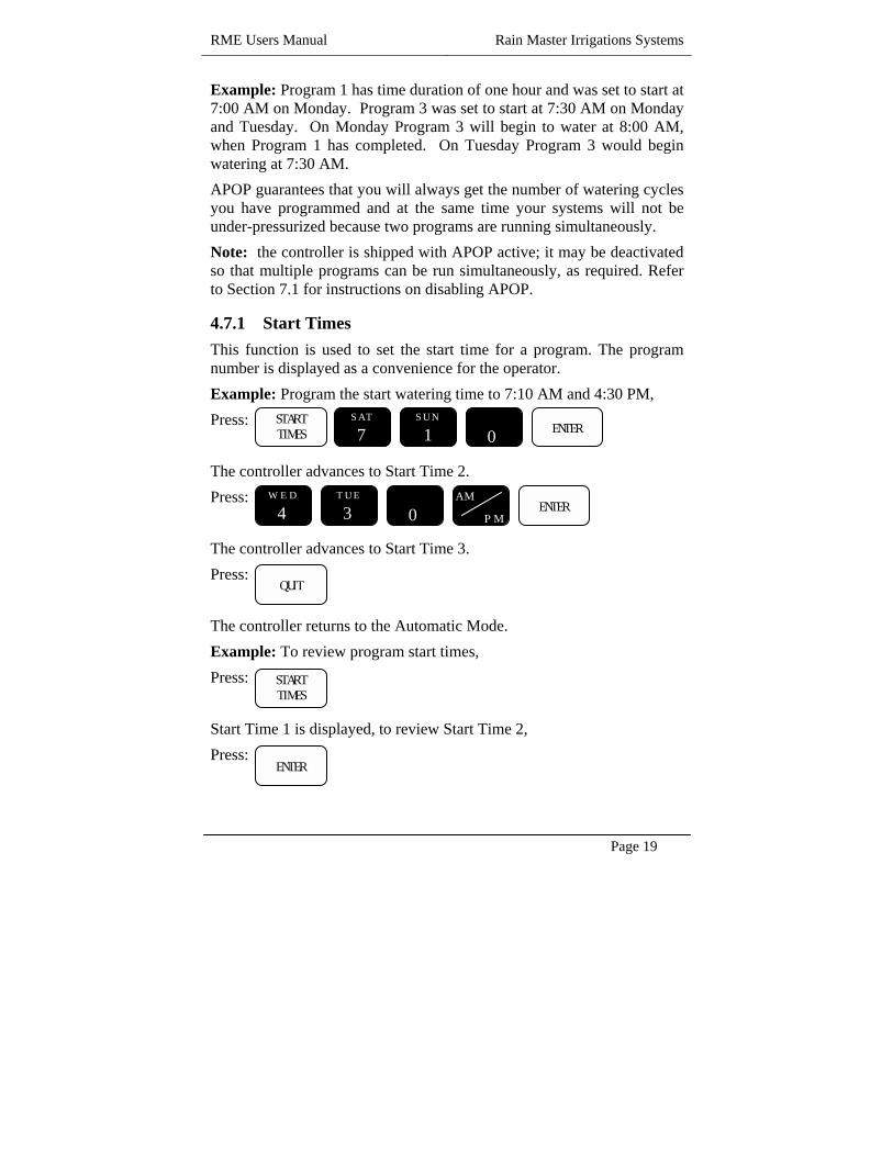
Page 19
Example: Program 1 has time duration of one hour and was set to start at 7:00 AM on Monday. Program 3 was set to start at 7:30 AM on Monday and Tuesday. On Monday Program 3 will begin to water at 8:00 AM, when Program 1 has completed. On Tuesday Program 3 would begin watering at 7:30 AM. APOP guarantees that you will always get the number of watering cycles you have programmed and at the same time your systems will not be under-pressurized because two programs are running simultaneously. Note: the controller is shipped with APOP active; it may be deactivated so that multiple programs can be run simultaneously, as required. Refer to Section 7.1 for instructions on disabling APOP.
4.7.1 Start Times This function is used to set the start time for a program. The program number is displayed as a convenience for the operator. Example: Program the start watering time to 7:10 AM and 4:30 PM, Press: The controller advances to Start Time 2. Press: The controller advances to Start Time 3. Press: The controller returns to the Automatic Mode. Example: To review program start times, Press: Start Time 1 is displayed, to review Start Time 2, Press:
SUN
1 SAT
7
WED
4 TUE
3 AM
PM
0 START TIMES ENTER
0 ENTER
START TIMES
QUIT
ENTER

Rain Master Irrigation Systems RME Users Manual
Page 20
When done, Press: The controller returns to the Automatic Mode. Example: To clear Start Time 2, Press: Start Time 1 is displayed, to advance to Start Time 2, Press: Start Time 2 is displayed. To clear it, Press: The controller returns to the Automatic Mode.
4.8 Program 4 Capabilities The purpose of Program 4 is to accommodate a programmed syringe cycle or drip irrigation systems. This program functions the same as the first three programs with the following exceptions:
1. Program 4 only has one Start Time. 2. The Water Days function can be used. The Skip Water Days
function is not available. 3. There is only one watering length associated with all stations
utilized in Program four (4). Example: program Station 5 for 10 minutes and then program Station 2 for 11 minutes, all stations in Program 4 will have a watering length of 11 minutes each. This is based on the watering length associated with the station last programmed.
QUIT
START TIMES
QUIT
ENTER
CLEAR

RME Users Manual Rain Master Irrigations Systems
Page 21
Stations also assigned to other programs may also be placed in Program four (4). The watering length associated with stations in Program 4 will not effect the watering lengths assigned to stations have in other programs.
4. Water budget percentage can’t be used in Program four (4); it is fixed at 100%.
5.0 Reviewing the Program A unique feature of the controller is its review function capability. Push the review button and all program information will be displayed at a sequential rate. Information in Program 1 will be displayed first, followed in sequential fashion by: Start Times1, 2, 3 and 4 (displayed as Start Times), Water Days (displayed as WDAY), Skip Days (displayed as SD), followed by the number of days left till the next watering (displayed as LFT), Percentage (displayed as PT), Stations and their watering lengths (displayed as STATIONS), The total watering time for the program (displayed with an H and M to indicate hours and minutes) (Refer to section Words and Terms Used in the Display.) Then the information for Programs 2, 3 and 4 will be displayed. It is important to note that the watering length shown for each station is the programmed length. It does not represent the actual watering length if the operator has utilized the percentage function to increase or decrease the overall watering length. Note: at any time during the Review cycle you may abort the review cycle by, Pressing: The controller returns to the Automatic Mode. If any other key is pressed, the Review cycle will abort and the controller will perform the function selected.
QUIT

Rain Master Irrigation Systems RME Users Manual
Page 22
6.0 Manually Activated Functions With Examples The Manual Mode provides four functions. Each function is described in the following paragraphs.
7.0 Manual Program Execution The following example can be used to manually execute a previous programmed set-up. Example: To run Program number one (1), Press: The controller returns to the Automatic Mode. Number 1 is displayed to indicate Program 1 is running. All active programmed stations are also displayed. Example: To advance to the next station when the Program is already watering, Press: Example: To cancel the watering program, Press: The controller returns to the Automatic Mode.
PROGRAM SUN
1 MANUAL ENTER
QUIT CLEAR
MANUAL

RME Users Manual Rain Master Irrigations Systems
Page 23
8.0 Manual Station Execution This is mode is used to run a selected station for a specified time. Example: Manually water Station 6 for 25 minutes, Press: The display will indicate the station that is running and the associated watering time. As time elapses, the watering time will display the watering time remaining. At completion of the watering time, the station will shut off and the controller will return to the Automatic Mode. Example: To cancel the manually station watering mode, Press: The controller will return to the Automatic Mode.
MON
2 THU
5
FRI
6 MANUAL ENTER
QUIT CLEAR
STATIONS
ENTER

Rain Master Irrigation Systems RME Users Manual
Page 24
9.0 Manual Master Valve/Pump Execution The Manual Master Valve/Pump function allows manual on/off control of the Master valve and/or Pump for a specified time. Master Valve/Pump is always specified as one station greater than the total number of station terminals available in the controller. As an example the Master Valve/Pump would be station number thirteen (13) in a twelve station (12) controller. Example: Manually turn on the Master Valve, for 22 minutes, Press: Example: To cancel the manual control of the Master Valve, Press: The controller will return to the Automatic Mode.
10.0 Manual System Check/Syringe Cycle For convenience in troubleshooting system problems or for quick water cycle control, the controller has a system check feature built in. This will run each station, in the configuration, for a selectable time of one (1) to nine (9) minutes. Example: To run a system check for 3 minutes, Press: Do not press CHECK will be displayed to indicate that the controller is in the Check Mode. When the last station has watered, the controller will return to the Automatic Mode.
SUN
1
MON
2
TUE
3 STATIONS MANUAL ENTER
QUIT CLEAR
MON
2 ENTER
MON
2 MANUAL
ENTER

RME Users Manual Rain Master Irrigations Systems
Page 25
Example: To advance to the next station, one station at a time, Press: Example: To cancel the System Check mode, Press: The controller returns to the Automatic Mode.
CAUTION This mode sequentially runs every station in the controller configuration. For example, if you have a 24-station unit but only use 23 stations connected, it will apply power to Station 24 and doing so will activate the Master Valve/Pump terminal. If the system utilizes a pump, during the time that Station 24 is activate, the pump will be pumping water against a closed system. If the system utilizes a master valve, it will be activated during the time that Station 24 is activate and this could cause excess heating of the master valve’s solenoid if the valve depends on the water flow to cool it. If all stations in the configuration are not used, cancel the system Check/Syringe cycle after the last station, which is used, has completed watering.
11.0 Built-In Options The controller contains three built-in options which may be use should your irrigation application call for it. The options are delimited in the following paragraphs. Activating any of these options requires the removal of power from the unit, both utility and battery power, must be removed from the controller. This will cause all users’ programs to be lost. To activate any of the options, proceed as follows: (Note that once an option is activated, it can only be deactivated at the factory or at an RMIS Authorized Repair Center.)
1. Remove the lower plate of the controller. 2. Disconnect both the battery and the utility power.
MANUAL
QUIT CLEAR

Rain Master Irrigation Systems RME Users Manual
Page 26
Note: This will cause all users’ programs to be lost. 3. On the printed circuit board just above the transformer are
jumper wires which activate the following options: a. Locate option wire “O”. Removal of this wire will
disable the Automatic Program Overlap Protection. b. Locate option wire “A”. Removal of this wire will
activate the Access Code option. c. Locate option wire “D”. Removal of this wire will
deactivate the Automatic Default Program option. 4. Carefully cut the jumper wire and discard it. Use a sharp wire
cutter and do not press hard into the circuit board with the cutters.
5. Reconnect utility power and reprogram the controller. 6. Reconnect the battery and replace the lower plate.
11.1 Disabling the Automatic Program Overlap Protection Option
The Automatic Program Overlap Protection option (APOP) is explained in Section 4.7. This option insures that only one program will run at a time. The controller is shipped with APOP active, it may be deactivated, using the procedure outlined above, allowing programs to run whenever they are set to do so. This may be advantageous when your water supply is sufficient to run programs simultaneously and you have a short time in which to water. If you run programs simultaneously, you must consider the wattage being drawn by each valve solenoid to ensure that excessive power is not drawn from the transformer. See Section 11.5.
11.2 Activate the Access Code Option The Access Code option allows the user to establish an access code number, which must be entered anything a program is changed or modified. It is used to prevent unauthorized people from changing the users program. The code can be any number between the number 0 to 9999 and must be entered into the controller prior to any fundamental program information can be changed.

RME Users Manual Rain Master Irrigations Systems
Page 27
The controller is shipped with the options deactivated so that all functions are available to the user. If the Access Code option is activated, as outlined above, only the following controller functions are available without entering the access code number.
1. Setting the controller date and time. 2. Review of program information. 3. All Manual Mode functions can be used. 4. The Programmable Rain function. 5. The Rain Switch. All other functions will require the entry of the access code number, before they may be used. If the user attempts to access these controlled functions, by pressing a key, the word SORRY will appear in the display momentarily and the controller will return to the Automatic Mode. To activate the Access Code option, follow the steps in Section 7.0.
11.2.1 Establishing your Access Code Number Once the controller hardware is configured for the Access Code option, an Access Code number must be established prior to programming the unit. To establish your Access Code number, proceed as follows: Example: Access code number will be 34, Press: The controller displays “OK” and returns to the Automatic Mode. You may now program all functions of the controller. To set the controller to the No Access Mode after programming, perform one of the following procedures: Simply leave the controller in the Automatic Mode of operation. At midnight the controller will notice that an Access Code was entered earlier and it will go to the No Access Mode automatically. To place the controller in the No Access Mode immediately after completing all programming, attempt to enter a code number other than
WED
4 TUE
3
MANUAL ENTER
ENTER

Rain Master Irrigation Systems RME Users Manual
Page 28
the code number you established earlier. Once the controller is in the No Access Mode, you must enter the correct # to program the controller. To do so, simply proceed as you did to establish your code # but you must use the correct code (in this example, 34) or access will be denied. Once an Access Code number has been established, the code number can’t be changed unless both battery and utility power are removed for 30 seconds. Reapply power and establishing a code number as per the example above. NOTE: removal of power will cause all programs to be lost. Note that if a power failure should occur and if it outlasts the battery backup, the controller will go into the HELLO mode when power is returned and an Access Code number must be established prior to programming the controller.
11.3 Disabling the Automatic Default Program Option The Automatic Default Program (ADP) is explained in Section 3.0. The ADP mode insures that each station will run for ten (10) minutes per day, in the event there is no user’s program. The controller is shipped with the ADP activated, however, it may be deactivated. If this is done, no watering will occur when the controller says “HELLO”. This may be advantageous for systems using pumps; see the CAUTION’S outlined in section 6.4. To deactivate ADP, follow the steps in Section 7.0.
12.0 Quick Reference Quick A copy of the Quick Reference Guide is attached to the inside face on the front door of the controller. This guide provides simple examples of various programming techniques.
13.0 Complex Example The following complex example demonstrates how to fully utilize the controller. The controller requirements are a follows: Your house has a large area of grass, a flower garden and rows of trees along the sides and back of the property. A total of seven (7) stations will be required to control the irrigation of your landscape and you have a 12-station controller. You wish to program the water cycles as follows:

RME Users Manual Rain Master Irrigations Systems
Page 29
Program 1: The lawn area is to be watered every 3rd day starting tomorrow.
Station 1 and 2 will water for 10 minutes. Station 6 will water for 15 minutes. Station 7 will water for 8 minutes. The program start time will be 6:00 AM.
Program 2: The flower garden is to be watered every day except Sunday.
Station 4 and 5 will water for 6 minutes. The program start time will be 7:00 AM and 1:00 PM.
Program 3: The trees will be watered today and then every 19 days thereafter.
Station 3 will water for 9 hours. The program start time will be 3:00 PM.
13.1 Set Time Example: Set the time of day and the day of the week. The time is 2:00 PM, Saturday. Press: The controller returns to the Automatic Mode.
13.2 Program 1 You want to place program information in Program 1. However, it already has information in it, which must be overwritten. Example: To select then clear the entire contents of Program 1, Press: The controller returns to the Automatic mode.
ENTER
MON
2 AM
PM
0 SET
TIME
ENTER
0 SAT
7
PROGRAM SUN
1 CLEAR

Rain Master Irrigation Systems RME Users Manual
Page 30
13.2.1 Watering Day Selections Example: Set the watering days for Program 1 to skip 2 days, for every third day of watering and tomorrow will water the watering cycle, Press: The controller returns to the Automatic Mode.
13.2.2 Stations Example: Select the stations to be used by Program 1 and the station’s associated watering lengths. Set station 1 for 10 minutes, Station 2 for 10 minutes, Station 6 for 15 minutes and Station 7 for 8 minutes. Press: Press: The controller returns to the Automatic Mode.
SUN
1
MON
2 SKIP DAYS ENTER
ENTER
SUN
1
SAT
7
MON
2
THU
5
FRI
6
8
0
STATIONS ENTER
SUN
1 ENTER
ENTER
SUN
1
0 ENTER
ENTER
SUN
1 ENTER
ENTER
ENTER
QUIT

RME Users Manual Rain Master Irrigations Systems
Page 31
13.2.3 Start Times Example: Set the start time for Program 1 to 6:00 AM. Press: The controller goes back to Start Time 2. Press: The controller returns to the Automatic Mode.
13.3 Program 2 Example: Select Program 2. Press: The controller returns to the Automatic Mode.
13.3.1 Watering Day Selections Example: Select the watering days for Program 2. Press: Press:
FRI
6
0 START TIMES ENTER
QUIT
0
PROGRAM MON
2 ENTER
SAT
7
MON
2
WED
4 THU
5
TUE
3
FRI
6
WATER DAYS ENTER
QUIT
ENTER
ENTER
ENTER
ENTER
ENTER

Rain Master Irrigation Systems RME Users Manual
Page 32
The controller returns to the Automatic Mode.
13.3.2 Stations Example: Select the stations and the associated watering lengths for Program 2. Press: Press: The controller returns to the Automatic Mode.
13.3.3 Start Times Example: Set the start times for Program 2. Press: The controller advances to Start Time 2. Press: The controller advances to Start Time 3. Press: The controller returns to the Automatic Mode.
13.4 Program 3 Example: Select Program 3.
WED
4
THU
5
FRI
6
STATIONS ENTER
QUIT
FRI
6
ENTER
ENTER
ENTER
SUN
1
SAT
7
AM
PM
0 START TIMES ENTER
QUIT
0
0
0 ENTER
RME Users Manual Rain Master Irrigations Systems
Page 33
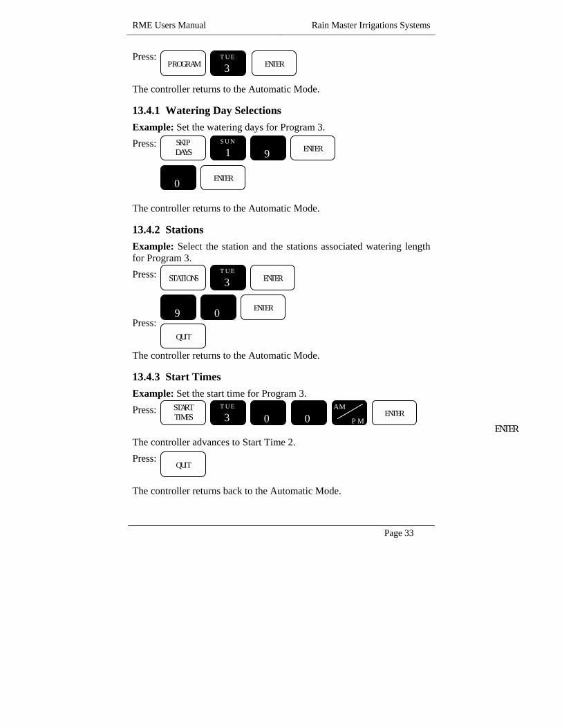
Press: The controller returns to the Automatic Mode.
13.4.1 Watering Day Selections Example: Set the watering days for Program 3. Press: The controller returns to the Automatic Mode.
13.4.2 Stations Example: Select the station and the stations associated watering length for Program 3. Press: Press: The controller returns to the Automatic Mode.
13.4.3 Start Times Example: Set the start time for Program 3. Press: The controller advances to Start Time 2. Press: The controller returns back to the Automatic Mode.
ENTER
PROGRAM TUE
3 ENTER
SUN
1
9
0
SKIP DAYS ENTER
ENTER
TUE
3
9
0
STATIONS ENTER
QUIT
ENTER
TUE
3 AM
PM
0 START TIMES ENTER
QUIT
0

Rain Master Irrigation Systems RME Users Manual
Page 34
14.0 Controller Placement WARNING Do not drill holes in the controller’s case. The case has all the holes necessary for mounting it on a wall or pedestal. Drilling holes in the unit will cause metal chips to mix with the electronics and this may cause the unit to malfunction. If, for some reason, it is absolutely necessary to drill additional holes in the unit, carefully remove all the electronics prior to doing so. Controllers are available in either an indoor or outdoor enclosure. Both are lockable and dust-free, however, the outdoor controller is also watertight. Do not place an indoor controller outdoors. Outdoor controllers should be placed in a shaded and dry environment not subject to direct sprinkler spray or continuous heavy moisture. Additionally, a pedestal is available for outdoor controllers; contact your RMIS distributor.
14.1 Mounting The Outdoor Controller 1. On an upright, flat and secure surface, place the mounting bracket
at eye level and fasten securely. 2. Mate the bracket on the back of the controller to the mounted
bracket and hang the controller. 3. Secure the bottom of the controller by placing a screw through the
hole located in its back wall at bottom center.
14.2 Mounting The Indoor Controller 1. On an upright, flat and secure surface place two screws at eye
level, 8” apart. Screw the screws into the wall leaving a 1/8” gap between the wall and the head of the screw.
2. Hang the controller on the two screws and remove its lower front plate.
3. Secure the bottom of the controller by placing a screw through the hole located in its back close to the bottom. Note: this hole is located 7 1/16” below the top two and in the center.

RME Users Manual Rain Master Irrigations Systems
Page 35
15.0 Electrical Connections for the Controller Electrical connection specifications for the controller are explained in the following paragraphs. Please read and follow these instructions carefully.
15.1 Controller Connections for the Utility Power 1. The power and field-wiring diagram is shown in figure 1. 2. Mount controller. 3. Place RAIN SWITCH to OFF position. 4. Remove lower panel. 5. Using #12 gauge or heavier copper wire, connect the ground screw
to grounding rod or grounded water pipe using a ground rod clamp. The wire should be as short as possible with no sharp bends or kinks. If multiple controllers are being installed in the same location, use a ground rod for each installation. Rain Master can provide a pamphlet on proper grounding techniques, please contact the factory.
6. Thread condulet into controller chassis. 7. Connect supply line grounded conduit to condulet. 8. Connect 120 volt AC, 50/60Hz supply line to the transformer wires
within the condulet. 9. Check and follow all appropriate local electrical wiring codes. 10. Install backup battery, as described in Section 11.3, and place it on
the bottom of the controller in the corner opposite the transformer. 11. Upon completion of all field wiring, replace the lower panel and
place the RAIN SWITCH in the AUTO position.

Rain Master Irrigation Systems RME Users Manual
Page 36
Controller Quick Disconnect
Figure 1 - Power and Field Wiring
WARNING 1. All electrical connections must be performed as described above
and the box must be properly grounded, to avoid warranty problems.
2. Disconnect power prior to making any electrical connections or doing any controller servicing.
3. For a complete reset of the controller, remove the backup battery and press RESET for 30 seconds.
4. Never short a station terminal or wire to the common terminal or common wire to create sparks for station identification.
5. While a station’s terminal is activated do not disconnect the station’s wire or the common wire.
Transformer
Valves and Field Wiring
Ground Rod or Grounded Water Pipe
Case Ground Screw
#10 Copper Wire
24 VAC COM MV 1 2 3

RME Users Manual Rain Master Irrigations Systems
Page 37
15.2 Controller Connections for Valves and Field Wiring The controller utilizes quick disconnects and color coded wires. The wires are 24inches long. Each end must be stripped and attached to the corresponding field wire. Unused wires should be taped off to prevent shorting. The station numbers are labeled just above the quick disconnects behind the lower panel of the controller. Simply match the station’s wire to the appropriate field wire. Note that the controller’s COMMON wire is WHITE and the MASTER VALVE/PUMP wire is BLACK. Should it be necessary to detach the Quick Disconnect blocks from the printed circuit board, grab the plastic assembly and pull down gently but firmly. When reattaching the Quick Disconnect, make sure that the lip at the top of the plastic connector is facing you as you push the connector onto the pins. Additionally, be sure to match the Quick Disconnect blocks with the corresponding color as indicated at the bottom of the printed circuit board.
15.3 Battery Precautions and Installations Please observe the following precautions, which must be observed when using NICAD batteries. 1. Never short the battery terminals together. The power available
from the battery pack is quite large and shorting the terminals can be dangerous to you and will destroy the battery.
2. Don’t connect the battery until permanent utility power has been connected to the controller. Intermittent power will not allow the battery to charge. Damage to the battery may occur.
3. The battery pack is of special design and should be replaced only with an identical unit. Contact your distributor or RMIS for replacement packs. Under no circumstances should any other battery be used. To do so is dangerous to you and will damage the controller.
4. Disconnect the battery if the controller is going to be without power for an extended period of time.
Rain Master Irrigation Systems RME Users Manual
Page 38
To install the battery, locate the battery connector, which is at the back of the lower front panel. Connect battery and place it on the controller’s bottom panel in the corner opposite the transformer. Due to the nature of batteries and their usage, it is impossible to predict the battery’s lifetime but generally you may expect 3 to 5 years.
15.4 Tapping Wires to Locate Valves in the Field CAUTION
Do not turn a station on and tap a wire to the controller’s station terminal block or wire, to see what field-valve the wire is connected to. This can damage both mechanical and solid state controllers. The simple method shown below is safe and will work for either type controller. 1. Using the Manual Station feature, turn on Station 1, for a watering
time of 1 hour. 2. Turn the Rain Switch to the OFF position. 3. Touch the wire from the unknown field valve to the Station 1
terminal block or wire. 4. Turn the Rain Switch to the AUTO position and the valve attached
to that wire would be activated. 5. When you know what valve it is, turn the Rain Switch to the OFF
position, before removing the field wire from station one’s terminal block or wire.
6. Choose the next field wire and repeat the process starting at Step 2 above.
7. When complete, turn off Station1.
15.5 Electrical Specifications Input power required: 117 Volts A.C., .5 ampere, 50/60 Hz Output power: 14 Volts A.C., 1 ampere, 50/60 Hz Any station in the unit can supply 24 Volts A.C., at one (1) ampere maximum. This is equivalent to 24 VA (24 volts times 1 ampere). This is the maximum that the controller can supply, which including providing power for the master valve or pump. Please note that some solenoids are rated in watts and some in VA. A watt is not equivalent to a VA. For purposes of calculation, a

RME Users Manual Rain Master Irrigations Systems
Page 39
conventional two (2) watt solenoid will draw approximately 7 to 8 VA, depending upon the manufacturer. Therefore, assuming an 8 VA solenoid, there may be no more that three solenoids active at any one time. If you have disabled the Automatic Program Overlap Protection (APOP) feature, caution must be observed since you could now be running up to four programs simultaneously.
15.6 Electrical Connections for a Master Valve, Pump, and Appliances
The master Valve/Pump connection can provide a 24 Volts A.C. power source. It is active whenever any station in the controller is on. It may also be activated independently using the Manual Station function.
15.6.1 Electrical Connections for a Master valve If only one controller is controlling the master valve, then wire the controller as shown in Figure 1. If more than one controller is going to control the master valve, the controllers must be isolated from one another. Contact RMIS for a pamphlet on multiple controller installations.
15.6.2 Electrical Connection for a Pump If only one controller is controlling the pump and if the pump has a 24 Volt AC starting relay, then wire the MV and COM lines of the controller, to the pump’s relay. This is similar to the connections for the master valve, as shown in Figure 1. If the pump does not have a 24 Volt AC relay, then the controller must be isolated as is shown in Figure 2 below. If more than one controller is going to control the pump, the controllers must be isolated from one another. Contact RMIS for the pamphlet on multiple controller installations.
15.6.3 Electrical Connections for an Appliance The connections to control miscellaneous appliances, such as lighting, are shown in Figure 2. Using Program 4 to control Station 7 would be an ideal way to control outdoor lighting.

Rain Master Irrigation Systems RME Users Manual
Page 40
Controller Quick Disconnect
The General-purpose relays, with appropriate contact ratings for the load, should be mounted at least 10 feet from controller.
Figure 2 - Electric Connections for a Pump and Appliances
16.0 Remote Control Capability All RMIS controllers feature a patent pending, built in remote control capability, which allows the user to remotely control the controller from a distance of up to 1 mile via a hand held transmitter. Consult the RMIS remote control manual for operating instructions and usage of this device.
CAUTION Never connect anything other than an RMIS RMRR receiver to the controller’s front panel remote control connector, as damage to the controller will result. Connection of any other remote control system to a RMIS controller will void all warranties and may cause damage to the unit.
24 VAC COM 1 MV 2 3 7
To lights, etc. Controlled by Station 7
To pump or pump start relay
24 VAC COIL 24 VAC COIL

RME Users Manual Rain Master Irrigations Systems
Page 41
17.0 In Case of Difficulties
17.1 Display is Blank 1. Ensure controller has power. 2. Remove battery and press RESET for 30 seconds. 3. Check secondary voltage of transformer for 24 Volts AC.
17.2 After Power Failure – Unable to Program or the Display is Scrambled
1. Disconnect battery, press RESET for approximately 30 seconds, then reconnect battery.
17.3 No Stations Turn On Automatically 1. Is the controller in automatic mode? Press QUIT and the
controller should return to the Automatic Mode. 2. Is the Rain Switch in the Auto position? 3. Activate the SYSTEM CHECK, as described in Section 6.4.
If stations turn on, then do the following: a. Check the settings for Watering Days, as described in
Section 4.4. b. Check the programmed stations and watering lengths,
as described in Section 4.5. c. Check to see that percentage is not set to zero (0), as
described in Section 4.6. d. Check the program start times, as described in Section
4.7.
17.4 A Station Does Not Turn Off 1. Place RAIN SWITCH in the OFF position: If the station remains on, check for dirt in the valve’s solenoid. This may cause the solenoid to hang up. Check for obstructions in the valve’s assembly or possibly a torn diaphragm. If station goes off, then, check station’s programmed watering length, as described in Section4.5.


