Turbo Seal Self Repair® TS6000SR Self-Repair LIMITED WARRANTY Rytec Corporation (“Seller”), an Illinois corporation with its principal place of business at One Cedar Parkway, PO Box 403, Jackson, WI 53037, warrants to the original registered end-user commercial purchaser (“Buyer”) that the Turbo Seal Self Repair® TS6000SR (“Product”) sold to the Buyer will be free of defects in materials and workmanship (ordinary wear and tear excepted) for the time periods set forth below:
Mechanical components for a period of One (1) Year from the date of shipment of the Product from the Seller’s plant (“Shipment”).
Electrical components for a period of One (1) Year from Shipment.
Standard door panels, including 2 Ply Rilon, for a period of Three (3) Years from Shipment.
Optional door panels, including 2 Ply USDA for a period of Three (3) Years, including 3 ply Rilon for a period of Five (5) Years from shipment and screen, windows, for a period of One (1) Year from shipment.
Brush or vinyl seals, Vinyl Loop Seal, Vision Panel Sections, windrib wear strips, counterweight straps, wireless mobile unit battery are considered wear items and are not covered under this Limited Warranty.
Aftermarket parts, accessories and assemblies for a period of ninety (90) days from the date of Shipment.
Remedies. Seller’s obligation under this Limited Warranty is limited to repairing or replacing, at Seller’s option, any part which is determined by Seller to be defective during the applicable warranty period. Such repair or replacement shall be the Seller’s sole obligation and the Buyer’s exclusive remedy under this Limited Warranty. Labor. Except in the case of aftermarket parts, accessories and assemblies, labor is warranted for one year. This means that Seller will provide warranty service without charge for labor in the first year of the warranty period. Thereafter, a charge will apply in to any repair or replacement under this Limited Warranty. In the case of aftermarket parts, accessories and assemblies, Seller will provide replacement parts only. Claims. Claims under this Limited Warranty must be made (i) within 30 (thirty) days after discovery and (ii) prior to expiration of the applicable warranty period. Claims shall be made in writing delivered to the Seller at the address provided in the first paragraph of this warranty. Buyer must allow Seller and Dealer, or their agents, a reasonable opportunity to inspect any Product claimed to be defective and shall, at Seller’s option, either (x) grant Seller and Dealer or their agents access to Buyer’s premises for the purpose of repairing or replacing the Product or (y) return of the Product to the Seller, f.o.b. Seller’s factory. Original Buyer. This Limited Warranty is made to the original Buyer of the Product and is not assignable or transferable. This Limited Warranty shall not be altered or amended except in a written instrument signed by Buyer and Seller. Not Warranted. Seller does not warrant against and is not responsible for, and no implied warranty shall be deemed to cover, damages that result directly or indirectly from: (i) the unauthorized modification or repair of the Product, (ii) damage due to misuse, neglect, accident, failure to provide necessary maintenance, or normal wear and tear of the Product, (iii) failure to follow Seller’s instructions for installation, operation or maintenance of the Product, (iv) use of the Product in a manner that is inconsistent with Seller’s guidelines or local building codes, (v) movement, settling, distortion, or collapse of the ground, or of improvements to which the Products are affixed, (vi) fire, flood, earthquake, elements of nature or acts of God, riots, civil disorder, war, or any other cause beyond the reasonable control of Seller, (vii) improper handling, storage, abuse, or neglect of the Product by Buyer or by any third party. DISCLAIMERS. THIS WARRANTY IS EXCLUSIVE AND IN LIEU OF ALL OTHER REPRESENTATIONS AND WARRANTIES, EXPRESS OR IMPLIED, AND THE SELLER EXPRESSLY DISCLAIMS AND EXCLUDES ANY IMPLIED WARRANTIES OF MERCHANTABILITY OR FITNESS FOR PURPOSE. SELLER SHALL NOT BE SUBJECT TO ANY OTHER OBLIGATIONS OR LIABILITIES, WHETHER ARISING OUT OF BREACH OF CONTRACT, WARRANTY, TORT (INCLUDING NEGLIGENCE AND STRICT LIABILITY) OR OTHER THEORIES OF LAW, WITH RESPECT TO THE PRODUCTS SOLD OR SERVICES RENDERED BY THE SELLER, OR ANY UNDERTAKINGS, ACTS, OR OMISSIONS RELATING THERETO. LIMITATION OF LIABILITY. IN NO EVENT WILL SELLER BE RESPONSIBLE FOR, OR LIABLE TO ANYONE FOR, SPECIAL, INDIRECT, COLLATERAL, PUNITIVE, INCIDENTAL, OR CONSEQUENTIAL DAMAGES, EVEN IF SELLER HAS BEEN ADVISED OF THE POSSIBILITY OF SUCH DAMAGES. Such excluded damages include, but are not limited to, personal injury, damage to property, loss of goodwill, loss of profits, loss of use, cost of cover with any substitute product, interruption of business, or other similar indirect financial loss. Product Descriptions. Any description of the Products, whether in writing or made orally by the Seller or the Seller’s agents, including specifications, samples, models, bulletins, drawings, diagrams, engineering or similar materials used in connection with the Buyer’s order, are for the sole purpose of identifying the Product and shall not be construed as an express warranty. Any suggestions by the Seller or the Seller’s agents regarding the use, application, or suitability of the Product shall not be construed as an express warranty unless confirmed to be such in writing by the Seller. Limited Warranty Void. This Limited Warranty shall be void in its entirety if: (a) The Product is modified in a manner not approved in writing by Seller; or (b) Buyer fails to maintain the Product in accordance with instructions contained in the Owner’s Manual for the Product.
PATHWATCH LED & PHOTO EYES . . . . . . . . . . . . . . . . . . . . . . . . . . . . . . . . . . . 29 BOTTOM BAR HARDWARE & END TABS…………………………….……………..30 BOTTOM BAR, MOBILE UNIT, BATTERY & HARDWARE…………………………31 BOTTOM BAR END BLOCK PARTS…………………………………….……………..32 BOTTOM BAR CABLE & AIR HOSE……………………………………………………33 PANEL ASSEMBLY………………………………………………………………………..34 NOTES……………………………………………………………………………………….35
1
INTRODUCTION INTRODUCTION The information contained in this manual will allow you to operate and maintain your Rytec Turbo-Seal Self Repair® door in a manner which will ensure maximum life and trouble-free operation.
Any unauthorized changes in procedure, or failure to fol- low the steps as outlined in this manual, will automati- cally void the warranty. Any changes in the working parts, assemblies, or specifications as written that are not authorized by Rytec Corporation, will also cancel the warranty. The responsibility for the successful oper- ation and performance of this door lies with the owner of the door.
DO NOT OPERATE OR PERFORM MAINTENANCE ON THIS DOOR UNTIL YOU READ AND UNDER- STAND THE INSTRUCTIONS CONTAINED IN THIS MANUAL.
If you have any questions, contact your Rytec represen- tative or call the Rytec Tecnical Support Department at 800-628-1909. Always refer to the serial number of the door when calling the representative or Customer Support. The serial number plate is located on the System 4 control box and inside the left side column. A wiring schematic is provided with each individual door specifically covering the control panel and electrical components of that door.
DOOR SERIAL NUMBER(S)
To obtain your DOOR SERIAL NUMBER, there are three universal locations where this information can be found. These are on the inside the left side column (approxi- mately eye level), on the drive motor, and on the door of the System 4 control panel. (See Figure 1.) IMPORTANT: When installing multiple doors
of the same model but in differ- ent sizes, verify the serial num- ber in the control panel with the one in the side column.
Figure 1
HOW TO USE MANUAL
Throughout this manual, the following key words are used to alert the reader of potentially hazardous situa- tions, or situations where additional information to suc- cessfully perform the procedure is presented:
WARNING is used to indicate the potential for personal injury, if the procedure is not performed as described.
CAUTION is used to indicate the potential for damage to the product or property damage, if the procedure is not followed as described.
IMPORTANT: IMPORTANT is used to relay
information CRITICAL to the successful completion of the procedure.
NOTE: NOTE is used to provide additional infor-
mation to aid in the performance of the procedure or operation of the door, but not necessarily safety related.
2
OPERATION—GENERAL ARRANGEMENT OF DOOR COMPONENTS GENERAL ARRANGEMENT OF DOOR COMPONENTS
Figure 2 shows the location of the major components of the door and the general placement of the associated control sub-assemblies for a typical installation.
This illustration is provided to you for informational pur- poses only. It should not be relied upon solely for oper- ating or performing maintenance on your door and its sub-assemblies.
Figure 2
NOTE: The above illustration shows the front side of the door. Left and right are determined when viewing the front side of the door.
OPERATION
CONTROL PANEL
The Turbo-Seal Self Repair door is equipped with the Rytec System 4 Drive & Control, a solid-state, micro- processor-based control system designed exclusively to operate Rytec high-performance doors. It provides connections for multiple activators, close-delay timers, and status indicators. All command functions to operate the drive and control system are software controlled.
For information on control panel operation see the Rytec System 4 Drive & Control Installation and Owner’s Manual.
PHOTO EYES
The door is equipped with four photo eyes (2 pairs) to monitor the front and back sides of the door panel. Each photo eye is paired with a transmitter and receiver. (See Figure 3.)
The purpose of the photo eye is to hold the door open or, if the door is closing, reverse the direction of the door if a person or object crosses the path of either photo eye beam. After the obstruction breaking the photo eye beam is removed:
• If the door was originally opened by an automatic activator, the door will close automatically.
• If the door was originally opened by a non-auto- matic activator, the door will remain open until it is closed by the non-automatic activator.
NOTE: The photo eyes are not intended to be used as door activators and will not open the door when it is closed.
Figure 3
3
OPERATION—BOTTOM BAR ASSEMBLY
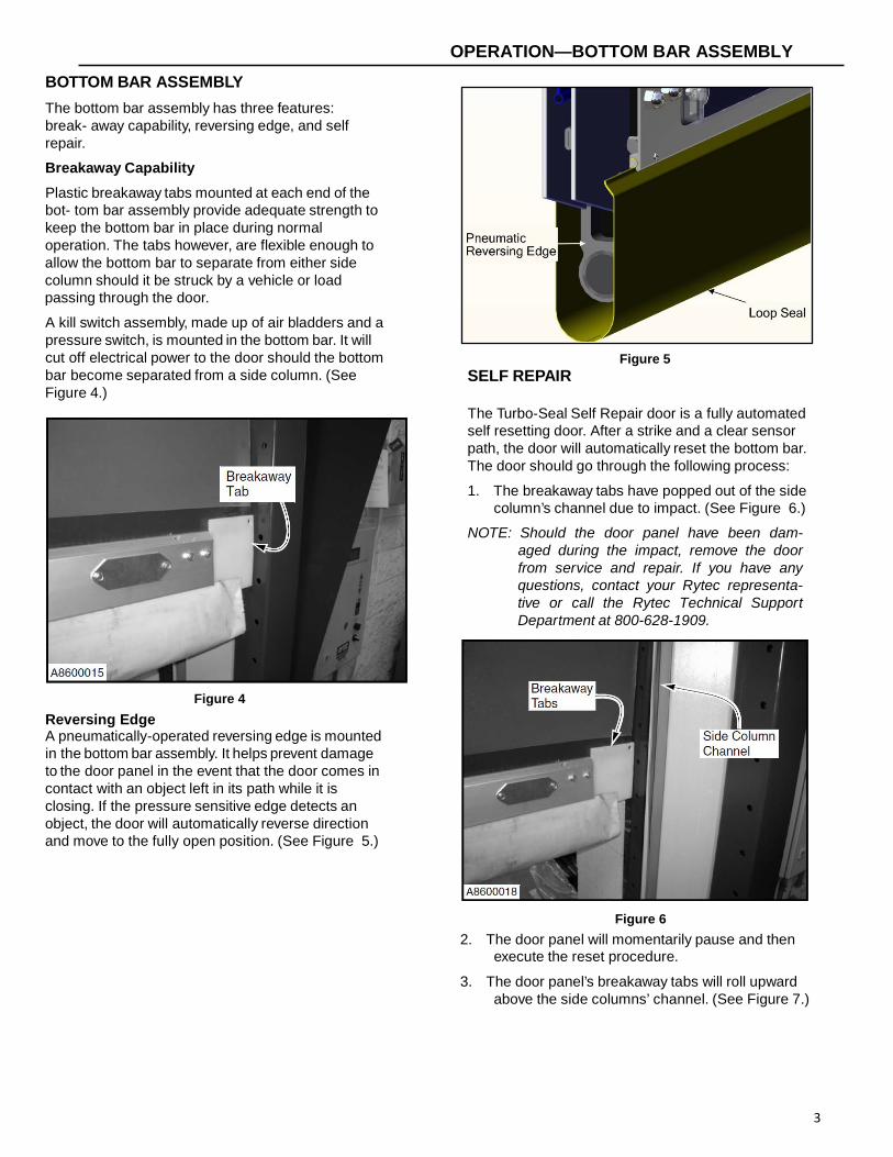
BOTTOM BAR ASSEMBLY
The bottom bar assembly has three features: break- away capability, reversing edge, and self repair.
Breakaway Capability
Plastic breakaway tabs mounted at each end of the bot- tom bar assembly provide adequate strength to keep the bottom bar in place during normal operation. The tabs however, are flexible enough to allow the bottom bar to separate from either side column should it be struck by a vehicle or load passing through the door.
A kill switch assembly, made up of air bladders and a pressure switch, is mounted in the bottom bar. It will cut off electrical power to the door should the bottom bar become separated from a side column. (See Figure 4.)
Figure 4
Reversing Edge A pneumatically-operated reversing edge is mounted in the bottom bar assembly. It helps prevent damage to the door panel in the event that the door comes in contact with an object left in its path while it is closing. If the pressure sensitive edge detects an object, the door will automatically reverse direction and move to the fully open position. (See Figure 5.)
Figure 5
SELF REPAIR The Turbo-Seal Self Repair door is a fully automated self resetting door. After a strike and a clear sensor path, the door will automatically reset the bottom bar. The door should go through the following process:
1. The breakaway tabs have popped out of the side column’s channel due to impact. (See Figure 6.)
NOTE: Should the door panel have been dam- aged during the impact, remove the door from service and repair. If you have any questions, contact your Rytec representa- tive or call the Rytec Technical Support Department at 800-628-1909.
Figure 6
2. The door panel will momentarily pause and then execute the reset procedure.
3. The door panel’s breakaway tabs will roll upward above the side columns’ channel. (See Figure 7.)
4
Figure 7
4. The photo eyes sense if the path is clear of any obstructions.
5. Then the door panel will guide itself into the channel and resume its normal operation. (See Figure 8.)
NOTE: Cycling the door and checking for proper door operation is not required unless prescribed.
Figure 8
NOTE: There is no indicator, (light or horn) to signal that the door is in the repair mode, the display will read “I:060 Ajar Repair”. If the customer requires a signal device it can be added to the system.
The door function is fully automatic, it will reset, rise to the open position, and reinsert the bottom bar according to factory installed parameters. Cycling the door and checking for proper door operation is not required unless prescribed, but an occasional test of the self repair system would ensure its proper operation. Should slight adjustments of the door be needed, please contact Rytec Technical Support at 1-800-628-1909.
POWER DRIVE SYSTEM
The Turbo-Seal Self Repair power drive system consists of a drive motor gearbox assembly and an electric brake system.
The power drive system incorporates an electric brake used to stop the door travel when electrical power to the door is shut off. A manual brake release is provided for manual opening or closing of the door should there be a power failure, or if routine maintenance needs to be done with the power disconnected.(See Figure 9 and Figure 10.)
Figure 9
Figure 10
5
OPERATION—COUNTER BALANCE SYSTEM
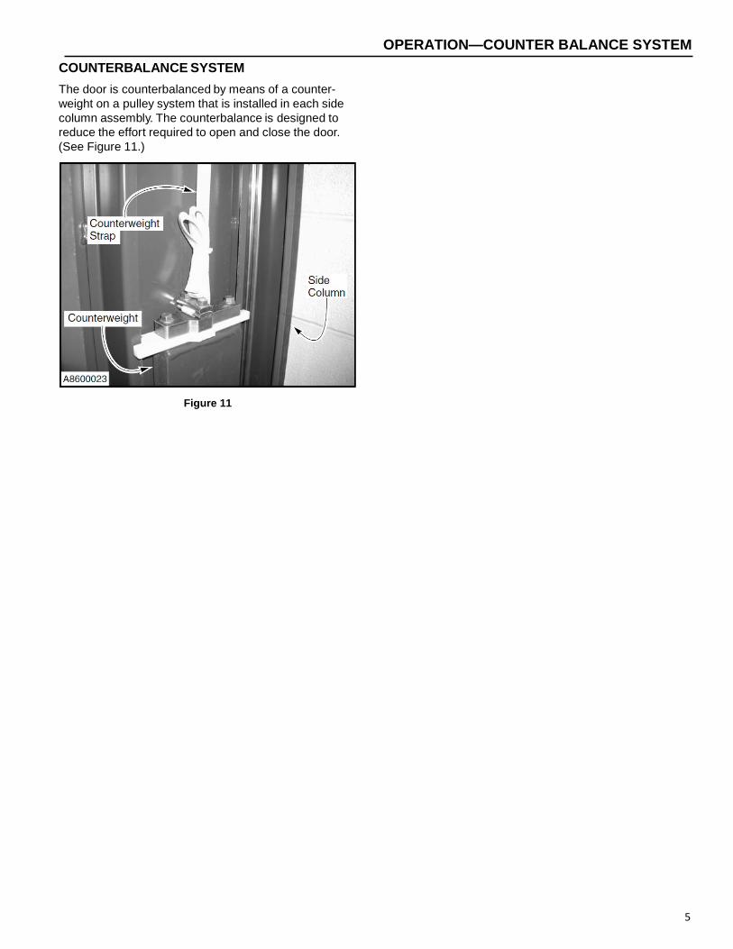
COUNTERBALANCE SYSTEM
The door is counterbalanced by means of a counter- weight on a pulley system that is installed in each side column assembly. The counterbalance is designed to reduce the effort required to open and close the door. (See Figure 11.)
Figure 11
6
Daily Quarterly
Visual Damage Inspection Check Door Operation Reversing Edge Inspection Photo Eye Inspection (Front and Rear)
Hardware Inspection Fabric Inspection Weather Seal Inspection Close Limit Inspection Open Limit Inspection Motor Brake Inspection Bottom Bar Inspection Kill Switch Inspection Counterweight Inspection Counterweight Strap Inspection Activator and Control Panel I ti
NOTE: The following maintenance schedule is recommended for the Rytec Cycle-Plus maintenance program.
DAILY INSPECTION
Visual Damage Inspection
Visually inspect the door to see that components have not been damaged. Example: bent bottom bar assem- bly, torn fabric panel, damage to side columns, etc. (See Figure 12.)
Figure 12
Head Assembly: Inspect for dents or damage that may prevent the door from opening or closing properly.
Door Panel: Inspect panel for holes, tears, and worn areas. If equipped with windows, inspect them for damage or dirt that may impair vision — clean or replace as required.
Side Columns and Covers: Inspect for damage that may prevent the door from operating properly.
Photo Eye: Inspect the lens of each photo eye for damage or dirt that may prevent the photo eyes from working properly — clean or replace as required.
Bottom Bar: Inspect the bottom bar for damaged, missing, or loose hardware. Inspect the yellow vinyl seal along the lower edge of the bottom bar for tears and holes. Inspect the edge itself.
7
Counterweights and Straps: Counterweights must be properly adjusted. Counterweight straps must be in good working condition, securely attached to the coun- terweights and the drum assembly, and tracking prop- erly on all rollers.
Check Door Operation
Run the door through four or five complete cycles to ver- ify that the door is operating smoothly and efficiently, and that binding or unusual noises do not exist. DO NOT continue to operate the door if it is not running properly, as this could compound the damage.
Reversing Edge Inspection
Do not stand under the door panel while testing the door reversing function. If the reversing edge switch is not working prop- erly, the panel could strike the person per- forming the test. Also, do not continue to use the door if the reversing edge is not operating properly.
While the door is running through the down cycle, tap the bottom of the reversing edge. If the reversing edge is operating properly, the door will immediately reverse and run to the fully open position. Push the control panel down key to close the door after the inspection is com- plete. If the reversing edge is not working properly, see “PNEUMATIC REVERSING EDGE SWITCH ADJUST- MENT” on page 13 for the adjustment procedures.
Photo Eye Inspection
NOTE: Photo eyes act as a safety device to pre- vent the door from closing if an object or person is within the photo eye beam. The photo eyes are not meant to be used as door activators.
1. Raise the door to the fully open position by pushing
the up arrow key on the front of the control panel.
2. Break the beam of light on the front side of the door by placing an object between the photo eyes, trans- mitter and receiver.
3. Press the down key on the front of the control panel. The door should not operate.
4. If the photo eyes don’t operate properly, the trans- mitter or receiver may be dirty. Clean as required using window cleaner and a clean soft cloth. If cleaning does not solve the problem, see “PHOTO EYE ADJUSTMENT” on page 15 for adjustment procedures.
5. Repeat the procedure on the back side of the door.
QUARTERLY INSPECTION
The disconnect must be in the OFF posi- tion and properly locked and tagged before performing the following procedure.
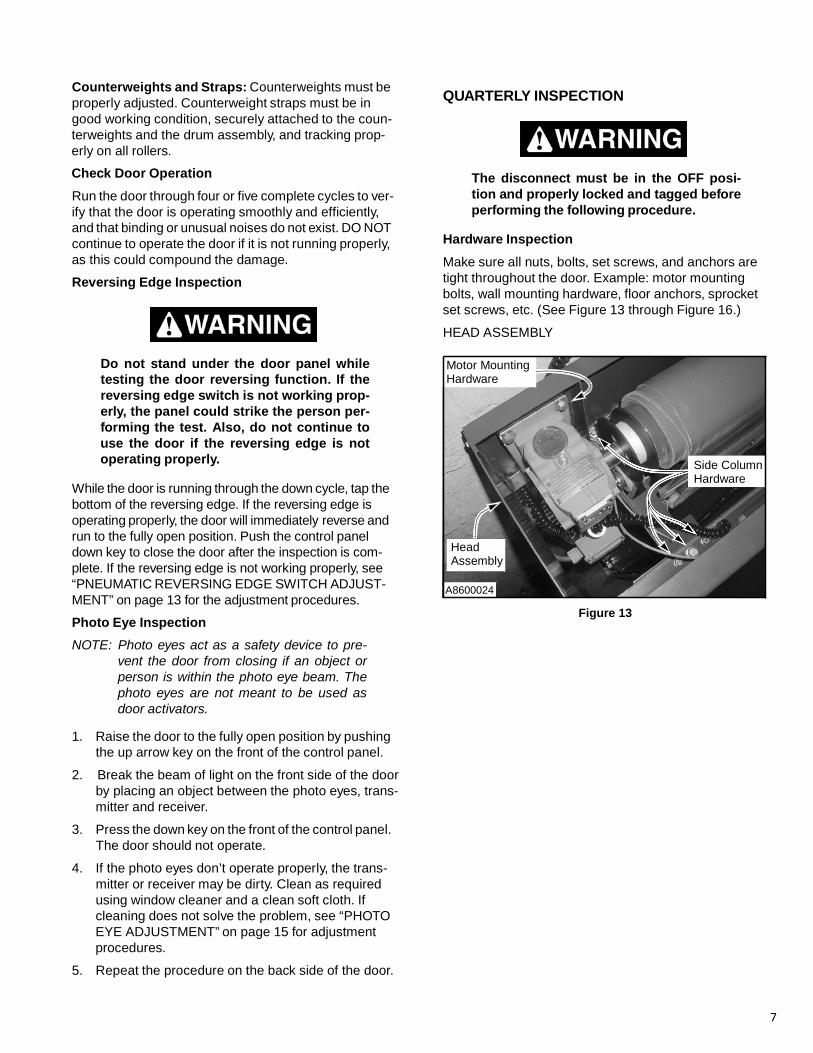
Hardware Inspection
Make sure all nuts, bolts, set screws, and anchors are tight throughout the door. Example: motor mounting bolts, wall mounting hardware, floor anchors, sprocket set screws, etc. (See Figure 13 through Figure 16.)
HEAD ASSEMBLY Motor Mounting Hardware
Side Column Hardware
Head Assembly
A8600024
Figure 13
8
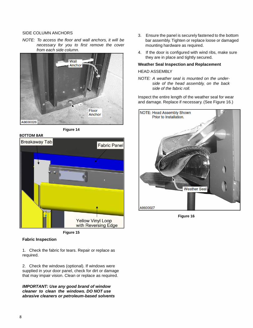
SIDE COLUMN ANCHORS
NOTE: To access the floor and wall anchors, it will be necessary for you to first remove the cover from each side column.
Figure 14
BOTTOM BAR
Figure 15
3. Ensure the panel is securely fastened to the bottom
bar assembly. Tighten or replace loose or damaged mounting hardware as required.
4. If the door is configured with wind ribs, make sure they are in place and tightly secured.
Weather Seal Inspection and Replacement
HEAD ASSEMBLY
NOTE: A weather seal is mounted on the under- side of the head assembly, on the back side of the fabric roll.
Inspect the entire length of the weather seal for wear and damage. Replace if necessary. (See Figure 16.)
Figure 16
Fabric Inspection 1. Check the fabric for tears. Repair or replace as required. 2. Check the windows (optional). If windows were supplied in your door panel, check for dirt or damage that may impair vision. Clean or replace as required. IMPORTANT: Use any good brand of window cleaner to clean the windows. DO NOT use abrasive cleaners or petroleum-based solvents
9
SIDE COLUMNS
Inspect the entire length of both brush seals for wear and damage. Replace if necessary. (See Figure 17.)
Figure 17
If it becomes necessary to replace the brush seal on a side column cover, perform the following procedure.
NOTE: Brush seals may be replaced one at a time.
1. Remove the cover from the side column.
2. Remove socket head cap screws from channel half.
3. Remove channel from side column.
4. Remove rivets from brush seal. (See Figure 18.)
Figure 18
5. Remove the old brush seal by sliding it out of the track. 6. Slide a new brush seal into the track. NOTE: A total of four screws are used, two at each end of the brush seal. 7. Screw the track at each end to lock the new brush seal
in place.
Door Limit Inspection
CLOSE LIMIT With the door in the closed position, check the yellow vinyl loop on the bottom bar. It should be in the position shown in Figure 19.
Damage to the rubber reversing edge or other bottom bar parts can occur if the door seal is allowed to seal too tightly against the floor. (See Figure 19.)
Figure 19
If the reversing edge does not seal properly against the floor, see the Rytec System 4 Drive & Control Installa- tion & Owner’s Manual for proper adjustment procedure.
OPEN LIMIT
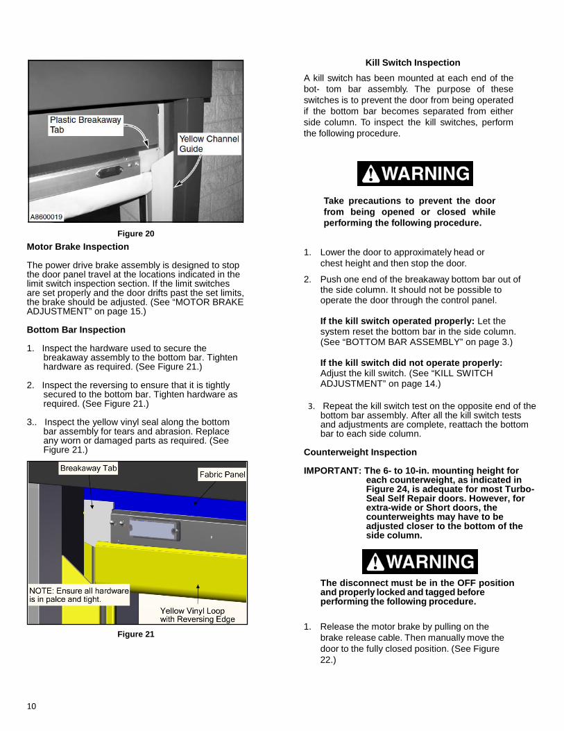
The open limit switch should be adjusted so that the door travel allows the bottom bar assembly to stop approximately with a minimum of half the plastic break- away tab into the yellow channel guide. (See Figure 20.)
10
Figure 20
Motor Brake Inspection The power drive brake assembly is designed to stop the door panel travel at the locations indicated in the limit switch inspection section. If the limit switches are set properly and the door drifts past the set limits, the brake should be adjusted. (See “MOTOR BRAKE ADJUSTMENT” on page 15.) Bottom Bar Inspection 1. Inspect the hardware used to secure the
breakaway assembly to the bottom bar. Tighten hardware as required. (See Figure 21.)
2. Inspect the reversing to ensure that it is tightly
secured to the bottom bar. Tighten hardware as required. (See Figure 21.)
3.. Inspect the yellow vinyl seal along the bottom bar assembly for tears and abrasion. Replace any worn or damaged parts as required. (See Figure 21.)
Figure 21
Kill Switch Inspection
A kill switch has been mounted at each end of the bot- tom bar assembly. The purpose of these switches is to prevent the door from being operated if the bottom bar becomes separated from either side column. To inspect the kill switches, perform the following procedure.
Take precautions to prevent the door from being opened or closed while performing the following procedure.
1. Lower the door to approximately head or
chest height and then stop the door.
2. Push one end of the breakaway bottom bar out of the side column. It should not be possible to operate the door through the control panel.
If the kill switch operated properly: Let the system reset the bottom bar in the side column. (See “BOTTOM BAR ASSEMBLY” on page 3.)
If the kill switch did not operate properly: Adjust the kill switch. (See “KILL SWITCH ADJUSTMENT” on page 14.)
3. Repeat the kill switch test on the opposite end of the
bottom bar assembly. After all the kill switch tests and adjustments are complete, reattach the bottom bar to each side column.
Counterweight Inspection IMPORTANT: The 6- to 10-in. mounting height for
each counterweight, as indicated in Figure 24, is adequate for most Turbo-Seal Self Repair doors. However, for extra-wide or Short doors, the counterweights may have to be adjusted closer to the bottom of the side column.
The disconnect must be in the OFF position and properly locked and tagged before performing the following procedure.
1. Release the motor brake by pulling on the
brake release cable. Then manually move the door to the fully closed position. (See Figure 22.)
11
Counterweight Strap Inspection
Manual Brake Release
The disconnect must be in the OFF posi- tion and properly locked and tagged before performing the following procedure.
A8600022
Figure 22
1. Remove the side column covers.
2. Inspect both counterweight straps for tears and frayed edges. Also inspect each strap for abrasions that might indicate a seized pulley or misaligned drum roll. (See Figure 24.)
Inspect the entire length of each strap by releasing 2. Remove the cover from each side column.
3. Measure the distance between the top of each counterweight and the top of its associated side col- umn. The clearance between each weight and col- umn must be at least 2 in.
If an adjustment is necessary, move the door to the fully open position. After placing a support block under the counterweight, readjust the strap, as required, until the 2-in. clearance is achieved.
If either counterweight requires an adjustment, see “COUNTERWEIGHT ADJUSTMENT” on page 18.
4. Manually move the door in the fully open position.
5. Measure the distance between the bottom of each counterweight and the base of the side column. The distance between each counterweight and associ- ated base plate should be 6- to 10-in. (See Figure 23.)
If either counterweight requires an adjustment, see “COUNTERWEIGHT ADJUSTMENT” on page 16.
the motor brake and manually moving the door to the fully open and closed positions.
If either strap needs to be replaced, see “COUNTERWEIGHT STRAP REPLACEMENT” on page 17.)
Counterweight Strap
Side Column
Counterweight
A8600023
6 to 10 in.
A8600010
Figure 23
Figure 24
Activator and Control Panel Inspection
1. Inspect all warning and safety labels. All labels should be intact, clean, and clearly legible. Replace any label when necessary.
2. Operate the door five or six complete open and close cycles with each activator installed with the door. Make any necessary adjustments or repairs. Refer to the associated manual supplied with each activator installed with your door.
Typical activators may include a floor loop, pull cord, push button, motion detector, radio control, or photo eye. The door open cycle is controlled by the activator. The door close cycle can be controlled by an activator or by a timer internal to the control panel.
12
3. Check the control panel for proper operation. If an
adjustment or repair is necessary, refer to the Rytec System 4 Drive & Control Installation & Owner’s Manual that was shipped with your control panel.
Electrical Connection Inspection
The disconnect must be in the OFF posi- tion and properly locked and tagged before performing the following procedure.
1. Turn off power to the door.
2. Inspect all electrical connections to the power drive system. All connections must be secure and tight.
3. Inspect the electrical connections in the junction
box located in the head assembly. All connections must be secure and tight.
4. For the proper control panel electrical connection inspection procedure, see the Rytec System 4 Drive & Control Installation & Owner’s Manual.
Lubrication
The disconnect must be in the OFF posi- tion and properly locked and tagged before performing the following procedure.
1. Turn off power to the door.
2. Remove the hood and the side covers (if hood and covers are installed).
3. Pillow Block Bearings: The drum roll is supported by a pillow block bearing located at the opposite end of the drive motor gearbox assembly. The pillow block has a grease fitting. (See Figure 25.)
The bearing should be lubricated quarterly using a lithium-based grease conforming to NLGI grade 2 standard.With an approved operating temperature range of –30°F to 200°F
Figure 25.
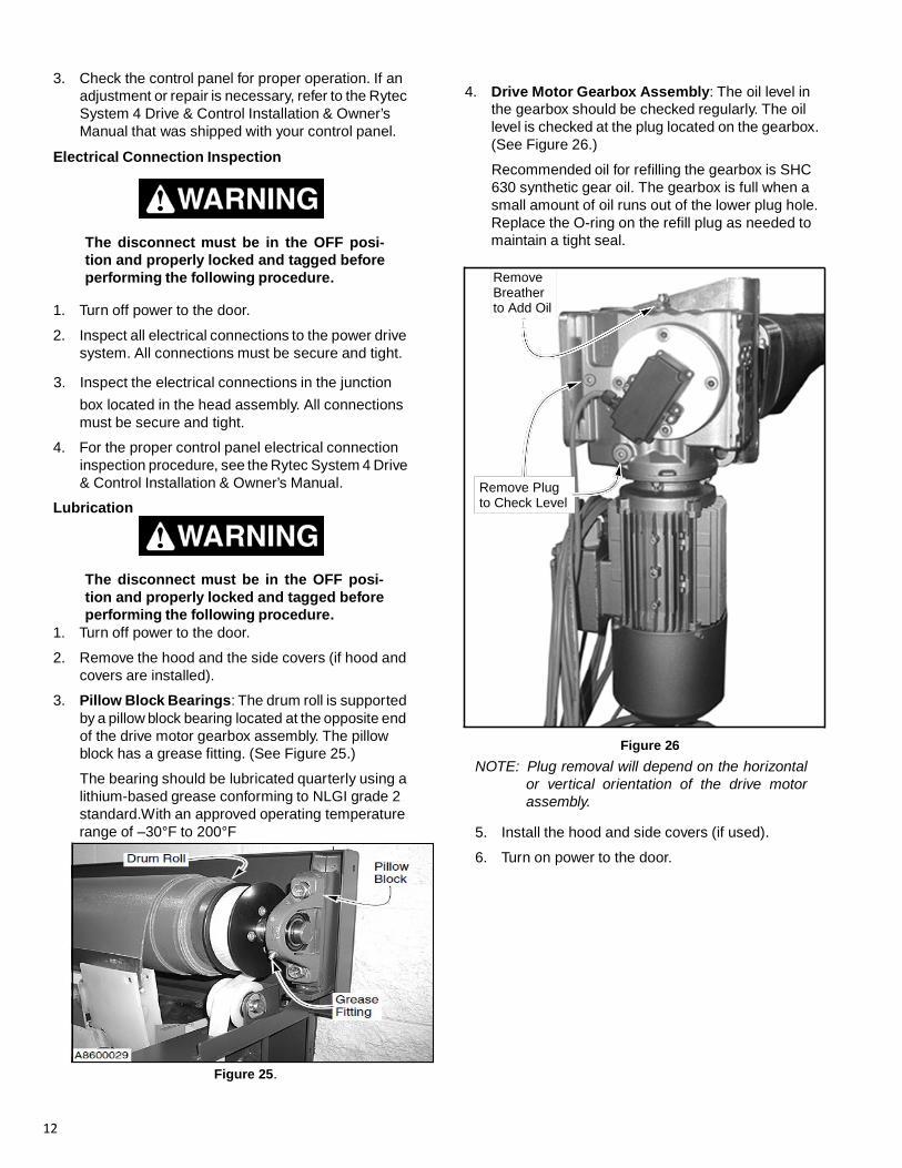
4. Drive Motor Gearbox Assembly: The oil level in
the gearbox should be checked regularly. The oil level is checked at the plug located on the gearbox. (See Figure 26.)
Recommended oil for refilling the gearbox is SHC 630 synthetic gear oil. The gearbox is full when a small amount of oil runs out of the lower plug hole. Replace the O-ring on the refill plug as needed to maintain a tight seal.
Remove Breather to Add Oil
Remove Plug to Check Level
Figure 26 NOTE: Plug removal will depend on the horizontal
or vertical orientation of the drive motor assembly.
5. Install the hood and side covers (if used).
6. Turn on power to the door.
13
Wall Anchor Inspection
1. Turn off power to door.
The disconnect must be in the OFF posi- tion and properly locked and tagged before performing the following procedure.
2. Gain access to wall anchors.
3. Inspect for loose or worn wall anchor(s).
4. Tighten, repair or replace wall anchor(s) as needed.
NOTE: Remove door from service if any repairs are needed. All repairs must be done in accordance with building code.
5. Restore power to the door and return to service.
ADJUSTMENTS
PNEUMATIC REVERSING EDGE SWITCH ADJUSTMENT
Do not stand under the door panel when making check. If reversing edge switch is not working properly, panel could strike person performing check.
To check the reversing edge switch operation, run the door through the down cycle. As the door is lowering, tap the bottom of the reversing edge. If the reversing edge switch is operating properly, the door should immediately reverse and run to the full-open position. Reset the control system after the check is completed.
If the door does not reverse, check the air bleed and sensitivity of the reversing edge switch.
Reversing Edge Switch Air Bleed Check
1. The reversing edge switch is located inside the bot- tom bar assembly. To inspect and/or adjust the switch, remove the access cover from the face of the bottom bar assembly. (See Figure 27.)
Figure 27
2. Make sure the clear PVC hose is in tight contact
with the air input post so that air leakage cannot occur and that vibration will not cause the hose to fall off. not kinked. (See Figure 28.)
3. The air bleed has been set at the factory and should not require adjustment. To check the air bleed, turn the air bleed adjustment screws located on the front and back of the switch fully clockwise but do not overtighten. Then turn the screws back counter- clockwise one full turn. (See Figure 28.)
Figure 28
Reversing Edge Switch Sensitivity Adjustment
1. The reversing edge switch is a normally open con- tact. The PVC hose is on the lower air input post. To adjust the switch, first remove the wires and resistor from the contact terminals and attach an ohmmeter across the two terminals. (See Figure 29.)
2. Turn the adjustment screw, located on the face of the switch, clockwise or counterclockwise until con- tinuity is achieved. Then turn the screw ³⁄₄ turn counterclockwise. Ohmmeter should no longer show continuity. Turning the screw counterclock- wise decreases sensitivity. Turning the screw clock- wise increases sensitivity. (See Figure 29.)
Figure 29
14
3. Reattach resistor and wires and then replace the access cover on the bottom bar.
NOTE: If the reversing edge is set too sensitive, the door may reverse direction during the closing cycle, without the reversing edge coming in contact with an object. If this occurs, readjust the reversing edge switch.
KILL SWITCH ADJUSTMENT
Air Bleed Adjustment
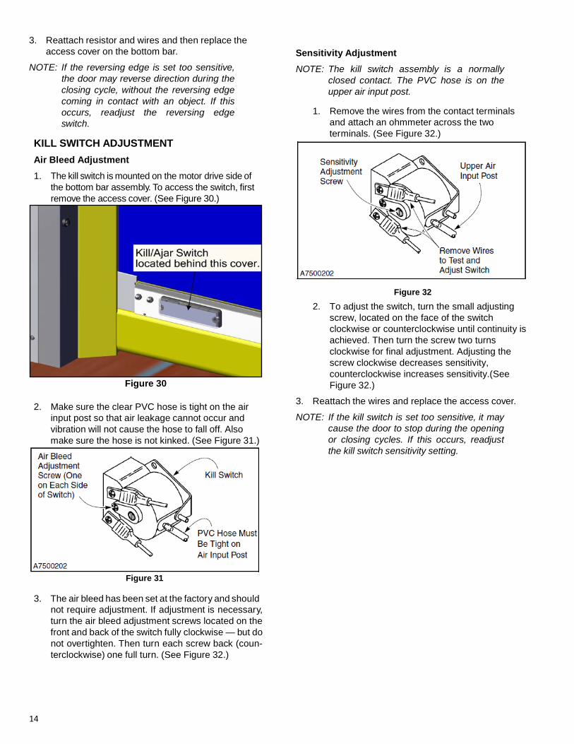
1. The kill switch is mounted on the motor drive side of the bottom bar assembly. To access the switch, first remove the access cover. (See Figure 30.)
Figure 30
2. Make sure the clear PVC hose is tight on the air
input post so that air leakage cannot occur and vibration will not cause the hose to fall off. Also make sure the hose is not kinked. (See Figure 31.)
Figure 31
3. The air bleed has been set at the factory and should
not require adjustment. If adjustment is necessary, turn the air bleed adjustment screws located on the front and back of the switch fully clockwise — but do not overtighten. Then turn each screw back (coun- terclockwise) one full turn. (See Figure 32.)
Sensitivity Adjustment
NOTE: The kill switch assembly is a normally closed contact. The PVC hose is on the upper air input post.
1. Remove the wires from the contact terminals
and attach an ohmmeter across the two terminals. (See Figure 32.)
Figure 32
2. To adjust the switch, turn the small adjusting screw, located on the face of the switch clockwise or counterclockwise until continuity is achieved. Then turn the screw two turns clockwise for final adjustment. Adjusting the screw clockwise decreases sensitivity, counterclockwise increases sensitivity.(See Figure 32.)
3. Reattach the wires and replace the access cover.
NOTE: If the kill switch is set too sensitive, it may cause the door to stop during the opening or closing cycles. If this occurs, readjust the kill switch sensitivity setting.
IMPORTANT: The photo eyes on the standard and freezer doors have set sensitivity settings and cannot be adjusted. Contact the Rytec Technical Support Department for further questions.
A set of photo eyes contains one receiver module and one emitter module. Each one is mounted in a bracket in the side column. The cutout in the bracket is an exact fit for the photo eye; therefore, adjustments are minimal. If the yellow alignment light on the receiver is not lit, per- form the following procedures:
• Check for obstruction in the path of the photo eyes.
• Clean lens on photo eyes.
• Check electrical connections.
• If needed, adjust mounting bracket(s).
NOTE: If any of the procedures listed above did not work, troubleshoot system and replace parts as necessary.
Figure 33
MOTOR BRAKE ADJUSTMENT
1. Turn off the power to the door.
The disconnect must be in the OFF posi- tion and properly locked and tagged before performing the following procedure.
2. Loosen the retaining bolts securing the brake dust
cover to the motor assembly. Remove the cover. (See Figure 34.)
Figure 34
3. Remove sealing band. (See Figure 35.)
Figure 35
4. Using a feeler gauge and a nut driver, adjust the retaining nuts until you achieve the proper air-gap pf 0.010 – 0.024 in. See Figure 36 & 37.)
Figure 36
16
ADJUSTMENTS—COUNTERWEIGHT ADJUSTMENT
All nuts must be equally adjusted or the brake mechanism will wear unevenly.
Figure 37
5.. Reinstall the dust cover and the manual brake release lever.
6. Restore power to the door and perform operations check.
COUNTERWEIGHT ADJUSTMENT
1. Raise the door panel to the fully open position.
2. Remove the side column covers.
3. Turn off power to the door.
The disconnect must be in the OFF posi- tion and properly locked and tagged before performing the following procedure.
NOTE: The 6- to 10-in. dimension shown in
Figure 38 is adequate for most Turbo-Seal Self Repair doors. However, for some very wide or short doors, the counterweight may have to be adjusted closer to the bot- tom of the side column. Also, make sure the counterweight guides are behind the conduit guides located in the side column.
4. With the door panel in the fully open position, the
counterweights should be positioned 6 to 10 in. above the bottom of the side column. (See Figure 38.)
Figure 38
5. To adjust the counterweights, securely block the counterweights in the position indicated in
Counterweights must be securely blocked and the fabric roll locked (motor brake set) before any adjustments can be made.
6. Remove the tape wrapped around the end of the
counterweight strap.
7. Loosen the clamp bars that secure the strap to the counterweight. (See Figure 39.)
Figure 39
8. Raise or lower the counterweight by adjusting the strap through the clamp bars as required.
17
9. Secure the strap by tightening the clamp bars.
10. Wrap tape around the end of the strap to prevent it from fraying.
11. Remove the blocking from under the counterweight.
NOTE: Use care when removing the blocking to ensure the strap does not come off of the roller. The strap can become pinched between the roller and the roller bracket, which can prevent the door from moving. Also, the strap can be cut by coming in contact with the edges of the roller.
Take precautions to prevent the door from being operated as you perform the follow- ing procedure. Also, be cautious around the moving parts exposed in the side col- umns.
12. Turn on the power to the door and cycle the door
panel several times.
NOTE: With the door fully closed, there should be 2 in. of clearance between the top of the counterweight and the upper end of the side column. With the door fully open, the counterweight guides must be behind the side column conduit guides. Make any necessary adjustments to properly posi- tion either counterweight.
13. Check the position of each counterweight with the
door in the fully open and closed positions. Make any necessary adjustments.
14. Once the counterweights are adjusted, install the side column covers.
REPLACEMENT PROCEDURES COUNTERWEIGHT STRAP REPLACEMENT 1. Raise the door to the fully open position.
The disconnect must be in the OFF posi- tion and properly locked and tagged before performing the following procedure.
2. Turn off power to the door. 3. Make sure the motor brake is set and locked. 4. Remove the hood and the side covers (if hood and
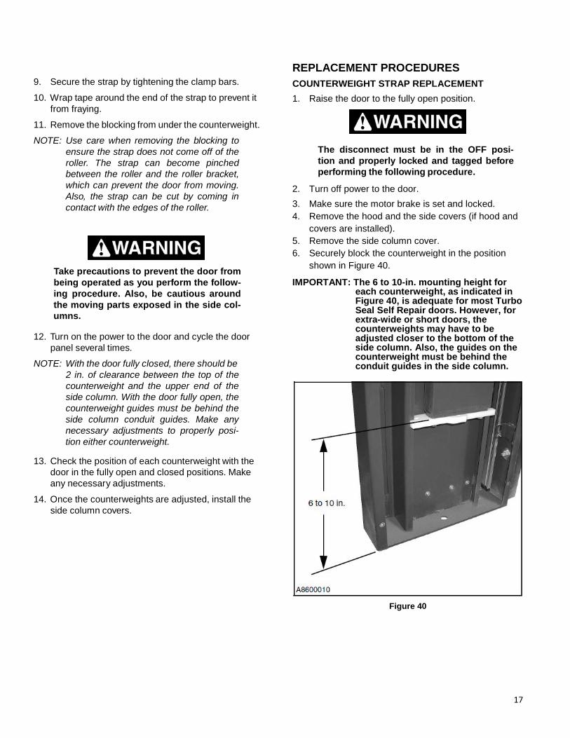
covers are installed). 5. Remove the side column cover. 6. Securely block the counterweight in the position
shown in Figure 40.
IMPORTANT: The 6 to 10-in. mounting height for each counterweight, as indicated in Figure 40, is adequate for most Turbo Seal Self Repair doors. However, for extra-wide or short doors, the counterweights may have to be adjusted closer to the bottom of the side column. Also, the guides on the counterweight must be behind the conduit guides in the side column.
Figure 40
18
a
A counterweight can weigh in excess of 100 pounds. Make sure that safe handling procedures are followed and that each counterweight is securely supported during the following procedure. If not handled properly, a counterweight can damage door components and cause serious personal injury.
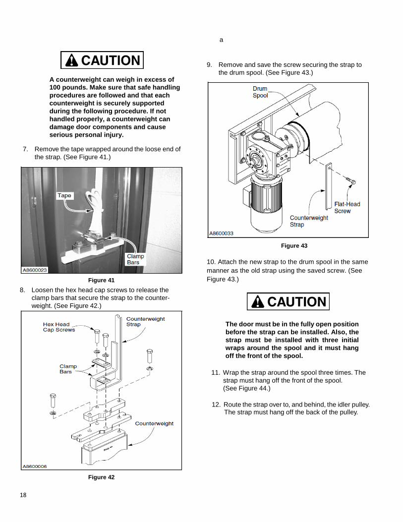
7. Remove the tape wrapped around the loose end of the strap. (See Figure 41.)
Figure 41 8. Loosen the hex head cap screws to release the
clamp bars that secure the strap to the counter- weight. (See Figure 42.)
Figure 42
9. Remove and save the screw securing the strap to
the drum spool. (See Figure 43.)
Figure 43
10. Attach the new strap to the drum spool in the same manner as the old strap using the saved screw. (See Figure 43.)
The door must be in the fully open position before the strap can be installed. Also, the strap must be installed with three initial wraps around the spool and it must hang off the front of the spool.
11. Wrap the strap around the spool three times. The
strap must hang off the front of the spool. (See Figure 44.)
12. Route the strap over to, and behind, the idler pulley.
The strap must hang off the back of the pulley.
19
Figure 44
13. Attach the new strap to the counterweight by routing
the strap through the clamp bars in the same man- ner as the old strap. Tighten the hex screws to clamp the strap to the weight. (See Figure 45.)
Figure 45 14. Remove the blocking from under the counterweight.
15. Adjust the counterweight as required. (See “COUN- TERWEIGHT ADJUSTMENT” on page 16.)
16. Wrap tape around the loose end of the strap to pre- vent it from fraying. Cut off any excess strap hang- ing past the taped end. Then, to hold the loose end of the strap out of the way, tape it to the main length of strap.
Take precautions to prevent the door from being operated as you perform the follow- ing procedure. Also, be cautious around moving parts exposed in the side columns.
17. Turn on the power to the door.
18. Cycle the door several times to verify that the strap is operating correctly. Verify that the counterweight is properly adjusted. Then make any necessary adjustments (with power turned off).
19. After all adjustments are complete; reinstall the hood and the side covers (if hood and covers were installed) and the side column cover.
20
NOTES
21
PARTS LIST—PARTS ORDERING INFORMATION PARTS LIST
PARTS ORDERING INFORMATION
How To Order Parts
1. Identify the parts required by referring to the follow- ing pages for part numbers and part descriptions.
2. To place an order, contact your local Rytec repre- sentative or the Rytec Technical Support Depart- ment at: 800-628-1909 or 262-677-2058 (fax). Rytec Corporation also has an on-line store at WWW.Rytecparts.com access to this on-line store requires an invitation from Rytec. The on-line store is open 24/7, 365 days. Some items are available to ship next day. Not all Rytec parts are carried in the on-line store.
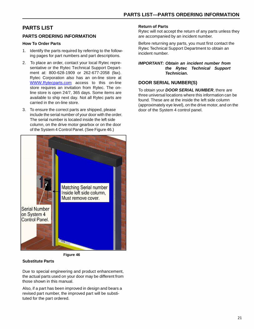
3. To ensure the correct parts are shipped, please include the serial number of your door with the order. The serial number is located inside the left side column, on the drive motor gearbox or on the door of the System 4 Control Panel. (See Figure 46.)
Return of Parts Rytec will not accept the return of any parts unless they are accompanied by an incident number.
Before returning any parts, you must first contact the Rytec Technical Support Department to obtain an incident number. IMPORTANT: Obtain an incident number from
the Rytec Technical Support Technician.
DOOR SERIAL NUMBER(S)
To obtain your DOOR SERIAL NUMBER, there are three universal locations where this information can be found. These are at the inside the left side column (approximately eye level), on the drive motor, and on the door of the System 4 control panel.
Figure 46
Substitute Parts
Due to special engineering and product enhancement, the actual parts used on your door may be different from those shown in this manual.
Also, if a part has been improved in design and bears a revised part number, the improved part will be substi- tuted for the part ordered.
RYTEC TECHNCIAL KNOWLEDGE CENTER RYTEC TECHNICAL KNOWLEDGE CENTER At WWW.Rytecdoors.com under the “Customer Support” tab a link to the Rytec Technical Knowledge Center can be found. This knowledge center contains on-line manuals, service bulletins and video presentations of various Rytec models and repair information.
RYTEC ON-LINE WEBSTORE Rytec Corporation in partnership with Amazon have developed on on-line webstore for purchasing Rytec replacement parts Access to the Rytec webstore is by invitation only. Invitations are processed through the following e-mail address, [email protected] . Please include name and contact information (account holder). All inquiries will be reviewed however, Rytec maintains the authority to grant or deny access to the webstore at all times. The Rytec webstore is open 24/7/365. Parts available on-line require a credit card for purchase. Items in stock routinely ship the same day. The account is strictly for the account holder. All ship to, bill to and ordering information is the responsibility of the account holder. Currently, over one hundred Rytec parts are available at the on-line store. Shipping rates for the products on line are the lowest rates available. RETURNS POLICY FOR ON-LINE WEBSTORE Customer may return new, unopened items with 30 days of delivery for a full refund.
Items should be returned in their original packaging. The buyer will need to pay for the return shipments; return shipping costs will be refunded if the return is a result of merchant or Amazon error.
All refunds go to the original purchaser. A full refund will be due provided the return is received within the return window.
Replacements and exchanges are not supported; customers can return their original order for a refund and create a new order for the replacement.
Items classified as hazardous are not returnable. Please contact merchant for issues concerning these items.
Instructions on how to return items:
1. Visit return center within your account to create a return merchandise authorization.
2. Print the returns slip and the shipping label.
3. Include the returns slip inside the box and affix the shipping label to the box.
PARTS LIST – BRAKE CABLE & ENCODER BRAKE CABLE & ENCODER
ALWAYS INCLUDE SERIAL NUMBER OF DOOR WHEN PLACING ORDER Due to product enhancement, the actual parts on your door may be different from those shown in this manual.
24
PARTS LIST – MOTOR ASSEMBLY & HARDWARE MOTOR ASSEMBLY & HARDWARE
ALWAYS INCLUDE SERIAL NUMBER OF DOOR WHEN PLACING ORDER
Due to product enhancement, the actual parts on your door may be different from those shown in this manual.
25
PARTS LIST—COUNTERWEIGHT STRAP & HARDWARE COUNTERWEIGHT STRAP & HARDWARE
ALWAYS INCLUDE SERIAL NUMBER OF DOOR WHEN PLACING ORDER Due to product enhancement, the actual parts on your door may be different from those shown in this manual.
26
PARTS LIST – SIDE COLUMN TRACKS & COVERS SIDE COLUMN TRACKS & COVERS
ALWAYS INCLUDE SERIAL NUMBER OF DOOR WHEN PLACING ORDER Due to product enhancement, the actual parts on your door may be different from those shown in this manual.
27
PARTS LIST—COUNTERWEIGHT HARDWARE COUNTERWEIGHT HARDWARE
ALWAYS INCLUDE SERIAL NUMBER OF DOOR WHEN PLACING ORDER Due to product enhancement, the actual parts on your door may be different from those shown in this manual.
28
PARTS LIST – HEAD ASSEMBLY HARDWARE HEAD ASSEMBLY HARDWARE
ALWAYS INCLUDE SERIAL NUMBER OF DOOR WHEN PLACING ORDER Due to product enhancement, the actual parts on your door may be different from those shown in this manual.
29
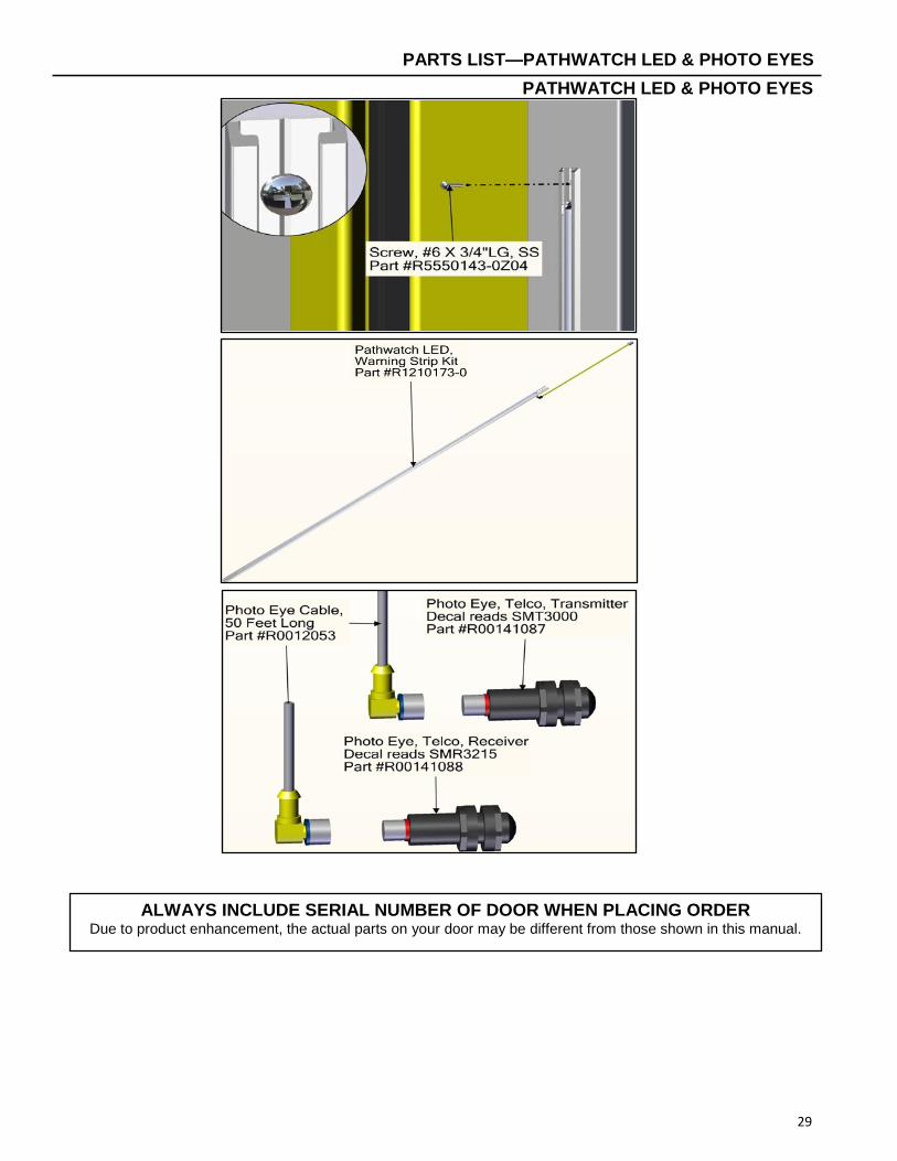
PARTS LIST—PATHWATCH LED & PHOTO EYES PATHWATCH LED & PHOTO EYES
ALWAYS INCLUDE SERIAL NUMBER OF DOOR WHEN PLACING ORDER Due to product enhancement, the actual parts on your door may be different from those shown in this manual.
30
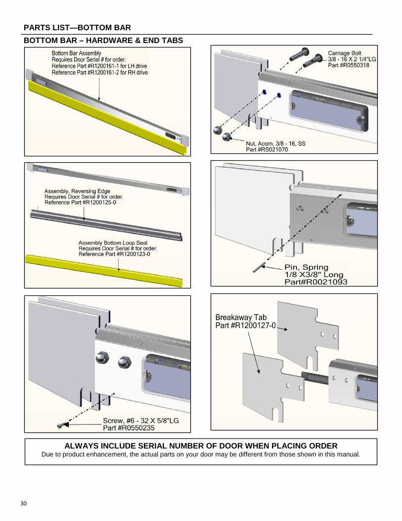
PARTS LIST—BOTTOM BAR BOTTOM BAR – HARDWARE & END TABS
ALWAYS INCLUDE SERIAL NUMBER OF DOOR WHEN PLACING ORDER Due to product enhancement, the actual parts on your door may be different from those shown in this manual.
PARTS LIST – BOTTOM BAR, MOBILE UNIT, BATTERY & HARDWARE BOTTOM BAR, MOBILE UNIT, BATTERY & HARDWARE
31
ALWAYS INCLUDE SERIAL NUMBER OF DOOR WHEN PLACING ORDER Due to product enhancement, the actual parts on your door may be different from those shown in this manual.
PARTS LIST – BOTTOM BAR END BLOCK PARTS BOTTOM BAR END BLOCK PARTS
32
ALWAYS INCLUDE SERIAL NUMBER OF DOOR WHEN PLACING ORDER Due to product enhancement, the actual parts on your door may be different from those shown in this manual.
33
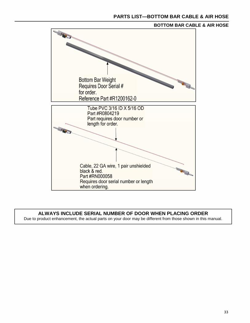
PARTS LIST—BOTTOM BAR CABLE & AIR HOSE
BOTTOM BAR CABLE & AIR HOSE
ALWAYS INCLUDE SERIAL NUMBER OF DOOR WHEN PLACING ORDER Due to product enhancement, the actual parts on your door may be different from those shown in this manual.
PARTS LIST – PANEL ASSEMBLY PANEL ASSEMBLY
34
ALWAYS INCLUDE SERIAL NUMBER OF DOOR WHEN PLACING ORDER Due to product enhancement, the actual parts on your door may be different from those shown in this manual.


![R Y T E C · 2019-12-13 · [Revision: March 15th, 2016, R1091004-0, ™ Rytec Corporation 2015] Turbo Slide ... Seller does not warrant against and is not responsible for, and no](https://static.documents.pub/doc/80x56/5ec4e926e95b671c4c48762a/r-y-t-e-c-2019-12-13-revision-march-15th-2016-r1091004-0-a-rytec-corporation.jpg)


