DC-7700 WARNING..Read all instructions carefully before assembling components and operating sprayer. Incorrect procedure could result in damage to the unit, severe personal injury and/or property damage. When spraying flammable materials, sprayer must be placed at least 20 feet from target in a well- ventilated area. Vapours can be ignited by static discharge or electrical sparks and result in severe personal injury. LEMMER airless sprayers generate high fluid pressure. Improper use could result in an injection injury. OWNER'S MANUAL DC1600, DC2000, DC3100, DC5700, DC7700 VANCOUVER • CALGARY • TORONTO • MONTRÉAL DC-1600n DC-3100 DC-2000 DC-5700
Transcript
1
DC-7700
WARNING..Read all instructions carefully before assembling components and operating sprayer. Incorrect procedure could result in damage to theunit, severe personal injury and/or property damage. When spraying flammable materials, sprayer must be placed at least 20 feet from target in a well-ventilated area. Vapours can be ignited by static discharge or electrical sparks and result in severe personal injury. LEMMER airless sprayers generatehigh fluid pressure. Improper use could result in an injection injury.
TABLE OF CONTENTSSAFETY PRECAUTIONS ...................................................................... 3 & 4TECHNICAL SPECIFICATIONS ...................................................................5PUMP COMPONENTS .................................................................................6ELECTRONIC CONTROLS ..........................................................................7SETTING UP OF UNIT .................................................................................7TIP SELECTION & MAINTENANCE...................................................... 8 & 9HOW TO SELECT TIP SIZE AND PROPER FILTER ................................. 10STARTUP PROCEDURE:
UNIT PRIMING AND FLUSHING .................................................. 11PRIMING UNIT IN PAINT .............................................................. 11TO TURN UNIT OFF ..................................................................... 11
HINTS FOR AIRLESS SPRAYING:PAINTING AND TIP SELECTION ................................................. 12SPRAY PAINTING METHOD ........................................................12
CLEANING INSTRUCTIONS ......................................................................13MAINTENANCE & SERVICE, DC-2000 / 3100 / 4600 & 7700 ........... 14 - 18TROUBLESHOOTING ................................................................................19OTHER QUALITY LEMMER PRODUCTS..................................................20ACCESSORIES FOR LEMMER AIRLESS EQUIPMENT ........................... 21L-60 PARTS ....................................................................................... 22 & 23DC-2000 PARTS & SERVICE ............................................................ 24 & 25DC-3100 & DC-4600 PARTS ............................................................. 26 & 27DC-7700 PARTS ................................................................................ 28 & 29DC-1600 PARTS .........................................................................................30NOTES .......................................................................................................31DISTRIBUTION CENTRES ACROSS CANADA ......................................... 32LEMMER WARRANTY ...............................................................................32
3
SAFETY PRECAUTIONSWARNING
1) Injection hazard : Airless Painting Equipment cancause serious injury if the spray penetrates theskin. Do not point the gun at anyone or any part ofthe body. The tip guard provides some protectionagainst accidental injection injuries, but is mostly awarning device. Never put your hand, fingers orbody over the spray tip. Gloves and clothing do notnecessarily offer any protection either. Keep thegun trigger safety lever in locked postion when notspraying. Always have the tip guard in place whilespraying.In case of penetration seek medical aid immediately!Note to physician: Injection into skin is a serioustraumatic injury. It is important to treat the injurysurgically as soon as possible. Do not delay treat-ment to research toxicity. Toxicity is a concern withsome exotic coatings injected into the bloodstream.Consultation with a plastic surgeon or reconstructivehand surgeon may be advisable. Be prepared to tellthe doctor what fluid was injected.
2) This system is capable of producing 3200 PSI . Toavoid rupture and injury, do not operate this pump withcomponents rated less than 3200 PSI working pressure(including but not limited to spray guns, hose and hoseconnections).
3) Do not spray paints or other inflammable fluidsindoors which have a flash point below 21 degree C, 70degree F. Keep spray area well ventilated. Beforespraying, turn off all pilot lights and open flames.
4) Wear a respirator which is approved for the productbeing sprayed.
5) Do not use halogenated hydrocarbon solvents in thissystem; it contains aluminium parts and may explode.Cleaning agents, coatings, paints, and adhesives maycontain halogenated hydrocarbon solvents. Don't takechances, consult your material supplier to be sure. (ex:methylene chloride and 1,1,1 - Trichlorethane)
6) Caution : When a flammable liquid is sprayed there maybe danger of fire or explosion especially in a closedarea.
7) Caution: Arcing parts. Keep the pump at least 20 feetaway from explosive vapors.
8) Caution: Static electricity can be developed by airlessspraying. Ground unit and object to be sprayed. Onelectric units, unit power cord must be connected to agrounded outlet. Use only three wire extension cords.Static explosion can occur with ungrounded unit.
9) Flush system with spray tip removed. Always uselowest pressure possible.
10) Always follow safety precautions and warnings printedon paint container.
11) Only use spray guns and hoses supplied by Lemmer.User assumes all risk and liability when using spray gunsor hoses not complying with minimum specification andsafety devices of Lemmer Spray Systems Ltd.
12) Inspect hoses before each use. Never use a damagedhose. High pressure in hoses with wear, leaks or splitsmay cause the hose to rupture and cause seriouspersonal injury. Never try to stop or deflect leaks with anypart of your body.
13) Use extreme caution when cleaning spray tip guard.DO NOT try to wipe off build up around the spray tipbefore following shut down procedure. Follow the Shutdown Procedure, then follow the spray tip manufacturer’sinstructions for removing and cleaning the spray tip.
14) Never attempt to change spray tip or leave the unitunattended without first shutting off pump, releasing fluidpressure, and locking the trigger safety lock.
15) Use extreme caution when changing spray tip. Followthe Shut down Procedure, then follow the spray tipmanufacturer’s instructions for changing the spray tip.
ATTENTION1) Risque d’injection de peinture: Le matériel depulvérisation sans air peut entraîner de graves blessuress’il y a pénétration de la peau par la peinture. Ne jamaispointer le pistolet vers une personne ou vers soi-même.La garde de la buse limite le risque de blessuresaccidentelles par injection mais constitue principalementun élément de mise-en-garde. Ne jamais mettre la main,les doigts ou toutes parties du corps contre la buse. Leport de gants et de vêtements n'est pas nécessairementune forme de protection non plus.Laisser le cran de suretédu pistolet en position fermée quand il nést pas utilisé.
Toujours avoir la garde en place pour peindre.En cas d’accident, demander immédiatement des soins médicaux.Note au médicin: La pénétration de peinture dans la peau peut causerde graves blessures. Il est important de traîter la blessure à lachirurgie aussitôt possible. Ne pas retarder le traitement pourrechercher la toxicité. La toxicité peut avoir de graves conséquencesquand certains enduits exotiques son injectés directement dans lesystéme sanguin. Une consultation avec un chirurgien spécialisant enreconstruction de mains serait conseillable. Soyez prêts à décrire aumédecin quel liquide a été injecté.
2) Ce matériel peut produire une pression de 3200 lbf/po2 . Afin d’éviterdes ruptures et des blessures, ne pas utiliser cette pompe avec deséléments dont la pression nominale de service est inférieure à 3200 lbf/po2(y compris les pulvérisateurs, tuyaux flexibles et raccords).
3) Ne jamai s pulvériser à l’interieur un produit inflammable qui a un pointéclair inférieur à 21 degrés C,70 degrés F. L’endroit où vous peinturez doittoujours être bien aéré. Avant de pulvériser s’assurer qu’il n’y a aucuneflamme ou pilot (veilleuse) de fournaise en marche dans l’appartement.
4) Servez-vous d’un masque respiratoire qui est certifié pour le produit quevous pulvérisez.
5) Ne pas utiliser de solvants contenant des hydrocarbures halogénésavec ce matériel. Il contient des particules d'aluminium et peut exploser. Lesagents de nettoyage, enduits, peintures et, adhésifs, peuvent contenir dessolvants contenant des hydrocarbures halogénés. Soyez prudents;consultez votre fournisseur pour les informations nécessaires. (ex:méthylène chloride and 1,1,1 - Trichloréthane)
6) Attention : La pulvérisaton d'un liquide inflammable peut entraîner unrisque d'incendie ou d'explosion, surtout dans les espaces fermés.
7) Attention: Étincelles électriques. Ne pas placer la pompe à moins de 6mètres des vapeurs explosives.
8) Attention : La pression du produit que l’on pulvérise peut produire unecharge électrostatique . Mettre le matériel et l'objet à pulvériser à la terre.Sur les modèles électriques, le cordon électrique doit être attaché à uneprise de courrant reliée à terre. Le cordon de rallonge doit être à 3 fils. Desdécharges d'électricité statique peuvent se produire si le matériel n'est pasmis à la terre.
9) Retirer l'embout de pulvérisation avant de rincer le matériel tout enutilisant une pression aussi basse que possible.
10) Toujours prendre les précautions nécessaires et observer toutes lesconsignes de sécurité figurant sur le pot de peinture.
11) N'utiliser que les pulvérisateurs et les tuyaux flexibles fournis parLemmer. Les personnes qui utilisent des pulvérisateurs et des tuyauxflexibles non conformes aux standards d'utilisation et de sécurité minimumdu fabricant de la pompe le font à leurs propres risques et seront les seulsresponsables.
12) Examiner soigneusement le tuyau avant de s'en servir. Il ne faut jamaisutiliser un tuyau endommagé ou avec des fentes. Un tuyau à haute pressionqui n'est pas en bon état représente un serieux danger de blessure à lapersonne en cas de crevaison soudaine. Il ne faut jamais essayer d'arrêterdes fuites de liquide avec n'importe quelle partie de votre corps.
13) Il est nécessaire d'exercer beaucoup de précaution pendant lenettoyage de la protection de la buse. Ne jamais essayer d'enlever lapeinture qui aurait pu s'accumuler sur la buse avant d'avoir suivi lesconsignes de sécurité concernant le nettoyage et le remplacement de labuse.
14) Ne jamais essayer de changer la buse ou laisser l'appareil sans surveillanceavant d'arrêter le moteur, couper la pression et verrouiller la gâchette dupistolet.
15) Le remplacement d'une buse doit être fait avec beaucoup deprécaution . Référez-vous au PROCÉDÉ D'ENTRETIEN.
HIGH PRESSURE!
INJECTION HAZARD!
4
SAFETY PRECAUTIONS16) Il ne faut jamais essayer de déplacer l'appareil en tirant sur le
tuyau. Il faut aussi éviter tout tortillement du tuyau.17) Les enfants e t le personnes n'ayant aucuneexpérience avec ce genre de pulvérisateur doivent êtresgardés à l'écart de l'appareil et du chantier de travail.18) Quand on décharge des liquides inflammables ilfaut utiliser des pots conducteurs en métal. Quand onrelâche la pression avec le pistolet, une partie métalliquedu pistolet doit être en contact avec le pot en métal munide mise à la terre.19) La protection de la gâchette réduit le risque
d'activement involontaire si on laisse tomber le pistolet ou s'il estfrappé par accident. Ne jamais utiliser le pistolet sans laprotection de gâchette .
20) Procédé à suivre avant tout travail d'entretien ou denettoyage.1) Bloquer la gâchette avec le levier de verrouillage.2) Placer l'interrupteur MARCHE-ARRÊT en position ARRÊT.3) Débrancher le cordon électrique.4) Ouvrir la vanne de mise à l'air libre pour relâcher la pression.Gardez-la ouverte jusqu'au moment où vous êtes prêts à utiliserl'appareil.5) Enlever la buse.6) Débloquer le levier de verrouillage de la gâchette.7) Relâcher le reste de la pression en déchargeant avec lepistolet dans un pot en métal. Quand on relâche la pression, unepartie métallique du pistolet doit être en contact avec le pot enmétal muni de mise à la terre. (Il n'est pas nécessaire d'utiliser unpot avec mise à la terre pour des produits non inflammables,comme par exemple le latex).8) Ramener le levier de verrouillage en position bloquée.
AvertissementCet appariel est équipé d'un disjoncteur à Protection thermique.En cas de surcharge, le disjoncteur automatique coupe le moteurde la source d'alimentation.• Toujours déconnecter le moteur de la source d’alimentation avant detravailler sur l’appareil.• Lorsque le disjoncteur coupe le moteur de la source d’alimentationrelâcher la pression en plaçant le clapet d’amorçage en position“amorçage”.• Placer l’interrupteur MARCHE-ARRÊT en position ARRÊT.Attention: La cause de la surcharge doit être eliminée avant deremettre le moteur en marche.
Données électriques.Si l'on utilise un cordon de rallonge, veillez à ce qu'il soit à 3 fils (avecmise à la terre) et avec certification CSA. Le calibre des fils doit êtresuffisant pour l'ampérage qui est nécessaire pour que l'appareilfonctionne. Voir le tableau ci-dessous indiquant les calibres minimunsrequis selon les différentes longueurs de la rallonge.
Il est important de garder le moteur propre et à l'abri de l'humidité.L'isolation créée par la peinture sèche pourrait le surchauffer etl'endommager.
Ne jamais enlever la broche de la mise à la terre car elle est essentiellepour la slûreté du travail.
16) Do not pull on hoses to move equipment, DO NOT kink or bendthe hose sharply.
17) Keep children or anyone not familiar with airless spraysystems away from equipment and work area.
18) Conductive metal containers must be used whenflushing flammable fluids through the system. Alwaysflush at low pressure with spray tip removed. A metal partof the spray gun must be held firmly against the groundedmetal pail when flushing or relieving pressure from thegun.
19) Trigger guard helps reduce the risk of accidentallytriggering the gun if dropped or bumped. Do not use a spray gunwithout a trigger guard.
20) Shut Down ProcedureAlways follow Shut Down Procedure before starting anytroubleshooting, servicing or cleaning.1) Engage the trigger safety lock in the locked position. Test thetrigger safety lock to ensure the lock is working properly.2) Turn the On/Off switch to the Off position.3) Unplug the electrical cord on the sprayer.4) Open the prime valve to relieve pressure. Leave open untilready to spray or test or clean.5) Remove the spray tip.6) Disengage the trigger safety lock.7) Trigger the gun into a metal pail to relieve any remainingpressure. A metal part of the spray gun should be held firmlyagainst the grounded metal pail when relieving the pressure fromthe gun. (A grounded metal pail is not required for non-flammablessuch as latex.)8) Reset the trigger safety lock to locked position.
WarningThis unit is provided with a thermally protected Reset. If anoverload occurs, the thermally protected automatic reset discon-nects the motor from the power supply.• Always disconnect motor from power supply before working onequipment.• When thermally protected reset disconnects the motor from thepower supply, relieve pressure by turning priming valve to “prime”.• Turn ON-OFF switch to OFF.Caution : The cause of the overload should be corrected beforerestarting.Important: Read and understand these special safety precautionsbefore operating the unit.
Electrical requirementsIf an extension cord is used, make sure it is a 3 conductor type (hasgrounding wire) and is CSA approved.Also make sure that its wire size(AWG) is thick enough to carry the amperage your machine requires.The chart below will show the minimum recommended AWG for specificlengths. See next page for pump specifications.
Remember; keep the motor clean and dry. Paint acts as an insulatorand will cause overheating and/or motor damage.
Do not remove or bend grounding pin under any circumstances, it isessential for safe operation.
INTRODUCTION:We appreciate your decision to purchase a Lemmer professional qualityprofessional paint spraying system and believe you will find it to be thebest sprayer you ever owned.Your Lemmer airless paint machine is capable of spraying a wide varietyof latex, oil-based and alkyd paints, as well as stains, preservatives andother architectural coatings. The material you are spraying will have adirect effect on the amount of pressure required for the optimum patternand coverage to be obtained. We recommend that before actuallybeginning your job, you carefully read this manual and practice with thesprayer until you feel comfortable using it.These Lemmer sprayers are powerful and versatile enough to be usedwith a variety of accessories (extra lenghts of hose, extensions,pressure feed rollers, etc. as shown later in this manual) to make themeven more versatile systems. Ask your supplier about the recommendedaccessories for your particular job.
PUMP TYPE:The Lemmer DC units use a double acting piston pump, with stationarypackings. This gives good service life and is a simple to maintainsystem. The valves are stainless steel balls with tungsten carbide seats,giving very good reliability.Industrial grade DC motors are used in conjunction with reliablepressure control sytems.
PRODUCT SPECIFICATIONSADVANTAGES OF THESE SYSTEMS ARE:• Pump stops working when you do. Minimizes wear.• Accurate spray pattern with minimal overspray.• Minimal or no thinning of paint products.• Pumps straight out of original paint container.• Variable pressure from 0 to 3000 PSI.• Various nozzles are available for slow to fast spraying.• Light weight, compact and portable.• Quiet running and low power consumption.• Steady spraying pressure - minimal fan fluctuations.• Compact paint pump - quick cleaning, less parts to wear.
Capability: All conventional coatings, ie: latex, stain, lacquer, varnish, ink, primer, preservatives and many other architectural coatings, and with theDC-4600 and DC-7700 also heavier coatings such as block filler and some elastomerics and glues.
IMPORTANT NOTICES:Due to the nature of operation of this unit, even though the motor cuts off, or appears to have cut off, it may re-start at any time. Evenonce the switch has been turned off, there will likely be pressure remaining in the system. Do not service the unit unless it h as beenturned off, unplugged and the pressure has been relieved. Pressure is relieved by turning the prime knob counter clockwise and doublechecking by triggering the gun.
DO NOT USE STEEL BRAID paint spray hose! The DC-1600/2000/3100/7700 can only be used with fibre braid hose.
6
PUMP COMPONENTSSPRAY GUN:The spray gun is designed specifically forairless spraying. Since there is nocompressed air to atomize the paint,atomization is accomplished by forcing thepaint at a very high pressure (3200 psi)through a very small hole (.017" diameterfor example). Because of this highpressure, the spray tip and gun valve aremade of tungsten carbide for maximumwear resistance. The gun body is made offorged alloy and anodized for chemicalresistance.As a safety feature, the spray gun can belocked with the trigger safety lever whenyou are not spraying. Be sure to read allwarnings concerning the high pressures ofairless spraying on page 3 & 4.
PISTON PUMP (DC-1600/2000/3100/7700):Uses two sets of packings and two checkvalves in conjunction with an abrasionresistant piston. This forms a doubleacting pump; ie pumps on both up anddown stroke. Both sets of packings arestationary, eliminating costly cylinderwear.
SPEED REDUCER(DC-1600/2000/3100/7700):Consists of a two stage gear reduction inpermanent grease for long life. Allbearings are also permanently greased. Itconverts the high speed output of motorinto very high torque to drive the pump.
MOTOR (DC-1600/2000/3100):Is an industrial grade high speed unit. Itspermanent magnet DC type constructionwithstands construction site powerfluctuations. The higher rpm of this motorresults in a compact and lightweightdesign.
MOTOR (DC-7700):This unit has the most technologically advanced motor available today.In addition to being very compact and lightweight, it also has no brushesor commutator, and it has high torque combined with low amp draw.
PRESSURE CONTROL BOX (DC-1600/2000/3100):A rugged membrane transducer transmits a paint pressure signal to anelectronic relay which then powers the motor. This on-off design has apressure fluctuation of about 200 psi.
PRESSURE CONTROL BOX (DC-7700):A tough solid state pressure transducer combined with a state of the artvariable speed electronic control provides consistant spray pressure.Features include run dry protection and allowing faster priming oncefluid fills the pump. The safety fuse is easy to access from the outside ofthe motor shell. This motor does not require any service.
(trigger shown in horizontallocked position)
locked
unlocked
ImportantTo engage triggersafety lock, turn
lever tab to horizon-tal position. Test
regularily for properfunctioning whilesystem is shut
down.
For modelsL65 & L-50
Figure 1a. - DC-2000 components.
paint pump
motor
pressure control
speed reducer
prime valve
suction system
airless hose
hose rack
heavy duty gun
reversible tip
on / off switch
DC-3100 components.
paint pump
motor
speed reducer
primevalve
suction system
airless hose
Pressure control
heavy duty gun
reversible tip
on / offswitch
For modelL-26
DC-1600 components.
reversible tip
L-26G spray gun
prime valveairless hose
paint pumpsuction system
on / off switch
suction screen
2 to 3 dropsoil daily
2 to 3 dropsoil daily
2 to 3dropsoil daily
7
SETTING UP OF UNITTOOLS NEEDED:2 x 8" or larger crescent wrench
PROCEDURE:1) Remove all system components from the box for assembly.2) Remove protective cap from outlet connection of pump.3) Connect high pressure airless paint hose to pump outlet. Tighten to
approximately 20 ft. lbs.4) Attach the tip assembly to the spray gun.5) Connect the paint hose to the swivel connection of the spray gun.
Tighten 20 ft lbs. Ensure the gun handle is securely hand tightenedto the gun.
6) Double check all connections, the unit is now ready.
Note : The pump contains a preservative oil when you receive it, thatmay drip from the various connections when the protective caps areremoved.
WARNING: INJECTION HAZARD POSSIBLE. DO NOT SPRAYWITHOUT TIP IN PLACE. ALWAYS ENGAGE TRIGGER LOCKBEFORE REMOVING, REPLACING OR CLEANING TIP. NEVER TRYTO CLEAN THE TIP WITH YOUR FINGERS.
To disengage your trigger lock: Your spray gun is shipped from thefactory with the trigger lock in the engaged position (horizontal onthe L-65). To disengage, turn the trigger lock down until it is in avertical position. To engage the trigger lock, turn it back to ahorizontal position.
trigger lock.
Figure 2. - L-65 gun components.
gun handlewith filterinside.hand tightonly!
tip.
tip housing.
trigger guardfor safety. donot remove!
high pressureswivel, 1/4"npt.
PUMP COMPONENTS
motor
pail hook
suction pipe
return hose
speed reducer
paint pump
suction screen
prime valve
pressure control& on / off switch
High pressure filter
Figure 1e. - DC-7700 components.
Figure 1d. - DC-5700 components.
paintpump
motorpressurecontrol
speed reducer
primevalve
suctionsystem
on / offswitch
2 to 3 dropsoil daily
2 to 3 dropsoil daily
8
TIP SELECTIONTIP SELECTION:A standard size .017 tip will give good performance in latex or oil basematerials of moderate viscosities.
The following chart gives a basic idea of what tips the Lemmer sprayerscan handle performance wise and what tip is appropriate for whichmaterial. Gun filter sizing is also included in the chart for handy refer-ence.
For a much more detailed look at tip sizes, please consult the detailedtip chart on page 10.
Tip size Paint type Filter size.011 Lacquers, industrial enamel, red
very thin paints..013 Oil stains, pigmented lacquers, yellow
red oxide primer..015 Normal application of latex, oil base, yellow
stains and , solid color oil stains..017 Fast application of latex paints white
and stains, oil base paints..019 Heavier body latex paints. white.021 Fast application of heavier latex white
paint, smooth block filter whenproperly thinned.
.021 Maximum tip on DC-3100 not req’d
.025 Maximum tip on DC-4600 not req’d
.031 Maximum tip on DC-7700 not req’d
.045 Maximum tip on HP-9500 not req’d
The maximum tip for a pump is the largest tip that will deliver a properpressure for spraying without overworking or overloading. When a tip isused for some period of time, it can wear beyond the maximum for thepump, which will cause low pressure and poor spray pattern.
Stains and thick latex products often cause the most rapid wear of thetip, while clear lacquers and varnishes cause the least wear. Thus tip lifecan vary from as little as 50 gallons to as much as 200 or more,depending on the product being sprayed and the pressure used.
Filters for the gun are picked not because of the type of paint beingused, but to protect a given size of tip. You pick the tip for the type ofpaint and job being done and then choose the filter to protect that tip.The chart on page 10 gives much more detail about tip and filterchoices.
THE TWO MOST IMPORTANT THINGS TO REMEMBER ABOUTTIPS.....
1) Low pressure means longer life, for tips and the pump. Lessoverspray too!
2) Worn tips waste paint and overwork the pump, wearing it outquickly.
Order Number Orifice Fan Fan Flow Tip Zip Tip BB Tip at 1' Angle Ltr/min markL043-091 0.009 2" 10 DEG. 0.26 109L043-092 L038-092 0.009 4" 20 DEG. 0.26 209L043-093 L038-093 0.009 6" 30 DEG. 0.26 309L043-094 L038-094 0.009 8" 40 DEG. 0.26 409L043-095 L038-095* 0.009 10" 50 DEG. 0.26 509L043-096 L038-096* 0.009 12" 60 DEG. 0.26 609
* LTD - Limited supply, special order when stocks are low. Maximum volume discount allowed is 5+.
Tip Selection
9
ZIP TIP & BIG BARREL INFORMATION
Pos. Order # Description1)L043-001 Zip Tip housing (Lemmer)
L043-002 Zip Tip housing (Graco)L043-003 Zip Tip housing (Binks)
2)L043-005 Zip Tip seal kit (includes gasket #3)L043-006 Spring, 3/pkg (not shown separately)
3)L043-008 Nylon gasketL043-009 Tube of 8x nylon gaskets
4)L043-*** Zip Tip - see chart
32
1
4
Pos. Order # Description1)L038-001 BB Tip housing (Lemmer)
L038-002 BB Tip housing (Graco)2)L038-007 Metal seal3)L038-006 Gasket (standard)
L038-008 Lacquer Gasket (optional)4)L038-*** Tip - see chart
32
14
Zip Tip
Big Barrel
Big Barrel Tip Features:Fast Tip Size Changes - no tools required.Versatility - Interchangeable with G big barrel tips.Long Seal Life - withstands harsh solvents - won't swell or leak even in
severe abrasives - replaces in minutes.Replacement Seal - is included with each new tip.Venturi-Guard - less paint accumulation - helps protect against accidental
injection and prevents tip from slipping out of position.Diffuser - safer unclogging in clean-out position.
Zip Tip Features:Fast Tip Size Changes - no tools required.Long Seal Life - withstands harsh solvents - won't swell or leak even with
small tips - replaces in minutes.Tip Rotates Easily - even under “high pressure” clog-up.Venturi-Guard - less paint accumulation - helps protect against accidental
injection and prevents tip from slipping out of position.Patented Diffuser - safer unclogging in clean-out position.
How to Operate Parts Lists
To operate:When tip plugs rotate the tip handle 180˚. Trigger the gun and line pressure
will purge clog.
Clean Position
Spray Position
To change tips:Rotate tip 90˚.Remove from housing.Install new tip.Rotate 90˚ to spray position.
To change seal assembly:Relieve line pressure and set gun safety.Remove tip housing from gun.Remove tip from housing.Press seal assembly with gasket out of housing. (On the Zip Tip type you can
use the tip as a tool for pressing).Install tip into housing.Lubricate and insert new seal ass'y through back of housing (press firmly to
insure seal is tight against tip shaft).Insert gasket. Install unit on gun. Tighten gun nut.
10
HOW TO SELECT TIP SIZE AND PROPER FILTER(BASIC INFORMATION)
The two most important things to remember about tips.....1) Low pressure means longer life, for tips and the pump. Less overspray too!2) Worn tips waste paint and overwork the pump, causing premature pump wear. The maximum tip for a pump
is the largest tip that will deliver a proper pressure for spraying without overworking or overloading. When atip is used for some period of time, it can wear beyond the maximum size recommended for the pump, whichwill cause low pressure and poor spray pattern.• Stains and thick latex products often cause the most rapid wear of the tip, while clear lacquers and var-nishes cause the least wear. Thus tip life can vary from as little as 50 gallons to as much as 200 or more,depending on the product being sprayed and the pressure used.• Filter screen mesh for the gun or pump are picked not because of the type of paint being used, but to protecta given size of tip. Pick the tip for the type of paint and job being done and then choose the filter to protectthat tip.
Fan Size (measured at 1 foot)Coating 2" 4" 6" 8" 10" 12"
Lacquer, varnish, furniture stain 1-09 R 2-09 R 3-09 R 4-11 R 5-11 R 6-11 R(viscosity of 15 to 35 seconds, similar to vegetable oil)
Industrial enamels, stain, colored lacquer 1-09 R 2-11 R 3-11 R 4-13 R 5-13 R 6-15 Y(viscosity of 25 to 50 seconds, similar to dish washing liquid)
Shop primer, solid stain, oil base, latex 1-11 R 2-13 Y 3-13 R 4-15 Y 5-15 Y 6-17 W(viscosity of 40 to 100 seconds, similar to 10-30 motor oil)
Flat oil base, latex 1-13 Y 2-15 W 3-15 Y 4-17 W 5-17 W 6-19 W(viscosity of 60 to 150 seconds, similar to 50 weight oil)
Thick latex, prepared blockfiller 1-15 W 2-17 W 3-17 W 4-19 W 5-19 W 6-21 *(viscosity of 150 to 200 seconds, similar to gear oil)
Most block fillers 1-17 W 2-19 W 3-19 W 4-21 * 5-21 * 6-23 *(viscosity of over 200 seconds, are not measurable with the Lemmer cup)
explanation of tip and filter sizing: eg:4-15 Y4 = half of fan width (8" @ 1 foot)15 = orifice size in thousands of an inch (.015)Y = Yellow 100 mesh filter.
(R = Red 180 mesh)(Y = Yellow 100 mesh)(W = White 50 mesh)(* = *not recommended)
Tip volume at various pressures.—Gallons per minute—
Results are based on water,heavier viscosities will produceless volume. This is especiallynoticeable with large tips and
Tip chart example: La-tex stain is beingsprayed onto a fence.The paint is fairly thick(like a very heavy mo-tor oil) and the DC-3100 is the spray ma-chine. The maximumtip is a .019 for a DC-3100. Draw a line alongthe .019 tips as shownbelow. Everythingabove the line issprayable with the DC-3100. Now just choosethe fan width. Forfences a 6” width willgive a lot of control, sothe intersecting bestchoice would be a 3-15 tip with a yellow gunfilter.
Measure the paint’s viscosity as follows: (note, paints that
are intended to be rolled should be thinned for air or airless
spraying. A general rule of thumb is 5 to 15% for latex and
oils, 30% or more for fine finishes. (consult your paint
supplier for best results).
a) Submerge the Lemmer Viscosity cup in the paint.
b) Lift the cup out of the paint and begin timing.
c) Stop timing when the steady paint stream is first broken.
d) The time recorded is the paint’s viscosity.
Notes:
kk
k
i
i
iok for DC-3000
k
11
STARTUP PROCEDUREWhenever the pump is to be used, it must be prepared for the typeof paint to be used. This requires the unit to be flushed out with anappropriate solvent (water for latex, mineral spirits for oil base, etc.).Incorrect flushing can cause gumming of the valves and primingproblems.
PRIME VALVE OPERATION:1) DC-1600, DC-2000, DC-3100, DC-7700: Valve turns left or right.
PRIME position is when the valve is turned counterclockwise (pulledout), and spray is when the valve is turned clockwise (seated in).
UNIT PRIMING AND FLUSHING:1) Check that all hose, gun handle and tip connections are tight.2) Place trigger lock in “LOCK” position. Plug unit into correct power
source.3) Place prime valve into open or “PRIME” position.4) Turn pressure control to minimum. Turn ON unit.5) Place suction into container of correct solvent. Slowly, turn up the
pressure control into the prime zone. Motor will begin to run, watchfor flow from return tube.
6) Let pump prime for 20-30 seconds. Close prime valve. Unit will buildup a low pressure and cut out.
NOTE: Always turn down pressure control before changingposition of the prime valve. This reduces shock loading of thepump and possible damage.
7) Turn zip tip to halfway position and remove from gun (see page 9).Turn up pressure about 1/6 turn. This gives a good low pressure forflushing and cleaning.
8) Aim gun into empty metal pail, holding gun body against pail edge toground gun for safety. Open trigger, and allow solvent to flow for oneminute.
9) Release and lock trigger (read static safety). Turn pressure controlto minimum and open prime valve to release pressure.
10) Unit is now flushed out.
PRIMING UNIT IN PAINT:Follow same procedure as steps 1-7 of “Priming and Flushing”, butinstead using paint. Then continue with the remaining steps as outlinedbelow.11) Remove tip from gun. Unlock trigger. Aim gun into solvent pail and
hold trigger open until solvent flow changes to paint. Release andlock trigger. Re-install tip.
12) Turn up pressure approximately 1/2 to 3/4 turn from minimumsetting.
13) This about 2000 psi, which is a normal spraying pressure for manymedium thickness products. As the pressure you have set isreached, the motor will slow down and cut out.
14) The motor will run when the gun is open. Motor on-off cycles is inrelation to both the size of the tip, and the pressure you have set.Test spray pattern per chart below, and adjust pressure accordingly.
Figure 8. - Spray pattern examples.
NOTETO TURN UNIT OFF:Always reduce pressure, turn prime valve to prime, trigger gun torelease pressure build up in hose, and turn motor off.
DC-3100 & DC-4600
DC-2000
prime valve
DC-7700
prime valve
prime valveDC-1600
prime valve
12
SPRAYER:1) Flush before each use with a solvent that is correct for the paint you
will be spraying. ie: Water for latex paints.2) Clean unit well after each use. A clean unit works better and lasts
longer.3) Flush with mineral spirits when storing the unit for more than 3 or 4
days.
PAINT:1) Prepare paint according to manufactuer’s recommendations.2) Remove all skins on paint.3) Stir paint thoroughly.4) Strain paint through a fine mesh strainer bag to avoid clogging of
pump and filters. (see accessories page).
SPRAY TIPS:1) Use minimum pressure that gives a good spray pattern to reduce tip
and pump wear and cut down overspray.2) Replace tips before they become too worn. Worn tips waste paint
and overwork the sprayer.FILTERS:1) Clean the filters after each use of sprayer.2) Use correct filter for the tip size and paint type. See chart in manual.3) Push down on filter after inserting it into the gun handle to test if the
filter spring is at the bottom. Make sure the filter is inserted with thedouble lip going into the gun first.
HELPFUL HINTS FOR TROUBLE FREE PAINTINGPAINT HOSE:1) INSPECT THE HOSE PERIODICALLY. DO NOT USE KINKED,
WORN OR DAMAGED HOSE. SEE WARNINGS IN FRONT OFMANUAL!
2) Use only hose that is designed for the high pressures of airlessunits. Minimum working pressure of 3000 PSI. Be sure it isgrounded, static dissipating type hose.
3) Protect both the paint hose and the electric cord from vehicle trafficand sharp cutting edges or objects.
4) For best performance, maximum hose length is about 300 ft. of 1/4".This maximum will largely depend on tip size and thickness of paint.
5) DO NOT USE STEEL BRAID hose! The DC-2000, DC-3100 & DC-4600, DC-7700 can only be used with fibre braid hose.
ELECTRICAL:1) Always ensure the unit is plugged into a grounded outlet providing
115 volt, 15 amp (minimum), 60 cycle service.2) Start unit with pressure control turned to minimum setting with
prime valve open and pressure relieved.3) If circuit breaker has tripped, determine the cause of overload before
re-setting.
EXTENSION CORD:1) Use only three wire, grounded type extension cord, CSA approved.2) Use correct wire size of extension cord for correct operation. See
chart on page 4.
Figure 10. - Proper way to trigger spray gun.
Figure 11. - Result of flexing wrist while spraying.
3) Start moving the gun before triggering. To get smooth overlapand prevent initial paint buildup, start your stroke movement beforepulling the trigger. At the end of the stroke release the trigger beforestopping. NOTE: To assure uniform paint coverage, overlap eachstroke by 40% - 50%.
4) Intermittent use. If you are spraying and decide to stop for severalminutes, lock the spray gun trigger and submerge the tip in acontainer of the appropriate solvent. This will prevent paint fromhardening in the tiny spray opening and clogging the tip. Be sure torelease the pressure by opening prime valve and turning the pumpoff.
WARNING: DO NOT BEGIN SPRAYING BEFORE READING THISSECTION AND ALL PREVIOUS SAFETY INFORMATION.
PAINTING AND TIP SELECTION:Correct adjustment of pressure and proper tip selection are crucial to thebest spray pattern....1) In any situation, the lowest pressure that gives an adequate spray
pattern is the best pressure to use. It will give maximum pump andtip life and produce minimum overspray.
2) Typically, thicker materials require larger tips and higher pressuresthan thinner paints do. Some very thick paints may require slightthinning (5-10%) depending upon pump and tip size and application.Generally, thinning is performed when a good spray pattern cannotbe obtained with an appropriate tip size at maximum pressure. (seefigure 8).
SPRAY PAINTING METHOD:1) Keep the gun perpendicular to the surface. Always hold the gun
perpendicular to the surface with the tip approximately 12" from thesurface. If held at an angle (up and down or side to side) paint willbuild up unevenly and leave the work splotchy. (See figure 9).
Figure 9. - Right and wrong way to hold spray gun.
2) Move with a smooth arm stroke. Move the gun at a steady evenpace while keeping the gun perpendicular to the surface. (See figure10) Do not move the gun by flexing your wrist. Fanning the gun willcause excessive overspray and uneven coverage. (See figure 11).
HINTS FOR AIRLESS SPRAYING
13
CLEANING INSTRUCTIONSAs with all spray equipment, your sprayer must be cleanedproperly or it will not operate properly. Clogged valves and filtersare the most common causes of problems. If followed, theseguidelines will insure trouble free performance from your sprayer.
CAUTION: Clean with water if latex is used. Clean with paintthinners for oil based paints. Both water and paint thinner will berefered to as "solvent" from here on in.
Warning: Special cleanup instructions for use with flammablesolvents:• Always flush spray gun preferably outside and at least one hoselength from spray pump.• If collecting flushed solvents in a one gallon metal container,place it into an empty five gallon container, then flush solvents.• Area must be free of flammable vapors.
CLEAN-UP:To get the best use and longest life from your sprayer, it is veryimportant to clean it out properly. The procedure is simple and is verysimilar to the flushing procedure performed earlier. Cleaning andflushing would also be required when changing color, or type of paint, ie:latex changing to oil base.1) Lock gun trigger, turn pressure control to minimum, open prime
valve to release all system pressure.2) Turn zip tip to halfway position and remove from gun. (if so
equipped).3) While unit is running in prime zone, with prime valve open, tilt unit
back (or lift suction system out of pail) and allow it 10-15 seconds topump out paint.
Figure 12. Pump fluid out.
4) Place suction tube in proper solvent. Clean outside of metal suctiontube.
Figure 13. Clean pump with suitable solvent .
5) Turn pressure control to minimum and close prime valve.6) Unlock trigger, and with spray tip still removed and pressure in prime
zone, aim gun into paint pail and hold trigger open until paint flowstops and solvent flow just begins. Release trigger. Aim gun intosolvent pail/hopper and circulate solvent for about two minutes. Toreduce splashing, direct the fluid stream along inside of bucket at aside angle and well above the fluid level (or submerge the tip in thesolvent). Release trigger. Point spray gun into an empty wastebucket and spray at least 1 gallon of fluid into it. (see figure 14).
Figure 14. Pump until clean solvent appears.
Warning: conductive metal containers must be used when flushingflammable fluids through the system. Always flush at low pressurewith spray tip removed. A metal part of the spray gun must be heldfirmly against the grounded metal pail when flushing or relievingpressure from the gun.
7) Pump solvent out by lifting both suction and return hose out of thesolvent. Turn pressure control to minimum and open prime valve torelease system pressure. Lock trigger and cleanspray tip before re-installing on gun.
Figure 15. Fluid is pumped out.
8) Follow above steps 1-7 using clean solvent to completely flush unit.9) If changing paint types, ie: latex (water base) to oil base, you would
have to flush unit with clean mineral spirits using above steps 1-7.This would prepare the pump for the oil base paint. Water wouldhave to be used as a last flush if changing from oil base paints tolatex.
10) Ensure pressure control is turned to minimum and all pressure isreleased. Open prime valve. Turn pump OFF.
11) Unthread gun handle from gun body to access gun filter. Removefilter and brush clean with appropriate solvent. Inspect filter forpinholes, plugging, or other damage. Replace if required. Re-installwith “double lip” end pointing up into gun. Lightly grease handlethreads (petroleum jelly, auto grease) and re-install firm hand tight.Brush exterior of gun clean.
12) Remove intake screen on metal suction tube and brush clean, re-install.
13) Storing unit for more than 3 days. If unit was cleaned with an oilypaint thinner such as varsol, the unit is now ready for storage (afterstep 14). If unit was cleaned with water or a strong thinner (ie.lacquer thinner) pump varsol (or mineral spirits) through the entiresystem by repeating step 8. If varsol is not available, drain all thesolvent out of the hose, gun, and pump. (Tungsten carbide parts inthe valves will corrode if left in water for long periods of time).
14) Coil up electrical cord and spray hose, inspecting both for signs ofdamage. Suggested minimum coil size for 1/4" paint hose is 18inches.
DO NOT COIL PAINT HOSE TOO TIGHTLY. THIS MAY CAUSEKINKS, WHICH WEAKEN THE HOSE. A PAINT HOSE WITH KINKSOR OTHER DAMAGE SHOULD BE CONSIDERED UNSAFE AND BEREPLACED IMMEDIATELY.
WARNING: DO NOT CLEAN THE SPRAY GUN UNLESS THEPRESSURE HAS BEEN RELEASED FROM THE SYSTEM. SEEFRONT OF MANUAL FOR FURTHER PRECAUTIONS.
Warning!
14
MAINTENANCE (DC-2000, DC-3100, DC-4600 & DC-7700)SPRAY GUN:The filter should be cleaned or replaced after each use to minimize tipclogging problems. If the gun valve becomes worn and begins to leak, itshould be replaced. See L-65 section for overhaul details.
SPRAY TIP:The spray tip is one of the most important elements in producing aquality spray job. It requires periodic replacement (every 50-200 gallons)to maintain performance and to prevent overworking the pump (see TipSelection section for details).
LOWER PACKINGS:No regular service required.The lower packings of these units are stationary, so that the only metalwearing parts are the valves and the piston. Costly replacement of thepump cylinder is eliminated. The lower packings are self adjusting, andwill generally outlast the upper packings. Both sets are included in thepacking kit, and should be changed together for best reliability andperformance. On the DC-7700 the lower packings can be re-thightenedafter every 2000 gallons of paint has been sprayed. Simply rotate theinlet valve housing 1/8 of a turn clockwise to adjust the spring tension onthe packings.
UPPER PACKINGS:Lubricate daily with 2 to 3 drops of L034-125 oil. Oiling location is shownon pages 6 & 7. The upper packings are adjusted manually, by turningthe brass packing nut to the left, ie; clockwise as viewed from the top.Keep guard in place during operation.IMPORTANT NOTE: The packings should never be over tightened,as this greatly reduces packing and piston life. Never tightenpackings with pressure in unit, as a false indication of adjustmentwill result. A bit of gummy buildup around the packing nut isnormal and should be periodically removed with a brush andsolvent. This allows lubricant oil to reach packings.
NOTE: Do not adjust packing while unit is running. Fingers, tools,etc. can be trapped between plunger and packing nut. Loss offinger or serious injury could result.
TO TIGHTEN UPPER PACKINGS:1) Turn unit off, ensure prime valve is open, and all pressure is
relieved. Unplug from electrical outlet.2) Remove all buildup from around packing nut.3) Using a hammer and srewdriver, turn packing nut clockwise a
maximum of 1/8 turn. Packings should be only tightened just enoughto stop leakage. See notice above. Gentle tightening is normallysufficient.
4) Lubricate packings using L034-125 oil.5) Replace safety shield over packing area.NOTE: When no further adjustment of packings is possible, thenut will be difficult to turn with reasonable effort. Packings shouldbe replaced.
CHECK VALVES:These pumps have two valves, the footvalve at the paint inlet, and theshaft valve in the bottom of the piston. Both are of stainless steel ball,tungsten seat construction. This means that inexpensive, easilyreplaced balls are the normal wear point. If the unit will not draw uppaint, the footvalve may be stuck. Simply tapping on the side of thefootvalve with a wooden block will usually suffice. Should this not work,the following pages will show you how to remove and clean thefootvalve and check the shaft valve.
Wiring diagram, DC-2000
SERVICE (DC-3100)
Wiring diagram, DC-3100
MAINTENANCEBefore proceeding, follow the Pressure Relief Procedure outlinedpreviously in this manual. Additionally, follow all other warnings toreduce the risk of an injection injury, injury from moving parts orelectric shock. Always unplug the sprayer before servicing!
GENERAL REPAIR AND SERVICE NOTES1) Before repairing any part of the sprayer, read the instructions
carefully, including all warnings. Never pull on a wire to disconnectit. Pulling on a wire could loosen the connector from the wire.
2) Test your repair before regular operation of the sprayer to be surethat the problem is corrected. If the sprayer does not operateproperly, review the repair procedure to determine if everything wasdone correctly. Refer to the Troubleshooting section to help identifyother possible problems.
3) Make sure that the service area is well ventilated in case solventsare used during cleaning. Always wear protective eyewear whileservicing. Additional protective equipment may be required depend-ing on the type of cleaning solvent. Always contact the supplier ofsolvents for recommendations.
4) If you have any further questions concerning your LEMMER AirlessSprayer, call one of our locations listed in the back of this manual.
REPLACING THE PRIME/SPRAY VALVEPerform the following procedure using PRIME/SPRAY valve replace-ment kit P/N L045-862.1) Drive the groove pin out of the valve handle.2) Remove the valve handle and the cam base.3) Using a wrench, loosen and remove the valve housing assembly
from the pump manifold.4) Make sure the gasket is in place and thread the new valve housing
assembly into the pump manifold. Tighten securely with a wrench.5) Place the cam base over the valve housing assembly.Lubricate the cam base with grease and line up the cam with the pumpmanifold using the dowel pin.6) Line up the hole on the valve stem with the hole in the valve handle.7) Insert the groove pin into the valve handle and through the valve
stem to secure the valve handle in position.
Wiring diagram, DC-3100N
15
SERVICE (DC-3100)REPLACING THE PUMP FILTER1) Loosen and remove the filter housing.2) Pull the filter from the pump manifold.NOTE: If the filter breaks off in the pump manifold, use a smallwood screw to remove.3) Inspect the filter seal. Based on inspection, clean or replace the
seal.4) Push the new or cleaned filter into the pump manifold.5) Slide the filter housing over the filter and thread it into the pump
manifold until secure.
REPLACING THE MOTOR ASSEMBLY1) Perform the Pressure Relief Procedure and unplug the sprayer.2) Remove the four motor cover screws. Remove the motor cover.3) Remove the four heat sink assembly screws. Pull the heat sink
assembly away from the gear box housing.4) Disconnect the five wires from the relay that is mounted on the
inside of the heat sink assembly.5) Remove the three relay mounting screws from the heat sink
assembly. Remove the relay.6) Using the three relay mounting screws, install the new relay onto the
heat sink assembly. Tighten the screws securely.7) Connect the five wires to the new relay (refer to the electrical
schematic in this manual).8) Using the four heat sink assembly screws, install the heat sink
assembly onto the gear box housing. Tighten the screws securely.9) Disconnect the black and red wires coming from the gear box
housing. Disconnect the black and red wires from the capacitors.Disconnect the black and red wires from the motor.
10) Loosen and remove the four motor mounting screws.11) Pull the motor out of the gear box housing.NOTE: If the motor will not dislodge from the pump housing:• Remove the front cover plate.• Using a rubber mallet, carefully tap on the front of the motorcrankshaft that extends through the slider assembly.12) With the motor removed, inspect the gears in the gear box housing
for damage or excessive wear. Replace the gears, if necessary.13) Install the new motor into the gear box housing.NOTE: Rotate the motor fan manually until the armature gearengages with the mating gear in the gear box housing.14) Secure the motor with the four motor mounting screws.15) Push the new capacitors into their clip on the new motor.16) Reconnect the wires (refer to the electrical schematic in this
manual).17) Slide the motor cover over the motor. Secure the motor cover with
the four motor cover screws.
REPLACING THE MOTOR BRUSHESPerform this procedure using Motor Brush Kit P/N L045-472.1) Perform the Pressure Relief Procedure and unplug the sprayer.2) Loosen and remove the four motor cover screws. Remove the motor
cover.3) Loosen and remove the two fan shroud screws. Remove the fan
shroud.4) Using a small screwdriver, pry off the two plastic brush covers.5) Disconnect the black and red wires from the motor brushes.
Remove the motor brushes.6) Install the new motor brushes and snap on the plastic brush covers.7) Reconnect the black and red wires from the motor brushes (refer to
the electrical schematic in this manual).8) Position the fan shroud over the motor fan. Secure the fan shroud
with the two fan shroud screws.9) Slide the motor cover over the motor. Secure the motor cover with
the four motor cover screws.
REPLACING THE GEARS1) Perform the Pressure Relief Procedure and unplug the sprayer.2) Loosen and remove the four motor cover screws. Remove the motor
cover.3) Disconnect the black and red wires coming from the gear box
housing.4) Loosen and remove the four motor mounting screws.5) Pull the motor out of the gear box housing.NOTE: If the motor will not dislodge from the pump housing:• Remove the front cover plate.• Using a rubber mallet, carefully tap on the front of the motorcrankshaft that extends through the slider assembly.6) Inspect the armature gear on the end of the motor for damage or
excessive wear. If this gear is completely worn out, replace theentire motor.
7) Remove and inspect the 2nd stage gear for damage or excessivewear. Replace if necessary.
8) Remove and inspect the crankshaft/gear assembly for damage orexcessive wear. Replace if necessary.
9) Reassemble the pump by reversing the above steps. Duringreassembly, make sure the thrust washer is in place.
NOTE: Refill the gear box with five ounces of Lubriplate (P/N L045-479).
REPLACING THE TRANSDUCER1) Loosen and remove the four front cover screws. Remove the front
cover.2) Stop the sprayer at the bottom of its stroke so that the piston is in its
lowest position.3) Perform the Pressure Relief Procedure and unplug the sprayer.Warning: before proceeding, follow the Pressure Relief Procedureoutlined previously in this manual. Additionally, follow all otherwarnings to reduce the risk of an injection injury, injury frommoving parts or electric shock. Always unplug the sprayer beforeservicing!4) Tilt the sprayer back for easy access to the fluid section.
16
SERVICE (DC-3100)5) Slide the retaining ring up on the slider assembly to expose the
connecting pin.6) Push the connecting pin forward through the slider assembly and
piston. The connecting pin will fall into a recessed area of the gearbox housing where it can be retrieved.
7) Using 3/8" a hex wrench, loosen and remove the two pump manifoldmounting screws.
8) Pull the pump manifold down off of the gear box housing.9) Using a wrench, remove the transducer assembly from the pump
manifold.10) Thread the new transducer assembly into the pump manifold.
Tighten securely with a wrench.11) Reassemble the pump by reversing steps 1-8.Make sure the transducer is aligned properly with the hole in thepump manifold during reassembly. Improper alignment may causedamage to the transducer o-ring.
SERVICING THE FLUID SECTIONUse the following procedures to service the valves and repack the fluidsection. Perform the following steps before performing any mainte-nance on the fluid section.1) Loosen and remove the four front cover screws. Remove the front
cover.2) Position the slider assembly at the bottom, dead-center of its stroke
so that the connecting pin and retaining ring are visible below theslider assembly. This is done by turning the sprayer on and off inshort bursts until the connecting pin is visible below the sliderhousing.
3) Perform the Pressure Relief Procedure and unplug the sprayer.Warning: before proceeding, follow the Pressure Relief Procedureoutlined previously in this manual. Additionally, follow all otherwarnings to reduce the risk of an injection injury, injury frommoving parts or electric shock. Always unplug the sprayer beforeservicing!4) For Upright Cart units, remove the return hose from the hose clip on
the siphon tube. Unscrew the siphon tube from the inlet valvehousing.
5) For Low Boy cart units, remove the retaining ring from the bottom ofthe inlet valve housing using a snap ring pliers. Remove the returnhose clamp and pull the return hose from its fitting on the pumpmanifold. Remove the suction set assembly.
6) Loosen and remove the high-pressure hose from the outlet fitting onpump manifold.
SERVICING THE VALVESThe design of the fluid section allows accessto the inlet valve and seat as well as the outletvalve and seat without completely disassem-bling the fluid section. It is possible that thevalves may not seat properly because ofdebris stuck in the foot valve seat or outletvalve seat. Use the following instructions toclean the valves and reverse or replace theseats.1) Using a wrench, loosen and remove the
inlet valve housing from the pumpmanifold.
2) Clean out any debris in the inlet valvehousing and examine the valve housingand seat. If the seat is damaged, reverseor replace the seat.
3) Using a 5/16" hex wrench, loosen and remove the outlet valveretainer from the piston rod.
NOTE: Always service the outlet valve withthe piston rod attached to the pump. Thiswill prevent the piston rod from rotatingduring disassembly of the outlet valve.4) Clean out any debris and examine the
valve housing and seat. If the seat isdamaged, reverse or replace the seat.
5) Remove, clean, and inspect the outletvalve cage and outlet valve ball. Replaceif they are worn or damaged.
6) Reassemble the valves by reversing the steps above. (Note: Sealonly req'd on DC3100N or units with metal outlet valve cage.)
REPACKING THE FLUID SECTION1) Remove the inlet valve assembly
using the steps in the "Servicing theValves" procedure above.
NOTE: The outlet valve does notneed to be disassembled from thepiston rod for this procedure.2) Slide the retaining ring up on the
slider assembly to expose theconnecting pin. (Step 2 & 3 not req'don DC3100N with slotted piston.)
3) Push the connecting pin forwardthrough the slider assembly andpiston. The connecting pin will fallinto a recessed area of the gear boxhousing where it can be retrieved.
4) Using 3/8" a hex wrench, loosenand remove the two pump manifoldmounting screws.
5) Pull the pump manifold down off ofthe gear box housing.
6) Slide the piston rod out through thebottom of the pump manifold.
7) Loosen and remove the retainer nutand piston guide from the pumpmanifold.
8) Remove the upper and lowerpackings from the pump manifold.
9) Clean the pump manifold and install the new upper and lower packings.Refer to the illustration below for proper packing orientation.
10) Inspect the piston rod for wear and replace if necessary.11) Insert the piston guide into the retainer nut. Thread the retainer nut
into the pump manifold until it is hand tight.
17
SERVICE (DC-3100)
REPLACING THE MOTOR ASSEMBLY (WITH ELECTRONICCONTROL)WARNING: Electrostatic discharge (ESD) potential could causedamage to electronic control. B sure you are grounded whenworking on electronic control with electronic cover removed.
1) Perform the Pressure Relief Procedure and unplug the unit.2) Loosen and remove the four motor shroud screws. Remove the
motor shroud.3) Release the tie wrap on the top of the baffle assembly and slip the
baffle assembly down off of the motor.4) Loosen and remove the three electronic cover screws. Lift the
electronic cover off of the electronic control assembly on the motor.5) At the electronic control assembly:
a) Disconnect the white wire coming from the power cord and thewhite wire coming from the relay.
b) Disconnect the three wires coming from the potentiometer.6) Loosen and remove the three motor mounting screws.7) Pull the motor out of the gearbox housing.8) With the motor removed, inspect the gears in the gearbox housing
for damage or excessive wear. Replace the gears, if necessary.9) Install the new motor into the gearbox housing. Make sure the
housing gasket is positioned properly.10) Secure the motor with the three motor mounting screws.11) Reconnect the wires to the electronic control assembly (refer to the
electrical schematic in this section of manual).12) Position the electronic cover over the electronic control assembly.
Secure the electronic cover with the three electronic cover screws.
CAUTION: Use only Lemmer electronic cover screws to secure theelectronic cover (see parts list). Use of any other screws maydamage the electronic control assembly.13) Slip the baffle assembly up and around the motor. Secure the baffle
assembly with the tie wrap.14) Slide the motor shroud over the motor.15) Secure the motor shroud with the four motor shroud screws. Motor
Shroud Electronic Cover Electronic Cover Screw - Gearbox vHousing Motor Mounting Screw Electronic Control Assembly MotorMotor Shroud Screws
REPLACING THE GEARS
1) Perform the Pressure Relief Procedure and unplug the unit.2) Loosen and remove the four motor shroud screws. Remove the
motor shroud.3) Release the tie wrap on the top of the baffle assembly and slip the
baffle assembly down off of the motor.4) Loosen and remove the three electronic cover screws. Lift the
electronic cover off of the electronic control assembly on the motor.5) At the electronic control assembly:
a) Disconnect the white wire coming from the power cord and thewhite wire coming from the relay.
b) Disconnect the three wires coming from the potentiometer.6) Loosen and remove the three motor mounting screws.7) Pull the motor out of the gearbox housing.8) Inspect the armature gear on the end of the motor for damage or
excessive wear. If this gear is completely worn out, replace themotor.
9) Remove and inspect the 1 st stage gear and 2nd stage gearassemblies for damage or excessive wear. Replace, if necessary.
10) Remove and inspect the front gear box assembly for damage orexcessive wear. If damaged or worn, replace the front gear boxassembly.
MAINTENANCE & SERVICE (DC-7700)
Motor Shroud
Motor ShroudScrews
Electronic CoverCover Screw
Gasket
Motor
Electronic Control Assembly
Motor Mounting Screws
Motor Fan
BaffleAssembly
Front End BellAssembly
Armature Gear1st Stage Gear
Front GearBox Assembly Housing
Gasket
2nd Stage Gear
12) Slide the piston guide tool (included in the repacking kit) over the topof the piston rod and insert the piston rod through the bottom of thepump manifold. Using a rubber mallet, tap the bottom of the pistonrod lightly until the piston rod is in position in the pump manifold.
NOTE: Coat the piston guide tool and the piston rod with greasebefore inserting them into the pump manifold.13) Using a wrench, tighten the retainer nut securely.14) Position the pump block underneath the pump housing and push up
until it rests against the pump housing. When the connecting pinhole on the piston rod lines up with the hole in the slider assembly,insert the connecting pin.
15) Slide the retaining ring down over the connecting pin.(not DC3100N)Make sure the transducer is aligned properly with the hole in thepump manifold during reassembly. Improper alignment may causedamage to the transducer gasket.16) Thread the pump manifold mounting screws through the pump
manifold and into the gear box housing. Tighten securely.17) Reassemble the inlet valve assembly into the pump manifold.
18) For Upright Cart units, thread the siphon tube into the inlet valve andtighten securely. Make sure to wrap the threads on the down tubewith Teflon tape before assembly. Replace the return hose into thehose clip on the siphon tube.
19) For Low Boy cart units, insert the elbow on the suction set assemblyinto the bottom of the inlet valve housing. Push the retaining ring upinto the groove inside the inlet valve housing to secure the suctionset assembly in position. Push the return hose onto the return hosefitting on the pump manifold and secure in position with the returnhose clamp.
20) Place the front cover on the gear box housing and secure in positionusing the four front cover screws.
21) Turn on the sprayer by following the procedure in the "StartupProcedure" section of this manual and check for leaks.
NOTE: Repacking kit P/N L045-470 is available. For best results useall parts supplied in this kit.
18
MAINTENANCE & SERVICE (DC-7700)NOTE: Clean and refill the gear box cavity up to the rear face ofeach gear with wheel bearing grease.11) Install the motor into the gearbox housing. Make sure the housing
gasket is positioned properly.12) Secure the motor with the three motor mounting screws.13) Reconnect the wires to the electronic control assembly (refer to the
electrical schematic).14) Position the electronic cover over the electronic control assembly.
Secure the electronic cover with the three electronic cover screws.15) Slip the baffle assembly up and around the motor. Secure the baffle
assembly with the tie wrap.16) Slide the motor shroud over the motor.17) Secure the motor shroud with the four motor shroud screws.
REPLACING THE TRANSDUCER
1) Perform the Pressure Relief Procedure and unplug the unit.2) Loosen and remove the four motor shroud screws. Remove the
motor shroud.3) At the electronic control assembly, disconnect the black wire coming
from the transducer.4) Pull the grommet out of the mounting plate and slide it up the shaft
of the transducer until it is clear of the mounting plate.5) Using a wrench, loosen and remove the transducer from the filter
housing. Carefully thread the transducer wire out through themounting plate.
6) Slide the grommet off of the old transducer and onto the newtransducer.
7) Thread the new transducer wire through the mounting plate and upto the electronic control assembly.
8) Thread the new transducer into the filter housing and tightensecurely with a wrench.
NOTE: Make sure the o-ring on the transducer is in place beforethreading the transducer into the filter housing.9) Push the grommet into the mounting plate.10) Connect the transducer wire to the electronic control assembly (refer
to the electrical schematic in this section of manual).11) Slide the motor shroud over the motor.12) Secure the motor shroud with the four motor shroud screws.
Use the following procedures to service the valves and repack thefluid section.REPACKING THE FLUID SECTION (KIT # L045-890)Use the following procedures to repack the fluid section. For best resultsuse all parts supplied in this kit. Parts included are shown with "•".1. Loosen and remove the four front cover screws. Remove the front
cover.2. Position the crankshaft/slider assembly at the bottom, dead-center
of its stroke so that the connecting pin and retaining ring are visiblebelow the slider assembly. This is done by turning the sprayer onand off in short bursts until the connecting pin is visible below theslider housing.
3. Perform the “Pressure Relief Procedure” in the Owner’s Manual andunplug the unit.
WARNING, Before proceeding, follow the Pressure Relief Proce-dure outlined in the Owner’s Manual. Additionally, follow all otherwarnings to reduce the risk of an injection injury, injury frommoving parts or electric shock. Always unplug the sprayer beforeservicing!4. Remove the return hose from the clamp on the siphon tube.5. Unscrew the siphon tube/suction set from the inlet valve.6. Loosen and remove the high-pressure hose from the nipple on the
back of the cylinder of the fluid section.7. Slide the retaining ring up on the slider
assembly to expose the connecting pin.8. Push the connecting pin back through
the slider assembly and piston. Theconnecting pin will fall into a recessedarea of the gear box housing where itcan be retrieved.
9. Using a wrench, turn the jam nutcounterclockwise to loosen it from thegear box housing.
10. Turn the fluid section counterclockwise toremove it from the gear box housing.
11. Place the fluid section cylinder upright ina vise by clamping on the wrench flats.
NOTE: Do not over-tighten the vise.Damage to the cylinder may occur.12. Loosen and remove the inlet valve
housing from the cylinder.13. Remove the inlet valve cage, inletvalve
ball, inlet valve seat, and o-ring from theinlet valve.
14. Clean out any debris in the inlet valvehousing and examine the housing andthe inlet valve seat. If the seat isdamaged, reverse or replace the seat.
NOTE: Inlet valve replacement parts canbe ordered separately.
19
TROUBLESHOOTINGProvided you have followed the instructions, the sprayer will operate efficiently and give trouble-free service.Should any unexpected problem ariseyou can, in most cases, remedy the problem by following the chart below. If yo u find that you cannot correct the problem, then take the sprayer toyour nearest authorized service agency. Many of the “causes” listed are unlikely to happen. However, all are included in an attempt to cover everypossibility.
IT IS ABSOLUTELY ESSENTIAL FOR TROUBLE-FREE OPERATION THAT YOUR AIRLESS SPRAYER BE KEPT CLEAN AND FREE OFRESIDUAL PAINT BUILD-UP ON THE INTERNAL PARTS. IT MUST BE CLEANED AND LUBRICATED AFTER EVERY USE.
Cause
1) Blown fuse or tripped circuit breaker on supply orsprayer.
2) Power cord or extension cord not properlyconnected.
1) Pressure control knob set too low.2) Clogged spray tip or filters.
3) Frozen or hardened paint in pump.4) Worn motor brushes.
1) Prime valve closed.
2) Pump inlet screen clogged.3) Suction tube clogged or loose.4) Stuck or clogged foot valve or shaft valve.5) Clogged spray tip.
6) Packings dry or worn.
1) Worn spray tip.
2) Pressure control knob loose.3) Unit not primed.
4) Fluid leakage.5) Spray tip too large.
6) Worn prime vavle leaking back.7) Worn of dirty foot valve, shaft valve, or lower
packings.8) Clogged gun filter causes pump not to run after
unit is primed and trigger is pulled.
1) Upper packings worn.
2) Worn piston.
1) Spray tip too large or worn.2) Pressure set too low.3) Insufficient fluid delivery.
4) Paint too thick.5) Gun filter plugged.
1) Worn ball or seat on gun.2) Foreign matter or paint buildup between ball and
seat on gun.3) Ball not in correct position.
1) Packing or tip is worn.2) Gun not shutting off.
1) Worn valve ball on gun.
1) Spray tip or gun filter plugged.
1) Partially plugged spray tip or filter.
Problem
Ia Sprayer does not startup.
Ib Sprayer does not startup.
II Sprayer starts up butdoes not draw up paint.
III Sprayer will not maintainpressure or has lowoutput.
IV Upper end of fluidsection leaks.
V Poor spray pattern.
VI Spray gun won’t shutoff.
VII Spray tip leaks.
VIII Spray gun leaks.
IX Spray gun won’t spray.
X Low paint output fromspray gun.
Remedy
1) Check and replace fuse or reset circuit breaker. (deter-mine cause if possible).
2) Check and repair if necessary.
1) Turn knob to higher setting.2) Follow Pressure Shut Down Procedure. Remove and
clean spray tip and/or filter. Replace.3) Remove and clean Fluid Section parts. Re-install.4) Replace motor brushes.
1) Open prime valve. Keep valve open while pressurecontrol knob is in prime position. Close valve after unit isprimed.
2) Remove and clean inlet strainer.3) Remove and clean suction tube, tighten.4) Refer to maintenance section of manual.5) Relieve pressure using the Pressure Shut Down
Procedure. Remove spray tip and replace.6) Repack Fluid Section.
1) Follow Pressure Shut Down Procedure. Replace spraytip.
2) Tighten pressure control knob set screw.3) Follow priming procedure under Start-up section of
owner’s manual.4) Check and tighten all high-pressure fittings.5) Follow Pressure Shut Down Procedure. Replace spray
tip.6) Replace valve.7) Refer to re-pack section of manual
8) Follow Pressure Shut Down Procedure. Replace gunfilter.
1) Follow Pressure Shut Down Procedure. Tighten packingtakeup nut. If still leaking, replace packings.
2) Follow Pressure Shut Down Procedure. Replacepackings first. If still leaking, replace piston.
1) Use smaller spray tip size.2) Increase pressure setting.3) Follow instructions under "Unit will not maintain pressure
or has low output".4) Reduce viscosity per manufacturer’s recommendations.5) Follow pressure shut down procedure. Remove and
clean filter.
1) Replace ball or seat.2) Disassemble gun and clean.
3) Adjust rear tension nut. If this doesn’t work examine balland replace if necessary.
1) Replace worn or damaged parts.2) Clean or repair as required. Check gun filter.
1) Replace valve ball.
1) Clean spray tip. Clean or replace gun filter.
1) Clean or replace gun filter. Clean spray tip.
20
OTHER LEMMER PRODUCTSLEMMER'S Full line of equipment comes with FIRST CLASS SERVICE in numerous
locations across CANADA, and a FULL ONE YEAR WARRANTY. For information on choosing theright sprayer for your job, please contact your nearest LEMMER outlet.
May 2008
AIR GUNS & PRESSURE POTSConventional air spray guns for finefinishing. Suitable for countless industrialand automotive applications. Available insuction, gravity, and pressure feedversions. Each is available in manydifferent needle sizes.
LINEMARKERSDesigned to handle the abrasive natureof road marking paint. Units range fromsmall single gun electric models to largergas powered walk-behinds. The largerunits are available in compact diaphragmdesign or rugged piston pump style.
HVLP TURBINE & VENTURI UNITSHigh Volume Low Pressure sprayers areused for fine finishing where overspraymust be kept to a minimum. The finishresults are equal to or better thanconventional air spray. The turbinesystems are self contained and do notrequire an outside air source. TheVENTURI spray gun only uses about 8CFM of shop air. Applications vary fromautomotive finishing to commercial multi-color architectural coating.
ELECTROSTATIC UNITSThe electrostatic WRAP-A-ROUNDcharge makes this the best method ofspraying metal with next to no overspray.Solvent and waterborne versions areavailable. The conversion kit will hook upto most airless pumps and we carry acompletely self contained portablesystem.
AUTOMATIC GUNSSuitable for all heavy duty airless applica-tions. Air actuated, universal rod mount-ing, and standard 1/4" NPS hose connec-tion.
ELECTRIC DIAPHRAGMThese sprayers are the same as abovepiston pumps except in a lower costdiaphragm design. The motor runscontinuous for the ultimate sprayingpressure control. Hopper models areeasiest to clean.
ELECTRIC PISTON PUMPSCommercial airless sprayers for all sizesof jobs and spraying a large variety ofpaint types. These units are portable andcome in many different performancecategories. There are small units forspraying a house or barn once a year,and large units for spraying warehouseson a continuous basis.
PAINTING SUNDRIESStrainer bags, filters, pressure rollers etc.A large variety of painting accessories tohelp make a cleaner and more efficientworking environment.
AIRLESS ACCESSORIESA very large assortment of hoses, guns,tips, and filters, etc. These items areuniversal to most airless spray equipmenton the market.
PNEUMATIC PISTON PUMPSBeing an air powered airless, these unitsare generally used for industrial coatings.Applications range from portable lacquer-ing to plumbed-in automatic systems.Also excellent for industry where operat-ing conditions are very demanding.
TRANSFER PUMPIt can be used to transfer paint to remotelocations, or directly to high pressurepumps. At a 1:1 ratio with up to 125 PSIair pressure it can also supply numerousair guns.
GAS POWERED AIRLESSThese units are ready for the biggestoutdoor jobs. Robust piston pump designfor long life and maximum performance.
RUSTPROOFING EQUIPMENTLemmer carries a wide range of pumps,spray guns and accessories for theautomotive rustproofing industry.
TIP CLEANING BROACHPackage of 12X ............................... L033-021
TIP EXTENSIONS1/4 Meter extension with swivel ...... L033-0241/2 Meter extension with swivel ...... L033-0251 Meter extension with swivel ......... L033-0262 Meter extension with swivel ......... L033-027
POLE GUNS3' Pole gun W/O tip assembly ......... L033-0506' Pole gun W/O tip assembly ......... L033-051
TELESCOPIC PRESSURE FEED ROLLERTelescopic roller .............................. L012-0023/8 X 12" cover ................................ L012-5031/2 X 12" cover ................................ L012-5043/4 X 12" cover ................................ L012-5051-1/4 X 12" cover ............................ L012-506End cap kit ...................................... L012-508
1 Gal stir rod (2-3/8" dia.,3/8"chuck) .... L034-0501 Gal stir rod (3-1/4" dia.,3/8"chuck) .... L034-0515 Gal stir rod (4-3/4" dia.,1/2"chuck) .... L034-052
SPRAY HOODSSpray hoods (package of 3) ............ L034-205
GUN FILTERS (for the L-45, L-50, & L-60)Gun filter kit (5 X red & 1 X spring) . L032-100Gun filter kit (5 X yellow& 1 X spg) . L032-101Gun filter kit (5 X white& 1 X sprg) .. L032-102
FIBRE BRAID AIRLESS HOSE1/4" X 25' Hose ............................... L031-0731/4" X 50' Hose ............................... L031-0743/8" X 25' Hose ............................... L031-0763/8" X 50' Hose ............................... L031-077
HOSE CONNECTORS1/4"m X 1/4"m ................................. L035-0013/8"m X 3/8"m ................................. L035-0021/4"m X 3/8"m ................................. L035-005
“SF” SUPER FINE FINISHING TIP........................................................ L044-***
Standard tip nut ............................... L032-501Nylon gasket for standard tip .......... L043-008
ACCESSORIES FOR LEMMER AIRLESS EQUIPMENT
22
L-60 PARTS DIAGRAM & PARTS LIST Mar13
Specifications subject to change without notice. Jun-2010
SPECIFICATIONSMaximum pressure: 3600 psi.Tip thread: 11/16 - 16.Hose connection: 1/4" nps.Wetted parts: Al,Fe,SS,TC,Cu,Brass,Tef.• Follow shut down procedure before servicing or cleaning equipment. (see #1 overleaf)• This instruction sheet is only a supplement to your system operating instructions. Read your system manual
before operating any high pressure equipment.• Remove filter for cleaning , then reinstall and hand tighten the handle.• To clean gun: flush the inside by spraying proper solvent, and wipe the exterior. (It is not neccessary to disassemble gun components under normal
circumstances).• Injection hazard : Airless Painting Equipment can cause serious injury if the spray penetrates the skin. Do not point the gun at anyone or any part of the
body. The tip guard provides some protection against accidental injection injuries, but is mostly a warning device. Never put your hand, fingers or bodyover the spray tip. Gloves and clothing do not necessarily offer any protection either. Keep the gun trigger safety lever in locked postion when notspraying. Always have the tip guard in place while spraying.In case of penetration seek medical aid immediately! Note to physician : Injection into skin is a serious traumatic injury. It is important to treatthe injury surgically as soon as possible. Do not delay treatment to research toxicity. Toxicity is a concern with some exotic coatings injectedinto the bloodstream. Consultation with a plastic surgeon or reconstructive hand surgeon may be advisable. Be prepared to tell the doctorwhat fluid was injected.
• Do not use halogenated hydrocarbon solvents in this system; it contains aluminium parts and may explode. Cleaning agents, coatings, paints, andadhesives may contain halogenated hydrocarbon solvents. Don't take chances, consult your material supplier to be sure. (ex: methylene chloride and1,1,1 - Trichlorethane)
• Caution : When a flammable liquid is sprayed there may be danger of fire or explosion especially in a closed area.• Use extreme caution when cleaning spray tip guard. DO NOT try to wipe off build up around the spray tip before following shut down procedure.
Follow the Shut down Procedure, then follow the spray tip manufacturer’s instructions for removing and cleaning the spray tip.• Never attempt to change spray tip or leave the unit unattended without first shutting off pump, releasing fluid pressure, and locking the trigger safety lock.• Conductive metal containers must be used when flushing flammable fluids through the system. Always flush at low pressure with spray tip removed.
A metal part of the spray gun must be held firmly against the grounded metal pail when flushing or relieving pressure from the gun.• Trigger guard helps reduce the risk of accidentally triggering the gun if dropped or bumped. Do not use a spray gun without a trigger guard.
HIGH PRESSURE!
INJECTION HAZARD!
ImportantTo engage triggersafety lock, pushlever tab to full up
position. Testregularily for proper
functioning whilesystem is shut
down.
(trigger shown inunlocked position)
Pos. Part nos. Description Qty.
11 L032-680 Handle with swivel (new 1pc type) 1L032-667 Handle only (old 2pc type) *wsl
Accessories:L032-677 Repair kit for G ver. (incl. pos. 1,3,4)L032-678 Repair kit for L ver. (incl. pos. 1,3,4)L032-678BR-kit for L ver. (incl. pos. 1,3,4) Bedford
10 L032-516 Gun filter, white (50 mesh) opt.L032-517 Gun filter, yellow (100 mesh) 1L032-518 Gun filter, red (200 mesh) opt.
19
Importantthis "double lip"
end of filtermust go in gun
first.
8
23
L-60 SPRAY GUN OVERHAUL
Use diagram on opposite side for reference.
1) Initiate shut down procedure:Shut Down ProcedureAlways follow Shut Down Procedure beforestarting any troubleshooting, servicing orcleaning.1) Engage the trigger safety lock in the locked position. Test thetrigger safety lock to ensure the lock is working properly.2) Turn pressure regulator to minimum.3) Disconnect electric plug from wall socket, or disconnect airsupply.4) Open the dump valve to relieve pressure. Leave open untilready to spray or test or clean.5) Remove the spray tip.6) Disengage the trigger safety lock.7) Trigger the gun into a metal pail to relieve any remainingpressure. A metal part of the spray gun should be held firmly againstthe grounded metal pail when relieving the pressure from the gun.(A grounded metal pail is not required for non-flammables such aslatex.)8) Reset the trigger safety lock to locked position.
2) Using the two crescent wrenches, disconnect the gun and gunhandle from spray hose.
3) Remove spray tip or attachment assembly from gun.4) Hold gun trigger open and remove seat (pos. 1) from gun. Release
trigger. Never remove or attach seat unless trigger is held in theopen position. Permanent and expensive damage to both balland seat will result!
5) Remove adjusting nut (pos. 7) from rear of gun using 7/16 socket.6) Grasp retainer block (pos. 6) and pull away from rear of gun.
Remove the two trigger pins (pos. 8) from gun.7) Gently tap on shaft that is protruding from rear of gun body. This is
the end of the ball/packing assembly, and it will now pop out of thefront of the gun. (pos. 3&4).
8) Remove gun handle and filter.9) Clean all parts thoroughly (including inside of gun) and lay parts out
on a clean rag for inspection.
10) If the ball (pos. 3) has a groove worn in it, the ball will have to bereplaced. Usually the seat (pos. 1) will have to be replaced as well,as it wears against the ball. If the gun was leaking from the back, thepacking assembly (pos. 4) will require replacement. All of theseparts are included in the repair kit #L032-678.
11) Lightly grease the packing (white area of pos. 4). Push ball/packingassembly into gun body, pressing firmly until it bottoms.CAUTION: Push straight, as a sideways slip could bend the shaft.Rotate the ball/packing assembly so that the flat portions on the endshaft protruding from the back of the gun set horizontally.
12) Examine the trigger pins for wear and equal length. Lightly greaseand install.
13) Install retainer block on rear of gun and install locking nut. Tightenlocking nut until approximately one thread shows out rear of the nut.
14) Thread gun handle into gun body.15) Lightly grease threads of seat. Install trigger guard over open end of
seat. Hold gun trigger in open position and install seat. Tighten to30-40 ft. lbs. and release trigger.
16) The retainer cap should have a bit of slack in it and should not bebottomed against the gun. The gun and safety lock will not workcorrectly if this step is not performed properly.To increase slack , loosen the locknut a little and test slack again.To decrease slack , tighten the locknut a little and test slack again.With too much slack, the gun may not turn on, but the safety lock willwork fine. With too little or no slack, the gun may be permanentlyON and/or the safety lock does nothing.DO NOT RUSH OR IGNORE THIS STEP, CORRECT OPERATIONOF THE SAFETY TRIGGER LOCK REQUIRES PROPER AD-JUSTMENT OF TRIGGER SLACK.
17) Install tip attachment onto gun. Remove gun handle, install the filter,lightly grease threads and re-install.
18) Place trigger in LOCK position. Install gun to hose, tighteningsecurely. Install tip where applicable. Gun is now ready for testingand use.
HIGH PRESSURE!
INJECTION HAZARD!
24
DC-2000 PARTS DIAGRAMPos. Part nos. Description Qty.
L045-002 DC-2000 airless piston pump on cart1 L045-601 Front cover 12 L045-690 Front cover decal 33 L045-603 Screw 44 L045-604 Pail hook 15 L045-605 Bolt, pail hook 26 L045-606 Main pump housing 17 L045-607 Motor (incl. fan) 1
7a L045-608 Motor shroud 17b L045-521 Relay, 120 volt 17c L045-610 Gear assembly (without bearings) 1
L045-663 Mini ball bearing 27d L045-662 Eccentric shaft ass'y 17e L045-612 Motor bolts 47f L045-613 Motor fan 1
DAILY MAINTENANCETo only daily maintenance necessary is thorough cleaning. Follow thecleaning procedures in this manual.
EXTENDED MAINTENANCESome pump parts eventually wear out from use and must be replaced.The following list indicates the available repair kits for the parts replacedby each kit. However, pump performance is the only reliable indicator ofwhen to replace wear parts. Refer to the troubleshooting section formore information on when to use these kits.
WARNING: While performing this step, keep one hand on the cart andthe other on the ON/OFF switch. Never put body parts or tools intooperating pump area. Do not wear clothing that may get caught inworking parts of the pump.Note: Indexing can be done by temporarily plugging in the unit andturning the ON/OFF switch on, then immediately off. Repeat this ON/OFF procedure until the yoke comes to a stop near the top of its stroke.Unplug the unit before proceeding.
4. Remove the screw and washer that secure the connecting pin inposition.
5. Using a pliers, pull out the connecting pin.6. Using a wrench, unscrew and remove the inlet valve assembly.7. Remove the piston assembly. This can be done by pushing down on
the piston near the yoke.8. Using a wrench, unscrew and remove the top nut.9. CAUTION: Be careful not to score the cylinder with the screwdriver
during removal of the old packings.Using a flat head screwdriver,carefully remove the old upper packing from the pump housing.Push the packing up and out from the bottom. Push the lowerpacking down and out from the top.
10. Clean the area where the new packings are to be installed
Assembling the Fluid Section1. Lubricate the new packings with light household oil and install into
the pump housing. Push the upper packing into the top of the pumphousing. Push the lower packing into the bottom of the pumphousing.
2. Insert the piston assembly through the bottom of the pump housing.Push the piston up enough so that the hole in the piston is alignedapproximately with the hole in the yoke.
3. Place the new o-ring onto the inlet valve assembly and thread theinlet valve assembly into the bottom of the pump housing.
4. Thread the new top nut into the pump housing and tighten securely.DO NOT reuse the old nut, the slightest wear in the nut will allow thepiston to sway and cause the new packings to wear prematurely.
5. Connect the piston to the yoke by pushing the connecting pin intoposition. The piston will have to be moved up or down to align theholes.
6. Reassemble the yoke screw and washer that secure the connectingpin.
7. Apply approximately one teaspoon of oil or light household oil to thetop nut. The three ports in the nut allow oil to lubricate the upperpacking. This will prolong packing life.
8. Place the front cover over the pump housing. Screw in the fourscrews that secure the front cover.
9. Attach the suction set to the inlet valve assembly.
26
DC-3100/DC3100N / DC-4600 PARTS DIAGRAM Oct11
Packing Kit
Caution: Do Not use high pressure water sprayagainst the electric control box.
Caution: only use fibre braid high pressure airlesshose. Do Not use steel braid hose!
140
16
17
18
1514 19
26
27
28
25
2423
22
29
36
35
34
33
32
31
46
47
48
42
49
41
6 7
8
5
43
2
9
1
10
30
50
56
57
58
55
54
53
52
59
51
62
61
41
67
68
69
70
7576
73
72
71
7778
74
8079
8586
3
82
81
84
908995
96
93
92
91
97
98
94
99
74
104
105106
107108
109
110
101102103
100
121122
123
124
125
126
127
128
129130
111
112113
114
115
116
120
131
132
133134
135
136
137
O-ring Repairsee page 12 DC7700
Hopper elbow kitL045-594
New brush version DC4600 parts:L045-480 Motor, DC4600 brush versionL045-411 Fan shroudL045-410 FanL045-755 Fan screwL045-425 Shroud screwL045-445 Circuit breakerL045-475 Heat sinkL045-459 Relay (80)L045-476 ScrewL045-408 CapacitorL045-409 Motor brush kit
L045-477
138
112
113111
139
139
4544
4343a
27
DC-3100 /DC3100N / DC-4600 PARTS LIST Oct11
Pos. Part nos. Description Qty.Pos. Part nos. Description Qty.
L045-010 DC-3100 airless piston pump on standL045-011 DC-3100N airless piston pump on cart
1 L045-400 Decal, DC3100/N front cover 1L045-760 Decal, DC4600 front cover 1
2 L045-401 Front cover 13 L045-402 Screw 84 L045-403 Second stage gear 15 L045-404 Thrust washer 16 L045-405 Crankshaft/gear assembly 17 L045-406 Motor assembly (#8,9,14-17) 18 L013-512 Tie wrap 49 L045-408 Capacitor 1
10 L002-818 Bolt, 1/4 x 1" NC14 L045-410 Fan 115 L045-755 Fan screw 116 L045-411 Fan shroud (half) 217 L045-525 Screw 218 L045-412 Motor cover 119 L045-413 Screw 422 L045-414 Slider assembly (for piston w/pin) 1
For units blowing lower mono-packing/o-ring in strongsolvent . Use 2x L045-294 teflonring. Gently stretch one so it sitssecurely in pump cylinder abovelower packing. Soften the other invery hot water, remove rubber o-ring from lower packing, thengently stretch teflon ring intogroove from bevel side.
Install upper monopacking with raised
lip facing down.
Raised lip
Silver coarse threadCap = L045-799Base = L045-798
Black fine threadCap = L056-602Base = L045-861
DC7700 LP parts list. Pos 10-22supercede to L numbers. Allother parts can be found in theoperators manual.
Stacked Packing DC7700 has black HP filter, and is older versionMono Packing DC7700 has silver HP filter, and is newest version
Install lower mono-packingwith side that has the o-ringclosest to the top facing up.
mi
Closer
new mono = 21mm high.old stacked = 25.8 high.
L045-837 stacked nut can besubstituted with the L045-797mono nut plus the L045-898spacer shown here.
Pump packing kit:•130 L045-890 Packing kit (stacked version, old DC77)
L045-901 Packing kit (mono version for new DC77,has dual o-ring on lwr starting mid 2010.Also fits Titan 840i, 1140i, 3411i)
Assemblies and accessories:L045-891 Fluid section assembly 1
30
DC-1600N REPAIR KIT INSTRUCTIONS & ORDER NUMBERSAlways wear protective eye wear while servicing the pump. Be sureto follow the Pressure Relief Procedure when shutting the unitdown for any purpose, including servicing or adjusting. Afterperforming the Pressure Relief Procedure, be sure to unplug theunit before servicing or adjusting. Area must be free of solventsand paint fumes.
DISASSEMBLY OF THE FLUID SECTION (DC1600 & DC1600N)1) Remove the suction set.2) Remove the front cover and the four screws that secure it using a
T20 Torx head driver.3) Remove the yoke screw and washer that secures the dowel pin. The
dowel pin connects the yoke to the piston.4) Using a pliers, pull the dowel pin out.5) Rotate the pump shaft so the piston is in the top dead center
position. This can be done by pushing on the yoke. This is requiredto disassemble all the parts.
6) Unscrew and remove the inlet valve assembly.7) Remove the piston assembly by pushing down on the
piston near the yoke.8) Unscrew and remove the top nut using an adjustable wrench.9) Remove the worn seals using a flat head screwdriver or punch.
Remove the top seal from the top and the bottom seal from thebottom by pressing against the side of the seal and popping it out.Be sure not to scratch the housing where the seals are located.
10) Clean the area where the new seals are to be installed.
ASSEMBLY OF THE FLUID SECTION1) Lubricate the new top seal with Separating Oil (P/N L034-125) or
light household oil and then by hand place the seal (cup side of sealdown) into the top port of the housing.
2) Place a small amount of anti-seize on the threads of the top nut.Place the top nut into the top of the housing and tighten with anadjustable wrench. This will drive the top seal into the correctposition.
3) Turn the pump upside down Lubricate the seal on the piston/sealassembly similar to the top seal. Placethe piston/seal assembly into thebottom of the housing. Insert theplastic insertion tool and thread intoposition to properly seat the piston/seal. Thread fully until tight. Removethe insertion tool.
4) Install the new O-ring on the inletvalve assembly, lubricate withSeparating Oil (P/N L034-125), threadinto the bottom (inlet) of the housing,and tighten with an adjustable wrench.This will drive the bottom seal into thecorrect position.
5) Align the piston with the yoke. Be careful not to damage the piston.6) Apply any type of household grease to the piston and yoke area to
prolong life. Apply to the holes in the yoke where the dowel isinserted.
7) Install the dowel pin to connect the yoke to the piston. The pistonmay have to be moved up or down to do this.
8) Install the yoke screw and washer to secure the dowel pin.9) Turn pump right side up and apply a few drops of Separating Oil or
light household oil between the top nut and piston. This will prolongthe seal life.
10) Install front cover and four (4) screws.11) Replace inlet valve. Install the suction set.
L045-382Pumprepair kit
L045-387 Cleaning adapter
L045-386Clamp
L045-648Clip
L045-383Suction set
L045-385Suction screen
L045-384Return ass'y
L045-387Return fitting
L038-002BB tip housing(G-Thread)
L032-517 Yellow screenL032-101 Yellow (pak of 5)(yellow is 100 mesh)
L045-389Inlet fitting
L032-017L-26G spray gun(requires BB tip)
L038-134 BB tip 413 -stdL038-154 BB tip 415 -opt
L032-519Filter spring
31
NOTES
32
SPRAY SYSTEMS LTD.
LEMMER PAINT SPRAYING EQUIPMENT LIMITED WARRANTYLEMMER Spray Systems Ltd. extends to the original purchaser of its paint spray equipment a limited one year warranty from the dateof purchase against defects in material or workmanship provided that the equipment is installed and operated in accordance with therecommendations and instructions written in the owners manual. LEMMER Spray Systems Ltd. will repair or replace , at its option,defective parts without charge if such parts are returned (still intact in the original equipment) with transportation charges prepaid to thenearest LEMMER Spray Systems Ltd. outlet. An original proof of purchase must be attached.
THIS WARRANTY DOES NOT COVER:
Normal wear and/or defects caused by or related to abrasion, corrosion, abuse, negligence, accident, faulty installation or tampering ina manner which impairs normal operation.
Transportation costs and other incidental, direct, special, or consequential damages or loss.
(specifications are subject to change without notice)(caractéristiques sont sujets à changement sans prévis)
Manual #L050-621
DISTRIBUTION CENTRES ACROSS CANADA• SALES • SERVICE • PARTS •
www.lemmer.com
VANCOUVER Lemmer Spray Systems (B.C.) Ltd.4141 Grandview Highway, Burnaby, BC, V5C 4J1TEL: (604) 430-3216 FAX: (604) 430-8017
CALGARY Lemmer Spray Systems Ltd. (head office) 4624 - 12th Street N.E. Calgary, AB, T2E 4R4
TEL: (403) 250-7735 FAX: (403) 291-9095
TORONTO Lemmer Spray Systems (Ont.) Ltd.7585 Torbram Rd, #7&8, Mississauga, ON, L4T 1H2TEL: (905) 673-1555 FAX: (905) 673-3201

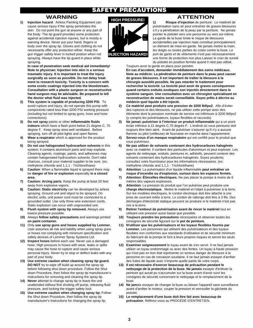
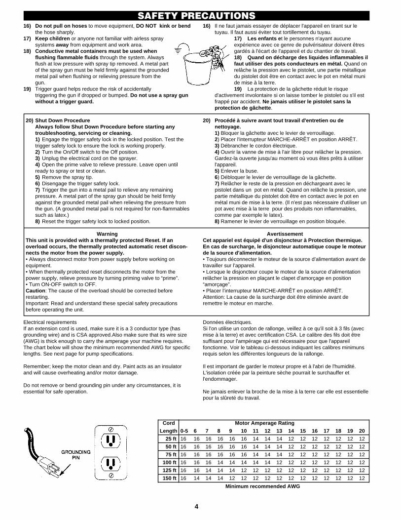
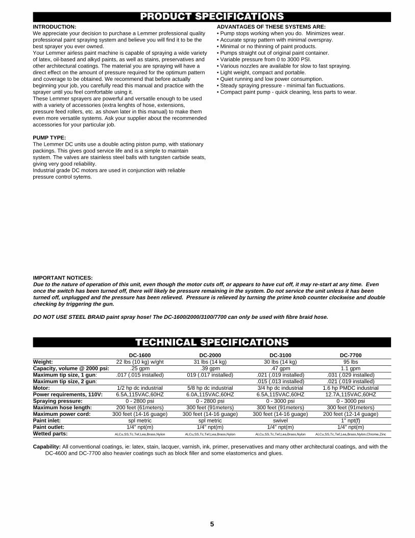


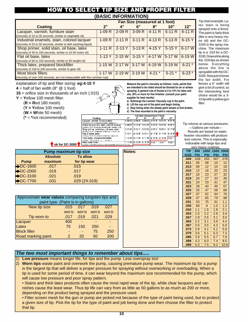
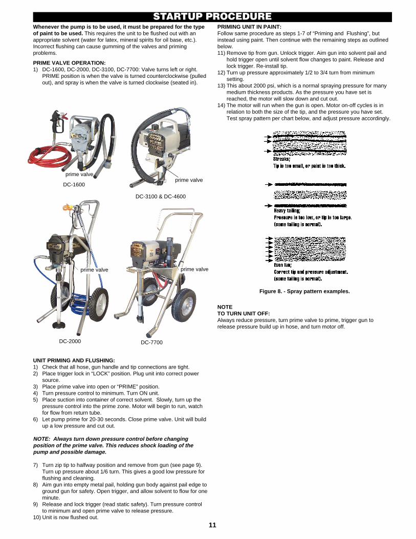


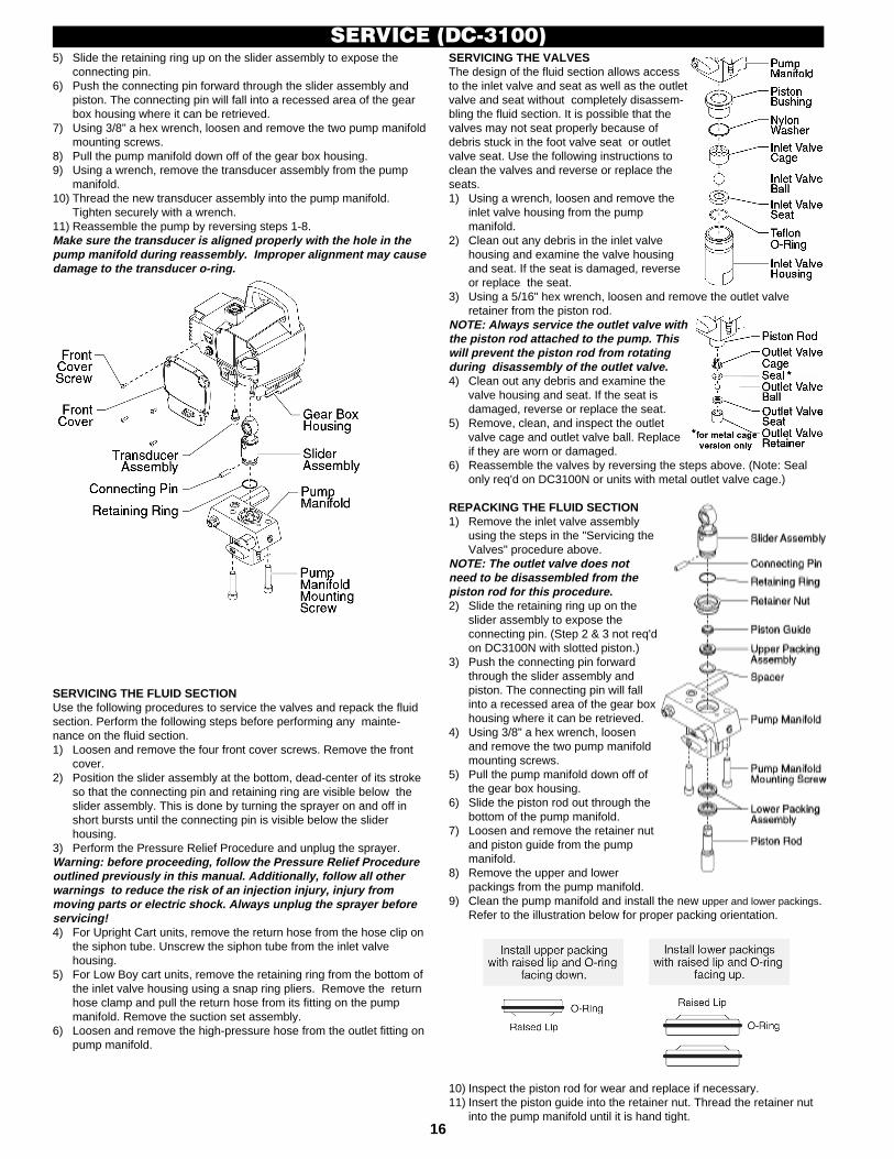
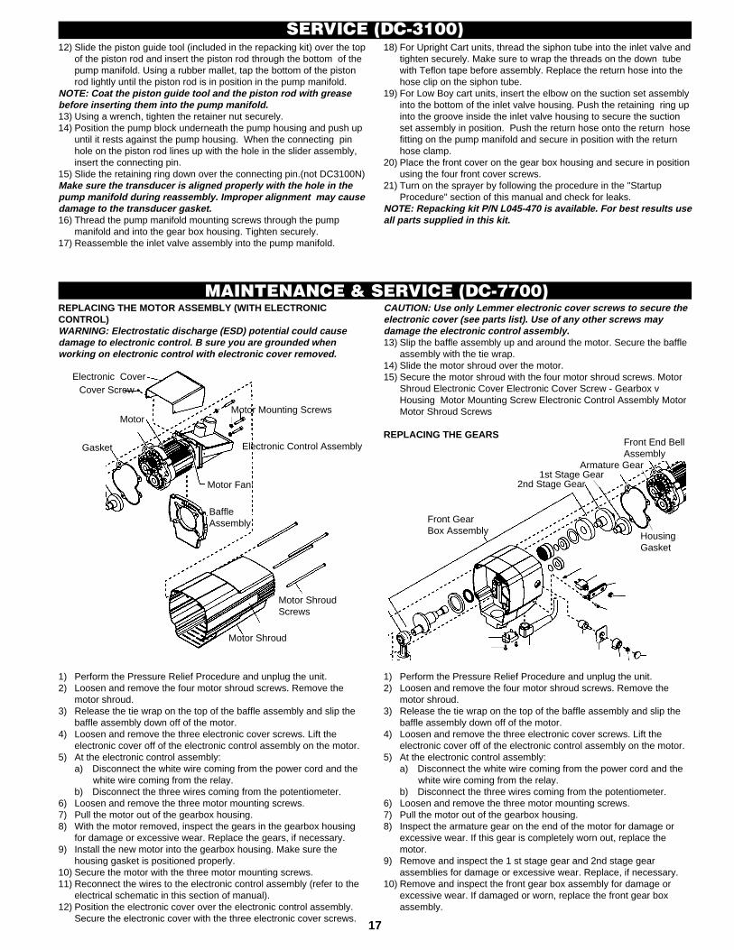


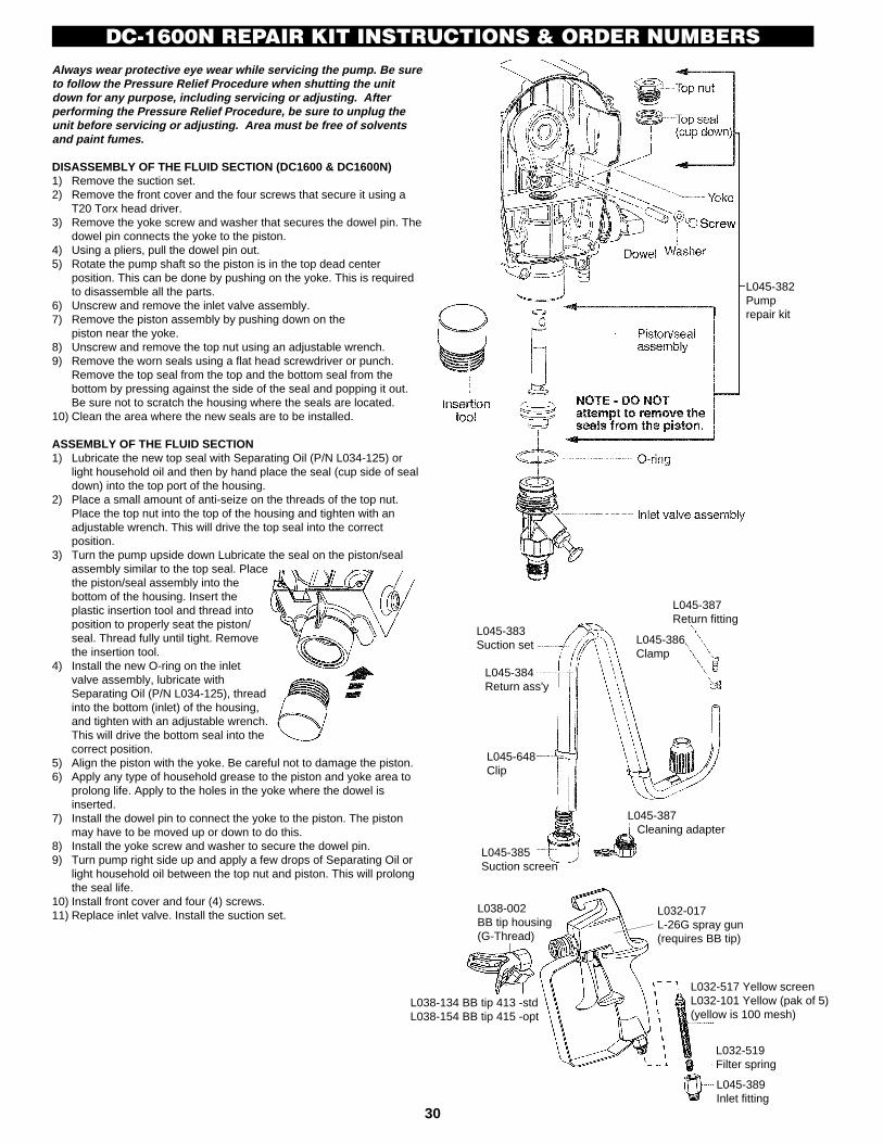

![DC2000 Security Target (Common Criteria) Security... · [18] THALES/ENG/DEV/STD/011 “VHDL Coding v1.0” [19] 0562b250, “Datacryptor 2000 Test Coverage Analysis” [20] 0562b251,](https://static.documents.pub/doc/80x56/5f849151ec5b007692307a92/dc2000-security-target-common-criteria-security-18-thalesengdevstd011.jpg)


