OWNER’S MANUAL
SAFETY INSTRUCTIONS
Please read and keep these instructions with the fan.
MODEL: VAF3000P
For use in Class I, Groups A, B, C and D; Class II,
Groups E, F and G; and Class III.
Purchase Date: ___________________ Serial No. ___________________
Dealer: ______________________________________
1.800.779.3267 • www.schaeferfan.com
©2013 Schaefer Ventilation Equipment. All rights reserved.
M-VAF3000P
REINSTALLATION PROCEDURES CONTINUED
Step Six: Stand unit on its base, once again with the motor shaft towards you. Use a 7/8" open end wrench to
tighten the 90" hose fittings onto the brass hex nipples previously installed onto the motor through the motor
housing. Be sure to coat threaded joints with Loctite #545 Pneumatic Seal or equivalent product to assure leak free
installation of air hose fitting. Attach hose to the fittings by pushing onto ferrule until they snap-lock into place. Tug
on hose gently. If hoses release, push more firmly into the ferrule until you hear it snap-lock into place.
NOTE: Orient the unit so the back of the motor is facing you. Reinstall the hoses into the proper motor fittings.
Step Seven: Test air connections by attaching the unit to air supply line. Inspect hose connections for leaks. If a
leak is found, repeat sealing instructions outlined in Step Six.
CAUTION: Never touch the spinning motor shaft – severe personal injury will result.
Step Eight: Lay unit down with the motor shaft facing up. Install fan blade with the flat part of the shaft aligned with
the flat guide on the fan hub. Place 3/8" flat washer on top of the fan hub before securing the nut on the shaft with a
9/16" open end wrench. Tighten until you see one thread exposed above the installed nylon nut. You may need to
hold the blade by wedging it to prevent rotation during this procedure.
CAUTION: Never operate the unit with the fan blade installed without first installing the safety grill.
Severe personal injury will result.
Step Nine: Install grill, duct ring and grounding stud ring to the front of the unit’s housing. Assemble bolt with flat
washer first, then the ground stud ring and finally the star washer. This bolt assembly is then threaded through the
grill and duct ring into the unit’s housing. Repeat steps to install grill, duct ring and grounding stud to the rear of the
unit’s housing. You should use a ¼" rachet and a 5.5 mm socket for this procedure.
NOTE: There are three bolts used to attach each grill and duct ring. The longest of the three bolts is used to attach
the grounding stud ring to the unit’s housing.
CAUTION: Be sure to reattach flat washer, grounding wire stud ring and star washer to ensure proper operation.
Step Ten: Connect completely reassembled fan to air supply line and perform a final inspection of the unit to ensure
proper operation.
Step Eleven: Ensure ground continuity with a multi meter. Test with one lead attached to the grounding stud located
on the coupler plate, and complete the circuit by touching the secondary lead to the following points while noting
meter response:
1. The rivet holding the right side of the safety label in place.
2. The upper left corner rivet holding serial plate in place.
3. Any coupler plate rivet.
4. The front and rear grills. Test one of the bolts not connected to the ground wire.
5. Back of motor (long probe will be required to make contact).
NOTE: Some resistance may be present when testing various points. The objective of this test is to ensure that all
wires removed are properly attached.
CAUTION: This unit is UL/CUL listed for use in hazardous locations. The grounding system links metal
components together. If you fail to properly reattach grounding stud rings, washers, star washers and
bolts, static electric build-up can result. The UL/CUL listing for this unit will also be null and void.
TABLE OF CONTENTS
Warranty Terms and Obligations. . . . . . . . . . . . . . . . . . . . . . 1
Introduction. . . . . . . . . . . . . . . . . . . . . . . . . . . . . . . . . 2
General Safety Information and Operation. . . . . . . . . . . . . . . . . 3
Exploded View of the VAF3000P. . . . . . . . . . . . . . . . . . . . . . 4
Parts List. . . . . . . . . . . . . . . . . . . . . . . . . . . . . . . . . . 5
Air Motor Precautions and Operating Specs. . . . . . . . . . . . . . . . 6
Trouble Shooting. . . . . . . . . . . . . . . . . . . . . . . . . . . . . . 7
Lubrication and Servicing the Air Motor. . . . . . . . . . . . . . . . . . . 8
REMOVAL PROCEDURES CONTINUED
Step Six: Flip unit over on its back and remove the front motor assembly bolts with a 7/16" socket.
Step Seven: Use a 9/16" deep socket to remove the remaining brass hex fittings from the motor.
Step Eight: Rotate the unit 180° onto its face. Remove the three rear motor assembly bolts with the 7/16"
socket. Fish out the rear motor end plate with an offset screw driver.
NOTE: A grounding wire is attached to the end plate bolt located between the two air motor fittings.
CAUTION: Be sure to note the location of all grounding wires, washers and star washers before
removing. Reattached assemblies to the same location from which they were removed in order to
safeguard proper ground continuity.
Step Nine: The motor is now detached from the mounting assembly. Carefully slip out of the housing for re-
pair. Tape over the air fitting holes to prevent debris from falling into the motor while it is out of the housing.
Step Ten: Decide if you want to ship the motor to the factory for repair, order a service kit or purchase a new
motor. Please contact Schaefer at the number listed on the front of this manual to obtain parts, secure a return
authorization or receive technical assistance.
REINSTALLING THE AIR MOTOR INTO THE VAF3000P HOUSING
Step One: Prepare motor for installation by removing the shipping plugs from the air motor ports. Lay the
VAF3000P face down on a firm work surface.
Step Two: Carefully position air motor into the housing assembly with the motor shafts though the front
mounting plate. Be sure to align the air fitting holes of the motor and housing so that the fittings can be
installed into the motor through the housing.
Step Three: Coat threaded joints with Loctite #545 Pneumatic Seal or equivalent product to ensure leak free
installation of air fittings. Install the two brass hex nipples into the air motor and tighten with a 9/16" deep
socket.
Step Four: Stand unit on base with front facing you. Attach motor to front housing plate with three 7/16" bolts
while maneuvering the motor into position from the rear. Tighten securely with a 7/16" socket.
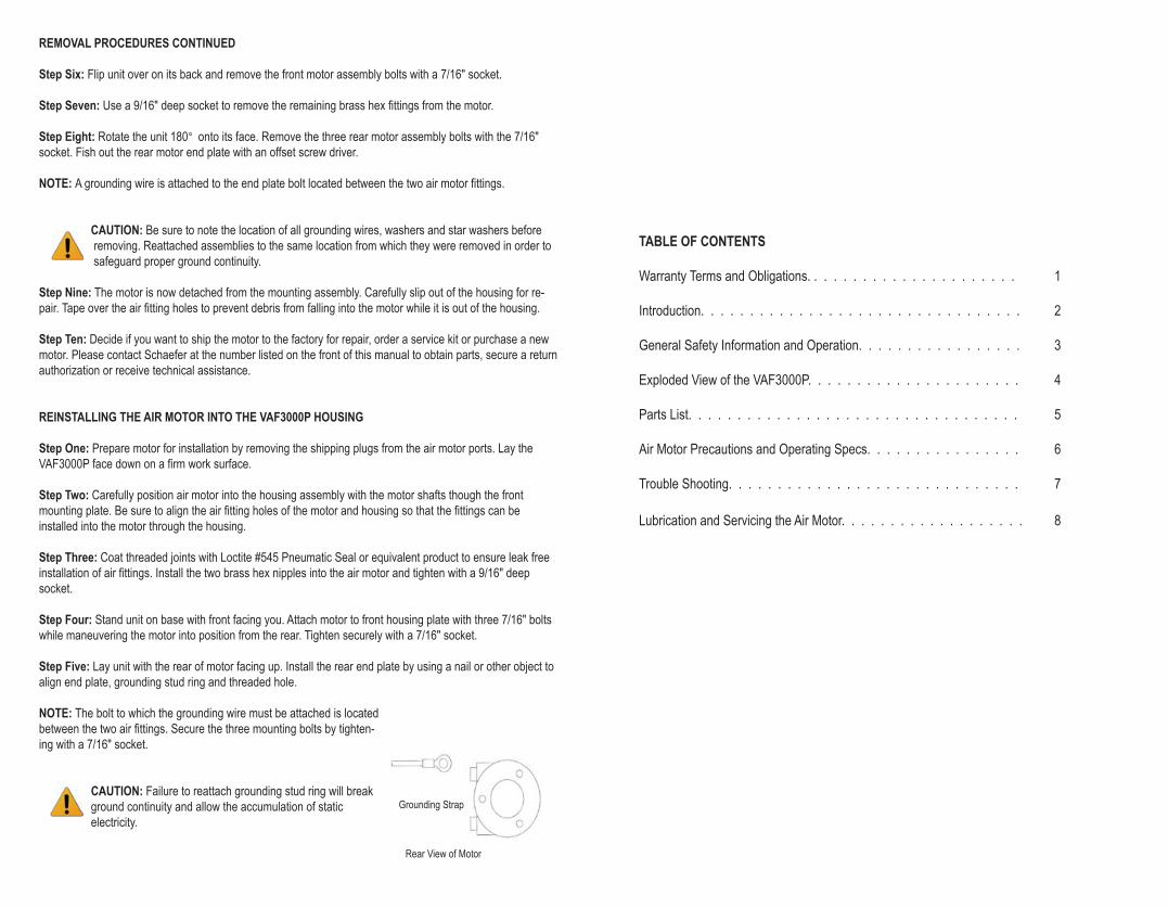
Step Five: Lay unit with the rear of motor facing up. Install the rear end plate by using a nail or other object to
align end plate, grounding stud ring and threaded hole.
NOTE: The bolt to which the grounding wire must be attached is located
between the two air fittings. Secure the three mounting bolts by tighten-
ing with a 7/16" socket.
CAUTION: Failure to reattach grounding stud ring will break
ground continuity and allow the accumulation of static
electricity.
Grounding Strap
Rear View of Motor
MOTOR REMOVAL & INSTALLATION TOOL LIST
Socket (7/16")
Deep Socket (9/16")
Open End Wrench (7/8")
Socket and Driver (5.5 mm)
Open End Wrench (3/4")
Loctite #545 or Pipe Seal
Duct tape for sealing motor ports
3 pieces of wood blocking cut to 12"
CAUTION: This unit is UL/CUL listed for use in hazardous locations. The grounding system links
all metal components together, If you fail to properly reattach grounding stud rings, washers, star
washers, and bolts, static electric build-up can result. The UL/CUL listing for this unit will also be
null and void.
MOTOR REMOVAL PROCEDURES
Step One: Remove Grills and Duct Rings from the front and rear of the unit. Use a ¼" ratchet and a 5.5 mm
socket to remove bolts, washers and star washers. Store these components in a safe place. They will be
needed for the reassembly of the unit.
Step Two: Position the unit so that the back of the motor is facing you. Disconnect air hoses one at a time
from the motor by pushing in on the ferrule lock ring while pulling on hoses. Label each hose with masking
tape and a pen. Mark the top line “Top Inlet”. Mark the bottom line “Bottom Exhaust”.
Step Three: Use a 7/8" open end wrench to spin off brass hex fittings from the air motor. NOTE: A ¾" open
end wrench may also be needed to spin off air connection ferrules of the 90° elbow because of limited space.
Step Four: Lay unit down with the fan blade facing up. Remove the nylock nut that holds the blade on shaft
with a 9/16" open end wrench and remove the 3/8" flat washer. You may need to wedge the fan blade to pre-
vent rotation during this procedure.
Step Five: Flip unit so that blade is facing workbench. Create a 3-legged
brace with pieces of wood cut approximately 12" in length. Pound gently on
the center of the cross beam to release the fan blade from the shaft.
NOTE: Even pressure is required on at least two points at the same time to
release the fan hub without causing damage to the blade assembly or motor
shaft.
CAUTION: Striking the back of the fan hub directly with a hard or sharp object (e.g. hammer or
screwdriver) may damage components.
Schaefer Limited Warranty Policy
Schaefer Ventilation Equipment, LLC (SVE) provides the following limited
warranty from the date of invoice to the initial purchaser of our products or
to its customer with a dated proof of purchase:
I. Two-year coverage applies to all products, components and assemblies
provided by SVE that prove to be defective in material or workmanship.
Any such defective product will be repaired or replaced at SVE’s
option, with the defective product or component returned, upon
approval, to SVE, F.O.B Sauk Rapids, Minnesota.
II. This warranty does not cover:
a. Failure, damage or malfunction as a result of:
i. Improper installation or installation not in accordance with
installation instructions.
ii. Operating conditions that vary from SVE’s operating
instructions.
iii. Misuse, abuse, negligence, alteration, or accident.
iv. Transporting the product.
v. Improper operation or lack of appropriate or regular
maintenance of the product.
b. Loss of time, inconvenience, loss of use of the product or
other consequential or incidental damages.
c. Parts that need replacement due to normal wear and tear.
d. Superficial or cosmetic rust or corrosion.
e. Any product whose name plate has been removed.
THERE ARE NO WARRANTIES OF MERCHANTABILITY OR FITNESS
OF USE.
Schaefer Ventilation reserves the right to change product design
and specification without prior notice or liability.
The above constitutes the sole warranty offered by Schaefer Ventilation
Equipment, LLC.
LUBRICATION
An automatic lubricator can be installed in the air line just ahead of the motor. The lubricator should be
adjusted to feed one drop of oil per minute. Lubrication is necessary for all internal moving parts and rust
prevention. Excessive moisture in the air line can cause rust formation in the motor and might also cause ice
to form in the muffler due to the expansion of air through the motor. The moisture problem can be corrected by
installing a moisture separator in the line and also by installing an after cooler between the compressor and air
receiver. USE DETERGENT SAE #10 AUTOMOTIVE ENGINE OIL.
SERVICING AIR MOTOR
If the motor is sluggish or inefficient, try flushing with recommended solvent. The recommended solvent for air
motors and lubricated pumps is Gast Flushing Solvent, Part #AH255 or AH255A, Demkote 2X726 Safety
Solvent, Inhibisol Safety Solvent or Dow Chemical Chlorothane.
To flush the unit, disconnect the air line from the coupler plate and remove the felt inside the muffler assembly.
Add several teaspoons of solvent directly into the air motor fitting. Rotate the fan shaft by hand in both
directions for a few minutes. Connect motor to an adjustable air supply. Slowly apply pressure until there is no
trace of solvent in exhausted air system. Reinstall the felt insert and secure the muffler cap.
CAUTION: Foreign material exiting the air motor can be hazardous. Solid or liquid material exiting
the unit can cause eye or skin damage. Keep away from air stream. Keep face away from exhaust
port. Eye protection is required.
CAUTION: Flush unit in a well-ventilated area only.
Re-lubricate the motor by squirting a drop of oil in the chamber. If the vanes need replacing or foreign
materials are present in motor chamber, an experienced mechanic may remove the end plate opposite the
drive shaft end. DO NOT PRY WITH A SCREWDRIVER.
It will dent the surface of the plate and body causing leaks. A puller tool should be used which will remove the
end plate while maintaining the position of the shaft. New vanes should have the edge with the corners cut on
an angle or the notched edge towards the bottom of the vane slot.
If motor requires service, it is highly recommended that the user remove the motor from the
housing as per the instructions provided in this manual and return it to the factory for repair.
A service kit is available; however, it should only be installed by a qualified mechanic. The
tolerances inside the air motor must be maintained to ensure top operating performance.
SHUTDOWN AND STORAGE PROCEDURE
1. Turn off air intake supply and remove plumbing.
2. Remove air motor from the connecting machinery.
3. Use clean, dry air at low pressure to ‘flush out’ condensates, such as water.
4. Re-lubricate the air motor with a squirt of oil in the chamber. Rotate the shaft by hand several times.
5. Plug or cap each port. The unit is now ready for storage.
INTRODUCTION
Congratulations on your selection of a new Vane Axial Fan from Schaefer Ventilation. Our goal is to provide you with
the very best in high performance air ventilators. Reading this Owner’s Manual will help you achieve the maximum
benefit from your portable air ventilator. If you do not understand any portion of this Manual, please contact
Schaefer, or your authorized Schaefer dealer for proper assistance prior to operating this Fan.
Do not allow anyone to operate the Vane Axial Fan without first reading the Operator’s Manual and becoming familiar
with its operation. Schaefer has endeavored to provide you with the finest equipment available for providing air for
portable ventilation purposes. The possibility does exist, however, that the Vane Axial Fan can be subjected to
applications not intended by Schaefer. Misuse and/or misapplication of the Vane Axial Fan can lead to the
possibility of serious damage, injury or even death. Anyone operating the Vane Axial Fan should refer to current
OSHA job safety and health rules and regulations pertaining to the construction industry, with a particular emphasis
on 29 CFR 1910, which contains rules governing Permit-Required Confined Spaces for General Industry.
Record the Vane Axial Fan model and serial number in the space provided below.
Model No.____________________________________Serial No.________________________________________
Date Purchased_______________________________________________________________________________
All specifications are general in nature and are not intended for specific application purposes. Schaefer accepts no
responsibility for variations which may be evident in actual products, specifications, pictures and descriptions
contained in this publication.
GENERAL TROUBLESHOOTING GUIDE
PROBLEM CAUSE SOLUTION
MOTOR TROUBLESHOOTING GUIDE
REASON LOW TORQUE LOW SPEED WON’T RUN RUNS HOT RUNS GOOD,
THEN SLOWS
Unit will not run
Unit runs but fan makes
loud scraping noise
Unit runs but vibrates
excessively
Unit runs but fan does
not turn
Unit runs but does not
develop full power
• No air supply to unit
• Faulty air supply line
• Connect air supply
• Perform maintenance and
check line to air supply
• Unit has been severely jolted
causing fan to rub against housing
• Unit has been severely jolted
causing housing to deform
• Remove motor and replace damaged motor mounts
• Perform maintenance and check line to air supply
• Severe jolt has bent motor shaft
causing unit to be out of balance
• Fan blade is damaged
• Dirt build-up on one side of fan blade
• Remove and replace motor
Replace fan blade as necessary
• Replace fan blade
• Clean fan blade
• Fan is jammed
• Housing has been damaged and presses on the fan blade
• Low air supply pressure
• Low air supply cfm
• Excessive duct length
• Worn motor vanes
• Remove motor and replace damaged
motor mounts
• Replace fan blade if necessary
• Replace housing/unit as necessary
• Supply 100 psi air
• Increase size of compressor
and/or size of supply lines to provide at least 71 cfm
• Reduce duct length to recommended maximum
• Rebuild motor
Dirt, Foreign Material
Internal Rust
Misalignment
Insufficient Air Pressure
Too Small Air Line
Restricted Exhaust
Poor Lubrication
Jammed Machine
Compressor Too Small
Compressor Too Far
From Unit
X
X
X
X
X
X
X
X
X
X
X
X
X
X
X
X
X
X
X
X
X
X
X
X
X
X
X
SAFETY SYMBOL
When you see this symbol, CAUTION, be aware that personal injury or property damage is possible. The hazard
is explained in the text following the symbol.
CAUTION: Severe personal injury or death COULD occur if hazard is ignored.
AIR MOTOR PRECAUTIONS
CAUTION: The air motor is designed to be driven by compressed air. Under no circumstances should the air
motor be driven by any other gases. The air motor must not be driven by fluids, particles, solids or any
substance mixed with air, particularly combustible substances likely to cause explosions.
CAUTION: DO NOT USE KEROSENE OR OTHER COMBUSTIBLE SOLVENTS.
CAUTION: Foreign materials exiting the air motor can be hazardous. Solid or liquid materials exiting the unit
can cause eye or skin damage. Keep away from air stream.
CAUTION: Keep face away from exhaust port. Eye protection is required.
CAUTION: Water, vapor, oil-based contaminates or other liquids must be filtered out.
CAUTION: Do not drive the air motor in excess of the recommended operating maximums below. Ambient
temperature should not exceed 121°C (250°F).
INTERNAL OPERATING MAXIMUMS
Motor Size Maximum RPM Maximum Pressure Maximum Torque Maximum Air
(psi) in lb. – inch Consumption in cfm
V4 3000 100 36.29 38
CAUTION: Do not allow the air motor to ‘run free’ at high speeds without a load. Excessive internal heat
buildup will result in loss of internal clearance and rapid motor damage.
CFM RATINGS
Free Air 2063 cfm 25' 1-90° Bend 1497 cfm
15' Straight Duct 1753 cfm 25' 2-90° Bend 1433 cfm
15' 1-90° Bend 1616 cfm 100’ Straight Blowing 1243 cfm
25' Straight Duct 1619 cfm
CAUTION: Always disconnect the unit from the air supply before servicing.
GENERAL SAFETY INFORMATION
These instructions are for your protection and convenience. Please read them carefully since failure to follow these
precautions could result in injury or even death.
• Always use the VAF3000P in accordance with the required operation standards listed below.
• Never put the VAF3000P into standing water or allow water inside the motor.
• Never store the VAF3000P outdoors.
• Never allow the air intake screens to become plugged.
• Never put any object in the intake screen unless the unit is disconnected from the air supply line and the fan blade
has stopped turning.
• Do not allow the unit to be used as a toy. Close attention is necessary when used by or near children.
• Keep hair, loose clothing, fingers and all parts of the body away from the intake screen. If the fan is not working
properly because it has been dropped, damaged, left outdoors or submerged in water, contact Schaefer at
(320) 251-8696.
INSTRUCTIONS FOR OPERATION AND CARE
OPERATION STANDARDS
FOR ALL APPLICATIONS FOR HAZARDOUS LOCATIONS
• 100 psi maximum • CAUTION: Ground unit at lug on coupler plate
• Clean, dry, lubricated air supply required • Air supply lines shall be made of electrically
conductive material in accordance with the
recommended practice on static electricity, NFPA 11,
and/or any other applicable local code
• Your new VAF3000P comes to you completely assembled and ready to operate. Carefully inspect unit for any
possible damage from transit.
• When using the VAF3000P, note the directional airflow indicator on the external shell. This is the way the air moves.
• Prior to connecting the VAF3000P to the air supply line, inspect the inlet and outlet screen and remove any debris that
may restrict airflow movement.
WHEN USED WITH DUCTING FOR HAZARDOUS LOCATIONS
• Do not install duct when fan is in operation • Use only ‘Static Conductive Hose’ properly grounded.
If connecting duct to duct, use only ‘Static Conductive’
couplers made of aluminum
• Place duct lip over duct adapter and secure firmly
• Note the direction of the airflow as indicated by the
arrow on the side of the fan
SPECIFICATIONS DIMENSIONS
Pneumatic Motor: 1.5 hp Height: 21" 53.34 cm
RPM: 3000 Width: 14" 35.65 cm
CFM: 2063 Length: 17" 43.18 cm
Duct Adapter: 12" 30.48 cm
Weight: 28 lbs. 12.75 kg.
VAF3000P PICTORIAL BREAKDOWN VAF3000P Parts List