Owner’s Operation and Instruction Manual C S S U C O M P A N Y U N I T E D S T A T E S S T O V E SAFETY NOTICE: If this heater is not properly installed, a house fire may result. For your safety, follow the in- stallation instructions. Never use make-shift compromises during the installation of this heater. Contact local building or fire officials about permits, restrictions and installation requirements in your area. CAUTION! Please read this entire manual before you install or use your new room heater. Failure to follow instructions may result in property damage, bodily injury, or even death. Improper Installation Could Void Your Warranty! SAFETY TESTED TO UL 1482 and ULC-S627 US ENVIRONMENTAL PROTECTION AGENCY PHASE II CERTIFIED WOODSTOVE WASHINGTON STATE APPROVED MOBILE HOME APPROVED (U.S. ONLY) United States Stove Company 227 Industrial Park Road P.O. Box 151 South Pittsburg, TN 37380 SAVE THESE INSTRUCTIONS THIS MANUAL WILL HELP YOU TO OBTAIN EFFICIENT, DEPENDABLE SERVICE FROM THE HEATER, AND ENABLE YOU TO ORDER REPAIR PARTS CORRECTLY. KEEP IN A SAFE PLACE FOR FUTURE REFERENCE. 851710 rev E MODELS: 2000(L)(LN), 2500(L)(LN) 2000 Report #: 215-S-29-2 2500 Report #: 215-S-23-2 TESTED & LISTED BY PORTLAND, OREGON, USA French version is available for download from the U. S. Stove website: http://www.usstove.com/
Transcript
Owner’s Operation and Instruction Manual
CSSUCOMPANY
UNITED STATES STOVE
SAFETY NOTICE:If this heater is not properly installed, a house fire may result. For your safety, follow the in-stallation instructions. Never use make-shift compromises during the installation of this heater. Contact local building or fire officials about permits, restrictions and installation requirements in your area.
CAUTION!Please read this entire manual before you install or use your new room heater. Failure to follow instructions may result in property
damage, bodily injury, or even death.
Improper Installation Could VoidYour Warranty!
SAFETY TESTED TO UL 1482 and ULC-S627
US ENVIRONMENTAL PROTECTION AGENCY PHASE II CERTIFIED WOODSTOVE
WASHINGTON STATE APPROVED
MOBILE HOME APPROVED (U.S. ONLY)
United States Stove Company227 Industrial Park Road
P.O. Box 151South Pittsburg, TN 37380
SAVE THESE INSTRUCTIONSTHIS MANUAL WILL HELP YOU TO OBTAIN EFFICIENT, DEPENDABLE SERVICE FROM THE HEATER, AND ENABLE YOU
TO ORDER REPAIR PARTS CORRECTLY. KEEP IN A SAFE PLACE FOR FUTURE REFERENCE.
French version is available for download from the U. S. Stove website: http://www.usstove.com/
2 Ussc
OPTIONAL ACCESSORIESDESCRIPTION PART #Outside Air Intake Kit 50FAK
CONGRATULATIONS!You’ve purchased a heater from North America’s oldest manufacturer of wood burning products.
By heating with wood you’re helping to CONSERVE ENERGY!
Wood is our only Renewable Energy Resource. Please do your part to preserve our wood supply. Plant at least one tree each year. Future generations will thank you.
The instructions pertaining to the installation of your wood stove comply with UL-1482 and ULC-S627 standards.
CAUTIONS:
• HOTWHILEINOPERATION.KEEPCHILDREN,CLOTHINGANDFURNITUREAWAY.CONTACT MAY CAUSE SKIN BURNS.
What was the determining factor for purchasing your new appliance?_______
I have read the owner’s manual that accompanies this unit and fully understand the:Installation q Operation q and Maintenance q of my new appliance.
Print Name Signature Date
Please attach a copy of your purchase receipt.
Warranty not valid without a Proof of Purchase.
Warranty information must be received within 30 days of original purchase.
Detach this page from this manual, fold in half with this page to the inside and tape together. Apply a stamp and mail to the address provided. You may use an enve-lope if you choose.
You may register online by going to www.usstove.com
All information submitted will be kept strictly confidential. Information provided will not be sold for advertising purposes.Contact information will be used solely for the purpose of product notifications.
4 Ussc
"
CU
T H
ER
E"
CU
T H
ER
E
Ê ÉFold Here Fold Here
United States Stove CompanyP.O. Box 151South Pittsburg, TN 37380
Fold Here
PlACESTAMPHERE
Ussc 5
Tools and Materials Needed For InstallationYou will need a drill with a 1/8” bit to install sheet metal screws into connector pipe. A 5/16” socket/wrench or screw driver toinstallpedestaltrim,roomairdeflector,andblowerassemblydescribedbelow.A1/2”socket/wrenchtoinstallfluecollar.Anon-combustiblefloorprotectorasspecifiedinthismanual.Allchimneyandchimneyconnectorcomponentsrequired for your particular chimney installation. For mobile homes, see page 13.
AssemblyFlue Collar Assembly:1. Mountthefluecollartothetopoftheunitasshownusingthe(3)5/16-18 x 1-1/2 bolts, (3) washers, and (3) weld tabs provided in the parts box.
Room Air Deflector Assembly:1. LocatetheRoomAirDeflector.Usingthethree(3)1/2TekScrewsprovided,mountthedeflectortotheunitas shown in the diagram.
Firebrick Configuration:1. Replace the Firebrick as shown in the illustration below.
Side view of flue collarmount to heater top
Brick Configuration
HEATERTOP
WELD TAB
5/16-18 x 1-1/2 BOLT
2000 2500
6 Ussc
ASSEMBLY INSTRUCTIONSBlower AssemblyTHE BLOWER ASSEMBLY MUST BE DISCONNECTED FROM THE SOURCE OF ELECTRICAL SUPPLY BEFORE ATTEMPTING THE INSTALLATION.THE BLOWER ASSEMBLY IS INTENDED FOR USE ONLY WITH A STOVE THAT IS MARKED TO INDICATE SUCH USE.
DO NOT ROUTE THE SUPPLY CORD NEAR OR ACROSS HOT SURFACES!
Step 1.Fix the assembly to the back of the stove with the four screws provided.
Pedestal Trim AssemblyAssemble trim pieces as shown with the screws provided in the parts bag. Washers may not be necessary.
After trim assembly, attach to the pedestal base at the location shown using the screws provided.
Ash Pan AssemblyRemove ash pan from firebox. Under the firebox, there are two brackets; Slide the ash pan into these brackets.
Ussc 7
INSTALLATION
SAFETY NOTICE
• IF THISSTOVE ISNOTPROPERLY INSTALLED,AHOUSEFIREMAYRESULT. TOREDUCETHERISKOFFIRE,FOLLOWTHEINSTALLATIONINSTRUCTIONS.
• CONSULTYOURMUNICIPALBUILDINGDEPARTMENTORFIREOFFICIALSABOUTPERMITS, RESTRICTIONS AND INSTALLATIONS REQUIREMENTS IN YOUR AREA.
It is very important to position the wood stove as close as possible to the chimney, and in an area thatwillfavorthemostefficientheatdistributionpossiblethroughoutthehouse.Thestovemusttherefore be installed in the room where the most time is spent, and in the most spacious room possible. Recall that wood stoves produce radiating heat, the heat we feel when we are close to a wood stove. A wood stove also functions by convection, that is through the displacement of hot air accelerated upwards and its replacement with cooler air. If necessary, the hot air distribution from the stove may be facilitated by the installation of a blower.
The wood stove must not be hooked up to a hot air distribution system since an excessive accumulation of heat may occur.A wood stove must never be installed in a hallway or near a staircase, since it may block the way in case of fire or fail to respect required clearances.
8 Ussc
FLOOR PROTECTORYour wood stove should be placed on a 1 inch, non-combustible surface with a k factor of 0.84. For multiple layers, add R-values of each layer to determine the overall R-value. The R value for the requiredboardis1.2.Ifthereisahorizontalsectionofchimneyconnector,thefloorprotectorshouldgo under it and 2 inches beyond each side
ConvertspecificationtoR-value: k-factor is given with a required thickness (T) in inches: R=1/k x T C-factor is given: R=1/C
Example: If thefloorprotector is4”brickwithaC-factorof1.25over1/8”mineralboardwitha “k”factor of 0.29 the total R-value of the system is: 4” brick C=1.25, R=1/1.25=0.8 1/8” mineral board K=0.29, R=1/0.29 x 0.125=0.431 Total R = Rbrick + Rmineral = 0.8 + 0.431 = 1.231 Total R is greater than 1.2, the system is acceptable.
Thefloorprotectorshouldexceedthestoveasfollows:
Model Front Sides Rear2000 25”
(635mm)8”
(203mm)¶6”
(152mm)2500 26”
(660mm)8”
(203mm)¶6”
(152mm)
¶ - Canadian installations require 8” (203mm)
Ussc 9
CLEARANCES TO COMBUSTIBLESIt is of utmost importance that the clearances to combustible materials be strictly adhered to during installation of the stove. Refer to the tables below :
Single Wall Pipe (Double Wall Pipe)Model A B C D E F2000 20(14)
(508mm(356mm))22(20)
(559mm(508mm))22.5(16.5)
(572mm(419mm))32(30)
(813mm(762mm))12(11)
(305mm(279mm))22(21)
(559mm(533mm))
2500 12(305mm)
20(508mm)
16(406mm)
30(762mm)
10.5(267mm)
20(508mm)
10 Ussc
CHIMNEY CONNECTOR (STOVE PIPE)Your chimney connector and chimney must have the same diameter as the stove outlet (6”). If this is not the case, we recommend you contact your dealer in order to insure there will be no problem with the draft.
The stove pipe must be made of aluminized or cold roll steel with a minimum thickness of 0.021” or 0.53 mm. It is strictly forbidden to use galvanized steel.
Your smoke pipe should be assembled in such a way that the male section (crimped end) of the pipe faces down. Attach each of the sections to one another with three equidistant metal screws.
The pipe must be short and straight. All sections installed horizontally must slope at least 1/4 inch per foot, with the upper end of the section toward the chimney. Any installation with a horizontal run of chimney pipe must conform to NFPA 211. You may contact NFPA (National Fire Protection Association) and request the latest edition of the NFPA Standard 211.
To insure a good draft, the total length of the coupling pipe should never exceed 8’ to 10’ (2.4m to 3.04 m). (Except for cases of vertical installation, cathedral-roof style where the smoke exhaust system can be much longer and connected without problem to the chimney at the ceiling of the room).
There should never be more than two 90 degrees elbows in the smoke exhaust system.
Installation of a “barometric draft stabilizer” (fireplace register) on a smoke exhaust system isprohibited.
Furthermore, installation of a draft damper is not recommended. Indeed, with a controlled combustion wood stove, the draft is regulated upon intake of the combustion air in the stove and not at the exhaust.
Ussc 11
CHIMNEYYour wood stove may be hooked up with a 6” factory built or masonry chimney. If you are using a fac-torybuiltchimney,itmustcomplywithUL103orCSA-B365standard;thereforeitmustbeaTypeHT(2100°F).Itisextremelyimportantthatitbeinstalledaccordingtothemanufacturer’sspecifications.
Theinteriordiameterofthechimneyfluemustbeidenticaltothestovesmokeexhaust.Afluewhichistoosmallmaycausedraftproblems,whilealargefluefavoursrapidcoolingofthegas,andhencethebuild-upofcreosoteandtheriskofchimneyfires.Notethatitisthechimneyandnotthestovewhich creates the draft effect; your stove’s performance is directly dependent on an adequate draft from your chimney.
The following recommendations may be useful for the installation of your chimney:1. DO NOT CONNECT THIS UNIT TO A CHIMNEY FLUE SERVING ANOTHER APPLIANCE.2. It must rise above the roof at least 3’ (0.9m) from the uppermost point of contact.3. The chimney must exceed any part of the building or other obstruction within a 10’ (3.04m)
distance by a height of 2’ (0.6m).4. Installation of an interior chimney is always preferable to an exterior chimney. Indeed, the
interior chimney will, by definition, be hotter than an exterior chimney, being heated up by the ambient air in the house. Therefore the gas which circulates will cool more slowly, thus reducing the build-up of creosote and the risk of chimney fires.
5. The draft caused by the tendency for hot air to rise will be increased with an interior chim-ney.
6. Using a fire screen at the extremity of the chimney requires regular inspection in order to insure that it is not obstructed thus blocking the draft, and it should be cleaned when used regularly.
12 Ussc
FACTORY BUILT CHIMNEY :When a metal prefabricated chimney is used, the manufacturer’s installation instructions must be followed. You must also purchase (from the same manufacturer) and install the ceiling support packageorwallpass-throughand“T”sectionpackage,firestops(whereneeded),insulationshield,roofflashing,chimneycap,etc.Maintainproperclearancetothestructureasrecommendedbythemanufacturer. The chimney must be the required height above the roof or other obstructions for safety and proper draft operation.
Ussc 13
MASONRY CHIMNEY :Ensure that a masonry chimney meets the minimum standards of the National Fire Protection As-sociation (NFPA) by having it inspected by a professional. Make sure there are no cracks, loose mortarorothersignsofdeteriorationandblockage.Havethechimneycleanedbeforethestoveisinstalled and operated. When connecting the stove through a combustible wall to a masonry chim-ney, special methods are needed.
14 Ussc
Combustible Wall Chimney Connector Pass-Throughs
Method A. 12” (304.8 mm) Clearance to Combustible Wall Mem-ber: Using a minimum thickness 3.5” (89 mm) brick and a 5/8” (15.9 mm) minimum wall thickness clay liner, construct a wall pass-through. The clay liner must conform to ASTM C315 (Standard SpecificationforClayFireLinings)oritsequivalent.Keepamini-mum of 12” (304.8 mm) of brick masonry between the clay liner and wall combustibles. The clay liner shall run from the brick masonry outersurfacetotheinnersurfaceofthechimneyfluelinerbutnotpast the inner surface. Firmly grout or cement the clay liner in place tothechimneyflueliner.
Method B. 9” (228.6 mm) Clearance to Combustible Wall Member: Using a 6” (152.4 mm) inside diameter, listed, factory-built Solid-Pak chimney section with insulation of 1” (25.4 mm) or more, build a wall pass-through with a minimum 9” (228.6 mm) air space be-tween the outer wall of the chimney length and wall combustibles. Use sheet metal supports fastened securely to wall surfaces on all sides, to maintain the 9” (228.6 mm) air space. When fastening supports to chimney length, do not penetrate the chimney liner (the inside wall of the Solid-Pak chimney). The inner end of the Solid-Pakchimneysectionshallbeflushwiththeinsideofthemasonrychimneyflue,andsealedwithanon-watersoluble refractoryce-ment. Use this cement to also seal to the brick masonry penetra-tion.
Method C. 6” (152.4 mm) Clearance to Combustible Wall Member: Starting with a minimum 24 gage (.024” [.61 mm]) 6” (152.4 mm) metal chimney connector, and a minimum 24 gage ventilated wall thimble which has two air channels of 1” (25.4 mm) each, construct a wall pass-through. There shall be a minimum 6” (152.4) mm sep-arationareacontainingfiberglassinsulation,fromtheoutersurfaceof the wall thimble to wall combustibles. Support the wall thimble, and cover its opening with a 24-gage minimum sheet metal sup-port. Maintain the 6” (152.4 mm) space. There should also be a supportsizedtofitandholdthemetalchimneyconnector.Seethatthe supports are fastened securely to wall surfaces on all sides. Make sure fasteners used to secure the metal chimney connector donotpenetratechimneyflueliner.
Method D. 2” (50.8 mm) Clearance to Combustible Wall Mem-ber: Start with a solid-pak listed factory built chimney section at least 12” (304 mm) long, with insulation of 1” (25.4 mm) or more, and an inside diameter of 8” (2 inches [51 mm] larger than the 6” [152.4 mm] chimney connector). Use this as a pass-through for a minimum 24-gauge single wall steel chimney connector. Keep solid-pak section concentric with and spaced 1” (25.4 mm) off the chimney connector by way of sheet metal support plates at both ends of chimney section. Cover opening with and support chimney section on both sides with 24 gage minimum sheet metal supports. See that the supports are fastened securely to wall surfaces on all sides.Makesurefastenersusedtosecurechimneyflueline.
NOTES:1. Connectors to a masonry chimney, excepting method B, shall extend in one continuous section throughthewallpass-throughsystemandthechimneywall,tobutnotpasttheinnerfluelinerface.2. A chimney connector shall not pass through an attic or roof space, closet or similar concealed space,orafloor,orceiling.
Ussc 15
OUTSIDE COMBUSTION AIRYour wood stove is approved to be installed with an outside air intake which is necessary for a mobile home. This type of installation is also required in air tight houses and houses with negative pressure problems. You can purchase this option through your heater dealer. Make sure to specify the part number mentioned in this booklet. Installation instructions are supplied with the air intake kit.
Outside combustion air may be required if :
1. Your stove does not draw steadily, smoke rollout occurs, wood burns poorly, or back-drafts occur whether or not there is combustion present.
2.Existingfuel-firedequipmentinthehouse,suchasfireplacesorotherheatingappliances,smell,do not operate properly, suffer smoke roll-out when opened, or back-drafts occur whether or not there is combustion present.
3. Opening a window slightly on a calm (windless) day alleviates any of the above symptoms.
4.Thehouseisequippedwithawell-sealedvaporbarrierandtightfittingwindowsand/orhasanypowered devices that exhaust house air.
5. There is excessive condensation on windows in the winter.
6. A ventilation system is installed in the house.
For use in MOBILE HOMES (U. S. installations ONLY):
• WARNING! DO NOT INSTALL IN SLEEPING ROOM.• CAUTION! THE STRUCTURAL INTEGRITY OF THE MOBILE HOME FLOOR, WALL, AND
CEILING/ROOF MUST BE MAINTAINED.• INSTALLINACCORDANCEWITH24CFR,PART3280(HUD).
WOODSTOVE UTILIZATIONYourheatingunitwasdesignedtoburnwoodonly;noothermaterialsshouldbeburned.Wasteandotherflammablematerialsshouldnotbeburnedinyourstove.Anytypeofwoodmaybeusedinyourstove,butspecificvarietieshavebetter energy yields than others. Please consult the following table in order to make the best possible choice.
It is EXTREMELY IMPORTANT that you use DRY WOOD only in your wood stove. The wood should have dried for 9 to 15 months, such that the humidity content (in weight) is reduced below 20% of the weight of the log. It is very important to keep in mind that even if the wood has been cut for one, two or even more years, it is not necessarily dry, if it has been stored in poor conditions. Under extreme conditions it may rot instead of drying. This point cannot be over stressed; the vast majority of the problems related to the operation of a wood stove is caused by the fact that the wood used was too damp or had dried in poor conditions. These problems can be:
Smaller pieces of wood will dry faster. All logs exceeding 6” in diameter should be split. The wood should not be stored directly on the ground. Air should circulate through the cord. A 24” to 48” air space should be left between each row of logs, which should be placed in the sunniest location possible. The upper layer of wood should be protected from the elements but not the sides.
TESTING YOUR WOODWhenthestoveisthoroughlywarmed,placeonepieceofsplitwood(aboutfiveinchesindiameter)paralleltothedooron the bed of red embers.
Keep the air control full open by pulling on it and close the door. If ignition of the piece is accomplished within 90 seconds from the time if was placed in the stove, your wood is correctly dried. If ignition takes longer, your wood is damp.
If your wood hisses and water or vapor escapes at the ends of the piece, your wood is soaked or freshly cut. Do not use this wood in your stove. Large amounts of creosote could be deposited in your chimney, creating potential conditions forachimneyfire.
Ussc 17
THE FIRST FIRESThe fresh paint on your stove needs to be cured to preserve its quality. Once the fuel charge is properly ignited, only burnsmallfiresinyourstoveforthefirstfourhoursofoperation.Neveropentheaircontrolmorethannecessarytoachieve a medium burn rate.
IGNITIONAfter making sure that the stove air intake controls are fully open (completely pull-out towards you), place several rumpled sheets of paper in the centre of the combustion chamber. Place 8 to 10 pieces of small dry kindling wood over the paper in the form of a tent. You may also place a few pieces of heating wood, but choose the smaller ones. No chemical product shouldbeusedtolightthefire.
Before igniting the paper and kindling wood, it is recommended that you warm up the chimney. This is done in order to avoid back draft problems often due to negative pressure in the house. If such is the case, open a window slightly near the stove and twist together a few sheets of newspaper into a torch. Light up this paper torch and hold it as close as possible to the mouth of the pipe inside the combustion chamber to warm up the chimney. Once the updraft movement is initiated, you are ready to ignite the stove by lighting the paper and kindling wood inside the combustion chamber.
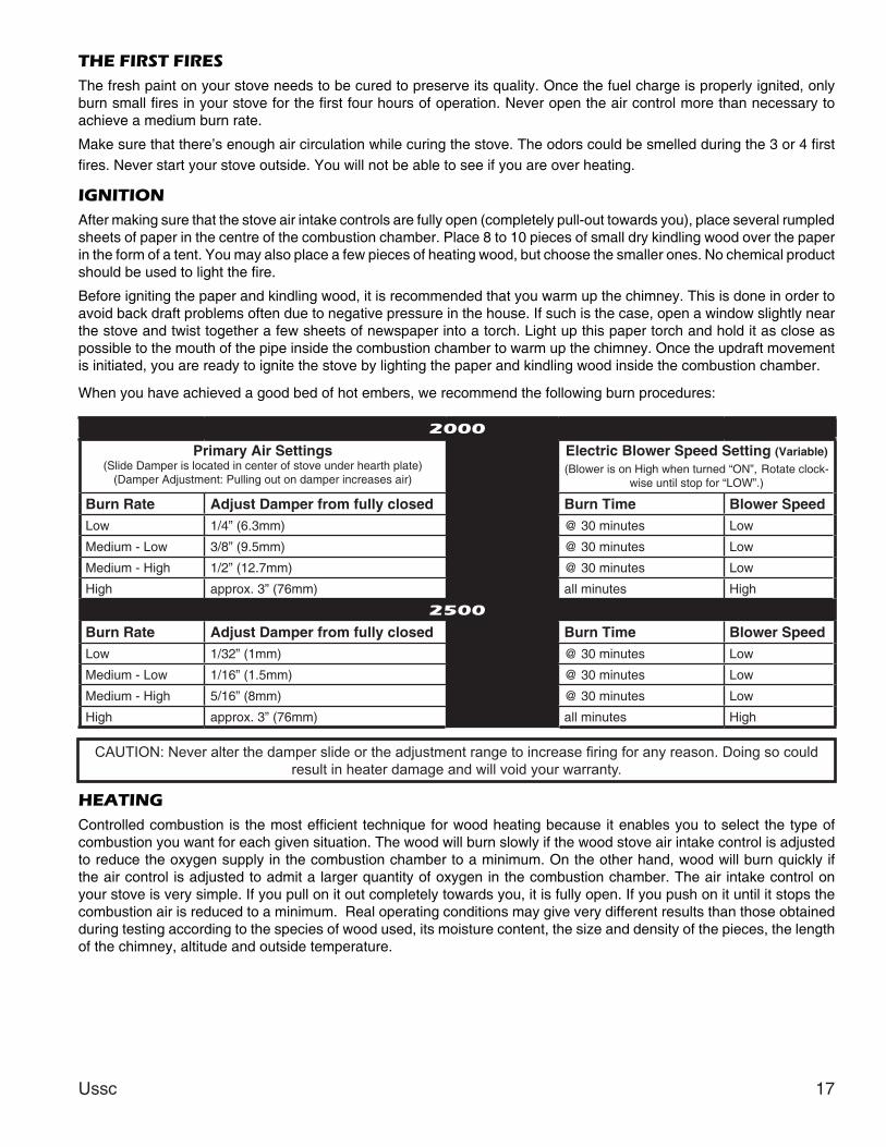
When you have achieved a good bed of hot embers, we recommend the following burn procedures:
HEATINGControlledcombustion is themostefficient techniqueforwoodheatingbecauseitenablesyoutoselect thetypeofcombustion you want for each given situation. The wood will burn slowly if the wood stove air intake control is adjusted to reduce the oxygen supply in the combustion chamber to a minimum. On the other hand, wood will burn quickly if the air control is adjusted to admit a larger quantity of oxygen in the combustion chamber. The air intake control on your stove is very simple. If you pull on it out completely towards you, it is fully open. If you push on it until it stops the combustion air is reduced to a minimum. Real operating conditions may give very different results than those obtained during testing according to the species of wood used, its moisture content, the size and density of the pieces, the length of the chimney, altitude and outside temperature.
2000
Primary Air Settings(Slide Damper is located in center of stove under hearth plate)
(Damper Adjustment: Pulling out on damper increases air)
Electric Blower Speed Setting (Variable)(BlowerisonHighwhenturned“ON”, Rotate clock-
wiseuntilstopfor“LOW”.)
Burn Rate Adjust Damper from fully closed Burn Time Blower SpeedLow 1/4” (6.3mm) @ 30 minutes Low
Medium - Low 3/8” (9.5mm) @ 30 minutes Low
Medium-High 1/2” (12.7mm) @ 30 minutes Low
High approx. 3” (76mm) all minutes High
2500
Burn Rate Adjust Damper from fully closed Burn Time Blower SpeedLow 1/32” (1mm) @ 30 minutes Low
Medium - Low 1/16” (1.5mm) @ 30 minutes Low
Medium-High 5/16” (8mm) @ 30 minutes Low
High approx. 3” (76mm) all minutes High
CAUTION: Never alter the damper slide or the adjustment range to increase firing for any reason. Doing so could result in heater damage and will void your warranty.
Once you have obtained a good bed of embers, you should reload the unit. In order to do so, open the air controls to maximum a few seconds prior to opening the stove’s door. Then proceed by opening the door very slowly; open it one or two inches for 5 to 10 seconds, before opening it completely to increase the draft and thus eliminate the smoke which is stagnant in a state of slow combustion in the stove. Then bring the red embers to the front of the stove and reload the unit.
For optimal operation of your wood stove, we recommend you to operate it with a wood load approximatelyequivalenttotheheightoffirebricks.
It is important to note that wood combustion consumes ambient oxygen in the room .In the case of negative pressure, it is a good idea to allow fresh air in the room, either by opening a window slightly or by installing a fresh air intake system on an outside wall.
Creosote - Formation and Need for Removal - When wood is burned slowly, it produces tar and other organic vapors, which combine with expelled moisture to form creosote. The creosote vapors condense intherelativelycoolchimneyflueofaslow-burningfire.Asaresult,creosoteresidueaccumulatesonthefluelining.Whenignitedthiscreosotemakesanextremelyhotfire.Thechimneyconnector and chimney should be inspected at least once every two months during the heating season to determine if a creosote build-up has occurred. If creosote has accumulated (3mm or more), it shouldberemovedtoreducetheriskofachimneyfire.
We strongly recommend that you install a magnetic thermometer on your smoke exhaust pipe, approximately 18” above the stove. This thermometer will indicate the temperature of your gas exhaust fumes within the smoke exhaust system. The ideal temperature for these gases is somewhere between 275°F and 500°F. Below these temperatures, the build-up of creosote is promoted. Above 500 degrees, heat is wasted since a too large quantity is lost into the atmosphere.
•Alwayscheckforcreosotedepositonceeverytwomonthsandhaveyourchimneycleanedatleastonce a year.
Ifachimneyorcreosotefireoccurs,closealldampersimmediately.Waitforthefiretogooutandthe heater to cool, then inspect the chimney for damage. If no damage results, perform a chimney cleaning to ensure there is no more creosote deposits remaining in the chimney.
Ussc 19
ASH DISPOSALAshes should be removed from the stove every few days or when ashes get to 2 to 3 inches deep. Always empty the stove when it is cold, such as in the morning. Ashes should be placed in a metal containerwithatightfittinglid.Theclosedcontainerofashesshouldbeplacedonanoncombustiblefloororontheground,wellawayfromallcombustiblematerials,pendingfinaldisposal.Iftheashesare disposed of by burial in soil or otherwise locally dispersed, they should be retained in the close container until all cinders have thoroughly cooled. Other waste shall not be placed in this container.
MAINTENANCEYourwoodstoveisahighefficiencystoveandthereforerequireslittlemaintenance.Itisimportantto perform a visual inspection of the stove every time it is emptied, in order to insure that no parts have been damaged, in which case repairs must be performed immediately. Inspect and clean the chimney and connector pipe periodically for creosote buildup or obstructions.
off immediately. Do not abuse the glass door by striking or slamming shut. Do not use the stove if the glass is broken.
• If the glass on your stove breaks, replace only with the glass supplied from your heater dealer. Never substitute other materials for the glass.
•Toreplacetheglass,removethescrewsretainingtheglassmouldingsinsidethedoor.Removethe mouldings and replace the damaged piece with a new one. Perform the procedure backwards after replacing. When replacing the glass, you should change the glass gasket to make sure you keep it sealed.
•Neverwashtheglasswithaproductthatmayscratch.Useaspecializedproduct,availableinthestores where wood stoves are sold. The glass should be washed only when cold.
GASKETINGIt is recommended that you change the door gasket (which makes your stove door air tight) once ayear,inordertoinsuregoodcontroloverthecombustion,maximumefficiencyandsecurity.Tochange the door gasket, simply remove the damaged one. Carefully clean the available gasket groove, apply a high temperature silicone sold for this purpose, and install the new gasket. You may light up your stove again approximately 24 hours after having completed this operation.WARNING:• NEVEROPERATETHESTOVEWITHOUTAGASKETORWITHABROKENONE.DAMAGETOTHESTOVEOREVENHOUSEFIREMAYRESULT.
PAINTOnlycleanyourstovewithadrysoftcloththatwillnotharmthepaintfinish.Ifthepaintbecomesscratched or damaged, it is possible to give your wood stove a brand new look, by repainting it with a1200°Fheatresistantpaint.Forthispurpose,simplyscrubthesurfacetoberepaintedwithfinesand paper, clean it properly, and apply thin coats (2) of paint successively.
20 Ussc
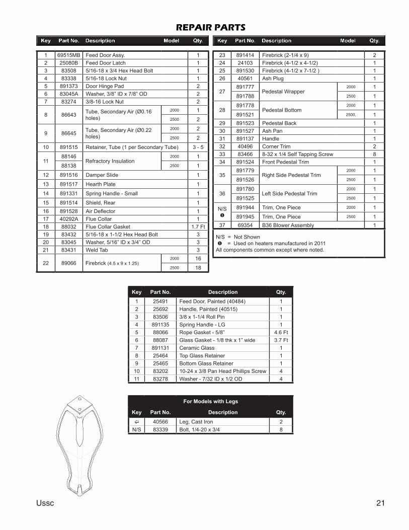
REPAIR PARTS
5 6 7
432
17
18
19
20
21
13
12
27
28
30
29
16
15
37
1
2224 25 26
35
32 3334
36
31
14
23
98
10
11
4
3
15
67
2
9
8
10
11
Feed Door Assembly
Ussc 21
REPAIR PARTS
Key Part No. Description Qty.
1 25491 Feed Door, Painted (40484) 12 25692 Handle, Painted (40515) 13 83506 3/8 x 1-1/4 Roll Pin 14 891135 Spring Handle - LG 15 88066 Rope Gasket - 5/8” 4.6 Ft6 88087 Glass Gasket - 1/8 thk x 1” wide 3.7 Ft7 891131 Ceramic Glass 18 25464 Top Glass Retainer 19 25465 Bottom Glass Retainer 110 83202 10-24 x 3/8 Pan Head Phillips Screw 411 83278 Washer - 7/32 ID x 1/2 OD 4
1 69515MB Feed Door Assy. 12 25080B Feed Door Latch 13 83508 5/16-18 x 3/4 Hex Head Bolt 14 83338 5/16-18 Lock Nut 15 891373 Door Hinge Pad 26 83045A Washer, 3/8” ID x 7/8” OD 27 83274 3/8-16 Lock Nut 2