HR90000 SERIES HOSE REELS PART No. PRODUCT DESCRIPTION PSI/BAR HR90005 EL Series Air and Water complete with 30m x 1" ID hose and hose stop 300psi/20bar HR90010 EL Series Air and Water complete with 15m x 1" ID hose and hose stop 300psi/20bar HR90015 EL Series Air and Water complete with 8m x 1" ID hose and hose stop 300psi/20bar HR90020 EL Series Air and Water complete with 40m x 3/4" ID hose and hose stop 300psi/20bar HR90025 EL Series Air and Water complete with 20m x 3/4" ID hose and hose stop 300psi/20bar HR90030 EL Series Air and Water complete with 12m x 3/4" ID hose and hose stop 300psi/20bar HR90035 EL Series Air and Water complete with 50m x 1/2" ID hose and hose stop 300psi/20bar HR90040 EL Series Air and Water complete with 30m x 1/2" ID hose and hose stop 300psi/20bar HR90045 EL Series Air and Water complete with 25m x 1/2" ID hose and hose stop 300psi/20bar HR90050 EL Series Oil, Fuel and Waste Oil complete with 15m x 1" ID hose and hose stop 1,000psi/69bar HR90055 EL Series Oil, Fuel and Waste Oil complete with 20m x 3/4" ID hose and hose stop 1,250psi/86bar HR90060 EL Series Air and Water complete with 30m x 1/2" ID hose and hose stop 2,000psi/138bar HR90065 EL Series Oil, Fuel and Waste Oil complete with 25m x 1/2" ID hose and hose stop 2,000psi/138bar HR90070 EL Series Grease complete with 30m x 3/8" ID hose and hose stop 4,000psi/276bar HR90075 EL Series Grease complete with 25m x 3/8" ID hose and hose stop 4,000psi/276bar Uses Air, Water, Oil, Fuel and Waste Oil Working Pressures 300-4000psi Materials Steel / S.A.E 100R1, 100R2 and NBR hose NSW TEL: (02) 9677 1555 FAX: (02) 9675 1155 QLD/PNG TEL: (07) 3204 9166 FAX: (07) 3204 1224 VIC/TAS TEL: (03) 8787 8288 FAX: (03) 8787 8266 WA TEL: (08) 9302 4199 FAX: (08) 9303 2095 SA/NT TEL: (08) 8241 7111 FAX: (08) 8241 7011 NZ TEL: (09) 447 1007 FAX: (09) 447 1008 OWNER’S TECHNICAL MANUAL
Transcript
HR90000 SERIES HOSE REELS
PART No. PRODUCT DESCRIPTION PSI/BAR
HR90005 EL Series Air and Water complete with 30m x 1" ID hose and hose stop 300psi/20bar
HR90010 EL Series Air and Water complete with 15m x 1" ID hose and hose stop 300psi/20bar
HR90015 EL Series Air and Water complete with 8m x 1" ID hose and hose stop 300psi/20bar
HR90020 EL Series Air and Water complete with 40m x 3/4" ID hose and hose stop 300psi/20bar
HR90025 EL Series Air and Water complete with 20m x 3/4" ID hose and hose stop 300psi/20bar
HR90030 EL Series Air and Water complete with 12m x 3/4" ID hose and hose stop 300psi/20bar
HR90035 EL Series Air and Water complete with 50m x 1/2" ID hose and hose stop 300psi/20bar
HR90040 EL Series Air and Water complete with 30m x 1/2" ID hose and hose stop 300psi/20bar
HR90045 EL Series Air and Water complete with 25m x 1/2" ID hose and hose stop 300psi/20bar
HR90050 EL Series Oil, Fuel and Waste Oil complete with 15m x 1" ID hose and hose stop 1,000psi/69bar
HR90055 EL Series Oil, Fuel and Waste Oil complete with 20m x 3/4" ID hose and hose stop 1,250psi/86bar
HR90060 EL Series Air and Water complete with 30m x 1/2" ID hose and hose stop 2,000psi/138bar
HR90065 EL Series Oil, Fuel and Waste Oil complete with 25m x 1/2" ID hose and hose stop 2,000psi/138bar
HR90070 EL Series Grease complete with 30m x 3/8" ID hose and hose stop 4,000psi/276bar
HR90075 EL Series Grease complete with 25m x 3/8" ID hose and hose stop 4,000psi/276bar
Uses Air, Water, Oil, Fuel and Waste OilWorking Pressures 300-4000psiMaterials Steel / S.A.E 100R1, 100R2 and NBR hose
NSWTEL: (02) 9677 1555FAX: (02) 9675 1155
QLD/PNGTEL: (07) 3204 9166FAX: (07) 3204 1224
VIC/TASTEL: (03) 8787 8288FAX: (03) 8787 8266
WATEL: (08) 9302 4199FAX: (08) 9303 2095
SA/NTTEL: (08) 8241 7111FAX: (08) 8241 7011
NZTEL: (09) 447 1007FAX: (09) 447 1008
OWNER’S TECHNICAL MANUAL
Visit our website at www.alemlube.com.au www.alemlube.co.nz Email - [email protected]
NSWTEL: (02) 9677 1555FAX: (02) 9675 1155
QLD/PNGTEL: (07) 3204 9166FAX: (07) 3204 1224
VIC/TASTEL: (03) 8787 8288FAX: (03) 8787 8266
WATEL: (08) 9302 4199FAX: (08) 9303 2095
SA/NTTEL: (08) 8241 7111FAX: (08) 8241 7011
NZTEL: (09) 447 1007FAX: (09) 447 1008
Industrial Hose Reel286X Series Instruction
Industrial Hose Reel 286X Series Instruction
Technical Details
1 OF 9REV 11/19/14
WARNING:Read carefully and understand all INSTRUCTIONS before operating. Failure to follow the safety rules and other basic safety precautions may result in serious personal injury.Save these instructions in a safe place and on hand so that they can be read when required.
Visit our website at www.alemlube.com.au www.alemlube.co.nz Email - [email protected]
NSWTEL: (02) 9677 1555FAX: (02) 9675 1155
QLD/PNGTEL: (07) 3204 9166FAX: (07) 3204 1224
VIC/TASTEL: (03) 8787 8288FAX: (03) 8787 8266
WATEL: (08) 9302 4199FAX: (08) 9303 2095
SA/NTTEL: (08) 8241 7111FAX: (08) 8241 7011
NZTEL: (09) 447 1007FAX: (09) 447 1008
Parts and Drawing Instructions for HR90000 Series
Specifications Spring driven drum: for automatic rewind. Locking ratchet: to maintain the desiredlength of hose in use.
Read the following precautions and instructions before you begin assembly or using. Failure to comply with these instructions could result in personal injury or property damage. Keep these instructions in a convenient location for future reference.
Hose Reel Safety Precautions 1. Make sure incoming line pressure does not exceed rated operating pressure for your model
hose reel. 2. Use proper eye protection when assembling and using the hose reel. 3. Assemble the hose reel on a clean workbench. 4. Use soap and water when checking for leaks. 5. Keep children away from the work area.
WARNING: Exposure of skin directly to pressurized air, or fluid could result in severe bodily injury.
Installation of Reel 1) For overhead ceiling mounting: Install reels at least 16.5 feet above the floor.2) If the reel you have purchased does not have hose included, you will need to purchase and
attach. Refer to Specifications on box to determine appropriate hose size and length.3) You will need to purchase appropriate hardware for mounting your new reel.1. The reel base has four 1/2” (or 12.7mm) drilled holes for mounting on a suitable flat surface.
Figure 2 is a template showing the correct location of the 4 mounting holes in the bas2. The reel is supplied with a hose guide roller bracket. The bracket position may be changed
depending on the reel mounting position. Figure 2 shows “ Typical Mounting Positions”. If bracket position needs to be changed, do the following: (1) Pull out some hose and let reel latch. (2) Remove the bolts that attach the guide roller bracket to the support post. (3) Rotate guide roller bracket to correct position, replace bolts and tighten.
3. Using the four holes in the base, mount the reel in the desired location. Be sure to use appropriate hardware and tighten securely.
4. Apply Teflon tape or pipe sealant to supply line threads, attach to reel inlet and tighten. The other end of incoming line can now be connected to desired supply source.
5. If hose has been supplied with reel: Apply Teflon tape or pipe sealant to outlet fitting on reel hose, then attach to desired tool, or nozzle. Check connection for leakage, also check hose reel for correct operation. (Details see Operation section.)
6. If hose stopper adjustment is required, pull hose from reel and allow to latch at desired length. Loosen stopper bolts and slide stopper to a position close to the hose guide. Tighten stopper bolts, and unlatch the reel.
Installation of Hose 1. Securely stabilize the reel. 2. Facing the swivel fitting side of reel: Turn the drum clockwise, by hand, until the rewind
spring is tight, and drum has latched. As an extra precaution while installing new hose, secure drum in the latched position.
Industrial Hose Reel 286X Series Instruction
4 OF 9
3. Insert end of the hose through guide roller bracket, and feed through the opening in the drum flange.
4. Use Teflon tape or pipe sealant on hose fitting threads, screw fitting into swivel and tighten. Note: To avoid damage to the swivel, use a wrench to support the swivel fitting while tightening the hose.
5. Attach hose stopper on the other end of hose, near the outlet fitting. 6. Carefully release drum latch, and slowly allow hose to wind onto the reel.
Note: Final spring tension adjustment is accomplished by adding wraps of hose around the drum (to increase tension) or taking off wraps of hose (to decrease tension). Refer to: Adjustment of Spring Tension.
Visit our website at www.alemlube.com.au www.alemlube.co.nz Email - [email protected]
NSWTEL: (02) 9677 1555FAX: (02) 9675 1155
QLD/PNGTEL: (07) 3204 9166FAX: (07) 3204 1224
VIC/TASTEL: (03) 8787 8288FAX: (03) 8787 8266
WATEL: (08) 9302 4199FAX: (08) 9303 2095
SA/NTTEL: (08) 8241 7111FAX: (08) 8241 7011
NZTEL: (09) 447 1007FAX: (09) 447 1008
Operational Instructions for HR90000 Series
Operation 1. Check reel for correct operation by slowly pulling out the hose. A “clicking” noise will be
heard every half revolution of the drum. 2. To latch the reel, pull out the hose and allow it to retract after hearing the first second or third
“ click”. 3. To unlatch, slowly pull out the hose until the “clicking” noise stops, then let the hose retract
until the hose stop rests against the hose guide. Note: To avoid damage to the reel, always hold on to the hose while it is rewinding.
4. Periodically check the hose condition for wear or damage, and check the swivel fitting for leakage. Replace any worn, damaged, or leaking parts.
Adjustment of Spring Tension 1. Pull out approximately 6ft or 2m of hose and allow the drum to latch. 2. Remove hose stopper from hose, and feed hose back through guide. 3. Wrap the pulled hose one time around the drum to increase tension or un-wrap hose one
time from drum to decrease tension. 4. Re-insert hose through guide, and install stopper onto hose end. 5. Unlatch the Drum and check tension. Pull hose from reel, and adjust stopper position if
necessary.
Replacement of Hose 1. Turn off supply to reel. 2. Pull out all the old hose and lock the reel in this position. Caution: Make sure reel drum is
securely locked and cannot rotate back. 3. Remove two hose clamps from hose. 4. Carefully disconnect hose from swivel joint on side of reel, or male fitting in axle center and
remove old hose. 5. Feed new hose through guide and opening in drum, and connect to swivel. Re-install two
hose clamps, on inside and outside of drum flange. Install stopper on other end of hose in the same position as before.
6. Carefully release the drum latch, and slowly allow the hose to wind onto the reel. Note: Final spring adjustment is accomplished by adding or removing wraps of hose around the drum. (Details see spring tension adjustment).
Spring Canister Warning If the rewind spring fails for any reason: For safety reasons, the manufacturer strongly recommends the replacement of the spring canister be carried out by a professional mechanic.
Limited Warranty 1. The manufacturer warrantees this hose reel against defects in material and craftsmanship, for
a period of 12 months from date of purchase. 2. Hose, if supplied with reel, O-rings, plastic rollers and rubber stopper are deemed to be
normal wear items; not warranted. 3. Manufacturer’s liability is limited to replacement or repair of defective material within the
warranty period, when returned freight prepaid to the distributor or their designated service depot.
4. The warranty does not cover damage caused by accident, misuse or faulty installation. 5. The reel must be installed and maintained in compliance with the instructions.
Industrial Hose Reel 286X Series Instruction
6 OF 9
Industrial Hose Reel 286X Series Instruction
7 OF 9
Part No.
1
2
3
4
5
6
7
8
9
10
11
12
13
14
15
16
17
18
19
20
21
22
23
Description
Base Assembly
Spring
Nut
Screw
Axle Sleeve
Protection Cover
Spring Core
Screw
Hose Assembly
Drum Assembly
Protection Base
Fitting
Support plate 2
Locking Ring Gasket
Screw
End Cap
Hose Assembly
Convert Fitting
Fitting
Thread protector
Valve Assembly
O-Ring
O-Ring
Q’ty
1
1
6
8
1
1
1
6
1
1
1
1
1
1
3
2
1
1
1
1
1
1
1
Part No.
24
25
26
27
28
29
30
31
32
33
34
35
36
37
38
39
40
41
42
43
44
45
Description
Axle Sleeve
Locking Ring
Screw
Screw
Drum 1
Support Plate 1
Bumper Block
Thread protector
Roller
Roller Axle
Roller Base
Roller
Roller Axle
Screw
Ratchet
Ratchet Srping
Washer
Bolt
Washer
Washer
Ball
Nut
Q’ty
1
1
6
6
1
1
1
2
2
2
4
4
2
4
1
1
1
1
1
1
1
1
26 16 4 3729
7 28
3 8
9 30 10 11 12
2 5 41 42394014
25
24 18 21
19
17
3436 33 32
1
35 13
1538
43 44 45
6
23 22
20
31
27
PAGE 7 OF 10
Visit our website at www.alemlube.com.au www.alemlube.co.nz Email - [email protected]
NSWTEL: (02) 9677 1555FAX: (02) 9675 1155
QLD/PNGTEL: (07) 3204 9166FAX: (07) 3204 1224
VIC/TASTEL: (03) 8787 8288FAX: (03) 8787 8266
WATEL: (08) 9302 4199FAX: (08) 9303 2095
SA/NTTEL: (08) 8241 7111FAX: (08) 8241 7011
NZTEL: (09) 447 1007FAX: (09) 447 1008
Exploded and Parts List for HR90015, HR90030, HR90045, HR90065 HR90075
Operation 1. Check reel for correct operation by slowly pulling out the hose. A “clicking” noise will be
heard every half revolution of the drum. 2. To latch the reel, pull out the hose and allow it to retract after hearing the first second or third
“ click”. 3. To unlatch, slowly pull out the hose until the “clicking” noise stops, then let the hose retract
until the hose stop rests against the hose guide. Note: To avoid damage to the reel, always hold on to the hose while it is rewinding.
4. Periodically check the hose condition for wear or damage, and check the swivel fitting for leakage. Replace any worn, damaged, or leaking parts.
Adjustment of Spring Tension 1. Pull out approximately 6ft or 2m of hose and allow the drum to latch. 2. Remove hose stopper from hose, and feed hose back through guide. 3. Wrap the pulled hose one time around the drum to increase tension or un-wrap hose one
time from drum to decrease tension. 4. Re-insert hose through guide, and install stopper onto hose end. 5. Unlatch the Drum and check tension. Pull hose from reel, and adjust stopper position if
necessary.
Replacement of Hose 1. Turn off supply to reel. 2. Pull out all the old hose and lock the reel in this position. Caution: Make sure reel drum is
securely locked and cannot rotate back. 3. Remove two hose clamps from hose. 4. Carefully disconnect hose from swivel joint on side of reel, or male fitting in axle center and
remove old hose. 5. Feed new hose through guide and opening in drum, and connect to swivel. Re-install two
hose clamps, on inside and outside of drum flange. Install stopper on other end of hose in the same position as before.
6. Carefully release the drum latch, and slowly allow the hose to wind onto the reel. Note: Final spring adjustment is accomplished by adding or removing wraps of hose around the drum. (Details see spring tension adjustment).
Spring Canister Warning If the rewind spring fails for any reason: For safety reasons, the manufacturer strongly recommends the replacement of the spring canister be carried out by a professional mechanic.
Limited Warranty 1. The manufacturer warrantees this hose reel against defects in material and craftsmanship, for
a period of 12 months from date of purchase. 2. Hose, if supplied with reel, O-rings, plastic rollers and rubber stopper are deemed to be
normal wear items; not warranted. 3. Manufacturer’s liability is limited to replacement or repair of defective material within the
warranty period, when returned freight prepaid to the distributor or their designated service depot.
4. The warranty does not cover damage caused by accident, misuse or faulty installation. 5. The reel must be installed and maintained in compliance with the instructions.
Industrial Hose Reel 286X Series Instruction
6 OF 9
Industrial Hose Reel 286X Series Instruction
7 OF 9
Part No.
1
2
3
4
5
6
7
8
9
10
11
12
13
14
15
16
17
18
19
20
21
22
23
Description
Base Assembly
Spring
Nut
Screw
Axle Sleeve
Protection Cover
Spring Core
Screw
Hose Assembly
Drum Assembly
Protection Base
Fitting
Support plate 2
Locking Ring Gasket
Screw
End Cap
Hose Assembly
Convert Fitting
Fitting
Thread protector
Valve Assembly
O-Ring
O-Ring
Q’ty
1
1
6
8
1
1
1
6
1
1
1
1
1
1
3
2
1
1
1
1
1
1
1
Part No.
24
25
26
27
28
29
30
31
32
33
34
35
36
37
38
39
40
41
42
43
44
45
Description
Axle Sleeve
Locking Ring
Screw
Screw
Drum 1
Support Plate 1
Bumper Block
Thread protector
Roller
Roller Axle
Roller Base
Roller
Roller Axle
Screw
Ratchet
Ratchet Srping
Washer
Bolt
Washer
Washer
Ball
Nut
Q’ty
1
1
6
6
1
1
1
2
2
2
4
4
2
4
1
1
1
1
1
1
1
1
26 16 4 3729
7 28
3 8
9 30 10 11 12
2 5 41 42394014
25
24 18 21
19
17
3436 33 32
1
35 13
1538
43 44 45
6
23 22
20
31
27
PAGE 8 OF 10
Visit our website at www.alemlube.com.au www.alemlube.co.nz Email - [email protected]
NSWTEL: (02) 9677 1555FAX: (02) 9675 1155
QLD/PNGTEL: (07) 3204 9166FAX: (07) 3204 1224
VIC/TASTEL: (03) 8787 8288FAX: (03) 8787 8266
WATEL: (08) 9302 4199FAX: (08) 9303 2095
SA/NTTEL: (08) 8241 7111FAX: (08) 8241 7011
NZTEL: (09) 447 1007FAX: (09) 447 1008
Exploded and Parts List for HR90010, HR90025, HR90040, HR90050, HR90055, HR90060, HR90070Industrial Hose Reel 286X Series Instruction
8 OF 9
Part No.
1
2
3
4
5
6
7
8
9
10
11
12
13
14
15
16
17
18
19
20
21
22
23
24
25
Description
Base Assembly
Spring
Spring Drum Cover
Nut
Spring Core
Screw
Protection Cover
Spring Core
Axle Sleeve
Screw
Spring Drum Assembly
Screw
Hose Assembly
Drum Assembly
Protection Base
Fitting
Support plate 2
Locking Ring Gasket
Screw
End Cap
Hose Assembly
Convert Fitting
Fitting
Thread protector
Valve Assembly
Q’ty
1
2
1
6
1
8
1
1
2
6
2
8
1
1
1
1
1
1
3
2
1
1
1
1
1
Part No.
26
27
28
29
30
31
32
33
34
35
36
37
38
39
40
41
42
43
44
45
46
47
48
49
Description
O-Ring
O-Ring
Axle Sleeve
Locking Ring
Screw
Screw
Drum 1
Support Plate 1
Bumper Block
Thread protector
Roller
Roller Axle
Roller Base
Roller
Roller Axle
Screw
Ratchet
Ratchet Srping
Washer
Bolt
Washer
Washer
Ball
Nut
Q’ty
1
1
1
1
6
6
1
1
1
2
2
2
4
4
2
4
1
1
1
1
1
1
1
1
Industrial Hose Reel 286X Series Instruction
9 OF 9
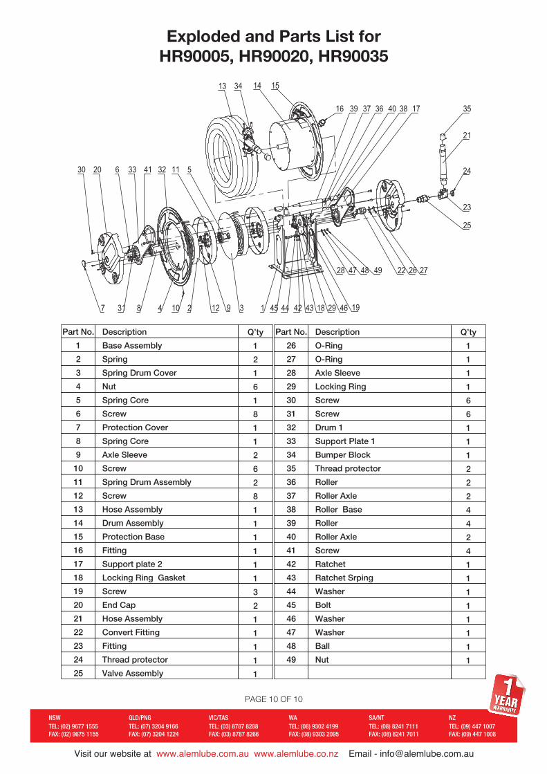
Part No.
1
2
3
4
5
6
7
8
9
10
11
12
13
14
15
16
17
18
19
20
21
22
23
24
25
Description
Base Assembly
Spring
Spring Drum Cover
Nut
Spring Core
Screw
Protection Cover
Spring Core
Axle Sleeve
Screw
Spring Drum Assembly
Screw
Hose Assembly
Drum Assembly
Protection Base
Fitting
Support plate 2
Locking Ring Gasket
Screw
End Cap
Hose Assembly
Convert Fitting
Fitting
Thread protector
Valve Assembly
Q’ty
1
2
1
6
1
8
1
1
2
6
2
8
1
1
1
1
1
1
3
2
1
1
1
1
1
Part No.
26
27
28
29
30
31
32
33
34
35
36
37
38
39
40
41
42
43
44
45
46
47
48
49
Description
O-Ring
O-Ring
Axle Sleeve
Locking Ring
Screw
Screw
Drum 1
Support Plate 1
Bumper Block
Thread protector
Roller
Roller Axle
Roller Base
Roller
Roller Axle
Screw
Ratchet
Ratchet Srping
Washer
Bolt
Washer
Washer
Ball
Nut
Q’ty
1
1
1
1
6
6
1
1
1
2
2
2
4
4
2
4
1
1
1
1
1
1
1
1
30 20 6 33 41 32
104 2 12 9
11 5
3 1 45 4642 43 2918 19
17
22 27
25
21
23
16
151413 34
384039 37 36
24
7
35
44
47 48 49
8
28 26
31
30 20 6 33 41 32
104 2 12 9
11 5
3 1 45 4642 43 2918 19
17
22 27
25
21
23
16
151413 34
384039 37 36
24
7
35
44
47 48 49
8
28 26
31
Size: 145x210mm REV 11/19/14 3.02.01.110157克铜版纸
PAGE 9 OF 10
Visit our website at www.alemlube.com.au www.alemlube.co.nz Email - [email protected]
NSWTEL: (02) 9677 1555FAX: (02) 9675 1155
QLD/PNGTEL: (07) 3204 9166FAX: (07) 3204 1224
VIC/TASTEL: (03) 8787 8288FAX: (03) 8787 8266
WATEL: (08) 9302 4199FAX: (08) 9303 2095
SA/NTTEL: (08) 8241 7111FAX: (08) 8241 7011
NZTEL: (09) 447 1007FAX: (09) 447 1008
Exploded and Parts List for HR90005, HR90020, HR90035Industrial Hose Reel 286X Series Instruction