catalysts Article Oxidative Steam Reforming of Raw Bio-Oil over Supported and Bulk Ni Catalysts for Hydrogen Production Aitor Arandia 1 , Aingeru Remiro 1, * ID , Verónica García 2 , Pedro Castaño 1 ID , Javier Bilbao 1 and Ana G. Gayubo 1 1 Chemical Engineering Department, University of the Basque Country, P.O. Box 644, 48080 Bilbao, Spain; [email protected] (A.A.); [email protected] (P.C.); [email protected] (J.B.); [email protected] (A.G.G.) 2 Grupo de Investigación en Química Estructural GIQUE, Universidad Industrial de Santander, 680002 Bucaramanga, Colombia; [email protected]* Correspondence: [email protected]; Tel.: +34-946-015-361; Fax: +34-946-013-500 Received: 25 July 2018; Accepted: 6 August 2018; Published: 8 August 2018 Abstract: Several Ni catalysts of supported (on La 2 O 3 -αAl 2 O 3 , CeO 2 , and CeO 2 -ZrO 2 ) or bulk types (Ni-La perovskites and NiAl 2 O 4 spinel) have been tested in the oxidative steam reforming (OSR) of raw bio-oil, and special attention has been paid to the catalysts’ regenerability by means of studies on reaction-regeneration cycles. The experimental set-up consists of two units in series, for the separation of pyrolytic lignin in the first step (at 500 ◦ C) and the on line OSR of the remaining oxygenates in a fluidized bed reactor at 700 ◦ C. The spent catalysts have been characterized by N 2 adsorption-desorption, X-ray diffraction and temperature programmed reduction, and temperature programmed oxidation (TPO). The results reveal that among the supported catalysts, the best balance between activity-H 2 selectivity-stability corresponds to Ni/La 2 O 3 -αAl 2 O 3 , due to its smaller Ni 0 particle size. Additionally, it is more selective to H 2 than perovskite catalysts and more stable than both perovskites and the spinel catalyst. However, the activity of the bulk NiAl 2 O 4 spinel catalyst can be completely recovered after regeneration by coke combustion at 850 ◦ C because the spinel structure is completely recovered, which facilitates the dispersion of Ni in the reduction step prior to reaction. Consequently, this catalyst is suitable for the OSR at a higher scale in reaction-regeneration cycles. Keywords: bio-oil; Ni catalyst; oxidative steam reforming; H 2 production; deactivation; regeneration 1. Introduction The world energy industrial sector is in a technological transition stage from the traditional processes for obtaining energy from non-renewable sources (oil, coal, natural gas) towards new sustainable and environmentally friendly processes, with the objective of attaining in the middle-term a neutral balance of greenhouse gases emissions. In this scenario, the development of sustainable H 2 production technologies plays a significant role [1–3], with a special interest in the routes from lignocellulosic biomass [4,5] due to its high availability and whose valorisation does not interfere in the feeding chain. Among these routes from biomass, great attention is paid to the H 2 production by steam reforming (SR) of bio-oil, the liquid product from the pyrolysis of lignocellulosic biomass [6–8]. Bio-oil can be obtained in a decentralised way by means of fast pyrolysis, with simple and environmentally friendly technologies, which are in industrialisation development [9]. In spite of its renewable nature, the low content of S and N, and neutral CO 2 balance for combustion, bio-oil is not suitable for direct use as a fuel due to its instability and properties (such as high water and oxygen Catalysts 2018, 8, 322; doi:10.3390/catal8080322 www.mdpi.com/journal/catalysts
Transcript
catalysts
Article
Oxidative Steam Reforming of Raw Bio-Oil overSupported and Bulk Ni Catalysts forHydrogen Production
Aitor Arandia 1, Aingeru Remiro 1,* ID , Verónica García 2, Pedro Castaño 1 ID , Javier Bilbao 1
Received: 25 July 2018; Accepted: 6 August 2018; Published: 8 August 2018�����������������
Abstract: Several Ni catalysts of supported (on La2O3-αAl2O3, CeO2, and CeO2-ZrO2) or bulk types(Ni-La perovskites and NiAl2O4 spinel) have been tested in the oxidative steam reforming (OSR) ofraw bio-oil, and special attention has been paid to the catalysts’ regenerability by means of studieson reaction-regeneration cycles. The experimental set-up consists of two units in series, for theseparation of pyrolytic lignin in the first step (at 500 ◦C) and the on line OSR of the remainingoxygenates in a fluidized bed reactor at 700 ◦C. The spent catalysts have been characterized by N2
adsorption-desorption, X-ray diffraction and temperature programmed reduction, and temperatureprogrammed oxidation (TPO). The results reveal that among the supported catalysts, the best balancebetween activity-H2 selectivity-stability corresponds to Ni/La2O3-αAl2O3, due to its smaller Ni0
particle size. Additionally, it is more selective to H2 than perovskite catalysts and more stable thanboth perovskites and the spinel catalyst. However, the activity of the bulk NiAl2O4 spinel catalyst canbe completely recovered after regeneration by coke combustion at 850 ◦C because the spinel structureis completely recovered, which facilitates the dispersion of Ni in the reduction step prior to reaction.Consequently, this catalyst is suitable for the OSR at a higher scale in reaction-regeneration cycles.
The world energy industrial sector is in a technological transition stage from the traditionalprocesses for obtaining energy from non-renewable sources (oil, coal, natural gas) towards newsustainable and environmentally friendly processes, with the objective of attaining in the middle-terma neutral balance of greenhouse gases emissions. In this scenario, the development of sustainableH2 production technologies plays a significant role [1–3], with a special interest in the routesfrom lignocellulosic biomass [4,5] due to its high availability and whose valorisation does notinterfere in the feeding chain. Among these routes from biomass, great attention is paid to the H2
production by steam reforming (SR) of bio-oil, the liquid product from the pyrolysis of lignocellulosicbiomass [6–8]. Bio-oil can be obtained in a decentralised way by means of fast pyrolysis, with simpleand environmentally friendly technologies, which are in industrialisation development [9]. In spite ofits renewable nature, the low content of S and N, and neutral CO2 balance for combustion, bio-oil isnot suitable for direct use as a fuel due to its instability and properties (such as high water and oxygen
content, acidity, corrosiveness and low viscosity). Consequently, several processes have been proposedfor stabilizing, conditioning and up-grading bio-oil in order to convert it into platform chemicals(olefins and BTX), liquid fuels or H2 [10–12]. Thus, the bio-oil produced in decentralised pyrolysisunits can be subsequently transported to a centralized unit for H2 production. This transport is moreeconomical than that of the biomass, due to the higher density of bio-oil [13]. Compared to otherroutes for valorising bio-oil, steam reforming has the additional advantage that it does not requirewater separation.
The SR of bio-oil is a highly endothermic reaction [6,8,14] that follows the general stoichiometryof oxygenates reforming, Equation (1), and considering the water gas shift reaction, Equation (2),the complete stoichiometry of this overall reaction is given by Equation (3).
CnHmOk + (n − k)H2O→ nCO + (n + m/2 − k)H2 (1)
CO + H2O↔ CO2 + H2 (2)
CnHmOk + (2n − k)H2O→ nCO2 + (2n + m/2 − k)H2 (3)
The addition of oxygen together with water promotes the partial oxidation of some compoundsin the reaction medium, thus decreasing the energy requirements for the endothermic steam reformingreaction, although to the expense of a lower H2 production. This reaction is known as oxidativesteam reforming (OSR) (Equation (4)) and with a suitable ratio of O2/steam/carbon in the feed,a thermoneutral regime can be achieved [14,15].
In addition to the reforming reaction, secondary reactions (cracking/decomposition methanation,Boudouard reaction) can also take place, thus decreasing the potential H2 production.
Due to the difficulty in handling bio-oil because of its complex nature (a mixture with more than300 oxygenated compounds belonging to different families), the SR and OSR has been extensivelystudied with pure oxygenates, mainly ethanol [16–18], and OSR experimental studies with raw bio-oilhave been scarcely addressed in the literature [19,20]. Remiro et al. [15] reported the better performancein the OSR of raw bio-oil at 700 ◦C of a Rh/CeO2-ZrO2 catalyst over a supported Ni/La2O3-αAl2O3
catalyst due to the higher activity and stability of the former. The higher stability of the Rh catalyst wasattributed to a lower encapsulating coke deposition and much lower metal sintering compared to theNi catalyst. Nevertheless, in the conditions needed for attaining high bio-oil conversion (above 600 ◦C),the Rh/CeO2-ZrO2 catalyst suffers structural changes, both in the Rh species and in the support(aging) [21], which is a handicap for the total recovery of its activity subsequent to regeneration bytotal coke removal by combustion with air [22]. This fact, together with the high cost of the Rh-basedcatalyst, advice us to continue searching for cheaper catalysts with suitable performance in the OSR ofraw bio-oil.
With this background, the objective of this work has been the selection of a suitable catalyst forthe OSR of raw bio-oil, based on the best compromise between activity, H2 selectivity, and stabilityin the selected reaction conditions, but paying special attention to its capacity for activity recoveryafter regeneration, as this is a key factor for the industrial viability of the process which has beenscarcely studied in the literature. For that purpose, Ni-based catalysts have been selected due totheir good performance for reforming of oxygenated compounds and lower cost compared to noblemetal catalysts. The catalysts studied include (i) supported catalysts, prepared in the laboratory withdifferent supports (La2O3-Al2O3, CeO2, CeO2-ZrO2) and a commercial catalyst (G90) for comparison.The variety of studied supports has allowed analysing the relevance of the metal-support interactionon the Ni catalyst properties and, consequently, on their catalytic behaviour, and; (ii) bulk catalysts, ofNi-La perovskite-type (LaNiO3 and L2NiO4) and Ni-Al spinel type (NiAl2O4). The estate of Ni and themetal-support interaction will affect the ability for the adsorption of the chemical compounds in the
Catalysts 2018, 8, 322 3 of 25
reaction medium and, consequently, their reactivity. Thus, Politano and Chiarello [23] have proven therelevance of the co-adsorption of other compounds in the reaction medium on the adsorption of COon Ni sites, with the formation of intermediate COH with the adsorbed H. This complex behaviour ofNi sites makes the interpretation of the results difficult. The experimental runs were carried out in anexperimental device with two units in series (thermal step and catalytic step, the latter in fluidized bedreactor), whose adequacy for SR and OSR of aqueous and raw bio-oil has been previously proven, as itminimizes operating problems (such as plugging of reactor piping) as well as catalyst deactivation inthe reforming step [15,21,22,24–27]. The properties of the catalysts have been determined with differenttechniques (N2 adsorption-desorption, Temperature Programmed Reduction (TPR), X-ray Diffraction(XRD)), in order to explain the differences in the kinetic behaviour of the catalysts. The activity recoveryhas been studied by means of reaction-regeneration cycles, with regeneration involving combustionwith air for complete coke removal.
Tables 1 and 2 show the physical properties (BET Surface, pore volume, and mean porediameter) of the supported and bulk catalysts, respectively, obtained from the corresponding N2
adsorption-desorption isotherms. The differences in the physical properties of the supported catalysts(Table 1) can be attributed to the differences in their corresponding support, with the BET surfaceof CeO2 support (Ce) (191.8 m2 g−1) being much higher than that of La2O3-αAl2O3 (LaAl) and theCeO2-ZrO2 (CeZr) supports (41.4 m2 g−1 and 47.5 m2 g−1, respectively). Consequently, the Ni/Cecatalyst has the higher porosity, with the values of BET Surface, pore volume, and pore diameter(159.2 m2 g−1, 0.312 cm3 g−1 and 8.2 nm, respectively) lower than the Ce support due to the partialblockage by Ni [28]. The decrease in the support accessibility after impregnation is also observed forthe Ni catalysts supported on CeZr and on LaAl, in accordance with the literature [29–31]. For Ni/CeZrcatalysts, an increase in the Ni content involves a decrease in surface area and pore volume, but themean pore diameter increases slightly compared to the support due to the blockage of the pores oflower diameter. The Ni commercial catalyst, G90, has the lower specific surface area and pore volumeamong the studied supported catalysts.
Table 1. The physical properties of the supports, of the synthetized supported catalysts, and of thecommercial G90 catalyst.
The low values of BET surface area observed in Table 2 for the Ni-La perovskites are characteristicfor these materials with low porosity [32,33]. Nevertheless, there are differences between the two
Catalysts 2018, 8, 322 4 of 25
types of perovskites due to the meso-macroporosity of LaNiO3 catalyst, so that the meso-macroporevolume of this catalyst (0.068 cm3 g−1, calculated as the difference between total pore volume and thatof micropore) is significantly higher than that of La2NiO4 catalyst (0.012 cm3 g−1). The BET surfacearea of the Ni-Al spinel type catalyst is significantly higher than those of the perovskite-type, and it isalso noticeably higher than that of supported catalysts, except Ni/Ce.
Table 2. The physical properties of the synthetized bulk catalysts of Ni-La perovskite-type and Ni-Alspinel type.
Figures 1 and 2 show the TPR profiles of the supported and bulk catalysts, respectively. From theseprofiles, the reduction temperature for each catalyst has been selected (Table 4 in Section 4) in order toobtain the metal active species (Ni0).
The TPR profiles of the Ni supported catalysts differ depending on the Ni content and on thesupport (Figure 1), Ni/LaAl and G90 being those requiring a higher temperature for the reduction ofall the oxidized metal species. These results give evidence of the important role of the support and themetal-support interaction on the metal reducibility, so that the Ni-Al2O3 interactions are stronger thanthe interactions of Ni with CeO2 and/or ZrO2 oxides [34,35].
Catalysts 2018, 8, x FOR PEER REVIEW 4 of 24
Table 2. The physical properties of the synthetized bulk catalysts of Ni-La perovskite-type and Ni-Al spinel type.
Figures 1 and 2 show the TPR profiles of the supported and bulk catalysts, respectively. From these profiles, the reduction temperature for each catalyst has been selected (Table 4 in Section 4) in order to obtain the metal active species (Ni0).
The TPR profiles of the Ni supported catalysts differ depending on the Ni content and on the support (Figure 1), Ni/LaAl and G90 being those requiring a higher temperature for the reduction of all the oxidized metal species. These results give evidence of the important role of the support and the metal-support interaction on the metal reducibility, so that the Ni-Al2O3 interactions are stronger than the interactions of Ni with CeO2 and/or ZrO2 oxides [34,35].
Figure 1. The TPR profiles for the Ni supported catalysts.
Two wide and asymmetric reduction domains are observed for Ni/LaAl catalyst: the reduction to Ni0 of surface NiO with low interaction with the support takes place in the 250–370 °C range, whereas the band between 370–700 °C corresponds to the reduction to Ni0 of well dispersed NiOx species, probably of an amorphous nature and with high interaction with the support [25]. A reduction peak of low intensity is also observed above 700 °C for the Ni/LaAl catalyst that corresponds to the reduction to Ni0 of the Ni2+ in the spinel phase (NiAl2O4), whose low intensity is explained by its low calcination temperature (550 °C) because the formation of the spinel requires higher temperatures [25,36]. The commercial catalyst G90 has the main reduction peak with a maximum near 420 °C, attributed to the reduction of NiO with a slight interaction with the αAl2O3 support, and a peak near 680 °C probably related to the reduction of Ni2+ in the NiAl2O4 phase, according to the composition given by the provider (Sud-Chemie). The Ni/Ce catalyst has two
0 200 400 600 800
G90
15Ni/CeZr
5Ni/CeZr
Ni/Ce
TC
D S
igna
l, ar
b.un
its
Temperature, ºC
Ni/LaAl
Figure 1. The TPR profiles for the Ni supported catalysts.
Two wide and asymmetric reduction domains are observed for Ni/LaAl catalyst: the reduction toNi0 of surface NiO with low interaction with the support takes place in the 250–370 ◦C range, whereasthe band between 370–700 ◦C corresponds to the reduction to Ni0 of well dispersed NiOx species,
Catalysts 2018, 8, 322 5 of 25
probably of an amorphous nature and with high interaction with the support [25]. A reductionpeak of low intensity is also observed above 700 ◦C for the Ni/LaAl catalyst that corresponds tothe reduction to Ni0 of the Ni2+ in the spinel phase (NiAl2O4), whose low intensity is explainedby its low calcination temperature (550 ◦C) because the formation of the spinel requires highertemperatures [25,36]. The commercial catalyst G90 has the main reduction peak with a maximumnear 420 ◦C, attributed to the reduction of NiO with a slight interaction with the αAl2O3 support,and a peak near 680 ◦C probably related to the reduction of Ni2+ in the NiAl2O4 phase, according tothe composition given by the provider (Sud-Chemie). The Ni/Ce catalyst has two reduction peaks,a minority and wide peak below 250 ◦C and a main peak in the 250–400 ◦C range, which correspondto the reduction of the NiO species with different interaction strengths with CeO2 support [37].Moreover, the possible reduction of the CeO2 support around 400 ◦C should be also taken intoaccount, and this reduction peak can overlap the NiO reduction peak as a consequence of the “spillover”phenomena [38,39]. The reduction peak with a maximum at 360 ◦C for Ni catalysts supported onCeO2-ZrO2 corresponds to the reduction of NiO interacting with the support. In the catalyst withhigher Ni content (15Ni/CeZr), there is another reduction peak at lower temperature (with a maximumbelow 300 ◦C), that can be attributed to the reduction of free NiO species or with weak metal-supportinteraction [40,41], probably due to the high metal content in the catalyst.
In the Ni-La perovskite-type catalysts, two well-differenced reduction bands are observed(Figure 2), that shift towards higher temperature for the La2NiO4 catalyst, which evidences a higherinteraction between Ni and La2O3 compared to the LaNiO3 catalyst [42]. For the latter, the tworeduction bands, with maximum at 280 and 420 ◦C, correspond to the reduction of the LaNiO3
precursor in two consecutive steps: firstly, the reduction of Ni3+ species to Ni2+ takes place, thusforming La2Ni2O5, which is reduced in the second step at higher temperature to form Ni0 andLa2O3 [43–45]. Nevertheless, there is no agreement in the literature concerning the assignment ofreduction peaks for the La2NiO4 catalyst. Thus, some authors attribute the first peak to the reductionof Ni3+ to Ni2+ and the second peak to the reduction of Ni2+ to Ni0 [46,47], but others assume thatfirstly there is a reduction of the excess oxygen in the La2NiO4+δ phase, and that the reduction of theresulting La2NiO4 phase takes place in one step, near 600 ◦C [48,49].
Catalysts 2018, 8, x FOR PEER REVIEW 5 of 24
reduction peaks, a minority and wide peak below 250 °C and a main peak in the 250–400 °C range, which correspond to the reduction of the NiO species with different interaction strengths with CeO2 support [37]. Moreover, the possible reduction of the CeO2 support around 400 °C should be also taken into account, and this reduction peak can overlap the NiO reduction peak as a consequence of the “spillover” phenomena [38,39]. The reduction peak with a maximum at 360 °C for Ni catalysts supported on CeO2-ZrO2 corresponds to the reduction of NiO interacting with the support. In the catalyst with higher Ni content (15Ni/CeZr), there is another reduction peak at lower temperature (with a maximum below 300 °C), that can be attributed to the reduction of free NiO species or with weak metal-support interaction [40,41], probably due to the high metal content in the catalyst.
In the Ni-La perovskite-type catalysts, two well-differenced reduction bands are observed (Figure 2), that shift towards higher temperature for the La2NiO4 catalyst, which evidences a higher interaction between Ni and La2O3 compared to the LaNiO3 catalyst [42]. For the latter, the two reduction bands, with maximum at 280 and 420 °C, correspond to the reduction of the LaNiO3 precursor in two consecutive steps: firstly, the reduction of Ni3+ species to Ni2+ takes place, thus forming La2Ni2O5, which is reduced in the second step at higher temperature to form Ni0 and La2O3 [43–45]. Nevertheless, there is no agreement in the literature concerning the assignment of reduction peaks for the La2NiO4 catalyst. Thus, some authors attribute the first peak to the reduction of Ni3+ to Ni2+ and the second peak to the reduction of Ni2+ to Ni0 [46,47], but others assume that firstly there is a reduction of the excess oxygen in the La2NiO4+δ phase, and that the reduction of the resulting La2NiO4 phase takes place in one step, near 600 °C [48,49].
Figure 2. The TPR profiles for the bulk catalysts of Ni-La perovskite and Ni-Al spinel type.
The NiAl2O4 spinel catalyst has the main reduction peak with a maximum at 800 °C in Figure 2, corresponding to the reduction of Ni+2 ions incorporated in the spinel structure, which require high temperatures for breaking the strong bonds [25,50]. The presence of a smaller band with a maximum near 450 °C, corresponding to the reduction to Ni0 of the NiO with a high interaction with the support, but not being part of the spinel structure, can be due to the use of an excess of Ni or defect of Al in the synthesis of this catalyst. It could be also attributed to the difficulty of the auto-combustion method for attaining a complete reaction between NiO and Al2O3 so that Ni is not completely incorporated in the NiAl2O4 spinel structure.
Figure 3 shows the X-ray diffractograms for the supported catalysts prior and after reduction (fresh or reduced, respectively), whereas those corresponding to the bulk catalysts are shown in Figure 4. Up to five phases are observed for the Ni/LaAl catalyst, depending on the oxidation state of the sample (Figure 3). Al2O3, NiAl2O4, and LaAlO3 phases are observed in both states (oxidized and
0 200 400 600 800
NiAl2O
4
La2NiO
4
LaNiO3
TC
D S
igna
l, ar
b.un
its
Temperature, ºC
Figure 2. The TPR profiles for the bulk catalysts of Ni-La perovskite and Ni-Al spinel type.
The NiAl2O4 spinel catalyst has the main reduction peak with a maximum at 800 ◦C in Figure 2,corresponding to the reduction of Ni+2 ions incorporated in the spinel structure, which require hightemperatures for breaking the strong bonds [25,50]. The presence of a smaller band with a maximumnear 450 ◦C, corresponding to the reduction to Ni0 of the NiO with a high interaction with the support,but not being part of the spinel structure, can be due to the use of an excess of Ni or defect of Al in the
Catalysts 2018, 8, 322 6 of 25
synthesis of this catalyst. It could be also attributed to the difficulty of the auto-combustion methodfor attaining a complete reaction between NiO and Al2O3 so that Ni is not completely incorporated inthe NiAl2O4 spinel structure.
Figure 3 shows the X-ray diffractograms for the supported catalysts prior and after reduction(fresh or reduced, respectively), whereas those corresponding to the bulk catalysts are shown inFigure 4. Up to five phases are observed for the Ni/LaAl catalyst, depending on the oxidation state ofthe sample (Figure 3). Al2O3, NiAl2O4, and LaAlO3 phases are observed in both states (oxidized andreduced), whereas NiO is only observed in the oxidized simple and Ni0 is only present in the reducedsample. The small fraction of NiAl2O4 identified in this catalyst (whose formation is incipient in thecalcination at 550 ◦C [25]) is coherent with the small shoulder above 700 ◦C observed in the TPR profileof this catalyst (Figure 1). This oxidized species remains in the reduced simple because its reduction toNi0 requires a temperature above 700 ◦C.
Catalysts 2018, 8, x FOR PEER REVIEW 6 of 24
reduced), whereas NiO is only observed in the oxidized simple and Ni0 is only present in the reduced sample. The small fraction of NiAl2O4 identified in this catalyst (whose formation is incipient in the calcination at 550 °C [25]) is coherent with the small shoulder above 700 °C observed in the TPR profile of this catalyst (Figure 1). This oxidized species remains in the reduced simple because its reduction to Ni0 requires a temperature above 700 °C.
Figure 3. The X-ray diffractograms of the synthetized Ni supported catalysts, prior to reduction (fresh) and after reduction at 700 °C.
The diffraction peaks corresponding to NiO (fresh samples) and Ni0 (reduced samples) are also observed for the catalysts supported on Ce or CeZr (Ni/Ce, 5Ni/CeZr, and 15Ni/CeZr), although the peaks of these phases for 5Ni/CeZr catalyst are of low intensity due to its low Ni content (5 wt %). Peaks corresponding to CeO2 phase are also identified in the diffractograms of the three catalysts, which are characteristic of the fluorite structure [51,52]. The doping of CeO2 with ZrO2 (5/NiCeZr and 15Ni/CeZr catalysts) slightly shifts the peaks of the CeO2 support towards higher values of diffraction angle (2θ), which is characteristic of the incorporation of Zr+4 ions in the structure of CeO2 [53,54].
10 20 30 40 50 60 70 80
Δ
Δ
Δ
Δ
Δ
Δ
Δ
Δ
Δ
Δ
Δ
Δ
o CexZr1-xO2
Ni/Ce
5Ni/CeZr
15Ni/CeZr
o
o
o
o
o
o
o
o
oo
o
o
o
o
o
o
*
*
*
*
*
*
*
*
*
♦
♦♦
♦
♦
♦
♦
•
•
•
•
•
•
•
•
•
•
•
•
• ××
××
×
×
×
×
×
×
×
×
×
×
×
×
×
***
* Ni0 Al2O3
Reduced
Inte
nsit
y, a
rb. u
nits
2θ, °
Fresh
NiAl2O4LaAlO3NiO
Ni/LaAl
Fresh
Reduced
Fresh
Reduced
Fresh
Reduced
oo
oo
oo
oo
CeO2
Δ
Figure 3. The X-ray diffractograms of the synthetized Ni supported catalysts, prior to reduction (fresh)and after reduction at 700 ◦C.
Catalysts 2018, 8, 322 7 of 25
The diffraction peaks corresponding to NiO (fresh samples) and Ni0 (reduced samples) are alsoobserved for the catalysts supported on Ce or CeZr (Ni/Ce, 5Ni/CeZr, and 15Ni/CeZr), although thepeaks of these phases for 5Ni/CeZr catalyst are of low intensity due to its low Ni content (5 wt %).Peaks corresponding to CeO2 phase are also identified in the diffractograms of the three catalysts,which are characteristic of the fluorite structure [51,52]. The doping of CeO2 with ZrO2 (5/NiCeZr and15Ni/CeZr catalysts) slightly shifts the peaks of the CeO2 support towards higher values of diffractionangle (2θ), which is characteristic of the incorporation of Zr+4 ions in the structure of CeO2 [53,54].
The X-ray diffractogram of the reduced commercial G90 catalyst was reported elsewhere [55],and it evidenced a complex structure, with up to six crystalline phases corresponding to Ni0, NiO,Al2O3, CaO(Al2O3)2, CaAl2O4, and CaAl12O19.
Catalysts 2018, 8, x FOR PEER REVIEW 7 of 24
The X-ray diffractogram of the reduced commercial G90 catalyst was reported elsewhere [55], and it evidenced a complex structure, with up to six crystalline phases corresponding to Ni0, NiO, Al2O3, CaO(Al2O3)2, CaAl2O4, and CaAl12O19.
Figure 4. The X-ray diffractograms of the bulk catalysts, type perovskite Ni-La and spinel NiAl2O4, prior to reduction (fresh) or after reduction.
The only phase observed in the X-ray diffractogram of the LaNiO3 perovskite prior to reduction is LaNiO3 (Figure 4), which evidences the efficiency of the auto-combustion method used for obtaining this catalyst. Nevertheless, in the X-ray diffractogram of the La2NiO4 perovskite, the presence of La2O3 species is observed, together with La2NiO4, which could be due to the need of a higher calcination temperature or to a defect in the amount of the fuel (glycine) in the synthesis by auto-combustion, which hampers the compete combustion reaction [56]. After the reduction of both perovskite-type catalysts, the only species observed are Ni0 and La2O3. The X-ray diffractogram of the fresh NiAl2O4 catalyst shows diffraction peaks corresponding to two different Ni species, NiAl2O4 and NiO, in agreement with the TRP profile in Figure 2, whereas in the diffractogram of the reduced sample the only species identified are Ni0 and Al2O3, which proves the complete reduction of Ni2+ in the spinel phase to Ni0.
By means of the Scherrer equation, the average Ni0 crystallite size has been determined for all the catalysts (Table 3). The value corresponding to the diffraction angle 2θ = 51.8 has not been estimated for 5Ni/CeZr catalyst due to the low intensity of the corresponding diffraction peak. This
10 20 30 40 50 60 70 80
ooo oo
*
*
*
♦
♦
♦
♦
♦ ♦
2θ, °
ooooo
o
oo
o
o
oooo
o
o
oo
o
o
oooo
oo
o
Reduced
Fresh
La2NiO
4
LaNiO3
La2NiO4♦
*
****
*
*
*
♦ ♦♦♦♦♦
♦♦♦
♦♦♦♦
♦
♦
♦
♦
Inte
nsit
y, a
.u. LaNiO3La2O3
Reduced
Fresh
Ni0
♦ NiAl2O4
* NiOo Al2O3
Ni0
La2O3o
Ni0
NiAl2O
4
Fresh
Reduced
Inte
nsit
y, a
rb.u
nits LaNiO3
Figure 4. The X-ray diffractograms of the bulk catalysts, type perovskite Ni-La and spinel NiAl2O4,prior to reduction (fresh) or after reduction.
The only phase observed in the X-ray diffractogram of the LaNiO3 perovskite prior to reduction isLaNiO3 (Figure 4), which evidences the efficiency of the auto-combustion method used for obtainingthis catalyst. Nevertheless, in the X-ray diffractogram of the La2NiO4 perovskite, the presence of La2O3
species is observed, together with La2NiO4, which could be due to the need of a higher calcinationtemperature or to a defect in the amount of the fuel (glycine) in the synthesis by auto-combustion,
Catalysts 2018, 8, 322 8 of 25
which hampers the compete combustion reaction [56]. After the reduction of both perovskite-typecatalysts, the only species observed are Ni0 and La2O3. The X-ray diffractogram of the fresh NiAl2O4
catalyst shows diffraction peaks corresponding to two different Ni species, NiAl2O4 and NiO,in agreement with the TRP profile in Figure 2, whereas in the diffractogram of the reduced sample theonly species identified are Ni0 and Al2O3, which proves the complete reduction of Ni2+ in the spinelphase to Ni0.
By means of the Scherrer equation, the average Ni0 crystallite size has been determined for all thecatalysts (Table 3). The value corresponding to the diffraction angle 2θ = 51.8 has not been estimatedfor 5Ni/CeZr catalyst due to the low intensity of the corresponding diffraction peak. This value isnot shown for the perovskites either, because the peak corresponding to La2O3 phase overlaps andinterferes highly with the signal.
The lower Ni0 particle size corresponds to the Ni/LaAl catalyst, with an average size near 8 nm.The average particle size for the rest of the catalysts is significantly higher, which evidences thestabilizing effect of the LaAl support (mainly the La2O3 phase), which attenuates the aggregation ofmetal particles during the reduction [57,58]. The increase in Ni content from 5 to 15 wt % disfavoursits dispersion in the CeZr support, with an increase in the average crystallite size from 21.4 to 34.2 nm.Regarding the bulk catalysts, the perovskites have a crystallite size lower than the NiAl2O4 spinel,which is coherent with the previously mentioned stabilizing effect of La2O3 for attenuating theagglomeration of the metal. The higher crystallite size in the LaNiO3 catalyst (14.2 nm) compared tothe La2NiO4 catalyst (11.6 nm), has been also previously observed by Guo et al. [42], who attributedthis result to the higher content of Ni in the LaNiO3 catalysts, which hinders its dispersion.
Table 3. The average size of the Ni0 crystallite for the reduced supported and bulk catalysts, determinedfrom diffraction angles 44.5◦ (plane 111) and 51.8◦ (plane 200).
The performance of the catalysts in the OSR of raw bio-oil has been compared under the operatingconditions indicated in Section 4.3, which were selected according to the previous results on the SR andOSR of bio-oil [15,21,26,27]. These conditions (700 ◦C, S/C = 6, O/C = 0.34, with low space-time values)provide high bio-oil conversion and H2 yield, but with quite a rapid deactivation of the catalysts (dueto the low space-time), in order to allow a rapid comparison of the catalysts stability. The resultscorresponding to the supported catalyst are presented in Section 2.2.1, whereas those corresponding tothe bulk catalysts (together with the best-supported catalyst) are compared in Section 2.2.2.
2.2.1. Supported Catalysts
The evolution with time on stream of bio-oil oxygenates conversion (Figure 5a), H2 yield(Figure 5b) and yields of the carbon products (CO2, CO, CH4 and hydrocarbons C2-C4, hereafterdenoted HCs) (Figure 5c–f) for the supported Ni catalysts is shown in Figure 5. The dashed lines
Catalysts 2018, 8, 322 9 of 25
identify the values obtained by means of thermal routes (without catalyst), and these are the valuesobtained when the catalyst is completely deactivated.
Catalysts 2018, 8, x FOR PEER REVIEW 9 of 24
Figure 5. The comparison of the evolution with time on the stream of bio-oil conversion (a), yield of H2 (b), and yields of CO2, CO, CH4, and HCs (c–f) with the Ni supported catalysts. Reaction conditions: 700 °C; S/C, 6; O/C, 0.34; space-time, 0.3 gcatalysth(gbio-oil)–1.
Firstly, the difference in the products yield at zero time on stream for the catalysts supported on CeZr with respect to the rest of the Ni supported catalysts is remarkable. Thus, the yields of H2 (~60%, Figure 5b) and CO2 (~77%, Figure 5c) are noticeably lower than those obtained with Ni/LaAl, Ni/Ce and G90 catalysts (in the range 74–78% for H2 and 89–94% for CO2), whereas the yields of CO, CH4 and HCs are higher (Figure 5d,e). These differences give evidence that the synthetized Ni/CeZr catalysts are less active for oxygenates reforming reactions and WGS reaction, and also for the reforming of the by-products (CH4 and HCs) formed by the decomposition/cracking of oxygenates. Moreover, in the studied conditions, the variation in the Ni content in the catalysts supported on CeO2-ZrO2 does not have a relevant effect on the initial products distribution, but it only affects the catalysts deactivation rate. Thus, as expected, the deactivation rate is apparently attenuated when the Ni content is increased due to the higher extent of reaction when the number of active sites is increased (that is, when operating more close to the thermodynamic regime). Consequently, the differences in the products selectivity at zero time on stream observed in Figure 5 should be attributed
0.4
0.5
0.6
0.7
0.8
0.9
1
0 50 100 150 200 250 300
Xbio-oil
time on stream, min
Ni/LaAl Ni/Ce5Ni/CeZr 15Ni/CeZrG90
0
0.2
0.4
0.6
0.8
1
0 50 100 150 200 250 300
YH2
time on stream, min
ba
0
0.2
0.4
0.6
0.8
1
0 50 100 150 200 250 300
YCO2
time on stream, min
c
0
0.1
0.2
0.3
0.4
0.5
0 50 100 150 200 250 300
YCO
time on stream, min
d
0
0.02
0.04
0.06
0.08
0.1
0 50 100 150 200 250 300
YCH4
time on stream, min
e
0
0.05
0.1
0.15
0.2
0 50 100 150 200 250 300
YHCs
time on stream, min
f
Figure 5. The comparison of the evolution with time on the stream of bio-oil conversion (a), yield ofH2 (b), and yields of CO2, CO, CH4, and HCs (c–f) with the Ni supported catalysts. Reaction conditions:700 ◦C; S/C, 6; O/C, 0.34; space-time, 0.3 gcatalysth(gbio-oil)−1.
As observed, all the catalysts are highly active for the OSR of raw bio-oil at zero time on stream,with complete or almost complete bio-oil conversion (Figure 5a). Nevertheless, important differencesare observed in the products distribution, H2 selectivity, and the stability for the different catalysts.
Firstly, the difference in the products yield at zero time on stream for the catalysts supported onCeZr with respect to the rest of the Ni supported catalysts is remarkable. Thus, the yields of H2 (~60%,Figure 5b) and CO2 (~77%, Figure 5c) are noticeably lower than those obtained with Ni/LaAl, Ni/Ceand G90 catalysts (in the range 74–78% for H2 and 89–94% for CO2), whereas the yields of CO, CH4 andHCs are higher (Figure 5d,e). These differences give evidence that the synthetized Ni/CeZr catalystsare less active for oxygenates reforming reactions and WGS reaction, and also for the reforming of the
Catalysts 2018, 8, 322 10 of 25
by-products (CH4 and HCs) formed by the decomposition/cracking of oxygenates. Moreover, in thestudied conditions, the variation in the Ni content in the catalysts supported on CeO2-ZrO2 does nothave a relevant effect on the initial products distribution, but it only affects the catalysts deactivationrate. Thus, as expected, the deactivation rate is apparently attenuated when the Ni content is increaseddue to the higher extent of reaction when the number of active sites is increased (that is, when operatingmore close to the thermodynamic regime). Consequently, the differences in the products selectivity atzero time on stream observed in Figure 5 should be attributed to the different supports and not to theNi content, which evidences the support contribution in the reaction mechanism.
Attending to catalysts stability, the similar evolution with time on the stream of the reactionindices in Figure 5 for the Ni/LaAl, Ni/Ce, and G90 catalysts is remarkable. Thus, after an initialstable period (in which the reaction indices are almost constant—as there is an excess of the catalystin these conditions) there is a rapid deactivation period (breakthrough curves). In this deactivationperiod, there is a rapid decrease in conversion and yields of H2 and CO2, and in parallel a rapidincrease in the yields of CO, CH4 and HCs up to a maximum, which gives evidence that deactivationnoticeably affects the oxygenates reforming and WGS reactions, and also the reforming of CH4 andHCs. Nevertheless, it is interesting to note that, in general, the increase in the yield of HCs with thetime on stream slightly delayed with respect to the increase in CH4 yield, seems to indicate that theCH4 reforming reaction is more affected by deactivation than the HCs reforming reaction, becausethe former requires a more active catalyst. Moreover, a last period, with very slow and progressivedeactivation, is observed (subsequent to the maximum in the yields of CO, CH4 and HCs) with thereaction indices slowly approaching the values corresponding to the thermal routes (without a catalyst),which are those depicted with dashed lines. With the commercial G90 catalyst, the initial stable periodis shorter and the subsequent variation with the time on stream of the reaction indices is faster thanwith the synthetized Ni/LaAl and Ni/Ce catalysts, which evidences the more rapid deactivation ofthe commercial catalyst. The initial stable period is slightly shorter for the Ni/LaAl catalyst than forthe Ni/Ce catalyst, which could be attributed to the lower Ni content in the former, although thedifference is small. Moreover, it is remarkable that the slope of the breakthrough curve is less abruptwith the Ni/LaAl catalyst, which indicates a slower deactivation rate for this catalyst.
The evolution with the time on stream of the reaction indices for the Ni/CeZr catalysts in Figure 5is significantly different to that previously commented. Thus, a progressive and slower decrease inbio-oil oxygenates conversion and yields of the main products (H2 and CO2) is observed from thebeginning of the reaction, and in parallel an increase in the yields of by-products (CO, CH4 and HCs),with a slower variation in the reaction indices (and, consequently, a slower deactivation) for a higherNi content.
The residual activity of the catalysts at the end of the runs should be noted so that the bio-oilconversion and the yields of products are significantly different from the values corresponding tothe thermal routes (dashed lines, runs without catalyst), which indicates that the catalysts are notcompletely deactivated. Thus, the high CO yields for the Ni/LaAl, G90 and Ni/Ce catalysts indicatethat these catalysts keep a residual activity for oxygenates reforming reactions and a high activityfor the oxygenates cracking/decomposition reaction, in which CO is formed, together with H2, CH4,and HCs.
Attending to the results in Figure 5, it can be concluded that, among the studied Ni supportedcatalysts, the best performance in the OSR of raw bio-oil corresponds to Ni/LaAl, as it provides thebetter compromise between activity-H2-selectivity-stability.
2.2.2. Bulk Catalysts
The behaviour in the OSR of raw bio-oil of the bulk Ni-La perovskites (the LaNiO3 and La2NiO4
catalysts) and the NiAl2O4 spinel catalyst is shown in Figure 6 (conversion of oxygenates in bio-oil(Figure 6a), H2 yield (Figure 6b) and yield of the carbon products (Figure 6c–f)). In these graphs,the results for Ni/LaAl catalyst are also shown, as it has the better performance among the supported
Catalysts 2018, 8, 322 11 of 25
catalysts according to the results in the previous section. Attending to the big differences in the metalcontent for the bulk catalysts, the comparison of their performance has been assessed in experimentswith the same value of space-time referred to the metal content in the catalyst (0.03 gNih(gbio-oil)−1).
Catalysts 2018, 8, x FOR PEER REVIEW 11 of 24
the Ni/LaAl and NiAl2O4 spinel catalyst), and, consequently, the H2 yield is lower (between 0.63–0.71 for the perovskite catalysts, whereas it is 0.74 and 0.77 for Ni/LaAl and NiAl2O4, respectively). This result evidences the lower activity of the Ni-La perovskite catalysts for the CH4 reforming reaction and, moreover, the importance of Al2O3 support for promoting this reaction [59]. Nevertheless, the perovskite catalysts are highly active for the reforming of light hydrocarbons, whose yield at zero time on stream is negligible, similarly to the Ni/LaAl and NiAl2O4 catalysts.
Figure 6. The comparison of the evolution with time on the stream of bio-oil oxygenates conversion (a), yield of H2 (b) and yields of CO2, CO, CH4, and HCs (c–f) with the bulk catalysts and the Ni/LaAl catalyst. Reaction conditions: 700 °C; S/C, 6; O/C, 0.34, space-time, 0.03 gNih(gbio-oil)–1.
Regarding the bulk catalysts stability, the results in Figure 6 evidence that LaNiO3 perovskite deactivates much more rapidly than the rest of the catalysts. Guo et al. [42] also observed a higher activity and stability of La2NiO4 perovskite over LaNiO3 perovskite in the partial oxidation of methane, which was attributed to the stronger interaction between Ni and La2O3 in the La2NiO4 catalyst and its lower acidity, which caused a lower coke deposition.
Figure 6. The comparison of the evolution with time on the stream of bio-oil oxygenates conversion(a), yield of H2 (b) and yields of CO2, CO, CH4, and HCs (c–f) with the bulk catalysts and the Ni/LaAlcatalyst. Reaction conditions: 700 ◦C; S/C, 6; O/C, 0.34, space-time, 0.03 gNih(gbio-oil)−1.
As observed, the LaNiO3 catalyst is less active than the other three catalysts as it does notreach total bio-oil conversion at zero time on stream (Figure 6a), and it has the lowest H2 yield.An important difference is also observed in the products distribution at zero time on stream withthe two perovskite-type catalysts compared to the supported Ni/LaAl and bulk NiAl2O4 spinelcatalysts. Thus, with the former, the CH4 yield is noticeable higher (around 0.05, whereas it isalmost null for the Ni/LaAl and NiAl2O4 spinel catalyst), and, consequently, the H2 yield is lower
Catalysts 2018, 8, 322 12 of 25
(between 0.63–0.71 for the perovskite catalysts, whereas it is 0.74 and 0.77 for Ni/LaAl and NiAl2O4,respectively). This result evidences the lower activity of the Ni-La perovskite catalysts for the CH4
reforming reaction and, moreover, the importance of Al2O3 support for promoting this reaction [59].Nevertheless, the perovskite catalysts are highly active for the reforming of light hydrocarbons, whoseyield at zero time on stream is negligible, similarly to the Ni/LaAl and NiAl2O4 catalysts.
Regarding the bulk catalysts stability, the results in Figure 6 evidence that LaNiO3 perovskitedeactivates much more rapidly than the rest of the catalysts. Guo et al. [42] also observed a higheractivity and stability of La2NiO4 perovskite over LaNiO3 perovskite in the partial oxidation of methane,which was attributed to the stronger interaction between Ni and La2O3 in the La2NiO4 catalyst and itslower acidity, which caused a lower coke deposition.
To sum up, the results in this section give evidence that the Ni/LaAl catalyst has a betterperformance in the OSR del raw bio-oil than the bulk catalysts studied, both concerning the conversionand H2 selectivity (especially compared to LaNiO3 perovskite) and the catalyst stability (whencompared to the La2NiO4 perovskite and NiAl2O4 spinel catalysts). Among the bulk catalysts,the NiAl2O4 spinel catalyst has a more interesting behaviour for the OSR of bio-oil, because ofits higher H2 selectivity compared to the perovskite-type catalysts, although it deactivates slightlyfaster than the La2NiO4 perovskite.
2.3. Analysis of Coke Deposition (Temperature Programmed Oxidation (TPO))
The coke deposited on the deactivated catalysts has been analysed by temperature programmedoxidation (TPO) analysis. This technique provides information concerning the total coke content andthe nature and/or location of the deposited coke (based on the position of the combustion peaks in theTPO profile), which is of interest for relating it with the deactivation rate and with the properties ofthe catalysts. It is well established that the deposition of coke is the main deactivation cause in thereforming of pure oxygenates and of bio-oil [60]. Moreover, the TPO profile provides information onthe minimum temperature required for assuring total coke removal, which will be necessary in orderto recover the activity of the fresh catalyst. Figure 7 shows the TPO profiles for some of the deactivatedcatalysts, specifically for Ni/LaAl and Ni/Ce (those with the better performance among the supportedcatalysts) and for the NiAl2O4 spinel.
Catalysts 2018, 8, x FOR PEER REVIEW 12 of 24
To sum up, the results in this section give evidence that the Ni/LaAl catalyst has a better performance in the OSR del raw bio-oil than the bulk catalysts studied, both concerning the conversion and H2 selectivity (especially compared to LaNiO3 perovskite) and the catalyst stability (when compared to the La2NiO4 perovskite and NiAl2O4 spinel catalysts). Among the bulk catalysts, the NiAl2O4 spinel catalyst has a more interesting behaviour for the OSR of bio-oil, because of its higher H2 selectivity compared to the perovskite-type catalysts, although it deactivates slightly faster than the La2NiO4 perovskite.
2.3. Analysis of Coke Deposition (Temperature Programmed Oxidation (TPO))
The coke deposited on the deactivated catalysts has been analysed by temperature programmed oxidation (TPO) analysis. This technique provides information concerning the total coke content and the nature and/or location of the deposited coke (based on the position of the combustion peaks in the TPO profile), which is of interest for relating it with the deactivation rate and with the properties of the catalysts. It is well established that the deposition of coke is the main deactivation cause in the reforming of pure oxygenates and of bio-oil [60]. Moreover, the TPO profile provides information on the minimum temperature required for assuring total coke removal, which will be necessary in order to recover the activity of the fresh catalyst. Figure 7 shows the TPO profiles for some of the deactivated catalysts, specifically for Ni/LaAl and Ni/Ce (those with the better performance among the supported catalysts) and for the NiAl2O4 spinel.
Figure 7. The TPO profiles for supported Ni/Ce and Ni/LaAl and bulk NiAl2O4 spinel catalyst.
For all the catalysts, two different combustion domains are observed: the main peak burns at low temperature, in the 300–450 °C range, and the position of its maximum differs depending on the nature of the support, in the order Ni/Ce < NiAl2O4 < Ni/LaAl; the minority peak burns at high temperature, with a maximum near 600 °C. In the literature, the first peak is attributed to the combustion of encapsulating coke of amorphous nature and deposited on the metal sites (that catalyse the combustion reaction at a lower temperature), thus having a high impact on deactivation. The coke burning at high temperature is attributed to a more structured coke (with a high content of condensed polyaromatics) deposited on the support and, consequently, with a lower impact on deactivation [26,27,61]. The low content of coke deposited on the support for Ni/Ce catalyst could be explained by the redox properties of the CeO2 support and its capacity for O2 storage, which enhances the lattice oxygen exchange with O2 in the gas phase and favours coke gasification during the reaction [62]. This property of CeO2 could have a synergistic effect for promoting the combustion of encapsulating coke towards a lower combustion temperature.
0
2
4
6
8
10
150 250 350 450 550 650 750
μgC
(mg c
atal
ystm
in)-1
Temperature, ºC
Ni/LaAl
Ni/Ce
NiAl2O4
Cc, wt%
3.9
7.1
6.4
Figure 7. The TPO profiles for supported Ni/Ce and Ni/LaAl and bulk NiAl2O4 spinel catalyst.
Catalysts 2018, 8, 322 13 of 25
For all the catalysts, two different combustion domains are observed: the main peak burns at lowtemperature, in the 300–450 ◦C range, and the position of its maximum differs depending on the natureof the support, in the order Ni/Ce < NiAl2O4 < Ni/LaAl; the minority peak burns at high temperature,with a maximum near 600 ◦C. In the literature, the first peak is attributed to the combustion ofencapsulating coke of amorphous nature and deposited on the metal sites (that catalyse the combustionreaction at a lower temperature), thus having a high impact on deactivation. The coke burning at hightemperature is attributed to a more structured coke (with a high content of condensed polyaromatics)deposited on the support and, consequently, with a lower impact on deactivation [26,27,61]. The lowcontent of coke deposited on the support for Ni/Ce catalyst could be explained by the redox propertiesof the CeO2 support and its capacity for O2 storage, which enhances the lattice oxygen exchange withO2 in the gas phase and favours coke gasification during the reaction [62]. This property of CeO2
could have a synergistic effect for promoting the combustion of encapsulating coke towards a lowercombustion temperature.
From the results in Figure 7, it is concluded that 650 ◦C is the temperature at which occurs thecomplete removal—by combustion with air—of the coke deposited in the deactivated catalysts.
2.4. Regenerability of the Catalyst
The recovery of activity after the coke combustion has been determined by comparing theevolution with the time on stream of the reaction indices obtained with the regenerated catalyst tothose of the fresh catalyst, with runs under reaction-regeneration cycles. The regeneration has consistedof coke combustion with air at a temperature that assures the total removal of coke, as it is assumed tobe the main cause of deactivation in reforming processes. Firstly, the combustion was carried out in thefluidized bed reactor at 650 ◦C, as this is the minimum temperature necessary according to the resultsin Figure 7. The comparison of the reaction indices (bio-oil conversion and yields of H2 and CO2) forthe fresh catalyst (1st reaction) and the regenerated catalyst (2nd reaction) for the supported and thebulk catalysts is shown in Figures S1 and S2, respectively, of the Supplementary Material. These figuresevidence that, although coke is completely removed, none of the studied Ni catalyst recovers the initialactivity corresponding to the fresh catalyst after coke combustion with air in the fluidized bed reactorat 650 ◦C. Thus, the initial values of bio-oil conversion and H2 yield for the regenerated catalysts areonly slightly higher to those obtained at the end of the first reaction, and similar to those obtained foran intermediate time on stream value in the first reaction. Other authors have also previously reportedthe difficulty for activity recovery after different regeneration strategies for Ni-based catalysts used inthe reforming of oxygenates [63–65].
The aforementioned results evidence that a regeneration treatment consisting of coke combustionat 650 ◦C is not efficient for the recovery of the activity of the studied Ni catalysts, which couldbe due to several causes. On the one hand, the existence of an additional deactivation cause,besides coke deposition, such as Ni sintering due to the high temperature and water content inthe reaction medium [61,66]; on the other hand, there could be metal loss due to the detachmentduring coke combustion of some Ni0 particles located at the edges of the coke filaments. Consequently,the regeneration treatment should be able not only to remove coke but also to re-disperse the Niparticles, and moreover, the loss of Ni during the regeneration should be avoided.
Recently, Remiro et al. [66] have reported that a bulk NiAl2O4 spinel catalyst prepared byco-precipitation completely recovered the activity of the fresh catalyst after a regeneration treatmentconsisting of coke combustion in an air atmosphere at 850 ◦C in an external oven. The activity recoverywas attributed to the total recovery of the spinel structure of the fresh catalyst under these severeregeneration conditions, which favoured the reconstruction of the NiAl2O4 spinel by reaction of NiOwith Al2O3 in the support. Subsequently, the reduction step of the spinel produced well-dispersedNi0 particles, whereas the reduction of the prevailing NiO species formed by a coke combustion at650 ◦C produced Ni0 particles of a higher size, and consequently, of lower activity. Based on theseprevious results, in this work, we have analysed the activity recovery of the bulk catalysts (perovskite
Catalysts 2018, 8, 322 14 of 25
La2NiO4 and spinel NiAl2O4, prepared by auto-combustion in this study) subsequent to a regenerationtreatment by coke combustion in an external oven at high temperature (850 ◦C), and the results aredepicted in Figures 8 and 9. In these figures, the evolution with the time on stream of bio-oil conversionand H2 yield in the first reaction step (fresh catalysts) and subsequent reaction steps (regenerated),is plotted for spinel NiAl2O4 (Figure 8) and perovskite La2NiO4 (Figure 9).Catalysts 2018, 8, x FOR PEER REVIEW 14 of 24
Figure 8. The evolution with the time on stream of bio-oil conversion and yields of H2 and CO in the OSR de bio-oil with the spinel NiAl2O4 catalysts fresh (1st reaction) and regenerated (2nd and 5th reactions). Reaction conditions: 700 °C, space-time, 0.15 gcatalysth(gbio-oil)–1, O/S/C = 0.34/6/1. Regeneration: at 850 °C in an external oven.
Figure 9. The evolution with the time on stream of bio-oil conversion and yields of H2 and CO in the OSR de bio-oil with the La2NiO4 perovskite catalyst, fresh (1st reaction) and regenerated (2nd
reaction). Reaction conditions: 700 °C, space-time, 0.22 gcatalysth(gbio-oil)–1, O/S/C = 0.34/6/1. Regeneration: coke combustion at 850 °C in an external oven.
On the contrary, the comparison of the reaction indices in the first and second reaction step for the La2NiO4 perovskite (Figure 9) shows that the activity recovered after the regeneration at 850 °C in an external oven is much higher than that recovered by regeneration at 650 °C in the fluidized bed reactor (Figure S2a), but it is not complete. This difficulty for restoring the metal species present in the fresh La2NiO4 catalyst after the regeneration by coke combustion with air has been proved by comparing the XRD profile of the fresh catalyst and the regenerated catalysts (Figure 10). As observed in Figure 10, there are differences between the fresh and the regenerated catalysts; in the latter, the presence of LaNiO3 is observed (whose lower activity compared to La2NiO4 has been proven in Section 2.2.2), which involves a lower activity for the regenerated catalyst. The XRD diffractogram of the catalyst regenerated at 850 °C in an external oven is more similar to that of the fresh catalyst than that of the catalyst regenerated in the fluidized bed at 650 °C, although the presence of LaNiO3 is also observed. These differences in the metal species are responsible for the different activity recovered after each regeneration treatment.
0
0.2
0.4
0.6
0.8
1
0 2 4 6 8 10 12 14time on stream, h
X bio
-oil,
Yi
Regeneration Regeneration
Xbio-oil
YH2
YCO
1st reaction 2nd reaction 5th reaction
0 50 100 150 200time on stream, min
0.0
0.2
0.4
0.6
0.8
1.0
0 50 100 150 200
X bio
-oil,
%, Y
i, %
time on stream, min
Xbio-oil
YH2YCO
1st reaction 2nd reaction
Figure 8. The evolution with the time on stream of bio-oil conversion and yields of H2 and CO inthe OSR de bio-oil with the spinel NiAl2O4 catalysts fresh (1st reaction) and regenerated (2nd and5th reactions). Reaction conditions: 700 ◦C, space-time, 0.15 gcatalysth(gbio-oil)−1, O/S/C = 0.34/6/1.Regeneration: at 850 ◦C in an external oven.
Catalysts 2018, 8, x FOR PEER REVIEW 14 of 24
Figure 8. The evolution with the time on stream of bio-oil conversion and yields of H2 and CO in the OSR de bio-oil with the spinel NiAl2O4 catalysts fresh (1st reaction) and regenerated (2nd and 5th reactions). Reaction conditions: 700 °C, space-time, 0.15 gcatalysth(gbio-oil)–1, O/S/C = 0.34/6/1. Regeneration: at 850 °C in an external oven.
Figure 9. The evolution with the time on stream of bio-oil conversion and yields of H2 and CO in the OSR de bio-oil with the La2NiO4 perovskite catalyst, fresh (1st reaction) and regenerated (2nd
reaction). Reaction conditions: 700 °C, space-time, 0.22 gcatalysth(gbio-oil)–1, O/S/C = 0.34/6/1. Regeneration: coke combustion at 850 °C in an external oven.
On the contrary, the comparison of the reaction indices in the first and second reaction step for the La2NiO4 perovskite (Figure 9) shows that the activity recovered after the regeneration at 850 °C in an external oven is much higher than that recovered by regeneration at 650 °C in the fluidized bed reactor (Figure S2a), but it is not complete. This difficulty for restoring the metal species present in the fresh La2NiO4 catalyst after the regeneration by coke combustion with air has been proved by comparing the XRD profile of the fresh catalyst and the regenerated catalysts (Figure 10). As observed in Figure 10, there are differences between the fresh and the regenerated catalysts; in the latter, the presence of LaNiO3 is observed (whose lower activity compared to La2NiO4 has been proven in Section 2.2.2), which involves a lower activity for the regenerated catalyst. The XRD diffractogram of the catalyst regenerated at 850 °C in an external oven is more similar to that of the fresh catalyst than that of the catalyst regenerated in the fluidized bed at 650 °C, although the presence of LaNiO3 is also observed. These differences in the metal species are responsible for the different activity recovered after each regeneration treatment.
0
0.2
0.4
0.6
0.8
1
0 2 4 6 8 10 12 14time on stream, h
X bio
-oil,
Yi
Regeneration Regeneration
Xbio-oil
YH2
YCO
1st reaction 2nd reaction 5th reaction
0 50 100 150 200time on stream, min
0.0
0.2
0.4
0.6
0.8
1.0
0 50 100 150 200
X bio
-oil,
%, Y
i, %
time on stream, min
Xbio-oil
YH2YCO
1st reaction 2nd reaction
Figure 9. The evolution with the time on stream of bio-oil conversion and yields of H2 and CO in theOSR de bio-oil with the La2NiO4 perovskite catalyst, fresh (1st reaction) and regenerated (2nd reaction).Reaction conditions: 700 ◦C, space-time, 0.22 gcatalysth(gbio-oil)−1, O/S/C = 0.34/6/1. Regeneration:coke combustion at 850 ◦C in an external oven.
The results in Figure 8 are in agreement with the results previously obtained by Remiro et al. [66]for the bulk spinel catalyst prepared by the co-precipitation method, and consequently, it can bededuced that the total activity recovery subsequent to the regeneration by coke combustion at 850 ◦C
Catalysts 2018, 8, 322 15 of 25
in the external oven (in an air atmosphere, without gas flow) is a general property of the bulk NiAl2O4
spinel catalysts, regardless of the method for synthetizing the fresh catalyst.On the contrary, the comparison of the reaction indices in the first and second reaction step for the
La2NiO4 perovskite (Figure 9) shows that the activity recovered after the regeneration at 850 ◦C in anexternal oven is much higher than that recovered by regeneration at 650 ◦C in the fluidized bed reactor(Figure S2a), but it is not complete. This difficulty for restoring the metal species present in the freshLa2NiO4 catalyst after the regeneration by coke combustion with air has been proved by comparingthe XRD profile of the fresh catalyst and the regenerated catalysts (Figure 10). As observed in Figure 10,there are differences between the fresh and the regenerated catalysts; in the latter, the presence ofLaNiO3 is observed (whose lower activity compared to La2NiO4 has been proven in Section 2.2.2),which involves a lower activity for the regenerated catalyst. The XRD diffractogram of the catalystregenerated at 850 ◦C in an external oven is more similar to that of the fresh catalyst than that of thecatalyst regenerated in the fluidized bed at 650 ◦C, although the presence of LaNiO3 is also observed.These differences in the metal species are responsible for the different activity recovered after eachregeneration treatment.Catalysts 2018, 8, x FOR PEER REVIEW 15 of 24
Figure 10. The XRD diffractograms for La2NiO4 catalyst fresh and regenerated in different conditions.
It should be mentioned that the regeneration results at a high temperature have not been studied for the supported catalysts, as all of them were synthetized with a low calcination temperature (550 °C), and consequently, the combustion at a significantly higher temperature is expected to negatively affect the metallic structure of these catalysts.
3. Discussion
Attending to the results in Figure 5, and considering the target of a better compromise between activity, H2 selectivity and stability, the following order of interest in the OSR of raw bio-oil can be established for the supported Ni catalysts:
Ni/LaAl > Ni/Ce >> G90 > 15Ni/CeZr > 5Ni/CeZr
This order can be related with the Ni0 crystallite size in the catalysts, calculated from XRD diffractograms (Table 3), and proves the relevance of this property of Ni catalyst in its activity and stability. Thus, the better performance corresponds to the Ni/LaAl catalyst, which has the lower average Ni particle size (≈8 nm) and, consequently a high specific metal surface, which is more important than the Ni content, which is lower (10 wt %) than in the Ni/Ce catalyst (15 wt %), and justifies that both have a similar initial activity in the bio-oil reforming. Moreover, the relationship between the rate of coke deposition (the main deactivation cause of Ni catalysts) and the Ni0 crystallites size is well established in the literature [67–69]. The better performance of the Ni catalysts supported on Al2O3 with respect to those supported on CeO2-ZrO2 has been observed by other authors in the reforming of oxygenates [70,71] and CH4 [72]. It is assumed that the interaction of NiO with CeO2-ZrO2 support is weaker, which makes metal reduction easier, but also favours the agglomeration of the Ni crystallites in the reducing atmosphere. The lower Ni particles size in the Ni/LaAl catalyst than in Ni/Ce, in spite of the noticeably higher specific surface area of the Ce support compared to the LaAl support, gives evidence that, when preparing the catalysts by impregnation, the metal-support interaction (higher in Ni/LaAl catalyst) has a higher impact on the crystallites size than the specific surface area of the support. A higher size of Ni0 crystallites involves a lower initial activity and a lower stability due to the more rapid coke deposition and also more rapid sintering of the Ni crystallites during the reaction.
The results in Figure 6, also prove the better performance in the OSR of bio-oil of the Ni/LaAl catalyst compared to the bulk catalysts, with a stability of the catalysts in the order:
10 20 30 40 50 60 70 80
Inte
nsity
, a.u
.
♦
♦
°°°
°°°
La2O
3°La2NiO
4♦
°°°°°
♦♦♦♦
♦♦
♦♦♦♦
♦♦
♦
♦♦♦♦♦ ♦♦♦♦♦♦♦
♦♦
♦♦
Regenerated in bed (650 ºC)
Regenerated in oven (850 ºC)
Fresh
2θ (°)
♦ °
Inte
nsit
y, a
rb.u
nits
Figure 10. The XRD diffractograms for La2NiO4 catalyst fresh and regenerated in different conditions.
It should be mentioned that the regeneration results at a high temperature have not been studiedfor the supported catalysts, as all of them were synthetized with a low calcination temperature (550 ◦C),and consequently, the combustion at a significantly higher temperature is expected to negatively affectthe metallic structure of these catalysts.
3. Discussion
Attending to the results in Figure 5, and considering the target of a better compromise betweenactivity, H2 selectivity and stability, the following order of interest in the OSR of raw bio-oil can beestablished for the supported Ni catalysts:
Ni/LaAl > Ni/Ce >> G90 > 15Ni/CeZr > 5Ni/CeZr
This order can be related with the Ni0 crystallite size in the catalysts, calculated from XRDdiffractograms (Table 3), and proves the relevance of this property of Ni catalyst in its activity andstability. Thus, the better performance corresponds to the Ni/LaAl catalyst, which has the lower
Catalysts 2018, 8, 322 16 of 25
average Ni particle size (≈8 nm) and, consequently a high specific metal surface, which is moreimportant than the Ni content, which is lower (10 wt %) than in the Ni/Ce catalyst (15 wt %),and justifies that both have a similar initial activity in the bio-oil reforming. Moreover, the relationshipbetween the rate of coke deposition (the main deactivation cause of Ni catalysts) and the Ni0 crystallitessize is well established in the literature [67–69]. The better performance of the Ni catalysts supportedon Al2O3 with respect to those supported on CeO2-ZrO2 has been observed by other authors inthe reforming of oxygenates [70,71] and CH4 [72]. It is assumed that the interaction of NiO withCeO2-ZrO2 support is weaker, which makes metal reduction easier, but also favours the agglomerationof the Ni crystallites in the reducing atmosphere. The lower Ni particles size in the Ni/LaAl catalystthan in Ni/Ce, in spite of the noticeably higher specific surface area of the Ce support compared to theLaAl support, gives evidence that, when preparing the catalysts by impregnation, the metal-supportinteraction (higher in Ni/LaAl catalyst) has a higher impact on the crystallites size than the specificsurface area of the support. A higher size of Ni0 crystallites involves a lower initial activity and a lowerstability due to the more rapid coke deposition and also more rapid sintering of the Ni crystallitesduring the reaction.
The results in Figure 6, also prove the better performance in the OSR of bio-oil of the Ni/LaAlcatalyst compared to the bulk catalysts, with a stability of the catalysts in the order:
Ni/LaAl > La2NiO4 > NiAl2O4 >> LaNiO3
This order is also related to the average particle size of the Ni0 crystallites (Table 3), which has arelevant role in the activity and stability of the catalysts, as commented for the supported catalysts.Thus, the better performance of La2NiO4 over LaNiO3 is coherent with the lower average size of Ni0
crystallites (11.6 and 14.2 nm, for the reduced La2NiO4 and LaNiO3 catalysts, respectively). Similarly,the higher stability of Ni/LaAl over the NiAl2O4 spinel (both with a similar support) is coherent withthe noticeable lower particle size for the former. Moreover, the effect of the support seems to be alsorelevant in the catalytic activity, so that a higher H2 selectivity is obtained for the catalysts with Al2O3
in the support over the Ni-La perovskites, because the former favours the methane reforming reaction.As shown in Figures 5 and 6, the deactivation of the catalysts in the OSR of raw bio-oil is
unavoidable. Although it can be attenuated with operating conditions suitable for minimizing itspossible causes (such as high space-time values and S/C ratios for minimizing coke deposition [27]),the industrial development of the process will require using regeneration strategies that allow thecomplete recovery of the activity corresponding to the fresh catalyst. Consequently, together witha high activity, H2 selectivity, and stability in the reaction, the regenerability of the catalyst (thatis, the ability for recovering the activity of the fresh catalysts subsequent to a suitable regenerationstrategy), is a key factor for the selection of the catalyst. The results in Section 2.3 prove that the totalremoval of coke is not enough for the recovery of the activity of the Ni catalysts used in the OSR ofraw bio-oil, which should be attributed to the existence of other deactivation causes besides cokedeposition, such as metal sintering or changes in the metal species. The sintering of Ni at 700 ◦C hasbeen previously reported for Ni/LaAl catalyst used in the SR of bio-oil [15,61] for the commercial G90catalysts used in the SR of biomass pyrolysis volatiles [73] and for spinel NiAl2O4 catalysts preparedby different methods and used in the OSR of bio-oil [66]. Besides the changes in the metallic structureoriginated in the reaction step, the effect of the operating conditions in the regeneration step upon thephysical-chemical properties of the catalyst (especially the metal properties) should be also considered,as they would be responsible for the activity of the regenerated catalyst.
Remiro et al. [66] have proven the relevance of the operating conditions in the regeneration stepby coke combustion on the metallic properties of two NiAl2O4 spinel type catalysts (one of themobtained by calcination at 850 ◦C of a Ni/La2O3-Al2O3 supported catalyst and the other was a bulkcatalyst prepared by co-precipitation and also calcined at 850 ◦C) used in the OSR of raw bio-oil. It wasproven that the temperature and the gas-solid contact in the regeneration by coke combustion havea significant effect in the formation of different oxidized Ni species (NiO and NiAl2O4), which is a
Catalysts 2018, 8, 322 17 of 25
key factor for the redispersion of the Ni0 active sites after the reduction and, consequently, for therecovery of the catalyst’s activity. For both catalysts, coke combustion at high temperature (850 ◦C)in an external oven (air atmosphere, without catalyst motion or gas flux) promoted the creation of“hot spots” and enhanced the contact between NiO and Al2O3, which favoured their reassemblyto form a NiAl2O4 spinel phase in the regenerated catalyst, which after reduction resulted in smalland well dispersed Ni0 particles. On the contrary, when the regeneration was carried out by cokecombustion with air in the fluidized bed reactor at lower temperatures, the prevailing Ni species in theregenerated catalyst was NiO, which after reduction formed large metal particles (of lower activity).Under these optimum regeneration conditions, the activity recovery of the bulk NiAl2O4 spinel catalystprepared by co-precipitation was complete, but partial for the supported catalyst, which proved therelevance of the structure of the fresh catalyst in its regenerability. This different activity recovery ofboth catalysts (supported and bulk) was explained by their different capability to retain the Ni surfacespecies throughout a reaction-regeneration cycle so that the loss of Ni (mainly on the surface) was highfor the supported catalyst.
In this work, the total recovery of activity subsequent to a regeneration treatment at hightemperature (850 ◦C in an air atmosphere, but without gas flux) has been proved for a bulk spinelcatalyst prepared by auto-combustion. This result evidences that the high activity recovery is ageneral characteristic of bulk spinel type catalysts, regardless of the procedure for synthetizing thebulk NiAl2O4 spinel. Nevertheless, the bulk perovskite La2NiO4 catalyst does not completely recoverthe activity corresponding to the fresh catalyst after regeneration by coke combustion at 850 ◦C,which should be attributed to the difficulty for completely restoring the initial metallic structure ofthe fresh catalyst. Similarly, the total recovery of activity for the supported catalysts is expected to behampered by the difficulty in restoring the corresponding metallic structure of the corresponding freshcatalyst subsequent to the coke removal by combustion with air at a temperature higher than thoseused in the calcination and reduction of the catalysts.
From all these comments concerning the regenerability of the Ni-based catalysts, it canbe concluded that the spinel NiAl2O4 catalyst is the more suitable option for developing thereforming of bio-oil at an industrial level. This catalyst has a slightly lower activity and stabilitycompared to the supported Ni/LaAl catalyst, but it allows a reproducible performance in successivereaction-regeneration cycles. On the contrary, the Ni/LaAl catalyst suffers from irreversibledeactivation due to the difficulty for redispersing Ni particles subsequent to coke combustion, althoughthe activity loss is expected to attenuate in successive reaction-regeneration cycles, thus tendingtowards a stationary state [63].
4. Materials and Methods
4.1. Bio-Oil Production and Properties
The raw bio-oil was obtained by flash pyrolysis of pine sawdust at 480 ◦C, in a semi-industrialdemonstration plant (Ikerlan-IK4 technology centre, Alava, Spain), with a biomass feeding capacity of25 kg/h. The physical-chemical properties of the bio-oil are as follows: water content, 38 wt %;density at 25 ◦C, 1.107 g mL−1; viscosity at 40 ◦C, 11.2 cP; pH, 3.3; sulphur content, 31 ppm;empiric formula obtained by CHO analysis, C4.21H7.14O2.65 (dry basis). The detailed raw bio-oilcomposition, determined by GC/MS analyser (Shimadzu QP2010S device, Kyoto, Japan) waspreviously reported [15], with the main compounds being acids (33.83 wt %, with 25.25 wt % ofacetic acid), ketones (22.63 wt %, with 15.53 wt % of 1-hidroxi-2-propanone), aldehydes (8.19 wt %,with 4.53 wt % hydroxiacetaldehyde), phenols (11.57 wt %), and sacarids (16.90 wt %, with14.61 wt % levoglucosane).
Catalysts 2018, 8, 322 18 of 25
4.2. Synthesis and Characterization of the Catalysts
Table 4 gathers the simplified denomination of the synthesized catalysts, which have been groupedinto supported (upon metal oxides, La2O3-αAl2O3, CeO2, and CeO2-ZrO2) and bulk catalysts (with aNi-Al spinel structure and Ni-La perovskite structure). The nominal metal content and the calcinationand reduction temperatures (TC and TR, respectively) are also shown in Table 4.
Table 4. The composition, nominal metal content, calcination temperature, and preparation method ofthe synthesized catalysts.
Catalyst Name Nominal Ni Content, wt % TC, ◦C TR, ◦C
SupportedNi/La2O3-αAl2O3 Ni/LaAl 10% Ni 550 700
Ni/CeO2 Ni/Ce 15% Ni 550 700
Ni/CeO2-ZrO25Ni/CeZr
15Ni/CeZr5% Ni
15% Ni 550 700
BulkNiAl2O4 spinel NiAl2O4 33% Ni 850 850
LaNiO3 perovskite LaNiO3 23.9% Ni700 700La2NiO4 perovskite La2NiO4 14.6% Ni
The supported catalysts have been prepared by incipient wetness impregnation of thecorresponding support by using a solution of Ni(NO3)2·6H2O (99%, Panreac, Barcelona, Spain,)for Ni impregnation.
The La2O3-αAl2O3 support (denoted LaAl) was prepared from α-Al2O3 (Derivados del Flúor,Bilbao, Spain) (with a particle size between 125–250 µm, and dried at 110 ◦C for 24 h for removalof surface moisture), which was impregnated with an aqueous solution of La(NO3)3·6H2O (99.9%,Alfa Aesar, Haverhill, MA, USA>) (with suitable concentration for obtaining a nominal 10 wt % Lain the support) in a rotary evaporator Buchi R-114 (New Castle, DE, USA), at 65 ◦C under vacuum.The resulting solid was dried at 110 ◦C for 24 h and was calcined at 900 ◦C for 3 h [74].
The CeO2 support (Ce) was synthesized from an aqueous solution of Ce(NH4)2(NO3)6 (99.9%,Sigma-Aldrich, St. Louis, MO, USA) which was added dropwise to a NH4OH solution undercontinuous stirring until complete precipitation, at a pH near 9.5. The obtained material was heatedup to 100 ◦C for 96 h, it was then centrifuged and washed with deionized water until the filtered waterreaches a pH of 7. Finally, it was dried at 120 ◦C for 12 h and calcined at 500 ◦C for 12 h.
The CeO2-ZrO2 support (CeZr), with mass ratio 80/20, was prepared from an aqueoussolution with the corresponding stoichiometric amounts of Ce(NH4)2(NO3)6 and ZrO(NO3)2 (35%,Sigma-Aldrich, St. Louis, MO, USA), to which a KOH solution (20 wt %) was added dropwise, underconstant pH (10.5) and temperature (80 ◦C). The precipitate is maintained at 80 ◦C for 72 h, washedwith distilled water and dried in two steps, firstly at room temperature for 48 h and then at 120 ◦C for6 h. Finally, the material is calcined at 800 ◦C for 6 h [75].
The impregnation of each support with the Ni(NO3)2·6H2O solution was also carried out in theBuchi R-114 rotary evaporator at 65 ◦C, by using suitable amounts of solution for obtaining the metalnominal content in each catalyst. The obtained solid was dried at room temperature for 24 h andsubsequently, it was calcined during 2–4 h at the desired temperature (Table 4). Finally, the catalystwas sieved to the desired particle size (125–250 µm).
The bulk NiAl2O4 spinel catalyst (with 33 wt % Ni) was prepared by auto-combustion fromaqueous solutions of Ni(NO3)2·6H2O (99%, Panreac, Barcelona, Spain) and Al(NO3)3·9H2O (98%,Panreac, Barcelona, Spain), and with urea (CH4N2O, 99.5%, Sigma-Aldrich, St. Louis, MO, USA) asfuel. A stoichiometric ratio of fuel/metal nitrates was used for avoiding residual non-reacted fueland/or nitrates. The procedure is as follows: the corresponding amounts of Ni and Al nitrates aredissolved with the minimum amount of distilled water, together with the suitable amount of urea,and the mixture is heated in a heating jacket at 80 ◦C under continuous stirring, thus forming a darkgreen gel. At that moment, the stirring is stopped, and the heating jacket power is set to its maximum
Catalysts 2018, 8, 322 19 of 25
so that the auto-combustion of the mixture takes place for 1–2 minutes until the fuel is completelyconsumed. The resulting fine powder is calcined at 850 ◦C for 4 h (with a heating ramp of 10 ◦C min−1)thus forming the NiAl2O4 spinel.
The Ni-La perovskite-type catalysts (LaNiO3 and La2NiO4) have been synthesized with the sameauto-combustion procedure described for the synthesis of the Ni-Al spinel. The Ni(NO3)2·6H2O andLa(NO3)3·6H2O solutions have been used for the synthesis, with suitable proportions for obtainingthe required stoichiometry of each catalyst. Both catalysts have been calcined at 700 ◦C.
All the bulk catalysts were synthetized as powders. For their use in the reforming reactor (influidized bed regime), the powdered catalysts were pelletized, ground and sieved for obtaining aparticle size between 150–250 µm.
The commercial Ni catalyst (ReforMax® 330 or G90LDP (Sud Chemie, Madrid, Spain), denoted asG90), has a Ni metal phase supported on Al2O3, which is doped with Ca, with a NiO content of 14 wt %.It was provided as perforated rings (19 x 16 mm), which were ground and sieved to 125–250 µm.
The fresh catalysts have been characterized with the following techniques: N2 adsorption-desorption in an Autosorb iQ2 equipment from Quantachrome (Boynton Beach, FL, USA) for determiningthe physical properties (BET surface area, pore volume, and mean pore diameter); TemperatureProgrammed Reduction (TPR) on an AutoChem II 2920 Micromeritics (Norcross, GA, USA) (H2-N2
stream (10 vol % of H2), with a 5 ◦C min−1 heating ramp from 50 to 900 ◦C) in order to determine thenature of the Ni species present in the catalyst and the temperature necessary for their total reduction;X-ray diffraction (XRD) on a Bruker D8 Advance (Billerica, MA, USA) diffractometer with a CuKα1
radiation, for determining the metal species in the catalysts prior and after reduction, and also forestimating the average Ni particle size (by using the Scherrer equation).
Temperature Programmed Oxidation (TPO) was used for determining the amount and nature ofthe coke deposited on the deactivated samples. The analysis was carried out in a TA Instrument SDT2960 thermobalance (New Castle, DE, USA) (in an air flow of 50 mL min−1, with a heating ramp of5 ◦C min−1 between 150–800 ◦C), coupled to a mass spectrometer Thermostar Balzers Instrument fromPfeiffer Vacuum (Asslar, Germany) for monitoring the signal corresponding to the CO2. The TPO profilewas quantified by the CO2 spectroscopic signal because the Ni oxidation during the combustion masksthe thermogravimetric signal [66].
4.3. Reaction Equipment, Experimental Conditions, and Reaction Indices
An automated reaction machine (MicroActivity Reference from PID Eng&Tech, Madrid, Spain)with two units in series (thermal step and catalytic step) was used for the experimental runs whichwas described elsewhere [15]. Figure 11 shows the scheme of this equipment. The thermal step is aU-shaped tube of stainless steel (at 500 ◦C) for the controlled deposition of pyrolytic lignin formedby repolymerization of some oxygenates in bio-oil (mainly phenols). In this step, around 11 wt %of the raw bio-oil oxygenate content was deposited as pyrolytic lignin, and the molecular formulacorresponding to the bio-oil exiting this step is C3.8H7.7O2.9 (water-free basis), which was determinedby elemental balances to C, H, and O. The catalytic step is a fluidized bed reactor (of stainless steelwith 22 mm internal diameter) where the volatile stream exiting the thermal treatment is reformed.In order to assure a correct fluidization regime in the fluidized bed reactor, the catalyst (with a particlesize of 150–250 µm to avoid internal diffusional limitations) is mixed with an inert solid (SiC, with a37 µm particle size), with inert/catalyst mass ratio >8/1. The different particle size of the inert solidand the catalysts facilitates their separation after the reaction by sieving, which is necessary for theanalysis of coke deposition in the deactivated catalyst.
Catalysts 2018, 8, 322 20 of 25
Catalysts 2018, 8, x FOR PEER REVIEW 19 of 24
of 5 °C min–1 between 150–800 °C), coupled to a mass spectrometer Thermostar Balzers Instrument from Pfeiffer Vacuum (Asslar, Germany) for monitoring the signal corresponding to the CO2. The TPO profile was quantified by the CO2 spectroscopic signal because the Ni oxidation during the combustion masks the thermogravimetric signal [66].
4.3. Reaction Equipment, Experimental Conditions, and Reaction Indices
An automated reaction machine (MicroActivity Reference from PID Eng&Tech, Madrid, Spain) with two units in series (thermal step and catalytic step) was used for the experimental runs which was described elsewhere [15]. Figure 11 shows the scheme of this equipment. The thermal step is a U-shaped tube of stainless steel (at 500 °C) for the controlled deposition of pyrolytic lignin formed by repolymerization of some oxygenates in bio-oil (mainly phenols). In this step, around 11 wt % of the raw bio-oil oxygenate content was deposited as pyrolytic lignin, and the molecular formula corresponding to the bio-oil exiting this step is C3.8H7.7O2.9 (water-free basis), which was determined by elemental balances to C, H, and O. The catalytic step is a fluidized bed reactor (of stainless steel with 22 mm internal diameter) where the volatile stream exiting the thermal treatment is reformed. In order to assure a correct fluidization regime in the fluidized bed reactor, the catalyst (with a particle size of 150–250 μm to avoid internal diffusional limitations) is mixed with an inert solid (SiC, with a 37 μm particle size), with inert/catalyst mass ratio >8/1. The different particle size of the inert solid and the catalysts facilitates their separation after the reaction by sieving, which is necessary for the analysis of coke deposition in the deactivated catalyst.
Figure 11. The scheme of the reaction equipment.
The products stream is analysed in-line with a MicroGC 490 from Agilent (Santa Clara, CA, USA), equipped with four analytic channels: a molecular sieve MS5 for quantifying H2, N2, O2, CH4, and CO; Plot Q for CO2, H2O and C2-C4 hydrocarbons; CPSIL for C5-C11 hydrocarbons (not detected in this study), and; Stabilwax for oxygenated compounds.
The experimental runs were performed under the following reaction conditions: 700 °C; atmospheric pressure; steam/carbon (S/C) molar ratio in the feed, 6, which is obtained by co-feeding water (307 Gilson pump, Middleton, WI, USA) with the raw bio-oil (injection pump Harvard Apparatus 22, Holliston, MA, USA); oxygen/carbon ratio (O/C), 0.34. The O2 is fed at the entrance of the reforming reactor (by means of an air stream) in order to prevent the oxidation of the feed in the thermal step, thus maximizing the H2 yield in the two-step reaction system [76]. A space-time of 0.3 gcatalystsh(gbio-oil)–1 was used in the runs with the supported Ni catalysts. With the bulk catalysts, attending to their different metal content (defined by its chemical structure, being 14.6 wt % for
Figure 11. The scheme of the reaction equipment.
The products stream is analysed in-line with a MicroGC 490 from Agilent (Santa Clara, CA, USA),equipped with four analytic channels: a molecular sieve MS5 for quantifying H2, N2, O2, CH4, and CO;Plot Q for CO2, H2O and C2-C4 hydrocarbons; CPSIL for C5-C11 hydrocarbons (not detected in thisstudy), and; Stabilwax for oxygenated compounds.
The experimental runs were performed under the following reaction conditions: 700 ◦C;atmospheric pressure; steam/carbon (S/C) molar ratio in the feed, 6, which is obtained by co-feedingwater (307 Gilson pump, Middleton, WI, USA) with the raw bio-oil (injection pump Harvard Apparatus 22,Holliston, MA, USA); oxygen/carbon ratio (O/C), 0.34. The O2 is fed at the entrance of the reformingreactor (by means of an air stream) in order to prevent the oxidation of the feed in the thermal step, thusmaximizing the H2 yield in the two-step reaction system [76]. A space-time of 0.3 gcatalystsh(gbio-oil)−1
was used in the runs with the supported Ni catalysts. With the bulk catalysts, attending to theirdifferent metal content (defined by its chemical structure, being 14.6 wt % for La2NiO4, 23.9 wt % forLaNiO3 and 33 wt % for NiAl2O4), the comparison of their performance was assessed in experimentswith the same value of space-time referred to the metal content in the catalyst (0.03 gNih(gbio-oil)−1).Prior to the reaction, each catalyst is reduced in situ with H2-N2 stream (10 vol % of H2) for 4 h at asuitable temperature for the reduction of all the Ni species in the catalysts, which was determinedthrough TPR measurements (Table 4).
The reaction indices used for the comparison of the kinetic performance of the catalysts includethe oxygenates bio-oil conversion, the H2 yield, and the yield of carbon-containing products, definedby Equations (5)–(7):
Xbio-oil =Fin − Fout
Fin(5)
YH2 =FH2
FoH2
100 (6)
Yi =Fi
Fin100 (7)
where Fin and Fout are the molar flow rate of oxygenates in bio-oil at the reactor inlet and outlet,respectively, in C units contained; FH2 is the H2 molar flow rate in the product stream and F0
H2
is the stoichiometric molar flow rate (referred to the C units contained in the bio-oil fed into the
Catalysts 2018, 8, 322 21 of 25
reforming reactor); Fi is the molar flow rate of each carbon-containing compound (CO2, CO, CH4,and C2-C4 hydrocarbons, mainly constituted by ethylene and propylene) in C units contained.The H2 stoichiometric molar flow rate was calculated as (2n + m/2 − k)/n·Fin, according to theglobal stoichiometry for bio-oil steam reforming (SR) (including the water gas shift (WGS) reaction)(Equation (3)).
The flow rates in Equations (5)–(7) have been determined from the C balances with the inletstream being the bio-oil at the thermal unit inlet (0.08 mL min−1) and the outlet stream the reactionproducts (quantified by gas chromatography) and taking into account the amount of pyrolytic lignindeposited in the thermal unit. Accordingly, a balance closure above 95 wt % is attained, with therelative error (based on replicates) being lower than 4%.
5. Conclusions
The H2 production by OSR of raw bio-oil with a wide variety of Ni-based catalysts has beenstudied by using an experimental equipment with a fluidized bed reactor and with the priorseparation of pyrolytic lignin during bio-oil vaporization, thus minimizing operational problems whencontinuously feeding raw bio-oil. The structure of the catalysts (supported or bulk) and, in the firstcase, the support composition, significantly affects the deactivation of Ni catalysts by coke depositionand their regenerability. The latter has been studied by means of reaction-regeneration cycles.
Among the Ni supported catalysts (prepared with different Ni contents and supports, and thecommercial catalyst G90), the best compromise between activity-H2 selectivity-stability under OSRconditions follows the order Ni/LaAl > Ni/Ce >> G90 > 15Ni/CeZr > 5Ni/CeZr. This order is directlyrelated to the size of the Ni0 crystallites of the catalysts, which in turn is highly dependent on themetal-support interaction. Due to the smaller size of the Ni0 crystallites, the supported Ni/LaAlcatalyst also has a better performance than the perovskite-type catalysts LaNiO3 and La2NiO4 andthat spinel NiAl2O4.
The TPO analysis for the catalysts reveals two different types of coke: (i) a combustion peak thatburns at low temperature, which is an amorphous and encapsulating coke that blocks the Ni activesites, thus causing a rapid deactivation, and; (ii) a peak at high temperature, which is a structuredcoke, deposited on the support and with lower impact on deactivation. The encapsulating coke is themajority fraction, whose content decreases in the order Ni/Ce > Ni/LaAl (which is opposite to thestability order), and whose combustion temperature depends on the nature of the support, in the orderCe < LaAl, influenced by the good redox properties of CeO2, that promotes the combustion/gasificationof this type of coke. These properties also hinder the formation of structured coke, whose content isonly noticeable for the Ni/LaAl catalyst.
The coke combustion with air in the 600–650 ◦C range allows for the total removal of coke butit is not efficient for the recovery of activity for the Ni catalysts used, which evidences additionaldeactivation causes, such as Ni sintering, and/or the loss of active metal during the regenerationtreatment. The regeneration in an external oven at 850 ◦C of the NiAl2O3 spinel prepared byauto-combustion favours the reconstruction of the spinel and the redispersion of Ni in the subsequentreduction step, avoiding the loss of Ni in the regeneration. Consequently, this NiAl2O3 spinel catalystis suitable for performing the OSR of bio-oil to a larger scale in reaction-regeneration cycles.
Supplementary Materials: Supplementary materials can be found at http://www.mdpi.com/2073-4344/8/8/322/s1.
Author Contributions: Conceptualization, A.R. and A.G.G.; Data curation, A.A., A.R. and A.G.G.; Formalanalysis, A.A. and P.C.; Funding acquisition, J.B. and A.G.G.; Investigation, A.A. and V.G.; Methodology, A.A.,A.R. and V.G.; Project administration, J.B. and A.G.G.; Resources, A.A., A.R. and V.G.; Supervision, A.R., J.B. andA.G.G.; Validation, A.A., A.R. and V.G.; Visualization, A.A., A.R. and A.G.G.; Writing—original draft, A.A. andA.G.G.; Writing—review & editing, A.R., P.C. and J.B.
Funding: This work was carried out with the financial support of the Department of Education Universities andInvestigation of the Basque Government (IT748-13), the Ministry of Economy and Competitiveness of the Spanish
Government jointly with the European Regional Development Funds (AEI/FEDER, UE) (Projects CTQ2012-35263,CTQ2015-68883-R and CTQ2016-79646-P and Ph.D. grant BES-2013-063639 for A. Arandia).
Conflicts of Interest: The authors declare no conflict of interest.
References
1. Sgobbi, A.; Nijs, W.; De Miglio, R.; Chiodi, A.; Gargiulo, M.; Thiel, C. How far away is hydrogen? Its role inthe medium and long-term decarbonisation of the European energy system. Int. J. Hydrogen Energy 2016, 41,19–35. [CrossRef]
2. Hanley, E.S.; Deane, J.P.; Ó Gallachóir, B.P. The role of hydrogen in low carbon energy futures—A review ofexisting perspectives. Renew. Sustain. Energy Rev. 2017, 82, 3027–3045. [CrossRef]
3. Politano, A.; Cattelan, M.; Boukhvalov, D.W.; Campi, D.; Cupolillo, A.; Agnoli, S.; Apostol, N.G.; Lacovig, P.;Lizzit, S.; Farías, D.; et al. Unveiling the Mechanisms Leading to H2 Production Promoted by WaterDecomposition on Epitaxial Graphene at Room Temperature. ACS Nano 2016, 10, 4543–4549. [CrossRef][PubMed]
4. Chen, D.; He, L. Towards an efficient hydrogen production from biomass: A review of processes andmaterials. ChemCatChem 2011, 3, 490–511. [CrossRef]
5. Arregi, A.; Amutio, M.; Lopez, G.; Bilbao, J.; Olazar, M. Evaluation of thermochemical routes for hydrogenproduction from biomass: A review. Energy Convers. Manag. 2018, 165, 696–719. [CrossRef]
6. Chattahathan, S.A.; Adhikari, A.; Abdoulmoumine, N. A review on current status of hydrogen productionfrom bio-oil. Renew. Sustain. Energy Rev. 2012, 16, 2366–2372. [CrossRef]
7. Zhang, Y.; Brown, T.R.; Hu, G.; Brown, R.C. Comparative techno-economic analysis of biohydrogenproduction via bio-oil gasification and bio-oil reforming. Biomass Bioenergy 2013, 51, 99–108. [CrossRef]
8. Chen, J.; Sun, J.; Wang, Y. Catalysts for steam reforming of bio-oil: A review. Ind. Eng. Chem. Res. 2016, 56,4627–4637. [CrossRef]
9. Meier, D.; van de Beld, B.; Bridgwater, A.V.; Elliott, D.C.; Oasmaa, A.; Preto, F. State-of-the-art of fast pyrolysisin IEA bioenergy member countries. Renew. Sustain. Energy Rev. 2013, 20, 619–641. [CrossRef]
10. Oasmaa, A.; Fonts, I.; Pelaez-Samaniego, M.R.; Garcia-Perez, M.E.; Garcia-Perez, M. Pyrolysis oil multiphasebehavior and phase stability: A review. Energy Fuels 2016, 30, 6179–6200. [CrossRef]
11. Fermoso, J.; Pizarro, P.; Coronado, J.M.; Serrano, D.P. Advanced biofuels production by upgrading ofpyrolysis bio-oil. WIREs Energy Environ. 2017, 6, e245. [CrossRef]
12. Valle, B.; Remiro, A.; Garcia-Gomez, N.; Gayubo, A.G.; Bilbao, J. Recent research progress on bio-oilconversion into bio-fuels and raw chemicals: A review. J. Chem. Technol. Biotechnol. 2018, in press. [CrossRef]
13. Chen, G.; Tao, J.; Liu, C.; Yan, B.; Li, W.; Li, X. Hydrogen production via acetic acid steam reforming: A criticalreview on catalysts. Renew. Sustain. Energy Rev. 2107, 79, 1091–1098. [CrossRef]
14. Nabgan, W.; Abdullah, T.A.T.; Mat, R.; Nabgan, B.; Gambo, Y.; Ibrahim, M.; Ahmad, A.; Jalil, A.A.;Triwahyono, S.; Saeh, I. Renewable hydrogen production from bio-oil derivative via catalytic steam reforming:An overview. Renew. Sustain. Energy Rev. 2017, 79, 347–357. [CrossRef]
15. Remiro, A.; Arandia, A.; Bilbao, J.; Gayubo, A.G. Comparison of Ni based and Rh based catalyst performancein the oxidative steam reforming of raw bio-oil. Energy Fuels 2017, 31, 7147–7156. [CrossRef]
16. Fierro, V.; Akdim, O.; Provendier, H.; Mirodatos, C. Ethanol oxidative steam reforming over Ni-basedcatalysts. J. Power Sources 2005, 145, 659–666. [CrossRef]
18. Skoplyak, O.; Barteau, M.A.; Chen, J.G. Comparison of H2 production from ethanol and ethylene glycol onM/Pt(111) (M = Ni, Fe, Ti) bimetallic surfaces. Catal. Today 2009, 147, 150–157. [CrossRef]
19. Czernik, S.; French, R. Distributed production of hydrogen by auto-thermal reforming of fast pyrolysisbio-oil. Int. J. Hydrogen Energy 2014, 39, 744–750. [CrossRef]
20. Paasikallio, V.; Azhari, A.; Kihlman, J.; Simell, P.; Lehtonen, J. Oxidative steam reforming of pyrolysisoil aqueous fraction with zirconia pre-conversion catalyst. Int. J. Hydrogen Energy 2015, 40, 12088–12096.[CrossRef]
21. Remiro, A.; Arandia, A.; Oar-Arteta, L.; Bilbao, J.; Gayubo, A.G. Stability of a Rh/CeO2-ZrO2 catalyst in theoxidative steam reforming of raw bio-oil. Energy Fuels 2018, 32, 3588–3598. [CrossRef]
22. Arandia, A. Catalyst and Conditions in the Oxidative Steam Reforming of Bio-Oil for Stable H2 Production.Ph.D. Thesis, University of the Basque Country, Bilbao, Spain, 2018.
23. Politano, A.; Chiarello, G. Vibrational investigation of catalyst surface: Change of the adsorption site of COmolecules upon coadsorption. J. Phys. Chem. C 2011, 115, 13541–13553. [CrossRef]
24. Remiro, A.; Valle, B.; Aguayo, A.T.; Bilbao, J.; Gayubo, A.G. Steam reforming of raw bio-oil in a fluidizedbed reactor with prior separation of pyrolytic lignin. Energy Fuels 2013, 27, 7549–7559. [CrossRef]
25. Valle, B.; Aramburu, B.; Remiro, A.; Bilbao, J.; Gayubo, A.G. Effect of calcination/reduction conditions ofNi/La2O3-Al2O3 catalyst on its activity and stability for hydrogen production by steam reforming of rawbio-oil/ethanol. Appl. Catal. B Environ. 2014, 147, 402–410. [CrossRef]
26. Valle, B.; Aramburu, B.; Benito, P.L.; Bilbao, J.; Gayubo, A.G. Biomass to hydrogen-rich gas via steamreforming of raw bio-oil over Ni/La2O3-αAl2O3 catalyst: Effect of space-time and steam-to-carbon ratio.Fuel 2018, 216, 445–455. [CrossRef]
27. Valle, B.; Aramburu, B.; Olazar, M.; Bilbao, J.; Gayubo, A.G. Steam reforming of raw bio-oil overNi/La2O3-αAl2O3: Influence of temperature on product yields and catalyst deactivation. Fuel 2018, 216,463–474. [CrossRef]
28. Liao, X.; Zhang, Y.; Hill, M.; Xia, X.; Zhao, Y.; Jiang, Z. Highly efficient Ni/CeO2 catalyst for the liquid phasehydrogenation of maleic anhydride. Appl. Catal. A Gen. 2014, 488, 256–264. [CrossRef]
29. Biswas, P.; Kunzru, D. Steam reforming of ethanol for production of hydrogen over Ni/CeO2-ZrO2 catalyst:Effect of support and metal loading. Int. J. Hydrogen Energy 2007, 32, 969–980. [CrossRef]
30. Ebiad, M.A.; El-Hafiz, D.R.A.; Elsalamony, R.A.; Mohamed, L.S. Ni supported high surface area CeO2-ZrO2
catalysts for hydrogen production from ethanol steam reforming. RSC Adv. 2012, 2, 8145–8156. [CrossRef]31. Garbarino, G.; Laggazo, A.; Riani, P.; Busca, G. Steam reforming of ethanol-phenol mixture on Ni/Al2O3:
Effect of Ni loading and sulphur deactivation. Appl. Catal. B Environ. 2013, 129, 460–472. [CrossRef]32. Rida, K.; Peña, M.A.; Sastre, E.; Martínez-Arias, A. Effect of calcination temperature on structural properties
and catalytic activity in oxidation reactions of LaNiO3 perovskite prepared by Pechini method. J. Rare Earths2012, 30, 210–216. [CrossRef]
33. Singh, S.; Zubenko, D.; Rosen, B.A. Influence of LaNiO3 shape on its solid-phase crystallization into coke-freereforming catalysts. ACS Catal. 2016, 6, 4199–4205. [CrossRef]
34. Silva, T.F.; Dias, J.A.C.; Maciel, C.G.; Assaf, J.M. Ni/Al2O3 catalysts: Effects of the promoters Ce, La and Zron the methane steam and oxidative reforming reactions. Catal. Sci. Technol. 2013, 3, 635–643. [CrossRef]
35. Ding, M.Y.; Tu, J.y.; Wang, T.J.; Ma, L.L.; Wang, C.G.; Chen, L.G. Bio-syngas methanation towards syntheticnatural gas (SNG) over highly active Al2O3–CeO2 supported Ni catalyst. Fuel Process. Technol. 2015, 134,480–486. [CrossRef]
36. Khateria, S.; Gupta, A.; Deo, G.; Kunzru, D. Effect of calcination temperature on stability and activity ofNi/MgAl2O4 catalyst for steam reforming of methane at high pressure condition. Int. J. Hydrogen Energy2016, 41, 14123–14132. [CrossRef]
37. Tada, S.; Shimizu, T.; Kameyama, H.; Haneda, T.; Kikuchi, R. Ni/CeO2 catalysts with high CO2 methanationactivity and high CH4 selectivity at low temperatures. Int. J. Hydrogen Energy 2012, 37, 5527–5531. [CrossRef]
38. Holgado, J.P.; Alvarez, R.; Munuera, G. Study of CeO2 XPS spectra by factor analysis: Reduction of CeO2.Appl. Surf. Sci. 2000, 161, 301–315. [CrossRef]
39. Gonzalez-Delacruz, V.M.; Ternero, F.; Pereñiguez, R.; Caballero, A.; Holgado, J.P. Study of nanostructuredNi/CeO2 catalysts prepared by combustion synthesis in dry reforming of methane. Appl. Catal. A Gen. 2010,384, 1–9. [CrossRef]
41. Roh, H.S.; Koo, K.Y.; Yoon, W.L. Combined reforming of methane over co-precipitated Ni-CeO2, Ni-ZrO2
and Ni-Ce0.8Zr0.2O2 catalysts to produce synthesis gas for gas to liquid (GTL) process. Catal. Today 2009,146, 71–75. [CrossRef]
42. Guo, C.; Zhang, J.; Zhang, X. Comparative study of LaNiO3 and La2NiO4 catalysts for partial oxidation ofmethane. React. Kinet. Catal. Lett. 2008, 95, 89–97. [CrossRef]
43. Maneerung, T.; Hidajat, K.; Kawi, S. LaNiO3 perovskite catalyst precursor for rapid decomposition ofmethane: Influence of temperature and presence of H2 in feed stream. Catal. Today 2011, 171, 24–35.[CrossRef]
44. Lin, K.H.; Wang, C.B.; Chien, S.H. Catalytic performance of steam reforming of ethanol at low temperatureover LaNiO3 perovskite. Int. J. Hydrogen Energy 2013, 38, 3226–3232. [CrossRef]
45. Moradi, G.R.; Rahmanzadeh, M.; Khosravian, F. The effects of partial substitution of Ni by Zn in LaNiO3
perovskite catalyst for methane dry reforming. J. CO2 Util. 2014, 6, 7–11. [CrossRef]46. Liu, B.S.; Au, C.T. Carbon deposition and catalyst stability over La2NiO4/γ-Al2O3 during CO2 reforming of
methane to syngas. Appl. Catal. A Gen. 2003, 244, 181–195. [CrossRef]47. Li, P.; Yu, B.; Li, J.; Yao, X.; Zhao, Y.; Li, Y. A single layer solid oxide fuel cell composed of La2NiO4 and
doped ceria-carbonate with H2 and methanol as fuels. Int. J. Hydrogen Energy 2016, 41, 9059–9065. [CrossRef]48. Fontaine, M.L.; Laberty-Robert, C.; Ansart, F.; Tailhades, P. Elaboration and characterization of La2NiO4+δ
powders and thin films via a modified sol–gel process. J. Solid State Chem. 2004, 177, 1471–1479. [CrossRef]49. Gallego, G.S.; Mondragón, F.; Tatibouët, J.M.; Barrault, J.; Batiot-Dupeyrat, C. Carbon dioxide reforming
of methane over La2NiO4 as catalyst precursor-Characterization of carbon deposition. Catal. Today 2008,133–135, 200–209. [CrossRef]
50. Benrabaa, R.; Barama, A.; Boukhlouf, H.; Guerrero-Caballero, J.; Rubbens, A.; Bordes-Richard, E.; Löfberg, A.;Vannier, R.N. Physico-chemical properties and syngas production via dry reforming of methane overNiAl2O4 catalyst. Int. J. Hydrogen Energy 2017, 42, 12989–12996. [CrossRef]
51. Diagne, C.; Idriss, H.; Kiennemann, A. Hydrogen production by ethanol reforming over Rh/CeO2-ZrO2
catalysts. Catal. Commun. 2002, 3, 565–571. [CrossRef]52. Varez, A.; Garcia-Gonzalez, E.; Sanz, J. Cation miscibility in CeO2-ZrO2 oxides with fluorite structure.
A combined TEM, SAED and XRD Rietveld analysis. J. Mater. Chem. 2006, 16, 4249–4256. [CrossRef]53. Reddy, L.H.; Reddy, G.K.; Devaiah, D.; Reddy, B.M. A rapid microwave-assisted solution combustion
synthesis of CuO promoted CeO2-MxOy (M = Zr, La, Pr and Sm) catalysts for CO oxidation. Appl CatalA Gen. 2012, 445−446, 297–305. [CrossRef]
54. Li, J.; Liu, X.; Zhan, W.; Guo, Y.; Guo, Y.; Lu, G. Preparation of high oxygen storage capacity and thermallystable ceria–zirconia solid solution. Catal. Sci. Technol. 2016, 6, 897–907. [CrossRef]
55. Ochoa, A.; Barbarias, I.; Artetxe, M.; Gayubo, A.G.; Olazar, M.; Bilbo, J.; Castaño, P. Deactivation dynamicsof a Ni supported catalyst during the steam reforming of volatiles from waste polyethylene pyrolysis.Appl. Catal. B Environ. 2017, 209, 554–565. [CrossRef]
56. Dong, X.; Wu, Z.; Chang, X.; Jin, W.; Xu, N. One-step synthesis and characterization of La2NiO4+δ
mixed-conductive oxide for oxygen permeation. Ind. Eng. Chem. Res. 2007, 46, 6910–6915. [CrossRef]57. Qin, H.; Guo, C.; Wu, Y.; Zhang, J. Effect of La2O3 promoter on NiO/Al2O3 catalyst in CO methanation.
Korean J. Chem. Eng. 2014, 31, 1168–1173. [CrossRef]58. Si, J.; Liu, G.; Liu, J.; Zhao, L.; Li, S.; Guan, Y.; Liu, Y. Ni nanoparticles highly dispersed on ZrO2 and modified
with La2O3 for CO methanation. RSC Adv. 2016, 6, 12699–12707. [CrossRef]59. Arora, S.; Prasad, R. An Overview on dry reforming of methane: Strategies to reduce carbonaceous
deactivation of catalysts. RSC Adv. 2016, 6, 108668–108688.60. Li, D.; Li, X.; Gong, J. Catalytic reforming of oxygenates: State of the art and future prospects. Chem. Rev.
2016, 116, 11529–11653. [CrossRef] [PubMed]61. Ochoa, A.; Aramburu, B.; Valle, B.; Resasco, D.E.; Bilbao, J.; Gayubo, A.G.; Castaño, P. Role of oxygenates
and effect of operating conditions in the deactivation of a Ni supported catalyst during the steam reformingof bio-oil. Green Chem. 2017, 19, 4315–4333. [CrossRef]
62. Guo, Y.; Zou, J.; Shi, X.; Rukundo, P.; Wang, Z.J. A Ni/CeO2-CDC-SiC catalyst with improved coke resistancein CO2 reforming of methane. ACS Sustain. Chem. Eng. 2017, 5, 2330–2338. [CrossRef]
63. Davidian, T.; Guilhaume, N.; Iojoiu, E.; Provendier, H.; Mirodatos, C. Hydrogen production from crudepyrolysis oil by a sequential catalytic process. Appl. Catal. B Environ. 2007, 73, 116–127. [CrossRef]
64. Wu, C.; Liu, R. Sustainable hydrogen production from steam reforming of bio-oil model compound basedon carbon deposition/elimination. Int. J. Hydrogen Energy 2011, 36, 2860–2868. [CrossRef]
65. Lónyi, F.; Valyon, J.; Someus, E.; Hancsók, J. Steam reforming of bio-oil from pyrolysis of MBM overparticulate and monolith supported Ni/γ-Al2O3 catalysts. Fuel 2013, 112, 23–30. [CrossRef]
66. Remiro, A.; Arandia, A.; Oar-Arteta, L.; Bilbao, J.; Gayubo, A.G. Regeneration of NiAl2O4 spinel typecatalysts used in the reforming of raw bio-oil. Appl. Catal. B Environ. 2018, 237, 353–365. [CrossRef]
67. Alberton, A.L.; Souza, M.; Schmal, M. Carbon formation and its influence on ethanol steam reforming overNi/Al2O3 catalysts. Catal. Today 2007, 123, 257–264. [CrossRef]
68. Gómez-Gualdrón, D.; Balbuena, P. Characterization of carbon atomistic pathways during single-walledcarbon nanotube growth on supported metal nanoparticles. Carbon 2013, 57, 298–309. [CrossRef]
69. Shamskar, F.R.; Rezaei, M.; Meshkani, F. The influence of Ni loading on the activity and coke formationof ultrasound-assisted co-precipitated Ni-Al2O3 nanocatalyst in dry reforming of methane. Int. J.Hydrogen Energy 2017, 42, 4155–4164. [CrossRef]
70. Tanksale, A.; Zhou, C.H.; Beltramini, J.N.; Lu, G.Q. Hydrogen production by aqueous phase reforming ofsorbitol using bimetallic Ni–Pt catalysts: Metal support interaction. J. Incl. Phenom. Macrocycl. Chem. 2009,65, 83–88. [CrossRef]
71. Chen, L.; Choong, C.K.S.; Zhong, Z.; Huanf, L.; Wang, Z.; Lin, J. Support and alloy effects on activity andproduct selectivity for ethanol steam reforming over supported nickel cobalt catalysts. Int. J. Hydrogen Energy2012, 37, 16321–16332. [CrossRef]
72. Zhang, R.J.; Xia, G.F.; Li, M.F.; Wu, Y.; Nie, H.; Li, D.D. Effect of support on the performance of Ni-basedcatalyst in methane dry reforming. J. Fuel Chem. Technol. 2015, 43, 1359–1365. [CrossRef]
73. Ochoa, A.; Arregui, A.; Amutio, M.; Gayubo, A.G.; Olazar, M.; Bilbao, J.; Castaño, P. Coking and sinteringprogress of a Ni supported catalyst in the steam reforming of biomass pyrolysis volatiles. Appl. Catal.B Environ. 2018, 233, 289–300. [CrossRef]
74. Valle, B.; Remiro, A.; Aguayo, A.T.; Bilbao, J.; Gayubo, A.G. Catalysts of Ni/α-Al2O3 and Ni/La2O3-αAl2O3
for hydrogen production by steam reforming of bio-oil aqueous fraction with pyrolytic lignin retention.Int. J. Hydrogen Energy 2013, 38, 1307–1318. [CrossRef]
75. Roh, H.S.; Potdar, H.S.; Jun, K.W. Carbon dioxide reforming of methane over co-precipitated Ni-CeO2,Ni-ZrO2 and Ni-Ce-ZrO2 catalysts. Catal. Today 2004, 93–95, 39–44. [CrossRef]
76. Arandia, A.; Remiro, A.; Valle, B.; Bilbao, J.; Gayubo, A.G. Operating strategies for the oxidative steamreforming (OSR) of raw bio-oil in a continuous two-step system. Chem. Eng. Trans. 2017, 57, 217–222.


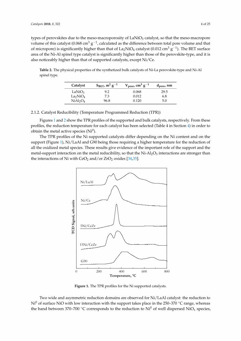


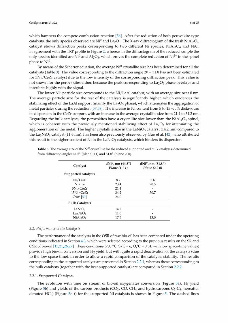


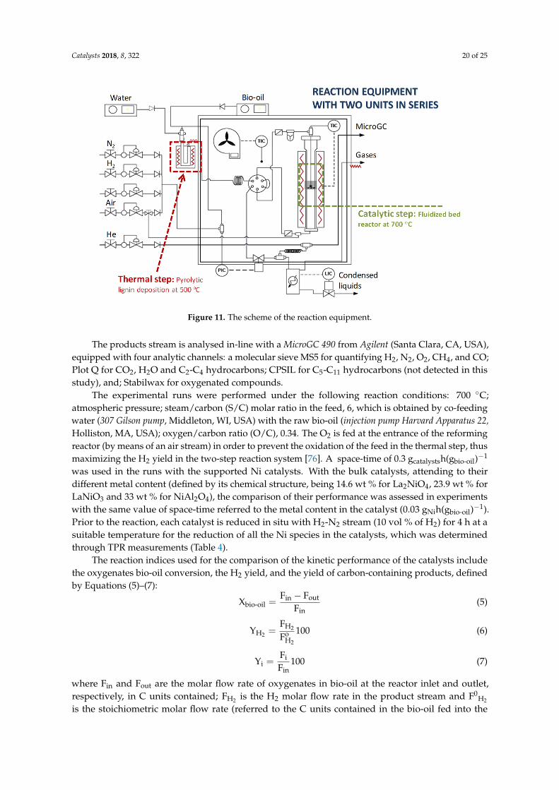


![Reforming and oxidative dehydrogenation of ethane with · PDF file4 . and catalyst deactivation. [2] Other reactions of CO 68 2 and ethane include oxidative dehydrogenation of 69 ethane](https://static.documents.pub/doc/80x56/5a78c98c7f8b9ae6228cf3f2/reforming-and-oxidative-dehydrogenation-of-ethane-with-and-catalyst-deactivation.jpg)


