22
Oxygen Steelmaking Introduction MATERIALS 3F03 MARCH 23, 2015
| Date post: | 18-Dec-2015 |
| Category: |
Documents |
| Upload: | duane-mason |
| View: | 217 times |
| Download: | 0 times |

Oxygen SteelmakingIntroduction
MATERIALS 3F03M A RC H 2 3 , 2 0 1 5

Hot Metal Chemistry
2
Figure Source: 2
Hot Metal is saturated in C, due to hearth conditions Hot metal in coke bed
Typical hot metal chemistry: 4.5 - 5.0 % C 0.3-1.0 % Si 0.1 – 0.7 % Mn 0.05-0.10 % S 0.01-0.08 % P
External desulphurization after BF is typical in industry
Carbon content of hot metal needs to be substantially lowered to create steel

Oxygen SteelmakingRefers to augeneous process for converting hot metal into steel: Top blown
LD (Linz-Donowitz)
BOF (Basic Oxygen Furnace) or BOS
Bottom Blown OBM, Q-BOP
Combined Blowing KOBM, LBE
4% C to less than 0.1 % C in ~16 minutes (~30 minutes total)
3
Figure Source: 1

Process Sequence
4
Figure Source: 1

BOF BlowUsually 16-25 minutes
Pure oxygen blown in a supersonic rates generates slag/metal emulsion for high reaction rate
~100% oxygen utilization
5
Figure Source: 1

Process ReactionsThere are three major stages in the BOF process:
1) Slag Formation 2) Constant Decarburization Rate 3) Carbon mass transfer control
6
Figure Source: 1

Slag FormationSoft blowing to start to make a SiO2-FeO rich slag (Fayalitic-type)
Once the slag is formed, harder blowing creates slag-metal emulsion
Oxidation at the end
7
Figure Source: 1

Mass and Energy BalanceMore heat generated from
C Oxidation Si Oxidation
Than required for:◦ Heating metal◦ Heating and melting slag
Coolants added: Scrap (70/30 hot metal ratio common in NA) Iron ore
8
Figure Source: 1

Mass and Energy Balance
9
Figure Source: 1

Bottom BlowingMost BOF vessels have some form of bottom stirring to improve mixing: C & O closer to equilibrium Better dephosphorization Quicker slag formation Less iron oxide in slag for better iron and
alloy yield
Looking at mixing times, a small amount of bottom gas is almost like total bottom flow LH is lance height QB and QT are bottom and top flow rates
10
Figure Source: 1

Bottom BlowingLower iron yield loss (as FeO in the steelmaking) associated with bottom blowing C & O closer to equilibrium More decarburization before entering
carbon mass transport control regime
11
Figure Source: 1

OS ReactionsOxygen is the driver for most reactions
Controlled by oxygen potential Involve oxygen directly
12
Figure Source: 1

OS ReactionsOxygen is the driver for most reactions
Controlled by oxygen potential Involve oxygen directly
13
Figure Source: 1

Oxidation of SiliconRate Controlled by mass transfer of silicon in metal: [Si] + 2(FeO) = (SiO2) + 2[Fe]
Shows first order behavior until Si content <0.05% Si
Silicon oxidation largely completely in early stages of the blow
14
Figure Source: 1
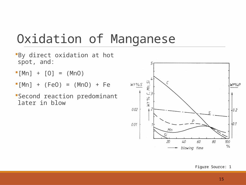
Oxidation of ManganeseBy direct oxidation at hot spot, and:
[Mn] + [O] = (MnO)
[Mn] + (FeO) = (MnO) + Fe
Second reaction predominant later in blow
15
Figure Source: 1
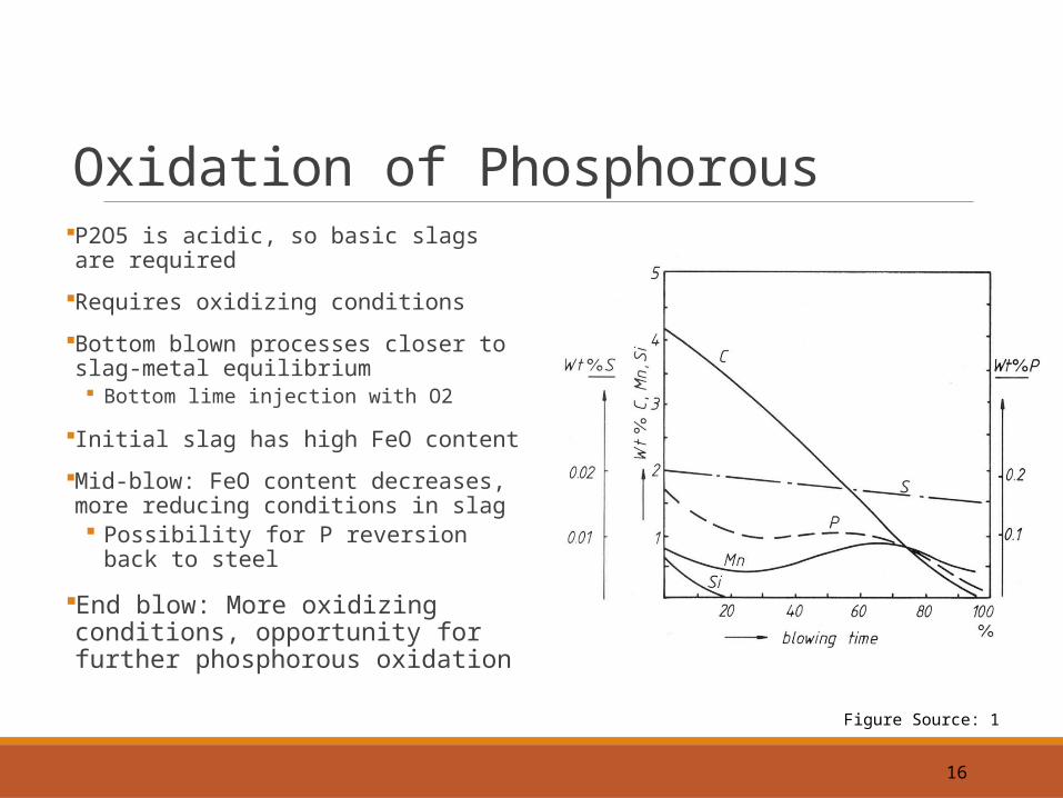
Oxidation of PhosphorousP2O5 is acidic, so basic slags are required
Requires oxidizing conditions
Bottom blown processes closer to slag-metal equilibrium Bottom lime injection with O2
Initial slag has high FeO content
Mid-blow: FeO content decreases, more reducing conditions in slag Possibility for P reversion back to steel
End blow: More oxidizing conditions, opportunity for further phosphorous oxidation
16
Figure Source: 1

Sulphur RemovalGenerally poor because of oxidizing conditions
S partition is worse with acidic slags
Better to maximize desulphurization in the BF, use external desulphurization facility
17
Figure Source: 1

Critical Carbon ContentOnce carbon mass transfer control regime commences: Supply of C to reaction sites is not
sufficient to consume O Oxygen dissolution in steel substantially
increases Oxidation of Fe increases, higher FeO
content in slag
Carbon content where constant decarburization regime ends is called Critical Carbon Content
18
Figure Source: 1
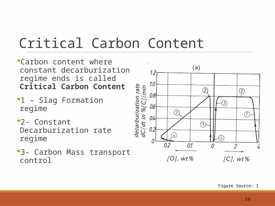
Critical Carbon ContentCarbon content where constant decarburization regime ends is called Critical Carbon Content
1 – Slag Formation regime
2- Constant Decarburization rate regime
3- Carbon Mass transport control
19
Figure Source: 1

Critical Carbon ContentCarbon content where constant decarburization regime ends is called Critical Carbon Content
Options to reduce critical carbon content: Slower oxygen blowing (productivity
impact)
20
Figure Source: 1

Critical Carbon ContentTo reduce carbon content lower than the critical carbon content means that higher yield loss of Fe to slag must be accepted Increased oxygen dissolution into
steel
Other options include vacuum processes for ultra-low carbon grades
Reminder: Bottom blowing practice means lower oxidation of metal for a given carbon content
21
Figure Source: 1

References 1 Bramha Deo and Rob Boom, Fundamentals of Steelmaking Metallurgy, Prentice Hall, 1993, Chapters 5.1-5.2 and 6.1-6.6
2 Geerdes et Al, Blast Furnace Ironmaking: An introduction, 2009
Much of the content is taken directly from or adapted from Materials 4C03 Oxygen Steelmaking slides prepared Dr. Gord Irons.


