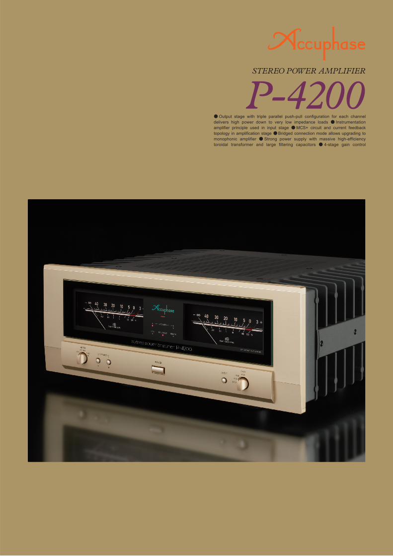
● Output stage with triple parallel push-pull configuration for each channel delivers high power down to very low impedance loads ● Instrumentation amplifier principle used in input stage ● MCS+ circuit and current feedback topology in amplification stage ● Bridged connection mode allows upgrading to monophonic amplifier ● Strong power supply with massive high-efficiency toroidal transformer and large filtering capacitors ● 4-stage gain control
Transcript
RIGHT + LEFT + RIGHT + LEFT +
Left speaker Left speakerRight speaker Right speaker
Preamplifier
RLRL
LOWHIGH
Input to left channel
Input to left channel
LOWHIGH
R L R L
Input to left channel
Input to left channel
e r yt u
!2i
!0 !3
q w
!1o
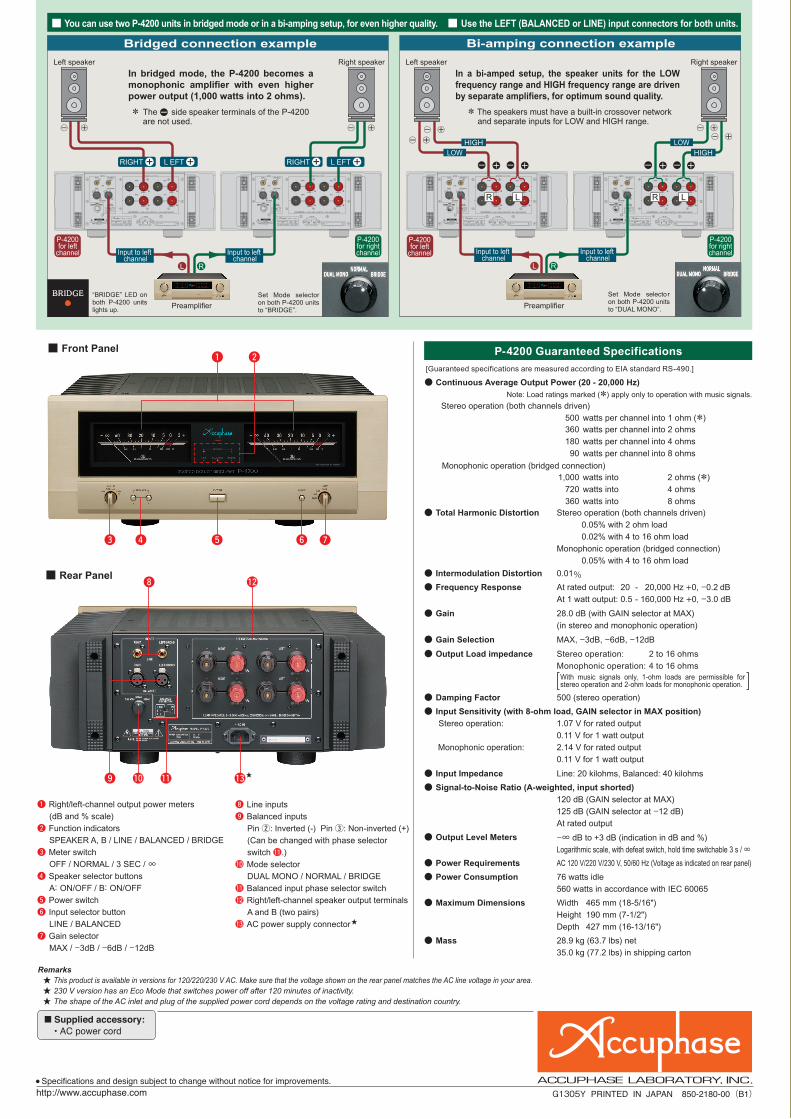
Front Panel
Rear Panel
Bi-amping connection exampleBridged connection example
Note: Load ratings marked (*) apply only to operation with music signals.
Stereo operation (both channels driven)
500 watts per channel into 1 ohm (*)
360 watts per channel into 2 ohms
180 watts per channel into 4 ohms
90 watts per channel into 8 ohms
Monophonic operation (bridged connection)
1,000 watts into
720 watts into
360 watts into
2 ohms (*)
4 ohms
8 ohms Total Harmonic Distortion Stereo operation (both channels driven)
0.05% with 2 ohm load
0.02% with 4 to 16 ohm load
Monophonic operation (bridged connection)
0.05% with 4 to 16 ohm load
Intermodulation Distortion 0.01% Frequency Response At rated output: 20 - 20,000 Hz +0, -0.2 dB
At 1 watt output: 0.5 - 160,000 Hz +0, -3.0 dB
Gain 28.0 dB (with GAIN selector at MAX)
(in stereo and monophonic operation)
Gain Selection MAX, -3dB, -6dB, -12dB
Output Load impedance Stereo operation: 2 to 16 ohms
Monophonic operation: 4 to 16 ohms
Damping Factor 500 (stereo operation)
Input Sensitivity (with 8-ohm load, GAIN selector in MAX position)
Stereo operation: 1.07 V for rated output
0.11 V for 1 watt output
Monophonic operation: 2.14 V for rated output
0.11 V for 1 watt output Input Impedance Line: 20 kilohms, Balanced: 40 kilohms
Signal-to-Noise Ratio (A-weighted, input shorted)
120 dB (GAIN selector at MAX)
125 dB (GAIN selector at -12 dB)
At rated output
Output Level Meters
-∞ dB to +3 dB (indication in dB and %)
Logarithmic scale, with defeat switch, hold time switchable 3 s / ∞ Power Requirements AC 120 V/220 V/230 V, 50/60 Hz (Voltage as indicated on rear panel)
Power Consumption 76 watts idle
560 watts in accordance with IEC 60065 Maximum Dimensions
Width 465 mm (18-5/16")
Height 190 mm (7-1/2")
Depth 427 mm (16-13/16")
Mass
28.9 kg (63.7 lbs) net
35.0 kg (77.2 lbs) in shipping carton
P-4200 Guaranteed Specifications
i Line inputs
o Balanced inputs
Pin w: Inverted (-) Pin e: Non-inverted (+)
(Can be changed with phase selector
switch !1.)
!0 Mode selector
DUAL MONO / NORMAL / BRIDGE
!1 Balanced input phase selector switch
!2 Right/left-channel speaker output terminals A and B (two pairs)
!3 AC power supply connector
In bridged mode, the P-4200 becomes a monophonic amplifier with even higher power output (1,000 watts into 2 ohms).
P-4200 for left
channel
P-4200 for left
channel
P-4200 for right channel
P-4200 for right channel
Set Mode selector on both P-4200 units to “DUAL MONO”.Preamplifier
* The side speaker terminals of the P-4200 are not used.
In a bi-amped setup, the speaker units for the LOW frequency range and HIGH frequency range are driven by separate amplifiers, for optimum sound quality.
[Guaranteed specifications are measured according to EIA standard RS-490.]
Output stage with triple parallel push-pull configuration for each channel delivers high power down to very low impedance loads Instrumentation amplifier principle used in input stage MCS+ circuit and current feedback topology in amplification stage Bridged connection mode allows upgrading to monophonic amplifier Strong power supply with massive high-efficiency toroidal transformer and large filtering capacitors 4-stage gain control
* The speakers must have a built-in crossover network and separate inputs for LOW and HIGH range.
Set Mode selector on both P-4200 units to “BRIDGE”.
Continuous Average Output Power (20 - 20,000 Hz)
You can use two P-4200 units in bridged mode or in a bi-amping setup, for even higher quality. Use the LEFT (BALANCED or LINE) input connectors for both units.
“BRIDGE” LED on both P-4200 units lights up.
q Right/left-channel output power meters
(dB and % scale)
w Function indicators
SPEAKER A, B / LINE / BALANCED / BRIDGE
e Meter switch
OFF / NORMAL / 3 SEC / ∞r Speaker selector buttons
A: ON/OFF / B: ON/OFF
t Power switch
y Input selector button
LINE / BALANCED
u Gain selector
MAX / -3dB / -6dB / -12dB
With music signals only, 1-ohm loads are permissible for stereo operation and 2-ohm loads for monophonic operation.
Supplied accessory:• AC power cord
Specifications and design subject to change without notice for improvements.G1305Y PRINTED IN JAPAN 850-2180-00(B1)
Remarks This product is available in versions for 120/220/230 V AC. Make sure that the voltage shown on the rear panel matches the AC line voltage in your area. 230 V version has an Eco Mode that switches power off after 120 minutes of inactivity. The shape of the AC inlet and plug of the supplied power cord depends on the voltage rating and destination country.
http://www.accuphase.com
マゼンダはDIC-160 シアンは指定色(A-200と同じ)
OUTPUT
I/Vconverter
Trans-impedance amplifier
Current adder
– INPUT
+ INPUT
Current NFB network
Buffer
Buffer
OUTPUT
Amplifier
– INPUT
OUTPUT
+ INPUT
+
–
+
–
–
+
NFBNETWORK
NFBNETWORK
NFBNETWORK
Power amplifier stageSignal input stage
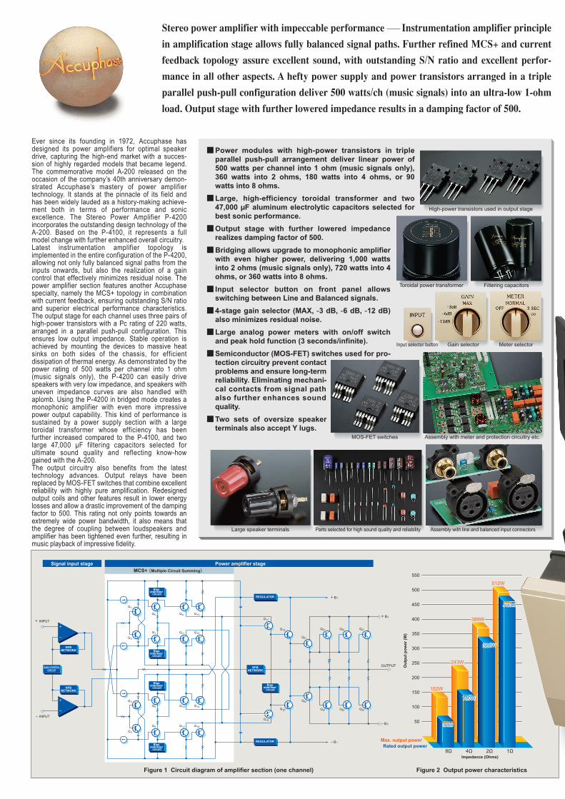
512W
90W90W
8Ω 4Ω 2Ω 1Ω
180W180W
360W360W
500W500W
152W
243W
389W
Max. output power
50
100
150
200
250
300
350
400
450
500
550
Impedance (Ohms)
Rated output power
+ INPUT
+ B1
B1
Q1
Q3
Q2
Q4
Q8
Q6
Q7
Q5 Q9
Q17
Q19
Q21
Q18
Q20
Q22
Q13
Q11 Q15
Q10 Q14
Q12 Q16
INPUT
B2
Bias stabilizer
circuit
NFBNETWORK
NFBNETWORK
NFBNETWORK
GAIN CONTROLCIRCUIT
REGULATOR
REGULATOR
-
+
Power amplifier stageMCS+ (Multiple Circuit Summing)
Signal input stage
Q23 Q25 Q27
Q24 Q26 Q28
+ B2
-
+
Bias stabilizer
circuit
Bias stabilizer
circuitBias
stabilizer circuit
Bias stabilizer
circuit
Ou
tpu
t p
ow
er (
W)
Figure 1 Circuit diagram of amplifier section (one channel)
Principle of current feedback amplifier
Figure 2 Output power characteristics
Instrumentation amplifier configuration
Parts selected for high sound quality and reliability
MOS-FET switches
Assembly with line and balanced input connectors
High-power transistors used in output stage
Filtering capacitorsToroidal power transformer
Large speaker terminals
Assembly with meter and protection circuitry etc.
Gain selector Meter selectorInput selector button
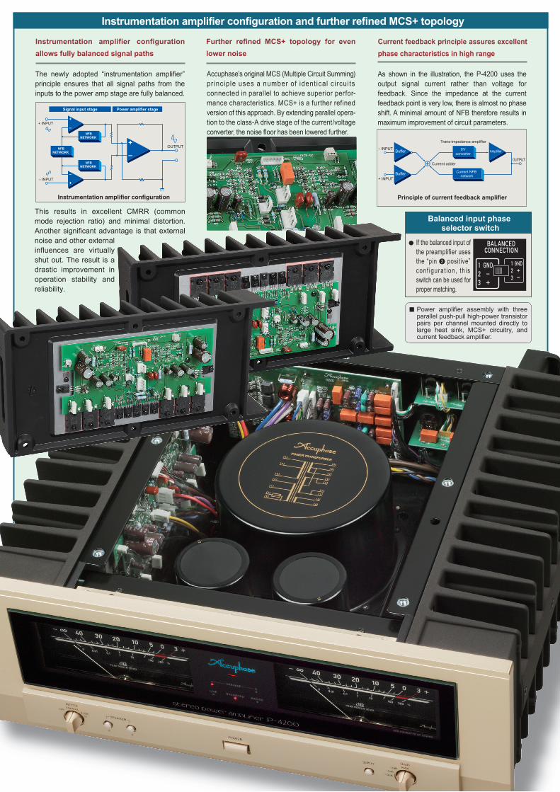
Power amplifier assembly with three parallel push-pull high-power transistor pairs per channel mounted directly to large heat sink, MCS+ circuitry, and current feedback amplifier.
Instrumentation amplifier configuration and further refined MCS+ topology
Balanced input phase selector switch
If the balanced input of the preamplifier uses the “pin w positive” conf igura t ion , th is switch can be used for proper matching.
Accuphase’s original MCS (Multiple Circuit Summing) pr inciple uses a number of ident ical c ircuits connected in parallel to achieve superior perfor-mance characteristics. MCS+ is a further refined version of this approach. By extending parallel opera-tion to the class-A drive stage of the current/voltage converter, the noise floor has been lowered further.
Further refined MCS+ topology for even
lower noise
Current feedback principle assures excellent
phase characteristics in high range
Instrumentation amplifier configuration
allows fully balanced signal paths
As shown in the illustration, the P-4200 uses the output signal current rather than voltage for feedback. Since the impedance at the current feedback point is very low, there is almost no phase shift. A minimal amount of NFB therefore results in maximum improvement of circuit parameters.
The newly adopted “instrumentation amplifier” principle ensures that all signal paths from the inputs to the power amp stage are fully balanced.
This results in excellent CMRR (common mode rejection ratio) and minimal distortion. Another significant advantage is that external noise and other external influences are virtually shut out. The result is a drastic improvement in operation stability and reliability.
Ever since its founding in 1972, Accuphase has designed its power amplifiers for optimal speaker drive, capturing the high-end market with a succes-sion of highly regarded models that became legend. The commemorative model A-200 released on the occasion of the company’s 40th anniversary demon-strated Accuphase’s mastery of power amplifier technology. It stands at the pinnacle of its field and has been widely lauded as a history-making achieve-ment both in terms of performance and sonic excellence. The Stereo Power Amplifier P-4200 incorporates the outstanding design technology of the A-200. Based on the P-4100, it represents a full model change with further enhanced overall circuitry.Latest instrumentation amplifier topology is implemented in the entire configuration of the P-4200, allowing not only fully balanced signal paths from the inputs onwards, but also the realization of a gain control that effectively minimizes residual noise. The power amplifier section features another Accuphase specialty, namely the MCS+ topology in combination with current feedback, ensuring outstanding S/N ratio and superior electrical performance characteristics. The output stage for each channel uses three pairs of high-power transistors with a Pc rating of 220 watts, arranged in a parallel push-pull configuration. This ensures low output impedance. Stable operation is achieved by mounting the devices to massive heat sinks on both sides of the chassis, for efficient dissipation of thermal energy. As demonstrated by the power rating of 500 watts per channel into 1 ohm (music signals only), the P-4200 can easily drive speakers with very low impedance, and speakers with uneven impedance curves are also handled with aplomb. Using the P-4200 in bridged mode creates a monophonic amplifier with even more impressive power output capability. This kind of performance is sustained by a power supply section with a large toroidal transformer whose efficiency has been further increased compared to the P-4100, and two large 47,000 µF filtering capacitors selected for ultimate sound quality and reflecting know-how gained with the A-200.The output circuitry also benefits from the latest technology advances. Output relays have been replaced by MOS-FET switches that combine excellent reliability with highly pure amplification. Redesigned output coils and other features result in lower energy losses and allow a drastic improvement of the damping factor to 500. This rating not only points towards an extremely wide power bandwidth, it also means that the degree of coupling between loudspeakers and amplifier has been tightened even further, resulting in music playback of impressive fidelity.
Stereo power amplifier with impeccable performance Instrumentation amplifier principle in amplification stage allows fully balanced signal paths. Further refined MCS+ and current feedback topology assure excellent sound, with outstanding S/N ratio and excellent perfor-mance in all other aspects. A hefty power supply and power transistors arranged in a triple parallel push-pull configuration deliver 500 watts/ch (music signals) into an ultra-low 1-ohm load. Output stage with further lowered impedance results in a damping factor of 500.
Power modules with high-power transistors in triple parallel push-pull arrangement deliver linear power of 500 watts per channel into 1 ohm (music signals only), 360 watts into 2 ohms, 180 watts into 4 ohms, or 90 watts into 8 ohms.
Large, high-efficiency toroidal transformer and two 47,000 µF aluminum electrolytic capacitors selected for best sonic performance.
Output stage with further lowered impedance realizes damping factor of 500.
Bridging allows upgrade to monophonic amplifier with even higher power, delivering 1,000 watts into 2 ohms (music signals only), 720 watts into 4 ohms, or 360 watts into 8 ohms.
Input selector button on front panel allows switching between Line and Balanced signals.
4-stage gain selector (MAX, -3 dB, -6 dB, -12 dB) also minimizes residual noise.
Large analog power meters with on/off switch and peak hold function (3 seconds/infinite).
Semiconductor (MOS-FET) switches used for pro-tection circuitry prevent contact problems and ensure long-term reliability. Eliminating mechani-cal contacts from signal path also further enhances sound quality.
Two sets of oversize speaker terminals also accept Y lugs.
OUTPUT
I/Vconverter
Trans-impedance amplifier
Current adder
– INPUT
+ INPUT
Current NFB network
Buffer
Buffer
OUTPUT
Amplifier
– INPUT
OUTPUT
+ INPUT
+
–
+
–
–
+
NFBNETWORK
NFBNETWORK
NFBNETWORK
Power amplifier stageSignal input stage
512W
90W90W
8Ω 4Ω 2Ω 1Ω
180W180W
360W360W
500W500W
152W
243W
389W
Max. output power
50
100
150
200
250
300
350
400
450
500
550
Impedance (Ohms)
Rated output power
+ INPUT
+ B1
B1
Q1
Q3
Q2
Q4
Q8
Q6
Q7
Q5 Q9
Q17
Q19
Q21
Q18
Q20
Q22
Q13
Q11 Q15
Q10 Q14
Q12 Q16
INPUT
B2
Bias stabilizer
circuit
NFBNETWORK
NFBNETWORK
NFBNETWORK
GAIN CONTROLCIRCUIT
REGULATOR
REGULATOR
-
+
Power amplifier stageMCS+ (Multiple Circuit Summing)
Signal input stage
Q23 Q25 Q27
Q24 Q26 Q28
+ B2
-
+
Bias stabilizer
circuit
Bias stabilizer
circuitBias
stabilizer circuit
Bias stabilizer
circuit
Ou
tpu
t p
ow
er (
W)
Figure 1 Circuit diagram of amplifier section (one channel)
Principle of current feedback amplifier
Figure 2 Output power characteristics
Instrumentation amplifier configuration
Parts selected for high sound quality and reliability
MOS-FET switches
Assembly with line and balanced input connectors
High-power transistors used in output stage
Filtering capacitorsToroidal power transformer
Large speaker terminals
Assembly with meter and protection circuitry etc.
Gain selector Meter selectorInput selector button
Power amplifier assembly with three parallel push-pull high-power transistor pairs per channel mounted directly to large heat sink, MCS+ circuitry, and current feedback amplifier.
Instrumentation amplifier configuration and further refined MCS+ topology
Balanced input phase selector switch
If the balanced input of the preamplifier uses the “pin w positive” conf igura t ion , th is switch can be used for proper matching.
Accuphase’s original MCS (Multiple Circuit Summing) pr inciple uses a number of ident ical c ircuits connected in parallel to achieve superior perfor-mance characteristics. MCS+ is a further refined version of this approach. By extending parallel opera-tion to the class-A drive stage of the current/voltage converter, the noise floor has been lowered further.
Further refined MCS+ topology for even
lower noise
Current feedback principle assures excellent
phase characteristics in high range
Instrumentation amplifier configuration
allows fully balanced signal paths
As shown in the illustration, the P-4200 uses the output signal current rather than voltage for feedback. Since the impedance at the current feedback point is very low, there is almost no phase shift. A minimal amount of NFB therefore results in maximum improvement of circuit parameters.
The newly adopted “instrumentation amplifier” principle ensures that all signal paths from the inputs to the power amp stage are fully balanced.
This results in excellent CMRR (common mode rejection ratio) and minimal distortion. Another significant advantage is that external noise and other external influences are virtually shut out. The result is a drastic improvement in operation stability and reliability.
Ever since its founding in 1972, Accuphase has designed its power amplifiers for optimal speaker drive, capturing the high-end market with a succes-sion of highly regarded models that became legend. The commemorative model A-200 released on the occasion of the company’s 40th anniversary demon-strated Accuphase’s mastery of power amplifier technology. It stands at the pinnacle of its field and has been widely lauded as a history-making achieve-ment both in terms of performance and sonic excellence. The Stereo Power Amplifier P-4200 incorporates the outstanding design technology of the A-200. Based on the P-4100, it represents a full model change with further enhanced overall circuitry.Latest instrumentation amplifier topology is implemented in the entire configuration of the P-4200, allowing not only fully balanced signal paths from the inputs onwards, but also the realization of a gain control that effectively minimizes residual noise. The power amplifier section features another Accuphase specialty, namely the MCS+ topology in combination with current feedback, ensuring outstanding S/N ratio and superior electrical performance characteristics. The output stage for each channel uses three pairs of high-power transistors with a Pc rating of 220 watts, arranged in a parallel push-pull configuration. This ensures low output impedance. Stable operation is achieved by mounting the devices to massive heat sinks on both sides of the chassis, for efficient dissipation of thermal energy. As demonstrated by the power rating of 500 watts per channel into 1 ohm (music signals only), the P-4200 can easily drive speakers with very low impedance, and speakers with uneven impedance curves are also handled with aplomb. Using the P-4200 in bridged mode creates a monophonic amplifier with even more impressive power output capability. This kind of performance is sustained by a power supply section with a large toroidal transformer whose efficiency has been further increased compared to the P-4100, and two large 47,000 µF filtering capacitors selected for ultimate sound quality and reflecting know-how gained with the A-200.The output circuitry also benefits from the latest technology advances. Output relays have been replaced by MOS-FET switches that combine excellent reliability with highly pure amplification. Redesigned output coils and other features result in lower energy losses and allow a drastic improvement of the damping factor to 500. This rating not only points towards an extremely wide power bandwidth, it also means that the degree of coupling between loudspeakers and amplifier has been tightened even further, resulting in music playback of impressive fidelity.
Stereo power amplifier with impeccable performance Instrumentation amplifier principle in amplification stage allows fully balanced signal paths. Further refined MCS+ and current feedback topology assure excellent sound, with outstanding S/N ratio and excellent perfor-mance in all other aspects. A hefty power supply and power transistors arranged in a triple parallel push-pull configuration deliver 500 watts/ch (music signals) into an ultra-low 1-ohm load. Output stage with further lowered impedance results in a damping factor of 500.
Power modules with high-power transistors in triple parallel push-pull arrangement deliver linear power of 500 watts per channel into 1 ohm (music signals only), 360 watts into 2 ohms, 180 watts into 4 ohms, or 90 watts into 8 ohms.
Large, high-efficiency toroidal transformer and two 47,000 µF aluminum electrolytic capacitors selected for best sonic performance.
Output stage with further lowered impedance realizes damping factor of 500.
Bridging allows upgrade to monophonic amplifier with even higher power, delivering 1,000 watts into 2 ohms (music signals only), 720 watts into 4 ohms, or 360 watts into 8 ohms.
Input selector button on front panel allows switching between Line and Balanced signals.
4-stage gain selector (MAX, -3 dB, -6 dB, -12 dB) also minimizes residual noise.
Large analog power meters with on/off switch and peak hold function (3 seconds/infinite).
Semiconductor (MOS-FET) switches used for pro-tection circuitry prevent contact problems and ensure long-term reliability. Eliminating mechani-cal contacts from signal path also further enhances sound quality.
Two sets of oversize speaker terminals also accept Y lugs.
RIGHT + LEFT + RIGHT + LEFT +
Left speaker Left speakerRight speaker Right speaker
Preamplifier
RLRL
LOWHIGH
Input to left channel
Input to left channel
LOWHIGH
R L R L
Input to left channel
Input to left channel
e r yt u
!2i
!0 !3
q w
!1o
Front Panel
Rear Panel
Bi-amping connection exampleBridged connection example
Note: Load ratings marked (*) apply only to operation with music signals.
Stereo operation (both channels driven)
500 watts per channel into 1 ohm (*)
360 watts per channel into 2 ohms
180 watts per channel into 4 ohms
90 watts per channel into 8 ohms
Monophonic operation (bridged connection)
1,000 watts into
720 watts into
360 watts into
2 ohms (*)
4 ohms
8 ohms Total Harmonic Distortion Stereo operation (both channels driven)
0.05% with 2 ohm load
0.02% with 4 to 16 ohm load
Monophonic operation (bridged connection)
0.05% with 4 to 16 ohm load
Intermodulation Distortion 0.01% Frequency Response At rated output: 20 - 20,000 Hz +0, -0.2 dB
At 1 watt output: 0.5 - 160,000 Hz +0, -3.0 dB
Gain 28.0 dB (with GAIN selector at MAX)
(in stereo and monophonic operation)
Gain Selection MAX, -3dB, -6dB, -12dB
Output Load impedance Stereo operation: 2 to 16 ohms
Monophonic operation: 4 to 16 ohms
Damping Factor 500 (stereo operation)
Input Sensitivity (with 8-ohm load, GAIN selector in MAX position)
Stereo operation: 1.07 V for rated output
0.11 V for 1 watt output
Monophonic operation: 2.14 V for rated output
0.11 V for 1 watt output Input Impedance Line: 20 kilohms, Balanced: 40 kilohms
Signal-to-Noise Ratio (A-weighted, input shorted)
120 dB (GAIN selector at MAX)
125 dB (GAIN selector at -12 dB)
At rated output
Output Level Meters
-∞ dB to +3 dB (indication in dB and %)
Logarithmic scale, with defeat switch, hold time switchable 3 s / ∞ Power Requirements AC 120 V/220 V/230 V, 50/60 Hz (Voltage as indicated on rear panel)
Power Consumption 76 watts idle
560 watts in accordance with IEC 60065 Maximum Dimensions
Width 465 mm (18-5/16")
Height 190 mm (7-1/2")
Depth 427 mm (16-13/16")
Mass
28.9 kg (63.7 lbs) net
35.0 kg (77.2 lbs) in shipping carton
P-4200 Guaranteed Specifications
i Line inputs
o Balanced inputs
Pin w: Inverted (-) Pin e: Non-inverted (+)
(Can be changed with phase selector
switch !1.)
!0 Mode selector
DUAL MONO / NORMAL / BRIDGE
!1 Balanced input phase selector switch
!2 Right/left-channel speaker output terminals A and B (two pairs)
!3 AC power supply connector
In bridged mode, the P-4200 becomes a monophonic amplifier with even higher power output (1,000 watts into 2 ohms).
P-4200 for left
channel
P-4200 for left
channel
P-4200 for right channel
P-4200 for right channel
Set Mode selector on both P-4200 units to “DUAL MONO”.Preamplifier
* The side speaker terminals of the P-4200 are not used.
In a bi-amped setup, the speaker units for the LOW frequency range and HIGH frequency range are driven by separate amplifiers, for optimum sound quality.
[Guaranteed specifications are measured according to EIA standard RS-490.]
Output stage with triple parallel push-pull configuration for each channel delivers high power down to very low impedance loads Instrumentation amplifier principle used in input stage MCS+ circuit and current feedback topology in amplification stage Bridged connection mode allows upgrading to monophonic amplifier Strong power supply with massive high-efficiency toroidal transformer and large filtering capacitors 4-stage gain control
* The speakers must have a built-in crossover network and separate inputs for LOW and HIGH range.
Set Mode selector on both P-4200 units to “BRIDGE”.
Continuous Average Output Power (20 - 20,000 Hz)
You can use two P-4200 units in bridged mode or in a bi-amping setup, for even higher quality. Use the LEFT (BALANCED or LINE) input connectors for both units.
“BRIDGE” LED on both P-4200 units lights up.
q Right/left-channel output power meters
(dB and % scale)
w Function indicators
SPEAKER A, B / LINE / BALANCED / BRIDGE
e Meter switch
OFF / NORMAL / 3 SEC / ∞r Speaker selector buttons
A: ON/OFF / B: ON/OFF
t Power switch
y Input selector button
LINE / BALANCED
u Gain selector
MAX / -3dB / -6dB / -12dB
With music signals only, 1-ohm loads are permissible for stereo operation and 2-ohm loads for monophonic operation.
Supplied accessory:• AC power cord
Specifications and design subject to change without notice for improvements.G1305Y PRINTED IN JAPAN 850-2180-00(B1)
Remarks This product is available in versions for 120/220/230 V AC. Make sure that the voltage shown on the rear panel matches the AC line voltage in your area. 230 V version has an Eco Mode that switches power off after 120 minutes of inactivity. The shape of the AC inlet and plug of the supplied power cord depends on the voltage rating and destination country.