An RC aircraft is not a toy! If misused, it can cause serious bodily harm and damage to property. Fly only in open areas, preferably at AMA (Academy of Model Aeronautics) approved flying sites, following all instructions included with your radio and engine.
Additional Required Tools and Adhesives
Warning
5
Before beginning the assembly of your P-51 Mustang PTS, remove each part from its bag for inspection. Closely inspect the fuselage, wing panels, rudder and stabilizer for damage. If you find any damaged or missing parts, contact the place of purchase.
If you find any wrinkles in the covering, use a heat gun or covering iron to remove them. Use caution while working around areas where the colors overlap to prevent separating the colors.
This manual is divided into sections to help make assembly easier to understand, and to provide breaks between each major section. Remember to take your time and follow the directions.
Horizon Hobby, Inc. guarantees this kit to be free from defects in both material and workmanship at the date of purchase. This warranty does not cover any parts damaged by use or modification. In no case shall Horizon Hobby’s liability exceed the original cost of the purchased kit. Further, Horizon Hobby reserves the right to change or modify this warranty without notice.In that Horizon Hobby has no control over the final assembly or material used for the final assembly, no liability shall be assumed nor accepted for any damage of the final user-assembled product. By the act of using the product, the user accepts all resulting liability.Once assembly of the model has been started, you must contact Horizon Hobby, Inc. directly regarding any warranty question that you have. Please do not contact your local hobby shop regarding warranty issues, even if that is where you purchased it. This will enable Horizon to better answer your questions and provide service in the event that you may need any assistance.If the buyer is not prepared to accept the liability associated with the use of this product, the buyer is advised to return this kit immediately in new and unused condition to the place of purchase.
Horizon Hobby Service Department4105 Fieldstone Road
Champaign, Illinois 61822(217) 355-9511
horizonhobby.com
HAN100 – Heat Gun
HAN150 – Covering Glove
HAN101 – Covering Iron
HAN141 – Sealing Iron Sock
Before Starting Assembly
Using the Manual
Warranty Information
6
Before starting the assembly of your P-51 Mustang PTS, open the radio box and read the included instructions. Directions on the features, specifications, controls, functions, charging, and other useful information is contained in this manual.To charge the radio, you will need to remove the charger and follow the radio instructions. The charge lead for the receiver battery is located in the fuselage of your P-51 Mustang PTS, and has two wires. The charger will connect to this lead as shown.
Note: There are two other leads that are for the aileron servos to plug into. The charger should not be connected to these plugs.
Section 1: Charging the Batteries
7
Items required:• Left wing panel • Right wing panel• Aluminum wing tube • Nylon strap• #4 x 1/2" wood screw (2)
Step 1Locate the aluminum wing tube. Slide the tube into one of the wing panels. Do not force the tube, as it will slide easily to its correct depth.
Step 2Slide the remaining wing panel onto the aluminum wing joiner tube. As the panels get close, make sure the alignment pin goes into the hole.
Step 3Slide the panels tightly together, guiding the servo wires out of the way. Use a nylon strap and two #4 x 1/2" sheet metal screws to secure the two wing panels together.
Step 4If you are not planning on taking your wing apart, a piece of covering has been supplied to cover the center joint. You will need to use a covering iron to apply the covering to the center joint.
Section 2: Assembling the Wing
8
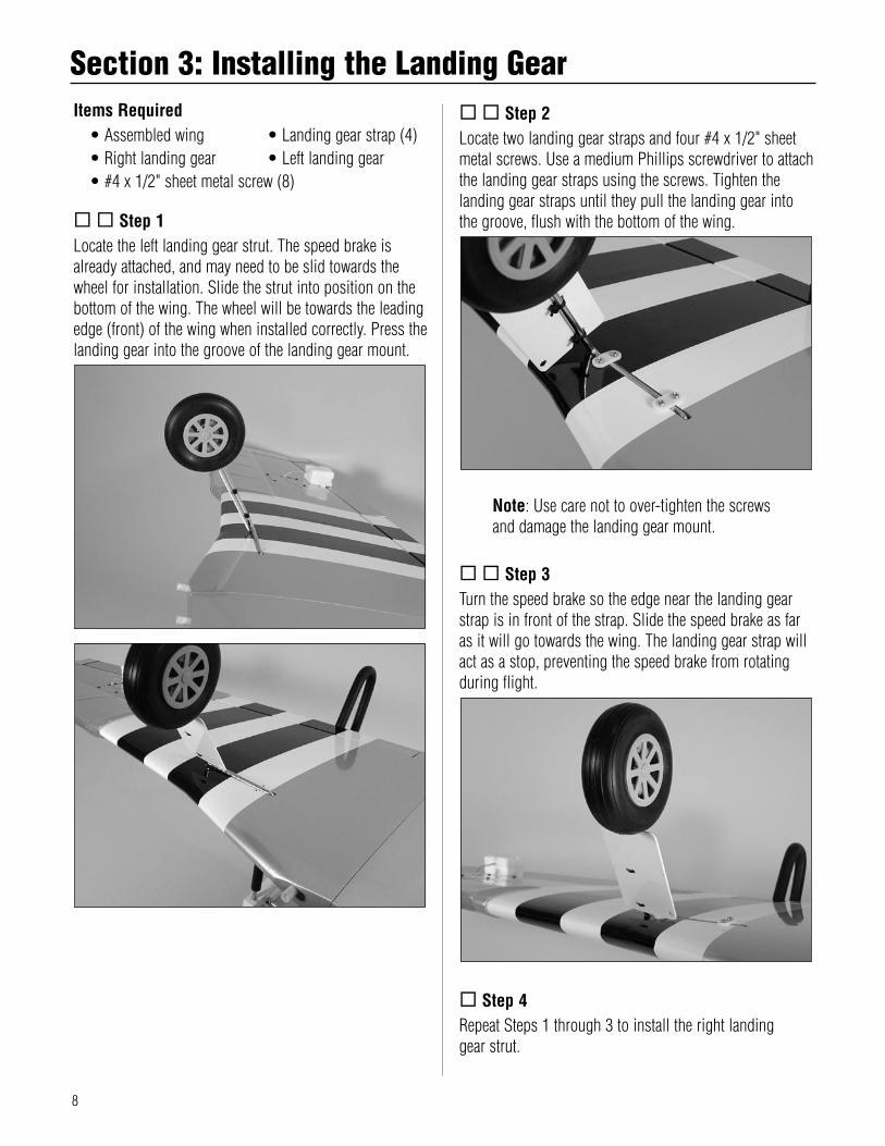
Items Required• Assembled wing • Landing gear strap (4)• Right landing gear • Left landing gear• #4 x 1/2" sheet metal screw (8)
Step 1Locate the left landing gear strut. The speed brake is already attached, and may need to be slid towards the wheel for installation. Slide the strut into position on the bottom of the wing. The wheel will be towards the leading edge (front) of the wing when installed correctly. Press the landing gear into the groove of the landing gear mount.
Step 2Locate two landing gear straps and four #4 x 1/2" sheet metal screws. Use a medium Phillips screwdriver to attach the landing gear straps using the screws. Tighten the landing gear straps until they pull the landing gear into the groove, flush with the bottom of the wing.
Note: Use care not to over-tighten the screws and damage the landing gear mount.
Step 3Turn the speed brake so the edge near the landing gear strap is in front of the strap. Slide the speed brake as far as it will go towards the wing. The landing gear strap will act as a stop, preventing the speed brake from rotating during flight.
Step 4Repeat Steps 1 through 3 to install the right landing gear strut.
Section 3: Installing the Landing Gear
9
Items Requires• Fuselage • Stabilizer/elevator• Threadlock• Pliers or adjustable wrench
Step 1Loosen the nuts on the bottom of the fuselage that are holding the rudder/fin assembly onto the fuselage. Pull the rudder/fin assembly straight up to remove them from the fuselage. Use care not to damage the lower portion of the fin or the fuselage fairing.
Step 2Locate the stabilizer/elevator assembly. Position the stabilizer/elevator assembly so the control horn will face down, away from the fin. The threaded rods from the rudder/fin assembly will slide into the two holes in the stabilizer. The fuselage fairing has been slid into position on the fin in the photograph.
Step 3Apply a drop or two of threadlock to the exposed threads of the threaded rods. Thread the nuts onto the rod, tightening them snugly against the bottom of the fuselage using pliers or an adjustable wrench. Do not over-tighten the nuts.
Section 4: Installing the Tail Surfaces
10
Items required• Fuselage • Propeller• Spinner• #4 x 5/8" sheet metal socket head screw (3)• Exhaust stack, right and left• #2 x 5/16" wood screw (4)• Adjustable wrench
Step 1Remove the propeller nut and washer from the engine.
Step 2Slide the spinner backplate onto the engine shaft, and then slide the propeller into position.
Step 3Slide the washer and thread the nut onto the engine shaft. Rotate the propeller clockwise so it is resting against the lugs of the spinner backplate. Use an adjustable wrench to tighten the propeller nut. Do not use pliers, as the nut will not be tight enough, and could come loose.
Note: It is suggested to read the engine instructions included with your P-51 Mustang PTS at this time to learn more on the care and operation of your Evolution engine.
Section 5: Installing the Propeller
11
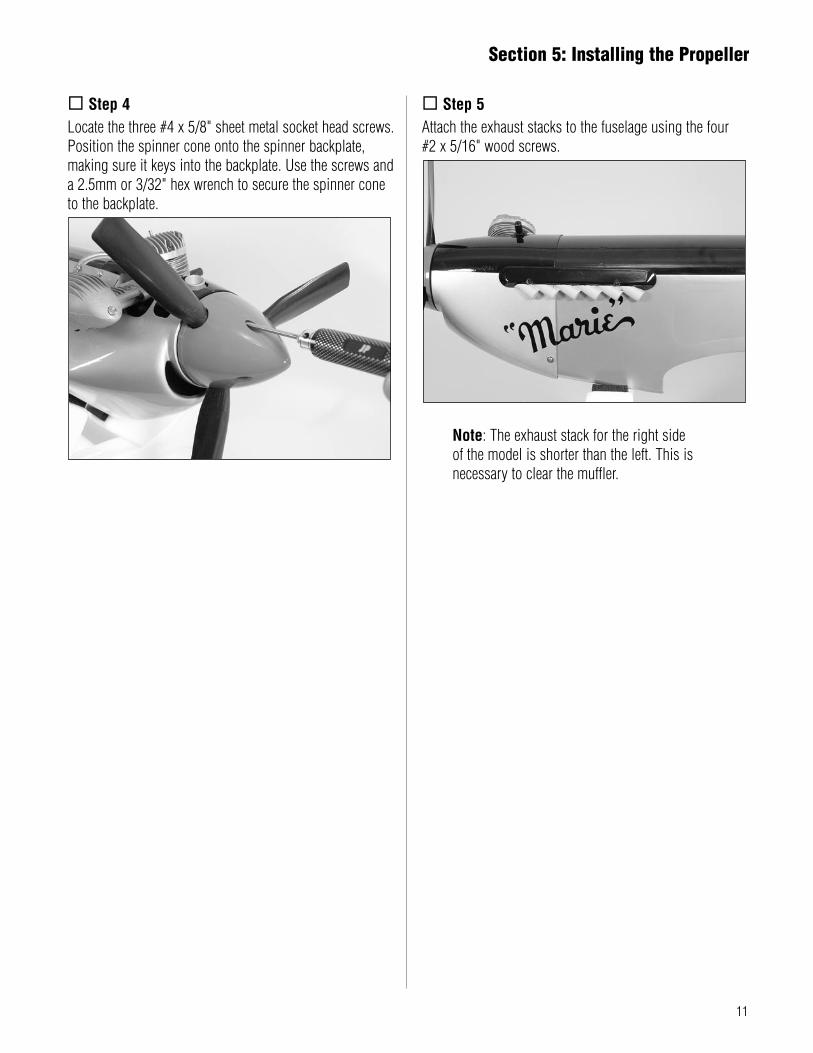
Step 4Locate the three #4 x 5/8" sheet metal socket head screws. Position the spinner cone onto the spinner backplate, making sure it keys into the backplate. Use the screws and a 2.5mm or 3/32" hex wrench to secure the spinner cone to the backplate.
Step 5Attach the exhaust stacks to the fuselage using the four #2 x 5/16" wood screws.
Note: The exhaust stack for the right side of the model is shorter than the left. This is necessary to clear the muffler.
Section 5: Installing the Propeller
12
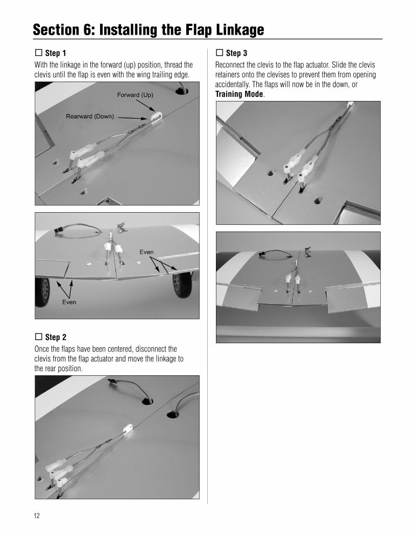
Step 1With the linkage in the forward (up) position, thread the clevis until the flap is even with the wing trailing edge.
Step 2Once the flaps have been centered, disconnect the clevis from the flap actuator and move the linkage to the rear position.
Step 3Reconnect the clevis to the flap actuator. Slide the clevis retainers onto the clevises to prevent them from opening accidentally. The flaps will now be in the down, or Training Mode.
Step 1Locate the servo leads from the wing and plug them into the leads for the ailerons located in the fuselage. These leads are identical, so you can plug either of the aileron servo leads into either of the extensions.
Step 2Guide the wing dowels at the front of the wing into the holes located in the fuselage. Allow the wing to drop down and rest in the wing saddle of the fuselage.
Note: Check to make sure the servo leads are inside the fuselage and not caught between the wing and fuselage.
Step 3Locate the two 1/4-20 x 2" nylon wing bolts. Slide the bolts into the holes in the radiator scoop so the threads are exposed.
Step 4Place the radiator scoop onto the wing, guiding the bolts into the bolt holes in the wing. Use a flat blade screwdriver to tighten bolts, securing the wing to the fuselage. It is helpful to pull the back of the wing away from the fuselage so you can guide the bolts into the holes in the fuselage to start them threading into the holes.
Section 7: Attaching the Wing
14
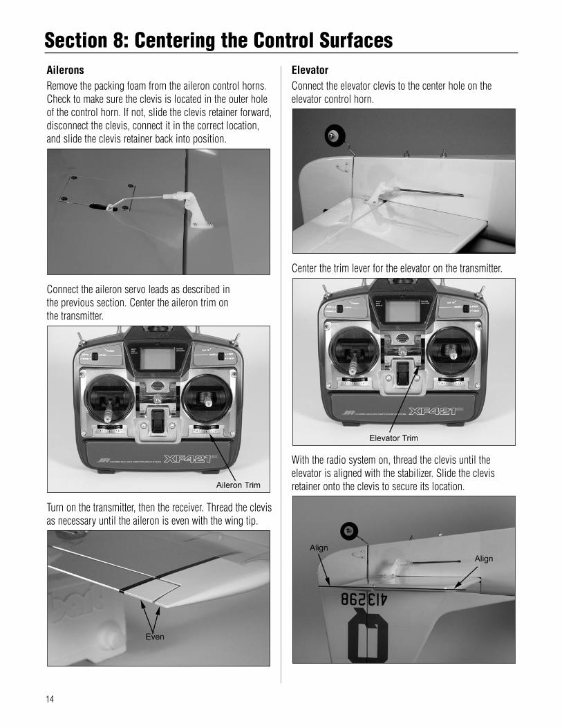
AileronsRemove the packing foam from the aileron control horns. Check to make sure the clevis is located in the outer hole of the control horn. If not, slide the clevis retainer forward, disconnect the clevis, connect it in the correct location, and slide the clevis retainer back into position.
Connect the aileron servo leads as described in the previous section. Center the aileron trim on the transmitter.
Turn on the transmitter, then the receiver. Thread the clevis as necessary until the aileron is even with the wing tip.
ElevatorConnect the elevator clevis to the center hole on the elevator control horn.
Center the trim lever for the elevator on the transmitter.
With the radio system on, thread the clevis until the elevator is aligned with the stabilizer. Slide the clevis retainer onto the clevis to secure its location.
Section 8: Centering the Control Surfaces
15
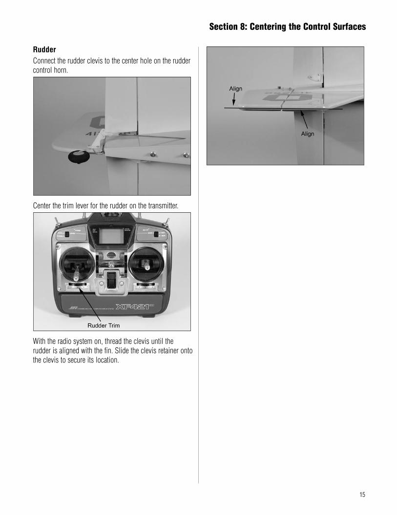
RudderConnect the rudder clevis to the center hole on the rudder control horn.
Center the trim lever for the rudder on the transmitter.
With the radio system on, thread the clevis until the rudder is aligned with the fin. Slide the clevis retainer onto the clevis to secure its location.
Section 8: Centering the Control Surfaces
16
AileronsTurn on the transmitter, then the receiver. Move the aileron stick to the right, which is the input for a right turn. The right aileron will move up, and the left aileron will move down. If not, check the radio instructions on how to reverse the direction electronically at the transmitter.
ElevatorWith the radio system still on, pull back on the elevator control stick to give an up elevator input. The elevator should move up from center. If not, check the radio instructions on how to reverse the direction electronically at the transmitter.
Section 9: Checking the Control Surface Directions
17
RudderThe final control surface direction to check is the rudder. With the radio system on, move the rudder stick to the right, this will make the plane turn right. The rudder should deflect to the right as well. If not, check the radio instructions on how to reverse the direction electronically at the transmitter.
Note: Operating the functions at the transmitter opposite as described will result in the control surfaces moving opposite as well.
Checking the Control Surface Directions
18
The following section covers checking the amount of throw each control surface has and how to increase or decrease the amount of throw to match the throws listed in the manual. In addition, you will check to make sure each control surface is moving the correct direction when operated from the transmitter.After checking that the controls are moving in the correct directions, the amount of the control movement must be checked. By moving the control stick of each surface to its full deflection, you will measure the amount the surface has moved. By holding a ruler next to the surface and establishing a reference, use the radio to make the surface move and compare the measurements to those shown.
Hint: Place your ruler on a solid surface, rather than hold it in the air, to take measurements. This will guarantee your ruler is not moving. If the ruler is moving you will get inaccurate readings.
Note: If you have a fellow modeler with a throw gauge that measures in degrees you can borrow, the amounts are 12-degrees instead of 1/2" for the elevator, 15-degrees instead of 7/8" for the rudder, and 10-degrees instead of 5/16" and 12-degrees instead of 3/8" for the ailerons.
If the throws of the control surfaces are not moving the amounts as described, you may need to change the Travel Adjustment setting in the radio. To do so, read the section in the radio manual on programming the radio.
Section 10: Checking the Control Throw Amounts
19
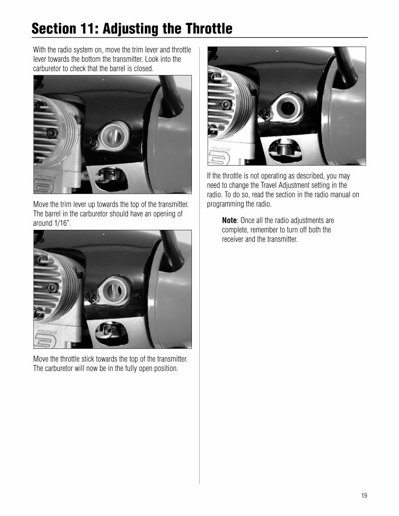
With the radio system on, move the trim lever and throttle lever towards the bottom the transmitter. Look into the carburetor to check that the barrel is closed.
Move the trim lever up towards the top of the transmitter. The barrel in the carburetor should have an opening of around 1/16".
Move the throttle stick towards the top of the transmitter. The carburetor will now be in the fully open position.
If the throttle is not operating as described, you may need to change the Travel Adjustment setting in the radio. To do so, read the section in the radio manual on programming the radio.
Note: Once all the radio adjustments are complete, remember to turn off both the receiver and the transmitter.
Section 11: Adjusting the Throttle
20
In order for your P-51 Mustang PTS to fly correctly, you will need to check the balance of the plane. This is done by supporting the aircraft either using your fingers, or by using a balancing stand. Not checking the balance can result in an aircraft that is difficult to fly, which can lead to the possibility of crashing your model.
Marking the Balance PointThe first step in balancing your P-51 Mustang PTS is to mark the location for the balance point. Measure back 4
1/2" against the fuselage to the very front edge of the wing, which is where the wing plugs into the fuselage. Mark the location on both sides of the fuselage using a felt-tipped pen to mark the balance location.
Lifting the Model and ObservationsThe P-51 Mustang PTS is balanced using either your fingers or a balancing stand. The stand in the photo was made from a dowel rod and a flat piece of wood. The dowel was cut down and holes drilled in the wood, then the dowel plugged into the wood. Use pencil erasers to prevent the ends of the dowel from damaging your wing. Place or lift the airplane so it is supported at the marks made in the previous step. The plane will rest level when balanced correctly. If not, weights must be added to correct any balancing problems.
Balanced Correctly
Nose Heavy – Add Weight to Tail
Tail Heavy – Add Weight to Nose
Section 12: Balancing Your P-51 PTS
21
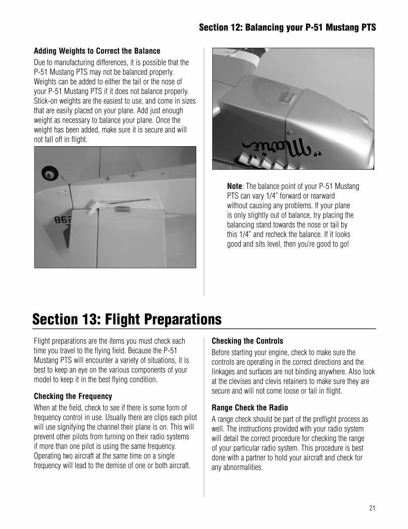
Adding Weights to Correct the BalanceDue to manufacturing differences, it is possible that the P-51 Mustang PTS may not be balanced properly. Weights can be added to either the tail or the nose of your P-51 Mustang PTS if it does not balance properly. Stick-on weights are the easiest to use, and come in sizes that are easily placed on your plane. Add just enough weight as necessary to balance your plane. Once the weight has been added, make sure it is secure and will not fall off in flight.
Flight preparations are the items you must check each time you travel to the flying field. Because the P-51 Mustang PTS will encounter a variety of situations, it is best to keep an eye on the various components of your model to keep it in the best flying condition.
Checking the FrequencyWhen at the field, check to see if there is some form of frequency control in use. Usually there are clips each pilot will use signifying the channel their plane is on. This will prevent other pilots from turning on their radio systems if more than one pilot is using the same frequency. Operating two aircraft at the same time on a single frequency will lead to the demise of one or both aircraft.
Checking the ControlsBefore starting your engine, check to make sure the controls are operating in the correct directions and the linkages and surfaces are not binding anywhere. Also look at the clevises and clevis retainers to make sure they are secure and will not come loose or fail in flight.
Range Check the RadioA range check should be part of the preflight process as well. The instructions provided with your radio system will detail the correct procedure for checking the range of your particular radio system. This procedure is best done with a partner to hold your aircraft and check for any abnormalities.
Note: The balance point of your P-51 Mustang PTS can vary 1/4” forward or rearward without causing any problems. If your plane is only slightly out of balance, try placing the balancing stand towards the nose or tail by this 1/4” and recheck the balance. If it looks good and sits level, then you’re good to go!
Section 12: Balancing your P-51 Mustang PTS
Section 13: Flight Preparations
22
Fueling the P-51 Mustang PTSFill the fuel tank with the proper fuel. Fill the tank by connecting the fuel pump to the line going to the needle valve. Disconnect the fuel line attached to the pressure fitting of the muffler; your tank is full when fuel begins to run out of the pressure line. Reconnect the fuel lines to the needle valve assembly and muffler.
Note: It is very important to reconnect the lines to the correct place. If they are reconnected incorrectly, the engine will not run properly.
Starting the Evolution EngineTo prime your engine, first turn on your transmitter and then your receiver. Move the throttle to full open and place your finger over the carburetor opening. Turn the propeller over by hand until you can see fuel entering the fuel line. Move the throttle stick full down to idle.
Caution: Always have a helper hold your airplane when starting the engine.
Move the throttle to the low position and the throttle trim lever to the middle position. Place the glow driver on the glow plug and, using a start stick, turn the propeller counterclockwise through the compression stroke. You should feel a “bump” against the start stick. When you feel the “bump”, flip the propeller counterclockwise to start the engine. Repeat the process if the engine does not start.
Adjusting the NeedlesModel engines run on a mixture of fuel and air. The high-speed and low-speed needle valves control the ratio of fuel to air that the engine receives. If you find that small adjustments are needed, have an experienced modeler help you to fine-tune your engine. Do not attempt to move the needles past the preset stops.
High-Speed Needle Adjustment
Low-Speed Needle Adjustment
Warning: Make all adjustments to the Evolution engine’s low-speed needle valve with the engine stopped.
Our technicians have preset the needle valves of the Evolution engine. Your engine should run properly at these preset needle settings. On occasion, depending on your location, you may find it necessary to adjust the high-speed and low-speed needle valves to optimize the performance of your engine. The needle valves have limiters to allow small adjustments to the engine. The low-speed needle valve limiter allows 1/4 turn of the needle valve, turning clockwise (in) will lean the mixture while turning counterclockwise (out) will richen the mixture to the low-speed or idle setting of the engine. The high-speed needle valve limiter allows one full turn of the needle valve. As with the low-speed adjustment, turning the high-speed needle valve clockwise (in) will lean the mixture, while turning counterclockwise (out) will richen the mixture of the high-speed setting of the engine.
Section 13: Flight Preparations
23
Clean UpAfter a long flying session with your P-51 Mustang PTS you will want to clean it up before loading it into your vehicle to head home. Use a cleaner such as Windex® or 409® and a paper towel to wipe down the exterior of your plane, removing the fuel residue. Remember a clean plane will last longer since the fuel won’t be allowed to soak into any exposed wood.
Checking the PropellerIf you have had any not so great landings, you will want to inspect the propeller for any damage. Small nicks and scratches can quickly become fractures, causing the propeller to be unsafe for flight. Always carry a few spare propellers so a damaged propeller can be replaced at the field, increasing your flying time per trip to the field.
Fine-Tuning the High-Speed NeedleStart your engine and advance the throttle to full, and then pinch the fuel line going to the engine. If the engine dies immediately without an increase in rpm, the setting is too lean. Adjust the high-speed needle valve counterclockwise (out) 1/2 turn and repeat the test. When the high-speed needle is adjusted correctly, the engine should increase rpm slightly and then quit. If the engine rpm increases more than 200–300 rpm and continues to run, the needle valve setting is too rich. Adjust the needle valve clockwise (in) 1/8th of a turn and repeat the test until the engine responds correctly to the pinch test.
Fine-Tuning the Low-Speed NeedleAfter fine-tuning the high-speed needle, you can begin to test the low-speed needle. Start your engine and go to full throttle for approximately 5–10 seconds then return to idle. Pinch the fuel line going to the engine. If the engine dies immediately without an increase in rpm, the setting is too lean. Adjust the needle valve counterclockwise (out) 1/8th of a turn and repeat the test. When the low-speed needle is adjusted correctly, the engine should increase rpm slightly and then quit. If the engine rpm increases more than 200–300 rpm and continues to run, the needle-valve setting is too rich. Adjust the needle valve clockwise (in) 1/16th of a turn and repeat the test until the engine responds correctly to the pinch test.To keep your P-51 Mustang PTS in the best condition, there are a few items that should be done after you have completed your day at the flying field.
Section 14: Maintaining Your P-51 Mustang PTS
Section 13: Flight Preparations
24
The P-51 Mustang PTS is a special trainer plane in that it will allow you to go from learning the basics of flight all the way up to performing aerobatics without upgrading or purchasing a new plane. As you learn to fly and become ready for a little more challenge, the P-51 Mustang PTS will grow with you.
IntermediateOnce you instructor feels you have mastered the basics and are ready for a little faster model, step one in the progressive training system is to remove the Speed Brakes. This will allow the P-51 Mustang PTS to achieve a higher top speed and challenge you a little more.
Step 1Use side cutters to trim the tie wraps from the speed brakes to remove them from your plane. Save the speed brakes for future use.
AdvancedAfter you have mastered flying the P-51 Mustang PTS at a faster pace, the next step is to neutralize the flaps.
Step 1Disconnect the flap linkage from the flap control horns. Remove the linkage from the linkage stay.
Step 2Move the linkage to the forward hole in the flap linkage stay.
Section 15: Progressing with Your Flying Skills
25
Step 3Reconnect the clevises and check that the flaps are in neutral, which is level with the wing center section. Check both the right and left flaps.
GraduateOnce you are comfortable soloing your P-51 Mustang PTS in this configuration, you’re ready to graduate to advanced flight and aerobatics. The last step is to remove the clear anti-spin NACA Droops. This is done by simply removing the clear tape on the top and bottom that holds them in place on the wing. With the Droops removed, your P-51 Mustang PTS is now an all out aerobatic warbird. Have your instructor near buy for the first few flights. The P-51 Mustang PTS will now descend more quickly and land faster like a sport model. In the air, you can now do a variety of aerobatics such as rolls, loops, spins and snap rolls.
Step 1The droops are held on with clear tape. Simply pulling the tape will allow you to remove the droops. Save the wing droops in case you may want to use them for training a budding young pilot in the future.
Section 15: Progressing with Your Flying Skills
26
After you have graduated from the Progressing Training System and are enjoying your P-51 Mustang PTS in its aerobatic mode, you can take it even a step further and add functional flaps. To do this, you’ll need to purchase an additional servo from your local hobby shop such as the JR 537 servo. Then, simple remove the covering over the flap servo slot in the center of the wing and install the servo. Hook up the linkage to the servo following the directions and you have a scale P-51 Mustang complete with functioning landing flaps.
Required Tools• Plier (2) • Drill bit: 1/16"
Step 1Remove the flap linkage from the aircraft.
Step 2Remove the flap linkage stay from the wing. Be careful when removing the stay as not to damage the wing.
Step 3The “Z” bend in the linkage will need to be rotated 90-degrees to connect to the servo. Use two pairs of pliers, one to hold the linkage, and the other to twist the “Z” bend.
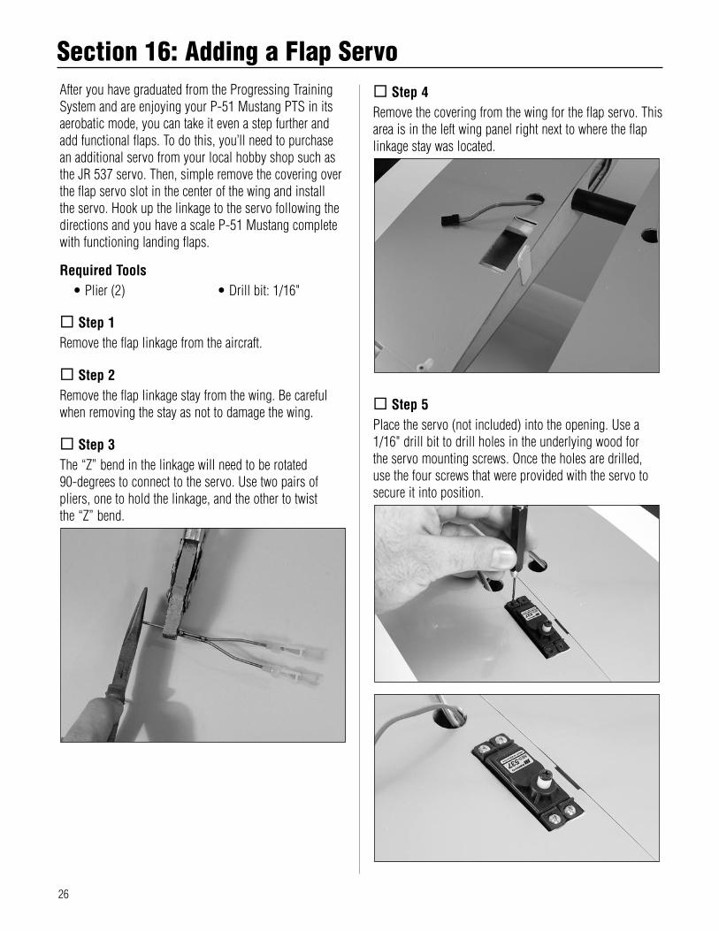
Step 4Remove the covering from the wing for the flap servo. This area is in the left wing panel right next to where the flap linkage stay was located.
Step 5Place the servo (not included) into the opening. Use a 1/16" drill bit to drill holes in the underlying wood for the servo mounting screws. Once the holes are drilled, use the four screws that were provided with the servo to secure it into position.
Section 16: Adding a Flap Servo
27
Note: Make sure to read the instructions included with the servo for installing the grommets and brass eyelets.
Step 6Plug the servo into the 5th channel of the receiver.
Step 7Turn on your radio system. Move the control on the transmitter to the up position. Attach the servo arm and secure it with the screw provided with the servo. The servo arm should be offset towards the leading edge of the wing as shown in the photo. Attach the flap linkage to the flap servo arm.
Step 8Check the operation of the flaps from the radio system. The flaps will now move from up to a lowered position using the radio system.
Section 16: Adding a flap servo
28
• Ailerons: Each side of this airplane has a hinged control surface (aileron), located on the trailing edge of the wing. Move the aileron stick on the transmitter left, the left aileron moves up and the right aileron moves down. Moving the left aileron up causes more drag and less lift, causing the left wing to drop down. When the right aileron moves down, more lift is created, causing the right wing to rise. This interaction causes the airplane to turn or roll to the left. Perform the opposite actions, and the airplane will roll to the right..
• Clevis: The clevis connects the wire end of the pushrod to the control horn of the control surface. A small clip, the clevis has fine threads so that you can adjust the length of the pushrod.
• Control Horn: This arm connects the control surface to the clevis and pushrod.
• Dihedral: The degree of angle (V-shaped bend) at which the wings intersect the fuselage is called dihedral. More dihedral gives an airplane more aerodynamic stability. Some sailplanes and trainer planes with large dihedral dispense with ailerons and use only the rudder to control the roll and yaw.
• Elevator: The hinged control surface on the back of the stabilizer that moves to control the airplane’s pitch axis. Pulling the transmitter’s control stick toward the bottom of the transmitter moves the elevator upward, and the airplane begins to climb. Push the control stick forward, and the airplane begins to dive.
• Fuselage: The main body of an airplane.• Hinge: Flexible pieces used to connect the control
surface to the flying surface. All hinges must be glued properly and securely to prevent the airplane from crashing. (This has already been done for you on the Alpha Advanced trainer.)
• Horizontal Stabilizer: The horizontal flying surface of the tail gives the airplane stability while in flight.
• Leading Edge: The front of a flying surface.• Main Landing Gear: The wheel and gear assembly
the airplane uses to land. It is attached to the bottom of the fuselage.
• Nose Gear: The part of the landing gear that is attached to the nose of the fuselage. The nose gear is usually connected to the rudder servo to help you steer the airplane on the ground.
• Pitch Axis: The horizontal plane on which the airplane’s nose is raised or lowered. By moving the elevator, you can raise the airplane’s nose above the pitch axis (climb) or lower it below the pitch axis (dive).
• Pushrod: The rigid mechanism that transfers movement from the servo to the control surface.
• Roll Axis: The horizontal plane on which the airplane’s wings are raised or lowered. By adjusting the ailerons, you can drop a wing tip below the roll axis and cause the airplane to bank or roll.
• Rudder: The hinged control surface on the vertical stabilizer that controls the airplane’s yaw. Moving the rudder to the left causes the airplane to yaw left; moving the rudder to the right causes it to yaw right.
• Servo: The servo transforms your ground commands into physical adjustments of the airplane while it’s in the air.
• Servo Output Arm: A removable arm or wheel that connects the servo to the pushrod (also called servo horn).
• Spinner: Term describing the nose cone that covers the propeller hub.
• Threadlock: A liquid that solidifies; used to prevent screws from loosening due to vibration.
• Torque Rods: Inserted into the ailerons, these rigid wire rods run along the wing’s trailing edge, then bend downward and connects to the pushrod.
• Vertical Stabilizer: The vertical flying surface of the tail gives an airplane stability while in flight.
• Wheel Collar: The round retaining piece that anchors wheels in place on the wheel axle.
• Wing: The lifting surface of an airplane.• Yaw Axis: The vertical plane through which the
airplane’s nose rotates as it yaws to the left or to the right. The rudder controls the yaw axis.
Glossary of Terms
Flying Notes
30
GENERAL1) I will not fly my model aircraft in sanctioned events, air shows or model flying demonstrations until it has been proven to be airworthy by having been previously, successfully flight tested.2) I will not fly my model higher than approximately 400 feet within 3 miles of an airport without notifying the airport operator. I will give right-of-way and avoid flying in the proximity of full-scale aircraft. Where necessary, an observer shall be utilized to supervise flying to avoid having models fly in the proximity of full-scale aircraft.3) Where established, I will abide by the safety rules for the flying site I use, and I will not willfully and deliberately fly my models in a careless, reckless and/or dangerous manner.4) The maximum takeoff weight of a model is 55 pounds, except models flown under Experimental Aircraft rules.5) I will not fly my model unless it is identified with my name and address or AMA number, on or in the model. (This does not apply to models while being flown indoors.)6) I will not operate models with metal-bladed propellers or with gaseous boosts, in which gases other than air enter their internal combustion engine(s); nor will I operate models with extremely hazardous fuels such as those containing tetranitromethane or hydrazine.
7) I will not operate models with pyrotechnics (any device that explodes, burns, or propels a projectile of any kind) including, but not limited to, rockets, explosive bombs dropped from models, smoke bombs, all explosive gases (such as hydrogen-filled balloons), or ground mounted devices launching a projectile. The only exceptions permitted are rockets flown in accordance with the National Model Rocketry Safety Code or those permanently attached (as per JATO use); also those items authorized for Air Show Team use as defined by AST Advisory Committee (document available from AMA HQ). In any case, models using rocket motors as a primary means of propulsion are limited to a maximum weight of 3.3 pounds and a G series motor. (A model aircraft is defined as an aircraft with or without engine, not able to carry a human being.)8) I will not consume alcoholic beverages prior to, nor during, participation in any model operations.9) Children under 6 years old are only allowed on the flight line as a pilot or while receiving flight instruction.
RADIO CONTROL1) I will have completed a successful radio equipment ground range check before the first flight of a new or repaired model.2) I will not fly my model aircraft in the presence of spectators until I become a qualified flier, unless assisted by an experienced helper.3) At all flying sites a straight or curved line(s) must be established in front of which all flying takes place with the other side for spectators. Only personnel involved with flying the aircraft are allowed at or in the front of the flight line. Intentional flying behind the flight line is prohibited.4) I will operate my model using only radio control frequencies currently allowed by the Federal Communications Commission. (Only properly licensed Amateurs are authorized to operate equipment on Amateur Band frequencies.)
2005 Official AMA National Model Aircraft Safety Code
31
5) Flying sites separated by three miles or more are considered safe from site-to site interference, even when both sites use the same frequencies. Any circumstances under three miles separation require a frequency management arrangement, which may be either an allocation of specific frequencies for each site or testing to determine that freedom from interference exists. Allocation plans or interference test reports shall be signed by the parties involved and provided to AMA Headquarters. Documents of agreement and reports may exist between (1) two or more AMA Chartered Clubs, (2) AMA clubs and individual AMA members not associated with AMA Clubs, or (3) two or more individual AMA members.6) For Combat, distance between combat engagement line and spectator line will be 500 feet per cubic inch of engine displacement. (Example: .40 engine = 200 feet.); electric motors will be based on equivalent combustion engine size. Additional safety requirements will be per the RC Combat section of the current Competition Regulations.7) At air shows or model flying demonstrations, a single straight line must be established, one side of which is for flying, with the other side for spectators.8) With the exception of events flown under AMA Competition rules, after launch, except for pilots or helpers being used, no powered model may be flown closer than 25 feet to any person.9) Under no circumstances may a pilot or other person touch a powered model in flight.
Organized RC Racing Event10) An RC racing event, whether or not an AMA Rule Book event, is one in which model aircraft compete in flight over a prescribed course with the objective of finishing the course faster to determine the winner.A. In every organized racing event in which contestants, callers and officials are on the course:1. All officials, callers and contestants must properly wear helmets, which are OSHA, DOT, ANSI, SNELL or NOCSAE approved or comparable standard while on the racecourse.2. All officials will be off the course except for the starter and their assistant.3.”On the course” is defined to mean any area beyond the pilot/staging area where actual flying takes place.B. I will not fly my model aircraft in any organized racing event which does not comply with paragraph A above or which allows models over 20 pounds unless that competition event is AMA sanctioned.C. Distance from the pylon to the nearest spectator (line) will be in accordance with the current Competition Regulations under the RC Pylon Racing section for the specific event pending two or three pylon course layout.11) RC night flying is limited to low-performance models (less than 100 mph). The models must be equipped with a lighting system that clearly defines the aircraft’s attitude at all times.
2005 Official AMA National Model Aircraft Safety Code