p p -Cycles, Ring-Mesh Hybrids -Cycles, Ring-Mesh Hybrids and “Ring-Mining:” and “Ring-Mining:” Options for New and Evolving Optical Options for New and Evolving Optical Networks Networks Wayne D. Grover Wayne D. Grover [email protected][email protected]TR TR Labs Labs and University of Alberta and University of Alberta Edmonton, AB, Canada Edmonton, AB, Canada web site for related papers etc: web site for related papers etc: http://www.ee.ualberta.ca/~grov http://www.ee.ualberta.ca/~grov er/ er/ Please see also www.drcn.org ( “DRCN 2003” ) OFC 2003, OFC 2003, Tuesday March 25 2003, Atlanta, Tuesday March 25 2003, Atlanta, Georgia Georgia
Transcript
pp-Cycles, Ring-Mesh Hybrids -Cycles, Ring-Mesh Hybrids and “Ring-Mining:”and “Ring-Mining:”
Options for New and Evolving Optical NetworksOptions for New and Evolving Optical Networks
Wayne D. Grover Wayne D. Grover [email protected]@trlabs.ca TRTRLabsLabs and University of Alberta and University of Alberta
Edmonton, AB, CanadaEdmonton, AB, Canada
web site for related papers etc: web site for related papers etc:
A note to recipients following OFC 2003A note to recipients following OFC 2003
Dear colleague
It is my pleasure to provide you with the following softy-copy of the presentation slides I used at OFC 2003. If you wish to rely on this work, you may cite the related OFC paperas follows:
W. D. Grover, “p-Cycles, Ring-Mesh Hybrids and Ring-Mining:Options for New and Evolving Optical Networks,” Optical Fiber Communication Conference (OFC 2003), Atlanta, March 2003, Paper TuI1, Vol. 1, pp. 201- 203.
The paper (just cited) in the OFC Proceedings also gives further individual references on p-cycles,ring-mesh hybrids, and “ring-mining” that may be of use to you.
Thank you very much for your interest in this work. Any feedback, comments or questions aremost welcome.
Total protection capacity: 85 unitsRedundancy: 53.8%Optimal configuration dynamically computable or self-organized
p-Cycle Copies
Total: 7
Wayne D. Grover OFC 2003 10
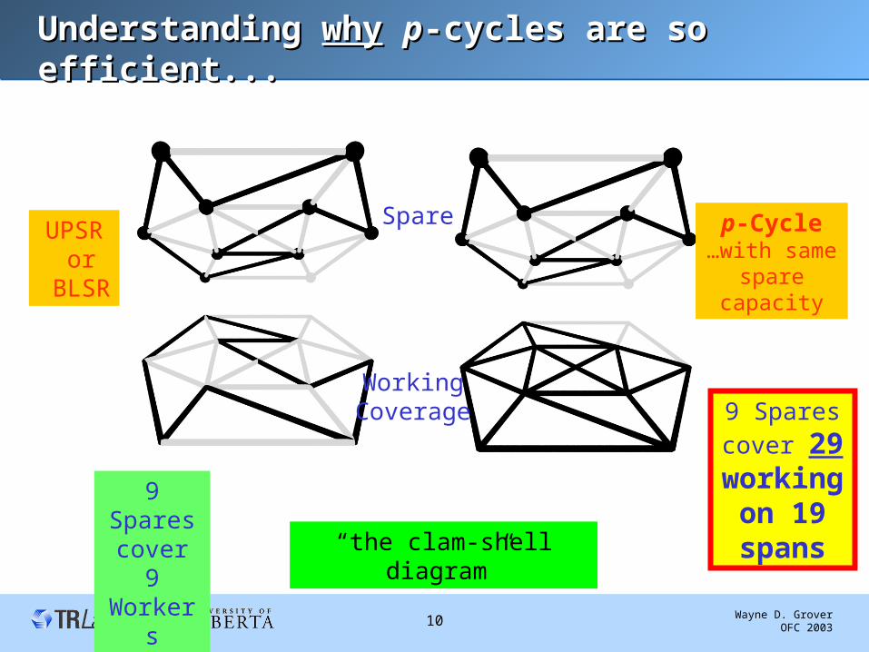
Understanding Understanding whywhy pp-cycles are so efficient...-cycles are so efficient...
9 Spares cover 9 Workers
9 Spares
cover 29 working
on 19 spans
Spare
Working Coverage
UPSR or
BLSR
p-Cycle…with same
spare capacity
“the clam-shell diagram”
Wayne D. Grover OFC 2003 11
ADM-like nodal device for ADM-like nodal device for pp-cycle networking-cycle networking
nodal redundancy =
spare 2 1
working 2 2 1
: 3 25%
R
k k
example k R
Wayne D. Grover OFC 2003 12
Summary: Important Features of Summary: Important Features of pp-Cycles-Cycles
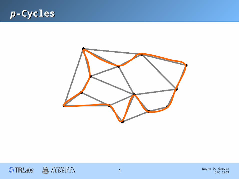
• Working paths go via shortest routes over the graph
• p-Cycles are formed only in the spare capacity
• Can be either OXC-based or based on ADM-like nodal devices
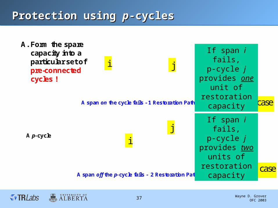
• a unit-capacity p-cycle protects:– one unit of working capacity for “on cycle” failures– two units of working capacity for “straddling” span failures
• Straddling spans:– there may be up to N(N-1)/2 -N straddling span relationships– straddling spans each bear two working channels and zero spare– -> mesh capacity efficiency
• Only two nodes do any real-time switching for restoration – protection capacity is fully pre-connected– switching actions are known prior to failure– -> BLSR speed
Wayne D. Grover OFC 2003 13
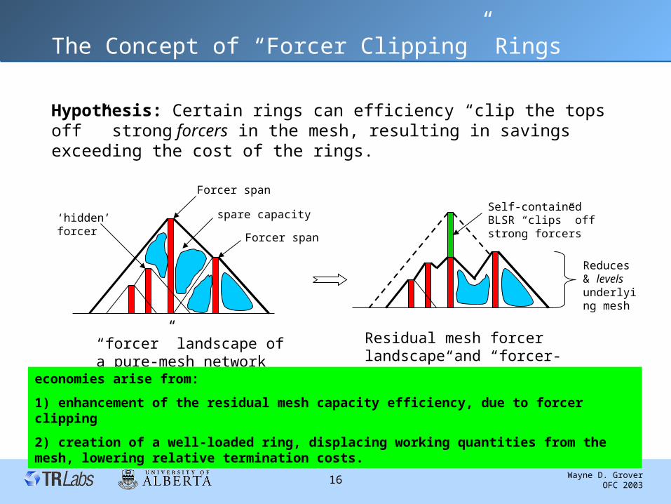
Ring-Mesh Hybrid Networks based on the “forcer-clipping”
principle
Wayne D. Grover OFC 2003 14
The architecture of integrated ring-mesh transportThe architecture of integrated ring-mesh transport
“Mining the Rings”:serving demand growth through ring to
mesh conversion
Wayne D. Grover OFC 2003 22
The “Ring-mining” PerspectiveThe “Ring-mining” Perspective
1) “Cap and grow:” Keep all current demands in the ring network and serve new demands in a new mesh network built on top of it
2) “Ring Mining:” Convert ring capacity to mesh capacity by conversion and/or re-use of transmission equipment
cap the
rings
grow new
mesh
convert operation to mesh
break open the
ringsi.e. What rings? - I only seecapacity on the ground.
Wayne D. Grover OFC 2003 23
Approaches to studying the ring-mining ideaApproaches to studying the ring-mining idea
• Q1 “pure ring mining”: If rings were simply “broken up” and reconfigured in a mesh architecture, how much total growth over existing demand could be served without having to add any new capacity?
Such that:
• all di,j demand quantities are multiplied by
• all (scaled up) demands are routed
• all (scaled up) demands are 100% span-restorable
• the total of routing and restoration flows over any
span uses only the capacity of the prior rings (W+P)
Maximize a total uniform growth multiplier
Wayne D. Grover OFC 2003 24
Sample ResultsSample Results
•35 % of the test cases could sustain a doubling of the demand or more.
• Three test networks could sustain ~ 3 x growth in demand...
0
0.05
0.1
0.15
0.2
0.25
0.3
0.35
0.4
1.1 1.3 1.5 1.7 1.9 2.1 2.3 2.5 2.6 2.9
, maximum sustainable growth multiplier
Rela
tive
Fre
quency
in +
/- 0
.1 b
ins.
17 ring-based test networks
• Ring mining tests on 17 efficient multi-ring network designs • Each design is at exhaust under its initial demand matrix
Wayne D. Grover OFC 2003 25
Why / How Ring Mining works …Why / How Ring Mining works …
• (1) Ring protection capacity is reclaimed – for general use as mesh working and spare capacity– 100% redundancy is reduced to mesh redundancy
• (2) Ring “stranded capacity” is freed.
• (3) New (growth) demands follow shortest-path routes over the facilities graph.
Wayne D. Grover OFC 2003 26
Ring Mining with Selective Capacity AdditionRing Mining with Selective Capacity Addition
• Pure mesh growth requires a high immediate investment in capacity
•Ring Mining with selective additions defers expenditure until 50% to 290 % growth.
Test case for 32 node, 45 span network initially with 7 rings covering 42 spans (3 “span eliminations”) optimized to serve the baseline demand before ring-to-mesh conversion.
0
20
40
60
80
100
120
1 1.5 2 2.5 , total uniform growth multiplier
Requir
ed C
apaci
ty I
nve
stm
ent New Mesh
Ring Mining
Range where other test case ring networks transition from pure ring mining to selected capacity additions
Wayne D. Grover OFC 2003 27
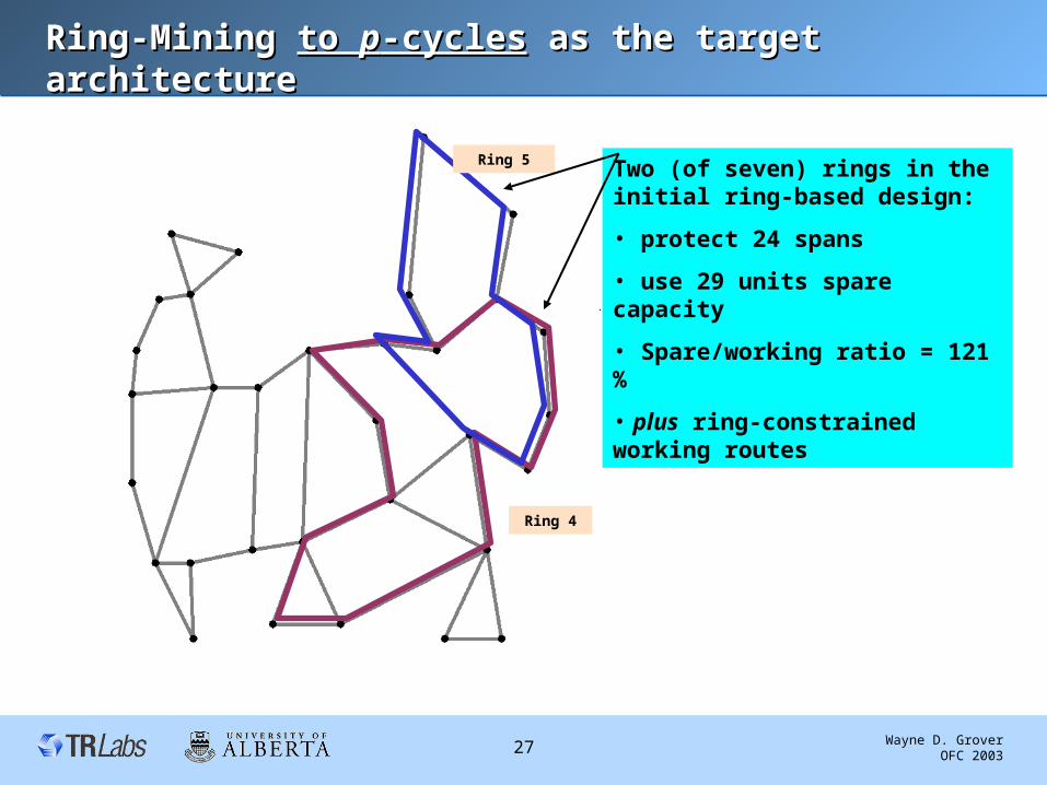
Ring-Mining Ring-Mining to to pp-cycles-cycles as the target architecture as the target architecture
Ring 4
Ring 5 Two (of seven) rings in the initial ring-based design:
• protect 24 spans
• use 29 units spare capacity
• Spare/working ratio = 121 %
• plus ring-constrained working routes
Wayne D. Grover OFC 2003 28
Convert those two rings to one Convert those two rings to one pp-cycle-cycle
p-cycle • No new capacity added
• 8 ADMs have p-cycle straddling span interface units added
• All other ADMs re-used as-is.
• 7units of protection capacity reclaimed as working
• 15 spans obtain on-cycle protection
• 5 spans obtain (x2) straddler protection
• fully loaded spare / working ratio 17/(17+5*2) = 63%
• pus working paths take shortest routes over topology
Wayne D. Grover OFC 2003 29
Straddling Span Interface Unit (SSIU)Straddling Span Interface Unit (SSIU)
• Converts an ADM to function as a p-cycle node
Long haul
Long haul Long haul
Long haul
Local Add Drop ChannelsW
S
W
W WW
S
W
Existing Ring ADM /OADM
Additional Local Add Drop Channels
p-cycle straddling span interface unit
“Extra Traffic” line-rate access to protection
Wayne D. Grover OFC 2003 30
SummarySummary
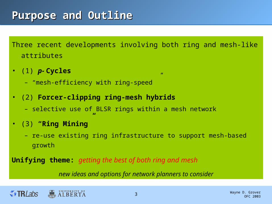
Three new options and architectural principles described
– p-Cycles • Mesh efficiency with ring-speed
– Ring-mesh hybrids based on forcer-clipping principle• Selective continued use of rings
• Possible target architecture of ring mining
– “Ring- mining”• A strategy for evolving legacy ring networks to a mesh future
… provide additional options and strategies for vendors and operators considering new and evolving optical networks. All involve aspects of harnessing both ring and mesh efficiencies
Wayne D. Grover OFC 2003 31
Selected References and Further ReadingSelected References and Further Reading• [1] W. Grover, D Stamatelakis, "Bridging the ring-mesh dichotomy with p-cycles", Proc. DRCN 2000,
Munich.
• [2] -------, "Cycle-oriented distributed preconfiguration: Ring-like speed with mesh-like capacity…," Proc. ICC'98, 1998, pp. 537-543.
• [3] ------, "OPNET Simulation of Self-organizing Restorable SONET Mesh Transport Networks", Proc. OPNETWORKS '98 (CD-ROM), Wash. D.C., April 1998, paper 04.
• [4] -----, "IP layer restoration … based on virtual protection cycles," IEEE JSAC, Oct. 2000, pp. 1938 - 1949.
• [5] D. A. Schupke, et.al., "Optimal configuration of p-cycles in WDM networks," Proc. ICC'02, NYC, 2002.
• [6] L.Lipes, "Understanding the trade-offs associated with sharing protection," OFC 2002, ThGG121.
• [7] W. D. Grover, J. E. Doucette, "Advances in optical network design with p-cycles: Joint optimization and pre-selection …," in Proc. IEEE-LEOS Topical Meetings, Quebec, July 15-17, 2002.
• [8] W.D. Grover, D.Y. Li, "The forcer concept and its applications to express route planning in mesh survivable networks," JNSM (Plenum Press), vol. 7, no.2, June 1999, pp. 199-223.
• [9] W. D. Grover, R. G. Martens, "Optimized Design of Ring-Mesh Hybrid Networks," DRCN 2000, Munich, April 2000.
• [10] M. Clouqueur, et. al. "Mining the Rings: Strategies for Ring-to-Mesh Evolution," DRCN 2001,
Budapest, October 2001.
Supplementary slidesSupplementary slides
Wayne D. Grover OFC 2003 33
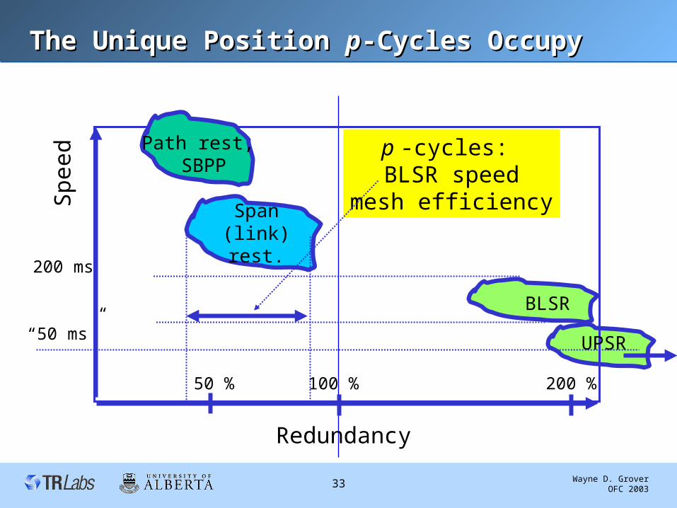
The Unique Position The Unique Position pp-Cycles Occupy-Cycles Occupy
Redundancy
Speed
“50 ms”
100 %50 % 200 %
Path rest, SBPP
Span (link)rest.
UPSR
200 ms
p -cycles: BLSR speed
mesh efficiency
BLSR
Wayne D. Grover OFC 2003 34
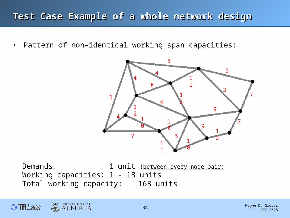
Test Case Example of a whole network designTest Case Example of a whole network design
• Pattern of non-identical working span capacities:
Demands: 1 unit (between every node pair)
Working capacities: 1 - 13 unitsTotal working capacity: 168 units
1
4
7
4
12
10
4
4
8
10
311
10
9
13
3
3
5
9
13
7
7
11
Wayne D. Grover OFC 2003 35
Test Case #4 SolutionTest Case #4 Solution
• Optimal solution:
A 3
B 1
C 1
D 4
E 1
F 1
G 2
Spans with overlapping cycles: 16Total protection capacity: 120 unitsDistance-weighted redundancy:65.9%
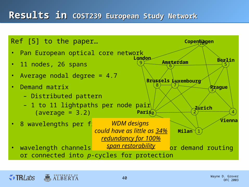
Results in Results in COST239 European Study NetworkCOST239 European Study Network
Ref [5] to the paper…
• Pan European optical core network
• 11 nodes, 26 spans
• Average nodal degree = 4.7
• Demand matrix
– Distributed pattern
– 1 to 11 lightpaths per node pair (average = 3.2)
• 8 wavelengths per fiber
• wavelength channels can either be used for demand routing or connected into p-cycles for protection
10
1
56
783
9
0 2 4
Copenhagen
LondonAmsterdam Berlin
Paris
Brussels LuxembourgPrague
Vienna
Zurich
Milan
WDM designs could have as little as 34%
redundancy for 100%span restorability
Wayne D. Grover OFC 2003 41
SummarySummary
• p-Cycles offer a promising new option for efficient realization of network protection– are preconfigured structures– use simple BLSR-like realtime switching– but are mesh-like in capacity efficiency
• Other recent advances can be superficially confused with p-cycles:– enhanced rings reduce ring network redundancy by sharing protection
capacity between adjacent rings– oriented cycle (double) covers adopt a undirectional graph cycle-
covering approach to avoid span overlaps
• Neither involves straddling spans; spans with working but no spare capacity– Both aim to approach their lower limits of 100% redundancy from well
above 100%– p-cycles are well below 100% redundancy
Wayne D. Grover OFC 2003 42
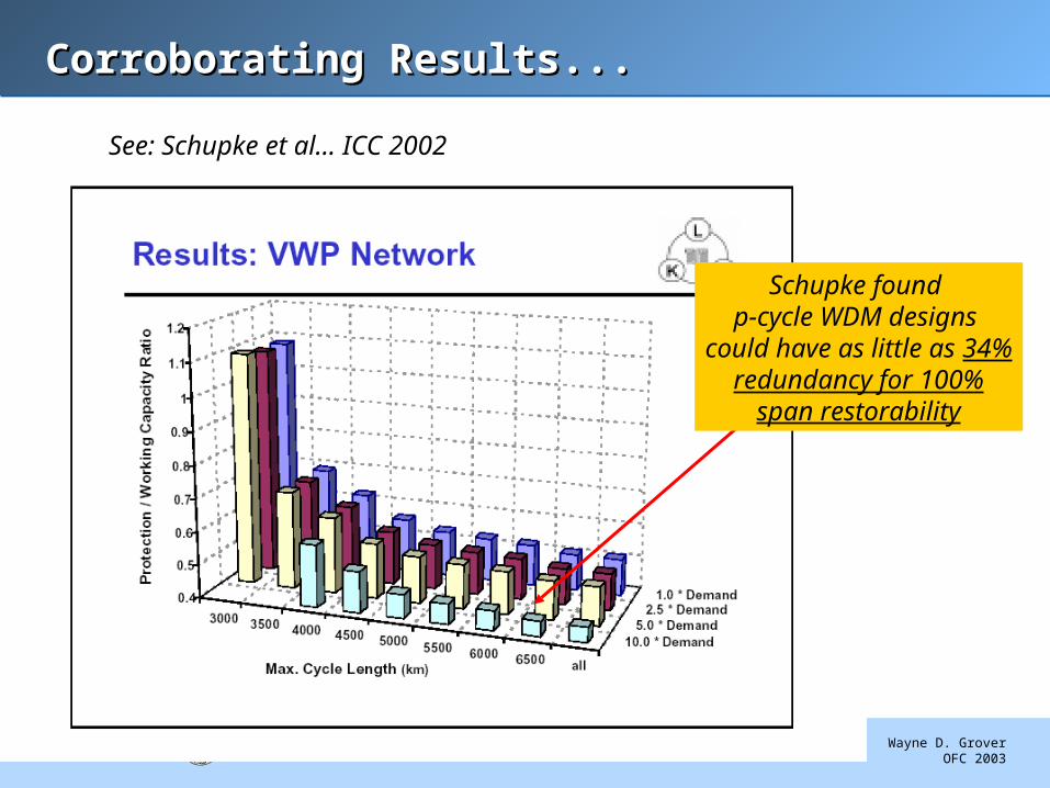
Corroborating Results...Corroborating Results...
See: Schupke et al… ICC 2002
Schupke found p-cycle WDM designs
could have as little as 34%redundancy for 100%
span restorability
Wayne D. Grover OFC 2003 43
Some Results ( ….. where optimal and heuristic can be compared)
Ring cost factor = 0.8
Objective function values, (% savings),execution time, number of rings
“Cost savings” arerelative to objectivefunction value for
“pure-mesh”
Network #1
11 nodes
23 spans
Network #2
11 nodes
20 spans
Network #3
15 nodes
28 spans
Average cost
savings %
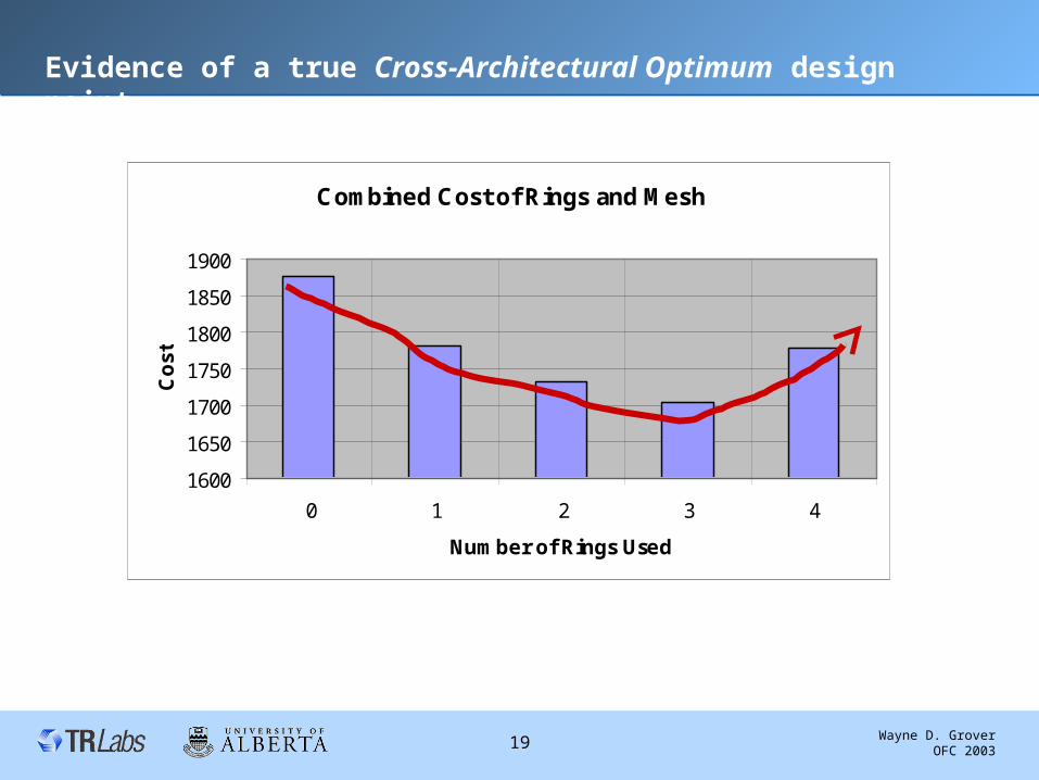
Initial Mesh
(reference case)1877 1705 2211
Heuristic #1
1750 (6.8 %)
7.3 min
1 ring
1504 (11.8%)
1.7 min
1 ring
2092 (5.4 %)
50.8 min
1 ring
8.0
Heuristic #2
1705 (9.2 %)
20.1 min
3 rings
1509 (11.5 %)
2.1 min
1 ring
2092 (5.4 %)
38.4 min
1 ring
8.7
Optimal Solution
Method
1667 (11.2 %)
36.9 min
4 rings
1487 (12.8 %)
6.3 min
3 rings
2088 (5.6 %)
25.3 hrs
4 rings
9.9
LP Lower Bound 1617 1437 1888
*
* result obtained with MIPGAP = 200
Wayne D. Grover OFC 2003 44
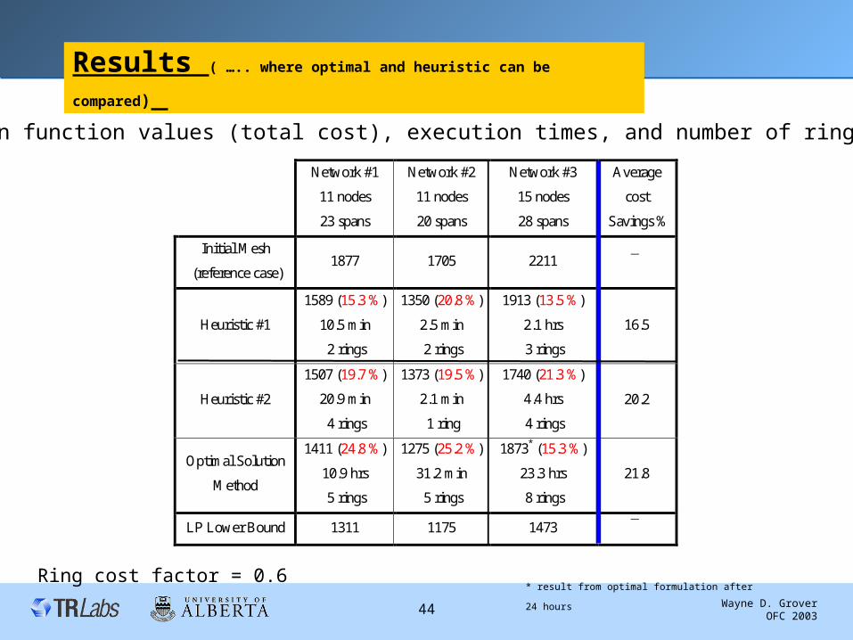
Results ( ….. where optimal and heuristic can be compared)
Ring cost factor = 0.6
Objection function values (total cost), execution times, and number of rings placed
Network #1
11 nodes
23 spans
Network #2
11 nodes
20 spans
Network #3
15 nodes
28 spans
Average
cost
Savings %
Initial Mesh
(reference case)1877 1705 2211
Heuristic #1
1589 (15.3 %)
10.5 min
2 rings
1350 (20.8 %)
2.5 min
2 rings
1913 (13.5 %)
2.1 hrs
3 rings
16.5
Heuristic #2
1507 (19.7 %)
20.9 min
4 rings
1373 (19.5 %)
2.1 min
1 ring
1740 (21.3 %)
4.4 hrs
4 rings
20.2
Optimal Solution
Method
1411 (24.8 %)
10.9 hrs
5 rings
1275 (25.2 %)
31.2 min
5 rings
1873* (15.3 %)
23.3 hrs
8 rings
21.8
LP Lower Bound 1311 1175 1473
* result from optimal formulation after 24
hours
Wayne D. Grover OFC 2003 45
Other Results (“ where only the heuristic can go”):
Heuristic
#2
% savings over optimal pure mesh
Number of rings placed
CPU time
Net #4
19 nodes
39 spans
Net #5
16 nodes
29 spans
Net #6
27 nodes
48 spans
23.8%
8 rings
11.9 hrs
38.6%
12 rings
1.0 hr
39.5%
11 rings
2.3 hrs
Wayne D. Grover OFC 2003 46
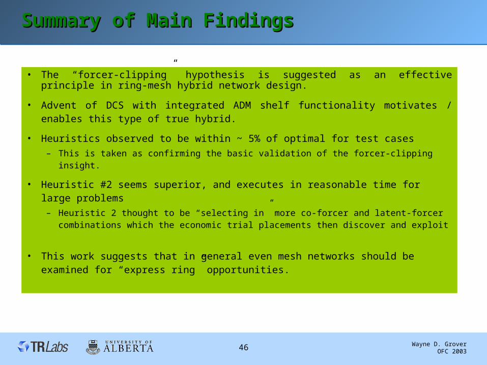
Summary of Main FindingsSummary of Main Findings
• The “forcer-clipping” hypothesis is suggested as an effective principle in ring-mesh hybrid network design.
• Advent of DCS with integrated ADM shelf functionality motivates / enables this type of true hybrid.
• Heuristics observed to be within ~ 5% of optimal for test cases
– This is taken as confirming the basic validation of the forcer-clipping insight.
• Heuristic #2 seems superior, and executes in reasonable time for large problems
– Heuristic 2 thought to be “selecting in” more co-forcer and latent-forcer combinations which the economic trial placements then discover and exploit
• This work suggests that in general even mesh networks should be examined for “express ring” opportunities.
Wayne D. Grover OFC 2003 47
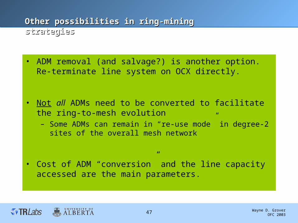
Other possibilities in ring-mining strategiesOther possibilities in ring-mining strategies
• ADM removal (and salvage?) is another option. Re-terminate line system on OCX directly.
• Not all ADMs need to be converted to facilitate the ring-to-mesh evolution– Some ADMs can remain in “re-use mode” in degree-2 sites of the
overall mesh network
• Cost of ADM “conversion” and the line capacity accessed are the main parameters.
Wayne D. Grover OFC 2003 48
Ring-mining” access to ring capacityRing-mining” access to ring capacity … …can be can be many alternativesmany alternatives
• “nail up” ADM in max add/drop configuration and access protection capacity via “extra traffic” ports.
OC-n ring ADMworking
protection
working
protection
“extra traffic”
(Or…) just salvage ADMs and re-terminate optical lines on OXCs
maximal workingadd / drop
up to 2 x OC-n total capacity to mesh cross-connect
Wayne D. Grover OFC 2003 49
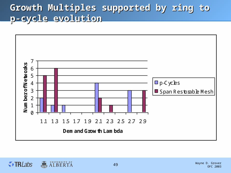
Growth Multiples supported by ring to p-cycle Growth Multiples supported by ring to p-cycle evolutionevolution
Demand Growth Sustained without capacity Addition
0
12
3
4
56
7
1.1 1.3 1.5 1.7 1.9 2.1 2.3 2.5 2.7 2.9
Demand Growth Lambda
Nu
mb
er
of
Ne
two
rks
p-Cycles
Span Restorable Mesh
p-Cycle straddling span interface
Long haul
Long haul Long haul
Long haul
Local Add Drop ChannelsW
S
W
W WW
S
W
Ring ADM /OADM
Additional Local Add Drop Channels
p-cycle straddling span interface unit
Cross-office Electrical/optical ring line rate
interface
“Extra Traffic” line-rate access to protection fiber(IF – 1 )
“Extra Traffic” line-rate access to protection fiber(IF
– 2 )
All Working fiber pairs ( ring line-rate ) that can be used to interface with straddler spans.
Patent Pending
Assuming that the protection fiber ( S) is
independently accessible through the “extra traffic” feature
interface
Source : “Ring-like speed with mesh-like capacity” presentation to Nortel by Dr Wayne Grover on 29th Aug 2002 : http://www.ee.ualberta.ca/~grover
Device used to interface straddling spans.
Wayne D. Grover OFC 2003 51
Staddling Span Interface Unit (SSIU)Staddling Span Interface Unit (SSIU)
• Converts an existing ADM to function as a p-cycle node