29
PHD COURSE ON NUCLEAR MICROELECTRONICS Luca Miari 785753 Alessandro Ruggeri 802434 TOWARDS MILLIMETER RESOLUTION IN TIME-OF-FLIGHT PET
| Date post: | 18-Dec-2015 |
| Category: |
Documents |
| Upload: | dustin-young |
| View: | 213 times |
| Download: | 0 times |
PHD COURSE ONNUCLEAR
MICROELECTRONICSLuca Miari785753
Alessandro Ruggeri802434
TOWARDS MILLIMETER RESOLUTION IN
TIME-OF-FLIGHT PET
A. Ruggeri, L. Miari2013, July 10th2
OUTLINE
1. Positron Emission Tomography
2. Image Reconstruction
3. SNR Enhancement in TOF PET
4. Scintillators & Detectors Evolution
5. Discrete vs Integrated Acquisition Chain
6. State-of-the-art timing TAC

A. Ruggeri, L. Miari2013, July 10th3
POSITRON EMISSION TOMOGRAPHY
Patients are injected with radioactive drug
Radionuclide decays emitting a positron
Positron annihilates with an electron of the tissue
Back-to-back gamma ray@ 511 keV is emitted
Two detectors register a hit
Positron lies on line defined by detector pair.

A. Ruggeri, L. Miari2013, July 10th4
IMAGE RECONSTRUCTION
It contains information about the positron emission rate along the line of response
The projection of a 2D image on a 1D line is called Radon Transform
By rotating the projection line of an angle θ I get the sinogram of the 2D image
Sinogram is 2π periodic

A. Ruggeri, L. Miari2013, July 10th5
IMAGE RECONSTRUCTION
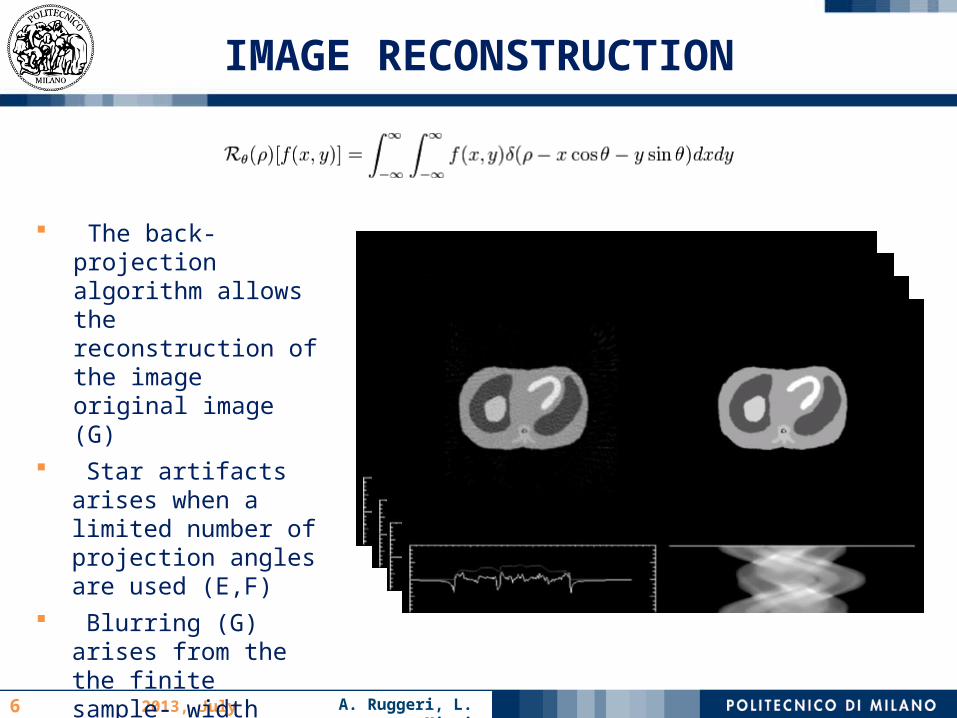
The back-projection algorithm allows the reconstruction of the image original image (G)
Star artifacts arises when a limited number of projection angles are used (E,F)
Blurring (G) arises from the the finite sample- width
By HP-filtering the sinogram the resulting image becomes sharper
A. Ruggeri, L. Miari2013, July 10th6
IMAGE RECONSTRUCTION
The back-projection algorithm allows the reconstruction of the image original image (G)
Star artifacts arises when a limited number of projection angles are used (E,F)
Blurring (G) arises from the the finite sample- width
By HP-filtering the sinogram the resulting image becomes sharper

A. Ruggeri, L. Miari2013, July 10th7
IMAGE RECONSTRUCTION
Arc correction resampling is necessary before back-projecting because of the circular distribution of the detectors
False coincidence events decrease SNR
A. Ruggeri, L. Miari2013, July 10th
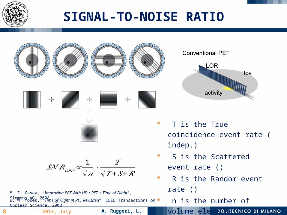
SIGNAL-TO-NOISE RATIO
8
W. W. Moses, “Time of Flight in PET Revisited”, IEEE Transactions on Nuclear Science, 2003
𝑆𝑁 𝑅𝑐𝑜𝑛𝑣∝1
√𝑛⋅
𝑇√𝑇 +𝑆+𝑅
T is the True coincidence event rate ( indep.)
S is the Scattered event rate ()
R is the Random event rate ()
n is the number of volume elements influencing the noise (
M. E. Casey, “Improving PET With HD • PET + Time of Flight”, Siemens AG, 2008

A. Ruggeri, L. Miari2013, July 10th
SIGNAL-TO-NOISE RATIO
9
When n become smaller:
TOF SNR Gain:
Δ𝑥=Δ𝑡 ⋅𝑐2
M. Conti, “State of the art and challenges of time-of-flight PET”, Physica Medica, 2009
M. E. Casey, “Improving PET With HD • PET + Time of Flight”, Siemens AG, 2008

A. Ruggeri, L. Miari2013, July 10th
TOF: BENEFITS & REQUIREMENTS
10
BENEFITS Temporal resolution of 50 ps allows sub-
centimeter spatial resolution Current resolution of 500 ps () do not
improve spatial resolution but reduces statistical noise:
Usually : reduces computational time and numbers of iteration
REQUIREMENTS FOR MILLIMETER RESOLUTION Fast scintillators (with ns decay
constant) Low Jitter detectors Timing ElectronicsM. Conti, “Focus on time-of-flight PET: the benefits of improved time resolution”, Eur J Nucl
Med Mol Imaging, 2011W. W. Moses, “Time of Flight in PET Revisited”, IEEE Transactions on Nuclear Science, 2003

A. Ruggeri, L. Miari2013, July 10th11
SCINTILLATORS: 1980
M. Ter-Pogossian, D. Ficke, M. Yamamoto, J. Hood, “Super PETT 1: A Positron Emission Tomography Utilizing Photon Time-of-Flight Information“, IEEE Transactions on Medical Imaging, 1982
First TOF faced scintillators limitations: High Z scintillator had high
output yield, high energy resolution, could be made smaller but had slow decay constant
Scintillator with fast decay constant (like CsF) had opposite performance and so TOF studies were abandoned

A. Ruggeri, L. Miari2013, July 10th12
SCINTILLATORS: 2000
S. Surti, J.S. Karp, G. Muehllehner, “Investigation of Lanthanum Scintillators for 3-D PET“, IEEE Transactions on Nuclear Science, 2003
1980: CsF and BaF2
Very Fast Decay ConstantVery Low Light YieldLow Energy Resolution
2000: LaCl3 and LaBr3
Fast Decay Constant Very High Light Yield High Energy Resolution
New scintillators renewed scientific interest in TOF PET
Measurements @ 664 keV shows Energy Resolution of 4.6 %
FWHM Timing Resolution of 350 ps
FWHM
A. Ruggeri, L. Miari2013, July 10th13
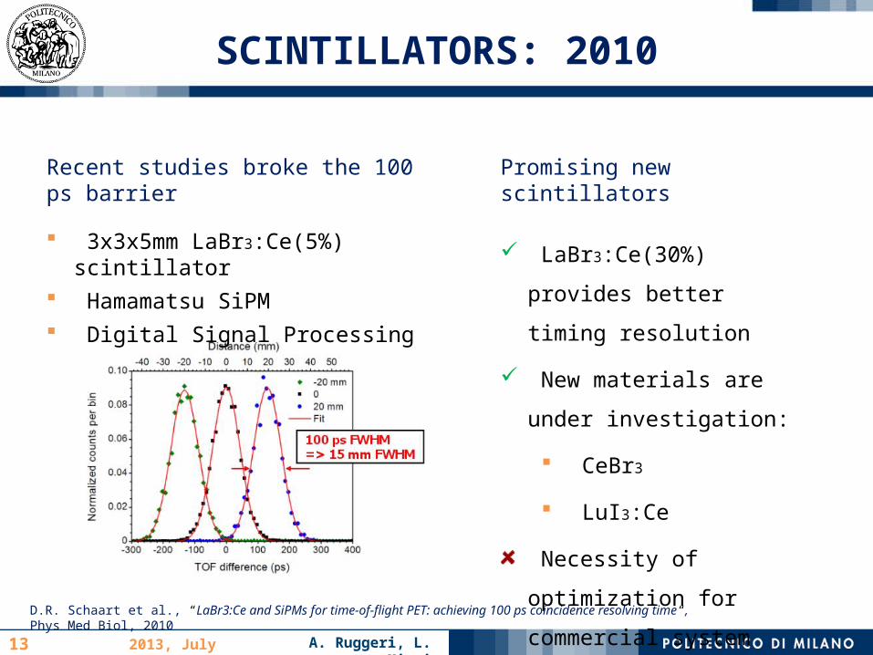
SCINTILLATORS: 2010
Recent studies broke the 100 ps barrier
3x3x5mm LaBr3:Ce(5%) scintillator
Hamamatsu SiPM Digital Signal Processing
D.R. Schaart et al., “LaBr3:Ce and SiPMs for time-of-flight PET: achieving 100 ps coincidence resolving time“, Phys Med Biol, 2010
Promising new scintillators
LaBr3:Ce(30%) provides
better timing resolution
New materials are under
investigation:
CeBr3
LuI3:Ce
Necessity of optimization
for commercial system
A. Ruggeri, L. Miari2013, July 10th14
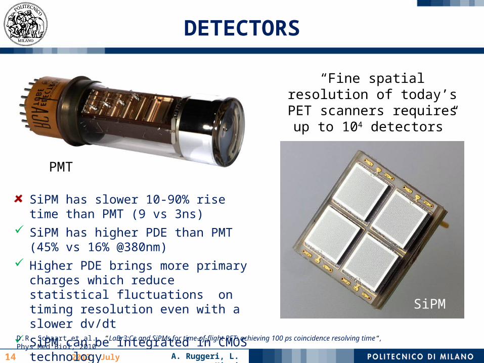
DETECTORS
PMT
SiPM
SiPM has slower 10-90% rise time than PMT (9 vs 3ns)
SiPM has higher PDE than PMT (45% vs 16% @380nm)
Higher PDE brings more primary charges which reduce statistical fluctuations on timing resolution even with a slower dv/dt
SiPM can be integrated in CMOS technology
“Fine spatial resolution of today’s PET scanners requires up
to 104 detectors”
D.R. Schaart et al., “LaBr3:Ce and SiPMs for time-of-flight PET: achieving 100 ps coincidence resolving time“, Phys Med Biol, 2010
A. Ruggeri, L. Miari2013, July 10th15
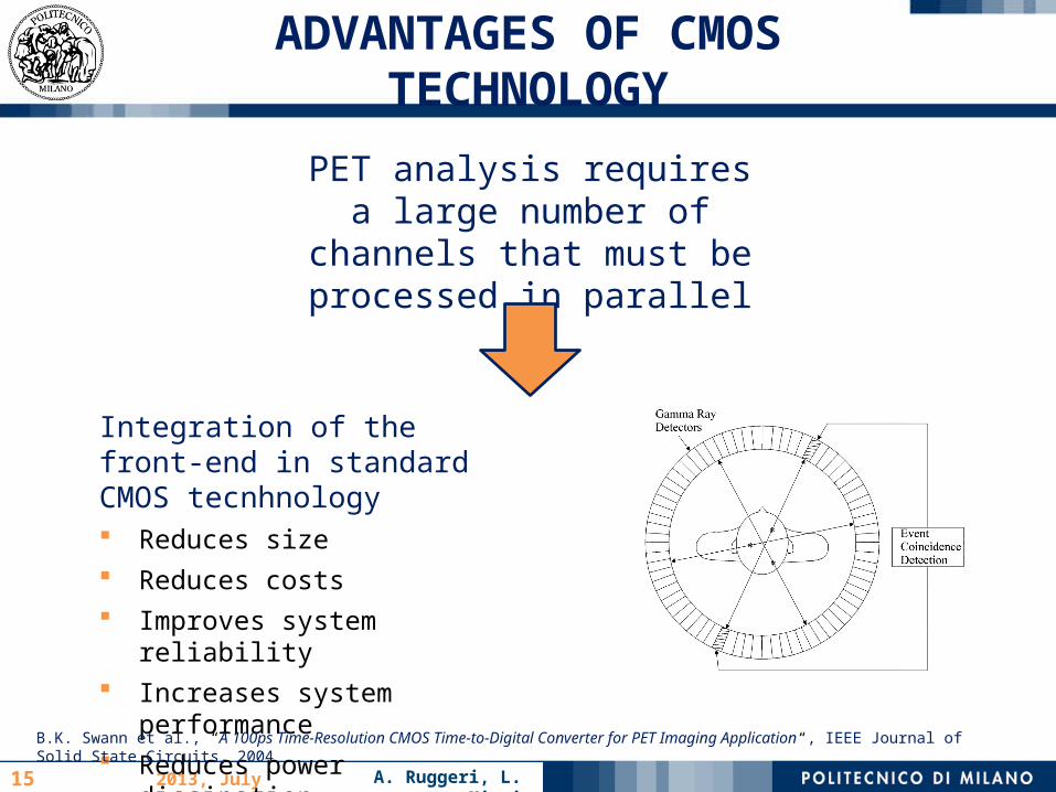
ADVANTAGES OF CMOS TECHNOLOGY
PET analysis requires a large number of
channels that must be processed in parallel
Integration of the front-end in standard CMOS tecnhnology Reduces size Reduces costs Improves system reliability Increases system
performance Reduces power dissipationB.K. Swann et al., “A 100ps Time-Resolution CMOS Time-to-Digital Converter for PET Imaging Application“, IEEE Journal of
Solid State Circuits, 2004
A. Ruggeri, L. Miari2013, July 10th16
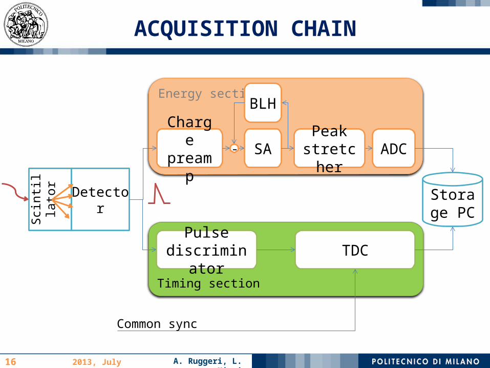
Timing section
Energy section
ACQUISITION CHAIN
Pulse discriminator
Scin
tilla
tor Detector
TDC
Charge preamp SA ADC
Storage PC
Common sync
Peak stretcher
BLH
-
A. Ruggeri, L. Miari2013, July 10th17
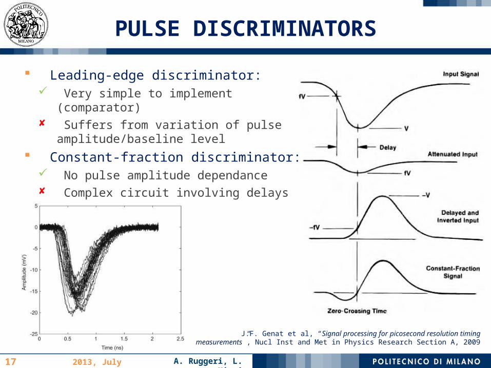
PULSE DISCRIMINATORS
J.F. Genat et al, “Signal processing for picosecond resolution timing measurements”, Nucl Inst and Met in Physics Research Section A, 2009
Leading-edge discriminator: Very simple to implement
(comparator) Suffers from variation of pulse
amplitude/baseline level Constant-fraction discriminator:
No pulse amplitude dependance Complex circuit involving delays
A. Ruggeri, L. Miari2013, July 10th18
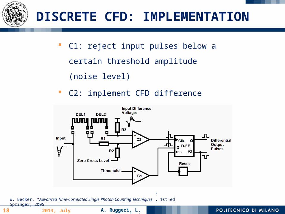
DISCRETE CFD: IMPLEMENTATION
C1: reject input pulses below a certain
threshold amplitude (noise level)
C2: implement CFD difference amplifier
Down to picosecond resolution
W. Becker, “Advanced Time-Correlated Single Photon Counting Techniques”, 1st ed. Springer, 2005
A. Ruggeri, L. Miari2013, July 10th19
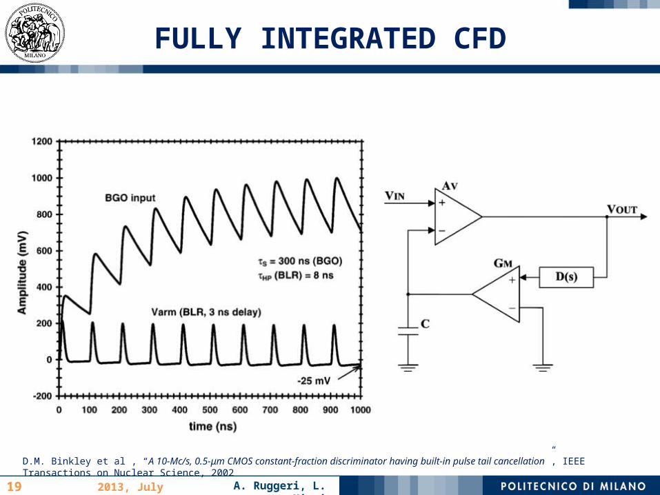
FULLY INTEGRATED CFD
D.M. Binkley et al , “A 10-Mc/s, 0.5-μm CMOS constant-fraction discriminator having built-in pulse tail cancellation”, IEEE Transactions on Nuclear Science, 2002
A. Ruggeri, L. Miari2013, July 10th20
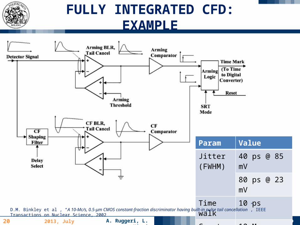
FULLY INTEGRATED CFD: EXAMPLE
Param Value
Jitter (FWHM)
40 ps @ 85 mV
80 ps @ 23 mV
Time walk 10 ps
Count rate 10 Mcps
D.M. Binkley et al , “A 10-Mc/s, 0.5-μm CMOS constant-fraction discriminator having built-in pulse tail cancellation”, IEEE Transactions on Nuclear Science, 2002

A. Ruggeri, L. Miari2013, July 10th21
FULLY INTEGRATED CFD: EXAMPLE
Baseline restorer removes pulse tail → reduced pileup
Current mode and differential circuits minimize harmonic distortion and noise coupling
D.M. Binkley et al , “A 10-Mc/s, 0.5-μm CMOS constant-fraction discriminator having built-in pulse tail cancellation”, IEEE Transactions on Nuclear Science, 2002

A. Ruggeri, L. Miari2013, July 10th22
FULLY INTEGRATED ACQUISITION CHAIN
H. Matsuda et al., “Development of ultra-fast ASIC for future PET scanners using TOF-capable MPPC detectors“, Nucl Inst&Met in Physics Research, 2013
CHAIN1 32 parallel channels 2 ICON based current
conveyor 2nd order shaping filter Energy discrimination for
position information Timing discrimination by
both leading edge and zero-crossing method
CHAIN2 Analog summing circuit for
energy information TAC for timing information Internal baseline restorer

A. Ruggeri, L. Miari2013, July 10th23
FULLY INTEGRATED ACQUISITION CHAIN
ASUM provides the energy spectrum (to be digitally converted)
LEDGE comparator acquires fast initial rising edges
Zero-crossing discriminator (FAST) provides a digital time-walk free signal (DSUM)
Performance 10.5%
(FWHM) @ 662 keV
9.8% (FWHM) @ 511 keV
491ps (FWHM) TOF info
H. Matsuda et al., “Development of ultra-fast ASIC for future PET scanners using TOF-capable MPPC detectors“, Nucl Inst&Met in Physics Research, 2013
A. Ruggeri, L. Miari2013, July 10th24
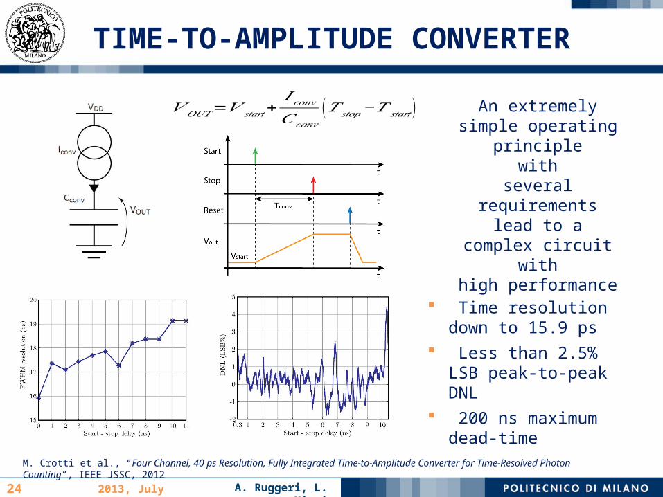
TIME-TO-AMPLITUDE CONVERTER
𝑉 𝑂𝑈𝑇=𝑉 𝑠𝑡𝑎𝑟𝑡+𝐼 𝑐𝑜𝑛𝑣𝐶𝑐𝑜𝑛𝑣
(𝑇 𝑠𝑡𝑜𝑝−𝑇 𝑠𝑡𝑎𝑟𝑡 )
M. Crotti et al., “Four Channel, 40 ps Resolution, Fully Integrated Time-to-Amplitude Converter for Time-Resolved Photon Counting“, IEEE JSSC, 2012
An extremelysimple operating
principlewith
several requirementslead to a
complex circuitwith
high performance
Time resolution down to 15.9 ps
Less than 2.5% LSB peak-to-peak DNL
200 ns maximumdead-time

A. Ruggeri, L. Miari2013, July 10th25
TIME-TO-AMPLITUDE CONVERTER
Idle Phase
TG1 ON (OA in buffer configuration)
Differential stage switches on M2
Conversion Phase (Start Event)
TG1 OFF Vout increases
Wait Phase (Stop Event)
Differential stage switches on M1
Conversion capacitor holds Vout
Reset Phase
TG1 ON discharges the capacitor
M2 ON resets to Idle Phase
M. Crotti et al., “Four Channel, 40 ps Resolution, Fully Integrated Time-to-Amplitude Converter for Time-Resolved Photon Counting“, IEEE JSSC, 2012
A. Ruggeri, L. Miari2013, July 10th26
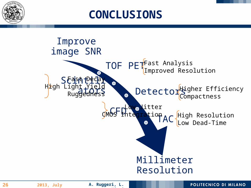
CONCLUSIONS
Improve image SNR
TOF PET
ScintillatorsDetectors
CFDTAC
Millimeter Resolution
Fast DecayHigh Light Yield
Ruggedness
Low JitterCMOS Integration
Fast AnalysisImproved Resolution
Higher EfficiencyCompactness
High ResolutionLow Dead-Time

A. Ruggeri, L. Miari2013, July 10th
A. Ruggeri, L. Miari2013, July 10th28
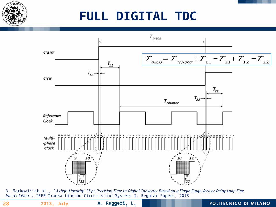
FULL DIGITAL TDC
B. Markovic et al., “A High-Linearity, 17 ps Precision Time-to-Digital Converter Based on a Single-Stage Vernier Delay Loop Fine Interpolation”, IEEE Transaction on Circuits and Systems I: Regular Papers, 2013
𝑇𝑚𝑒𝑎𝑠=𝑇 𝑐𝑜𝑢𝑛𝑡𝑒𝑟+𝑇11−𝑇 21+𝑇 12−𝑇22

A. Ruggeri, L. Miari2013, July 10th29
FULL DIGITAL TDC
B. Markovic et al., “A High-Linearity, 17 ps Precision Time-to-Digital Converter Based on a Single-Stage Vernier Delay Loop Fine Interpolation”, IEEE Transaction on Circuits and Systems I: Regular Papers, 2013
Performances 10 ps bin < 20 psrms
precision 160 ns range 0.9%RMS LSB DNL
4%MAX LSB DNL 0.3mm2 core area


