12
R Victor Taichung P P Victor Taichung – an established ISO 9001 & 14001 company P P
R
VictorTaichung
P P
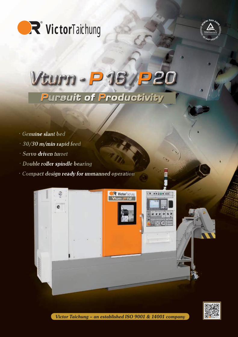
Victor Taichung – an established ISO 9001 & 14001 company
P P
1
WWiithh 66 ddeecaadeeess oof eexxppeerieenncce iin machinee maannuuffaactuurinnng, VViccttorr TTaaicchhunngg haas, nooott oonlly eenhhannnceed tthhee sttructure oof thee VVtturnn P--sserriess laattheess sslaantt beed anndd tturrrettt,, buut aaalsoo uupggrradded the rappid ffeeeed ratees iiinn oordeeerr tto iimmpproovee prrodduccttivvityy.
Victor Taichung’s Own Spindle Assembly ● Spindle and headstock are both in-house designed and
manufactured in the air conditioned assembly room to assure high quality and reliability.
● Every spindle has been inspected and tested with her own test record.
Run-up Testing
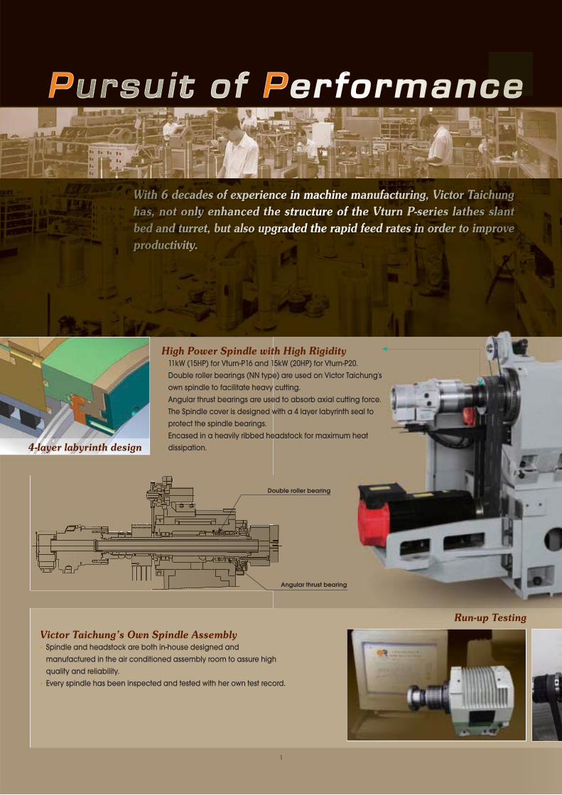
High Power Spindle with High Rigidity● 11kW (15HP) for Vturn-P16 and 15kW (20HP) for Vturn-P20.● Double roller bearings (NN type) are used on Victor Taichung's
own spindle to facilitate heavy cutting.● Angular thrust bearings are used to absorb axial cutting force.● The Spindle cover is designed with a 4 layer labyrinth seal to
protect the spindle bearings.● Encased in a heavily ribbed headstock for maximum heat
dissipation.
P P
4-layer labyrinth design
Angular thrust bearing
Double roller bearing
2
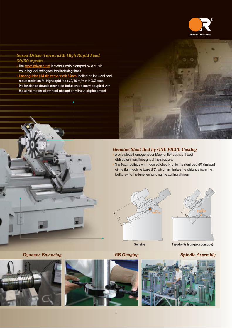
Genuine Slant Bed by ONE PIECE Casting ● A one piece homogeneous Meehanite® cast slant bed distributes stress throughout the structure.● The Z-axis ballscrew is mounted directly onto the slant bed (P1) instead
of the flat machine base (P2), which minimizes the distance from the ballscrew to the turret enhancing the cutting stiffness.
Dynamic Balancing GB Gauging Spindle Assembly
Servo Driver Turret with High Rapid Feed
30/30 m/min● The servo driven turret is hydraulically clamped by a curvic
coupling facilitating fast tool indexing times.● Linear guides (LM slideways width 35mm) bolted on the slant bad
reduces friction for high rapid feed 30/30 m/min in X/Z axes.● Pre-tensioned double anchored ballscrews directly coupled with
the servo motors allow heat absorption without displacement.
P2ballscrew P1
ballscrew L2
L1
Genuine Pseudo (By triangular carriage)

3
Minimum Chip Build-up● A Coolant flush onto the Z-axis cover reduces
chip accumulation.● The High volume L-Shaped coolant tank
reduces heat build-up enhancing machining accuracy.
● The coolant tank is removed from the front of the machine reducing the overall machine footprint.
P P
WWithh 22 deecaaddees oof eeexpperrieenncee in factorryy auutoommatioon,, Viictoorr TTaicchhuungg'ss Vtturrn PPP-sseriiesss lattheeess hhavve bbeeen compacctly deesiigneed aandd bbuuuiltt ennaabblinngg thhemm ttoo bbee innnteggraaateed wwiitth eeither arrticuulaateed oor ggganntryyy roobbottss ffoorr maaxxiimuuumm prrooddducctivviiitty..
Model Spindle Motor Base Speed (rpm)
Max. Speed (rpm)
P. _ Cont.kW (HP)
P.kW (HP)
Vturn-P16 α8i Single winding 1312 6000 7.5 (10) 11 (14.7) -30 min.
Opt.αP12i
Good for low speed turning
Low winding 500 1500 3.7 (5) 7.5 (10) -15 min.
High winding 750 6000 5.5 (7.4) 7.5 (10) -30 min.
Vturn-P20 α12i Single winding 1000 4200 11 (14.7) 15 (20) -30 min.
Opt.αP15i
Good for low speed turning
Low winding 350 1050 5 (6.7) 9 (12) -15 min.
High winding 525 4200 7.5 (10) 9 (12) -30 min.
*Photo: Single pallet work feeder
RPM
P1
Power(kW)
P2P3
P4
S1 S2 S3 S4
P1 (*30 min. in low winding)P2 (cont. in low winding)P3 (*30 min. in high winding)P4 (cont. in high winding)
S1 (base RPM in low winding)S2 (base RPM in high winding)S3 (max. RPM in low winding)S4 (max. RPM in high winding)
T1 (*30 min. in low winding)T2 (cont. in low winding)T3 (*30 min. in high winding)T4 (cont. in high winding)
S1 (base RPM in low winding)S2 (base RPM in high winding)S3 (max. RPM in low winding)S4 (max. RPM in high winding)
RPMS1 S2 S3 S4
T1T3T2
T4
Torque(kg-m)
Spindle Output
Coolant flush onto cover
4
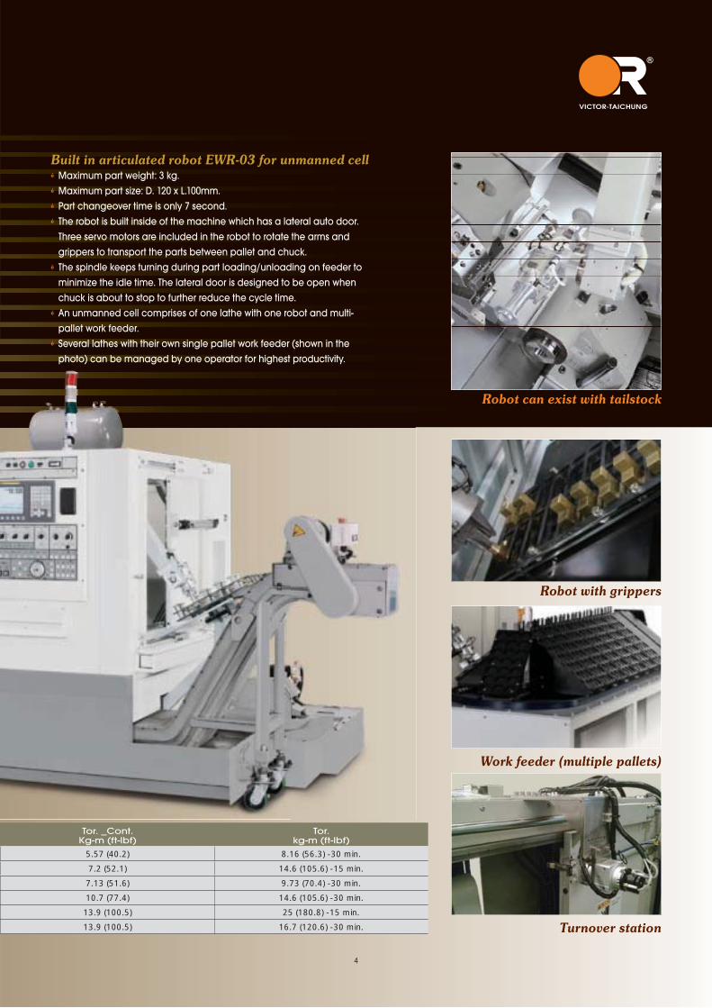
Built in articulated robot EWR-03 for unmanned cell● Maximum part weight: 3 kg.● Maximum part size: D. 120 x L.100mm.● Part changeover time is only 7 second.● The robot is built inside of the machine which has a lateral auto door.
Three servo motors are included in the robot to rotate the arms and grippers to transport the parts between pallet and chuck.
● The spindle keeps turning during part loading/unloading on feeder to minimize the idle time. The lateral door is designed to be open when chuck is about to stop to further reduce the cycle time.
● An unmanned cell comprises of one lathe with one robot and multi-pallet work feeder.
● Several lathes with their own single pallet work feeder (shown in the photo) can be managed by one operator for highest productivity.
Robot with grippers
Robot can exist with tailstock
Work feeder (multiple pallets)
Turnover station
Tor. _Cont.Kg-m (ft-lbf)
Tor.kg-m (ft-lbf)
5.57 (40.2) 8.16 (56.3) -30 min.
7.2 (52.1) 14.6 (105.6) -15 min.
7.13 (51.6) 9.73 (70.4) -30 min.
10.7 (77.4) 14.6 (105.6) -30 min.
13.9 (100.5) 25 (180.8) -15 min.
13.9 (100.5) 16.7 (120.6) -30 min.

Manual Tailstock with Power Quill
● The robust cast tailstock with hydraulic quill provides positive
engagement to minimize vibration.● Tailstock is towed by the turret and moved to the specified
location by rotating handwheel manually.
Reliable Power Chuck
● Hydraulic 3 jaw hollow chuck is foot operated for safe and easy
operation.
Standard Accessories
Ergonomic design for safe & easy operation
● Fully enclosed guarding with the chip conveyor fitted into the machine bed ensures no access to the machine during operation and no coolant leakages.
● Hydraulic gauges on the front so they can be easily monitored during operation.
● Coolant tank is accessed from the front of the machine and High pressure coolant by Grundfos® SPK2-3 improves the machining quality on part surface. The oil skimmer (option) can be installed on the coolant tank to separate wasted lube oil from coolants.
● Electrical cabinet is equipped with heat exchanger for efficient heat removal.
eation
ed
d
canrom
ent
ies
operatioon
5

Optional AccessoriesTool Presetter (Renishaw®)● No longer to perform tedious time consuming cuts to determine tool
geometry, the operator needs only to touch the tool tip to the tool presetter sensor to get the tool geometries not only reducing tool set-up time, but reducing down time due to tool breakage.
. Manual tool presetter (MTP): Arm is rotated manually.. Auto tool presetter (ATP): Arm is rotated automatically by
programming.
Parts catcher ● To enhance the machine's productivity, a parts catcher is available
to work in conjunction with bar feed.● This type of fully programmable parts catcher is mounted next to
the chuck with a hydraulic actuator to rotate the extending rod bolted with the catching bucket which rests against the door of the machine during machining.
Bar Feeder Interface ● For automatic loading of workpieces, the bar
feeder provides a simple yet highly effective system. Interfaces are available on the Vturn lathes so that a number of different barfeeding systems can be worked in conjunction with the lathe for an efficient turnkey.
Large Spindle Bore 66mm/4500rpm● Through the new layout on the upgraded spindle bearings, Large
Spindle Bore (LSB) for larger bar capacity 66mm is available on Vturn-P20 to reduce the expense and floor space demanded by an oversized machine. The spindle speed is even increased to 4500rpm because of bearing upgrade.
66mm
6

VICTOR Taichung’s FANUC 0i/32i Control SPECIFICATIONSStandard:ITEM SPECIFICATION DESCRIPTIONControlled Axes:1. Controlled Axes 2 Axes (X, Z)
2. Simultaneous Controlled Axes Position / Linear interpolation / Circular interpolation (2/2/2)
3. Least Input Increment 0.001mm / 0.0001inch / 0.001deg.
4. Least Input Increment 1/10 0.0001mm / 0.00001inch / 0.0001deg.
5. Max, command value ±99999.999mm (±9999.9999in)
6. Fine Acceleration & Deceleration Control Std.
7. HRV Control Std.
8. Inch / Metric Conversion Std. (G20/G21)
9. Interlock All Axes / Each Axis / Cutting Block Start
10. Machine Lock All Axes / Each Axis
11. Emergency Stop Std.
12. Over-travel Std.
13. Stored Stroke Check 1 Std.
14. Mirror Image Each Axis
15. Chamfering on/off Std.
16. Follow-up Std.
17. Unexpected disturbance torque detection function Std. (to be used to tool load monitoring)
18. Position switch (with Victor's own PLC) Std. (to be used for security)
Operation:1. Automatic Operation Std.
2. MDI Operation MDI B
3. DNC Operation Reader / Puncher Interface is Required
4. DNC Operation with Memory Card PCMCIA Card Attachment is Required
5. Program Number Search Std.
6. Sequence Number Search Std.
7. Sequence number comparison and stop Std.
8. Buffer Register Std.
9. Dry Run Std.
10. Single Block Std.
11. JOG Feed Std.
12. Manual Reference Position Return Std.
13. Manual Handle Feed 1 Unit / Each Path
14. Manual Handle Feed Rate X1, X10, X100
Interpolation:1. Positioning G00
2. Threading synchronous cutting Std.
3. Multiple threading Std.
4. Threading retract Std.
5. Continuous threading Std. (G76)
6. Variable threading Std. (G34)
7. Linear Interpolation G01
8. Circular Interpolation G02, G03 (multi-quadrant is possible)
9. Dwell G04
10. Skip Function G31
11. Reference Position Return G28
12. Reference Position Return Check G27
13. 2ND Reference Position Return Std.
Feed:1. Rapid Traverse Rate Std.
2. Rapid Traverse Override F0, 25%, 50%, 100%
3. Feed Per Minute G98 (mm/min)
4. Feed Per Revolution G99 (mm/rev)
5. Tangential Speed Constant Control Std.
6. Cutting Feed rate Clamp Std.
7. Automatic Acceleration / Deceleration Rapid traverse: linear; Cutting feed: exponential
8. Linear accel / deceleration after cutting feed interpolation Std.
9. Feed rate Override 0~150%
10. Jog Override 0~100%
11. Feed Stop Std.
Program Input:1. EIA / ISO Automatic Recognition Std.
2. Label Skip Std.
3. Parity Check Std.
4. Control In / Out Std.
5. Optional Block Skip 1
6. Max. Programmable Dimension ±9-Digit
7. Program Number O4-Digit
8. Sequence Number N5-Digit
9. Absolute / Incremental Programming G90/G91 (G code System B, C)
10. Decimal Point Programming / Pocket Calculator Type Decimal Point Programming Std.
11. Input Unit 10 Time Multiply Std.
12. Diameter/radius programming Std.
13. Plane Selection G17, G18, G19
14. Automatic Coordinate System Setting Std.
15. Work piece Coordinate System G52~G59
16. Direct Drawing Dimension Programming Std.
17. G code System A Std.
18. Chamfering/corner R Std.
19. Programmable Data Input G10
20. Sub Program Call 10 folds nested
21. Custom Macro B Std.
22. Canned Cycles Std.
23. Multiple Repetitive Cycle Std. (G70~G76)
24. Multiple Repetitive Cycle 2 (Pocket profile) Std. (G70~G76 type II)
25. Canned Cycle for Drilling Std.
26. Program Format FANUC std. format
27. Program Stop / Program End M00 / M01 / M02 / M30
28. Circular interpolation by 9-digit R designation Std.
29. Program number O8-digit Std. (32i-B)
Auxiliary Spindle Speed Function:
1. Auxiliary Function Lock Std.
2. High Speed M / S / T Interface Std.
3. Spindle Speed Function Std.
4. Constant Surface Speed Control Std.
5. Spindle Override 50~120%
6. Actual Spindle Speed Output Std.
7. 1st Spindle Orientation Std.
8. 1st Spindle Output Switching Function Std.
9. M Code Function M3 digit
10. S Code Function S5 digit
11. T Code Function T2 digit
12. Rigid Tapping (Spindle) Std.
Tool Function & Tool Compensation:
1. Tool Function T7+1/T6+2digits
2. Tool Offset Pairs ±7-digit 64 pairs
3. Tool Nose Radius Compensation Std. (G40/G41/G42)
4. Tool Geometry/wear Compensation Std.
5. Number of Tool Offsets (in total) 64 (0i-D). 99 sets (32i-B)
6. Automatic Tool Offset Std.
7. Direct Input of Tool Offset Value Measured B Std.
Accuracy Compensation:
1. Backlash Compensation Rapid Traverse / Cutting Feed
2. Stored Pitch Error Compensation Std.
Edit Operation:
1. Part Program Storage Length (in total) 1280m (512kB) (0i-D/32i-B)
2. Number of Registerable programs (in total) 400 (0i-D)/1000 (32i-B)
3. Part Program Editing Std.
4. Program Protect Std.
5. Background Editing Std.
Setting and Display:
1. Status Display Std.
2. Clock Function Std.
3. Current Position Display Std.
4. Program Display Program name 32 characters
5. Parameter Setting and Display Std.
6. Self Diagnosis Function Std.
7. Alarm Display Std.
8. Alarm History Display 50 (0i), 60 (32i-B)
9. Operation History Display Std.
10. Help Function Std.
11. Run Hour and Parts Count Display Std.
12. Actual Cutting Feedrate Display Std.
13. Display Spindle Speed and T Code At All Screens Std.
14. Dynamic Graphic Display Std. (Available in MGI by another function)
15. Servo Setting Screen Std.
16. Display of Hardware and Software Configuration Std.
17. Multi-Language Display Std.
18. Data Protection Key Std.
19. Erase CRT Screen Display Std.
20. Spindle Setting Screen Std.
21. Color LCD / MDI 8.4" (0i-D), 10.4" (0i-D*1/32i-B)
Data Input / Output:
1. Reader / Puncher Interface RS-232 interface
2. Memory Card Interface Std.
3. External Work piece number search 9999
4. Embedded Ethernet (10Mbps) Std.
OPTIONS:With hardware included: 0i-TD 32i-B1. Conversational programming (Manual guide i)*1 □ Std.
2. Conversational programming (Cap i) N.A. N.A.
3. Data server (with PCB and ATA card) □ □
4. Fast Ethernet (100Mbps, available in Data server) □ □
5. Tool life management □ □
6. Part Program Storage Length 2560m/1MB (in total) N.A. □
7. Part Program Storage Length 5120m/2MB (in total) N.A. □
8. Program restart (std. on CE-marked machine) □ Std
9. Optional block skip 2-9 blocks □ □
10. Manual handle feed 2 (2nd MPG) □ □
11. Reader/Puncher interface 2 (2nd RS232 interface) □ □
12. External data input □ □
13. Profibus □ □
14. USB port □ Std.
Without hardware included:15. Type format for FS 10/11 Std. □
16. Play back Std. □
17. 3-dimensional coordinate system conversion N.A. □
18. Direct input of offset value measured for 2 spindle lathe N.A. □
19. AI contour control II (G5.1 Q1) □ □
20. JERK control N.A. □
*1. Manual Guide i is available on 0i-D when the monitor is upgraded to 10.4” LCD.
7
Machine Color Options
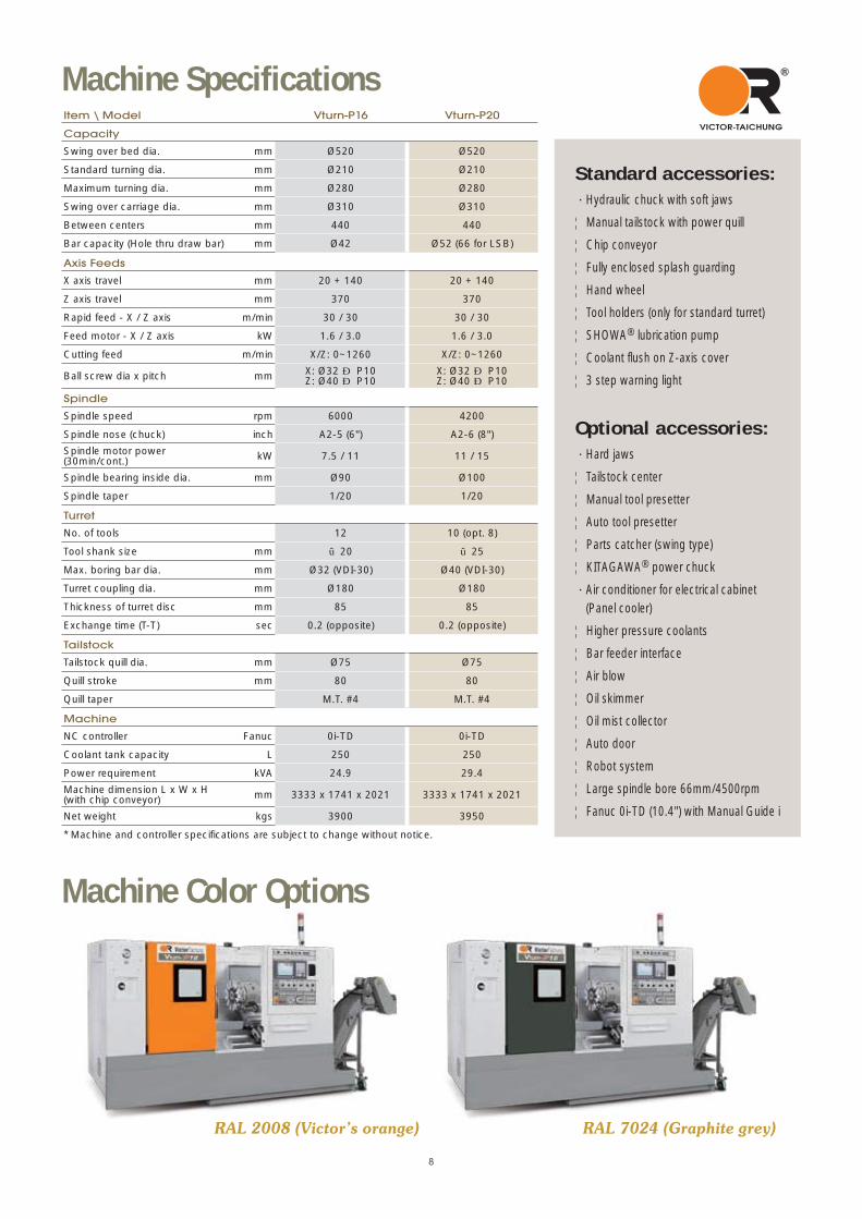
Standard accessories:Hydraulic chuck with soft jaws
‧Manual tailstock with power quill
‧Chip conveyor
‧Fully enclosed splash guarding
‧Hand wheel
‧Tool holders (only for standard turret)
‧SHOWA® lubrication pump
‧Coolant flush on Z-axis cover
‧3 step warning light
Optional accessories:Hard jaws
‧Tailstock center
‧Manual tool presetter
‧Auto tool presetter
‧Parts catcher (swing type)
‧KITAGAWA® power chuck
Air conditioner for electrical cabinet (Panel cooler)
‧Higher pressure coolants
‧Bar feeder interface
‧Air blow
‧Oil skimmer
‧Oil mist collector
‧Auto door
‧Robot system
‧Large spindle bore 66mm/4500rpm
‧Fanuc 0i-TD (10.4") with Manual Guide i
Machine Color Options
RAL 2008 (Victor’s orange) RAL 7024 (Graphite grey)
8
Item \ Model Vturn-P16 Vturn-P20
Capacity
Swing over bed dia. mm Ø520 Ø520
Standard turning dia. mm Ø210 Ø210
Maximum turning dia. mm Ø280 Ø280
Swing over carriage dia. mm Ø310 Ø310
Between centers mm 440 440
Bar capacity (Hole thru draw bar) mm Ø42 Ø52 (66 for LSB)
Axis Feeds
X axis travel mm 20 + 140 20 + 140
Z axis travel mm 370 370
Rapid feed - X / Z axis m/min 30 / 30 30 / 30
Feed motor - X / Z axis kW 1.6 / 3.0 1.6 / 3.0
Cutting feed m/min X/Z: 0~1260 X/Z: 0~1260
Ball screw dia x pitch mm X: Ø32 × P10Z: Ø40 × P10
X: Ø32 × P10Z: Ø40 × P10
Spindle
Spindle speed rpm 6000 4200
Spindle nose (chuck) inch A2-5 (6") A2-6 (8")
Spindle motor power (30min/cont.) kW 7.5 / 11 11 / 15
Spindle bearing inside dia. mm Ø90 Ø100
Spindle taper 1/20 1/20
Turret
No. of tools 12 10 (opt. 8)
Tool shank size mm □20 □25
Max. boring bar dia. mm Ø32 (VDI-30) Ø40 (VDI-30)
Turret coupling dia. mm Ø180 Ø180
Thickness of turret disc mm 85 85
Exchange time (T-T) sec 0.2 (opposite) 0.2 (opposite)
Tailstock
Tailstock quill dia. mm Ø75 Ø75
Quill stroke mm 80 80
Quill taper M.T. #4 M.T. #4
Machine
NC controller Fanuc 0i-TD 0i-TD
Coolant tank capacity L 250 250
Power requirement kVA 24.9 29.4
Machine dimension L x W x H (with chip conveyor) mm 3333 x 1741 x 2021 3333 x 1741 x 2021
Net weight kgs 3900 3950
* Machine and controller specifications are subject to change without notice.
Machine Specifications

Transformer
631
1580
100
61
1656
728
2384
945
61 4101661150
851 1294 929
245
2021
1640
5055
0
1738
863
1640530
1102255
3183
478
808
738
Technical Drawings Vturn-P16
Vturn-P20
Machine Layout
35 35
2025
20
Ø490
Ø280
Ø210
Ø185
Ø205Ø185
175 35
140 20
160
Ø32
350(X-axis stroke)
170 40 160
140 20
350
25
4035
Ø280
Ø210
Ø219
Ø249
Ø238
Ø219
Ø490
Ø40
4030
25
(X-axis stroke)
20
X-ax
is z
ero
poin
t
X-ax
is s
troke
6"Power Chuck80
MT#4
165
57.5
90
Ø75
3078
150
102
370 (Z-axis zero point)
340 (Z-axis zero point)
320 87
857 857
Stroke of quill Stroke of tailstock
140
160
135
103
150 80 320 87Stroke of quill Stroke of tailstock
8"Power Chuck
210
140
20
160
X-as
ix z
ero
poin
t
370 (Z-axis zero point)
340 (Z-axis zero point) 30
513
5X-
asix
stro
ke
7 85 7 85
Ø75
56.7 90.8
Unit: mm
9
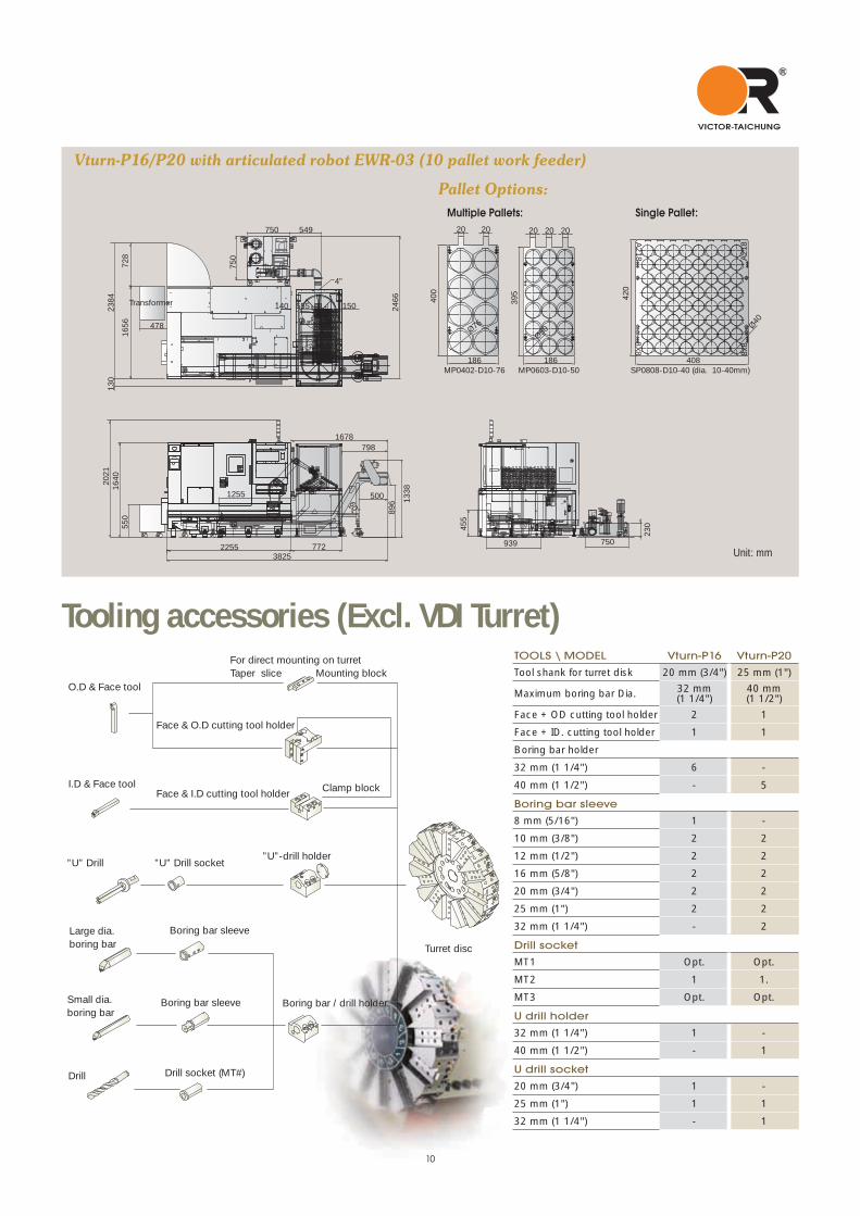
Vturn-P16/P20 with articulated robot EWR-03 (10 pallet work feeder)
4"
CE¥b�n���@���W�ø��
60 o
555140 150
3825
164020
2123
8472
8
230
750939
2466
54975075
0
896
500 1338
7981678
455
478
130
550
1656
2255
1255
772
Transformer
186
20 20
400
Ø76
395
186
202020
Ø50
408
Ø40
A218 A218
8X8 8x8
420
MP0402-D10-76 MP0603-D10-50 SP0808-D10-40 (dia. 10-40mm)
Single Pallet:
Pallet Options:
O.D & Face tool
For direct mounting on turretTaper slice Mounting block
Face & O.D cutting tool holder
Face & I.D cutting tool holder Clamp blockI.D & Face tool
Turret disc
Boring bar / drill holder
Drill socket (MT#)
Boring bar sleeve
Boring bar sleeveLarge dia.boring bar
Drill
Small dia.boring bar
”U” Drill ”U” Drill socket”U”-drill holder
Tooling accessories (Excl. VDI Turret) TOOLS \ MODEL Vturn-P16 Vturn-P20
Tool shank for turret disk 20 mm (3/4") 25 mm (1")
Maximum boring bar Dia. 32 mm (1 1/4")
40 mm (1 1/2")
Face + OD cutting tool holder 2 1
Face + ID. cutting tool holder 1 1
Boring bar holder
32 mm (1 1/4") 6 -
40 mm (1 1/2") - 5
Boring bar sleeve
8 mm (5/16") 1 -
10 mm (3/8") 2 2
12 mm (1/2") 2 2
16 mm (5/8") 2 2
20 mm (3/4") 2 2
25 mm (1") 2 2
32 mm (1 1/4") - 2
Drill socket
MT1 Opt. Opt.
MT2 1 1.
MT3 Opt. Opt.
U drill holder
32 mm (1 1/4") 1 -
40 mm (1 1/2") - 1
U drill socket
20 mm (3/4") 1 -
25 mm (1") 1 1
32 mm (1 1/4") - 1
Multiple Pallets:
Unit: mm
10

R
VictorTaichung
HTL VTL VMC HMC PIMXMT
13
05
23
01
TE
L: 0
4-2
47
33
32
6
THE COMPANIESVICTOR-TAICHUNG
Vturn-X200 Multitasking lathe Vturn-V24W for wheel turning Vturn-V560 vertical lathe
Taichung, the home of Machine Tool Manufacturing
was also marketed under the brand names (outside North America) andR
VictorTaichung GSGE12EA
profile:Sales turnover: USD 170 mil's (in 2012)*No. of employees: 1091*Exchange rate: 1 USD=30 TWD.
R
VictorTaichung
Quality Meehanite Castings-The backbone of VICTOR TAICHUNG machines.Being both ISO 9001 approved and a Meehanite cast member, our foundry produces over 1000
tons of castings a month for both our own use and export to Japan.
Modern machining facilities-65% of components manufactured in house.To ensure greater control over the quality of our machined parts, VICTOR TAICHUNG has
introduced 3 giant 5-side machining centers, 1 CIM line for sheet metal manufacturing and 2
complete FMS lines developed in house.
Overseas subsidiaries solely dedicated to service of our own products.To ensure a market for our products, VICTOR TAICHUNG has invested considerably in setting up a
global distribution network. As well as numerous agents around the world, VICTOR TAICHUNG has
8 overseas subsidiaries in USA, England, France, Germany, South Africa, Malaysia, Thailand and
China to provide our customers efficient after-sales service and technical supports.
UK Victor CNC (UK) Ltd.
TEL : 44-1-706-648485 FAX : 44-1-706-648483
FRANCE Victor France
TEL : 33-1-64772000 FAX : 33-1-64772063
GERMANY Victor GmbH
TEL : 49-2261-478434 FAX : 49-2261-478327
MALAYSIAVictor Machinery (M) SDN. BHD.
TEL : 60-3-56337180 FAX : 60-3-56337191
THAILANDVictor (Thailand) Co. Ltd.
TEL : 66-2-9263735 FAX : 66-2-9032373
INDONESIAPT. Victor Machinery Indonesia
TEL : +62-21-88958504 FAX : +62-21-88958513
USAFortune International Inc.
TEL : 1-732-2140700 FAX : 1-732-2140701
SOUTH AFRICAVictor Fortune (PTY) Ltd.
TEL : 27-11-3923800 FAX : 27-11-3923899
CHINAJianrong Precision
Machinery (Shanghai) TEL : 86-21-59768018 FAX : 86-21-59768008
TAIWAN http://www.or.com.tw E-mail :[email protected]
Victor Taichung Machinery Works Co., Ltd. Headquarters: 2088, Sec. 4, Taiwan Blvd., Taichung, Taiwan, R.O.C. TEL : 886-4-23592101 FAX : 886-4-23592943 Overseas Marketing Division: TEL : 886-4-23580701 FAX : 886-4-23584541


![D STD ]STD W T STD WXŒP ST DDDDD ...d ˙˛~q˚std˙˛ tw•p˛]std˙˛w_t˜ std˙˛wxŒp st ddddd (¤ dfid˙˛ƒtw]std˙!ƒstdddddddddddd dddddddddddddddddddddhµµµµµµµ! xstd⁄n"]std#wt˜x](https://static.documents.pub/doc/80x56/5f0a52c07e708231d42b1742/d-std-std-w-t-std-wxp-st-ddddd-d-qstd-twapstdwtoe-stdwxp.jpg)


