P1.26 GOES-13 END-TO-END INR PERFORMANCE VERIFICATION AND POST-LAUNCH TESTING Christopher Carson Boeing Space & Intelligence Systems, El Segundo CA. James L. Carr, PhD Carr Astronautics, Washington DC Chetan Sayal NASA Goddard Spaceflight Center Abstract The GOES (Geostationary Operational Environmental Satellite) system is the high altitude U.S. civilian weather satellite system comprised of an East spacecraft over the Atlantic and a West spacecraft over the eastern Pacific plus satellites stored in-orbit. Retired spacecraft are drifted further east over the Atlantic Ocean and put in service to augment coverage of South America. GOES-13, the first of the Boeing GOES N-P series, was launched in May 2006 from Cape Canaveral, Florida. Post-Launch Testing (PLT), executed by NASA with the support of the Boeing team, occurred from June 2006 through GOES-13 acceptance in December 2006. GOES-13 is presently stored in orbit. The GOES N-P series delivers improved Image Navigation and Registration (INR) performance compared to that of the previous generation. This paper describes the GOES-13 INR verification results from conceptualization through system acceptance and demonstrates the improved INR capabilities of GOES-13 that will ultimately benefit end users. Introduction GOES-13 is the first in the GOES N-P series of geostationary weather satellite built by Boeing for NASA/NOAA. The GOES N-P INR system design represents an evolution of the GOES INR architecture and an infusion of advanced spacecraft pointing technologies. Improvements for the N-P series support tighter navigation and frame- frame registration requirements. The important innovations for GOES N-P include: • Stellar Inertial Attitude Determination (SIAD) for fine attitude determination • Optical Bench accommodations for the Imager and Sounder instruments • Image Motion Compensation (IMC) implementation improvements 1
Transcript
P1.26
GOES-13 END-TO-END INR PERFORMANCE VERIFICATION AND POST-LAUNCH TESTING
Christopher Carson
Boeing Space & Intelligence Systems, El Segundo CA.
James L. Carr, PhD Carr Astronautics, Washington DC
Chetan Sayal
NASA Goddard Spaceflight Center
Abstract
The GOES (Geostationary Operational Environmental Satellite) system is the high altitude U.S. civilian weather satellite system comprised of an East spacecraft over the Atlantic and a West spacecraft over the eastern Pacific plus satellites stored in-orbit. Retired spacecraft are drifted further east over the Atlantic Ocean and put in service to augment coverage of South America. GOES-13, the first of the Boeing GOES N-P series, was launched in May 2006 from Cape Canaveral, Florida. Post-Launch Testing (PLT), executed by NASA with the support of the Boeing team, occurred from June 2006 through GOES-13 acceptance in December 2006. GOES-13 is presently stored in orbit. The GOES N-P series delivers improved Image Navigation and Registration (INR) performance compared to that of the previous generation. This paper describes the GOES-13 INR verification results from conceptualization through system acceptance and demonstrates the improved INR capabilities of GOES-13 that will ultimately benefit end users.
Introduction GOES-13 is the first in the GOES N-P series of geostationary weather satellite built by Boeing for NASA/NOAA. The GOES N-P INR system design represents an evolution of the GOES INR architecture and an infusion of advanced spacecraft pointing technologies. Improvements for the N-P series support tighter navigation and frame-frame registration requirements. The important innovations for GOES N-P include:
• Stellar Inertial Attitude Determination (SIAD) for fine attitude determination • Optical Bench accommodations for the Imager and Sounder instruments • Image Motion Compensation (IMC) implementation improvements
1
• Closed-Loop Dynamic Motion Compensation (DMC) that is added to the IMC to compensate for residual attitude control error
• INR operations to accommodate thruster maneuvers for momentum management and station-keeping
• INR operations for continuous operation across eclipses • INR operations following yaw flips
GOES-13 successfully completed Post-Launch Testing (PLT) and Image Navigation and Registration (INR) Performance Verification in December 2006. This highly successful test program, executed by the NASA/NOAA team tested the GOES-13 spacecraft through all normal and special operations, demonstrated INR performance to be more than 100% improved over the previous generation of GOES satellites and very close to next generation (GOES R) performance specifications. End-to-End INR Performance Verification began in the design phase with pure simulations using a tool called the Performance Evaluation System (PES). Closed loop testing followed with hardware-in-the-loop testing using the System Functional Test (SFT) environment and Post-Launch Testing concluded the pre-operational test of the GOES-13 system. INR system functionality and performance testing was performed after the handover of the spacecraft to the NASA PLT team following the successful Launch and Orbit Raising (LOR) phase of the mission The PLT sequence was split into two separate test activities; Activation and Characterization Testing (ACT) and Systems Operation and Performance Testing (SPOT). During the LOR phase, the spacecraft was inserted into its geostationary orbit and fully deployed with the functionality of both primary and redundant spacecraft units and all cross-strap configurations verified. At the completion of LOR, NASA assumed responsibility for spacecraft operations and commenced PLT with the beginning of the ACT. During the ACT phase all activities associated with activating the Imager/Sounder payload, Solar X-ray Imager (SXI), the Solar Environment Monitor (SEM) and the communications and T&C subsystems were performed. Additionally, characterizations of the dynamic interactions environment and the SIAD system, which would disrupt or prevent normal INR operations and assessment of INR performance, were also executed during this phase. Upon completion of the ACT phase, the Performance and Operational Testing phase began with INR startup and the buildup normal operations typical of a daily operations cadence. During this portion of PLT, the INR system was calibrated and INR specification testing was performed. Operations through a seasonal yaw flip, eclipse season, and drift operations were also demonstrated during this time period with outstanding results. The sequence of testing from launch to spacecraft acceptance is shown in Figure 1-1. A detailed description of events and performance during the INR validation is given below.
INR startup(start landmarking;INR star observations;GVAR range)
INR CalINR Cal
49
INR calibration
EW stationkeepingcycle
69
INR Spec TestINR Spec TestINR
SRSOINR
SRSO
INR rapidSuper-rapidscan test
NOAAScienceNOAA
Science
162
INRSKINRSK
169
OATS primefor orbit operations
Move s/c toPost-handoverlongitude
NSStationkeeping
(cycleInitialization)
180
HandovertoNOAA
145140
Eclipse season243 289
SeasonalYaw flip
DeployIMP(day 8)
176
Storagemode
Storagemode
Figure 1-1. Activity Phases for Post Launch Testing
INR Design Features GOES-13 INR spacecraft system design represents a marked change from the previous generation of weather spacecraft. The spacecraft features a new attitude control system approach which was motivated by tighter INR system accuracy requirements. This section highlights the key upgrades of the INR system for GOES-13 series spacecraft.
Stellar Inertial Attitude Determination (SIAD) GOES-13 features a stellar inertial attitude determination system, replacing earth sensor attitude determination used on GOES I-M. Star trackers are inherently more accurate than earth sensors. The SIAD system provides 3-axis pointing knowledge relative to an inertial reference frame. The system features 3-for-2 redundant CCD star trackers and a 2-for-1 internally redundant inertial reference unit (HIRU). Key attributes of the SIAD system are high accuracy, autonomy, speedy recovery of three-axis attitude knowledge following maneuvers and insensitivity to diurnal and seasonal effects such as sun and moon interference.
Optical Bench Imager and Sounder instruments and attitude determination sensors are mounted on a common stable optical bench, thereby controlling alignment between the star trackers and the instrument payloads and isolating the instrument thermal deformations from those of the bus. This design limits non-repeatable thermal deformation errors by limiting the thermal deformation dynamic range.
3
IMC Implementation Improvements GOES-13 maintained the onboard IMC implementation used by the previous generation spacecraft however significant performance improvements were realized by utilizing the updated electronics design. Key GOES-13 improvements include:
• Accurate scan angle prediction software utilizing precision hardware time-of-arrival measurements of Imager scan active signals
• Algorithm improvements including exact IMC computations and earth oblateness corrections for a simpler, more accurate implementation.
• Sounder IMC incorporating filter wheel position sensing to avoid degradation of channel-to-channel registration.
Closed-Loop Dynamic Motion Compensation (DMC)
The GOES I-M design compensates for rigid-body disturbances such as blackbody calibrations using an open-loop compensation method. The GOES-13 DMC closed-loop design exploits the high frequency output of the full-time gyros to sense dynamic disturbances and generate a mirror compensation signal that sums with the IMC signal for orbit and attitude. DMC attenuates pointing error from disturbances such as solar panel stepping and instrument blackbody calibration. DMC works autonomously and does not require ground calibration of spacecraft dynamic models.
Accommodation of Thruster Maneuvers Recovery of pointing accuracy following thruster maneuvers on the previous generation of GOES spacecraft is constrained by the inherent limitations of the earth sensor control system with respect to yaw sensing. Key GOES N-P system features to accommodate thruster maneuvers include:
• Nearly immediate recovery of accurate 3-axis attitude knowledge by the stellar inertial system
• Prior generation and upload of post-maneuver IMC orbit coefficients to be enabled immediately after maneuver completion
• Special ground procedures to enable rapid updating of orbit knowledge following medium and large maneuvers
Eclipse and Yaw Flip IMC In a departure from GOES IM operations, the GOES-13 primary instruments remain powered on and providing service through eclipse. Additionally, GOES-13 has the ability to perform routine semi-annual yaw flips to decrease sun loading on the instrument radiative coolers. The GOES-13 INR system includes new ground procedures to extend INR operations to these special scenarios. A special eclipse
4
period IMC set is generated daily during eclipse season using a depth of eclipse calibration table constructed from archived attitude profile solutions. A special post-flip IMC set is generated based on geometric symmetries between Imager and Sounder in the case of a first flip, and based on archived attitude solutions in the case of a subsequent flip, to predict instrument thermal profile behavior in the first 24 hours after a yaw flip.
Design and Initial Validation (PES & SFT) INR system-level verification began in the design phase using the Performance Evaluation System (PES), which is a high-fidelity event simulation of the full INR system and a contract deliverable. PES models all INR events (star sightings, landmark acquisitions, ranging, maneuvers, and ground operations) chronologically and includes embedded models of the Imager, Sounder, spacecraft attitude control and flight dynamics, and ground elements. PES error models matured during the course of system development as subsystem performance characterizations matured, so did their corresponding PES error models. Mixed-simulation testing with hardware in the loop was performed during System Functional Testing (SFT). In SFT, the space segment is represented by the Boeing Satellite Emulator (BSE), which runs the flight software on a flight-like processor and includes time domain simulations of the Imager and Sounder and the flight dynamics. BSE telemetry is ingested by the Observation Generation Software (OGS), which simulates the ground functions associated with detection of stars, acquisition of landmarks, and ranging. The operational Orbit and Attitude Tracking System (OATS), upgraded for the GOES N-P series, receives and processes the OGS data following standard INR operational protocols. SFT runs in real-time with the INR control loop closing by commanding of the BSE through the operational GOES Telemetry Acquisition and Control System (GTACS). An effort was made to coordinate PES and SFT error models so that each cross validates the other. Figure 1-2 shows a navigation error time series from PES and a comparison between three Monte Carlo runs of the PES pure-simulation and a corresponding SFT run.
Figure 1-2. PES Navigation Error Time Series (top); SFT Run and 3 Monte Carlo PES Runs
Compared (bottom) for Navigation, Frame-to-Frame (FFR), and Within Frame (WIFR) 3-σ Error Metrics
Launch and Orbit Raising (LOR) Testing Orbit raising, deployments, and bus functional checkout are all part of the LOR phase. The LOR phase was performed by Boeing at the NOAA Satellite Operations Control Center (SOCC) in Suitland, MD and consisted of an Orbit Raising period and In-Orbit Test period. During the In-Orbit Test period, which started upon reaching the handover orbit, the major deployments (solar array, magnetometer boom, and Imager/Sounder covers) were performed, the spacecraft was slewed to an earth pointed orientation and operations in Storage Mode and Normal Mode were demonstrated. The LOR phase was completed by L+22 days, and an engineering handover to NASA was performed.
Storage Mode SIAD contributions to INR performance were assessed during the Storage Mode portion of LOR. Accurate determination of HIRU Angular Random Walk (ARW) error was
6
performed during a portion of Storage Mode operations when the spacecraft was in Inertial Hold. The Boeing SIAD Characterization Tool was used to determine Star Tracker and HIRU performance and estimation of HIRU Angular Random Walk (ARW) error. The SIAD Characterization Tool is described in more detail in the PLT Payload Activation and Characterization section.
Normal Mode Entry At the conclusion of Storage Mode testing, the primary star tracker pair was powered on, and the on-board “lost-in-space” algorithm was used to autonomously determine spacecraft inertial attitude and provide an estimate of star tracker alignments sufficient to identify stars in star tracker Full Field of View (FFOV) mode. At this point the spacecraft attitude determination method was switched from sun based attitude determination to stellar inertial attitude determination. An ephemeris defining the current spacecraft orbit was uploaded to the on-board computer, and the spacecraft was commanded into Normal Mode and commanded to slew from a sun pointed attitude to an earth pointed attitude.
Calibrations, Initializations, and Checkouts in Normal Mode During Normal Mode operations, initial calibrations and checkout of all three pairs of Star Trackers are performed, a preliminary HIRU performance assessment was completed, and instruments and communications payloads were activated. Ground Based Orbit and Attitude Determination (OAD) and Momentum Dumping and Stationkeeping algorithms were then initiated and confirmed to be operating correctly.
Post Launch Test (PLT) Activation of the government furnished Imager, Sounder and SXI, INR activation, instrument calibrations, and detailed verification and characterization of spacecraft and instrument performance are the major activities performed in PLT. During PLT, a dedicated period of time is allocated to Imager and Sounder outgassing as well as for bus characterization tests and instrument calibrations. This portion of the PLT is referred to as Payload Activation and Characterization Testing (ACT). The Imager and Sounder cooler covers were deployed at the end of their outgassing period. The critical portion of PLT, Systems Performance and Operational Testing (SPOT), included INR operations startup and spacecraft system operations initialization. Overall INR performance was assessed during SPOT as well as the ability to perform typical seasonal activities, such as yaw flip and eclipse operations. Additionally, instrument performance trending occurred during this phase.
7
Payload Activation and Characterization Testing (ACT) In addition to quiescent Imager and Sounder outgassing operations, early Payload Activation and Characterization Testing comprised of five significant activities related to INR which were completed prior to starting normal daily operations. These activities are described in the following paragraphs.
Assessment of Spacecraft Contributions to the INR Budget Characterization of spacecraft performance was executed to verify that the INR error contributions were at expected levels. Characterization of dynamic interactions and final alignment calibrations and tuning were performed on the Star Trackers.. Star Tracker Fine Alignment and Kalman Filter Tuning Star Tracker Fine Alignment (SFA) improves on the preliminary star tracker alignment that was performed during the LOR phase. The alignment process makes the ST measurements from the calibrated tracker combination self-consistent, thereby allowing directed field-of-view (DFOV) operations and minimizing SIAD thrashing (an effect that occurs when the number of stars tracked by each tracker changes, causing the weighting between tracker misalignments to change and therefore the attitude estimate). An additional collection period, for each tracker pair combination was used to collect star tracker residual telemetry, which is used by the Kalman Filter Statistics calibration algorithm to compute updated values for the SIAD Kalman Filter measurement variances, which tune Kalman Filter performance. Figures 1-3 shows typical results displays generated by the Boeing SFA / KFS tool for Star Tracker Alignment and Kalman Filter tuning.
Figure 1-3. Typical SFA / KFS Tool Displays for ST Alignment, Kalman Filter Tuning
Star Tracker and HIRU Performance Characterization An initial performance estimate of the star tracker and HIRU was performed in the LOR phase. The Boeing provided SIAD Characterization Tool was used to determine Star Tracker and HIRU performance. Star and Kalman filter residual telemetry over a selected period was used as the input to the SIAD tool for calculating Star Tracker
8
performance. The SIAD tool estimates High Spatial Frequency (HSF) and Low Spatial Frequency (LSF) errors and errors in knowledge of boresight separation between the two trackers, determines HSF and LSF error dependence on star magnitude, and estimates Temporal Noise (TN) errors. Typical results of Star Tracker performance monitoring calculations for HSF, LSF, and tracker-to-tracker boresight separation generated by the SIAD tool are shown in Figure 1-4.
Figure 1-4. SIAD Characterization Tool Typical ST HSF and LSF Estimate Results
Characterization of the HIRU required two periods of data collection. Estimation of HIRU Angular Random Walk (ARW) error was performed while the spacecraft was in storage mode and inertially held. Angular White Noise (AWN) error determination, which required high rate collection of raw angle data, was performed during Normal Mode operations. The SIAD tool estimated ARW and AWN by applying Power Spectrum Density (PSD) analysis to the collected HIRU raw gyro angle and time tagged data. Examples of ARW and AWN estimates output by the SIAD tool are displayed in Figure 1-5.
9
Figure 1-5. SIAD Characterization Tool Typical ARW and AWN Results
Dynamic Interaction Testing (DIT) The effect of various spacecraft disturbance sources on spacecraft bus and Instrument pointing was characterized in a series of Dynamic Interaction Tests (DITs). Each DIT characterized the effect of a specific disturbance source on spacecraft pointing, rates, acceleration and jitter, estimated spacecraft bus attitude error telemetry, and Angular Velocity Sensor (AVS) data during and after the time during which the disturbance occurs. These tests included:
• SAD, XRP, SXI disturbance tests during which the SAD, XRP, and SXI are commanded to offsets which represent the full range of motion expected during Normal Mode operations, and slews of SAD and XRP are performed at various stepping rates to determine effect on spacecraft pointing and jitter
• SAD stutter stepping characterization tests which examined the effects of a wide range of stutter stepping cadences to determine the optimal stutter stepping design to minimize bus and Instrument jitter
• RWA disturbance characterization tests which, in addition to measuring pointing and jitter due to nominal daily RWA operations, would temporarily modify wheel speed biases in order to induce wheel speed zero crossings and increase the daily range of wheel speeds; these tests characterized the disturbances due to wheel zero-speed crossings in the event 3-wheel operations would become necessary and determined maximum wheel speeds for which disturbances remain within acceptable levels
10
• Characterization of jitter and pointing errors during and immediately following the daily momentum dump.
• Characterization of pointing and jitter during and immediately following various types of Imager mirror motion and in the presence of filter wheel disturbances
DIT results were compared against predicted / budgeted allocations for disturbance induced pointing errors and jitter, and were used to determine overall spacecraft disturbance contributions to the INR budget. IMC and DMC Characterization Image Motion Compensation (IMC) and Dynamic Motion Compensation (DMC) characterization occurred during this phase of PLT. The error in the computation of the IMC is based on the Boeing provided IMC/DMC tool. The tool collects telemetry of applied IMC signal and compares it to a calculation of ideal IMC. The IMC/DMC tool also assesses the magnitude and phase difference between the Imager DMC output and the S/C motion sensed by an Angular Velocity Sensor (AVS). Examples of output from IMC/DMC tool are provided in Figure 1-6.
Figure 1-6. IMC/DMC Tool Typical Results
11
System Performance and Operational Testing (SPOT) Evaluation of overall system performance during the course of typical day-to-day operations, as well as calibration and trending of INR performance occurred during the SPOT phase. Start up and calibration of the ground INR system initiates this Performance and Operational Testing period in which the majority of the PLT period was spent. Once INR startup and calibration was complete, determination of overall INR performance during normal operations began. The Performance and Operational Testing period encompassed INR performance operations through one eclipse season and a yaw flip sequence. Additionally, a number of other spacecraft capabilities were tested including entry into and return from storage mode, as well as station change operations. These activities are described in more detail below:
INR Start Up & Calibration / Imager Boresight Alignment Determination INR Startup initiates the semi-closed loop process of using INR observation data (landmarks, stars, and S/C range) in the ground Orbit and Attitude Tracking System (OATS) to achieve knowledge and repeatability of the Imager and Sounder attitude profiles and the spacecraft orbit from an initially unknown attitude state and an externally determined orbit state provided by the Flight Dynamics group. Additionally, the mean Imager/Sounder boresight attitude relative to the Star Tracker Assembly is determined and removed in the ground system, effectively re-defining Imager and Sounder nadir. A characterization of the effect of star tracker attitude variations on Imager instrument attitude using Star Measurement Comparison tool developed by Boeing was also performed during this calibration period. This tool uses INR ground system generated Imager instrument attitude information over the course of a day and star tracker residual telemetry to provide comparison plots of star tracker and instrument attitudes. Examples of output from Star Measurement Comparison tools are provided in Figure1-7.
Figure 1-7. Star Measurement Comparison Tool Typical Results
12
Other calibrations include assessing the optimal fit orders for each of the five attitude terms for the Imager and Sounder, the error associated with the OATS ability to determine orbit using landmarks and S/C range information and the error associated with the ground computed delta-V for all maneuvers. INR Spec Testing Evaluation of overall INR performance by NASA, using INR ground system generated landmark residual based metrics as interpreted by the government developed Performance Assessment System (PAS) occurred during the normal mode specification period, during Yaw Flip Operations, Eclipse Operations and Stationkeeping and Station change maneuvers. Normal Operations Checkout INR system level performance was evaluated for all INR categories of navigation. The statistics were gathered during the period between spacecraft stationkeeping maneuvers, where operations were performed based on a daily normal operations timeline. The performance was measured as the percentage of observations that fell within the specification in the given category. To meet the INR requirements 99.7% of the sample data had to meet the requirement. GOES-13 met all of its observational requirements for the normal operations period as shown in Table 1-1. Figures 1-8, 1-9 and 1-10 show the landmark observations for the navigation, frame to frame and the within frame specifications for the entire 46 day specification testing period. Figure 1-11 shows the corresponding data from GOES-12 for the same data span. It is evident from Figures 1-8 and 1-11 that GOES-13 INR performance is improved over 100% from that of GOES-12. The data collection period occurred during eclipse season and thus eclipse data was excluded against the measurement of normal operations specification compliance.
Frame to Frame Navigation Within Frame
15 mins 90 mins 24 hrs EW NS EW NS EW NS EW NS EW NS
Table 1-1 GOES-13 INR Normal Operations Specification Results
13
Figure 1-8. GOES-13 INR Normal Operations Navigation Performance Results
Figure 1-9. GOES-13 INR Normal Operations Frame to Frame Performance Results
Figure 1-10. GOES-13 INR Normal Operations Within Frame Performance Results
14
Figure 1-11. GOES-12 INR Normal Operations Navigation Performance Results
Seasonal Yaw Flip During PLT GOES-13 operated through the autumnal eclipse period. In order to keep the sun on the –Y side of the spacecraft, a yaw flip was performed immediately prior to the start of eclipse season. During these periods, as seen in Figures 1-12 and 1-13 imaging operations continued during the yaw flip recovery period and returned to full normal operations performance levels following the recovery.
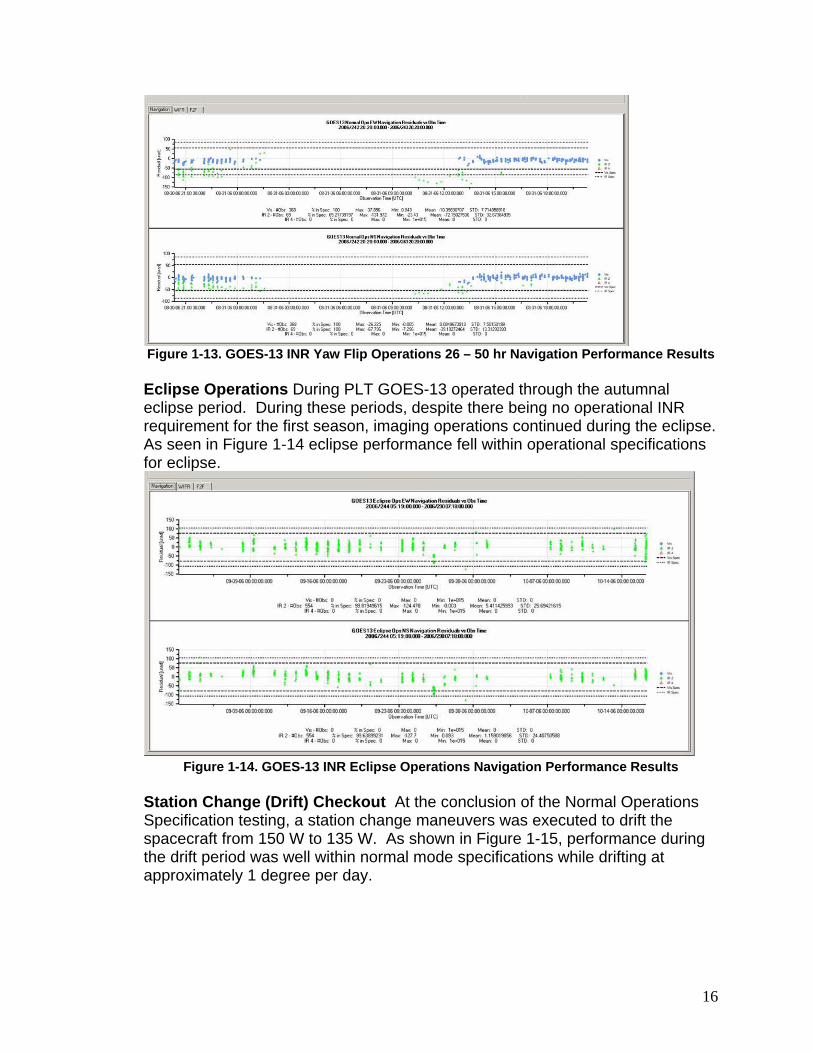
Figure 1-13. GOES-13 INR Yaw Flip Operations 26 – 50 hr Navigation Performance Results Eclipse Operations During PLT GOES-13 operated through the autumnal eclipse period. During these periods, despite there being no operational INR requirement for the first season, imaging operations continued during the eclipse. As seen in Figure 1-14 eclipse performance fell within operational specifications for eclipse.
Station Change (Drift) Checkout At the conclusion of the Normal Operations Specification testing, a station change maneuvers was executed to drift the spacecraft from 150 W to 135 W. As shown in Figure 1-15, performance during the drift period was well within normal mode specifications while drifting at approximately 1 degree per day.
Conclusions GOES-13 is the first spacecraft in the GOES NOP series representing an evolution of the heritage GOES INR architecture incorporating advanced spacecraft pointing technologies (SIAD, DMC, an optical bench, and an improved IMC implementation) and new ground algorithms to support eclipse, thruster, and yaw-flip operations. System-level INR verification began in the design phase using the high fidelity PES simulator, followed by hardware-in-the-loop testing in SFT, and finally concluded in flight during PLT. Each verification step built confidence for the next step, and concluded with a robust spacecraft system that is ready for long-term operational service and complies with all system level INR specifications. The GOES N-P generation delivers substantial improvement in INR over the previous generation as evident from the very successful PLT phase. PLT was an intensive effort lasting about six months. A thorough battery of engineering and subsystems tests led up to INR specification testing, during which the entire system was operated as it would normally be in routine service. For all INR requirements pertaining to normal operations, INR specification compliance greater than 99.7% was achieved. The benefits of GOES-13 INR performance to the user community were demonstrated during the science testing portion of PLT. A side-by-side movie loop comparison between the legacy GOES system and GOES-13 is found at http://cimss.ssec.wisc.edu/goes/blog/archives/date/2006/12.1 This demonstration clearly shows the enhanced quality of service that is available a higher percentage of the available mission time than ever before, thanks to the ability to operate through eclipses and improved recovery after station-keeping maneuvers and yaw flips.