8
MFP14 Automatic pumps for condensate and other industrial fluids
MFP14 Automatic pumpsfor condensate and other
industrial fluids
2
Effective condensate management ...an essential part of any steam plantIf energy requirements are to be kept to a minimum, then efficient handling of condensate is essential to optimise plant efficiency and product quality. Spirax Sarco offers the solutions to achieve this efficiency in all areas of condensate pumping.
Condensate Management covers two separate key areas:
Condensate removalCondensate removal from all heat exchange and process equipment is necessary to provide stable operating conditions, giving improved efficiency and prolonging equipment life.
Efficient condensate removal prevents: Unstable temperature control.Product quality problems.Excessive corrosion of heating surfaces.Waterhammer.Noisy operation.Equipment damage.
Condensate recoveryWhen condensate leaves the steam trap it has approximately 20% of the original heat energy contained within the steam.
Recovering and returning this valuable energy source saves:
Heat energy - saving fuel.Expensive water treatment chemicals.High feedwater make-up costs.
All too often these problems have been neglected because no fully engineered system was readily available.
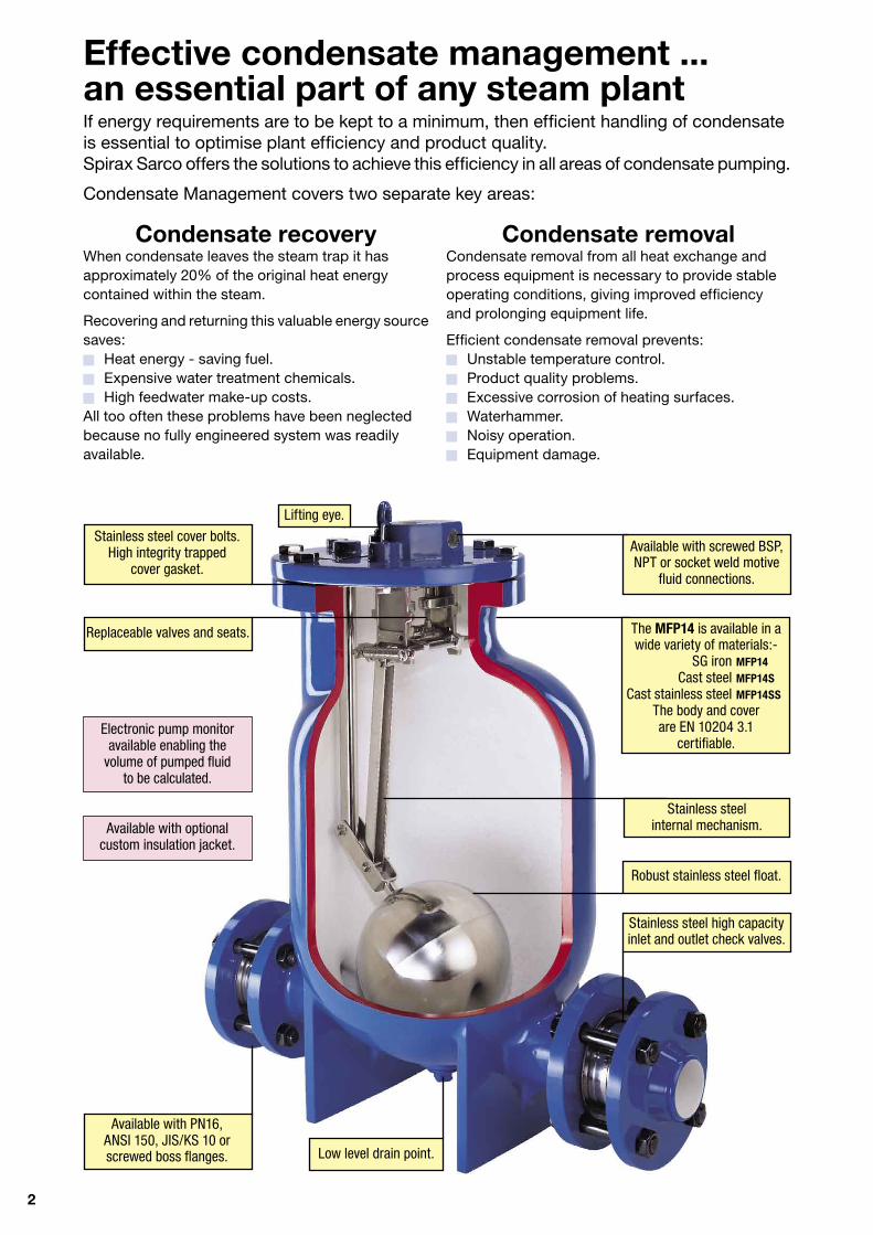
Stainless steel high capacity inlet and outlet check valves.
Robust stainless steel float.
Low level drain point.
Available with PN16, ANSI 150, JIS/KS 10 or screwed boss flanges.
Electronic pump monitor available enabling the
volume of pumped fluid to be calculated.
Available with optionalcustom insulation jacket.
Available with screwed BSP, NPT or socket weld motive
fluid connections.
Stainless steel cover bolts. High integrity trapped
cover gasket.
Replaceable valves and seats.
Stainless steel internal mechanism.
The MFP14 is available in a wide variety of materials:-
SG iron MFP14 Cast steel MFP14S Cast stainless steel MFP14SS
The body and cover are EN 10204 3.1
certifiable.
Lifting eye.

3
The total solutionSpirax Sarco’s range of MFP14 automatic pumps are specifically designed to remove and recover condensate under all operating conditions and provide the unique opportunity to solve all condensate handling problems.
The pumps are self-contained units using steam or other pressurised gas as their motive power.There are no electric motors or level switches, simplifying installation and making it ideal for hazardous areas.
One pump design covers all applications from vacuum systems to general condensate return.MFP14 automatic pumps are able to pump high temperature fluids without cavitation, reducing plant maintenance problems. They are also well suited to pump other industrial fluids including contaminated water, oils, and some hydrocarbon condensates.
Nominal capacity with 8 bar g operating pressure and 1 bar g back pressure
Range and options
User benefits ● Removes condensate under all load conditions, even vacuum, ensuring maximum process efficiency.
● Requires no electrical power - suitable for hazardous environments.
● Cavitation problems eliminated reducing maintenance.
● No mechanical seals or packing glands to leak.
● Effective design provides high capacity in a rugged, compact package.
● Available in a range of materials, sizes and end connections to suit a wide variety of applications.
● Spirax Sarco's guarantee of worldwide technical support, knowledge and service.
Size
Pump type MFP14 MFP14S MFP14SS
Body material EN-GJS-400-18-LT GSC 25N / BS EN 10213-4
ASTM A216 WCB ASTM A351 CF3M
Body design rating PN16 PN16 PN16
DN25 1" ●
DN40 1½" ●
DN50 2" ● ● ●
DN80 3 " inlet DN50 2" outlet
●
PN16 ● ● ●
Flanged ANSI 150 ● ● ●
JIS/KS 10 ● ● ●
Screwed BSP ● ● ●
BSP ● ● ●
Screwed
NPT ● ● ●
Socket weld ● ●
Stainless steel internal mechanism ● ● ●
Maximum operating pressure 13.8 bar g
Maximum operating temperature 200°C
Inle
t / O
utle
tCo
nnec
tions
Mot
ive
fluid
Conn
ectio
ns
Material SG iron Steel Stainless steel
DN25 DN40 DN50 DN80 inlet x DN50 outlet 1" 1½" 2" 3" inlet x 2" outlet
1 100 kg/h 1 800 kg/h 3 200 kg/h 5 500 kg/h
4
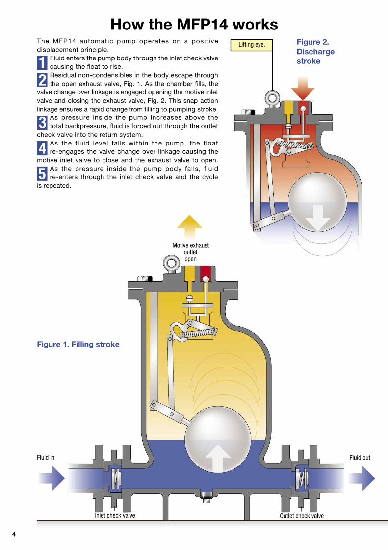
How the MFP14 worksThe MFP14 automatic pump operates on a positive displacement principle.
Fluid enters the pump body through the inlet check valvecausing the float to rise.Residual non-condensibles in the body escape through the open exhaust valve, Fig. 1. As the chamber fills, the
valve change over linkage is engaged opening the motive inlet valve and closing the exhaust valve, Fig. 2. This snap action linkage ensures a rapid change from filling to pumping stroke.
As pressure inside the pump increases above thetotal backpressure, fluid is forced out through the outlet
check valve into the return system.As the fluid level falls within the pump, the float re-engages the valve change over linkage causing the
motive inlet valve to close and the exhaust valve to open.As the pressure inside the pump body falls, fluidre-enters through the inlet check valve and the cycle
is repeated.
12
3
4
5
Lifting eye.
Fluid in Fluid out
Figure 2.Discharge stroke
Figure 1. Filling stroke
Motive exhaust outlet open
Outlet check valveInlet check valve

5
Typical applications
Condensatecollectingreceiver
Floattrap
Pump
Condensate collecting receiver
Airvent
FloattrapPump
** A soft seated check valve should be fitted to prevent ingress of air
Heat exchanger
Condensate removal from vacuum equipmentSimple and efficient solution to a difficult problem without the need for expensive electrical pumps and sensors.
Condensate recovery (open system)Pumping high temperature condensate without
cavitation or mechanical seal problems. Provides maximum heat energy recovery.
Condensate removal from process vessels and heat exchangers(pump/trap combination, closed system)
Removal of condensate under all pressure conditions ensures stable temperatures. It also prevents bottom end tube corrosion and potential waterhammer and freezing.
Vacuum heatexchanger / receiver
Float trapPump
6
14
12
10
8
6
4
2
01 000 2 000 3 000 4 000 5 000 6 000
14
12
10
8
6
4
2
00 400 800 1 200 1 600 2 000
How to size and select the MFP14
Considering the inlet pressure, backpressure and filling head conditions, select the pump size which meets the capacity requirements of the application.
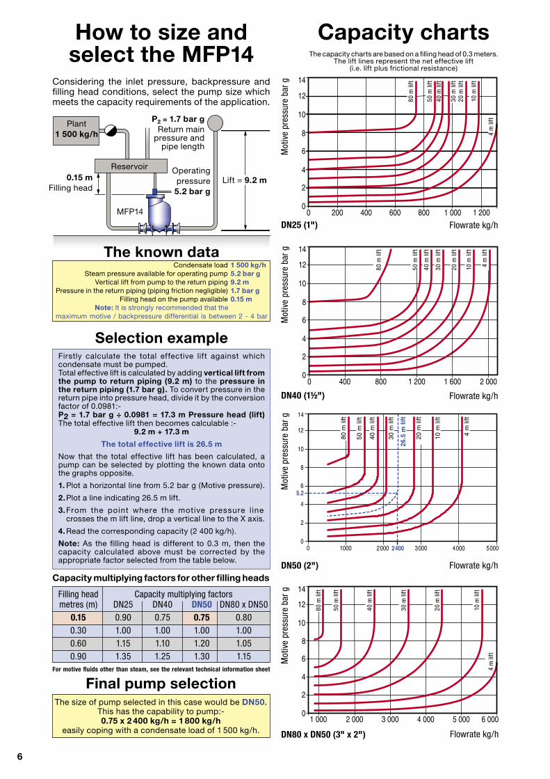
Capacity charts
Final pump selectionThe size of pump selected in this case would be DN50.
This has the capability to pump:- 0.75 x 2 400 kg/h = 1 800 kg/h
easily coping with a condensate load of 1 500 kg/h.
The known data Condensate load 1 500 kg/h Steam pressure available for operating pump 5.2 bar g Vertical lift from pump to the return piping 9.2 m Pressure in the return piping (piping friction negligible) 1.7 bar g Filling head on the pump available 0.15 m
Note: It is strongly recommended that the maximum motive / backpressure differential is between 2 - 4 bar
Selection exampleFirstly calculate the total effective lift against which condensate must be pumped.Total effective lift is calculated by adding vertical lift from the pump to return piping (9.2 m) to the pressure in the return piping (1.7 bar g). To convert pressure in the return pipe into pressure head, divide it by the conversion factor of 0.0981:-P2 = 1.7 bar g ÷ 0.0981 = 17.3 m Pressure head (lift)The total effective lift then becomes calculable :-
9.2 m + 17.3 m
The total effective lift is 26.5 m
Now that the total effective lift has been calculated, a pump can be selected by plotting the known data onto the graphs opposite.
1. Plot a horizontal line from 5.2 bar g (Motive pressure).
2. Plot a line indicating 26.5 m lift.
3. From the point where the motive pressure l ine crosses the m lift line, drop a vertical line to the X axis.
4. Read the corresponding capacity (2 400 kg/h).
Note: As the filling head is different to 0.3 m, then the capacity calculated above must be corrected by the appropriate factor selected from the table below.
Capacity multiplying factors for other filling heads
Filling head Capacity multiplying factors metres (m) DN25 DN40 DN50 DN80 x DN50 0.15 0.90 0.75 0.75 0.80 0.30 1.00 1.00 1.00 1.00 0.60 1.15 1.10 1.20 1.05 0.90 1.35 1.25 1.30 1.15For motive fluids other than steam, see the relevant technical information sheet
P2 = 1.7 bar gReturn main
pressure andpipe length
Lift = 9.2 m0.15 mFilling head
MFP14
Reservoir
Plant 1 500 kg/h
Flowrate kg/hDN80 x DN50 (3" x 2")
DN50 (2")
Mot
ive
pres
sure
bar
g
����
�����
����
�����
����
�����
����
�����
����
�����
����
�����
���
�����
����
�����
��
��
�
�
�
�
��
��
��
���
���� ���� ���� ���� ��������
Flowrate kg/h
Mot
ive
pres
sure
bar
g
Flowrate kg/hDN40 (1½")
Mot
ive
pres
sure
bar
g
14
12
10
8
6
4
2
00 200 400 600 800 1 000 1 200
Flowrate kg/hDN25 (1")
Mot
ive
pres
sure
bar
g
The capacity charts are based on a filling head of 0.3 meters. The lift lines represent the net effective lift
(i.e. lift plus frictional resistance)
50 m
lift
40 m
lift
30 m
lift
20 m
lift
10 m
lift
4 m
lift
4 m
lift
80 m
lift
10 m
lift
40 m
lift
50 m
lift
20 m
lift
10 m
lift
4 m
lift
30 m
lift
40 m
lift
50 m
lift
80 m
lift
Operatingpressure5.2 bar g
30 m
lift
20 m
lift
80 m
lift
7
Percentage load
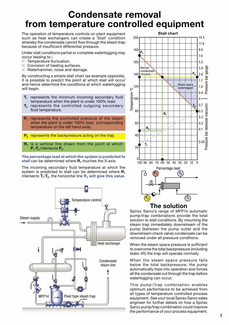
Condensate removal from temperature controlled equipment
The operation of temperature controls on plant equipment such as heat exchangers can create a 'Stall' condition whereby the condensate cannot flow through the steam trap because of insufficient differential pressure.
Under stall conditions partial or complete waterlogging may occur leading to:- Temperature fluctuation. Corrosion of heating surfaces. Waterhammer, noise and damage.
By constructing a simple stall chart (as example opposite), it is possible to predict the point at which stall will occur and hence determine the conditions at which waterlogging will begin.
T1 represents the minimum incoming secondary fluid temperature when the plant is under 100% load.T2 represents the controlled outgoing secondary fluid temperature.
P1 represents the controlled pressure of the steam when the plant is under 100% load (corresponding temperature on the left hand axis).
P2 represents the backpressure acting on the trap.
R1 is a vertical line drawn from the point at which P1-T2 intersects P2.
The percentage load at which the system is predicted to stall can be determined where R1 touches the X-axis.
The incoming secondary fluid temperature at which the system is predicted to stall can be determined where R1 intersects T1-T2, the horizontal line R2 will give this value.
The solutionSpirax Sarco’s range of MFP14 automatic pump/trap combinations provide the total solution to stall conditions. By mounting the steam trap immediately downstream of the pump (between the pump outlet and the downstream check valve) condensate can be removed under all pressure conditions. When the steam space pressure is sufficient to overcome the total backpressure (including static lift) the trap will operate normally. When the steam space pressure fal ls below the total backpressure, the pump automatically trips into operation and forces all the condensate out through the trap before waterlogging can occur. This pump / trap combination enables optimum performance to be achieved from all types of temperature controlled process equipment. See your local Spirax Sarco sales engineer for further details on how a Spirax Sarco pump/trap combination could improve the performance of your process equipment.
Temperature control
Float type steam trap
Heat exchanger
Steam supply
Condensate return line
MFP14
Steam spacewaterlogged
P1
P2
R1
100 90 80 70 60 50 40 30 20 10 0
200
180
160
140
120
100
80
60
40
20
0
Tem
pera
ture
°C
14.5
11.6
9.0
7.0
5.2
3.8
2.6
1.7
1.0
0.4
0
0.7
0.5
0.3
0.2
0.1
0.05
Stall chart
Normalcondensateremoval
R2
T1
T2
Pres
sure
bar
abs
olut
e (v
acuu
m)
Pres
sure
bar
gau
ge
P1 T2
T1P2
MFP14SG iron
D
C
Integral lifting eye 15 mm diameter
FE
A
B
*Weights inclusive of check valves and flanges
MFP14SSteel
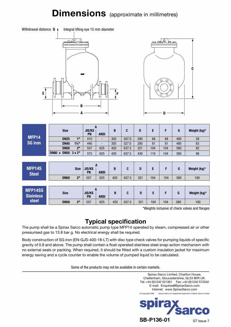
Withdrawal distance G
Dimensions (approximate in millimetres)
Some of the products may not be available in certain markets.
Typical specificationThe pump shall be a Spirax Sarco automatic pump type MFP14 operated by steam, compressed air or other pressurised gas to 13.8 bar g. No electrical energy shall be required.
Body construction of SG iron (EN-GJS-400-18-LT) with disc type check valves for pumping liquids of specific gravity of 0.8 and above. The pump shall contain a float operated stainless steel snap-action mechanism with no external seals or packing. When required, it should be fitted with a custom insulation jacket for maximum energy saving and a cycle counter to enable the volume of pumped liquid to be calculated.
MFP14SSStainless
steel
Spirax-Sarco Limited, Charlton House,Cheltenham, Gloucestershire, GL53 8ER UK.
Tel: +44 (0)1242 521361 Fax: +44 (0)1242 573342E-mail: [email protected]
Internet: www.SpiraxSarco.com© Copyright 2008 Spirax Sarco is a registered trademark of Spirax-Sarco Limited
SB-P136-01 ST Issue 7
A Size JIS/KS B C D E F G Weight (kg)* PN ANSI
DN50 2" 557 625 420 637.5 321 104 104 580 100
A Size JIS/KS B C D E F G Weight (kg)* PN ANSI
DN50 2" 557 625 420 637.5 321 104 104 580 100
A Size JIS/KS B C D E F G Weight (kg)* PN ANSI DN25 1" 410 - 305 507.0 280 68 68 480 58 DN40 1½" 440 - 305 527.0 280 81 81 480 63 DN50 2" 557 625 420 637.5 321 104 104 580 82 DN80 x DN50 3 x 2" 573 625 420 637.5 430 119 104 580 98