P837/D11, January 2013 Draft Standard for Qualifying Permanent Connections Used on Substation Grounding
Notice and Disclaimer of Liability Concerning the Use of IEEE Documents: IEEE Standards documents are developed 1 within the IEEE Societies and the Standards Coordinating Committees of the IEEE Standards Association (IEEE-SA) 2 Standards Board. IEEE develops its standards through a consensus development process, approved by the American National 3 Standards Institute, which brings together volunteers representing varied viewpoints and interests to achieve the final product. 4 Volunteers are not necessarily members of the Institute and serve without compensation. While IEEE administers the process 5 and establishes rules to promote fairness in the consensus development process, IEEE does not independently evaluate, test, or 6 verify the accuracy of any of the information or the soundness of any judgments contained in its standards. 7
Use of an IEEE Standard is wholly voluntary. IEEE disclaims liability for any personal injury, property or other damage, of 8 any nature whatsoever, whether special, indirect, consequential, or compensatory, directly or indirectly resulting from the 9 publication, use of, or reliance upon any IEEE Standard document. 10
IEEE does not warrant or represent the accuracy or content of the material contained in its standards, and expressly disclaims 11 any express or implied warranty, including any implied warranty of merchantability or fitness for a specific purpose, or that 12 the use of the material contained in its standards is free from patent infringement. IEEE Standards documents are supplied "AS 13 IS." 14
The existence of an IEEE Standard does not imply that there are no other ways to produce, test, measure, purchase, market, or 15 provide other goods and services related to the scope of the IEEE standard. Furthermore, the viewpoint expressed at the time a 16 standard is approved and issued is subject to change brought about through developments in the state of the art and comments 17 received from users of the standard. Every IEEE standard is subjected to review at least every ten years. When a document is 18 more than ten years old and has not undergone a revision process, it is reasonable to conclude that its contents, although still of 19 some value, do not wholly reflect the present state of the art. Users are cautioned to check to determine that they have the 20 latest edition of any IEEE standard. 21
In publishing and making its standards available, IEEE is not suggesting or rendering professional or other services for, or on 22 behalf of, any person or entity. Nor is IEEE undertaking to perform any duty owed by any other person or entity to another. 23 Any person utilizing any IEEE Standards document, should rely upon his or her own independent judgment in the exercise of 24 reasonable care in any given circumstances or, as appropriate, seek the advice of a competent professional in determining the 25 appropriateness of a given IEEE standard. 26
Translations: The IEEE consensus development process involves the review of documents in English only. In the event that 27 an IEEE standard is translated, only the English version published by IEEE should be considered the approved IEEE standard. 28
Official Statements: A statement, written or oral, that is not processed in accordance with the IEEE-SA Standards Board 29 Operations Manual shall not be considered the official position of IEEE or any of its committees and shall not be considered to 30 be, nor be relied upon as, a formal position of IEEE. At lectures, symposia, seminars, or educational courses, an individual 31 presenting information on IEEE standards shall make it clear that his or her views should be considered the personal views of 32 that individual rather than the formal position of IEEE. 33
Comments on Standards: Comments for revision of IEEE Standards documents are welcome from any interested party, 34 regardless of membership affiliation with IEEE. However, IEEE does not provide consulting information or advice pertaining 35 to IEEE Standards documents. Suggestions for changes in documents should be in the form of a proposed change of text, 36 together with appropriate supporting comments. Since IEEE standards represent a consensus of concerned interests, it is 37 important to ensure that any responses to comments and questions also receive the concurrence of a balance of interests. For 38 this reason, IEEE and the members of its societies and Standards Coordinating Committees are not able to provide an instant 39 response to comments or questions except in those cases where the matter has previously been addressed. Any person who 40 would like to participate in evaluating comments or revisions to an IEEE standard is welcome to join the relevant IEEE 41 working group at http://standards.ieee.org/develop/wg/. 42
Comments on standards should be submitted to the following address: 43
Secretary, IEEE-SA Standards Board 44 445 Hoes Lane 45 Piscataway, NJ 08854 46 USA 47
Photocopies: Authorization to photocopy portions of any individual standard for internal or personal use is granted by The 48 Institute of Electrical and Electronics Engineers, Inc., provided that the appropriate fee is paid to Copyright Clearance Center. 49 To arrange for payment of licensing fee, please contact Copyright Clearance Center, Customer Service, 222 Rosewood Drive, 50 Danvers, MA 01923 USA; +1 978 750 8400. Permission to photocopy portions of any individual standard for educational 51 classroom use can also be obtained through the Copyright Clearance Center. 52
This is an unapproved IEEE Standards Draft, subject to change.
iv
Notice to users 1
Laws and regulations 2
Users of IEEE Standards documents should consult all applicable laws and regulations. Compliance with 3 the provisions of any IEEE Standards document does not imply compliance to any applicable regulatory 4 requirements. Implementers of the standard are responsible for observing or referring to the applicable 5 regulatory requirements. IEEE does not, by the publication of its standards, intend to urge action that is not 6 in compliance with applicable laws, and these documents may not be construed as doing so. 7
Copyrights 8
This document is copyrighted by the IEEE. It is made available for a wide variety of both public and 9 private uses. These include both use, by reference, in laws and regulations, and use in private self-10 regulation, standardization, and the promotion of engineering practices and methods. By making this 11 document available for use and adoption by public authorities and private users, the IEEE does not waive 12 any rights in copyright to this document. 13
Updating of IEEE documents 14
Users of IEEE Standards documents should be aware that these documents may be superseded at any time 15 by the issuance of new editions or may be amended from time to time through the issuance of amendments, 16 corrigenda, or errata. An official IEEE document at any point in time consists of the current edition of the 17 document together with any amendments, corrigenda, or errata then in effect. In order to determine whether 18 a given document is the current edition and whether it has been amended through the issuance of 19 amendments, corrigenda, or errata, visit the IEEE-SA Website at http://standards.ieee.org/index.html or 20 contact the IEEE at the address listed previously. For more information about the IEEE Standards 21 Association or the IEEE standards development process, visit IEEE-SA Website at 22 http://standards.ieee.org/index.html. 23
Errata 24
Errata, if any, for this and all other standards can be accessed at the following URL: 25 http://standards.ieee.org/findstds/errata/index.html. Users are encouraged to check this URL for errata 26 periodically. 27
Patents 28
Attention is called to the possibility that implementation of this standard may require use of subject matter 29 covered by patent rights. By publication of this standard, no position is taken by the IEEE with respect to 30 the existence or validity of any patent rights in connection therewith. If a patent holder or patent applicant 31 has filed a statement of assurance via an Accepted Letter of Assurance, then the statement is listed on the 32 IEEE-SA Website at http://standards.ieee.org/about/sasb/patcom/patents.html. Letters of Assurance may 33 indicate whether the Submitter is willing or unwilling to grant licenses under patent rights without 34 compensation or under reasonable rates, with reasonable terms and conditions that are demonstrably free of 35 any unfair discrimination to applicants desiring to obtain such licenses. 36
Essential Patent Claims may exist for which a Letter of Assurance has not been received. The IEEE is not 37 responsible for identifying Essential Patent Claims for which a license may be required, for conducting 38 inquiries into the legal validity or scope of Patents Claims, or determining whether any licensing terms or 39 conditions provided in connection with submission of a Letter of Assurance, if any, or in any licensing 40 agreements are reasonable or non-discriminatory. Users of this standard are expressly advised that 41 determination of the validity of any patent rights, and the risk of infringement of such rights, is entirely 42 their own responsibility. Further information may be obtained from the IEEE Standards Association. 43
This is an unapproved IEEE Standards Draft, subject to change.
vi
Participants 1
At the time this draft standard was completed, the E9 Working Group had the following membership: 2
David Kelley, Chair 3 Brian Story, Vice Chair 4
5 Participant1 6 Participant2 7 Participant3 8
Participant4 9 Participant5 10 Participant6 11
Participant7 12 Participant8 13 Participant9 14
15
The following members of the <individual/entity> balloting committee voted on this standard. Balloters 16 may have voted for approval, disapproval, or abstention. 17
[To be supplied by IEEE] 18
Balloter1 19 Balloter2 20 Balloter3 21
Balloter4 22 Balloter5 23 Balloter6 24
Balloter7 25 Balloter8 26 Balloter9 27
28
When the IEEE-SA Standards Board approved this standard on <Date Approved>, it had the following 29 membership: 30
4. Qualification Tests...................................................................................................................................... 3 8 a See Annex D for additional information ...................................................................................................... 4 9
6. Test Procedures .......................................................................................................................................... 8 14 6.1 General ................................................................................................................................................ 8 15 6.2 Mechanical Test Samples .................................................................................................................... 9 16 6.3 Sequential Test Samples ...................................................................................................................... 9 17 6.4 Connections Description ...................................................................................................................... 9 18 6.5 Test Conductors ................................................................................................................................... 9 19 6.6 Test Assembly Methods ...................................................................................................................... 9 20 6.7 Connection Preparation ....................................................................................................................... 9 21 6.8 Installation ........................................................................................................................................... 9 22
7. Mechanical Test.........................................................................................................................................10 23 7.1 General ...............................................................................................................................................10 24 7.2 Electromagnetic Force Test ................................................................................................................11 25
8. Current-temperature Cycling Test .............................................................................................................16 26 8.1 General ...............................................................................................................................................16 27 8.2 Current-temperature Cycling Test ......................................................................................................16 28 8.3 Ambient Conditions ............................................................................................................................17 29 8.4 Control Conductor ..............................................................................................................................17 30 8.5 Current Cycling ..................................................................................................................................17 31 8.6 Current Cycling Loop Configuration ..................................................................................................19 32 8.7 Current Cycling Measurements ..........................................................................................................20 33
9. Freeze-thaw Test .......................................................................................................................................21 34 9.1 General ...............................................................................................................................................21 35 9.2 Freeze-thaw Test .................................................................................................................................21 36 9.3 Freeze-thaw Test Samples and Their Configuration ...........................................................................21 37 9.4 Freeze-Thaw Test Equipment .............................................................................................................21 38 9.5 Freeze-thaw Test Cycle ......................................................................................................................21 39
This is an unapproved IEEE Standards Draft, subject to change.
ix
11. Fault-current test ......................................................................................................................................24 1 11.1 General .............................................................................................................................................24 2 11.2 Fault-current test ...............................................................................................................................24 3 11.3 Fault-current test samples .................................................................................................................24 4 11.4 Fault-current test configuration ........................................................................................................24 5 11.5 Fault-current test duration .................................................................................................................25 6 11.6 Fault-current test current ...................................................................................................................25 7 11.7 Fault-current number of surges .........................................................................................................27 8 11.8 Fault-current test evaluation .............................................................................................................27 9
Annex A (informative) Bibliography ............................................................................................................28 10
Annex B (informative) Nitric Acid Dilution .................................................................................................29 11
Annex C (normative) Conductive Ampacity Calculaton (see IEEE 80-2000 [B5] and Sverak, J.G. [B12]) 30 12
Annex D (informative) Test Sequencing .......................................................................................................36 13
Annex E (informative) Effects Of Asymmetrical Currents and Multiple Conductor Test Requirements ....39 14 E.1 Asymmetrical Currents ......................................................................................................................39 15 E.2 Alternate test current ..........................................................................................................................40 16 E.3 Testing for multiple cables and individual connections .....................................................................41 17
18
P837/D11, January 2013 Draft Standard for Qualifying Permanent Connections Used on Substation Grounding
This is an unapproved IEEE Standards Draft, subject to change.
1
Draft Standard for Qualifying 1
Permanent Connections Used on 2
Substation Grounding 3
IMPORTANT NOTICE: IEEE Standards documents are not intended to ensure safety, health, or 4 environmental protection, or ensure against interference with or from other devices or networks. 5 Implementers of IEEE Standards documents are responsible for determining and complying with all 6 appropriate safety, security, environmental, health, and interference protection practices and all 7 applicable laws and regulations. 8
This IEEE document is made available for use subject to important notices and legal disclaimers. 9 These notices and disclaimers appear in all publications containing this document and may 10 be found under the heading “Important Notice” or “Important Notices and Disclaimers 11 Concerning IEEE Documents.” They can also be obtained on request from IEEE or viewed at 12 http://standards.ieee.org/IPR/disclaimers.html. 13
1. Overview 14
1.1 Scope 15
This standard provides direction and methods for qualifying permanent connections used for substation 16 grounding. It particularly addresses the connection used within the grid system, the connection used to join 17 ground leads to the grid system, and the connection used to join the ground leads to equipment and 18 structures. 19
1.2 Purpose 20
The purpose of this standard is to give assurance to the user that a connection meeting the requirements of 21 this standard will perform in a satisfactory manner over the lifetime of the installation, provided that the 22 proper connection is selected for the application and that the connection is installed correctly. Grounding 23 connections that meet the test criteria stated in this standard for a particular conductor size range and 24 material should satisfy all of the criteria for connections as outlined in IEEE Std 80™ [B5]1 . 25
2. Normative references 26
The following referenced documents are indispensable for the application of this document (i.e., they must 27 be understood and used, so each referenced document is cited in text and its relationship to this document is 28 1 The numbers in brackets correspond to those of the bibliography in Annex A
This is an unapproved IEEE Standards Draft, subject to change.
2
explained). For dated references, only the edition cited applies. For undated references, the latest edition of 1 the referenced document (including any amendments or corrigenda) applies. 2
ASTM A510 / A510M-11, Standard Specification for General Requirements for Wire Rods and Coarse 4 Round Wire, Carbon Steel 5
ASTM A752-04(2010), Specification for General Requirements for Wire Rods and Coarse Round Wire, 6 Alloy Steel (Metric) 7
ASTM B1-01(2007), Standard Specification for Hard-Drawn Copper Wire 8
ASTM B2-08, Standard Specification for Medium-Hard-Drawn Copper Wire 9
ASTM B3-01(2007), Standard Specification for Soft or Annealed Copper Wire 10
ASTM B8-11, Standard Specification for Concentric-Lay-Stranded Copper Conductors, Hard, Medium-11 Hard, or Soft 12
ASTM B49-10, Standard Specification for Copper Rod Drawing Stock for Electrical Purposes 13
ASTM B105-05, Standard Specification for Hard-Drawn Copper Alloy Wires for Electric Conductors 14
ASTM B117-11, Standard Practice for Operating Salt Spray (Fog) Apparatus 15
ASTM B172-10, Standard Specification for Rope-Lay-Stranded Copper Conductors Having Bunch-16 Stranded Members, for Electrical Conductors 17
ASTM B173-10, Standard Specification for Rope-Lay-Stranded Copper Conductors Having Concentric-18 Stranded Members, for Electrical Conductors 19
ASTM B174-10, Bunch-Stranded Copper Conductors for Electrical Conductors 20
ASTM B193-02 (2002), Standard Test Method for Resistivity of Electrical Conductor Materials 21
ASTM B227-10, Standard Specification for Hard-Drawn Copper-Clad Steel Wire 22
ASTM B228-11a, Standard Specification for Concentric-Lay-Stranded Copper-Clad Steel Conductors 23
ASTM B229-12, Standard Specification for Concentric-Lay-Stranded Copper and Copper-Clad Steel 24 Composite Conductors 25
ASTM B258-02(2008), Standard Specification for Standard Nominal Diameters and Cross-Sectional Areas 26 of AWG Sizes Solid Round Wires Used as Electrical Conductors 27
ASTM B416-98(2007), Standard Specification for Concentric-Lay-Stranded Aluminum-Clad Steel 28 Conductors 29
ANSI/NEMA GR 1-2007, Grounding Rod Electrodes and Grounding Rod Electrode Couplings3 30
2 ASTM publications are available from American Society for Testing Materials, 100 Barr Harbor Drive, West Conshohocken, PA 19428-2959, USA (http://www.astm.org). 3 NEMA publications are available from Global Engineering Documents, 15 Inverness Way East, Englewood, Colorado 80112, USA (http://global.ihs.com).
This is an unapproved IEEE Standards Draft, subject to change.
3
3. Definitions 1
For the purposes of this document, the following terms and definitions apply: The IEEE Standards 2 Dictionary Online should be consulted for terms not defined in this clause: 4 3
conductor: A metallic substance that allows a current of electricity to pass continuously along it. As used 4 in this standard, a conductor includes cable (wire), rods (electrodes), and metallic structures. 5
conductor combination: The various conductors that are joined by a connection. 6
connection: A metallic device of suitable electrical conductance and mechanical strength used to join 7 conductors. 8
connection thermal capacity: The ability of a connection to withstand the amount of current required to 9 produce a specified temperature on the control conductor without increasing the resistance of the 10 connection beyond that specified in this standard. 11
control conductor: The conductor that is utilized to measure equivalent changes in temperature, size, etc., 12 that are occurring in at least one of the conductors joined by the connection under test. 13
current loop cycle: The combination of conductors and connections that carries the current of the circuit 14 under test. 15
equalizer: A device to provide equipotential planes for resistance measurements. 16
grid system: A system consisting of interconnected bare conductors buried in the earth or in concrete to 17 provide a common ground for electrical devices and metallic structures. 18
permanent connection: A grounding connection that will retain its electrical and mechanical integrity for 19 the design life of the conductor within limits established by this standard. 20
4. Qualification Tests 21
Qualifications tests shall be performed for each family of connections, example: (cable to cable straight 22 connection, tap connection, cross connection), (cable to ground rod connection), (cable to lug connection), 23 and (cable to structure connection). 24
Qualification tests shall be performed for each style of connection, example: crimped lug connections and 25 lugs using bolted pressure plates to secure the cable are different styles, and both must be tested to qualify 26 each. Another example would be two different designs (styles) of connections making a (cable to cable 27 cross) must also both be tested. However, within a family of connection, connections that are more robust 28 than other connections need not be tested. For example, bolted pressure plate lugs using four (4) bolts need 29 not be tested if two (2) bolts lugs have been tested successfully for the same size. Similarly, for a family of 30 connectors tested for 4/0 AWG Copper or 19 #8 Copper Clad Steel (at 90% of fusing test current for the 31 EMF test); smaller sizes need not be tested. However, larger conductor sizes that are to be tested at smaller 32 percentages of fusing current must be tested for each size conductor. 33
When a connector design allows for a range of conductors, each of the tests below must consider the 34 “largest to largest” combination as well as the “largest to smallest” combination. Connectors should be 35 tested for all materials for which they are intended to be qualified per this standard. For example copper-36 clad steel conductors and connectors that are designed to be used on copper-bonded steel ground rods 37 must be qualified by all of the tests in this standard. Several test parameters for connectors for use on 40% 38 4IEEE Standards Dictionary Online subscription is available at: http://www.ieee.org/portal/innovate/products/standard/standards_dictionary.html.
This is an unapproved IEEE Standards Draft, subject to change.
4
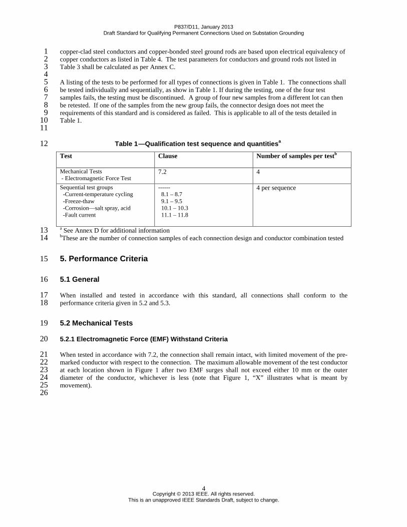
copper-clad steel conductors and copper-bonded steel ground rods are based upon electrical equivalency of 1 copper conductors as listed in Table 4. The test parameters for conductors and ground rods not listed in 2 Table 3 shall be calculated as per Annex C. 3 4 A listing of the tests to be performed for all types of connections is given in Table 1. The connections shall 5 be tested individually and sequentially, as show in Table 1. If during the testing, one of the four test 6 samples fails, the testing must be discontinued. A group of four new samples from a different lot can then 7 be retested. If one of the samples from the new group fails, the connector design does not meet the 8 requirements of this standard and is considered as failed. This is applicable to all of the tests detailed in 9 Table 1. 10 11
Table 1 —Qualification test sequence and quantitiesa 12 Test Clause Number of samples per testb
Mechanical Tests - Electromagnetic Force Test
7.2 4
Sequential test groups -Current-temperature cycling -Freeze-thaw -Corrosion—salt spray, acid -Fault current
a See Annex D for additional information 13 bThese are the number of connection samples of each connection design and conductor combination tested 14
5. Performance Criteria 15
5.1 General 16
When installed and tested in accordance with this standard, all connections shall conform to the 17 performance criteria given in 5.2 and 5.3. 18
5.2 Mechanical Tests 19
5.2.1 Electromagnetic Force (EMF) Withstand Criteria 20
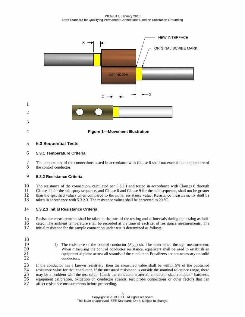
When tested in accordance with 7.2, the connection shall remain intact, with limited movement of the pre-21 marked conductor with respect to the connection. The maximum allowable movement of the test conductor 22 at each location shown in Figure 1 after two EMF surges shall not exceed either 10 mm or the outer 23 diameter of the conductor, whichever is less (note that Figure 1, “X” illustrates what is meant by 24 movement). 25 26
P837/D11, January 2013 Draft Standard for Qualifying Permanent Connections Used on Substation Grounding
This is an unapproved IEEE Standards Draft, subject to change.
5
1
2
3
Figure 1 —Movement Illustration 4
5.3 Sequential Tests 5
5.3.1 Temperature Criteria 6
The temperature of the connections tested in accordance with Clause 8 shall not exceed the temperature of 7 the control conductor. 8
5.3.2 Resistance Criteria 9
The resistance of the connection, calculated per 5.3.2.1 and tested in accordance with Clauses 8 through 10 Clause 11 for the salt spray sequence, and Clause 8 and Clause 9 for the acid sequence, shall not be greater 11 than the specified values when compared to the initial resistance value. Resistance measurements shall be 12 taken in accordance with 5.3.2.3. The resistance values shall be corrected to 20 °C. 13
5.3.2.1 Initial Resistance Criteria 14
Resistance measurements shall be taken at the start of the testing and at intervals during the testing as indi-15 cated. The ambient temperature shall be recorded at the time of each set of resistance measurements. The 16 initial resistance for the sample connection under test is determined as follows: 17
18 1) The resistance of the control conductor (RCC1) shall be determined through measurement. 19
When measuring the control conductor resistance, equalizers shall be used to establish an 20 equipotential plane across all strands of the conductor. Equalizers are not necessary on solid 21 conductors. 22
If the conductor has a known resistivity, then the measured value shall be within 5% of the published 23 resistance value for that conductor. If the measured resistance is outside the nominal tolerance range, there 24 may be a problem with the test setup. Check the conductor material, conductor size, conductor hardness, 25 equipment calibration, oxidation on conductor strands, test probe connections or other factors that can 26 affect resistance measurements before proceeding. 27
NEW INTERFACE
ORIGINAL SCRIBE MARK X
X
P837/D11, January 2013 Draft Standard for Qualifying Permanent Connections Used on Substation Grounding
This is an unapproved IEEE Standards Draft, subject to change.
6
The length of the control conductor (Lcc1) shall be taken between equalizers as shown in Figure 2. 1
2 Figure 2 —Control Conductor Resistance and Length 3
2) If the connection under test is joining two types of conductors, the non-control conductor 4 shall also be measured. Follow step 1) to determine LCC2 and RCC2 for the non-control 5 conductor. 6
3) Assemble the current cycle test loop as described in 8.6 shown in Figure 6 7 4) Measure the length (LSample1) from an equalizer to the center of the connection, as shown in 8
Figure 3. Then measure the length (LSample2) from the center of the connection to the 9 opposite equalizer. 10
5) Measure the total resistance (RTotal) across the entire connection sample from equalizer to 11 equalizer. See Figure 3. 12
6) All resistance measurements shall be temperature corrected to 20 °C (R20) before evaluating 13 the sample connection. Equation (1) shall be used to correct the resistance measurements. 14
Lcc1 (Rcc1)
P837/D11, January 2013 Draft Standard for Qualifying Permanent Connections Used on Substation Grounding
This is an unapproved IEEE Standards Draft, subject to change.
7
1 Figure 3 —Connection Assembly Length and Resistance 2
)]20(1[ 2020 −+=
c
m
TR
Rα
(1) 3
Where: 4
Rm is the measured resistance, Ω 5
R20 is the resistance corrected to 20°C, Ω 6 α20 is the temperature coefficient of resistance at 20(see Table C.1), 1/°C 7 Tc
is the temperature of the sample, °C 8
7) Using the corrected resistance values, determine the pass criteria of the initial sample 9 resistance using Equation (2). The pass criteria of the initial sample is that the initial 10 resistance of the test sample between equalizers shall not be greater than 1.1 times the 11 resistance on an equal length conductor. 12
10.1)]()[(
2
22
1
11≤
+CC
SampleCC
CC
SampleCC
Total
LLR
LLR
R (2) 13
RCC1
, RCC2
, LCC1
and LCC2
are as shown in Figure 2. If two types of conductor are not being used, 14
then RCC2
= RCC1
and LCC2
= LCC1
. 15
5.3.2.2 Final Resistance Criteria (after sequential tests) 16
Final resistance measurements for each sample (RFinal
) shall be measured as described in 5.3.2.3 and 17 depicted in Figure 3 for total resistance (R
Total), along with the ambient temperature as required in 5.3.2.4. 18
Final resistance measurements shall be corrected to 20 °C using Equation (1). Pass criteria for final 19
RTotal
LSample1
LCC1 LSample2 Lcc2
P837/D11, January 2013 Draft Standard for Qualifying Permanent Connections Used on Substation Grounding
This is an unapproved IEEE Standards Draft, subject to change.
8
resistance results shall be such that the corrected value of (RFinal
) does not exceed 1.5 times the initial (RTotal
) 1 value for each sample tested. 2
5.3.2.2.1 Criteria for Salt Spray Corrosion Test Sequences 3
A sample shall be considered as passing when the final resistance (RFinal
) does not exceed 1.5 times the 4 initial total resistance (R
Total) value. 5
5.3.2.2.2 Criteria for Acid Corrosion Test Sequences 6
A sample shall be considered as passing when the final resistance (RFinal
) does not exceed 1.5 times the 7 initial total resistance (R
Total) value. 8
9 Alternate pass criteria: A sample shall be considered as passing when the final resistance (R
Final) does not 10
exceed 1.5 times the total resistance (RTotal
) value of the control conductor which has been subjected to the 11 same acid test. The value for final resistance (R
Final) shall be calculated from equation (2) using values of 12
RCC1
, RCC2
, LCC1
and LCC2
taken from the control conductors, which were subjected to the same acid test as 13 the actual test samples. 14
5.3.2.3 Resistance Measurements 15
Resistance measurements shall be made when the conductor temperature is at ambient temperature. The 16 measurements shall be made across the control conductor and across each connection between potential 17 points located in the center of the equalizers adjacent to the connection or at the equivalent points on a solid 18 conductor. For these measurements, a current of a sufficiently low magnitude shall be used to avoid appre-19 ciable heating. 20
Resistance measurements shall be taken prior to each test within a sequential test group. For sequential test 21 samples, final resistance measurements shall be taken after the fault-current test in Clause 11. 22
5.3.2.4 Temperature Correction 23
Ambient temperature shall be recorded concurrently with each set of resistance measurements, and the 24 resistance shall be corrected to 20 °C. The corrected resistance shall be used in evaluating the performance 25 of the connection. 26
5.3.3 Fault-current Criteria 27
Connections tested in accordance with Clause 11 shall not melt, separate from, or move in relation to the 28 pre-marked conductor and must meet the resistance criteria set in 5.3.2.2. The conductor shall not fuse 29 within 50 mm of either end of a connection under test. 30
6. Test Procedures 31
6.1 General 32
Mechanical tests are to be conducted on new connections for electromagnetic withstand strength of the 33 connection in accordance with Clause 7. 34
P837/D11, January 2013 Draft Standard for Qualifying Permanent Connections Used on Substation Grounding
This is an unapproved IEEE Standards Draft, subject to change.
9
6.2 Mechanical Test Samples 1
The samples subjected to mechanical tests shall not be used for the sequential tests. 2
6.3 Sequential Test Samples 3
Current-temperature cycling, freeze-thaw, corrosion, and fault-current tests are to be conducted 4 sequentially. Use the same samples for all tests conducted in accordance with Clause 8 through Clause 11. 5
6.4 Connections Description 6
A description adequate for complete identification of the test connections shall be included in the test 7 report. 8
6.5 Test Conductors 9
The conductors shall conform to the latest of the following applicable standards: ASTM A363, ASTM 10 A510, ASTM B1, ASTM B2, ASTM B3, ASTM B8, ASTM B49, ASTM B105, ASTM B172, ASTM 11 B173, ASTM B174, ASTM B193, ASTM B227, ASTM B228, ASTM B229, ASTM B258, ASTM B416, 12 NEMA GR 1. 13
6.6 Test Assembly Methods 14
All assembly details not specifically defined in this standard shall be completely described in the test report. 15
6.7 Connection Preparation 16
Connections shall be prepared in accordance with the manufacturer’s recommendations for field 17 installation. 18
6.8 Installation 19
The method of installation and the installation tooling shall be in accordance with the manufacturer’s 20 recommendations for field installation. Unless otherwise specified in the manufacturer’s instructions, the 21 connections shall be installed so as to provide maximum stress on the connector (see Figure 4) during the 22 current-temperature cycling and fault-current tests. 23
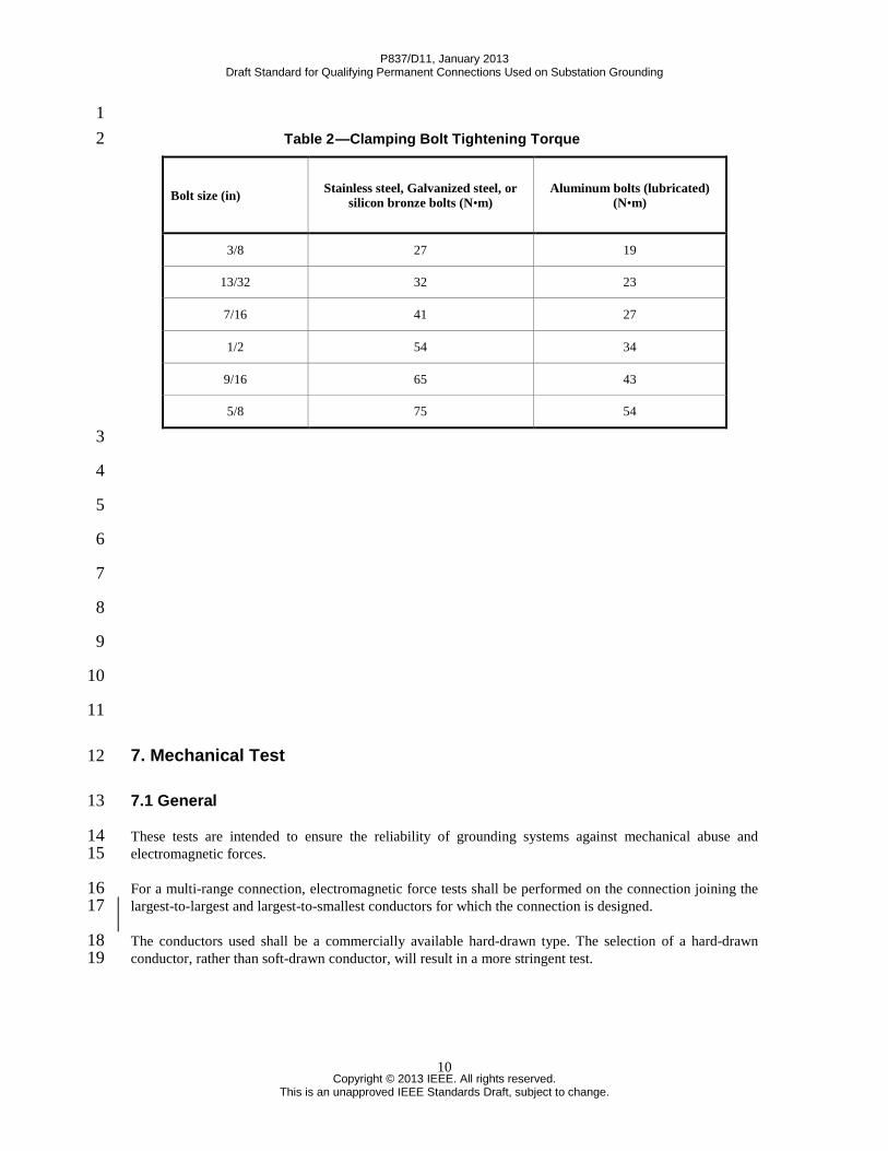
When clamping bolts are employed, they shall be tightened to the torque specified in Table 2, unless other-24 wise specified by the manufacturer. 25 26
P837/D11, January 2013 Draft Standard for Qualifying Permanent Connections Used on Substation Grounding
This is an unapproved IEEE Standards Draft, subject to change.
10
1 Table 2 —Clamping Bolt Tightening Torque 2
3
4
5
6
7
8
9
10
11
7. Mechanical Test 12
7.1 General 13
These tests are intended to ensure the reliability of grounding systems against mechanical abuse and 14 electromagnetic forces. 15
For a multi-range connection, electromagnetic force tests shall be performed on the connection joining the 16 largest-to-largest and largest-to-smallest conductors for which the connection is designed. 17
The conductors used shall be a commercially available hard-drawn type. The selection of a hard-drawn 18 conductor, rather than soft-drawn conductor, will result in a more stringent test. 19
This is an unapproved IEEE Standards Draft, subject to change.
11
7.2 Electromagnetic Force (EMF)Test 1
The EMF test will be conducted for connections used within the grid system, to join ground leads to the 2 grid system and for connections to rigid points used to join leads to equipment and structures. 3
7.2.1 EMF Test Samples 4
Four samples of each connection and conductor combination, as described in 7.1, shall be subjected to each 5 EMF test. Conductor sizes considered do not exceed 500 kcmil for a single connection and do not exceed 6 250 kcmil for a parallel (i.e. two conductors in lieu of a single conductor to achieve desired ampacity) 7 connection. Sizes below 2/0 are not to be considered except in the case of a variable connection per 7.1. 8 See Clause 4 for further information. 9
7.2.2 EMF Test Configuration 10
Each test sample consists of a minimum 1.22 m (48 inches) long section of exposed, non-secured 11 conductor. A test configuration may consist of a connection used within the grid system and connections 12 used to join ground leads to the grid system (Figure 4a) or a connection used to join the ground leads to 13 equipment and structures (Figure 4b). 14
Four Samples of the same design shall be tested. For both configurations, only one sample shall be tested at 15 a time to ensure accurate determination of conductor movement. 16
For Figure 4a test configurations, the bus connections (dead ends) must be electrically and mechanically 17 robust to prevent movement during the test. Figure 4b test configuration shall consist of one test sample 18 connector and a dead end bus connection. These test samples shall be connected to the rigid mounted 19 plates and/or bus extensions. In both configurations, connections shall be mounted in the same horizontal 20 plane. 21
P837/D11, January 2013 Draft Standard for Qualifying Permanent Connections Used on Substation Grounding
This is an unapproved IEEE Standards Draft, subject to change.
13
7.2.3 Electromagnetic Force Test Current 1
The magnitude of the test current for this test shall be an asymmetrical current defined as follows: 2
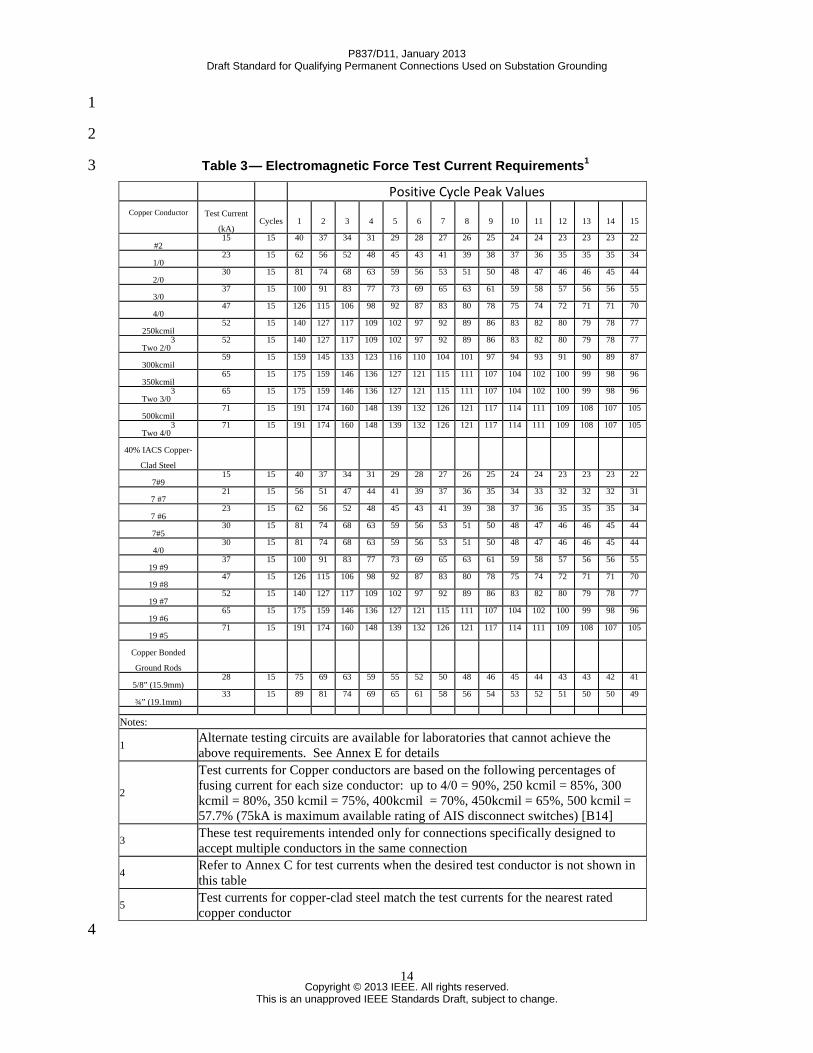
(1) The minimum RMS symmetrical test current that shall be applied is shown in Table 3, under column 3 ‘Rated Current (kA)’. See 7.2.3 (2) and 7.2.3 (3) for test current waveform and 7.2.4 for test duration. 4
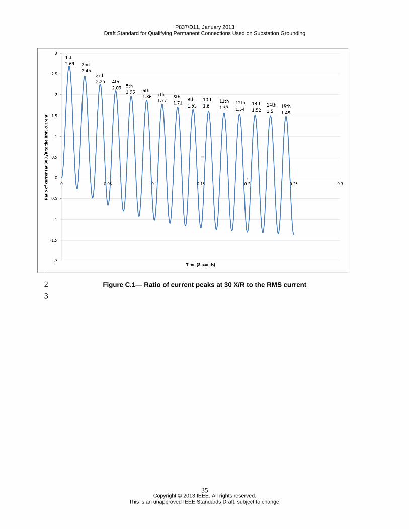
(2) Standard test current: The peak value for the first half cycle of the standard test current shall be 2.69 5 times the RMS test current indicated in 7.2.3 (1) above. Every subsequent positive peak is slightly lower 6 than the previous peak with a multiplier shown in Figure C.1. This is based on a system with an X/R ratio 7 of 30 and a maximum DC offset. See Table 3 below for the required magnitude of all positive cycle peaks. 8 All the positive waveform peaks must equal or exceed the target X/R Ratio=30 waveform peaks shown in 9 Table 3. An example waveform to be used in the standard test for 4/0 copper is shown in Figure 5. See 10 7.2.4 for duration of the test. 11
(3) Alternate test current: When it is physically not possible to generate a test current waveform in the 12 laboratory that matches with each peak accounting for a system X/R ratio=30, an alternate test current is 13 acceptable. The alternate test current requires meeting the first cycle peak indicated in Table 3. Each peak 14 of the alternate test current waveform is required to be equal or higher than the standard test current 15 waveform. The alternate test current waveform also is required to have a heating effect equal to that 16 generated by the standard test current. See 7.2.5 and Annex E for the duration of alternate test current. 17 However, there is no restriction of minimum value of X/R ratio for the alternate test. 18
19
20
21
22
23
24
25
26
27
28
29
30
31
32
P837/D11, January 2013 Draft Standard for Qualifying Permanent Connections Used on Substation Grounding
1 Alternate testing circuits are available for laboratories that cannot achieve the above requirements. See Annex E for details
2
Test currents for Copper conductors are based on the following percentages of fusing current for each size conductor: up to 4/0 = 90%, 250 kcmil = 85%, 300 kcmil = 80%, 350 kcmil = 75%, 400kcmil = 70%, 450kcmil = 65%, 500 kcmil = 57.7% (75kA is maximum available rating of AIS disconnect switches) [B14]
3 These test requirements intended only for connections specifically designed to accept multiple conductors in the same connection
4 Refer to Annex C for test currents when the desired test conductor is not shown in this table
5 Test currents for copper-clad steel match the test currents for the nearest rated copper conductor
4
P837/D11, January 2013 Draft Standard for Qualifying Permanent Connections Used on Substation Grounding
This is an unapproved IEEE Standards Draft, subject to change.
15
1
2 Figure 5 —Sample Wave Form for 4/0 Conductor 3
7.2.4 EMF Force Test Current Duration 4
The test current duration for the standard test current as indicated in 7.2.3(2) shall be minimum 15 cycles in 5 order to produce the electromagnetic force. Care should be taken to avoid a test duration significantly 6 longer than 15 cycles since the test currents are as much as 90% of the fusing current for a control 7 conductor. 8
The test current duration for the alternate test current as indicated in section 7.2.3(3) shall be such that the 9 equivalent heating effect in joules shall be the same as that generated by the standard test current 10 waveform. See Annex E for guidelines to calculate alternate test current duration. 11
7.2.5 EMF Test Number of Surges 12
The test shall consist of two surges. Repeat the surge after the conductor has been allowed to cool to 100 °C 13 or less. 14
7.2.6 Pass/Fail Criteria for EMF Test 15
The pass/fail criteria will be based on the movement of the conductor. The maximum allowable movement 16 of the test conductor after two EMF surges shall not exceed either 10 mm or the outer diameter of the 17 conductor, whichever is less. 18
-100
-50
0
50
100
150
0 0.05 0.1 0.15 0.2 0.25
Inst
anta
neou
s Cur
rent
(kA
)
Time (Seconds)
1st 126
3rd 106 4th
98 5th 92
6th 87
7th 83
8th 80
9th 78
10th 75
11th 74
12th 72
13th 71
14th 71
15th 70
2nd 115
P837/D11, January 2013 Draft Standard for Qualifying Permanent Connections Used on Substation Grounding
This is an unapproved IEEE Standards Draft, subject to change.
16
8. Current-temperature Cycling Test 1
8.1 General 2
This test is intended to ensure the conformance to resistance criteria of connections subjected to 3 temperature changes caused by fluctuating currents. 4
8.2 Current-temperature Cycling Test 5
This test shall be the first test conducted in a series of sequential tests, as listed in Table 1 (see Clause 4). 6
8.2.1 Conductor Combinations 7
When joining different types or sizes of conductors, the selection of the conductor combinations and test 8 current shall be that which results in the highest connection-temperature while producing the conductor 9 temperatures specified in Table 6. The following examples are provided to give some direction in 10 maximizing the temperature of the test loop while minimizing the thermal heat-sink properties of the loop 11 components. 12 Example 1: Connection for 19.1–25.4 mm copper-bonded steel rod to 6-2 AWG copper wire. From Table 13 6, test currents are 19.1 mm rod—570A, 25.4 mm rod—850 A, 6 AWG wire—230 A, 4 AWG wire—320 14 A, and 2 AWG wire—440 A. Select a 19.1 mm copper-bonded steel rod and 2 AWG copper wire and use 15 an initial test current of 440 A, which should achieve a 350 °C temperature on the 2 AWG wire. 16
Example 2: Connection for 12.7–15.9 mm stainless steel rod to 350–500 kcmil copper wire. From Table 6, 17 test currents are 12.7 mm rod—174 A, 15.9 mm rod—210 A, 350 kcmil wire, 1441 A, and 500 kcmil 18 wire— 1860 A. Select a 15.9 mm stainless steel rod and 350 kcmil copper wire and use an initial test 19 current of 210 A, which should achieve a 350 °C temperature on the stainless steel rod. 20
Example 3: Connection for 1/0–2/0 AWG copper wire to 4/0—250 kcmil copper wire. From Table 6, test 21 currents are 1/0 AWG wire—620 A, 2/0 AWG wire—725 A, 4/0 AWG wire—1010 A, and 250 kcmil 22 wire— 1140 A. Select a 2/0 and 4/0 AWG copper wire and use an initial test current of 725 A, which 23 should achieve a 350 °C temperature on the 2/0 AWG copper wire. 24
8.2.2 Test Samples 25
Four connections shall be required for each series of sequential tests. 26
8.2.3 Equalizer 27
Equalizers shall be installed on the stranded conductor on each side of each connection. The equalizer pro-28 vides an equipotential plane for resistance measurements and prevents the influence of one connection on 29 the other. For equalizer locations regarding connections used to join ground leads to the grid system refer to 30 Figure 3. For equalizer locations regarding connections used to join ground leads to equipment and 31 structures refer to Figure 4. Equalizers are not required on solid conductors. 32
Any form of equalizer that ensures contact of all strands of a conductor for the duration of the test may be 33 used. The equalizer used on control conductors shall be the same as those used in the test samples. 34
When the cables to be joined in a loop are identical, a continuous piece of cable may be used between the 35 connections. A short compression sleeve centered between the connections may then act as the equalizer. 36
NOTE—Resistance measurement points on solid conductors shall be the same as those used for conductors requiring 37 equalizers. 38
P837/D11, January 2013 Draft Standard for Qualifying Permanent Connections Used on Substation Grounding
This is an unapproved IEEE Standards Draft, subject to change.
17
8.2.4 Conductor Length 1
The exposed length of the conductor in the current cycle loop between the connection and the equalizers 2 shall be as given in Table 4. 3
Table 4 —Conductor Length From Connection to Equalizer 4 5
8.3 Ambient Conditions 6
The current-temperature cycling tests shall be conducted in a space free of drafts at an ambient temperature 7 of 10 °C to 40 °C. 8
8.4 Control Conductor 9
A control conductor, used for the purpose of obtaining conductor temperature, shall be installed in the cur-10 rent cycle loop between two equalizers. It shall be of the same type and size as the conductor of those 11 joined by the connection under test that established the highest temperature. Its length shall be the same as 12 the total of one test sample between equalizers as shown in Figure 2. 13
8.5 Current Cycling 14
8.5.1 Current Cycling Period 15
Each cycle of the current-temperature cycling test shall consist of maintaining the minimum temperature 16 specified in Table 6 on the control conductor for one hour and then cooling to room ambient. For suggested 17 test currents, refer to Table 5. 18
19 20
Copper wire or cable size
Steel or clad steel wire or rod
Exposed conductor length from connection to equalizer (+10%, –0.0%)
AWG or kcmil Diameter (mm) (mm)
Up to 2/0 Up to 11.1 300
Over 2/0 to 500 Over 11.1 to 19.1 600
Over 500 Over 19.1 900
P837/D11, January 2013 Draft Standard for Qualifying Permanent Connections Used on Substation Grounding
This is an unapproved IEEE Standards Draft, subject to change.
18
Table 5 —Applied Current Levels 1
Current Cycling Suggested Test Currents for Conductor Temperatures Specified in Table 6
Copper wire size AWG or kcmil Copper wire amperes
2 440
1/0 620
2/0 725
3/0 855
4/0 1010
250 1140
300 1295
350 1441
500 1860
40% conductivity copper-clad steel conductor size
40% conductivity copper-clad steel amperes
7/#9 315
7/#7 375
7/#6 440
7/#5 515
4/0 515
19/#9 520
19/#8 610
19/#7 700
19/#6 815
19/#5 940 Copper-bonded ground rod
nominal diametera Copper-clad steel rod
amperesb
5/8” (15.9mm) 425
3/4” (19.1mm) 570 2
a Actual rod diameter may vary from the nominal diameter (see NEMA GR 1) and could 3 require minor current adjustment during testing. 4 b Copper bonded steel rod based on 0.254 mm copper thickness 5
8.5.2 Current Cycling Number of Cycles 6
The connections shall be subjected to a minimum of 25 current cycles. 7
8.5.3 Current Cycling Test Temperature 8
The current shall be adjusted over the first five cycles to result in a steady-state temperature on the control 9 conductor specified in Table 6, and adjusted every five cycles thereafter as required to attain the specified 10
P837/D11, January 2013 Draft Standard for Qualifying Permanent Connections Used on Substation Grounding
This is an unapproved IEEE Standards Draft, subject to change.
19
steady-state temperature for a total of 25 cycles. 1
Table 6 —Conductor Temperature 2 3
4
5
6
7
8
9
10
8.6 Current Cycling Loop Configuration 11
The loop configuration shall provide a minimum space of 600 mm between the connected conductor, 750 12 mm from the floor, 1200 mm from the ceiling, and 600 mm from the walls. 13
A typical loop configuration is illustrated in Figures 6-10, but the loop may be bent back on itself in a “U” 14 or zigzag shape provided the above stated spacing is maintained. Figure 6 shall be used for wire-to-wire or 15 wire-to rod connections, while Figures 7-10 shall be used for wire–to-rigid point connections. 16
Conductor Temperature for current cycling test (°C)
Copper 350
Steel 350
Copper-bonded steel 350
Copper-clad steel 350
Galvanized steel 250
Stainless steel 350
Other Metals 250
P837/D11, January 2013 Draft Standard for Qualifying Permanent Connections Used on Substation Grounding
This is an unapproved IEEE Standards Draft, subject to change.
20
1 Figure 6 – Sequential test loop for cable-to-cable or cable-to-rod connections 2
3
8.7 Current Cycling Measurements 4
Temperature measurements for both the control conductor and the connectors shall be recorded at the 5 beginning of the test and after every five cycles. 6
P837/D11, January 2013 Draft Standard for Qualifying Permanent Connections Used on Substation Grounding
This is an unapproved IEEE Standards Draft, subject to change.
21
8.7.1 Current Cycling Temperature Measurement 1
Temperature measurements shall be recorded for the connections and the control conductor near the end of 2 the current heating period, with the current on. The temperature shall be measured by means of 3 thermocouples permanently installed on each connection as close as possible to the point on the current 4 path midway between the two conductors. One thermocouple shall be installed at the midpoint of the 5 control conductor. 6
8.7.2 Pass/Fail for Current Temperature Cycling Evaluation 7
The resistance measurements shall meet the requirements of section 5.3.2.2 8
9. Freeze-thaw Test 9
9.1 General 10
This test is intended to ensure the conformance to resistance criteria of the connections subjected to 11 repeated cycles of freezing and thawing in water. 12
9.2 Freeze-thaw Test 13
This test shall be the second test in a series of sequential tests as listed in Table 1. 14
9.3 Freeze-thaw Test Samples and Their Configuration 15
Test connections are the same test samples subjected to the current-temperature cycling test in accordance 16 with Clause 8. 17
The samples can be tested in a series loop or as individual test samples. 18
9.4 Freeze-Thaw Test Equipment 19
Containers resistant to freezing and heating temperatures and suitable for holding samples in a series loop 20 configuration or as individual samples shall contain enough water to submerge and cover the connection by 21 a minimum of 25.4 mm of water. 22
9.5 Freeze-thaw Test Cycle 23
9.5.1 Freeze-thaw Test Temperature 24
The freezing and thawing cycle shall consist of lowering the temperature of the test connection samples to 25 -10 °C or lower, and raising the temperature to at least 20 °C. The test samples shall remain at both the low 26 and high temperature for at least two hours during each cycle. 27
9.5.2 Freeze-thaw Number of Cycles 28
The connection shall be subjected to a minimum of 10 freeze-thaw cycles. 29
P837/D11, January 2013 Draft Standard for Qualifying Permanent Connections Used on Substation Grounding
This is an unapproved IEEE Standards Draft, subject to change.
22
9.5.3 Pass/Fail for Freeze-Thaw Test Evaluation 1
The resistance measurements shall meet the requirements of section 5.3.2.2 2
10. Corrosion Tests 3
10.1 General 4
The corrosion tests are designed to evaluate the corrosion resistance of connections. The acid and salt spray 5 test sequences are independent of each other. Both sequential tests shall be performed for connection 6 qualification to this standard. Plates required for cable-to-rigid connections (exothermic connections and 7 lugs) may be constructed from a corrosion-resistant material. A material such as “316 stainless steel” may 8 be used to avoid excessive corrosion of the plate. 9
10.2 Corrosion Test-Salt Spray 10
10.2.1 General 11
This test method covers the procedure for determining the corrosive effects of salt spray (sodium chloride) 12 on connections. 13
10.2.2 Salt Spray Corrosion Test 14
This test shall be the third test in a series of sequential tests, as shown in Table 1. 15
10.2.3 Salt Spray Test Samples 16
The test connection samples shall be the same connections tested in accordance with Clause 8 and Clause 17 9. 18
10.2.4 Salt Spray Test Applicable Standard 19
The test shall be performed according to ASTM B117-11 except Clause 5 and Clause 6 of the ASTM 20 standard shall be modified to accommodate conductor and connection design combinations being tested. 21
10.2.5 Salt Spray Test Duration 22
The test shall be conducted for a minimum of 500 hours. 23
10.2.6 Salt Spray Test Post-Corrosion Conditioning 24
After completion of the salt spray test, the test samples shall be rinsed in fresh water. Prior to taking resis-25 tance measurements, samples shall be heated for 1 hour at 100 °C to ensure dryness and then be returned to 26 ambient temperature. 27
10.2.7 Salt Spray Test Visual Evaluation 28
Connections and conductors shall be visually inspected for the type of corrosion, if any, and this 29 information shall be recorded in the test data, such as uniform corrosion, pitting, and galvanic action. 30
P837/D11, January 2013 Draft Standard for Qualifying Permanent Connections Used on Substation Grounding
This is an unapproved IEEE Standards Draft, subject to change.
23
10.2.8 Pass/Fail Salt Spray Test Evaluation 1
The resistance measurements shall meet the requirements of section 5.3.2.2 2
10.3 Corrosion test-acid (HNO3) 3
10.3.1 General 4
This test method covers the procedure for determining the corrosive effects of acid attack (nitric acid) on 5 connections. 6
10.3.2 Acid corrosion test 7
This test shall be the third test in a series of sequential tests, as shown in Table 1. 8
10.3.3 Acid test samples 9
The test connection samples shall be the same connections tested in accordance with Clause 8 and Clause 10 9. 11
10.3.4 Acid test submersion and samples 12
The test samples and conductor up to the equalizers shall be submerged in the acid solution. The equalizers 13 may or may not be included in the submerged section. This setup shall position the connection sample mid-14 way between exposed loop portions from the acid solution. 15
The control conductor shall be the same as used in Clause 8 and Clause 9, and the submerged portion shall 16 be equal in length to that of the submerged sample loop section. The beginning resistance of control 17 conductors shall be recorded for reference in accordance with 5.3.2. 18
If a connector is used where none of the conductors are copper or copper-clad steel a second control 19 conductor shall be made up. This control conductor will only be subjected to the acid test. It shall include 20 equalizers as in Figure 2 and utilize a copper conductor of the same diameter as the sample being tested. 21 This control will be used to determine the length of the acid test. 22
10.3.5 Acid test solution parameters 23
The acid solution shall be a 10% by volume concentration of nitric acid HNO3 and distilled water H2O. 24 See Annex B. 25
Solution volume shall be such as to provide a minimum ratio of 1 liter of 10% solution to 1.6 x104 mm2 of 26 submerged test sample surface area. The surface area includes the surface of all strands of the conductor 27 submerged in the solution. 28
The ambient temperature shall be 20 °C to 35 °C. 29
10.3.6 Acid test submersion time 30
Simple conductor loops (i.e., conductors of a single, uniform material such as copper) shall be submerged 31 in the acid solution for a time that will reduce the control conductor to 80% (minimum of 20% reduction) 32 of its original cross-sectional area. The reduction shall be determined by weight reduction per unit length or 33 increase in resistance of the control conductor. 34
P837/D11, January 2013 Draft Standard for Qualifying Permanent Connections Used on Substation Grounding
This is an unapproved IEEE Standards Draft, subject to change.
24
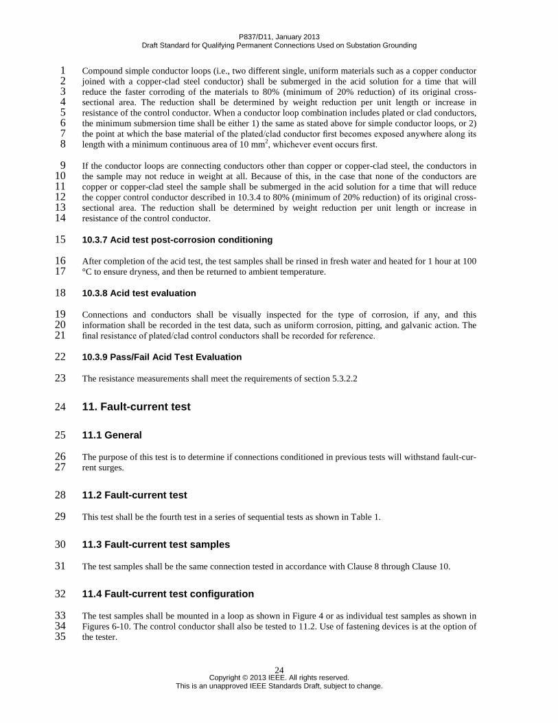
Compound simple conductor loops (i.e., two different single, uniform materials such as a copper conductor 1 joined with a copper-clad steel conductor) shall be submerged in the acid solution for a time that will 2 reduce the faster corroding of the materials to 80% (minimum of 20% reduction) of its original cross-3 sectional area. The reduction shall be determined by weight reduction per unit length or increase in 4 resistance of the control conductor. When a conductor loop combination includes plated or clad conductors, 5 the minimum submersion time shall be either 1) the same as stated above for simple conductor loops, or 2) 6 the point at which the base material of the plated/clad conductor first becomes exposed anywhere along its 7 length with a minimum continuous area of 10 mm2, whichever event occurs first. 8
If the conductor loops are connecting conductors other than copper or copper-clad steel, the conductors in 9 the sample may not reduce in weight at all. Because of this, in the case that none of the conductors are 10 copper or copper-clad steel the sample shall be submerged in the acid solution for a time that will reduce 11 the copper control conductor described in 10.3.4 to 80% (minimum of 20% reduction) of its original cross-12 sectional area. The reduction shall be determined by weight reduction per unit length or increase in 13 resistance of the control conductor. 14
10.3.7 Acid test post-corrosion conditioning 15
After completion of the acid test, the test samples shall be rinsed in fresh water and heated for 1 hour at 100 16 °C to ensure dryness, and then be returned to ambient temperature. 17
10.3.8 Acid test evaluation 18
Connections and conductors shall be visually inspected for the type of corrosion, if any, and this 19 information shall be recorded in the test data, such as uniform corrosion, pitting, and galvanic action. The 20 final resistance of plated/clad control conductors shall be recorded for reference. 21
10.3.9 Pass/Fail Acid Test Evaluation 22
The resistance measurements shall meet the requirements of section 5.3.2.2 23
11. Fault-current test 24
11.1 General 25
The purpose of this test is to determine if connections conditioned in previous tests will withstand fault-cur-26 rent surges. 27
11.2 Fault-current test 28
This test shall be the fourth test in a series of sequential tests as shown in Table 1. 29
11.3 Fault-current test samples 30
The test samples shall be the same connection tested in accordance with Clause 8 through Clause 10. 31
11.4 Fault-current test configuration 32
The test samples shall be mounted in a loop as shown in Figure 4 or as individual test samples as shown in 33 Figures 6-10. The control conductor shall also be tested to 11.2. Use of fastening devices is at the option of 34 the tester. 35
P837/D11, January 2013 Draft Standard for Qualifying Permanent Connections Used on Substation Grounding
This is an unapproved IEEE Standards Draft, subject to change.
25
11.5 Fault-current test duration 1
The fault duration shall be a minimum of 10 seconds. 2
11.6 Fault-current test current 3
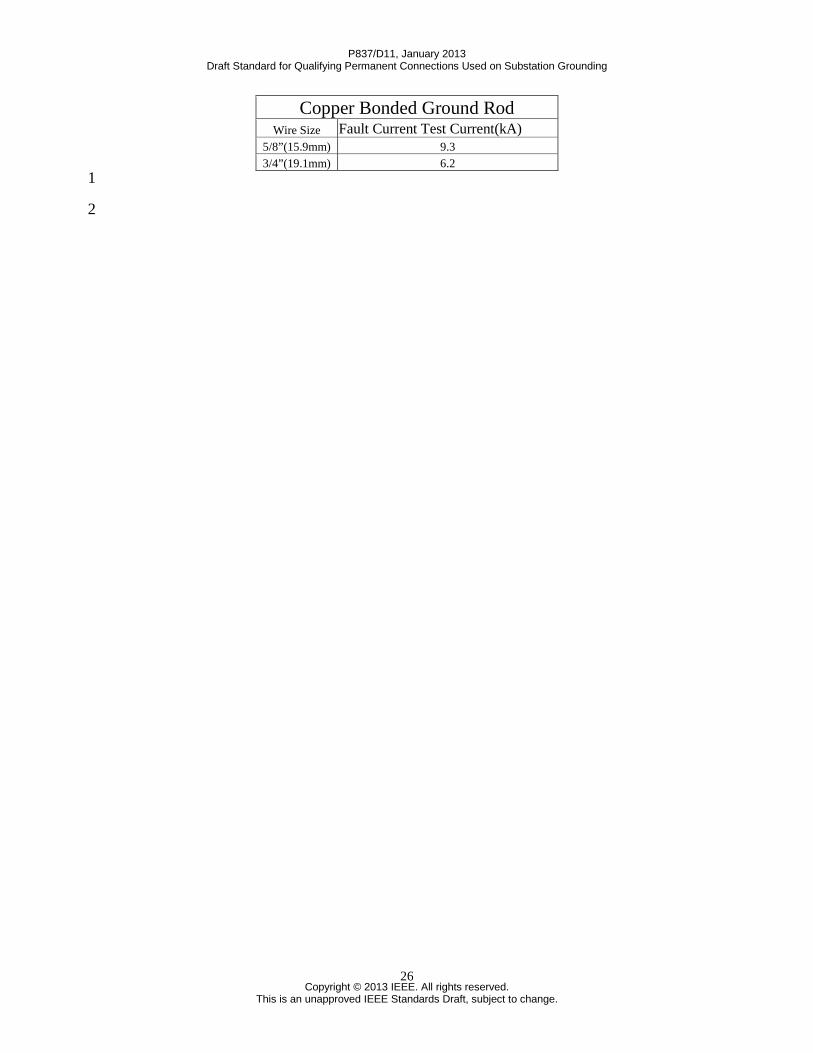
The symmetrical RMS fault current shall be 90% of the fusion current for the remaining cross-sectional 4 area of the control conductor calculated for a time of 10 second duration. Test currents for common 5 conductor sizes are listed in Table 7, for all other conductor sizes see Annex C. 6
NOTE—Ninety percent of the fusion current is established to prevent loss of the conductor and provide a 7 method of measuring resistance readings after three repeated fault surges. 8
Table 7 —Fault-current test current for selected conductors 9
Copper Conductor Cable size Fault Current Test Current (kA)
#2 2.7 1/0 4.3 2/0 5.4 3/0 6.8 4/0 8.6
250 kcmil 10.2 Two 2/0 10.8
300 kcmil 12.2 350 kcmil 14.2 Two 3/0 13.6
500 kcmil 20.3 Two 4/0 17.2
30% Copper-Clad Steel Conductor Cable size Fault Current Test Current (kA)
This is an unapproved IEEE Standards Draft, subject to change.
27
1
11.7 Fault-current number of surges 2
The test shall consist of three surges. Repeat each surge after the conductor has been allowed to cool to 100 3 °C or less. 4
NOTE—If the conductor fuses during the fault-current testing, and the connection under test has been 5 determined not to be the cause of the failure, the conductor may be spliced to complete the fault-current 6 testing. Only one such fusing along a given section between any two equalizers shall be allowed. The test 7 shot shall be redone for the full 10 seconds. 8
11.8 Fault-current test evaluation 9
The resistance measurements shall meet the requirements of section 5.3.2.2 10 11
P837/D11, January 2013 Draft Standard for Qualifying Permanent Connections Used on Substation Grounding
This is an unapproved IEEE Standards Draft, subject to change.
28
Annex A 1
(informative) 2
Bibliography 3
Bibliographical references are resources that provide additional or helpful material but do not need to be 4 understood or used to implement this standard. Reference to these resources is made for informational use 5 only. 6
[B1] ANSI/UL 467-1984, Safety Standard for Grounding and Bonding Equipment 7 [B2] ANSI/UL 486A-1982, Safety Standard for Wire Connectors and Soldering Lugs for Use with Copper 8 Conductors 9 [B4] IEEE 100™, The Authoritative Dictionary of IEEE Standards Terms, Seventh Edition 10 [B5] IEEE Std 80™-2000, IEEE Guide for Safety in AC Substation Grounding 11 [B6] Mixon, J., Corrosion Resistance Test for Copper and Copper Alloy Connector Products Used on 12 Grounding Grid Conductors and Electrodes. Harrisburg, PA: AMP, Inc., June 27, 1979 13 [B7] Mixon, J., Exploratory Acid Corrosion Tests. Harrisburg, PA: AMP, Inc., Oct. 5, 1978 14 [B8] NACE TM0169-95, Laboratory Corrosion Testing of Metals for the Process Industries 15 [B9] NEMA CC1-1993, Electrical Power Connectors for Substations 16 [B10] NEMA CC3-1973 (R 1983), Connectors for Use Between Aluminum or Aluminum/Copper 17 Overhead Conductors 18 [B11] Sverak, J. G., “Safe substation grounding, Part II,” IEEE Transactions on Power Apparatus and Sys 19 tems, vol. PAS-101, pp. 4006–4023, Oct. 1982 (IEEE Paper 82 WM 180-8) 20 [B12] Sverak, J. G., “Sizing of ground conductors against fusing,” IEEE Transactions on Power Apparatus 21 and Systems, vol. PAS-100, pp. 51–59, Jan. 1981 (IEEE Paper F80 256-8) 22 [B13] VDE Standard 0142.64, Regulation for Earthings in AC Installation with Rated Voltages Above 1 23 kV (Germany). 24 [B14] Reichman, J. Vainberg, M., and Kuffel, J., “Short-circuit capacity of temporary grounding cables,” 25 IEEE Transactions on Power Delivery, vol. 4, no. 1, pp. 260-271, Jan 1989. 26 27
P837/D11, January 2013 Draft Standard for Qualifying Permanent Connections Used on Substation Grounding
This is an unapproved IEEE Standards Draft, subject to change.
30
Annex C 1 2 (normative) 3 4 Conductive Ampacity Calculaton (see IEEE 80-2000 [B5] and Sverak, J.G. [B12]) 5
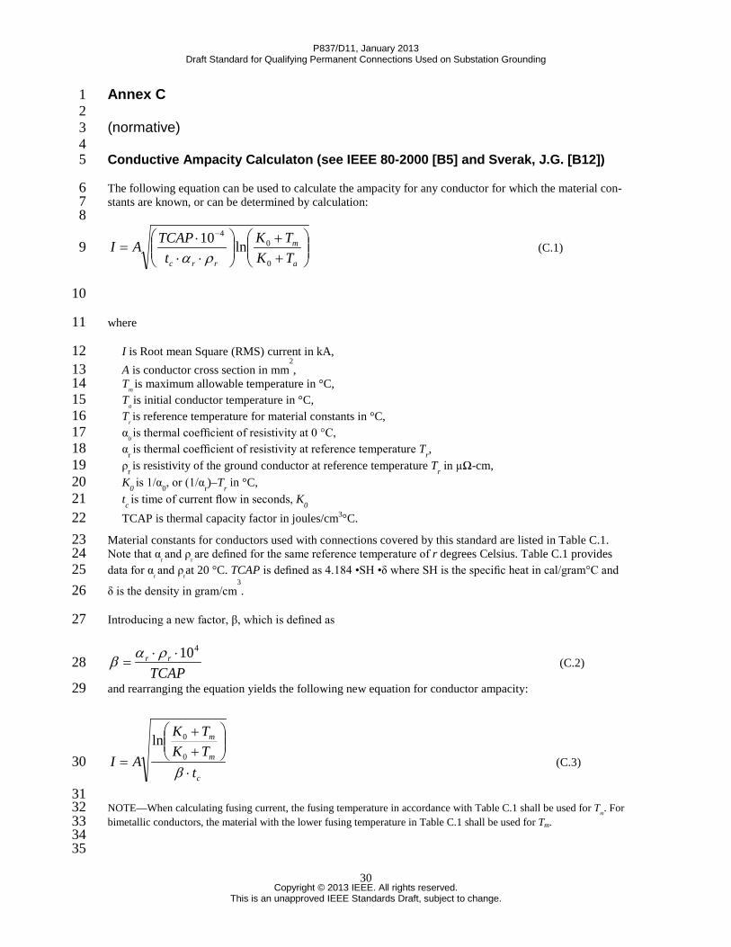
The following equation can be used to calculate the ampacity for any conductor for which the material con-6 stants are known, or can be determined by calculation: 7 8
++
⋅⋅⋅
=−
a
m
rrc TKTK
tTCAPAI
0
04
ln10ρα
(C.1) 9
10
where 11
I is Root mean Square (RMS) current in kA, 12 A is conductor cross section in mm
2, 13
Tm is maximum allowable temperature in °C, 14
Ta is initial conductor temperature in °C, 15
Tr is reference temperature for material constants in °C, 16
α0 is thermal coefficient of resistivity at 0 °C, 17
αr is thermal coefficient of resistivity at reference temperature Tr, 18 ρr is resistivity of the ground conductor at reference temperature Tr in µΩ-cm, 19 K0 is 1/α0, or (1/αr)–Tr in °C, 20 tc is time of current flow in seconds, K0 21 TCAP is thermal capacity factor in joules/cm3°C. 22
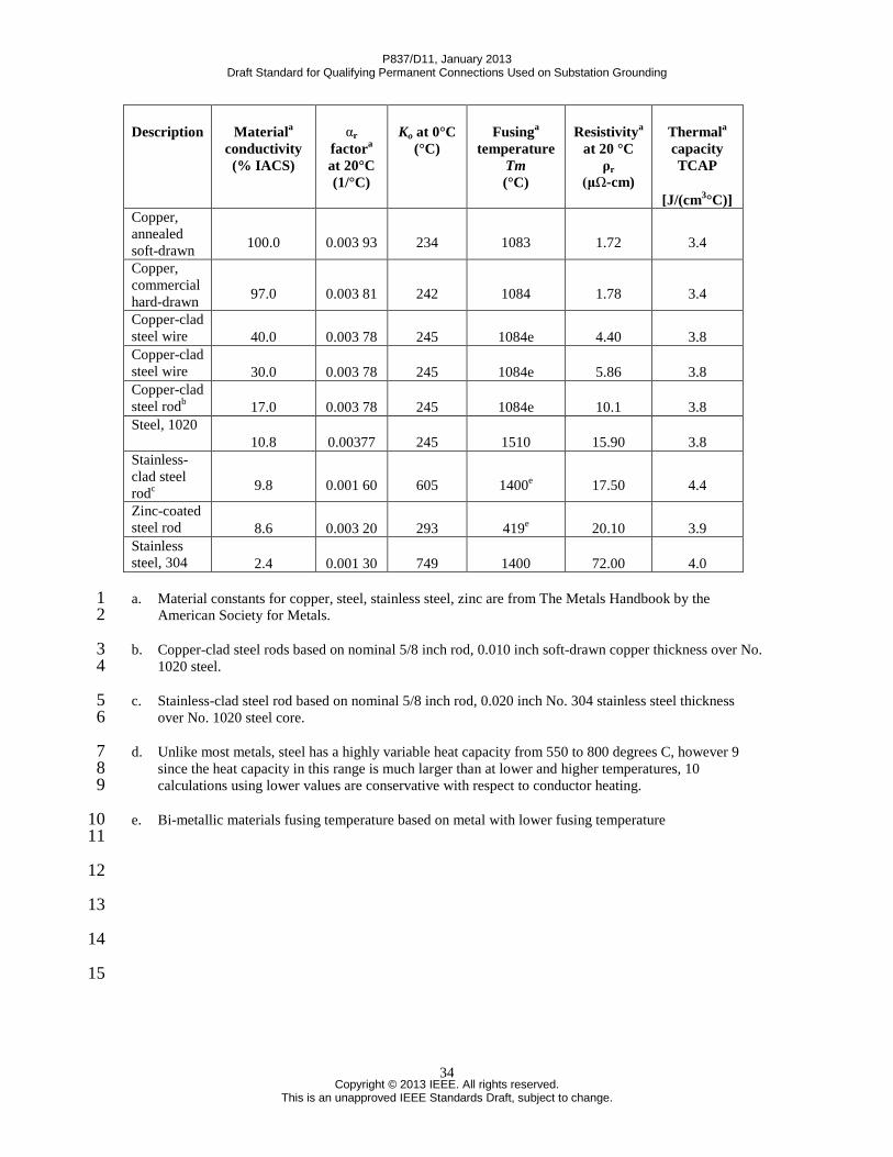
Material constants for conductors used with connections covered by this standard are listed in Table C.1. 23 Note that α
r and ρ
r are defined for the same reference temperature of r degrees Celsius. Table C.1 provides 24
data for αr and ρ
rat 20 °C. TCAP is defined as 4.184 •SH •δ where SH is the specific heat in cal/gram°C and 25
δ is the density in gram/cm3. 26
Introducing a new factor, β, which is defined as 27
TCAPrr
410⋅⋅=
ραβ (C.2) 28
and rearranging the equation yields the following new equation for conductor ampacity: 29
c
m
m
tTKTK
AI⋅
++
=β
0
0ln (C.3) 30
31 NOTE—When calculating fusing current, the fusing temperature in accordance with Table C.1 shall be used for Tm. For 32 bimetallic conductors, the material with the lower fusing temperature in Table C.1 shall be used for Tm. 33 34 35
P837/D11, January 2013 Draft Standard for Qualifying Permanent Connections Used on Substation Grounding
This is an unapproved IEEE Standards Draft, subject to change.
31
The value given by the above equations is for a symmetrical waveform. To use them on a waveform with a 1 high X/R ratio the decrement factor must be used. The decrement factor is used to determine the RMS 2 current of an asymmetrical waveform which has the same energy as a symmetrical wave: 3 4 IF=If•Df (C.4) 5 6 Where 7
IF is the effective RMS value of approximate asymmetrical current for the entire duration of a fault in A 8 If is the RMS current of the asymmetrical wave after the transient has decayed away 9 Df is the decrement factor 10
11 The decrement factor can be calculated from the equation: 12 13
)1(12
a
f
Tt
f
af e
tTD
−
−+= (C.5) 14
15 Where 16
tf is the time of the fault 17 Ta is the DC offset time constant in s [Ta =X/ωR, for 60 Hz, Ta=X/120πR] 18
19 Once the asymmetrical current which will fuse a conductor has been determined the magnitude of each 20 current peak of this waveform can be calculated. For an X/R ratio of 30 the ratio of the first fifteen peaks to 21 the RMS current is given in Figure C1. 22 23 Example 1: Electromagnetic force test current calculation 24
Solving for the minimum electromagnetic-force test current (Itest
), and the peak currents (Ipeak
) of 100% 25 conductivity 350 kcmil copper conductor. This test current duration is 15 cycles (0.25 seconds): 26
27
28
kAI symfu 68.9925.0*8.1940234
1084234ln177sin =
++
= RMS symmetrical 29
30 To find the current of an asymmetrical waveform which has the same energy as this symmetrical current 31 the decrement factor must be calculated or found in Table 10 of IEEE STD 80-2000. For the X/R ratio of 32 30 this is: 33
Let
A = 177 mm2 Tm = 1084 °C Ta = 40 °C K0 = 234 °C β = 19.8 tc = 0.25 s
P837/D11, January 2013 Draft Standard for Qualifying Permanent Connections Used on Substation Grounding
This is an unapproved IEEE Standards Draft, subject to change.
32
148.1125.0
12030
1 12030
25.0*2
=
−
+=
−
ππ eD f 1
Using the decrement factor to find the asymmetrical current gives: 2
kAkAD
III
f
symgfutestasymgfu 83.86
148.168.99sin
sin ==== 3
Ifusing asym is the amount of asymmetrical current at an X/R of 30 which would fuse the copper in 15 cycles 4 (0.25 seconds). 5
To determine what current a connector should be tested at, the percentage of fusing current to be used with 6 that particular size of conductor must be known. From Table 3, The asymmetrical test current is based on 7 the following percentages of fusing current, Ifusing asym, for each size conductor: any conductor up to 4/0 = 8 90%, any conductor larger than 4/0 up to and including 250kcmil = 85%, any conductor larger than 9 250kcmil up to and including 300kcmil = 80%, any conductor larger than 300kcmil up to and including 10 350kcmil = 75%, any conductor larger than 350kcmil up to and including 400kcmil = 70%, any conductor 11 larger than 400kcmil and smaller than 500kcmil = 65%, all conductors 500kcmil or larger = 57.7%. To 12 determine the current to be used in a particular test the appropriate percentage of fusing current should be 13 divided by 100 then multiplied by the asymmetrical current. For 350kcmil conductor this is equal to: 14
kAxII asymgfuasymtest 6583.8675.010075
sin === (Rounded to nearest kA) 15
To determine the required peak current value for each cycle another scaling factor required is the ratio of 16 the current peak to the RMS value; these values are given in Figure C1. Each of the fifteen peaks can be 17 calculated by multiplying the asymmetrical current by this scaling factor. 18
This is an unapproved IEEE Standards Draft, subject to change.
33
The test current shall meet or exceed this current value for each of the fifteen peaks. In the event of a 1 conflict between the value produced by this calculation method and Table 3, the value in Table 3 shall be 2 used. This calculation method is only intended for use with conductors not included in Table 3. 3
Example 2: Calculation of current for fault current test 4
Solving for the minimum fault current test current (Itest
) of 100% conductivity copper, 350 kcmil conductor. 5 The duration of this test current is 10 seconds with a magnitude equal to 90% of the fault capable of fusing 6 the conductor in 10 seconds. The decrement factor can be neglected because of the length of the fault: 7
8
lsymmetricaRMSkAx
I symgfu 76.15108.19
402341084234ln
177sin =
++
= 9
The test current is 90% of this fusing current: 10
AkAkAxxII symgfutest 1901419.1476.159.09.0 sin ==== 11
The RMS value of the current for the fault-current test shall meet or exceed this value when measured over 12 the entire ten seconds of the test. In the event of a conflict between the value produced by this calculation 13 method and Table 7, the value in Table 7 shall be used. This calculation method is only intended for use 14 with conductors not included in Table 7. 15
16
Let
A = 177 mm2 Tm = 1084 °C Ta = 40 °C K0 = 234 °C β = 19.8 tc = 10 s
P837/D11, January 2013 Draft Standard for Qualifying Permanent Connections Used on Substation Grounding
a. Material constants for copper, steel, stainless steel, zinc are from The Metals Handbook by the 1 American Society for Metals. 2
b. Copper-clad steel rods based on nominal 5/8 inch rod, 0.010 inch soft-drawn copper thickness over No. 3 1020 steel. 4
c. Stainless-clad steel rod based on nominal 5/8 inch rod, 0.020 inch No. 304 stainless steel thickness 5 over No. 1020 steel core. 6
d. Unlike most metals, steel has a highly variable heat capacity from 550 to 800 degrees C, however 9 7 since the heat capacity in this range is much larger than at lower and higher temperatures, 10 8 calculations using lower values are conservative with respect to conductor heating. 9
e. Bi-metallic materials fusing temperature based on metal with lower fusing temperature 10 11
12
13
14
15
P837/D11, January 2013 Draft Standard for Qualifying Permanent Connections Used on Substation Grounding
This is an unapproved IEEE Standards Draft, subject to change.
36
Annex D 1
(informative) 2
Test Sequencing 3
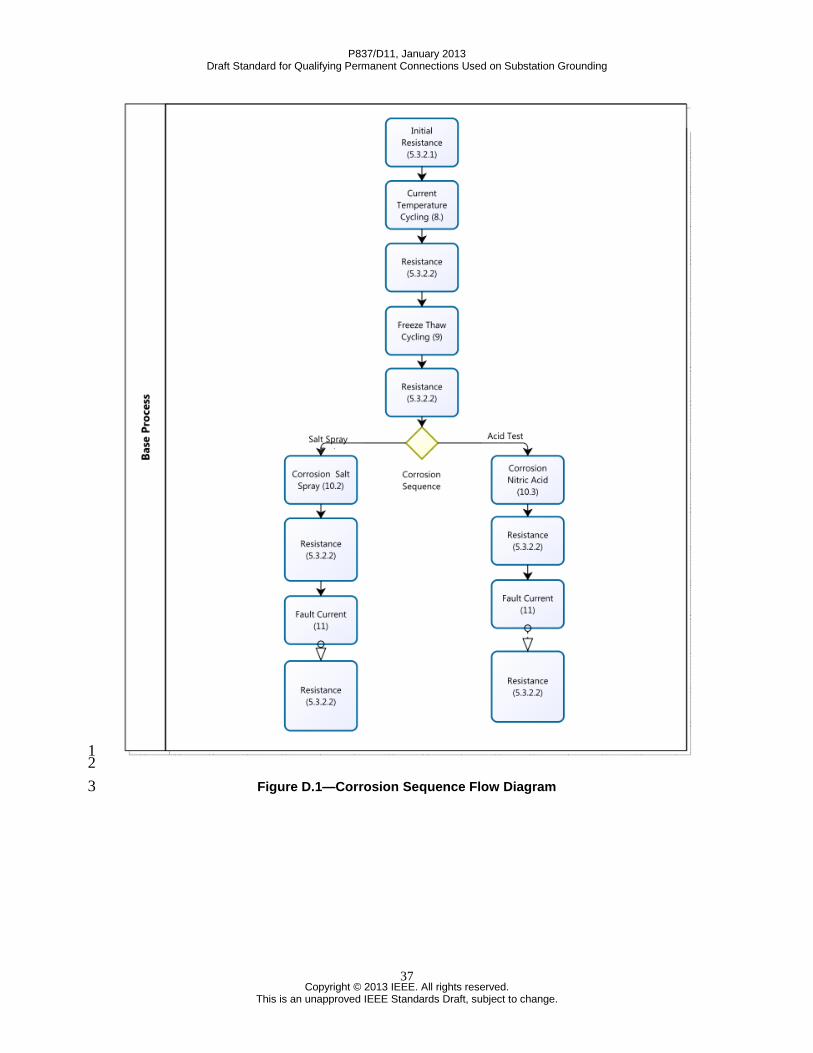
Table 1 identifies all testing and samples required for qualifying connections per this standard. Figure D.1 4 and Figure D.2 will assist in identifying each test and measurement/evaluation point throughout the multi-5 step test programs. 6
7 8
P837/D11, January 2013 Draft Standard for Qualifying Permanent Connections Used on Substation Grounding
This is an unapproved IEEE Standards Draft, subject to change.
39
Annex E 1 2 (informative) 3 4 Effects Of Asymmetrical Currents and Multiple Conductor Test 5 Requirements 6
E.1 Asymmetrical Currents 7
The test current requirements of this standard are based on a test current with a system X/R ratio of 30. 8 This relatively high X/R ratio was chosen to include the effects of the very high asymmetrical peak current 9 magnitudes of the first few cycles typically present at large transmission substation and generating plants 10 with high available short circuit currents, and is consistent with the test requirements in the 2009 revision 11 of ASTM F855 for temporary protective grounds. These high current peaks create corresponding high 12 electromagnetic forces that can fail the connection, conductor or both during a fault, even if the fault is 13 cleared well before the thermal limit of the conductor and connection. Asymmetrical current is defined by 14 the following equation: 15
𝑖 = 𝑉𝑚𝑍 𝑠𝑖𝑛(𝜔𝑡 + 𝛼 − 𝜃) − 𝑒
−𝑅𝑡𝐿 𝑠𝑖𝑛(𝛼 − 𝜗)=|𝐼| sin(𝜔𝑡 + 𝛼 − 𝜗) − 𝑒
−𝜔𝑅𝑡𝑋 𝑠𝑖𝑛(𝛼 − 𝜃) 16
where: 17 18
|Vm| = peak voltage available, V, |Z| = circuit impedance, Ω , |I| = peak current available, A, R = circuit resistance, Ω, t = time from current initiation, ω = 2πf (radians/s), f = frequency, Hz, α = voltage angle at current initiation, radians, θ = circuit phase angle, radians, and L = circuit inductance X/ω, H. X = inductive reactance, XL, Ω.
19 The maximum instantaneous peak occurs very nearly when t = 0 and the combination of (α - θ) = π/2. The 20 equation is comprised of an AC and DC portion. The sine function represents the symmetrical AC portion. 21 The exponential function represents the decaying DC portion. The summation of the AC and DC portions 22 yields the asymmetrical wave. It should be noted that the exponential decay of the transient portion is 23 slowed as the X/R increases. See Figure E.1, which represents a 47 kA current with an X/R of 30 and a 721 24 joule heating. 25
26
P837/D11, January 2013 Draft Standard for Qualifying Permanent Connections Used on Substation Grounding
This is an unapproved IEEE Standards Draft, subject to change.
40
1 2 3
Figure E.1— 4 5
For circuits with an X/R=30, the asymmetrical test current peaks for each cycle are listed in Table 3. These 6 test values represent the peak values of each cycle of the waveform in a 15 cycle test. Note that Fig. E.1 7 shows the waveform does not fully decay to full symmetry in 15 cycles for this X/R; therefore, the RMS 8 value of the last cycle is higher than the overall RMS symmetrical current rating of the conductor. 9
E.2 Alternate test current 10
11 If the test laboratory is unable to achieve the required waveform of Table 3, along with the 15 cycle 12 duration, an alternate test may be performed by increasing the equivalent RMS test current, varying the 13 X/R ratio, or a combination of both. The resulting test circuit must still achieve the first (1st) maximum 14 peak current and each successive cycle peak must meet or exceed the peak of the required wave form of 15 Table 3. However, to prevent exceeding the thermal rating of the cable, the test duration must be reduced. 16 In any alternate test circuit, the total I2t of the alternate test current waveform must meet or exceed that of 17 the required waveform of Table 3. 18
Two examples of alternate test waveforms are shown in Figure E.2 – one alternate test current based on an 19 X/R ratio of 20 and the other alternate test current based on an X/R ratio of 0 (symmetrical current). 20
21 22
-100
-50
0
50
100
150
-0.05 0.05 0.15 0.25
Cur
rent
(kA)
Time (seconds)
i(t)
P837/D11, January 2013 Draft Standard for Qualifying Permanent Connections Used on Substation Grounding
This is an unapproved IEEE Standards Draft, subject to change.
41
1 Figure E.2— 2
3
E.3 Testing for multiple cables and individual connections 4
5 Clause 7 includes test requirements for single cables in single connections, as well as a limited number of 6 two cables terminated in connections specifically designed for multiple cables. In locations with extremely 7 high short circuit current, or in upgrading of existing grounding systems, multiple ground risers might be 8 required between the ground grid and the equipment or structures. This creates two difficulties in this test 9 standard: (1) there are numerous variables when using two single-cable connections at a structure or 10 equipment that make it impossible to create one test configuration that represents all possible applications, 11 and (2) the theoretical high thermal current capability of multiple conductors (even after derating for 12 unequal current division) might exceed the current capabilities of the existing test laboratories (as well as 13 the available short circuit current on even the strongest system. When using multiple ground risers instead 14 of larger single conductors, the user should be aware of the following. 15
1. Unless the current paths have identical impedance, it should not be assumed that the fault current will 16 divide equally. The ultimate thermal rating of each conductor should be reduced by at least 10% to account 17 for unequal current division. This guideline is applicable when the conductors are placed closely side by 18 side. As the spacing between the conductors increases, the current sharing becomes more unequal. 19
2. The close proximity of the parallel conductors creates electromagnetic forces that tend to pull the two 20 conductors together. This is true for both low and high asymmetrical currents. High asymmetrical fault 21 currents can create extreme electromechanical forces between the conductors, which can easily break the 22 connection. 23
24
P837/D11, January 2013 Draft Standard for Qualifying Permanent Connections Used on Substation Grounding
This is an unapproved IEEE Standards Draft, subject to change.
42
Users applying multiple single-conductor connections in lieu of a larger single conductor should perform 1 their own tests to determine the ratings for the application. Guidance for when such tests are performed is 2 given below. These guidelines are based on a limited number of tests and are not intended to address all 3 concerns. 4
Select the test current from Table 3 for the equivalent sized, taking into consideration any derating for 5 unequal current division or other safety factors. For example, using two 4/0 conductors instead of a single 6 500kcmil conductor, or two 2/0 conductors. 7
Test duration: 15 cycles (0.25 seconds). 8
Install the multiple single-conductor connections in the test configuration, duplicating as close as possible 9 the separation distance and orientation of the conductors and connections to each other as they will be 10 installed in the field application. Note that the electromechanical forces between the individual conductors 11 reduce as the spacing between them is increased. The inequality in current division also increases with the 12 increase in the spacing between the conductors. Note also that the orientation of the connections relative to 13 each other and to the structure or equipment to which they are applied can have a significant effect on the 14 results. 15