53
PA/4600 PA/4600 PRINTER - APPLICATOR PRINTER - APPLICATOR PA/6000 PA/6000 4600-010 Revision G
PA/4600PA/4600PRINTER - APPLICATORPRINTER - APPLICATOR
PA/6000PA/6000
4600-010Revision G
Diagraph - an ITW Company PA/4600 & PA/6000 User Manual
Diagraph, an ITW company, continually improves its products, and reserves the right to change or discon-tinue specifications and designs shown in this manual without notice and without incurring obligation. Diagraph has made every effort to verify the informa-tion contained in this manual, but reserves the right to correct any error at the time of the manual’s next revision.© 2008 Illinois Tool Works Inc. All rights reserved.Printed in the United States of America
Page 1
Diagraph - an ITW Company PA/4600 & PA/6000 User ManualIntroduction
1.0 Introduction
1.1 The PA/4600 and PA/6000 Printer - Applicators
The PA/4600 and PA/6000 are sixth generation, next label out, print and apply systems designed for modularity, continuous labeling, self-diagnostics, and ease of use. Modularity of design provides the basis for ease of installation, setup, and maintenance. The electronics system employs a hardware-specific design, thus increasing reliability and throughput. The hardware was developed to simplify construction, and increase longevity by using durable materials. This unit will perform 24/7 operation in harsh environments and operate trouble-free, given that the appropriate preventative maintenance is performed on regular service intervals.
1.2 Product Safety
Safety awareness is critical when working with equipment that contains moving parts and extending pneumatic cylinders. Please read all warnings and cautions thoroughly before operating this device.
This product meets the requirements of CAN/CSA-22.2 NO.60950-00 * UL 60950 using Diagraph an ITW Company approved items. Units are only tested and qualified with Diagraph an ITW Company approved parts and accessories. Use of other parts or accessories may introduce potential risks that Diagraph an ITW Company can assume no liability for.
WARNINGS
• WARNING - Moving parts of this machine can present hazards. Components that cannot be guarded because of loss of functionality are marked with a warning symbol.
• Be aware of the tamp cylinder extension distance, and avoid accidental trig-gering of the photosensor.
• When servicing the unit’s electronic assemblies, always remove the power cord from the unit to prevent accidental shock.
• When running for extended periods of time, use caution when accessing the drive module circuitry. The motor drive power transistors, motor case, and motor heatsink can become hot under constant use.
• Always close the air inlet valve shutoff when removing or servicing pneu-matic module or tamp cylinder.
• Wear personal protective equipment, as instructed by your supervisor, when operating or working near this device.
COMPLIANCE
• CAUTION: Not for use in a computer room as defined in the Standard for the Protection of Electronic Computer/ Data Processing Equipment, ANSI/NFPA 75.
Introduction Page 2
Diagraph - an ITW Company PA/4600 & PA/6000 User ManualIntroduction
• ATTENTION: Ne peut être utilissé dans une salle d’ordinateurs telle que définie dans las norme. ANSI/NFPA 75 Standard for the Protection of Elec-tronic Computer/ Data Processing Equipment
• This unit has been tested and found to comply with the limits for a Class A device, pursuant to part 15 of the FCC Rules.
• This unit has been tested to comply with CE Standards.
• This unit is equipped with an Emergency Stop switch. Depressing this switchwill cause all machine operations to cease.
• This unit was tested and it was determined that a potential for tipping exists in certain orientations. In compliance with UL safety standards, the stand must be secured to the surface where it is located. Additionally, this type of securing will result in greater product application accuracy.
1.3 Document Conventions
Formatting conventions are used throughout this manual as a method of providing consistency for notes and warnings.
Goal: This indicates a particular objective for the section.
Note: This indicates that there is more information available for the in-depth reader..
1.4 Warranty Information
The PA/4600 and PA/6000 systems, including all components unless otherwise specified, carry a limited warranty.
For all warranty terms and conditions, contact Diagraph, an ITW Company, for a complete copy of the Limited Warranty Statement.
WARNING This symbol indicates a danger of injury to the user. Hazards are identified by the exclamation mark in a triangle and bold italics text.
Introduction Page 3
Diagraph - an ITW Company PA/4600 & PA/6000 User ManualIntroduction
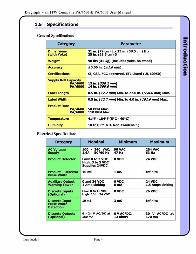
1.5 Specifications
General Specifications
Category Parameter
Dimensions(with Yoke)
31 in. (79 cm) L x 23 in. (58.5 cm) H x 25 in. (63.5 cm) D
Weight 90 lbs (41 kg) (includes yoke, no stand)
Accuracy ±0.06 in. (±1.6 mm)
Certifications Œ, CSA, FCC approved, ETL Listed (UL 60950)
Supply Roll CapacityPA/4600PA/6000
13 in. (330.2 mm)14 in. (355.6 mm)
Label Length 0.5 in. (12.7 mm) Min. to 22.0 in. (558.8 mm) Max.
Label Width 0.5 in. (12.7 mm) Min. to 4.0 in. (101.6 mm) Max.
Product RatePA/4600PA/6000
50 PPM Max.110 PPM Max.
Temperature 41°F - 104°F (5°C - 40°C)
Humidity 10 to 85% RH, Non-Condensing
Electrical Specifications
Category Nominal Minimum Maximum
AC VoltageSupply
100 - 240 VAC, 1.6A 50/60 Hz
90 VAC47 Hz
264 VAC63 Hz
Product Detector Low: 0 to 3 VDCHigh: 3 to 5 VDCSupplies 24VDC
0 VDC 24 VDC
Product Detector Pulse Width
10 mS 1 mS Infinite
Auxiliary OutputWarning Tower
0 and 24 VDC1 Amp sinking
0 VDC0 mA
24 VDC1.5 Amps sinking
Discrete Inputs(Optional)
Low: 0 to 10 VDCHigh: 10 to 24 VDC
0 VDC 26 VDC
Discrete Input Pulse Width Detection
10 mS 3 mS Infinite
Discrete Outputs(Optional)
0 - 24 V AC/DC at 150 mA
0 V AC/DC, 13 ohms
30 V AC/DC at 170 mA
Introduction Page 4
Diagraph - an ITW Company PA/4600 & PA/6000 User ManualIntroduction
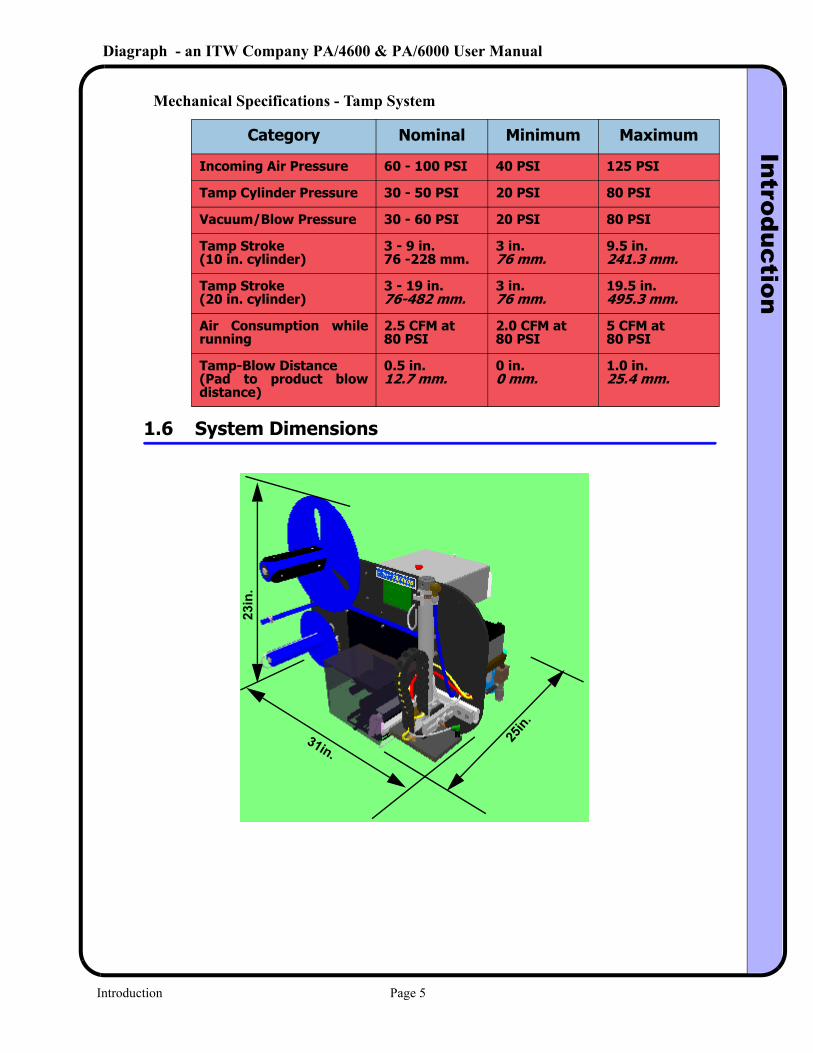
Mechanical Specifications - Tamp System
Category Nominal Minimum Maximum
Incoming Air Pressure 60 - 100 PSI 40 PSI 125 PSI
Tamp Cylinder Pressure 30 - 50 PSI 20 PSI 80 PSI
Vacuum/Blow Pressure 30 - 60 PSI 20 PSI 80 PSI
Tamp Stroke(10 in. cylinder)
3 - 9 in.76 -228 mm.
3 in.76 mm.
9.5 in.241.3 mm.
Tamp Stroke(20 in. cylinder)
3 - 19 in.76-482 mm.
3 in.76 mm.
19.5 in.495.3 mm.
Air Consumption while running
2.5 CFM at 80 PSI
2.0 CFM at 80 PSI
5 CFM at 80 PSI
Tamp-Blow Distance(Pad to product blow distance)
0.5 in.12.7 mm.
0 in.0 mm.
1.0 in.25.4 mm.
1.6 System Dimensions
31in.
23in
.
25in.
Introduction Page 5
Diagraph - an ITW Company PA/4600 & PA/6000 User ManualS
ystem M
odules
2.0 System Modules
2.1 Mechanical SubSystem
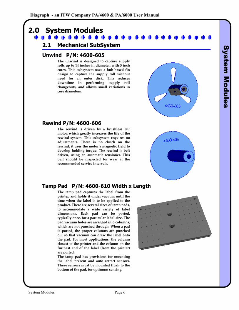
Unwind P/N: 4600-605
Rewind P/N: 4600-606
Tamp Pad P/N: 4600-610 Width x Length
The unwind is designed to capture supply rolls up to 14 inches in diameter, with 3 inch cores. This subsystem uses a hub‐based fin design to capture the supply roll without need for an outer disk. This reduces downtime in performing supply roll changeouts, and allows small variations in core diameters.
The rewind is driven by a brushless DC motor, which greatly increases the life of the rewind system. This subsystem requires no adjustments. There is no clutch on the rewind, it uses the motor’s magnetic field to develop holding torque. The rewind is belt driven, using an automatic tensioner. This belt should be inspected for wear at the recommended service intervals.
The tamp pad captures the label from the printer, and holds it under vacuum until the time when the label is to be applied to the product. There are several sizes of tamp pads, to accommodate a wide variety of label dimensions. Each pad can be ported, typically once, for a particular label size. The pad vacuum holes are arranged into columns, which are not punched through. When a pad is ported, the proper columns are punched out so that vacuum can draw the label onto the pad. For most applications, the column closest to the printer and the column on the furthest end of the label (from the printer) are ported.The tamp pad has provisions for mounting the label present and auto retract sensors. These sensors must be mounted flush to the bottom of the pad, for optimum sensing.
System Modules Page 6
Diagraph - an ITW Company PA/4600 & PA/6000 User ManualS
ystem M
odules
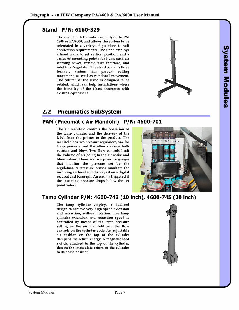
Stand P/N: 6160-329
2.2 Pneumatics SubSystem
PAM (Pneumatic Air Manifold) P/N: 4600-701
Tamp Cylinder P/N: 4600-743 (10 inch), 4600-745 (20 inch)
The stand holds the yoke assembly of the PA/4600 or PA/6000, and allows the system to be orientated in a variety of positions to suit application requirements. The stand employs a hand crank to set vertical position, and a series of mounting points for items such as: warning tower, remote user interface, and inlet filter/regulator. The stand contains three lockable casters that prevent rolling movement, as well as rotational movement. The column of the stand is designed to be rotated, which can help installations where the front leg of the t‐base interferes with existing equipment.
The air manifold controls the operation of the tamp cylinder and the delivery of the label from the printer to the product. The manifold has two pressure regulators, one for tamp pressure and the other controls both vacuum and blow. Two flow controls limit the volume of air going to the air assist and blow valves. There are two pressure gauges that monitor the pressure set by the regulators. A pressure sensor monitors the incoming air level and displays it on a digital readout and bargraph. An error is triggered if the incoming pressure drops below the set point value.
The tamp cylinder employs a dual‐rod design to achieve very high speed extension and retraction, without rotation. The tamp cylinder extension and retraction speed is controlled by means of the tamp pressure setting on the air manifold and the flow controls on the cylinder body. An adjustable air cushion on the top of the cylinder dampens the return energy. A magnetic reed switch, attached to the top of the cylinder, detects the immediate return of the cylinder to its home position.
System Modules Page 7
Diagraph - an ITW Company PA/4600 & PA/6000 User ManualS
ystem M
odules
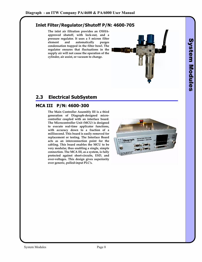
Inlet Filter/Regulator/Shutoff P/N: 4600-705
2.3 Electrical SubSystem
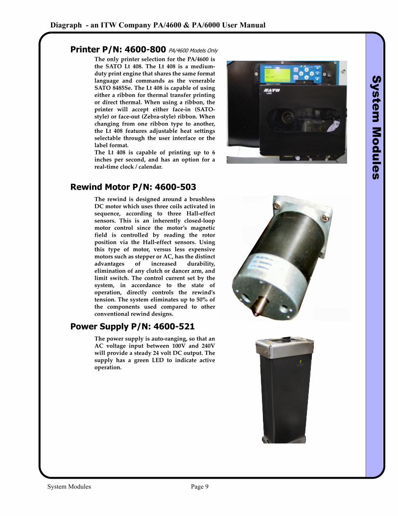
MCA III P/N: 4600-300
The inlet air filtration provides an OSHA‐approved shutoff, with lock‐out, and a pressure regulator. It uses a 5 micron filter element and automatically purges condensation trapped in the filter bowl. The regulator ensures that fluctuations in the supply air will not cause the operation of the cylinder, air assist, or vacuum to change.
The Main Controller Assembly III is a third generation of Diagraph‐designed micro‐controller coupled with an interface board. The Microcontroller Unit (MCU) is designed to execute real‐time applicator functions, with accuracy down to a fraction of a millisecond. This board is easily removed for replacement or testing. The Interface Board acts as an interconnection point for the cabling. This board enables the MCU to be very modular, thus enabling a single, simple connection. The MCA III, as a system, is fully protected against short‐circuits, ESD, and over‐voltages. This design gives superiority over generic, polled‐input PLC’s.
System Modules Page 8
Diagraph - an ITW Company PA/4600 & PA/6000 User ManualS
ystem M
odules
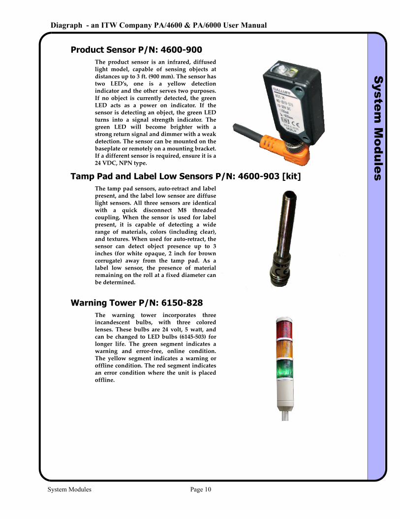
Printer P/N: 4600-800 PA/4600 Models Only
Rewind Motor P/N: 4600-503
Power Supply P/N: 4600-521
The only printer selection for the PA/4600 is the SATO Lt 408. The Lt 408 is a medium‐duty print engine that shares the same format language and commands as the venerable SATO 8485Se. The Lt 408 is capable of using either a ribbon for thermal transfer printing or direct thermal. When using a ribbon, the printer will accept either face‐in (SATO‐style) or face‐out (Zebra‐style) ribbon. When changing from one ribbon type to another, the Lt 408 features adjustable heat settings selectable through the user interface or the label format.The Lt 408 is capable of printing up to 6 inches per second, and has an option for a real‐time clock / calendar.
The rewind is designed around a brushless DC motor which uses three coils activated in sequence, according to three Hall‐effect sensors. This is an inherently closed‐loop motor control since the motor’s magnetic field is controlled by reading the rotor position via the Hall‐effect sensors. Using this type of motor, versus less expensive motors such as stepper or AC, has the distinct advantages of increased durability, elimination of any clutch or dancer arm, and limit switch. The control current set by the system, in accordance to the state of operation, directly controls the rewind’s tension. The system eliminates up to 50% of the components used compared to other conventional rewind designs.
The power supply is auto‐ranging, so that an AC voltage input between 100V and 240V will provide a steady 24 volt DC output. The supply has a green LED to indicate active operation.
System Modules Page 9
Diagraph - an ITW Company PA/4600 & PA/6000 User ManualS
ystem M
odules
Product Sensor P/N: 4600-900
Tamp Pad and Label Low Sensors P/N: 4600-903 [kit]
Warning Tower P/N: 6150-828
The product sensor is an infrared, diffused light model, capable of sensing objects at distances up to 3 ft. (900 mm). The sensor has two LED’s, one is a yellow detection indicator and the other serves two purposes. If no object is currently detected, the green LED acts as a power on indicator. If the sensor is detecting an object, the green LED turns into a signal strength indicator. The green LED will become brighter with a strong return signal and dimmer with a weak detection. The sensor can be mounted on the baseplate or remotely on a mounting bracket. If a different sensor is required, ensure it is a 24 VDC, NPN type.
The tamp pad sensors, auto‐retract and label present, and the label low sensor are diffuse light sensors. All three sensors are identical with a quick disconnect M8 threaded coupling. When the sensor is used for label present, it is capable of detecting a wide range of materials, colors (including clear), and textures. When used for auto‐retract, the sensor can detect object presence up to 3 inches (for white opaque, 2 inch for brown corrugate) away from the tamp pad. As a label low sensor, the presence of material remaining on the roll at a fixed diameter can be determined.
The warning tower incorporates three incandescent bulbs, with three colored lenses. These bulbs are 24 volt, 5 watt, and can be changed to LED bulbs (6145‐503) for longer life. The green segment indicates a warning and error‐free, online condition. The yellow segment indicates a warning or offline condition. The red segment indicates an error condition where the unit is placed offline.
System Modules Page 10
Diagraph - an ITW Company PA/4600 & PA/6000 User ManualS
ystem M
odules
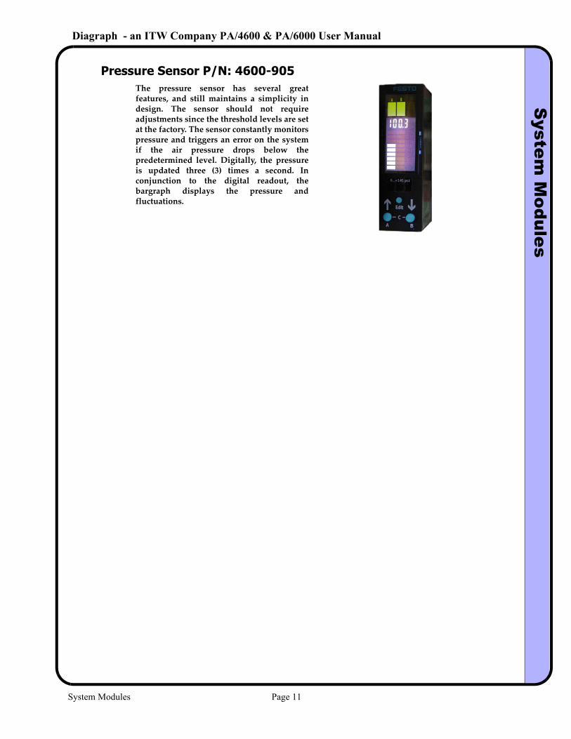
Pressure Sensor P/N: 4600-905The pressure sensor has several great features, and still maintains a simplicity in design. The sensor should not require adjustments since the threshold levels are set at the factory. The sensor constantly monitors pressure and triggers an error on the system if the air pressure drops below the predetermined level. Digitally, the pressure is updated three (3) times a second. In conjunction to the digital readout, the bargraph displays the pressure and fluctuations.
System Modules Page 11
Diagraph - an ITW Company PA/4600 & PA/6000 User ManualS
etup
3.0 Setup
Step 1 - Determine the System Orientation
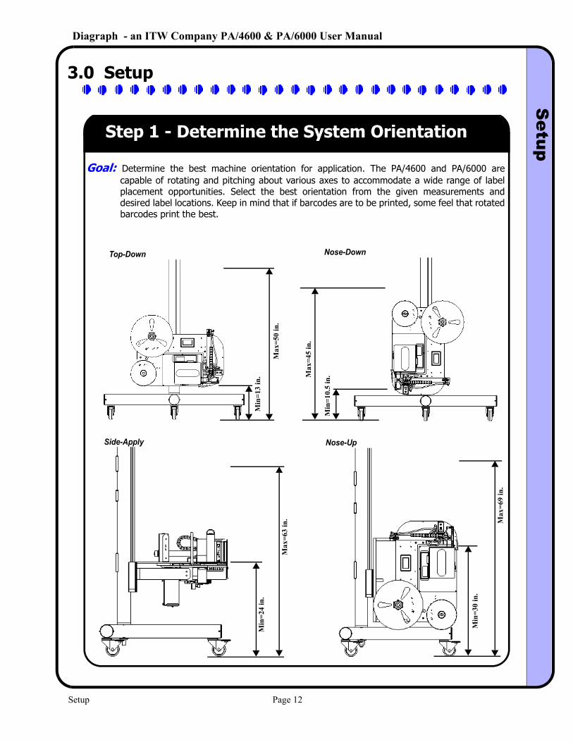
Goal: Determine the best machine orientation for application. The PA/4600 and PA/6000 are capable of rotating and pitching about various axes to accommodate a wide range of label placement opportunities. Select the best orientation from the given measurements and desired label locations. Keep in mind that if barcodes are to be printed, some feel that rotated barcodes print the best.
Top-Down
Side-Apply
Nose-Down
Nose-Up
Min
=13
in.
Max
=50
in.
Max
=45
in.
Min
=10.
5 in
.
Min
=24
in.
Max
=63
in. M
ax=6
9 in
.
Min
=30
in.
Setup Page 12
Diagraph - an ITW Company PA/4600 & PA/6000 User ManualS
etup
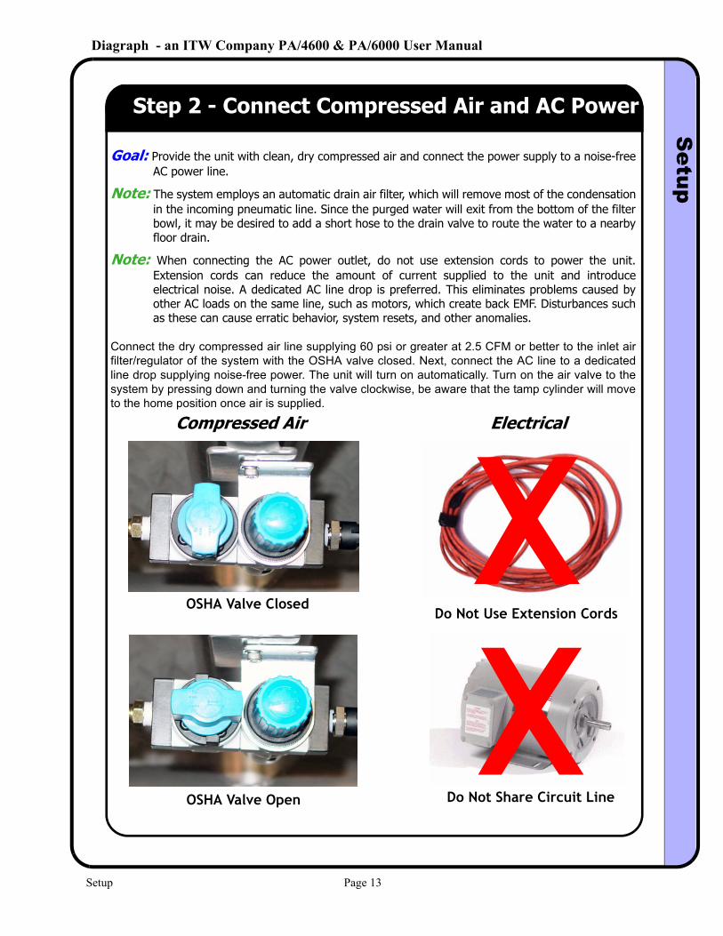
Step 2 - Connect Compressed Air and AC Power
Goal: Provide the unit with clean, dry compressed air and connect the power supply to a noise-free AC power line.
Note: The system employs an automatic drain air filter, which will remove most of the condensation in the incoming pneumatic line. Since the purged water will exit from the bottom of the filter bowl, it may be desired to add a short hose to the drain valve to route the water to a nearby floor drain.
Note: When connecting the AC power outlet, do not use extension cords to power the unit. Extension cords can reduce the amount of current supplied to the unit and introduce electrical noise. A dedicated AC line drop is preferred. This eliminates problems caused by other AC loads on the same line, such as motors, which create back EMF. Disturbances such as these can cause erratic behavior, system resets, and other anomalies.
Connect the dry compressed air line supplying 60 psi or greater at 2.5 CFM or better to the inlet air filter/regulator of the system with the OSHA valve closed. Next, connect the AC line to a dedicated line drop supplying noise-free power. The unit will turn on automatically. Turn on the air valve to the system by pressing down and turning the valve clockwise, be aware that the tamp cylinder will move to the home position once air is supplied.
Compressed Air Electrical
Do Not Use Extension Cords
Do Not Share Circuit Line
OSHA Valve Closed
OSHA Valve Open
Setup Page 13
Diagraph - an ITW Company PA/4600 & PA/6000 User ManualS
etup
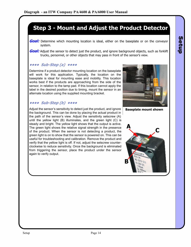
Step 3 - Mount and Adjust the Product Detector
Goal: Determine which mounting location is ideal, either on the baseplate or on the conveyor system.
Goal: Adjust the sensor to detect just the product, and ignore background objects, such as forklift trucks, personnel, or other objects that may pass in front of the sensor’s view.
•••• Sub-Step (a) •••• Determine if a product detector mounting location on the baseplate will work for this application. Typically, the location on the baseplate is ideal for mounting ease and mobility. This location works best if the products are approaching from the side of the sensor, in relation to the tamp pad. If this location cannot apply the label in the desired position due to timing, mount the sensor in an alternate location using the supplied mounting bracket.
•••• Sub-Step (b) •••• Adjust the sensor’s sensitivity to detect just the product, and ignore the background. This can be done by placing the actual product in the path of the sensor’s view. Adjust the sensitivity setscrew (A) until the yellow light (B) illuminates, and the green light (C) is steady and bright. The yellow light shows that the output is active. The green light shows the relative signal strength in the presence of the product. When the sensor is not detecting a product, the green light is on to show that the sensor is powered on. This can be useful for troubleshooting and calibration. Remove the product and verify that the yellow light is off. If not, adjust the setscrew counter-clockwise to reduce sensitivity. Once the background is eliminated from triggering the sensor, place the product under the sensor again to verify output.
Baseplate mount shown
A
B
C
Setup Page 14
Diagraph - an ITW Company PA/4600 & PA/6000 User ManualS
etup
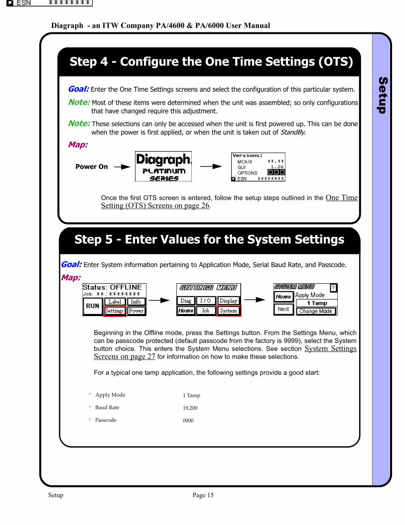
Step 4 - Configure the One Time Settings (OTS)
Goal: Enter the One Time Settings screens and select the configuration of this particular system.
Note: Most of these items were determined when the unit was assembled; so only configurations that have changed require this adjustment.
Note: These selections can only be accessed when the unit is first powered up. This can be done when the power is first applied, or when the unit is taken out of StandBy.
Map:
Once the first OTS screen is entered, follow the setup steps outlined in the One Time Setting (OTS) Screens on page 26.
Power On
Step 5 - Enter Values for the System Settings
Goal: Enter System information pertaining to Application Mode, Serial Baud Rate, and Passcode.
Map:
Beginning in the Offline mode, press the Settings button. From the Settings Menu, which can be passcode protected (default passcode from the factory is 9999), select the System button choice. This enters the System Menu selections. See section System Settings Screens on page 27 for information on how to make these selections.
For a typical one tamp application, the following settings provide a good start:
• Apply Mode 1 Tamp
• Baud Rate 19,200
• Passcode 0000
Setup Page 15
Diagraph - an ITW Company PA/4600 & PA/6000 User ManualS
etup
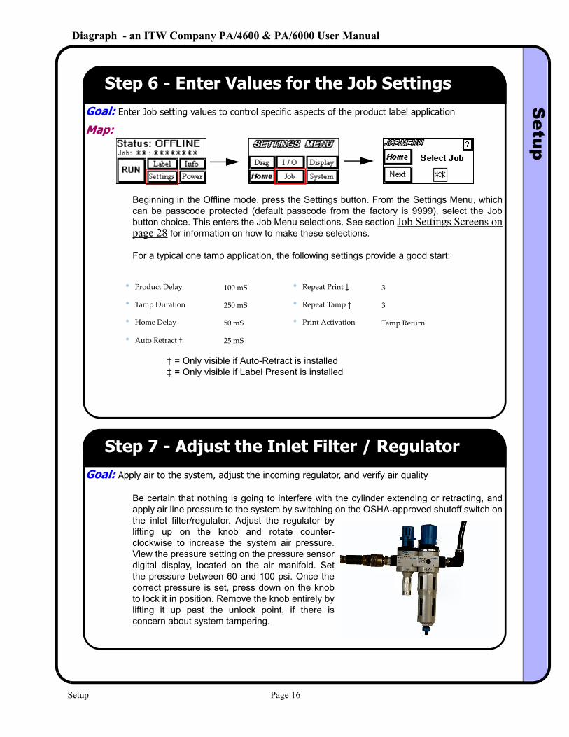
Step 6 - Enter Values for the Job SettingsGoal: Enter Job setting values to control specific aspects of the product label application
Map:
Beginning in the Offline mode, press the Settings button. From the Settings Menu, which can be passcode protected (default passcode from the factory is 9999), select the Job button choice. This enters the Job Menu selections. See section Job Settings Screens on page 28 for information on how to make these selections.
For a typical one tamp application, the following settings provide a good start:
† = Only visible if Auto-Retract is installed‡ = Only visible if Label Present is installed
• Product Delay 100 mS • Repeat Print ‡ 3
• Tamp Duration 250 mS • Repeat Tamp ‡ 3
• Home Delay 50 mS • Print Activation Tamp Return
• Auto Retract † 25 mS
Step 7 - Adjust the Inlet Filter / RegulatorGoal: Apply air to the system, adjust the incoming regulator, and verify air quality
Be certain that nothing is going to interfere with the cylinder extending or retracting, and apply air line pressure to the system by switching on the OSHA-approved shutoff switch on the inlet filter/regulator. Adjust the regulator by lifting up on the knob and rotate counter-clockwise to increase the system air pressure. View the pressure setting on the pressure sensor digital display, located on the air manifold. Set the pressure between 60 and 100 psi. Once the correct pressure is set, press down on the knob to lock it in position. Remove the knob entirely by lifting it up past the unlock point, if there is concern about system tampering.
Setup Page 16
Diagraph - an ITW Company PA/4600 & PA/6000 User ManualS
etup
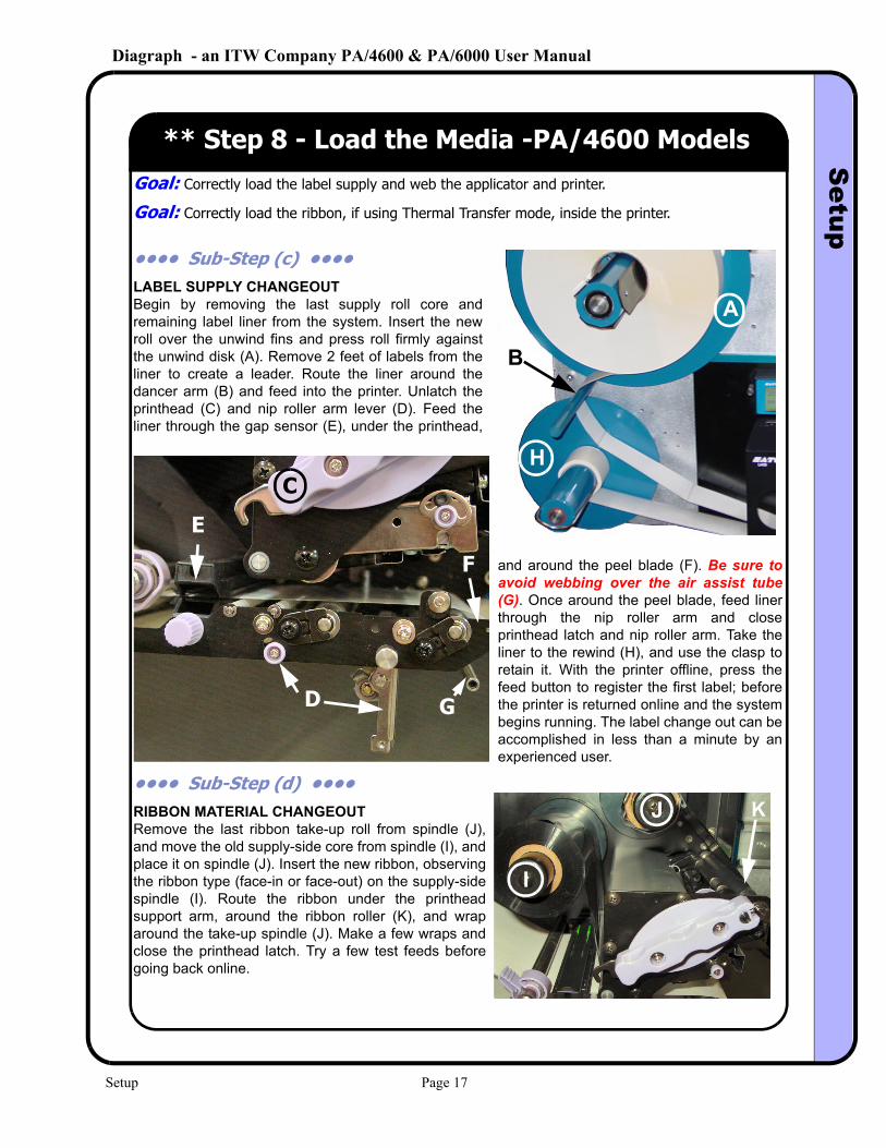
** Step 8 - Load the Media -PA/4600 ModelsGoal: Correctly load the label supply and web the applicator and printer.
Goal: Correctly load the ribbon, if using Thermal Transfer mode, inside the printer.
•••• Sub-Step (c) •••• LABEL SUPPLY CHANGEOUTBegin by removing the last supply roll core and remaining label liner from the system. Insert the new roll over the unwind fins and press roll firmly against the unwind disk (A). Remove 2 feet of labels from the liner to create a leader. Route the liner around the dancer arm (B) and feed into the printer. Unlatch the printhead (C) and nip roller arm lever (D). Feed the liner through the gap sensor (E), under the printhead,
and around the peel blade (F). Be sure to avoid webbing over the air assist tube (G). Once around the peel blade, feed liner through the nip roller arm and close printhead latch and nip roller arm. Take the liner to the rewind (H), and use the clasp to retain it. With the printer offline, press the feed button to register the first label; before the printer is returned online and the system begins running. The label change out can be accomplished in less than a minute by an experienced user.
•••• Sub-Step (d) •••• RIBBON MATERIAL CHANGEOUTRemove the last ribbon take-up roll from spindle (J), and move the old supply-side core from spindle (I), and place it on spindle (J). Insert the new ribbon, observing the ribbon type (face-in or face-out) on the supply-side spindle (I). Route the ribbon under the printhead support arm, around the ribbon roller (K), and wrap around the take-up spindle (J). Make a few wraps and close the printhead latch. Try a few test feeds before going back online.
A
B
HC
D
E
F
G
I
J K
Setup Page 17
Diagraph - an ITW Company PA/4600 & PA/6000 User ManualS
etup
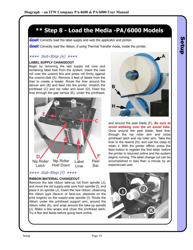
** Step 8 - Load the Media -PA/6000 ModelsGoal: Correctly load the label supply and web the applicator and printer.
Goal: Correctly load the ribbon, if using Thermal Transfer mode, inside the printer.
•••• Sub-Step (e) •••• LABEL SUPPLY CHANGEOUTBegin by removing the last supply roll core and remaining label liner from the system. Insert the new roll over the unwind fins and press roll firmly against the unwind disk (A). Remove 2 feet of labels from the liner to create a leader. Route the liner around the dancer arm (B) and feed into the printer. Unlatch the printhead (C) and nip roller arm lever (D). Feed the liner through the gap sensor (E), under the printhead,
and around the peel blade (F). Be sure to avoid webbing over the air assist tube. Once around the peel blade, feed liner through the nip roller arm and close printhead latch and nip roller arm. Take the liner to the rewind (H), and use the clasp to retain it. With the printer offline, press the feed button to register the first label; before the printer is returned online and the system begins running. The label change out can be accomplished in less than a minute by an experienced user.
•••• Sub-Step (f) •••• RIBBON MATERIAL CHANGEOUTRemove the last ribbon take-up roll from spindle (J), and move the old supply-side core from spindle (I), and place it on spindle (J). Insert the new ribbon, observing the ribbon type (face-in or face-out, depends on the print engine) on the supply-side spindle (I). Route the ribbon under the printhead support arm, around the ribbon roller (K), and wrap around the take-up spindle (J). Make a few wraps and close the printhead latch. Try a few test feeds before going back online.
A
B
H
C
D
E
F
GF
I
J K
JI
K
Setup Page 18
Diagraph - an ITW Company PA/4600 & PA/6000 User ManualS
etup
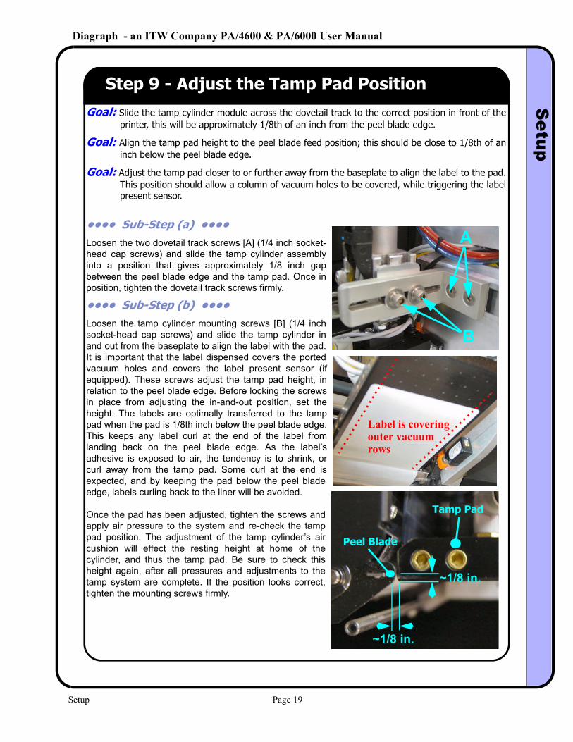
Step 9 - Adjust the Tamp Pad PositionGoal: Slide the tamp cylinder module across the dovetail track to the correct position in front of the
printer, this will be approximately 1/8th of an inch from the peel blade edge.
Goal: Align the tamp pad height to the peel blade feed position; this should be close to 1/8th of an inch below the peel blade edge.
Goal: Adjust the tamp pad closer to or further away from the baseplate to align the label to the pad. This position should allow a column of vacuum holes to be covered, while triggering the label present sensor.
•••• Sub-Step (a) •••• Loosen the two dovetail track screws [A] (1/4 inch socket-head cap screws) and slide the tamp cylinder assembly into a position that gives approximately 1/8 inch gap between the peel blade edge and the tamp pad. Once in position, tighten the dovetail track screws firmly.
•••• Sub-Step (b) •••• Loosen the tamp cylinder mounting screws [B] (1/4 inch socket-head cap screws) and slide the tamp cylinder in and out from the baseplate to align the label with the pad. It is important that the label dispensed covers the ported vacuum holes and covers the label present sensor (if equipped). These screws adjust the tamp pad height, in relation to the peel blade edge. Before locking the screws in place from adjusting the in-and-out position, set the height. The labels are optimally transferred to the tamp pad when the pad is 1/8th inch below the peel blade edge. This keeps any label curl at the end of the label from landing back on the peel blade edge. As the label’s adhesive is exposed to air, the tendency is to shrink, or curl away from the tamp pad. Some curl at the end is expected, and by keeping the pad below the peel blade edge, labels curling back to the liner will be avoided.
Once the pad has been adjusted, tighten the screws and apply air pressure to the system and re-check the tamp pad position. The adjustment of the tamp cylinder’s air cushion will effect the resting height at home of the cylinder, and thus the tamp pad. Be sure to check this height again, after all pressures and adjustments to the tamp system are complete. If the position looks correct, tighten the mounting screws firmly.
~1/8 in.
~1/8 in.
Peel Blade
Tamp Pad
A
B
Label is coveringouter vacuumrows
Setup Page 19
Diagraph - an ITW Company PA/4600 & PA/6000 User ManualS
etup
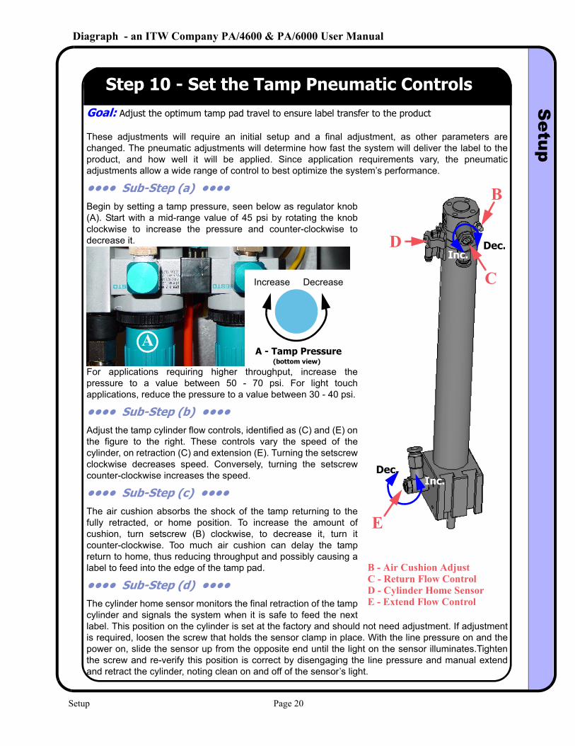
Step 10 - Set the Tamp Pneumatic ControlsGoal: Adjust the optimum tamp pad travel to ensure label transfer to the product
These adjustments will require an initial setup and a final adjustment, as other parameters are changed. The pneumatic adjustments will determine how fast the system will deliver the label to the product, and how well it will be applied. Since application requirements vary, the pneumatic adjustments allow a wide range of control to best optimize the system’s performance.
•••• Sub-Step (a) •••• Begin by setting a tamp pressure, seen below as regulator knob (A). Start with a mid-range value of 45 psi by rotating the knob clockwise to increase the pressure and counter-clockwise to decrease it.
For applications requiring higher throughput, increase the pressure to a value between 50 - 70 psi. For light touch applications, reduce the pressure to a value between 30 - 40 psi.
•••• Sub-Step (b) •••• Adjust the tamp cylinder flow controls, identified as (C) and (E) on the figure to the right. These controls vary the speed of the cylinder, on retraction (C) and extension (E). Turning the setscrew clockwise decreases speed. Conversely, turning the setscrew counter-clockwise increases the speed.
•••• Sub-Step (c) •••• The air cushion absorbs the shock of the tamp returning to the fully retracted, or home position. To increase the amount of cushion, turn setscrew (B) clockwise, to decrease it, turn it counter-clockwise. Too much air cushion can delay the tamp return to home, thus reducing throughput and possibly causing a label to feed into the edge of the tamp pad.
•••• Sub-Step (d) •••• The cylinder home sensor monitors the final retraction of the tamp cylinder and signals the system when it is safe to feed the next label. This position on the cylinder is set at the factory and should not need adjustment. If adjustment is required, loosen the screw that holds the sensor clamp in place. With the line pressure on and the power on, slide the sensor up from the opposite end until the light on the sensor illuminates.Tighten the screw and re-verify this position is correct by disengaging the line pressure and manual extend and retract the cylinder, noting clean on and off of the sensor’s light.
A
Increase Decrease
A - Tamp Pressure(bottom view)
B
C
D
E
B - Air Cushion AdjustC - Return Flow ControlD - Cylinder Home SensorE - Extend Flow Control
Inc.Dec.
Inc.Dec.
Setup Page 20
Diagraph - an ITW Company PA/4600 & PA/6000 User ManualS
etup
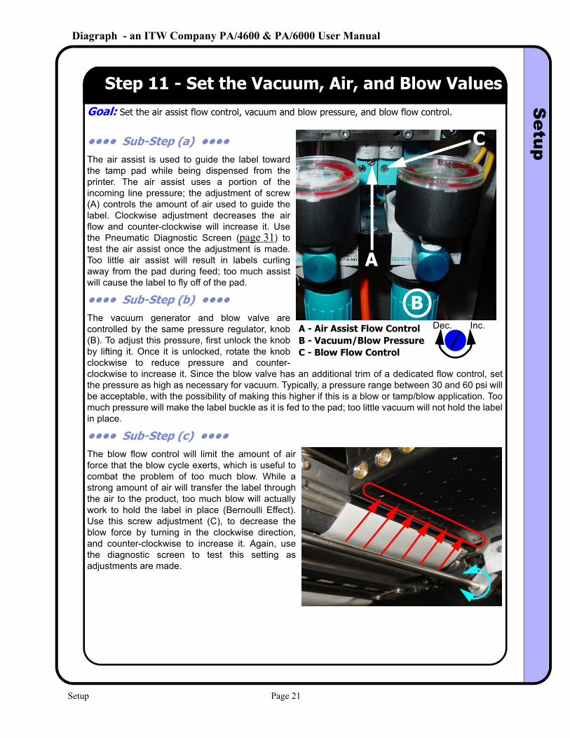
Step 11 - Set the Vacuum, Air, and Blow ValuesGoal: Set the air assist flow control, vacuum and blow pressure, and blow flow control.
•••• Sub-Step (a) •••• The air assist is used to guide the label toward the tamp pad while being dispensed from the printer. The air assist uses a portion of the incoming line pressure; the adjustment of screw (A) controls the amount of air used to guide the label. Clockwise adjustment decreases the air flow and counter-clockwise will increase it. Use the Pneumatic Diagnostic Screen (page 31) to test the air assist once the adjustment is made. Too little air assist will result in labels curling away from the pad during feed; too much assist will cause the label to fly off of the pad.
•••• Sub-Step (b) •••• The vacuum generator and blow valve are controlled by the same pressure regulator, knob (B). To adjust this pressure, first unlock the knob by lifting it. Once it is unlocked, rotate the knob clockwise to reduce pressure and counter-clockwise to increase it. Since the blow valve has an additional trim of a dedicated flow control, set the pressure as high as necessary for vacuum. Typically, a pressure range between 30 and 60 psi will be acceptable, with the possibility of making this higher if this is a blow or tamp/blow application. Too much pressure will make the label buckle as it is fed to the pad; too little vacuum will not hold the label in place.
•••• Sub-Step (c) •••• The blow flow control will limit the amount of air force that the blow cycle exerts, which is useful to combat the problem of too much blow. While a strong amount of air will transfer the label through the air to the product, too much blow will actually work to hold the label in place (Bernoulli Effect). Use this screw adjustment (C), to decrease the blow force by turning in the clockwise direction, and counter-clockwise to increase it. Again, use the diagnostic screen to test this setting as adjustments are made.
A
C
BA - Air Assist Flow Control
C - Blow Flow ControlB - Vacuum/Blow Pressure
Dec. Inc.
Setup Page 21
Diagraph - an ITW Company PA/4600 & PA/6000 User ManualS
etup
Step 12 - Test PrintGoal: Verify communications between the applicator and the printer
Goal: Optimize the printer image offset on the label, print darkness, presentation of the label out of the printer (pitch), and print quality.
•••• Sub-Step (a) •••• Begin by setting the desired baud rate in the printer, and in the PA/4600 or PA/6000. Typically, applications run well at 19,200 baud since this rate allows more immunity to signal noise and can allow greater cable distances. For applications that demand higher throughput, higher serial speeds or Ethernet may be required. Select the baud rate for the system from the menu seen on page 27.
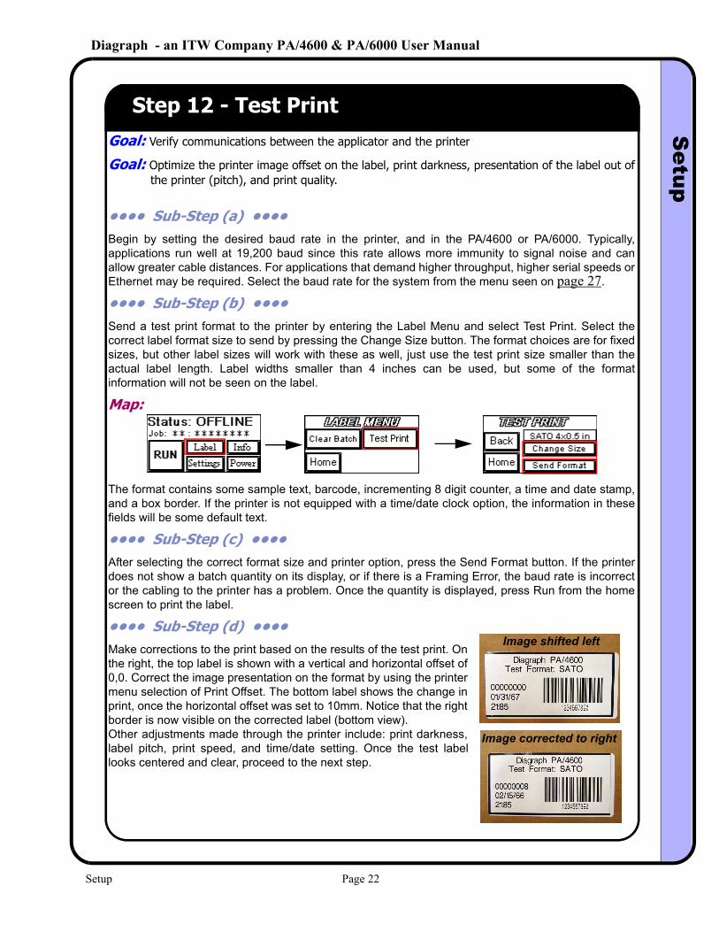
•••• Sub-Step (b) •••• Send a test print format to the printer by entering the Label Menu and select Test Print. Select the correct label format size to send by pressing the Change Size button. The format choices are for fixed sizes, but other label sizes will work with these as well, just use the test print size smaller than the actual label length. Label widths smaller than 4 inches can be used, but some of the format information will not be seen on the label.
Map:
The format contains some sample text, barcode, incrementing 8 digit counter, a time and date stamp, and a box border. If the printer is not equipped with a time/date clock option, the information in these fields will be some default text.
•••• Sub-Step (c) •••• After selecting the correct format size and printer option, press the Send Format button. If the printer does not show a batch quantity on its display, or if there is a Framing Error, the baud rate is incorrect or the cabling to the printer has a problem. Once the quantity is displayed, press Run from the home screen to print the label.
•••• Sub-Step (d) •••• Make corrections to the print based on the results of the test print. On the right, the top label is shown with a vertical and horizontal offset of 0,0. Correct the image presentation on the format by using the printer menu selection of Print Offset. The bottom label shows the change in print, once the horizontal offset was set to 10mm. Notice that the right border is now visible on the corrected label (bottom view).Other adjustments made through the printer include: print darkness, label pitch, print speed, and time/date setting. Once the test label looks centered and clear, proceed to the next step.
Image shifted left
Image corrected to right
Setup Page 22
Diagraph - an ITW Company PA/4600 & PA/6000 User ManualS
etup
Step 13 - Create a Format and DownloadGoal: Create a simple format, set the correct communications parameters, and send a format down
to the system.
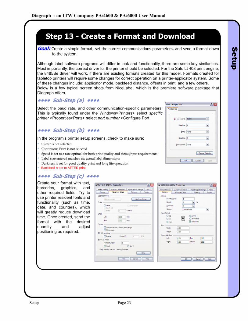
Although label software programs will differ in look and functionality, there are some key similarities. Most importantly, the correct driver for the printer should be selected. For the Sato Lt 408 print engine, the 8485Se driver will work, if there are existing formats created for this model. Formats created for tabletop printers will require some changes for correct operation on a printer-applicator system. Some of these changes include: applicator mode, backfeed distance, offsets in print, and a few others. Below is a few typical screen shots from NiceLabel, which is the premiere software package that Diagraph offers.
•••• Sub-Step (a) •••• Select the baud rate, and other communication-specific parameters. This is typically found under the Windows>Printers> select specific printer >Properties>Ports> select port number >Configure Port
•••• Sub-Step (b) •••• In the program’s printer setup screens, check to make sure:• Cutter is not selected• Continuous Print is not selected• Speed is set to a rate optimal for both print quality and throughput requirements• Label size entered matches the actual label dimensions• Darkness is set for good quality print and long life operation
•••• Sub-Step (c) •••• Create your format with text, barcodes, graphics, and other required fields. Try to use printer resident fonts and functionality (such as time, date, and counters), which will greatly reduce download time. Once created, send the format with the desired quantity and adjust positioning as required.
• Backfeed is set to AFTER print
Setup Page 23
Diagraph - an ITW Company PA/4600 & PA/6000 User ManualS
etup
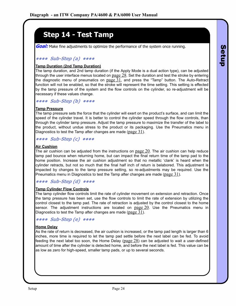
Step 14 - Test TampGoal: Make fine adjustments to optimize the performance of the system once running.
•••• Sub-Step (a) •••• Tamp Duration (2nd Tamp Duration)The tamp duration, and 2nd tamp duration (if the Apply Mode is a dual action type), can be adjusted through the user interface menus located on page 28. Set the duration and test the stroke by entering the diagnostic menu of pneumatics on page 31, and press the “Tamp” button. The Auto-Retract function will not be enabled, so that the stroke will represent the time setting. This setting is effected by the tamp pressure of the system and the flow controls on the cylinder, so re-adjustment will be necessary if these values change.
•••• Sub-Step (b) •••• Tamp PressureThe tamp pressure sets the force that the cylinder will exert on the product’s surface, and can limit the speed of the cylinder travel. It is better to control the cylinder speed through the flow controls, than through the cylinder tamp pressure. Adjust the tamp pressure to maximize the transfer of the label to the product, without undue stress to the product or its packaging. Use the Pneumatics menu in Diagnostics to test the Tamp after changes are made (page 31).
•••• Sub-Step (c) •••• Air CushionThe air cushion can be adjusted from the instructions on page 20. The air cushion can help reduce tamp pad bounce when returning home, but can impact the final return time of the tamp pad to the home position. Increase the air cushion adjustment so that no metallic ‘clank’ is heard when the cylinder retracts, but not so much that the final half inch of return is belabored. This adjustment is impacted by changes to the tamp pressure setting, so re-adjustments may be required. Use the Pneumatics menu in Diagnostics to test the Tamp after changes are made (page 31).
•••• Sub-Step (d) •••• Tamp Cylinder Flow ControlsThe tamp cylinder flow controls limit the rate of cylinder movement on extension and retraction. Once the tamp pressure has been set, use the flow controls to limit the rate of extension by utilizing the control closest to the tamp pad. The rate of retraction is adjusted by the control closest to the home sensor. The adjustment instructions are located on page 20. Use the Pneumatics menu in Diagnostics to test the Tamp after changes are made (page 31).
•••• Sub-Step (e) •••• Home DelayAs the rate of return is decreased, the air cushion is increased, or the tamp pad length is larger than 6 inches, more time is required to let the tamp pad settle before the next label can be fed. To avoid feeding the next label too soon, the Home Delay (page 28) can be adjusted to wait a user-defined amount of time after the cylinder is detected home, and before the next label is fed. This value can be as low as zero for high-speed, smaller tamp pads, or up to several seconds.
Setup Page 24
Diagraph - an ITW Company PA/4600 & PA/6000 User ManualS
etup
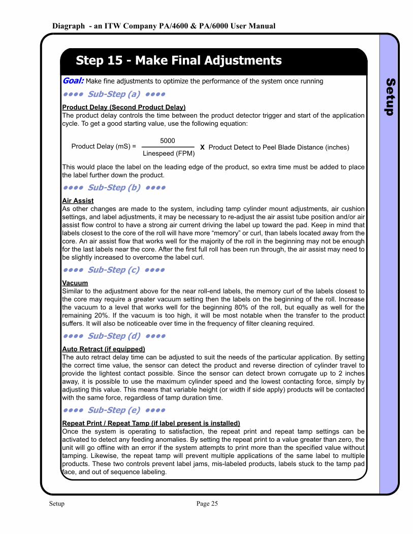
Step 15 - Make Final AdjustmentsGoal: Make fine adjustments to optimize the performance of the system once running
•••• Sub-Step (a) •••• Product Delay (Second Product Delay)The product delay controls the time between the product detector trigger and start of the application cycle. To get a good starting value, use the following equation:
This would place the label on the leading edge of the product, so extra time must be added to place the label further down the product.
•••• Sub-Step (b) •••• Air AssistAs other changes are made to the system, including tamp cylinder mount adjustments, air cushion settings, and label adjustments, it may be necessary to re-adjust the air assist tube position and/or air assist flow control to have a strong air current driving the label up toward the pad. Keep in mind that labels closest to the core of the roll will have more “memory” or curl, than labels located away from the core. An air assist flow that works well for the majority of the roll in the beginning may not be enough for the last labels near the core. After the first full roll has been run through, the air assist may need to be slightly increased to overcome the label curl.
•••• Sub-Step (c) •••• VacuumSimilar to the adjustment above for the near roll-end labels, the memory curl of the labels closest to the core may require a greater vacuum setting then the labels on the beginning of the roll. Increase the vacuum to a level that works well for the beginning 80% of the roll, but equally as well for the remaining 20%. If the vacuum is too high, it will be most notable when the transfer to the product suffers. It will also be noticeable over time in the frequency of filter cleaning required.
•••• Sub-Step (d) •••• Auto Retract (if equipped)The auto retract delay time can be adjusted to suit the needs of the particular application. By setting the correct time value, the sensor can detect the product and reverse direction of cylinder travel to provide the lightest contact possible. Since the sensor can detect brown corrugate up to 2 inches away, it is possible to use the maximum cylinder speed and the lowest contacting force, simply by adjusting this value. This means that variable height (or width if side apply) products will be contacted with the same force, regardless of tamp duration time.
•••• Sub-Step (e) •••• Repeat Print / Repeat Tamp (if label present is installed)Once the system is operating to satisfaction, the repeat print and repeat tamp settings can be activated to detect any feeding anomalies. By setting the repeat print to a value greater than zero, the unit will go offline with an error if the system attempts to print more than the specified value without tamping. Likewise, the repeat tamp will prevent multiple applications of the same label to multiple products. These two controls prevent label jams, mis-labeled products, labels stuck to the tamp pad face, and out of sequence labeling.
Product Delay (mS) = 5000
Linespeed (FPM) Product Detect to Peel Blade Distance (inches)X
Setup Page 25
Diagraph - an ITW Company PA/4600 & PA/6000 User ManualU
ser Interface
4.0 User Interface
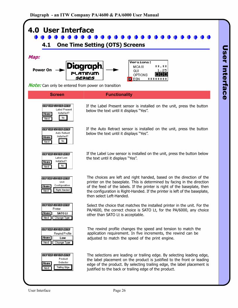
4.1 One Time Setting (OTS) Screens
Map:
Power On
Note: Can only be entered from power on transition
If the Label Present sensor is installed on the unit, press the button below the text until it displays “Yes”.
If the Auto Retract sensor is installed on the unit, press the button below the text until it displays “Yes”.
If the Label Low sensor is installed on the unit, press the button below the text until it displays “Yes”.
The choices are left and right handed, based on the direction of the printer on the baseplate. This is determined by facing in the direction of the feed of the labels. If the printer is right of the baseplate, then the configuration is Right-Handed. If the printer is left of the baseplate, then select Left-Handed.
Select the choice that matches the installed printer in the unit. For the PA/4600, the correct choice is SATO Lt, for the PA/6000, any choice other than SATO Lt is acceptable.
The selections are leading or trailing edge. By selecting leading edge, the label placement on the product is justified to the front or leading edge of the product. By selecting trailing edge, the label placement is justified to the back or trailing edge of the product.
Screen Functionality
The rewind profile changes the speed and tension to match theapplication requirement. In five increments, the rewind can beadjusted to match the speed of the print engine.
User Interface Page 26
Diagraph - an ITW Company PA/4600 & PA/6000 User ManualU
ser Interface
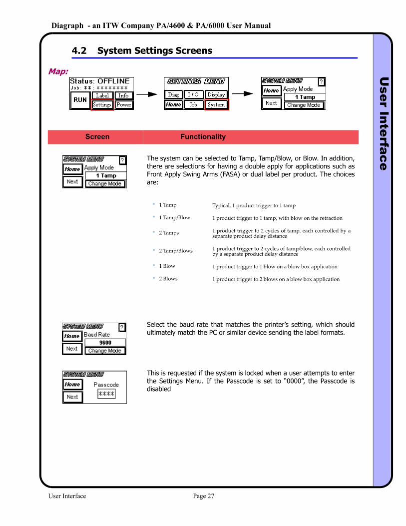
4.2 System Settings Screens
Map:
The system can be selected to Tamp, Tamp/Blow, or Blow. In addition, there are selections for having a double apply for applications such as Front Apply Swing Arms (FASA) or dual label per product. The choices are:
• 1 Tamp Typical, 1 product trigger to 1 tamp
• 1 Tamp/Blow 1 product trigger to 1 tamp, with blow on the retraction
• 2 Tamps 1 product trigger to 2 cycles of tamp, each controlled by a separate product delay distance
• 2 Tamp/Blows 1 product trigger to 2 cycles of tamp/blow, each controlled by a separate product delay distance
• 1 Blow 1 product trigger to 1 blow on a blow box application
• 2 Blows 1 product trigger to 2 blows on a blow box application
Select the baud rate that matches the printer’s setting, which should ultimately match the PC or similar device sending the label formats.
This is requested if the system is locked when a user attempts to enter the Settings Menu. If the Passcode is set to “0000”, the Passcode is disabled
Screen Functionality
User Interface Page 27
Diagraph - an ITW Company PA/4600 & PA/6000 User ManualU
ser Interface
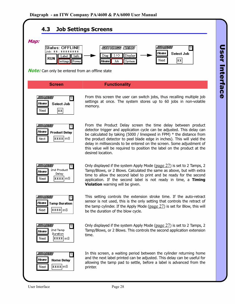
4.3 Job Settings Screens
Map:
Note: Can only be entered from an offline state
Screen Functionality
From this screen the user can switch jobs, thus recalling multiple job settings at once. The system stores up to 60 jobs in non-volatile memory.
From the Product Delay screen the time delay between product detector trigger and application cycle can be adjusted. This delay can be calculated by taking (5000 / linespeed in FPM) * the distance from the product detector to peel blade edge in inches). This will yield the delay in milliseconds to be entered on the screen. Some adjustment of this value will be required to position the label on the product at the desired location.
Only displayed if the system Apply Mode (page 27) is set to 2 Tamps, 2 Tamp/Blows, or 2 Blows. Calculated the same as above, but with extra time to allow the second label to print and be ready for the second application. If the second label is not ready in time, a Timing Violation warning will be given.
This setting controls the extension stroke time. If the auto-retract sensor is not used, this is the only setting that controls the retract of the tamp cylinder. If the Apply Mode (page 27) is set for Blow, this will be the duration of the blow cycle.
Only displayed if the system Apply Mode (page 27) is set to 2 Tamps, 2 Tamp/Blows, or 2 Blows. This controls the second application extension time.
In this screen, a waiting period between the cylinder returning home and the next label printed can be adjusted. This delay can be useful for allowing the tamp pad to settle, before a label is advanced from the printer.
User Interface Page 28
Diagraph - an ITW Company PA/4600 & PA/6000 User ManualU
ser Interface
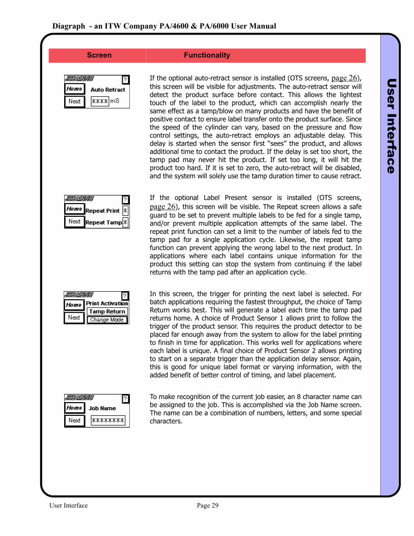
If the optional auto-retract sensor is installed (OTS screens, page 26), this screen will be visible for adjustments. The auto-retract sensor will detect the product surface before contact. This allows the lightest touch of the label to the product, which can accomplish nearly the same effect as a tamp/blow on many products and have the benefit of positive contact to ensure label transfer onto the product surface. Since the speed of the cylinder can vary, based on the pressure and flow control settings, the auto-retract employs an adjustable delay. This delay is started when the sensor first “sees” the product, and allows additional time to contact the product. If the delay is set too short, the tamp pad may never hit the product. If set too long, it will hit the product too hard. If it is set to zero, the auto-retract will be disabled, and the system will solely use the tamp duration timer to cause retract.
If the optional Label Present sensor is installed (OTS screens, page 26), this screen will be visible. The Repeat screen allows a safe guard to be set to prevent multiple labels to be fed for a single tamp, and/or prevent multiple application attempts of the same label. The repeat print function can set a limit to the number of labels fed to the tamp pad for a single application cycle. Likewise, the repeat tamp function can prevent applying the wrong label to the next product. In applications where each label contains unique information for the product this setting can stop the system from continuing if the label returns with the tamp pad after an application cycle.
In this screen, the trigger for printing the next label is selected. For batch applications requiring the fastest throughput, the choice of Tamp Return works best. This will generate a label each time the tamp pad returns home. A choice of Product Sensor 1 allows print to follow the trigger of the product sensor. This requires the product detector to be placed far enough away from the system to allow for the label printing to finish in time for application. This works well for applications where each label is unique. A final choice of Product Sensor 2 allows printing to start on a separate trigger than the application delay sensor. Again, this is good for unique label format or varying information, with the added benefit of better control of timing, and label placement.
To make recognition of the current job easier, an 8 character name can be assigned to the job. This is accomplished via the Job Name screen. The name can be a combination of numbers, letters, and some special characters.
Screen Functionality
User Interface Page 29
Diagraph - an ITW Company PA/4600 & PA/6000 User ManualU
ser Interface
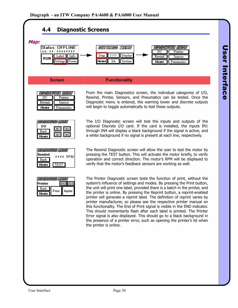
4.4 Diagnostic Screens
Map:
Screen Functionality
From the main Diagnostics screen, the individual categories of I/O, Rewind, Printer, Sensors, and Pneumatics can be tested. Once the Diagnostic menu is entered, the warning tower and discrete outputs will begin to toggle automatically to test these outputs.
The I/O Diagnostic screen will test the inputs and outputs of the optional Discrete I/O card. If the card is installed, the inputs IN1 through IN4 will display a black background if the signal is active, and a white background if no signal is present at each line, respectively.
The Rewind Diagnostic screen will allow the user to test the motor by pressing the TEST button. This will activate the motor briefly, to verify operation and correct direction. The motor’s RPM will be displayed to verify that the motor’s feedback sensors are working as well.
The Printer Diagnostic screen tests the function of print, without the system’s influence of settings and modes. By pressing the Print button, the unit will print one label, provided there is a batch in the printer, and the printer is online. By pressing the Reprint button, a reprint-enabled printer will generate a reprint label. The definition of reprint varies by printer manufacturer, so please see the respective printer manual on this functionality. The End of Print signal is visible in the END indicator. This should momentarily flash after each label is printed. The Printer Error signal is also displayed. This should go to a black background in the presence of a printer error, such as opening the printer’s lid when the printer is online.
User Interface Page 30
Diagraph - an ITW Company PA/4600 & PA/6000 User ManualU
ser Interface
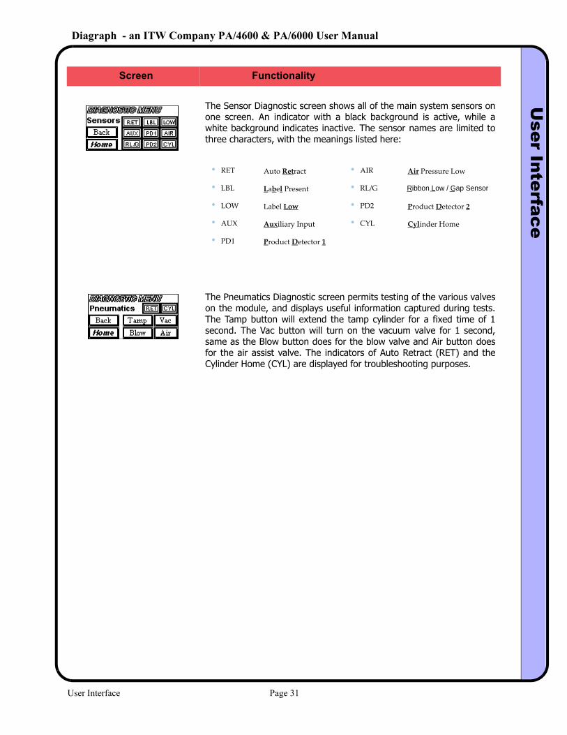
The Sensor Diagnostic screen shows all of the main system sensors on one screen. An indicator with a black background is active, while a white background indicates inactive. The sensor names are limited to three characters, with the meanings listed here:
• RET Auto Retract • AIR Air Pressure Low
• LBL Label Present • RL/G Ribbon Low / Gap Sensor
• LOW Label Low • PD2 Product Detector 2
• AUX Auxiliary Input • CYL Cylinder Home
• PD1 Product Detector 1
The Pneumatics Diagnostic screen permits testing of the various valves on the module, and displays useful information captured during tests. The Tamp button will extend the tamp cylinder for a fixed time of 1 second. The Vac button will turn on the vacuum valve for 1 second, same as the Blow button does for the blow valve and Air button does for the air assist valve. The indicators of Auto Retract (RET) and the Cylinder Home (CYL) are displayed for troubleshooting purposes.
Screen Functionality
User Interface Page 31
Diagraph - an ITW Company PA/4600 & PA/6000 User ManualU
ser Interface
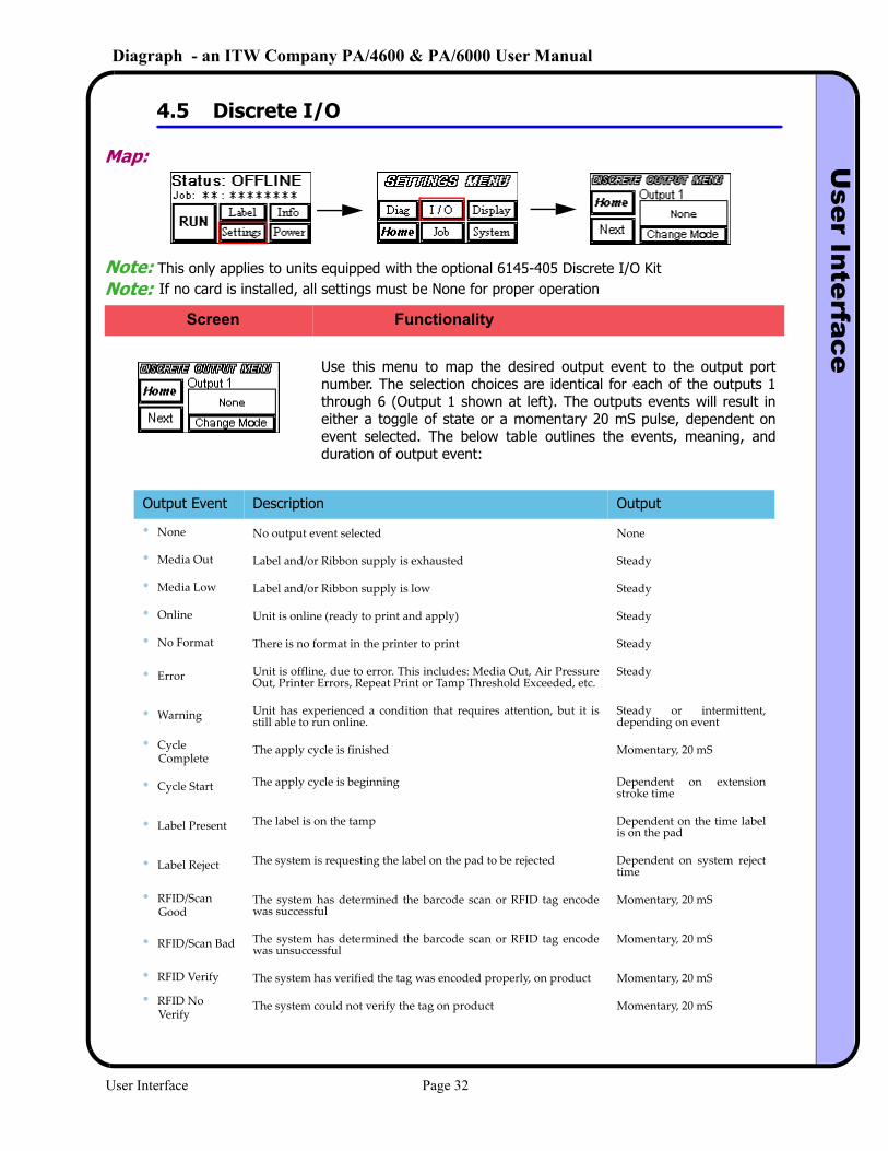
4.5 Discrete I/O
Map:
Note: This only applies to units equipped with the optional 6145-405 Discrete I/O Kit
Screen Functionality
Use this menu to map the desired output event to the output port number. The selection choices are identical for each of the outputs 1 through 6 (Output 1 shown at left). The outputs events will result in either a toggle of state or a momentary 20 mS pulse, dependent on event selected. The below table outlines the events, meaning, and duration of output event:
Output Event Description Output
• None No output event selected None
• Media Out Label and/or Ribbon supply is exhausted Steady
• Media Low Label and/or Ribbon supply is low Steady
• Online Unit is online (ready to print and apply) Steady
• No Format There is no format in the printer to print Steady
• Error Unit is offline, due to error. This includes: Media Out, Air Pressure Out, Printer Errors, Repeat Print or Tamp Threshold Exceeded, etc.
Steady
• Warning Unit has experienced a condition that requires attention, but it is still able to run online.
Steady or intermittent, depending on event
• Cycle Complete
The apply cycle is finished Momentary, 20 mS
• Cycle Start The apply cycle is beginning Dependent on extension stroke time
• Label Present The label is on the tamp Dependent on the time label is on the pad
• Label Reject The system is requesting the label on the pad to be rejected Dependent on system reject time
• RFID/Scan Good
The system has determined the barcode scan or RFID tag encode was successful
Momentary, 20 mS
• RFID/Scan Bad The system has determined the barcode scan or RFID tag encode was unsuccessful
Momentary, 20 mS
• RFID Verify The system has verified the tag was encoded properly, on product Momentary, 20 mS
• RFID No Verify
The system could not verify the tag on product Momentary, 20 mS
Note: If no card is installed, all settings must be None for proper operation
User Interface Page 32
Diagraph - an ITW Company PA/4600 & PA/6000 User ManualU
ser Interface
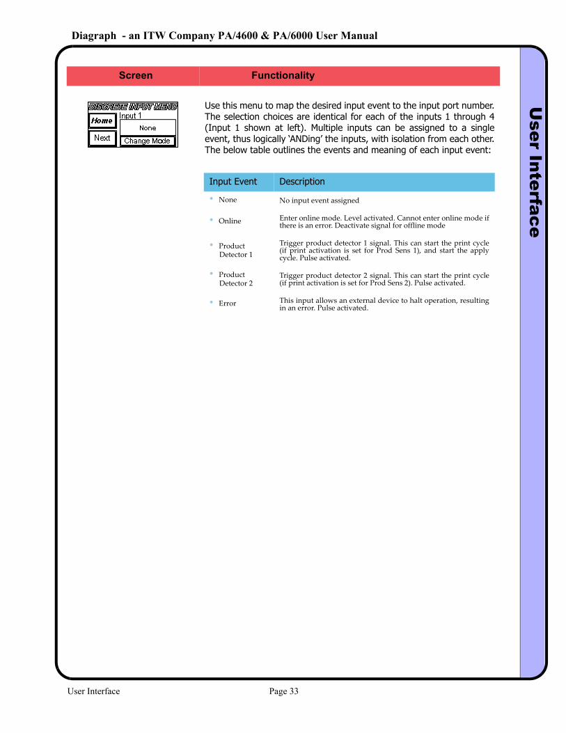
Use this menu to map the desired input event to the input port number. The selection choices are identical for each of the inputs 1 through 4 (Input 1 shown at left). Multiple inputs can be assigned to a single event, thus logically ‘ANDing’ the inputs, with isolation from each other. The below table outlines the events and meaning of each input event:
Screen Functionality
Input Event Description
• None No input event assigned
• Online Enter online mode. Level activated. Cannot enter online mode if there is an error. Deactivate signal for offline mode
• Product Detector 1
Trigger product detector 1 signal. This can start the print cycle (if print activation is set for Prod Sens 1), and start the apply cycle. Pulse activated.
• Product Detector 2
Trigger product detector 2 signal. This can start the print cycle (if print activation is set for Prod Sens 2). Pulse activated.
• Error This input allows an external device to halt operation, resulting in an error. Pulse activated.
User Interface Page 33
Diagraph - an ITW Company PA/4600 & PA/6000 User ManualU
ser Interface
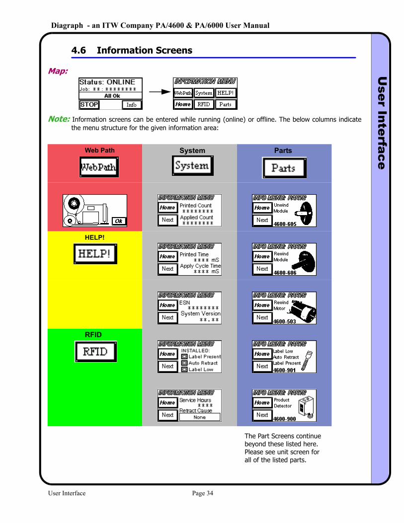
4.6 Information Screens
Map:
Note: Information screens can be entered while running (online) or offline. The below columns indicate the menu structure for the given information area:
Web Path System Parts
HELP!
RFID
The Part Screens continuebeyond these listed here.Please see unit screen forall of the listed parts.
User Interface Page 34
Diagraph - an ITW Company PA/4600 & PA/6000 User ManualU
ser Interface
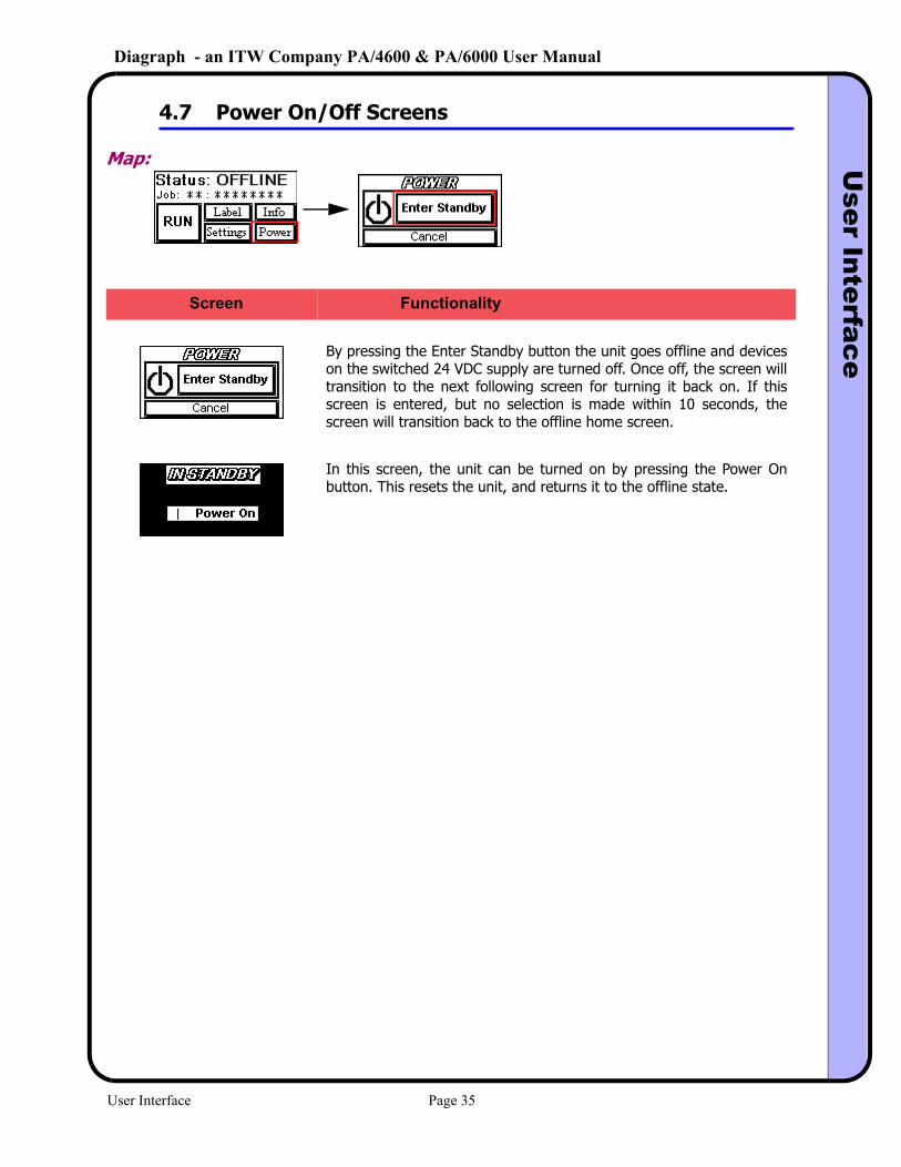
4.7 Power On/Off Screens
Map:
By pressing the Enter Standby button the unit goes offline and devices on the switched 24 VDC supply are turned off. Once off, the screen will transition to the next following screen for turning it back on. If this screen is entered, but no selection is made within 10 seconds, the screen will transition back to the offline home screen.
In this screen, the unit can be turned on by pressing the Power On button. This resets the unit, and returns it to the offline state.
Screen Functionality
User Interface Page 35
Diagraph - an ITW Company PA/4600 & PA/6000 User ManualTroubleshooting
5.0 Troubleshooting
5.1 System Warnings
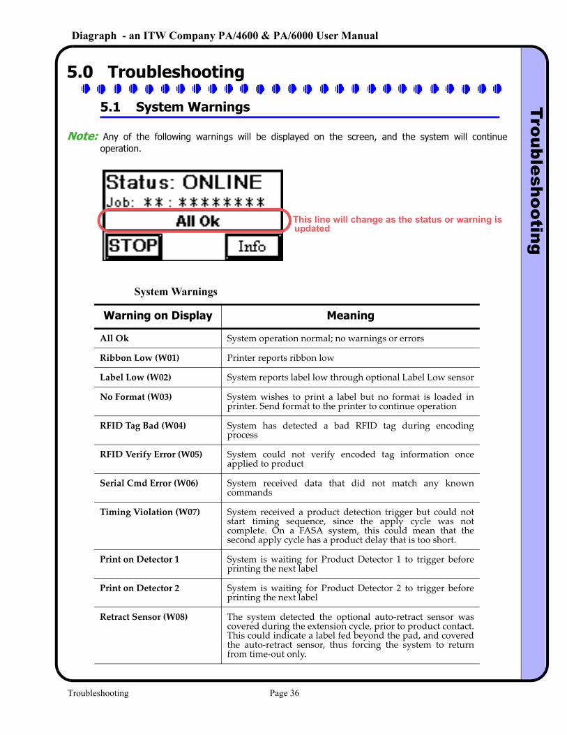
Note: Any of the following warnings will be displayed on the screen, and the system will continue operation.
System Warnings
Warning on Display Meaning
All Ok System operation normal; no warnings or errors
Ribbon Low (W01) Printer reports ribbon low
Label Low (W02) System reports label low through optional Label Low sensor
No Format (W03) System wishes to print a label but no format is loaded in printer. Send format to the printer to continue operation
RFID Tag Bad (W04) System has detected a bad RFID tag during encoding process
RFID Verify Error (W05) System could not verify encoded tag information once applied to product
Serial Cmd Error (W06) System received data that did not match any known commands
Timing Violation (W07) System received a product detection trigger but could not start timing sequence, since the apply cycle was not complete. On a FASA system, this could mean that the second apply cycle has a product delay that is too short.
Print on Detector 1 System is waiting for Product Detector 1 to trigger before printing the next label
Print on Detector 2 System is waiting for Product Detector 2 to trigger before printing the next label
Retract Sensor (W08) The system detected the optional auto‐retract sensor was covered during the extension cycle, prior to product contact. This could indicate a label fed beyond the pad, and covered the auto‐retract sensor, thus forcing the system to return from time‐out only.
This line will change as the status or warning isupdated
Troubleshooting Page 36
Diagraph - an ITW Company PA/4600 & PA/6000 User ManualTroubleshooting
5.2 System Errors
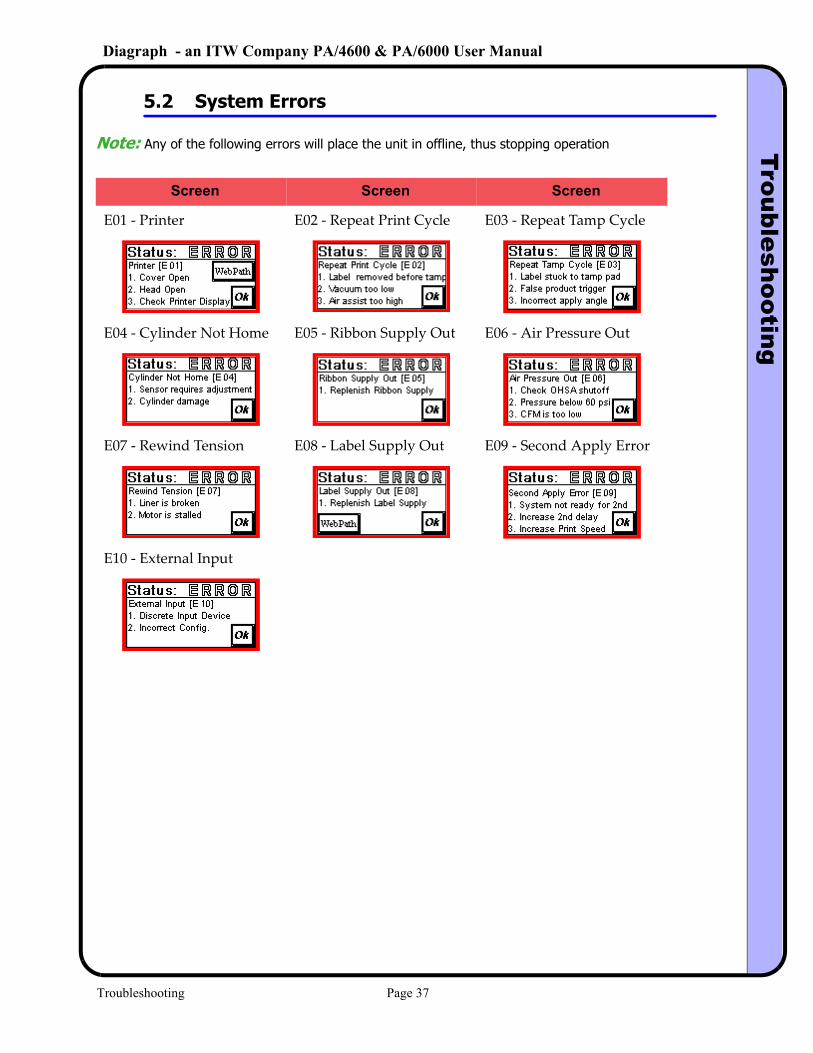
Note: Any of the following errors will place the unit in offline, thus stopping operation
Screen Screen Screen
E01 ‐ Printer E02 ‐ Repeat Print Cycle E03 ‐ Repeat Tamp Cycle
E04 ‐ Cylinder Not Home E05 ‐ Ribbon Supply Out E06 ‐ Air Pressure Out
E07 ‐ Rewind Tension E08 ‐ Label Supply Out E09 ‐ Second Apply Error
E10 ‐ External Input
Troubleshooting Page 37
Diagraph - an ITW Company PA/4600 & PA/6000 User ManualTroubleshooting
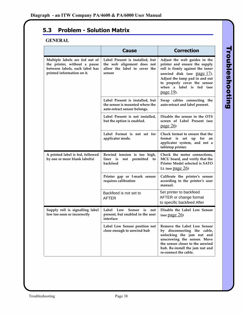
5.3 Problem - Solution Matrix
GENERAL
Problem Cause Correction
Multiple labels are fed out of the printer, without a pause between labels, each label has printed information on it.
Label Present is installed, but the web alignment does not allow the label to cover the sensor
Adjust the web guides in the printer and ensure the supply roll is firmly against the inner unwind disk (see page 17). Adjust the tamp pad in and out to properly cover the sensor when a label is fed (see page 19).
Label Present is installed, but the sensor is mounted where the auto‐retract sensor belongs.
Swap cables connecting the auto‐retract and label present.
Label Present is not installed, but the option is enabled.
Disable the sensor in the OTS screen of Label Present (see page 26)
Label Format is not set for applicator mode.
Check format to ensure that the format is set up for an applicator system, and not a tabletop printer.
A printed label is fed, followed by one or more blank label(s)
Rewind tension is too high, liner is not permitted to backfeed
Check the motor connections, MCU board, and verify that the Printer Model selected is SATO Lt. (see page 26)
Printer gap or I‐mark sensor requires calibration
Calibrate the printer’s sensor according to the printer’s user manual.
Supply roll is signalling label low too soon or incorrectly
Label Low Sensor is not present, but enabled in the user interface
Disable the Label Low Sensor (see page 26)
Label Low Sensor position not close enough to unwind hub
Remove the Label Low Sensor by disconnecting the cable, unlocking the jam nut and unscrewing the sensor. Move the sensor closer to the unwind hub. Re‐install the jam nut and re‐connect the cable.
Backfeed is not set to AFTER
Set printer to backfeedAFTER or change formatto specific backfeed After
Troubleshooting Page 38
Diagraph - an ITW Company PA/4600 & PA/6000 User ManualTroubleshooting
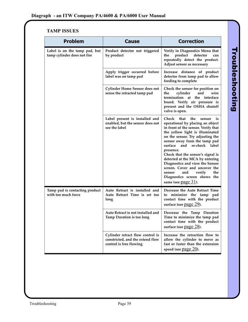
TAMP ISSUES
Problem Cause Correction
Label is on the tamp pad, but tamp cylinder does not fire
Product detector not triggered by product
Verify in Diagnostics Menu that the product detector can repeatedly detect the product. Adjust sensor as necessary
Apply trigger occurred before label was on tamp pad
Increase distance of product detector from tamp pad to allow feeding to complete
Cylinder Home Sensor does not sense the retracted tamp pad
Check the sensor for position on the cylinder and wire termination at the interface board. Verify air pressure is present and the OSHA shutoff valve is open.
Label present is installed and enabled, but the sensor does not see the label
Check that the sensor is operational by placing an object in front of the sensor. Verify that the yellow light is illuminated on the sensor. Try adjusting the sensor away from the tamp pad surface and re‐check label presence. Check that the sensor’s signal is detected at the MCA by entering Diagnostics and view the Sensor screen. Cover and uncover the sensor and verify the Diagnostics screen shows the same (see page 31).
Tamp pad is contacting product with too much force
Auto Retract is installed and Auto Retract Time is set too long
Decrease the Auto Retract Time to minimize the tamp pad contact time with the product surface (see page 29).
Auto Retract is not installed and Tamp Duration is too long
Decrease the Tamp Duration Time to minimize the tamp pad contact time with the product surface (see page 28).
Cylinder retract flow control is constricted, and the extend flow control is free flowing
Increase the retraction flow to allow the cylinder to move as fast or faster than the extension speed (see page 20).
Troubleshooting Page 39
Diagraph - an ITW Company PA/4600 & PA/6000 User ManualTroubleshooting
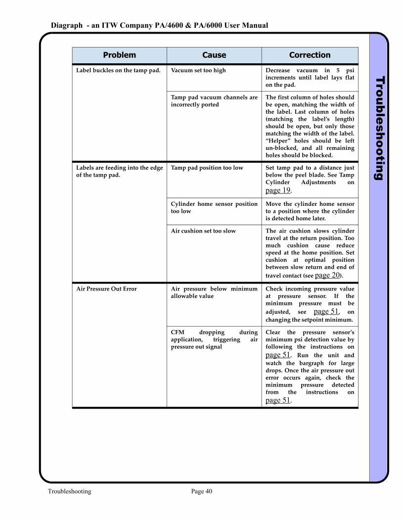
Label buckles on the tamp pad. Vacuum set too high Decrease vacuum in 5 psi increments until label lays flat on the pad.
Tamp pad vacuum channels are incorrectly ported
The first column of holes should be open, matching the width of the label. Last column of holes (matching the label’s length) should be open, but only those matching the width of the label. “Helper” holes should be left un‐blocked, and all remaining holes should be blocked.
Labels are feeding into the edge of the tamp pad.
Tamp pad position too low Set tamp pad to a distance just below the peel blade. See Tamp Cylinder Adjustments on page 19.
Cylinder home sensor position too low
Move the cylinder home sensor to a position where the cylinder is detected home later.
Air cushion set too slow The air cushion slows cylinder travel at the return position. Too much cushion cause reduce speed at the home position. Set cushion at optimal position between slow return and end of travel contact (see page 20).
Air Pressure Out Error Air pressure below minimum allowable value
Check incoming pressure value at pressure sensor. If the minimum pressure must be adjusted, see page 51, on changing the setpoint minimum.
CFM dropping during application, triggering air pressure out signal
Clear the pressure sensor’s minimum psi detection value by following the instructions on page 51. Run the unit and watch the bargraph for large drops. Once the air pressure out error occurs again, check the minimum pressure detected from the instructions on page 51.
Problem Cause Correction
Troubleshooting Page 40
Diagraph - an ITW Company PA/4600 & PA/6000 User ManualTroubleshooting
5.4 Catch Problems Before They Cause Downtime
Air Volume (CFM) ProblemsAir pressure is the main consideration when connecting a machine requiring compressed air, but air volume (measured in cubic feet per minute) is just as important for regular operation. An elec-trical analogy would be: the air pressure can be thought of as voltage and the air volume can be thought of as electrical current. If the voltage is too low, the light bulb will glow dimly. If the current is too low, the same problem will occur. The same is true for air pressure and volume. To determine if the line pressure is adequate, view the pressure reading on the sensor located on the air manifold. Measuring the air volume is slightly more difficult, but can be measured indi-rectly by viewing the bargraph on the pressure regulator while exercising the vacuum and tamp together. Using the electrical analogy, if the current (air volume) is too low, it will begin to effect the voltage (air pressure), which is seen as a drop. The air pressure sensor’s bargraph can be used as a fairly good indicator of a system “starving” for air. During operation, if the bargraph height fluctuates widely, around 30 psi or more than the set value, there could be an air volume problem. Identifying a low CFM problem early will avoid an unexpected shutdown of the system. Small air line diameters, kinked hoses, and undersized storage tank volume can be the culprit of air pressure problems due to low CFM.
Label Supply ProblemsAs fundamentally simple as a roll of labels would appear, there are a few key areas that can cause problems and these problems are sometimes falsely associated with the equipment and not the label. The typical symptoms may include labels not peeling, labels falling off of the tamp pad, and labels jamming inside the printer. The respective possible causes are: the diecut is too deep, the label adhesive is too aggressive, or the label roll has expired due to age. There are several simple tests to determine if any of these problems exist on a questionable roll of labels.Test for Incorrect Diecut:Using a felt-tipped permanent marker, color in the outline of the removed label, on the top (shiny, almost waxy) side of the liner. The marker will not easily transfer onto the liner, but use a circular drawing pattern along the edge to color it in. Turn over the liner and see if the marker bled through to the other side. If so, the diecut is too deep, and the adhesive from the label is bonding to the liner where there is no release silicone. This will make the label difficult to peel and could result in random labels not peeling with each print cycle. Test several labels as this may be a random issue; for example, every fourth or fifth label could exhibit the problem.Test for Adhesive Problems:Manually remove the label from the liner, and set it adhesive-side up on a flat surface. Ideally, the room temperature should be around 70 degrees fahrenheit, at a 50% relative humidity. Wait 10 minutes, and measure the end of the label curl to the surface. If the curl vertical height is more than 10% of label length, the adhesive is shrinking upon exposure to air, and it is forcing the label to curl beyond the point where the vacuum on the tamp pad can adequately hold the label in place.
Troubleshooting Page 41
Diagraph - an ITW Company PA/4600 & PA/6000 User ManualM
aintenance
6.0 Maintenance
6.1 Maintenance Schedule
6.2 Updating the System Firmware
From time to time, improvements to system performance, corrections to errors, or additional features and options may necessitate an upgrade to the system firmware. This is a simple process of using a software application named MTool2. This can be located on the Diagraph web site, under downloads. To perform a firmware upgrade, download the MTool2 and fill out the form to request an access license. Once the MTool2 application is installed, change the system baud rate to 115.2k, if the serial port is used. Start the MTool2 program and once the system’s param-eters are read, select the tab to download new firmware. This takes approximately one minute, and concludes by re-reading the parameters.
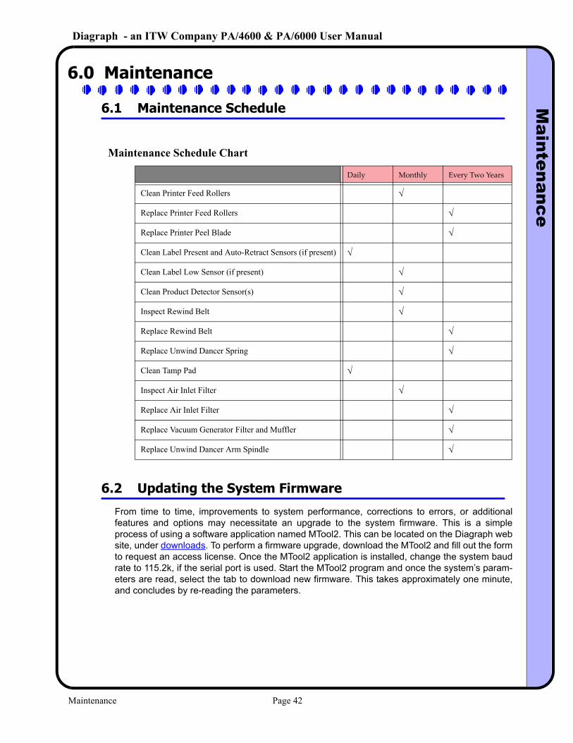
Maintenance Schedule Chart
Daily Monthly Every Two Years
Clean Printer Feed Rollers √
Replace Printer Feed Rollers √
Replace Printer Peel Blade √
Clean Label Present and Auto-Retract Sensors (if present) √
Clean Label Low Sensor (if present) √
Clean Product Detector Sensor(s) √
Inspect Rewind Belt √
Replace Rewind Belt √
Replace Unwind Dancer Spring √
Clean Tamp Pad √
Inspect Air Inlet Filter √
Replace Air Inlet Filter √
Replace Vacuum Generator Filter and Muffler √
Replace Unwind Dancer Arm Spindle √
Maintenance Page 42
Diagraph - an ITW Company PA/4600 & PA/6000 User ManualM
aintenance
6.3 Recommended Spare Parts List
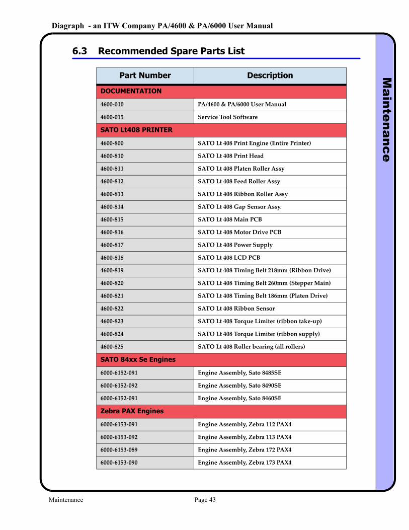
Part Number Description
DOCUMENTATION
4600‐010 PA/4600 & PA/6000 User Manual
4600‐015 Service Tool Software
SATO Lt408 PRINTER
4600‐800 SATO Lt 408 Print Engine (Entire Printer)
4600‐810 SATO Lt 408 Print Head
4600‐811 SATO Lt 408 Platen Roller Assy
4600‐812 SATO Lt 408 Feed Roller Assy
4600‐813 SATO Lt 408 Ribbon Roller Assy
4600‐814 SATO Lt 408 Gap Sensor Assy.
4600‐815 SATO Lt 408 Main PCB
4600‐816 SATO Lt 408 Motor Drive PCB
4600‐817 SATO Lt 408 Power Supply
4600‐818 SATO Lt 408 LCD PCB
4600‐819 SATO Lt 408 Timing Belt 218mm (Ribbon Drive)
4600‐820 SATO Lt 408 Timing Belt 260mm (Stepper Main)
4600‐821 SATO Lt 408 Timing Belt 186mm (Platen Drive)
4600‐822 SATO Lt 408 Ribbon Sensor
4600‐823 SATO Lt 408 Torque Limiter (ribbon take‐up)
4600‐824 SATO Lt 408 Torque Limiter (ribbon supply)
4600‐825 SATO Lt 408 Roller bearing (all rollers)
SATO 84xx Se Engines
6000‐6152‐091 Engine Assembly, Sato 8485SE
6000‐6152‐092 Engine Assembly, Sato 8490SE
6000‐6152‐091 Engine Assembly, Sato 8460SE
Zebra PAX Engines
6000‐6153‐091 Engine Assembly, Zebra 112 PAX4
6000‐6153‐092 Engine Assembly, Zebra 113 PAX4
6000‐6153‐089 Engine Assembly, Zebra 172 PAX4
6000‐6153‐090 Engine Assembly, Zebra 173 PAX4
Maintenance Page 43
Diagraph - an ITW Company PA/4600 & PA/6000 User ManualM
aintenance
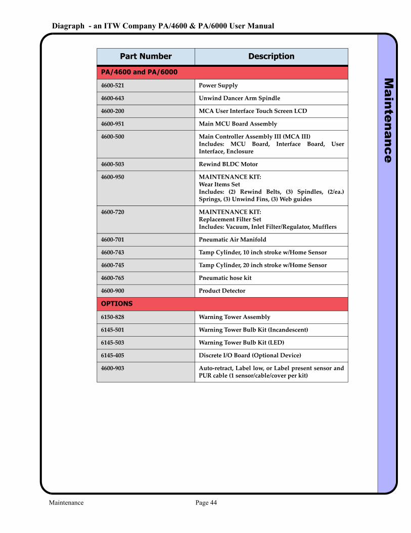
PA/4600 and PA/6000
4600‐521 Power Supply
4600‐643 Unwind Dancer Arm Spindle
4600‐200 MCA User Interface Touch Screen LCD
4600‐951 Main MCU Board Assembly
4600‐500 Main Controller Assembly III (MCA III)Includes: MCU Board, Interface Board, User Interface, Enclosure
4600‐503 Rewind BLDC Motor
4600‐950 MAINTENANCE KIT:Wear Items SetIncludes: (2) Rewind Belts, (3) Spindles, (2/ea.) Springs, (3) Unwind Fins, (3) Web guides
4600‐720 MAINTENANCE KIT:Replacement Filter SetIncludes: Vacuum, Inlet Filter/Regulator, Mufflers
4600‐701 Pneumatic Air Manifold
4600‐743 Tamp Cylinder, 10 inch stroke w/Home Sensor
4600‐745 Tamp Cylinder, 20 inch stroke w/Home Sensor
4600‐765 Pneumatic hose kit
4600‐900 Product Detector
OPTIONS
6150‐828 Warning Tower Assembly
6145‐501 Warning Tower Bulb Kit (Incandescent)
6145‐503 Warning Tower Bulb Kit (LED)
6145‐405 Discrete I/O Board (Optional Device)
4600‐903 Auto‐retract, Label low, or Label present sensor and PUR cable (1 sensor/cable/cover per kit)
Part Number Description
Maintenance Page 44
Diagraph - an ITW Company PA/4600 & PA/6000 User ManualM
aintenance
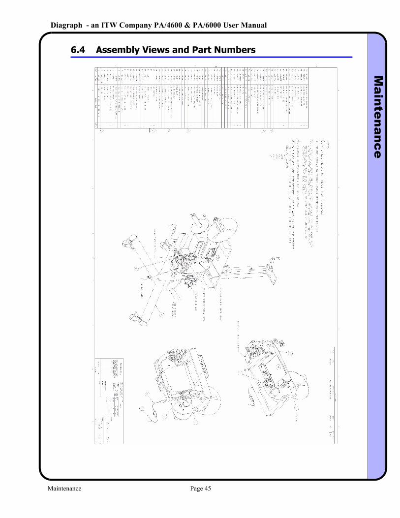
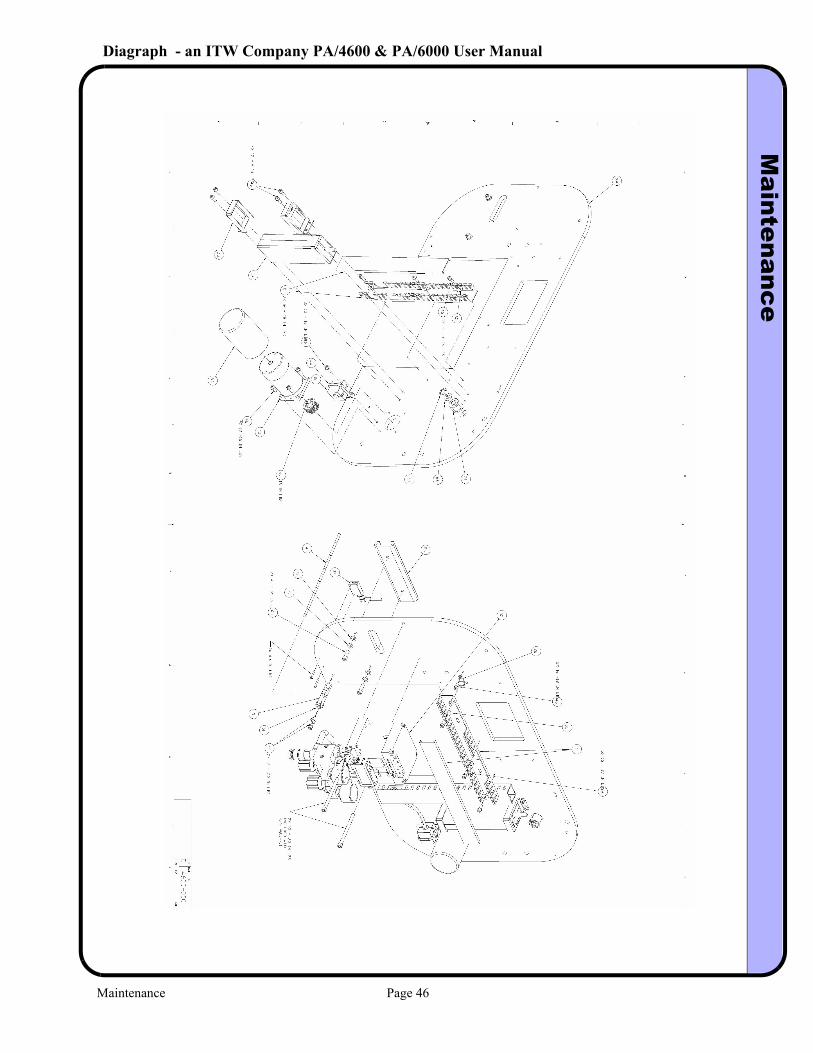
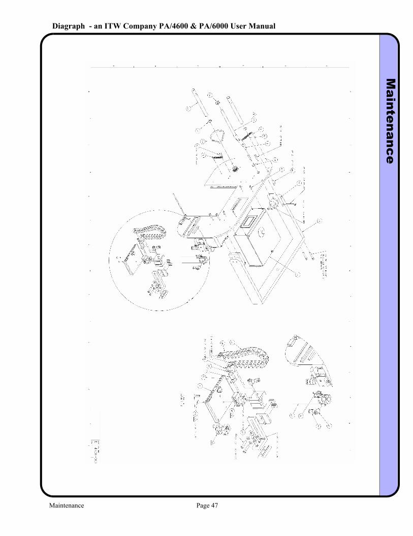
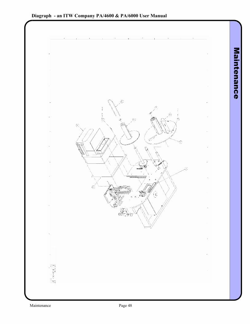
6.4 Assembly Views and Part Numbers
Maintenance Page 45
Diagraph - an ITW Company PA/4600 & PA/6000 User ManualM
aintenance
Maintenance Page 46
Diagraph - an ITW Company PA/4600 & PA/6000 User ManualM
aintenance
Maintenance Page 47
Diagraph - an ITW Company PA/4600 & PA/6000 User ManualM
aintenance
Maintenance Page 48
Diagraph - an ITW Company PA/4600 & PA/6000 User ManualC
onnection Port Inform
ation
7.0 Connection Port Information
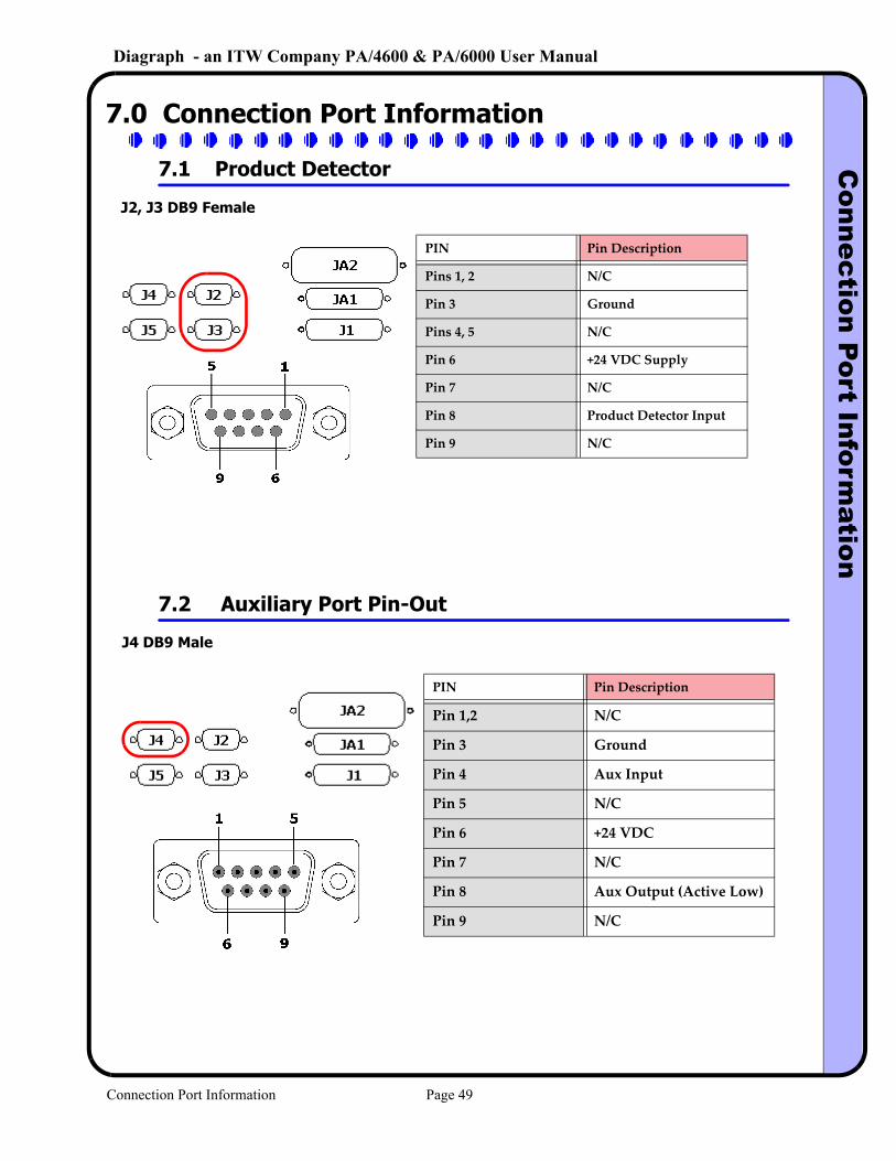
7.1 Product Detector
J2, J3 DB9 Female
PIN Pin Description
Pins 1, 2 N/C
Pin 3 Ground
Pins 4, 5 N/C
Pin 6 +24 VDC Supply
Pin 7 N/C
Pin 8 Product Detector Input
Pin 9 N/C
7.2 Auxiliary Port Pin-Out
J4 DB9 Male
PIN Pin Description
Pin 1,2 N/C
Pin 3 Ground
Pin 4 Aux Input
Pin 5 N/C
Pin 6 +24 VDC
Pin 7 N/C
Pin 8 Aux Output (Active Low)
Pin 9 N/C
Connection Port Information Page 49
Diagraph - an ITW Company PA/4600 & PA/6000 User ManualC
onnection Port Inform
ation
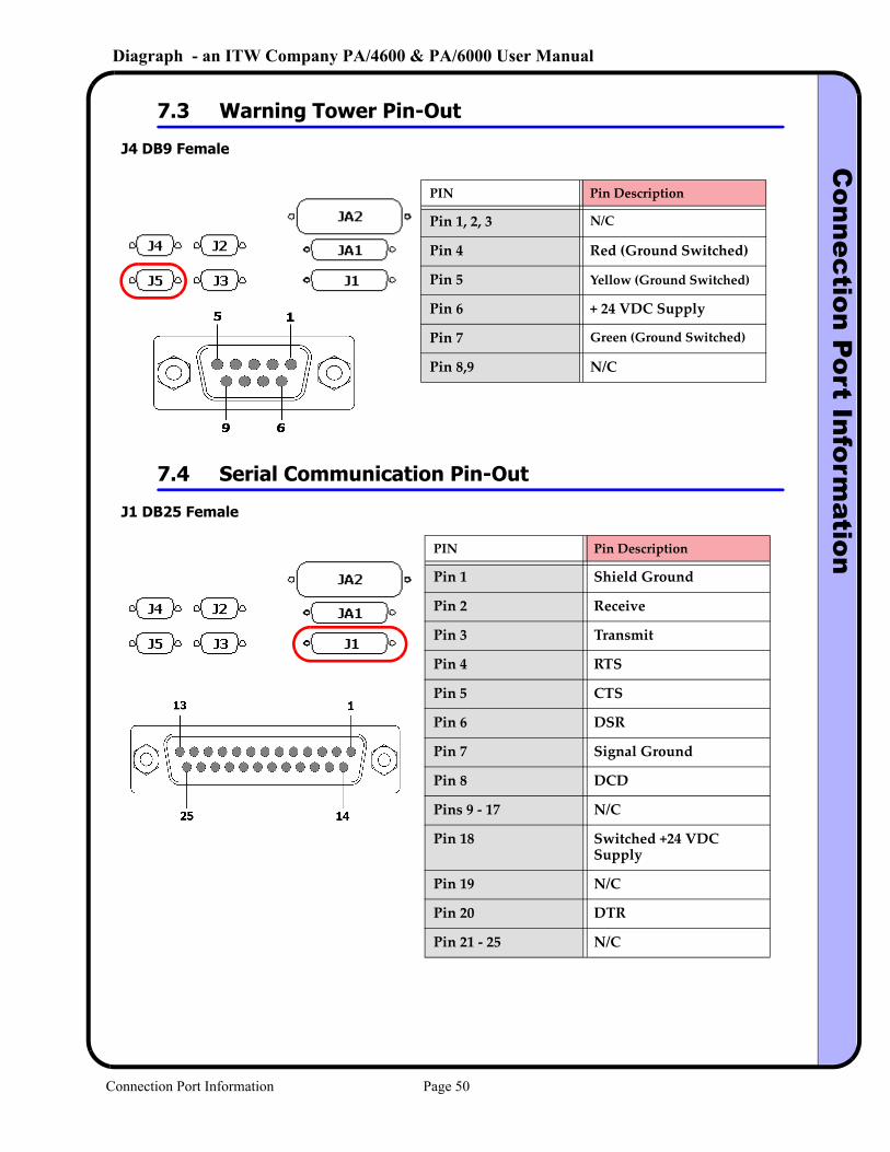
7.3 Warning Tower Pin-Out
J4 DB9 Female
PIN Pin Description
Pin 1, 2, 3 N/C
Pin 4 Red (Ground Switched)
Pin 5 Yellow (Ground Switched)
Pin 6 + 24 VDC Supply
Pin 7 Green (Ground Switched)
Pin 8,9 N/C
7.4 Serial Communication Pin-Out
J1 DB25 Female
PIN Pin Description
Pin 1 Shield Ground
Pin 2 Receive
Pin 3 Transmit
Pin 4 RTS
Pin 5 CTS
Pin 6 DSR
Pin 7 Signal Ground
Pin 8 DCD
Pins 9 ‐ 17 N/C
Pin 18 Switched +24 VDC Supply
Pin 19 N/C
Pin 20 DTR
Pin 21 ‐ 25 N/C
Connection Port Information Page 50
Diagraph - an ITW Company PA/4600 & PA/6000 User ManualP
ressure Sensor A
djustment
8.0 Pressure Sensor Adjustment
8.1 Pressure Sensor Setup
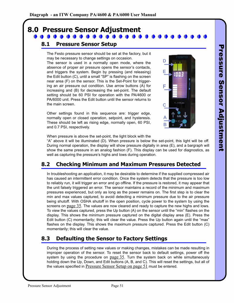
The Festo pressure sensor should be set at the factory, but it may be necessary to change settings on occasion. The sensor is used in a normally open mode, where the absence of proper air pressure opens the sensor’s contacts, and triggers the system. Begin by pressing (and releasing) the Edit button (C), until a small “SP” is flashing on the screen near area (F) on the sensor. This is the Set-Point for trigger-ing an air pressure out condition. Use arrow buttons (A) for increasing and (B) for decreasing the set-point. The default setting should be 60 PSI for operation with the PA/4600 or PA/6000 unit. Press the Edit button until the sensor returns to the main screen.
Other settings found in this sequence are: trigger edge, normally open or closed operation, setpoint, and hysteresis. These should be left as rising edge, normally open, 60 PSI, and 0.7 PSI, respectively.
When pressure is above the set-point, the light block with the “A” above it will be illuminated (D). When pressure is below the set-point, this light will be off. During normal operation, the display will show pressure digitally in area (E), and a bargraph will show the same pressure in an analog fashion (F). This display can be used for diagnostics, as well as capturing the pressure’s highs and lows during operation.
8.2 Checking Minimum and Maximum Pressures Detected
In troubleshooting an application, it may be desirable to determine if the supplied compressed air has caused an intermittent error condition. Once the system detects that the pressure is too low to reliably run, it will trigger an error and go offline. If the pressure is restored, it may appear that the unit falsely triggered an error. The sensor maintains a record of the minimum and maximum pressures experienced, but only as long as the power remains on. The first step is to clear the min and max values captured, to avoid detecting a minimum pressure due to the air pressure being shutoff. With OSHA shutoff in the open position, cycle power to the system by using the screens on page 35. The values are now cleared and ready to capture the new highs and lows. To view the values captured, press the Up button (A) on the sensor until the “min” flashes on the display. This shows the minimum pressure captured on the digital display area (E). Press the Edit button (C) momentarily; this will clear the value. Press the Up button again until the “max” flashes on the display. This shows the maximum pressure captured. Press the Edit button (C) momentarily; this will clear the value.
8.3 Defaulting the Sensor to Factory Settings
During the process of setting new values or making changes, mistakes can be made resulting in improper operation of the sensor. To reset the sensor back to default settings, power off the system by using the procedure on page 35. Turn the system back on while simultaneously holding down the Up, Down, and Edit buttons (A, B, and C). This will reset the settings, but all of the values specified in Pressure Sensor Setup on page 51 must be entered.
D
E
AB
C
F
Pressure Sensor Adjustment Page 51
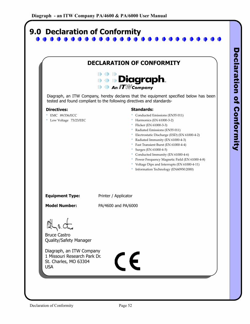
Diagraph - an ITW Company PA/4600 & PA/6000 User ManualD
eclaration of Conform
ity
9.0 Declaration of Conformity
DECLARATION OF CONFORMITY
Diagraph, an ITW Company, hereby declares that the equipment specified below has been tested and found compliant to the following directives and standards-
Directives:• EMC 89/336/ECC• Low Voltage 73/23/EEC
Standards:• Conducted Emissions (EN55 011)• Harmonics (EN 61000‐3‐2)• Flicker (EN 61000‐3‐3)• Radiated Emissions (EN55 011)• Electrostatic Discharge (ESD) (EN 61000‐4‐2)• Radiated Immunity (EN 61000‐4‐3)• Fast Transient Burst (EN 61000‐4‐4)• Surges (EN 61000‐4‐5)• Conducted Immunity (EN 61000‐4‐6)• Power Frequency Magnetic Field (EN 61000‐4‐8)• Voltage Dips and Interrupts (EN 61000‐4‐11)• Information Technology (EN60950:2000)
Equipment Type: Printer / Applicator
Model Number: PA/4600 and PA/6000
Bruce CastroQuality/Safety Manager
Diagraph, an ITW Company1 Missouri Research Park Dr.St. Charles, MO 63304USA
Declaration of Conformity Page 52


