88
P/ACE™ MDQ Plus Capillary Electrophoresis System System Maintenance Guide RUO-IDV-05-4904-A January 2019

P/ACE™ MDQ Plus Capillary Electrophoresis System
System Maintenance Guide
RUO-IDV-05-4904-AJanuary 2019

This document is provided to customers who have purchased SCIEX equipment to use in the operation of such SCIEX equipment. This document is copyright protected and any reproduction of this document or any part of this document is strictly prohibited, except as SCIEX may authorize in writing.Software that may be described in this document is furnished under a license agreement. It is against the law to copy, modify, or distribute the software on any medium, except as specifically allowed in the license agreement. Furthermore, the license agreement may prohibit the software from being disassembled, reverse engineered, or decompiled for any purpose. Warranties are as stated therein.Portions of this document may make reference to other manufacturers and/or their products, which may contain parts whose names are registered as trademarks and/or function as trademarks of their respective owners. Any such use is intended only to designate those manufacturers' products as supplied by SCIEX for incorporation into its equipment and does not imply any right and/or license to use or permit others to use such manufacturers' and/or their product names as trademarks.SCIEX warranties are limited to those express warranties provided at the time of sale or license of its products and are SCIEX’s sole and exclusive representations, warranties, and obligations. SCIEX makes no other warranty of any kind whatsoever, expressed or implied, including without limitation, warranties of merchantability or fitness for a particular purpose, whether arising from a statute or otherwise in law or from a course of dealing or usage of trade, all of which are expressly disclaimed, and assumes no responsibility or contingent liability, including indirect or consequential damages, for any use by the purchaser or for any adverse circumstances arising therefrom.For Research Use Only. Not for use in Diagnostic Procedures.AB Sciex is operating as SCIEX.The trademarks mentioned herein are the property of AB Sciex Pte. Ltd. or their respective owners.AB SCIEX™ is being used under license.© 2019 AB Sciex
P/
2
ACE™ MDQ Plus Capillary Electrophoresis System System Maintenance Guide
/ 88 RUO-IDV-05-4904-A | B54955AB
AB Sciex LLC500 Old Connecticut PathFramingham, Massachusetts 01701USA
Contents
Chapter 1 Installation Procedures . . . . . . . . . . . . . . . . . . . . . . . . . . . . . . . . . . . . . . 5Install the UV or PDA Detector . . . . . . . . . . . . . . . . . . . . . . . . . . . . . . . . . . . . . . . 6Install Wavelength Filters for the UV Detector . . . . . . . . . . . . . . . . . . . . . . . . . . . 9Calibrate the PDA Detector . . . . . . . . . . . . . . . . . . . . . . . . . . . . . . . . . . . . . . . . . 14Install the LIF Detector. . . . . . . . . . . . . . . . . . . . . . . . . . . . . . . . . . . . . . . . . . . . . 15
Installation Requirements . . . . . . . . . . . . . . . . . . . . . . . . . . . . . . . . . . . . . . . . . 16Install the LIF Detector Filters . . . . . . . . . . . . . . . . . . . . . . . . . . . . . . . . . . . . . 16Install the LIF Detector in the P/ACE™ MDQ Plus Instrument . . . . . . . . . . . 18Connect the Probe to the Clamp Bar. . . . . . . . . . . . . . . . . . . . . . . . . . . . . . . . . 19
Calibrate the LIF Detector . . . . . . . . . . . . . . . . . . . . . . . . . . . . . . . . . . . . . . . . . . 20Troubleshoot the LIF Detector Calibration. . . . . . . . . . . . . . . . . . . . . . . . . . . . 23
Install the Capillary Cartridge. . . . . . . . . . . . . . . . . . . . . . . . . . . . . . . . . . . . . . . . 24Rebuild a Capillary Cartridge . . . . . . . . . . . . . . . . . . . . . . . . . . . . . . . . . . . . . . 24Install the Capillary Cartridge into the P/ACE™ MDQ Plus Instrument . . . . . 42
Install the Universal Vials and Caps. . . . . . . . . . . . . . . . . . . . . . . . . . . . . . . . . . . 44Fill the Universal Vials . . . . . . . . . . . . . . . . . . . . . . . . . . . . . . . . . . . . . . . . . . . 44Fill the Micro Vials . . . . . . . . . . . . . . . . . . . . . . . . . . . . . . . . . . . . . . . . . . . . . . 45
Chapter 2 Maintenance Procedures . . . . . . . . . . . . . . . . . . . . . . . . . . . . . . . . . . . . 47Clean the Ejecting Levers, Electrodes, and Interface Block. . . . . . . . . . . . . . . . . 48
Remove the Ejecting Levers . . . . . . . . . . . . . . . . . . . . . . . . . . . . . . . . . . . . . . . 49Remove the Electrodes . . . . . . . . . . . . . . . . . . . . . . . . . . . . . . . . . . . . . . . . . . . 50Replace the Electrodes in the Interface Block . . . . . . . . . . . . . . . . . . . . . . . . . 52Replace the Ejecting Levers . . . . . . . . . . . . . . . . . . . . . . . . . . . . . . . . . . . . . . . 52
Refill the Capillary Coolant . . . . . . . . . . . . . . . . . . . . . . . . . . . . . . . . . . . . . . . . . 53 Clean the Fiber Optic Cable (UV and PDA Detectors) . . . . . . . . . . . . . . . . . . . . 54Replace the Deuterium Lamp . . . . . . . . . . . . . . . . . . . . . . . . . . . . . . . . . . . . . . . . 56Procedures for Instrument Care . . . . . . . . . . . . . . . . . . . . . . . . . . . . . . . . . . . . . . 62
Replace the Quad Rings . . . . . . . . . . . . . . . . . . . . . . . . . . . . . . . . . . . . . . . . . . 62Replace the Fuses . . . . . . . . . . . . . . . . . . . . . . . . . . . . . . . . . . . . . . . . . . . . . . . 63
Procedures for LIF Detector Care and Maintenance . . . . . . . . . . . . . . . . . . . . . . 65Inspect the LIF . . . . . . . . . . . . . . . . . . . . . . . . . . . . . . . . . . . . . . . . . . . . . . . . . 65Clean the LIF Modules . . . . . . . . . . . . . . . . . . . . . . . . . . . . . . . . . . . . . . . . . . . 65Store the LIF Probe . . . . . . . . . . . . . . . . . . . . . . . . . . . . . . . . . . . . . . . . . . . . . . 65
Chapter 3 Connect the System to a Mass Spectrometer . . . . . . . . . . . . . . . . . . . 67About CE-MS Mode. . . . . . . . . . . . . . . . . . . . . . . . . . . . . . . . . . . . . . . . . . . . . . . 67Install the Capillary in the Standard Cartridge . . . . . . . . . . . . . . . . . . . . . . . . . . . 68Install the Capillary in the EDA-Only Cartridge . . . . . . . . . . . . . . . . . . . . . . . . . 71
System Maintenance Guide P/ACE™ MDQ Plus Capillary Electrophoresis System
RUO-IDV-05-4904-A | B54955AB 3 / 88

Install the Ground Connection. . . . . . . . . . . . . . . . . . . . . . . . . . . . . . . . . . . . . . . .73Chapter A Evaluating UV Filters . . . . . . . . . . . . . . . . . . . . . . . . . . . . . . . . . . . . . .75
Overview . . . . . . . . . . . . . . . . . . . . . . . . . . . . . . . . . . . . . . . . . . . . . . . . . . . . . . . .75Chapter B Performance Tests for the LIF Detector . . . . . . . . . . . . . . . . . . . . . . .79
Relative Fluorescent Units (RFU) . . . . . . . . . . . . . . . . . . . . . . . . . . . . . . . . . . . . .79Calibration Correction Factor (CCF). . . . . . . . . . . . . . . . . . . . . . . . . . . . . . . . . . .79Applying the CCF . . . . . . . . . . . . . . . . . . . . . . . . . . . . . . . . . . . . . . . . . . . . . . . . .80
Automatic Calibration . . . . . . . . . . . . . . . . . . . . . . . . . . . . . . . . . . . . . . . . . . . .80Calibration Method . . . . . . . . . . . . . . . . . . . . . . . . . . . . . . . . . . . . . . . . . . . . . .81Calibration Results . . . . . . . . . . . . . . . . . . . . . . . . . . . . . . . . . . . . . . . . . . . . . . .82
Non-fluorescent Solutions . . . . . . . . . . . . . . . . . . . . . . . . . . . . . . . . . . . . . . . . . . .82LIF Calibration for Other Capillaries . . . . . . . . . . . . . . . . . . . . . . . . . . . . . . . . . .83LIF Calibration for Different Fluorescent Solutions . . . . . . . . . . . . . . . . . . . . . . .83Standard System Performance Test . . . . . . . . . . . . . . . . . . . . . . . . . . . . . . . . . . . .84
Calibration Method . . . . . . . . . . . . . . . . . . . . . . . . . . . . . . . . . . . . . . . . . . . . . .84Calibration Results . . . . . . . . . . . . . . . . . . . . . . . . . . . . . . . . . . . . . . . . . . . . . . .85
Troubleshooting. . . . . . . . . . . . . . . . . . . . . . . . . . . . . . . . . . . . . . . . . . . . . . . . . . .86Contact Us . . . . . . . . . . . . . . . . . . . . . . . . . . . . . . . . . . . . . . . . . . . . . . . . . . . . . . . . .87
Customer Training . . . . . . . . . . . . . . . . . . . . . . . . . . . . . . . . . . . . . . . . . . . . . . . . .87Online Learning Center . . . . . . . . . . . . . . . . . . . . . . . . . . . . . . . . . . . . . . . . . . . . .87SCIEX Support . . . . . . . . . . . . . . . . . . . . . . . . . . . . . . . . . . . . . . . . . . . . . . . . . . .87CyberSecurity . . . . . . . . . . . . . . . . . . . . . . . . . . . . . . . . . . . . . . . . . . . . . . . . . . . .87Documentation. . . . . . . . . . . . . . . . . . . . . . . . . . . . . . . . . . . . . . . . . . . . . . . . . . . .88
P/ACE™ MDQ Plus Capillary Electrophoresis System System Maintenance Guide
4 / 88 RUO-IDV-05-4904-A | B54955AB

CHAPTER 1
Installation Procedures
CAUTIONPrior to using the system, refer to the safety content in the System Overview Guide for detailed information on the safe use and operation of the system.
This chapter contains the following installation procedures for the SCIEX P/ACE™ MDQ Plus capillary electrophoresis system. Begin by installing the detector, and then continue to remaining items.
• Install the UV or PDA Detector on page 6 • Install Wavelength Filters for the UV Detector on page 9 • Calibrate the PDA Detector on page 14 • Install the LIF Detector on page 15 • Install the Capillary Cartridge on page 24 • Install the Universal Vials and Caps on page 44
WARNINGDisconnect the power before any instrument disassembly. Failure to do so can cause electrical shock or other injury.
WARNINGMaintenance or repair procedures not specifically described in this guide present a risk of electrical shock or injury. Refer additional servicing to SCIEX.
WARNINGDo not attempt to defeat any of the instrument interlocks or safety mechanisms.
System Maintenance Guide P/ACE™ MDQ Plus Capillary Electrophoresis System
RUO-IDV-05-4904-A | B54955AB 5 / 88
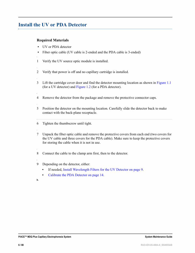
Install the UV or PDA Detector
Required Materials • UV or PDA detector • Fiber optic cable (UV cable is 2-ended and the PDA cable is 3-ended)
1 Verify the UV source optic module is installed.
2 Verify that power is off and no capillary cartridge is installed.
3 Lift the cartridge cover door and find the detector mounting location as shown in Figure 1.1 (for a UV detector) and Figure 1.2 (for a PDA detector).
4 Remove the detector from the package and remove the protective connector caps.
5 Position the detector on the mounting location. Carefully slide the detector back to make contact with the back-plane receptacle.
6 Tighten the thumbscrew until tight.
7 Unpack the fiber optic cable and remove the protective covers from each end (two covers for the UV cable and three covers for the PDA cable). Make sure to keep the protective covers for storing the cable when it is not in use.
8 Connect the cable to the clamp arm first, then to the detector.
9 Depending on the detector, either: • If needed, Install Wavelength Filters for the UV Detector on page 9. • Calibrate the PDA Detector on page 14.
P/ACE™ MDQ Plus Capillary Electrophoresis System System Maintenance Guide
6 / 88 RUO-IDV-05-4904-A | B54955AB

Figure 1.1 P/ACE™ MDQ Plus Instrument–Front View With UV Detector Installed
1. Outer Door Cover2. UV Detector3. Two-ended Fiber Optic Cable
4. Clamp Bar5. Capillary Cartridge6. Interface Block
System Maintenance Guide P/ACE™ MDQ Plus Capillary Electrophoresis System
RUO-IDV-05-4904-A | B54955AB 7 / 88
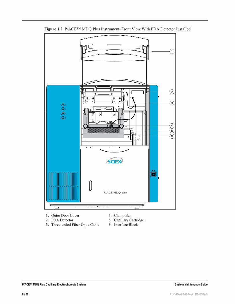
Figure 1.2 P/ACE™ MDQ Plus Instrument–Front View With PDA Detector Installed
1. Outer Door Cover2. PDA Detector3. Three-ended Fiber Optic Cable
4. Clamp Bar5. Capillary Cartridge6. Interface Block
P/ACE™ MDQ Plus Capillary Electrophoresis System System Maintenance Guide
8 / 88 RUO-IDV-05-4904-A | B54955AB

Install Wavelength Filters for the UV Detector
The P/ACE™ MDQ Plus system includes 200 nm, 214 nm, 230 nm, and 254 nm filters by default. The following section is for reference, if a different filter is required for your application.
Required Materials • Filters • Latex gloves
• Small forceps
1 Using the Direct Control window, move the trays to the load position.
2 Lift the outer door and then the cartridge cover door. The cartridge cover door is to the left of the UV detector as shown in Figure 1.1.
3 Loosen the two thumbscrews and lift the clamp bar.
4 Remove the capillary cartridge from the interface block.
5 Turn the system power off.
6 Loosen the two thumbscrews and remove the optics source assembly. Put the assembly on a clean work surface. The optics source assembly is located right behind the interface block and has a horizontal bar handle as shown in Figure 1.3.
7 Remove the filter wheel access cover and rotate the filter wheel until the correct filter is visible (Figure 1.3).
System Maintenance Guide P/ACE™ MDQ Plus Capillary Electrophoresis System
RUO-IDV-05-4904-A | B54955AB 9 / 88

Figure 1.3 Remove the Filter Wheel Access Cover
8 Put on latex gloves and use small forceps to remove the filters from the filter wheel. Touching the optical surfaces of the filters without gloves leaves skin oil that can cause improper filter performance.
9 Inspect each filter for a burned spot. Replace any filters that appear damaged.The filters are affected by heat and time. It is good practice to periodically check filter performance with a spectrometer or to replace the filters.
10 Insert the new filter with the reflective side facing inward (Figure 1.4).
1. Open cover at the indicated point2. Access Cover3. Thumbscrews (2), one on each side
P/ACE™ MDQ Plus Capillary Electrophoresis System System Maintenance Guide
10 / 88 RUO-IDV-05-4904-A | B54955AB

Figure 1.4 Install a New Filter
11 When all filters have been inspected or replaced, reinstall the filter wheel access cover.
12 Place the optics source assembly in the mounting location. Align the two upper guide pins and tighten the two thumbscrews.
13 Reinstall the capillary cartridge in the interface block.
14 Lower the insertion bar and tighten the two thumbscrews.
15 Close the cartridge cover door.
16 Turn the system power on and start the P/ACE™ MDQ Plus software.
17 Click Tools > Enterprise Login.
18 Right-click an instrument icon and click Configure > Instrument. (System Administration mode must be enabled, and the user must have instrument administration privileges to configure the instrument.)
System Maintenance Guide P/ACE™ MDQ Plus Capillary Electrophoresis System
RUO-IDV-05-4904-A | B54955AB 11 / 88

19 Click Configure on the instrument Configuration dialog.The P/ACE MDQ plus Configuration dialog appears (Figure 1.5).
Figure 1.5 P/ACE™ MDQ Plus Configuration Dialog
20 Click the green arrow to move the selected detector icon from Available modules in the left pane to Configured modules in the right pane.
21 Double-click the icon in the Configured modules list to open the P/ACE MDQ plus System Instrument Configuration dialog (Figure 1.6).
Figure 1.6 P/ACE™ MDQ Plus System Instrument Configuration Dialogan
P/ACE™ MDQ Plus Capillary Electrophoresis System System Maintenance Guide
12 / 88 RUO-IDV-05-4904-A | B54955AB

22 In the Filter area of the dialog, type the wavelength for each of the installed filters and then click OK to save the settings and close the dialog.
Figure 1.7 Filter Area Detail
System Maintenance Guide P/ACE™ MDQ Plus Capillary Electrophoresis System
RUO-IDV-05-4904-A | B54955AB 13 / 88

Calibrate the PDA Detector
The PDA detector must be calibrated following installation, after you change the lamp or other optical components, and when required as part of maintenance.
After the OPCAL cartridge is installed, calibrate the PDA detector as follows:
1 From the main menu, open an instrument configured with a PDA detector.
2 From the Control menu, click Direct Control. The Direct Control window appears.
Figure 1.8 PDA Detector–Direct Control Window
P/ACE™ MDQ Plus Capillary Electrophoresis System System Maintenance Guide
14 / 88 RUO-IDV-05-4904-A | B54955AB

3 Click the rainbow above the lamp. The PDA Detector Parameters dialog appears.
Figure 1.9 PDA Detector Parameters Dialog
4 Click Calibrate to start the calibration sequence. The calibration requires approximately two minutes. Do not try to access the instrument during the calibration process.
Install the LIF Detector
WARNINGIt is not safe to operate the solid-state laser module on any system other than the P/ACE™ MDQ Plus capillary electrophoresis system. The 488 nm solid-state laser draws more current than the interconnect module, previously used with the 488 nm argon ion laser, and will damage older CE models. The new CE models (2009 and after) include a higher-rated wiring harness to safely operate with the increased current.
Before installing the solid-state laser, close the 32 Karat software.
System Maintenance Guide P/ACE™ MDQ Plus Capillary Electrophoresis System
RUO-IDV-05-4904-A | B54955AB 15 / 88

WARNINGTo prevent a possible shock hazard, power down the instrument before continuing with component installation.
Installation RequirementsA SCIEX FSE must complete the initial installation of the 488 nm solid-state laser. This procedure includes proper laser configuration, installation of the updated wiring harness, setup of the LIF detector (if necessary), and verification of operation including system safety features.
Install the Solid-State Laser Module
WARNINGTo prevent a possible shock hazard, power down the instrument before continuing with component installation.
If currently installed, remove the UV or PDA detector module from the P/ACE™ MDQ Plus instrument’s upper-right corner. Insert the solid-state laser module and secure by finger tightening the thumbscrews at the front of the module.
Install the LIF Detector FiltersBefore you install the LIF detector module, install the filters and filter housing.
The filters installed in channel 1 have a 488 nm rejection filter and a 520 nm emission filter. To use channel 2 requires a change to the detector. Contact SCIEX for assistance setting up and using channel 2.
The filter housing sits in the right side of the LIF detector and has two filter holders, one for each detector channel (Figure 1.10). You can use one or more filters in each filter holder, depending on the application and the width of the filter. Typical operation is with two filters: one rejection filter and one emission filter. The rejection filter prevents scattered laser light from passing into the detector. The emission filter is a band-pass filter that allows only the light at a selected wavelength to pass into the detector.
Depending on the application and laser, you can use any standard 0.5 inch diameter filters with wavelengths between of 350 nm to 750 nm. The total thickness of the filters cannot exceed 0.350 inches.
P/ACE™ MDQ Plus Capillary Electrophoresis System System Maintenance Guide
16 / 88 RUO-IDV-05-4904-A | B54955AB
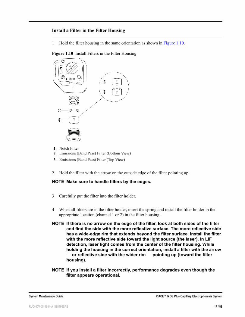
Install a Filter in the Filter Housing
1 Hold the filter housing in the same orientation as shown in Figure 1.10.
Figure 1.10 Install Filters in the Filter Housing
2 Hold the filter with the arrow on the outside edge of the filter pointing up.
NOTE Make sure to handle filters by the edges.
3 Carefully put the filter into the filter holder.
4 When all filters are in the filter holder, insert the spring and install the filter holder in the appropriate location (channel 1 or 2) in the filter housing.
NOTE If there is no arrow on the edge of the filter, look at both sides of the filter and find the side with the more reflective surface. The more reflective side has a wide-edge rim that extends beyond the filter surface. Install the filter with the more reflective side toward the light source (the laser). In LIF detection, laser light comes from the center of the filter housing. While holding the housing in the correct orientation, install a filter with the arrow — or reflective side with the wider rim — pointing up (toward the filter housing).
NOTE If you install a filter incorrectly, performance degrades even though the filter appears operational.
1. Notch Filter2. Emissions (Band Pass) Filter (Bottom View)3. Emissions (Band Pass) Filter (Top View)
System Maintenance Guide P/ACE™ MDQ Plus Capillary Electrophoresis System
RUO-IDV-05-4904-A | B54955AB 17 / 88

Install the Filter Housing in the DetectorInsert the filter housing into the opening in the right side of the detector (Figure 1.11). Make sure the keyed corner of the filter housing lines up with the keyed corner of the detector module. The housing is designed so it only fits in the opening in the orientation shown in the following figure. Refer to Figure 1.11.
After you change filters, allow the system to stabilize for 15 minutes before use.
Figure 1.11 Install the Filter Housing
Install the LIF Detector in the P/ACE™ MDQ Plus Instrument
WARNINGTo prevent a possible shock hazard, power down the P/ACE™ MDQ Plus instrument before continuing with component installation.
Before installing the LIF detector, remove the UV source optics module by loosening the knobs at the sides of the interface block. Remove the module using the handle.
P/ACE™ MDQ Plus Capillary Electrophoresis System System Maintenance Guide
18 / 88 RUO-IDV-05-4904-A | B54955AB

Connect the LIF detector to the P/ACE™ MDQ Plus instrument. Keep the two female connectors on the LIF detector level with the two male connectors found on the instrument. Lock the detector module in position by fastening the captive screws until finger-tight.
Connect the Probe to the Clamp BarIMPORTANT Be sure to install the LIF cartridge in the instrument and secure the
clamp bar before connecting the probe.
To connect the probe to the LIF cartridge, align the two pins on the left side of the probe and probe body to the two pin holes and the probe hole in the clamp bar. Squeeze the probe to open its jaws and carefully attach the probe to the clamp bar (Figure 1.12).
When not in use, install the probe in the probe holder on the 488 nm laser module. This provides mechanical protection for the probe and shields it from dust and other particles.
Figure 1.12 Connect the Probe to the LIF Cartridge
System Maintenance Guide P/ACE™ MDQ Plus Capillary Electrophoresis System
RUO-IDV-05-4904-A | B54955AB 19 / 88

Calibrate the LIF Detector
LIF detector calibration allows for normalization of the signal generated by an analyte relative to a known concentration of sodium fluorescein. Perform calibration after installation of a new capillary or after changing a detector or cartridge.
Required Materials • LIF Performance Test mix (PN 726022) • Double deionized water (DDI H2O)
NOTE System Administration must be enabled, and the user must have instrument administration privileges. From the Enterprise window, click Tools > System Administration to enable System Administration mode.
1 Right-click the instrument icon and click Configure Instrument.
2 Click Configure in the instrument Configuration window. The 32 Karat Software Configuration dialog appears.
3 Double-click the detector icon in the right pane of the P/ACE MDQ plus Configuration dialog.
4 Click LIF Calibration Wizard in the P/ACE MDQ plus System Instrument Configuration dialog.
5 Click Auto, then click Next to continue (Figure 1.13).
P/ACE™ MDQ Plus Capillary Electrophoresis System System Maintenance Guide
20 / 88 RUO-IDV-05-4904-A | B54955AB

Figure 1.13 Calibration Wizard–Step 1
6 Enter the target RFU value and capillary dimensions. Refer to the appropriate application guide for a recommended target RFU value. For example, the target value for an N-CHO-coated capillary is 7, not 35 as shown in Figure 1.14. Click Next.
Figure 1.14 Calibration Wizard–Step 2
System Maintenance Guide P/ACE™ MDQ Plus Capillary Electrophoresis System
RUO-IDV-05-4904-A | B54955AB 21 / 88

7 Fill the reagents into the buffer vials and put the buffer vials in the following positions of the inlet buffer tray: • A1: DDI H2O • B1: LIF Performance Test Mixture
8 Click Next to perform the automatic calibration (Figure 1.15).
NOTE The wizard displays buffer in position A1. Only use buffer for a system performance test when the installed capillary is bare fused-silica. For coated capillaries, follow the application guide instructions for test mix calibration or substitute water for buffer.
Figure 1.15 Calibration Wizard–Step 3
9 Click Accept when the calibration completes (Figure 1.16).
Figure 1.16 Calibration Wizard–Step 4
P/ACE™ MDQ Plus Capillary Electrophoresis System System Maintenance Guide
22 / 88 RUO-IDV-05-4904-A | B54955AB

Troubleshoot the LIF Detector Calibration
CCF < 1CCF values less than one indicate the system is working more efficiently than expected. Verify the following:
• Make sure the appropriate dimensions of the capillary are used. • Verify laser output for the laser in use on the P/ACE™ MDQ Plus system. • Correct filters are installed in the LIF detector.
If the CCF is still less than 1 but not less than 0.1, there is probably no problem with the system. Run a standard and verify acceptable performance of the system.
If the system performance is not acceptable or the CCF is less than 0.1, contact a SCIEX service representative.
CCF > 1CCF values greater than one indicate the system is not working as efficiently as expected. Verify the following:
• Make sure the appropriate dimensions of the capillary are used. • Verify laser output for the laser in use on the P/ACE™ MDQ Plus system. • Correct filters are installed in the LIF detector.Replace the chemistries and capillary, then repeat the calibration.
If the CCF is more than 1.0 but less than 10, run a standard to determine whether the system performance is still acceptable. If the CCF is greater than 10 or the system performance is not acceptable, contact a SCIEX service representative.
No Step Change DetectedThe LIF calibration method is a comparison of detector signals between a non-fluorescent solution and a known fluorescent solution. When you rinse with the non-fluorescent solution followed by a fluorescent-solution rinse, the first part of the detector signal should be near zero and the second part of the detector signal should be near the target fluorescent value. This detector output is step-shaped.
If a step change is not seen, the appropriate solutions are not passing the detector or the detector cannot detect the solutions. Verify that the solution rinses through the capillary, from buffer inlet A1 to an empty buffer vial in outlet B1, by performing a direct control 5 minute pressure rinse of water at 20 psi. Once the rinse starts, lift the sample cover. Observe the outlet end of the capillary in B1. Droplets should have formed on the outlet end of the capillary. If there are no droplets, either the capillary is plugged or the instrument has a pressure failure. Replace the capillary and
System Maintenance Guide P/ACE™ MDQ Plus Capillary Electrophoresis System
RUO-IDV-05-4904-A | B54955AB 23 / 88

repeat the rinse. If there is no droplet seen, contact a SCIEX service representative. If flow through the capillary is verified, the detection system is the only possible cause when no step is detected. Verify the correct filters are installed in the LIF detector. Verify the laser supplied with theP/ACE™ MDQ Plus instrument is connected and the LASER ON light is lit. Manually set the CCF to 1.0. Run the calibration test with a new capillary and chemistries.
If no step change is detected, contact a SCIEX service representative.
Install the Capillary Cartridge
You must install the appropriate capillary for the application to run properly. To determine the capillary needed, consult the specific application documentation for your instrument.
NOTE The capillary cartridge rebuild procedures are also in available video form. The videos are available from the SCIEX web site (www.sciex.com).
NOTE If you have been successfully using a cartridge and it begins to leak during a run, refer to Rebuild a Capillary Cartridge on page 24. If you need to change the capillary length for any reason, first refer to the appropriate application guide for the length and type of capillary to use.
Rebuild a Capillary CartridgeUse the instructions below to complete the tasks of removing a capillary from a cartridge, replacing the coolant tubing, and replacing a capillary.
• Remove the Capillary on page 26 • Replace the Coolant Tubing and Seals on page 28 • Replace the Capillary on page 32 • Install the Seal-Retainer Clips on page 37 • For UV and PDA detectors: Install the Aperture Clip on page 34 • For an LIF detector: Install the LIF Probe Guide and Probe Retainer on page 36 • Trim the Capillary Ends on page 38 • For UV and PDA detectors: Install the O-ring on page 41
Required Materials • Magnifying lens • Safety glasses • Forceps • Ruler • Felt-tip marker • Methanol • Double deionized water
P/ACE™ MDQ Plus Capillary Electrophoresis System System Maintenance Guide
24 / 88 RUO-IDV-05-4904-A | B54955AB
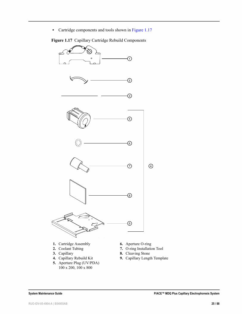
• Cartridge components and tools shown in Figure 1.17
Figure 1.17 Capillary Cartridge Rebuild Components
1. Cartridge Assembly2. Coolant Tubing3. Capillary4. Capillary Rebuild Kit5. Aperture Plug (UV/PDA)
100 x 200, 100 x 800
6. Aperture O-ring7. O-ring Installation Tool8. Cleaving Stone9. Capillary Length Template
System Maintenance Guide P/ACE™ MDQ Plus Capillary Electrophoresis System
RUO-IDV-05-4904-A | B54955AB 25 / 88
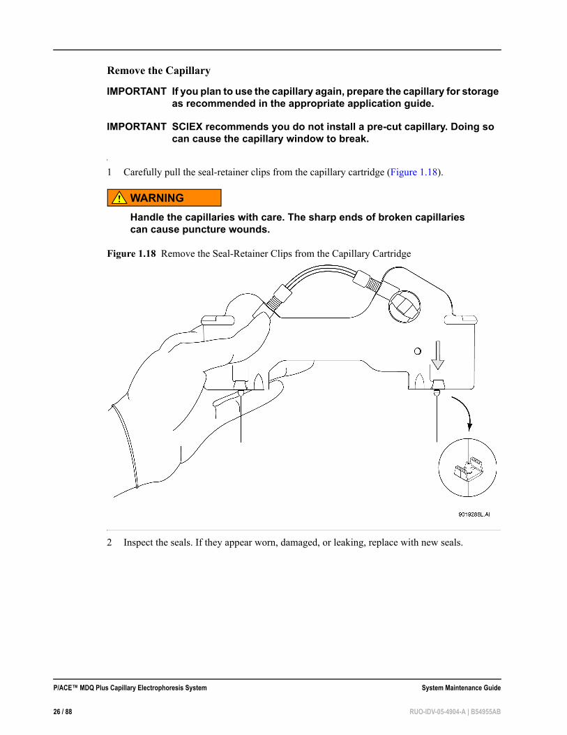
Remove the Capillary
IMPORTANT If you plan to use the capillary again, prepare the capillary for storage as recommended in the appropriate application guide.
IMPORTANT SCIEX recommends you do not install a pre-cut capillary. Doing so can cause the capillary window to break.
1 Carefully pull the seal-retainer clips from the capillary cartridge (Figure 1.18).
WARNINGHandle the capillaries with care. The sharp ends of broken capillaries can cause puncture wounds.
Figure 1.18 Remove the Seal-Retainer Clips from the Capillary Cartridge
2 Inspect the seals. If they appear worn, damaged, or leaking, replace with new seals.
P/ACE™ MDQ Plus Capillary Electrophoresis System System Maintenance Guide
26 / 88 RUO-IDV-05-4904-A | B54955AB

3 Remove the aperture by pushing from the front of the cartridge and pulling out from the back (Figure 1.19).
Figure 1.19 Removing Aperture from Cartridge (Rear View)
4 Remove the o-ring from inside the aperture. To do this, gently tap the aperture on the work surface or use a small gripping tool. Be careful not to damage the aperture.
5 Grasp the capillary at the cartridge outlet and pull the capillary firmly to remove it (Figure 1.20).
NOTE Once the capillary window is out of the cartridge, grasp the capillary above the window and continue pulling until the capillary comes completely out of the cartridge.
IMPORTANT To prevent breaking the capillary, do not pull it out of the cartridge from the inlet side. Remove the capillary from the outlet side of the cartridge only.
System Maintenance Guide P/ACE™ MDQ Plus Capillary Electrophoresis System
RUO-IDV-05-4904-A | B54955AB 27 / 88

Figure 1.20 Removing the Capillary
NOTE The following procedure is only necessary to replace damaged tubing, to replace an o-ring, or to use a different tubing length.
Replace the Coolant Tubing and Seals
1 Loosen and remove the tubing nut from the outlet side of the cartridge.
2 Remove the coolant tubing from the outlet side of the cartridge (Figure 1.21).
NOTE The tubing nut and ferrule will still be attached to the coolant tubing.
3 Loosen and remove the tubing nut from the inlet side of the cartridge.
4 Remove the coolant tubing from the inlet side of the cartridge (Figure 1.21).
NOTE The tubing nut, ferrule, and o-ring will still be attached to the coolant tubing.
1. Outlet Side Removal
P/ACE™ MDQ Plus Capillary Electrophoresis System System Maintenance Guide
28 / 88 RUO-IDV-05-4904-A | B54955AB

Figure 1.21 Coolant Tubing, Tubing Nut, Ferrule, and O-Ring
5 Remove the o-ring from the outlet side of the cartridge using a small gripping tool if necessary.
6 Use Table 1.1 to match a pre-formed coolant tubing length and loop shape with a capillary length.
For the capillary lengths in Table 1.1, use only the pre-formed coolant tubing lengths listed.
For coolant tubing lengths that are not pre-formed, use the following guidelines to create tubing loops: • For total capillary lengths longer than 60.2 cm and less than 90 cm, make one loop in the
coolant tubing. • For total capillary lengths 90 cm or longer, make two loops in the coolant tubing.
Select the capillary length from Table 1.1. Then select corresponding coolant tubing from the cartridge cooling kit, or cut coolant tubing to the length indicated in Table 1.1.
1. O-ring2. Ferrule3. Tubing Nut
System Maintenance Guide P/ACE™ MDQ Plus Capillary Electrophoresis System
RUO-IDV-05-4904-A | B54955AB 29 / 88

NOTE Use the pre-formed tubes supplied in the Coolant Tubing Kit (PN 144717) to prevent kinks and restrictions.
Table 1.1 Capillary Length
Length to Detector
Total Length Pre-Formed Coolant Tubing Description
20 cm 30.2 cm Pre-formed coolant tubing (no loop) for a total capillary length of 30.2 cm30 cm 40.2 cm Pre-formed coolant tubing for a total capillary length of 40.2 cm
40 cm 50.2 cm Pre-formed coolant tubing for a total capillary length of 50.2 cm
50 cm 60.2 cm Pre-formed coolant tubing for a total capillary length of 60.2 cm
P/ACE™ MDQ Plus Capillary Electrophoresis System System Maintenance Guide
30 / 88 RUO-IDV-05-4904-A | B54955AB

7 Slide one tubing nut, ferrule (tapered edge toward the middle of the tube length), and o-ring over each end of the new coolant tubing (Figure 1.22).
NOTE Always install a new ferrule. Used ferrules can cause leaks.
Figure 1.22 Proper Alignment of O-ring, Ferrule, and Tubing Nut
8 On the inlet side, put the coolant tubing in the cartridge and press the tubing firmly into the cartridge base. Make sure the tubing slides completely into the cartridge base (Figure 1.23).
Figure 1.23 Coolant Tubing in the Cartridge (Back View)
9 On the inlet side, push the tubing nut, ferrule, and o-ring in and tighten the tubing nut finger tight.
1. O-ring 2. Ferrule3. Tubing Nut
1. Cartridge Outlet Side2. Cartridge Inlet Side3. Tubing inserted completely into the base
System Maintenance Guide P/ACE™ MDQ Plus Capillary Electrophoresis System
RUO-IDV-05-4904-A | B54955AB 31 / 88

WARNINGDo not over tighten. Over tightening the tubing nut can cause the cartridge to break. If leaking occurs, check the cartridge housing for cracks. If there is no visible damage to the cartridge, verify that the o-ring is centered on the tubing and replace any worn or damaged tubing or ferrule.
IMPORTANT Do not sharply bend the coolant tubing. Bends in the tubing can restrict the flow of coolant.
10 On the outlet side, insert the other end of the coolant tubing in the cartridge and press the tubing firmly into the cartridge base (Figure 1.23).
11 On the outlet side, continue to press the tubing in. Push the tubing nut, ferrule, and o-ring in and tighten the tubing nut finger tight.
Replace the Capillary
1 Remove one new capillary from its storage container.
IMPORTANT Do not bend the capillary at the window. This can break the capillary.
2 Carefully uncoil and straighten the capillary. The capillary has a clear plastic protective tubing over it with an additional rectangular protective shield over the window portion. Tape down the protective tubing near the end of the capillary farthest from the window area.
3 From the end closest to the window area, pull the capillary out of the protective tubing. When the window itself is out of the protective tubing, continue pulling the capillary without pulling on the window. To do this, grasp the capillary between the window and the edge of the tubing.
4 Measure 10.2 cm from the middle of the capillary window to the outlet end. Using a felt-tip pen, mark the capillary just outside the measured length (Figure 1.24). This is the short side of the capillary closest to the window.
NOTE Do not touch the capillary window. It is fragile and finger oils reduce detection sensitivity.
NOTE Make sure the position markings are just outside the measured end points such that you remove the markings when trimming the capillary.
5 Measure the required length from the middle of the capillary window to the inlet end. Using a felt-tip pen, mark the capillary just outside the measured length. This is the long side of the capillary farthest from the window (Figure 1.24).
P/ACE™ MDQ Plus Capillary Electrophoresis System System Maintenance Guide
32 / 88 RUO-IDV-05-4904-A | B54955AB
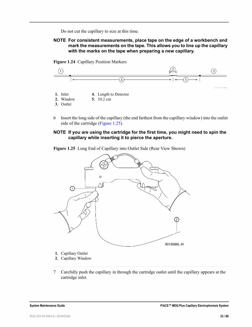
Do not cut the capillary to size at this time.
NOTE For consistent measurements, place tape on the edge of a workbench and mark the measurements on the tape. This allows you to line up the capillary with the marks on the tape when preparing a new capillary.
Figure 1.24 Capillary Position Markers
6 Insert the long side of the capillary (the end farthest from the capillary window) into the outlet side of the cartridge (Figure 1.25).
NOTE If you are using the cartridge for the first time, you might need to spin the capillary while inserting it to pierce the aperture.
Figure 1.25 Long End of Capillary into Outlet Side (Rear View Shown)
7 Carefully push the capillary in through the cartridge outlet until the capillary appears at the cartridge inlet.
1. Inlet2. Window3. Outlet
4. Length to Detector5. 10.2 cm
1. Capillary Outlet2. Capillary Window
System Maintenance Guide P/ACE™ MDQ Plus Capillary Electrophoresis System
RUO-IDV-05-4904-A | B54955AB 33 / 88

8 Pull the capillary through the cartridge from the inlet side until the capillary window appears in the center of the cartridge window (Figure 1.26).
Figure 1.26 Centering Capillary Window in Cartridge Window
Install the Aperture Clip
IMPORTANT Remove the previous o-ring before you re-install the clip.
1 Select the proper aperture for the application as recommended in the appropriate application guide.
2 From the back side of the cartridge, carefully align the center groove of the aperture clip with the capillary window and press into place (Figure 1.27).
1. Capillary Window
P/ACE™ MDQ Plus Capillary Electrophoresis System System Maintenance Guide
34 / 88 RUO-IDV-05-4904-A | B54955AB

Figure 1.27 Aligning Groove of Aperture Clip with Capillary Window
3 Go to Trim the Capillary Ends on page 38.
1. Aperture 2. Capillary3. Aperture Clip
System Maintenance Guide P/ACE™ MDQ Plus Capillary Electrophoresis System
RUO-IDV-05-4904-A | B54955AB 35 / 88

Install the LIF Probe Guide and Probe Retainer
IMPORTANT For LIF detection, use a standard cartridge and in place of the aperture clip, use a probe guide and probe retainer.
1 Carefully install the metal probe guide from the back of the cartridge.
2 Insert the probe retainer so the lock pins snap into the dimples on the probe guide (Figure 1.28).
Figure 1.28 Install the LIF Probe Guide and Probe Retainer
3 Go to Trim the Capillary Ends on page 38.
1. Probe Retainer2. Probe Guide
P/ACE™ MDQ Plus Capillary Electrophoresis System System Maintenance Guide
36 / 88 RUO-IDV-05-4904-A | B54955AB

Install the Seal-Retainer Clips
1 Carefully insert a capillary seal-retainer clip over each capillary end and press to snap into position (Figure 1.29).
NOTE Make sure both the front and back edges of each clip snap into position.
Figure 1.29 Insert the Capillary Seal Retainer Clips
2 Visually inspect the capillary ends. If they are not straight, remove and reinstall the seal-retainer clips.
1. Seal Retainer clips
System Maintenance Guide P/ACE™ MDQ Plus Capillary Electrophoresis System
RUO-IDV-05-4904-A | B54955AB 37 / 88

Trim the Capillary Ends
IMPORTANT Only trim the capillary when the sample, buffer trays, and sequence are ready and the instrument is ready to run. After you cut the capillary, store the cartridge so the protruding capillary ends are in a solution as recommended in the appropriate application guide.
1 Position the cartridge face down against the capillary-length template (Figure 1.30).
Figure 1.30 Trim the Capillary
2 Align the measurement mark on the inlet-side capillary end just below the score line on the capillary-length template.
IMPORTANT Make sure the capillary end is straight between the two lines on the template.
IMPORTANT Do not saw back and forth with the cleaving stone.
1. Cleaving Stone2. Template
P/ACE™ MDQ Plus Capillary Electrophoresis System System Maintenance Guide
38 / 88 RUO-IDV-05-4904-A | B54955AB

CAUTIONBe sure to wear safety glasses when cleaving and breaking the capillary. Capillary ends are sharp; handle them with care.
3 While holding the capillary against the template, score the inlet end of the capillary at the template cross-mark. Hold the cleaving stone at a 30 °C angle when scoring.
NOTE Make sure to cut the measurement mark off the capillary.
4 Remove the excess inlet capillary without bending the capillary.
5 Align the measurement mark on the outlet-side capillary end to just below the score line on the capillary-length template.
IMPORTANT Make sure the capillary end is straight between the two lines on the template.
IMPORTANT Do not saw back and forth with the cleaving stone.
CAUTIONBe sure to wear safety glasses when cleaving and breaking the capillary. Capillary ends are sharp; handle them with care.
6 While you hold the capillary against the template, score the outlet end of the capillary at the template cross-mark. Hold the cleaving stone at a 30 °C angle when scoring.
NOTE Make sure to cut the measurement mark off the capillary.
7 Remove the excess outlet capillary without bending the capillary.
8 Inspect the capillary ends with a magnifying lens to make sure that they are smooth and not jagged. Figure 1.31 shows a smooth cut 1 and jagged cuts under 2. Only cut 1 is acceptable.
System Maintenance Guide P/ACE™ MDQ Plus Capillary Electrophoresis System
RUO-IDV-05-4904-A | B54955AB 39 / 88
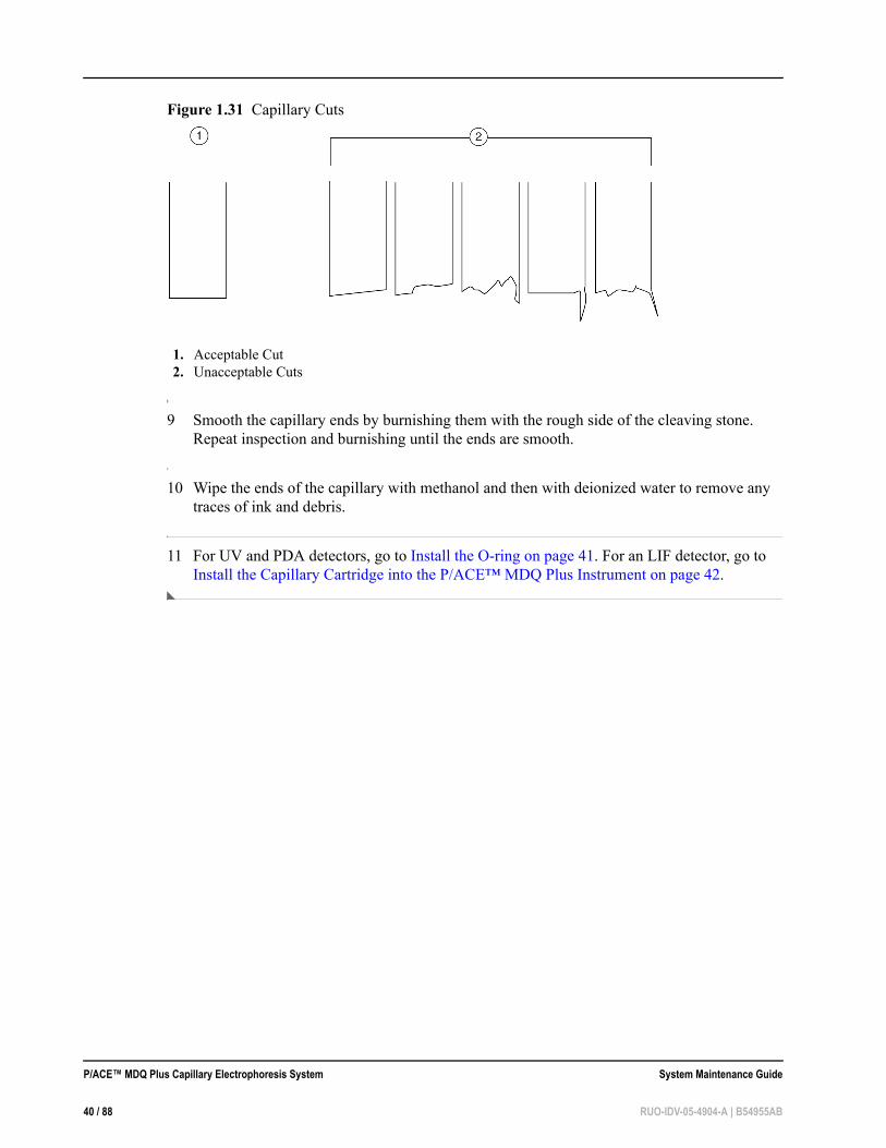
Figure 1.31 Capillary Cuts
9 Smooth the capillary ends by burnishing them with the rough side of the cleaving stone. Repeat inspection and burnishing until the ends are smooth.
10 Wipe the ends of the capillary with methanol and then with deionized water to remove any traces of ink and debris.
11 For UV and PDA detectors, go to Install the O-ring on page 41. For an LIF detector, go to Install the Capillary Cartridge into the P/ACE™ MDQ Plus Instrument on page 42.
1. Acceptable Cut2. Unacceptable Cuts
P/ACE™ MDQ Plus Capillary Electrophoresis System System Maintenance Guide
40 / 88 RUO-IDV-05-4904-A | B54955AB

Install the O-ring
1 From the front side of the cartridge, place the retainer o-ring in the aperture clip hole.
NOTE Use an o-ring only with 100 x 200 and 100 x 800 apertures. Do not use an o-ring with the LIF probe guide.
WARNINGThe o-ring must lie flat on top of the capillary window.
2 With the o-ring insertion tool, carefully press the tool until the o-ring seats in the aperture clip (Figure 1.32).
Figure 1.32 Seat the O-ring in the Aperture-Clip Hole–Front View
3 The cartridge is now ready for use.
NOTE For capillary equilibration and storage conditions, please refer to the appropriate application guide.
To use the capillary immediately, follow the instructions in Install the Capillary Cartridge into the P/ACE™ MDQ Plus Instrument.
1. Insertion Tool2. O-ring3. Aperture Clip Hole
System Maintenance Guide P/ACE™ MDQ Plus Capillary Electrophoresis System
RUO-IDV-05-4904-A | B54955AB 41 / 88

Install the Capillary Cartridge into the P/ACE™ MDQ Plus Instrument
Required Materials • A fully assembled capillary cartridge, which includes an installed capillary
1 Lift the outer door and the cartridge cover door at the front of the P/ACE™ MDQ Plus instrument (Figure 1.33 and Figure 1.34).
Figure 1.33 Cartridge Cover Door
1. Outer Door or Sample Cover Door2. Inner Cartridge Cover Door3. Indicators4. Fluid Fill Port
5. Sample Trays6. Buffer Trays7. Fluid Bubble Indicator8. Convenience Switch
P/ACE™ MDQ Plus Capillary Electrophoresis System System Maintenance Guide
42 / 88 RUO-IDV-05-4904-A | B54955AB

Figure 1.34 Interface Block
2 Loosen the knobs and lift the clamp bar.
3 Position the capillary cartridge over the cartridge interface block and carefully lower the cartridge into position.
1. Outer Door or Sample Cover Door2. Detector3. Two-ended Fiber Optic Cable
4. Clamp Bar5. Capillary Cartridge6. Interface Block
System Maintenance Guide P/ACE™ MDQ Plus Capillary Electrophoresis System
RUO-IDV-05-4904-A | B54955AB 43 / 88

4 Lower the clamp bar and tighten the knobs.
5 Lower the cartridge cover door.
NOTE To ensure correct performance, replace the capillary cartridge aperture after three months of use.
Install the Universal Vials and Caps
Fill the Universal VialsNOTE When you fill universal vials, remember:
• Vial caps must be clean and completely dry before each use. • Never reuse vial caps. • Do not overfill vials. An over-full vial sometimes causes hydrostatic
pressure, which pushes liquid into the pressure lines. • Do not under-fill the vial or let the liquid level become too low. Low
liquid level in separation vials can cause poor separations.
Required Materials • Universal vials • Universal vial caps
1 Fill the universal vials as shown in Figure 1.35. For the fill volume, refer to the appropriate application guide. Do not put more than 1.7 mL in a vial.
P/ACE™ MDQ Plus Capillary Electrophoresis System System Maintenance Guide
44 / 88 RUO-IDV-05-4904-A | B54955AB

Figure 1.35 Universal Vials
2 Put the cap on the vial and press it into position.
Fill the Micro Vials
Required Materials • Micro vials • Universal vials • Universal vial caps
NOTE Very small samples can evaporate into the space inside the micro vial holder. (The micro vial holder is the built-in plastic support structure that secures the micro vial inside the universal vial.) Minimize this evaporation by placing 200 µL of water in the bottom of the universal vial.
1. Universal Vial Cap2. Maximum Fill Level3. Universal Vials
System Maintenance Guide P/ACE™ MDQ Plus Capillary Electrophoresis System
RUO-IDV-05-4904-A | B54955AB 45 / 88

1 Using care as not to introduce any bubbles, fill the micro vial with at least 100 µL of sample (Figure 1.36).
Figure 1.36 Micro Vials
2 Place the micro vial in the universal vial.
3 Put the cap on the universal vial.
4 Put the capped vial in the tray.
1. Universal Cap2. Micro Vial
3. Universal Vial4. Micro Vial inside Universal Vial
P/ACE™ MDQ Plus Capillary Electrophoresis System System Maintenance Guide
46 / 88 RUO-IDV-05-4904-A | B54955AB

CHAPTER 2
Maintenance Procedures
This chapter contains the following maintenance procedures for the SCIEX P/ACE™ MDQ Plus
capillary electrophoresis system:• Clean the Ejecting Levers, Electrodes, and Interface Block on page 48 • Refill the Capillary Coolant on page 53 • Clean the Fiber Optic Cable (UV and PDA Detectors) on page 54 • Replace the Deuterium Lamp on page 56 • Procedures for Instrument Care on page 62 • Procedures for LIF Detector Care and Maintenance on page 65
WARNINGDisconnect the power before any instrument disassembly. Failure to do so can cause electrical shock or other injury.
WARNINGMaintenance or repair procedures not specifically described in this manual present a risk of electrical shock or injury. Refer additional servicing to SCIEX.
WARNINGDo not attempt to defeat any of the instrument interlocks or safety mechanisms.
System Maintenance Guide P/ACE™ MDQ Plus Capillary Electrophoresis System
RUO-IDV-05-4904-A | B54955AB 47 / 88

Clean the Ejecting Levers, Electrodes, and Interface Block
SCIEX recomends cleaning the ejecting levers and electrodes once a week and when switching applications. The interface block should be cleaned as needed.
Required Materials • Lint-free wipes • Mirror • Pen light • Cotton swabs • 150 mL of DDI water • Methanol • Beaker • Electrode tool
1 Follow the instructions in Remove the Ejecting Levers on page 49.
2 Immerse both levers in a beaker containing at least 150 mL of DDI water.
3 Follow the instructions in Remove the Electrodes on page 50.
4 Immerse both electrodes in the DDI water with the ejecting levers.
5 Sonicate these four parts for five minutes.
6 Retrieve the parts and dry them thoroughly with a lint-free wipe.
7 Replace the electrodes (refer to Replace the Electrodes in the Interface Block on page 52).
8 Replace the ejecting levers (refer to Replace the Ejecting Levers on page 52).
CAUTIONDo not place fingers directly below the electrodes when installing ejecting levers. The electrode ends are sharp; handle them with care.
9 Use cotton swabs to clean the interface block, electrodes, and opening lever surfaces with water followed by methanol. Allow the interface block, electrodes, and opening lever surfaces to dry.
P/ACE™ MDQ Plus Capillary Electrophoresis System System Maintenance Guide
48 / 88 RUO-IDV-05-4904-A | B54955AB
10 Inspect the interface block using a mirror and pen light. If needed, repeat the cleaning process until the interface block is clean.
11 Reinstall the capillary cartridge in the interface block.
12 Lower the clamp bar and tighten the two thumbscrews.
13 Close the cartridge cover door.
Remove the Ejecting Levers
1 Use the Direct Control window to move the trays to the load position.
2 Lift the cartridge cover door.
3 Loosen the two thumbscrews and lift the clamp bar.
4 Remove the capillary cartridge from the interface block.
5 If the trays are still in your way, remove them for access to both ejecting levers.
6 Remove one of the ejecting levers by grasping it with both hands and pulling down firmly (Figure 2.1). Repeat for the second lever.
System Maintenance Guide P/ACE™ MDQ Plus Capillary Electrophoresis System
RUO-IDV-05-4904-A | B54955AB 49 / 88

Figure 2.1 Interface Block, Electrodes, and Ejecting Levers
Remove the Electrodes
1 If needed, follow the instructions in Remove the Ejecting Levers on page 49.
2 Align the electrode tool flush with the bottom of the interface block.
3 Push straight forward under the interface block to capture the electrode in the tool.
1. Interface Block2. Electrodes3. Ejecting Levers
P/ACE™ MDQ Plus Capillary Electrophoresis System System Maintenance Guide
50 / 88 RUO-IDV-05-4904-A | B54955AB

4 Make sure the nub at the end of the electrode tool handle fits into the notch on the interface block as shown in the circled area of Figure 2.2.
Figure 2.2 Remove Electrodes from Interface Block
5 Pry gently upward on the rear of the electrode tool to remove the electrode from the interface block.
6 Remove the electrode from the electrode tool. Repeat for second electrode.
1. Electrode Tool2. Electrode3. Nub at end of Electrode Tool Handle
System Maintenance Guide P/ACE™ MDQ Plus Capillary Electrophoresis System
RUO-IDV-05-4904-A | B54955AB 51 / 88

Replace the Electrodes in the Interface Block
1 Place an electrode in the tool with the electrode key facing you (Figure 2.3).
Figure 2.3 Install an Electrode into the Interface Block
2 Align the tool below the notch and parallel to the bottom of the interface block.
3 Press upward to snap the electrode into the interface block.
4 Remove the tool by pulling straight back. Repeat for the second electrode.
Replace the Ejecting Levers
CAUTIONDo not place fingers directly below the electrodes when installing ejecting levers. Electrode ends are sharp; handle them with care.
1 Align the o-ring and electrode hole in the lever directly under the electrode. The short cylinder side of the lever should be under the spring.
2 With your fingers on the sides of the lever, press the lever up into the interface block until it snaps into place.
3 Repeat for the second lever.
1. Electrode Tool2. Electrode Key
P/ACE™ MDQ Plus Capillary Electrophoresis System System Maintenance Guide
52 / 88 RUO-IDV-05-4904-A | B54955AB

Refill the Capillary Coolant
Required Materials • Capillary cartridge coolant (PN 359976) • 150 mL syringe • Coolant Fill Adapter (PN 144647)
1 Open the sample cover (Figure 2.4).
Figure 2.4 Capillary Coolant Installation
2 Attach the coolant fill adapter to the coolant fill port.
3 Fill the syringe with 120 mL of coolant.
1. Outer Door or Sample Cover (open)2. Inner Door or Cartridge Cover (open)3. Indicators4. Fluid Fill Port
5. Sample Trays6. Buffer Trays7. Fluid Bubble Indicator8. Convenience Switch
System Maintenance Guide P/ACE™ MDQ Plus Capillary Electrophoresis System
RUO-IDV-05-4904-A | B54955AB 53 / 88
4 Fill the coolant supply until the coolant level in the sight-tube is approximately 75% full.
5 Remove the syringe and close the sample cover.
6 The coolant syringe comes with a plunger. When adding coolant, do not use the plunger. Gravity supplies enough force to pull the coolant into the system. Using the plunger can introduce too much pressure to the coolant system and can cause damage.
Clean the Fiber Optic Cable (UV and PDA Detectors)
Required Materials • Non-abrasive lens tissue • Analytical grade methanol, ethanol, or isopropanol
CAUTIONDo not touch the fiber optic surface with your fingers as oils from your skin can degrade performance.
1 Use Direct Control to move the trays to the load position.
2 Lift the cartridge cover door (Figure 2.5).
P/ACE™ MDQ Plus Capillary Electrophoresis System System Maintenance Guide
54 / 88 RUO-IDV-05-4904-A | B54955AB
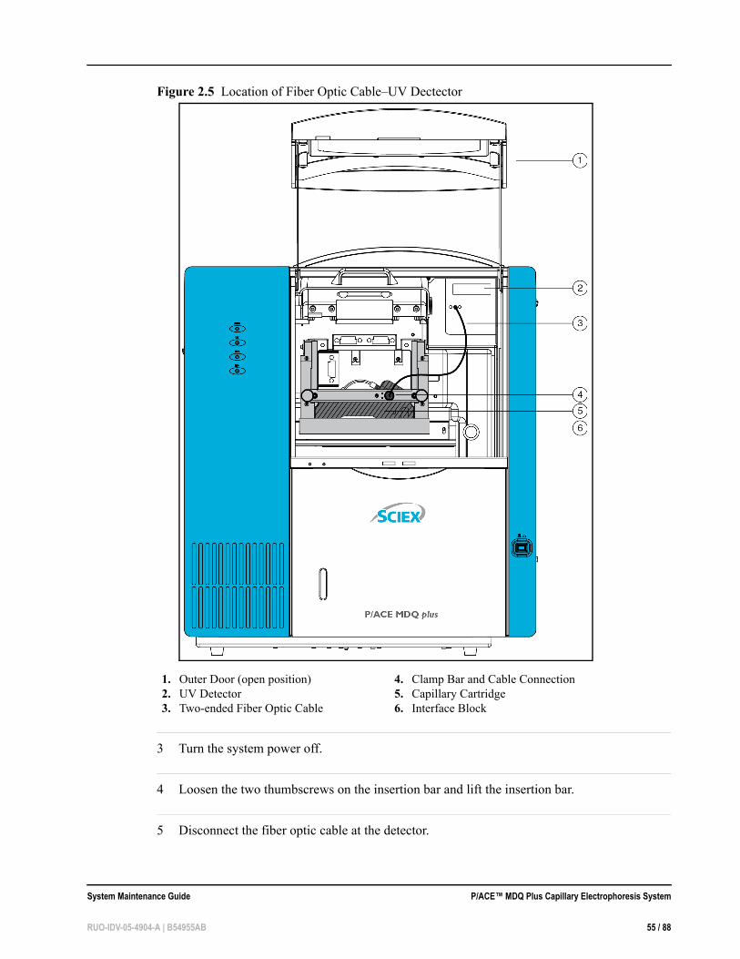
Figure 2.5 Location of Fiber Optic Cable–UV Dectector
3 Turn the system power off.
4 Loosen the two thumbscrews on the insertion bar and lift the insertion bar.
5 Disconnect the fiber optic cable at the detector.
1. Outer Door (open position)2. UV Detector3. Two-ended Fiber Optic Cable
4. Clamp Bar and Cable Connection5. Capillary Cartridge6. Interface Block
System Maintenance Guide P/ACE™ MDQ Plus Capillary Electrophoresis System
RUO-IDV-05-4904-A | B54955AB 55 / 88

6 Disconnect the fiber optic cable at the clamp arm.
7 Moisten the lens tissue with alcohol.
8 Clean the surface of each fiber optic cable connector and allow each connector to dry before reconnecting.
9 Reconnect the fiber optic cable at the clamp bar.
10 Reconnect the fiber optic cable at the detector.
11 When all fiber optic cable connectors are cleaned and reconnected, close the cartridge cover door.
Replace the Deuterium Lamp
If the baseline is excessively noisy or the lamp will not strike, the lamp may need replacement. The following procedure describes how to change the lamp.
Required Materials • Deuterium lamp • 7/64 inch hex wrench
WARNINGIf the P/ACE™ MDQ Plus instrument has been on for any length of time, the deuterium lamp will be very hot. To prevent burning your fingers, allow the lamp to cool before replacing.
1 Use Direct Control to move the trays to the load position.
2 Lift the cartridge cover door (Figure 2.6 and Figure 2.7).
P/ACE™ MDQ Plus Capillary Electrophoresis System System Maintenance Guide
56 / 88 RUO-IDV-05-4904-A | B54955AB

Figure 2.6 How to Change the Lamp
1. Outer Door or Sample Cover (open)2. Inner Door or Cartridge Cover (open)3. Indicators4. Fluid Fill Port
5. Sample Trays6. Buffer Trays7. Fluid Bubble Indicator8. Convenience9. Switch
System Maintenance Guide P/ACE™ MDQ Plus Capillary Electrophoresis System
RUO-IDV-05-4904-A | B54955AB 57 / 88

Figure 2.7 Capillary Cartridge Door
3 Turn the system power off and allow enough time for the lamp to cool.
4 Loosen the two thumbscrews on the clamp bar and lift the bar.
5 Remove the capillary cartridge from the interface block.
1. Outer Door (open position)2. UV Detector3. Two-ended Fiber Optic Cable
4. Clamp Bar and Cable Connection5. Capillary Cartridge6. Interface Block
P/ACE™ MDQ Plus Capillary Electrophoresis System System Maintenance Guide
58 / 88 RUO-IDV-05-4904-A | B54955AB

6 Loosen the two thumbscrews and remove the optics source assembly (Figure 2.8).
Figure 2.8 How to Remove the Optics Assembly
7 Pull the assembly forward and place it on a clean work surface.
8 Open the deuterium lamp access cover on the back of the optics source assembly. Disconnect the lamp power plug (Figure 2.9).
1. Access Door Catch2. Access Door3. Thumbscrews (one on each side)
System Maintenance Guide P/ACE™ MDQ Plus Capillary Electrophoresis System
RUO-IDV-05-4904-A | B54955AB 59 / 88
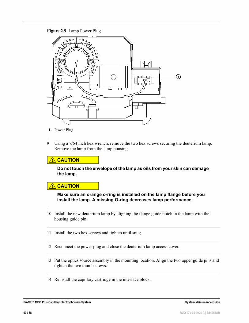
Figure 2.9 Lamp Power Plug
9 Using a 7/64 inch hex wrench, remove the two hex screws securing the deuterium lamp. Remove the lamp from the lamp housing.
CAUTIONDo not touch the envelope of the lamp as oils from your skin can damage the lamp.
CAUTIONMake sure an orange o-ring is installed on the lamp flange before you install the lamp. A missing O-ring decreases lamp performance.
10 Install the new deuterium lamp by aligning the flange guide notch in the lamp with the housing guide pin.
11 Install the two hex screws and tighten until snug.
12 Reconnect the power plug and close the deuterium lamp access cover.
13 Put the optics source assembly in the mounting location. Align the two upper guide pins and tighten the two thumbscrews.
14 Reinstall the capillary cartridge in the interface block.
1. Power Plug
P/ACE™ MDQ Plus Capillary Electrophoresis System System Maintenance Guide
60 / 88 RUO-IDV-05-4904-A | B54955AB

15 Lower the clamp bar and tighten the two thumbscrews.
16 Close the cartridge cover door.
17 Turn on the power.
18 Start the 32 Karat software.
19 Click Control > Diagnostics > View. The appropriate diagnostics dialog for your detector opens (Figure 2.10 and Figure 2.11).
Figure 2.10 PDA Detector Installed–Diagnostics Dialog
System Maintenance Guide P/ACE™ MDQ Plus Capillary Electrophoresis System
RUO-IDV-05-4904-A | B54955AB 61 / 88

Figure 2.11 UV Detector Installed–Diagnostics Window
20 Click Control > Diagnostics > Set Lamp Hours. The Lamp Hours of Use dialog appears. (Figure 2.12).
Figure 2.12 Lamp Hours of Use Dialog
21 In Lamp Hours, type 0.
22 Click OK.
Procedures for Instrument Care
• Replace the Quad Rings on page 62 • Replace the Fuses on page 63
Replace the Quad RingsIf coolant is leaking between the interface block and cartridge, the quad-rings might require replacement. The following procedure describes how to change the quad-rings. You must have new quad-rings to do the replacement.
1 Use the Direct Control window to move the trays to the load position.
2 Lift the cartridge cover door.
P/ACE™ MDQ Plus Capillary Electrophoresis System System Maintenance Guide
62 / 88 RUO-IDV-05-4904-A | B54955AB

3 Loosen the two thumbscrews and lift the clamp bar.
4 Check cartridge coolant tubing connections for leaks.
5 Remove the capillary cartridge from the interface block.
6 Find the quad rings in the interface block. Use the thumbnail and forefinger to remove the quad rings.
7 Install the new quad ring in the quad ring recess of the interface block.
8 Reinstall the capillary cartridge in the interface block.
9 Lower the clamp bar and tighten the two thumbscrews.
10 Close the cartridge cover door.
Replace the Fuses
CAUTIONIt is important to find the cause of fuse failure before you replace the fuses.
CAUTIONMake sure to replace the fuses with the correct type and rating for continued protection against risk of fire and/or improper instrument operation.
CAUTIONIf the fuses continue to blow after being replaced, contact SCIEX service for additional assistance
Required Materials • #2 flat screwdriver • Two T8.0 A 250 V, 5 mm x 20 mm glass-cartridge fuses
1 Turn off the instrument power and disconnect the power cord from the AC power outlet.
System Maintenance Guide P/ACE™ MDQ Plus Capillary Electrophoresis System
RUO-IDV-05-4904-A | B54955AB 63 / 88

2 Using the flat-tip screwdriver, remove the fuse block (Figure 2.13).
Figure 2.13 Replacing Fuses
3 Replace the fuses.
4 Reinstall the fuse block and reconnect the power cable.
1. Fuse Block2. Air Conditioning Vents3. External Connections Panel
P/ACE™ MDQ Plus Capillary Electrophoresis System System Maintenance Guide
64 / 88 RUO-IDV-05-4904-A | B54955AB

Procedures for LIF Detector Care and Maintenance
WARNINGThe 488 nm laser module emits laser light that can cause serious damage to the eyes. Servicing of the laser should be done only by a SCIEX Field Service Employee.
Inspect the LIFThe LIF detector system is designed to prevent laser light exposure outside the laser box, fiber cable, and detector. To make sure the laser light is contained, regularly check the following parts of the system.
• Visually inspect the full length of the fiber optic cable to make sure it is in good condition. • Visually inspect the laser module housing to verify that no panels are loose. Loose panels can
allow dangerous access to laser energy inside the module. • Verify operation of the interlock.
CAUTIONIf the interlock is defeated, potentially harmful laser power of up to 3mW can be accessible in the interior or can be emitted from the fiber optic cable.
Clean the LIF ModulesThe outside surfaces of the detector and laser module can be cleaned by wiping with a clean, damp cloth. If necessary, a mild detergent can be used. Wipe the outside surfaces with a soft, dry cloth after cleaning.
The filters are delicate optical components that must be protected from dirt, dust, and fingerprint contamination. When installed in the filter housing, the filters are protected from contamination and normally do not require cleaning. Due to the risk of damaging a filter during the cleaning process, DO NOT clean a filter unless it is dirty enough to affect system performance.
Store the LIF ProbeWhen the LIF detector is not in use, install the probe in the Probe Holder on the 488 nm laser module. This gives a mechanical protection for the probe and shields it from dust and other particles.
System Maintenance Guide P/ACE™ MDQ Plus Capillary Electrophoresis System
RUO-IDV-05-4904-A | B54955AB 65 / 88

P/ACE™ MDQ Plus Capillary Electrophoresis System System Maintenance Guide
66 / 88 RUO-IDV-05-4904-A | B54955AB

CHAPTER 3
Connect the System to a Mass Spectrometer
This chapter contains the following procedures for interfacing the SCIEX P/ACE™ MDQ Plus capillary electrophoresis system with a mass spectrometer: • Install the Capillary in the Standard Cartridge on page 68 • Install the Capillary in the EDA-Only Cartridge on page 71 • Install the Ground Connection on page 73
About CE-MS Mode
In CE-MS mode, the coolant tubing and capillary extend outside the to the External Detector Adapter (EDA) block. The EDA block is a device that allows the capillary to exit the P/ACE™ MDQ Plus instrument and supplies a return path for the capillary coolant. The EDA block can be used with the standard cartridge or the EDA-only cartridge. When you use this device, special coolant tubing is required.
The standard cartridge accommodates capillaries with an external diameter of 375 µm and allows use of the P/ACE™ MDQ Plus instrument UV and PDA detectors. The length to the detector with this cartridge is approximately 10 cm. The EDA-only cartridge does not allow use of the CE detector.
WARNINGTo prevent the risk of electric shock, when the high voltage is turned on do not touch the capillary.
WARNINGThe end of the capillary is a sharp object. To prevent the risk of injury, handle the capillary with care when inserting it into the cartridge, when handling the cartridge, and when attaching external devices.
System Maintenance Guide P/ACE™ MDQ Plus Capillary Electrophoresis System
RUO-IDV-05-4904-A | B54955AB 67 / 88

Install the Capillary in the Standard Cartridge
Required Materials • 100 cm capillary with a window 15 cm from the end • External detector adapter kit (PN A61216) • Standard cartridge (PN 144738) or CE/MS cartridge (PN 149044) • Capillary length template • Cleaving stone
Figure 3.1 Standard Cartridge
1 If a cartridge is already present in the P/ACE™ MDQ Plus instrument, remove it.
1 Prepare a 100 cm capillary with a window at 15 cm from one end.
2 Remove the clip and double seal from the bottom of the cartridge on the aperture side.
3 If present, remove the coolant tubing nut at the aperture side of the cartridge and remove the coolant tubing from the cartridge. Verify that the coolant o-ring is removed from the cartridge. Also remove the capillary.
4 Remove the nut and seal from the external detector adapter.
5 Hold the new capillary at the end farthest from the window. Insert this end of the capillary into the bottom of the cartridge and push the capillary in through the aperture and out through the top of the cartridge.
6 Pull the capillary out from the top of the cartridge until the window is centered in the aperture.
901027.AI
P/ACE™ MDQ Plus Capillary Electrophoresis System System Maintenance Guide
68 / 88 RUO-IDV-05-4904-A | B54955AB
7 If it the aperture o-ring is present, remove it. Install the aperture by pressing it in squarely from the back side of the cartridge.
8 Install the double seal and clip over the capillary and onto the cartridge.
9 Trim the capillary at the bottom of the cartridge using the capillary length template and cleaving stone.
NOTE Do not trim the long end of the capillary now.
10 Put the nut, ferrule, and o-ring on the coolant tubing.
11 Feed the long end of the capillary through the coolant tubing until the capillary emerges from the external detector adapter.
12 Insert the coolant tubing into the cartridge until the tubing is completely seated. Make sure the o-ring stays centered on the end of the coolant tubing and finger-tighten the nut into the cartridge. Do not over-tighten the nut.
13 Tighten the coolant nut into the external detector adapter.
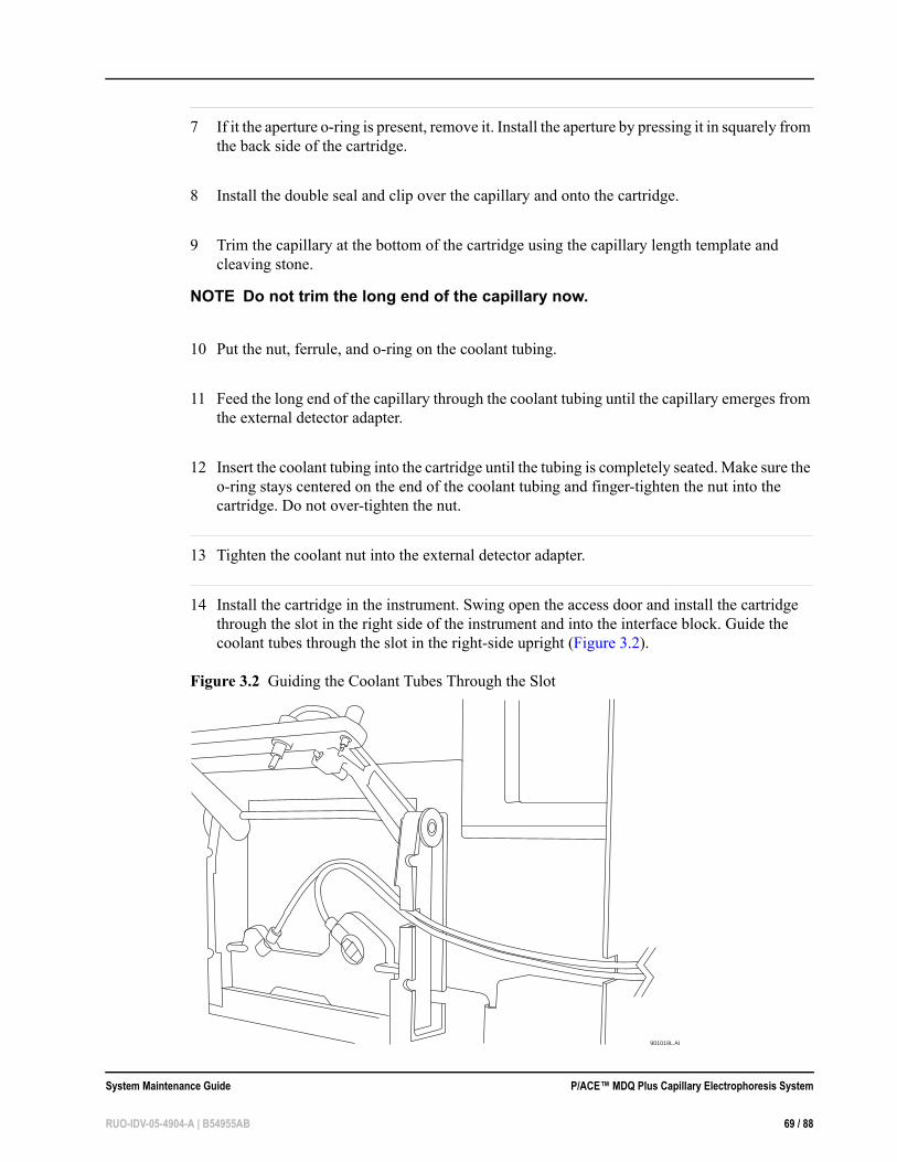
14 Install the cartridge in the instrument. Swing open the access door and install the cartridge through the slot in the right side of the instrument and into the interface block. Guide the coolant tubes through the slot in the right-side upright (Figure 3.2).
Figure 3.2 Guiding the Coolant Tubes Through the Slot
901019L.AI
System Maintenance Guide P/ACE™ MDQ Plus Capillary Electrophoresis System
RUO-IDV-05-4904-A | B54955AB 69 / 88

15 Lower the clamp bar and tighten the screws.
16 Insert the capillary adapter body into the slot in the right side of the instrument. Secure the capillary adapter with the locking ring.
17 Slide the door closed, then close the cartridge cover door and the outer door.
18 Adjust the end of the capillary coming from the coolant tubing into the MS adapter so that the shortest length of capillary is exposed.
19 Remove approximately 2 mm of polyimide coating from the outside of the capillary.
P/ACE™ MDQ Plus Capillary Electrophoresis System System Maintenance Guide
70 / 88 RUO-IDV-05-4904-A | B54955AB

Install the Capillary in the EDA-Only Cartridge
Figure 3.3 EDA-only Cartridge
Required Materials • 100 cm capillary • EDA cartridge (PN 144829), includes cartridge and external detector adapter • Capillary length template • Cleaving stone
1 If a cartridge is already present in the P/ACE™ MDQ Plus instrument, remove it.
2 Prepare a 100 cm capillary.
3 Remove the clip and double seal from the bottom of the cartridge.
4 Remove the nut and seal from the external detector adapter.
5 Hold the capillary at the end farthest from the window. Insert this end of the capillary into the bottom of the cartridge and push the capillary in and out through the top of the cartridge.
6 Continue to feed the capillary through the coolant tubing until the capillary emerges from the external detector adapter.
7 Install the double seal and clip over the capillary and onto the cartridge.
System Maintenance Guide P/ACE™ MDQ Plus Capillary Electrophoresis System
RUO-IDV-05-4904-A | B54955AB 71 / 88

8 Trim the capillary at the bottom of the cartridge using the capillary length template and cleaving stone.
NOTE Do not trim the long end of the capillary now.
9 Feed the long end of the capillary through the coolant tubing until the capillary emerges from the external detector adapter.
10 Install the cartridge in the instrument. Swing open the access door and install the cartridge through the slot in the right side of the instrument and into the interface block. Guide the coolant tubes through the slot in the right-side upright (Figure 3.2).
11 Lower the clamp bar and tighten the screws.
12 Insert the capillary adapter body into the slot in the right side of the instrument. Secure the capillary with the locking ring.
13 Slide the EDA door closed, then close the cartridge cover door and the outer door.
14 Adjust the end of the capillary coming from the coolant tubing into the MS adapter so that the shortest length of capillary is exposed.
15 Remove approximately 2 mm of polyimide coating from the outside of the capillary.
P/ACE™ MDQ Plus Capillary Electrophoresis System System Maintenance Guide
72 / 88 RUO-IDV-05-4904-A | B54955AB
Install the Ground Connection
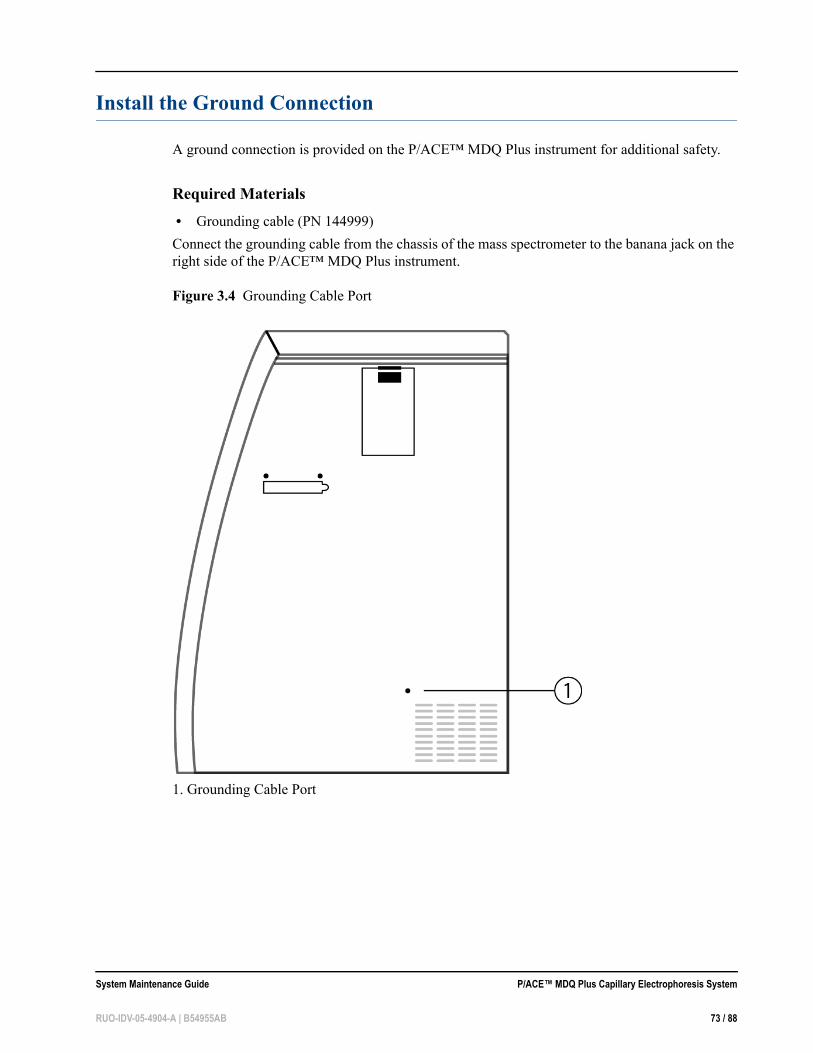
A ground connection is provided on the P/ACE™ MDQ Plus instrument for additional safety.
Required Materials • Grounding cable (PN 144999)Connect the grounding cable from the chassis of the mass spectrometer to the banana jack on the right side of the P/ACE™ MDQ Plus instrument.
Figure 3.4 Grounding Cable Port
1. Grounding Cable Port
System Maintenance Guide P/ACE™ MDQ Plus Capillary Electrophoresis System
RUO-IDV-05-4904-A | B54955AB 73 / 88

P/ACE™ MDQ Plus Capillary Electrophoresis System System Maintenance Guide
74 / 88 RUO-IDV-05-4904-A | B54955AB

APPENDIX A
Evaluating UV Filters
Overview
By default, the SCIEX P/ACE™ MDQ Plus Capillary Electrophoresis System is configured with a UV detector. Absorbance wavelength is determined by the filters installed on the system. Seven positions are available for different wavelength filters. When a method is run, the instrument selects the specified filter and positions it in the optical path. This makes it important to verify the correct wavelengths are associated with their respective filter positions. Also, filter characteristics can change with time, heat, humidity, exposure to UV, and handling. For this reason, it is important to periodically check or replace these filters. This appendix describes a method for testing UV filters using a certified spectrophotometer.
Spectrophotometers are typically not designed for the purpose of analyzing filters. More commonly, they are set up for analysis of solutions contained in cuvettes. To use a spectrophotometer to measure the UV filters for the P/ACE™ MDQ Plus system, it is necessary to position the filter at a height so that the optical beam of the spectrophotometer passes through the center of the filter. A special filter holder tool (PN A32981) is available for Beckman Coulter model DU 700 series and model DU 800 spectrophotometers (Figure A.1).
Figure A.1 Filter Holder Tool
System Maintenance Guide P/ACE™ MDQ Plus Capillary Electrophoresis System
RUO-IDV-05-4904-A | B54955AB 75 / 88

The default filters for the UV detector are 200 nm, 214 nm, 230 nm, and 254 nm. Using the tool shown above, these filters can be scanned using a Beckman Coulter DU 800 or DU 700 Series spectrophotometer.
The filters used for UV detection all have a center wavelength ( ) of ± 2 nm. To find , use the following equation.
where
Figure A.2 shows a scan of a 214 nm filter using a qualified DU 800 spectrophotometer.
= Center wavelength
= Half power points at beginning and ending wavelengths, typically referred to as Full Width at Half Maximum (FWHM)
= The point of the trace to the left of the apex at 1/2 the maximum % Transmission.
= The point of the trace to the right of the apex at 1/2 the maximum % Transmission.
λc λc
λc2λ12λ2λ1 λ2+-------------------=
λc
λ1 and λ2
λ1
λ2
P/ACE™ MDQ Plus Capillary Electrophoresis System System Maintenance Guide
76 / 88 RUO-IDV-05-4904-A | B54955AB

Figure A.2 Calculating Center Wavelength using Full Width at Half Height
The following equation shows the calculation of the center wavelength, using the values from the plot in Figure A.2:
λc2 206.4 nm( ) 220.8 nm( )
206.4 nm 220.8 nm+----------------------------------------------------------- 213.2 nm==
System Maintenance Guide P/ACE™ MDQ Plus Capillary Electrophoresis System
RUO-IDV-05-4904-A | B54955AB 77 / 88

Figure A.3 Calculated Result of Center Wavelength
Because filter characteristics can change with time, heat, humidity, exposure to UV light, and handling it is important to periodically check or replace these filters. For most applications a small change is not significant. Pass/fail criteria for filter characteristics will vary depending on the application and sample. Establish these criteria as a part of the overall validation of your method.
P/ACE™ MDQ Plus Capillary Electrophoresis System System Maintenance Guide
78 / 88 RUO-IDV-05-4904-A | B54955AB

APPENDIX B
Performance Tests for the LIF Detector
LIF detection differs from absorbance detection in some important ways. An absorbance detector
measures a small intensity difference in a high-intensity light source. This is an effective technique because the percentage of light does not change as the source light intensity changes. This means peak response for a sample remains constant as the lamp ages or when a lamp is changed. With LIF detection, low light intensity is measured from a dark background. These low intensities are more easily influenced by changes in the optical path. A calibration can be performed to correct for these influences by using a SCIEX-supplied test mix. For this example, the environment is LIF calibration using the 488 nm laser with fluorescein.Relative Fluorescent Units (RFU)
LIF detection systems are prone to give different response as changes are made in the optical path. This means a sample of known concentration can yield different results after a capillary is changed or if the separation is run on a different instrument. Due to this uncertainty, LIF detector response is annotated in units of Relative Fluorescent Units (RFU) as opposed to lumens or another unit of light energy. This is generally acceptable for capillary electrophoresis detection provided you can associate a sample concentration with a detector response.
To provide performance specifications for the LIF detector, it was necessary to develop a fluorescent test mix solution. 1 x 10⁻⁷ M fluorescein sodium salt in water was chosen for the performance test mix.
Calibration Correction Factor (CCF)
Several different LIF sources and detectors were used to establish an expected response value for the LIF test mix. For the capillary used in the performance test (75 µm i.d., 60 cm total length, bare fused-silica), the expected detector response was determined to be 35. Most of the systems tested were within ± 10% of this value.
System Maintenance Guide P/ACE™ MDQ Plus Capillary Electrophoresis System
RUO-IDV-05-4904-A | B54955AB 79 of 88
To correct for this variability, a calibration correction factor (CCF) can be calculated for each system as follows:
Expected response (Target) = 35Measured response = M
CCF = 35/M
Applying the CCF
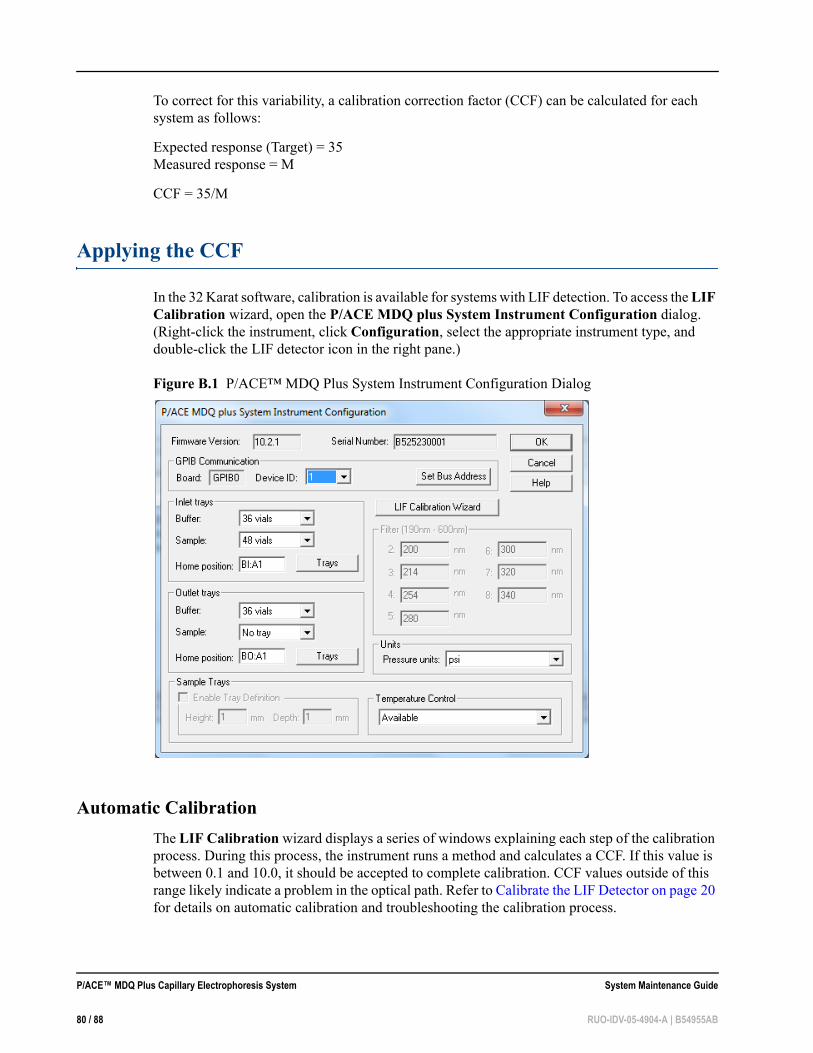
In the 32 Karat software, calibration is available for systems with LIF detection. To access the LIF Calibration wizard, open the P/ACE MDQ plus System Instrument Configuration dialog. (Right-click the instrument, click Configuration, select the appropriate instrument type, and double-click the LIF detector icon in the right pane.)
Figure B.1 P/ACE™ MDQ Plus System Instrument Configuration Dialog
Automatic CalibrationThe LIF Calibration wizard displays a series of windows explaining each step of the calibration process. During this process, the instrument runs a method and calculates a CCF. If this value is between 0.1 and 10.0, it should be accepted to complete calibration. CCF values outside of this range likely indicate a problem in the optical path. Refer to Calibrate the LIF Detector on page 20 for details on automatic calibration and troubleshooting the calibration process.
P/ACE™ MDQ Plus Capillary Electrophoresis System System Maintenance Guide
80 / 88 RUO-IDV-05-4904-A | B54955AB
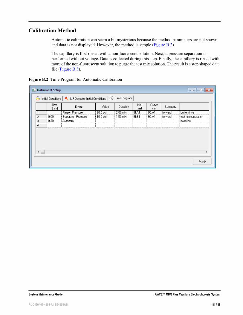
Calibration MethodAutomatic calibration can seem a bit mysterious because the method parameters are not shown and data is not displayed. However, the method is simple (Figure B.2).
The capillary is first rinsed with a nonfluorescent solution. Next, a pressure separation is performed without voltage. Data is collected during this step. Finally, the capillary is rinsed with more of the non-fluorescent solution to purge the test mix solution. The result is a step shaped data file (Figure B.3).
Figure B.2 Time Program for Automatic Calibration
System Maintenance Guide P/ACE™ MDQ Plus Capillary Electrophoresis System
RUO-IDV-05-4904-A | B54955AB 81 / 88

Calibration Results
Figure B.3 Representative Results from Automatic Calibration Using Method in Figure B.2
Non-fluorescent Solutions
Typically, the non-fluorescent solution used in the calibration is the separation buffer. Always be careful that this solution is safe for use in the type of capillary being used. For example, borate buffer should never be used for calibration of coated capillaries such as those used with IEF, carbohydrate, and single-stranded DNA separations. Another concern with buffers is possible interaction with fluorescein. When borate and fluorescein are mixed, the fluorescence increases for a short period of time. This causes a bump in the step data. To eliminate the bump, the fluorescein is mixed 1:1 with the buffer for the calibration mix. This mixture loses fluorescence after an hour or more and should be discarded. Water is almost always safe for capillaries and does not interact with fluorescein (do not need to mix 1:1 for test solution). An expected target response value for water/fluorescein calibration has not been established for the 75 µm i.d., 60 cm bare fused-silica capillary. (Water does not make such a good separation buffer).
P/ACE™ MDQ Plus Capillary Electrophoresis System System Maintenance Guide
82 / 88 RUO-IDV-05-4904-A | B54955AB

LIF Calibration for Other Capillaries
For detector performance tests, a 75 µm i.d., 60 cm total length bare fused-silica capillary is used. Many applications require capillaries with different dimensions. Capillary dimensions can affect the test mix calibration in two ways:
• For capillaries other than 60 cm long, the step change will occur at a different time. During automatic calibration, the software calculates this time based on the values entered in the LIF Calibration wizard.
• For capillaries with internal diameters other than 75 µm, the target values will be different. For a bare fused-silica capillary, this new target value can be calculated based on the 75 µm capillary target as shown in Figure B.4.
Figure B.4 Calculating the Target Value for a 50 µm i.d. Capillary
The LIF Calibration wizard requires an integer for a target value, so the target calculated above (for the 50 µm i.d. capillary) should be rounded to 15. This rounding is not a problem because RFU are arbitrary units. If the same number is used as the target, a given concentration should have the same response on any detector, capillary, or laser. Because the target is rounded down, it is likely the raw detector response is slightly higher than the target value. This causes the CCF to be slightly smaller than one. This does not have any affect on the sensitivity because the signal and the noise are corrected by the same CCF.
LIF Calibration for Different Fluorescent Solutions
A given application can require use of a fluorescent marker other than fluorescein. Depending on the marker, the emission wavelength can be significantly different than fluorescein; most likely different filters are required. With different filters, the standard fluorescein target is no longer valid. Even if fluorescein can be detected at the new wavelength, a new target value should be established. It can also be necessary to use the appropriate fluorescent solution for the application instead of fluorescein.
75 µm i.d. capillary cross-sectional area: = Pi * r2
= 3.14 * (75/2)2
= 4418
50 µm i.d. capillary cross-sectional area: = 3.14 * (50/2)2
= 1963
Area ratio: = 1963/4418= 0.44
50 µm target: = 0.44 * 75 µm target= 0.44 * 35 RFU= 15.4
System Maintenance Guide P/ACE™ MDQ Plus Capillary Electrophoresis System
RUO-IDV-05-4904-A | B54955AB 83 / 88

Establishing a new target value is simple:
• Use manual calibration to set the CCF to 1.0. • Run the pressure separation method described above six times. • Calculate the average response of the step change for the six runs. This value is the new target.
If an application requires a coated capillary, do not use a borate solution. Substituting water for the borate should be safe for most capillary coatings. When water is used in place of buffer, do not mix the fluorescein 1:1 with buffer or water. Inject the fluorescein without diluting it.
Standard System Performance Test
The standard calibration test uses borate buffer and a test mix solution of fluorescein mixed 1:1 with borate buffer. The mix of fluorescein with buffer is necessary to achieve a flat step change. Borate buffer is used because the system performance test uses an electrophoretic separation step. Water cannot be used for an electrophoretic separation.
Calibration MethodFor a 75 µm i.d., 60 cm bare fused-silica capillary, use the method as shown in Figure B.5.
Figure B.5 Time Program for System Performance Test
The rinse and separation vials contain borate and the inject vial contains a 1:1 mixture of fluorescein and buffer. A peak is detected at about 5 minutes. Optimize the integration so only the main peak and small contaminant peaks are detected. Annotate the peak with S/N (ASTM). On a calibrated instrument, the S/N (signal-to-noise ratio) should be greater than 10 000.
P/ACE™ MDQ Plus Capillary Electrophoresis System System Maintenance Guide
84 / 88 RUO-IDV-05-4904-A | B54955AB

Calibration Results
Figure B.6 Representative Results from System Performance Test Using Method in Figure B.5
If the suitability option has been selected in the instrument configuration, a pass/fail criteria can be programmed into the method. Suitability reports can only be generated as part of a sequence.
System Maintenance Guide P/ACE™ MDQ Plus Capillary Electrophoresis System
RUO-IDV-05-4904-A | B54955AB 85 / 88

Troubleshooting
Many variables can affect the quality of an LIF method. To simplify troubleshooting, it is necessary to isolate and verify the performance of each of these variables. Follow the steps in Figure B.7 to troubleshoot an LIF detector.
Figure B.7 LIF Performance Troubleshooting Flow Chart
P/ACE™ MDQ Plus Capillary Electrophoresis System System Maintenance Guide
86 / 88 RUO-IDV-05-4904-A | B54955AB

Contact Us
Customer Training
• In North America: [email protected]
• In Europe: [email protected]
• Outside the EU and North America, visit sciex.com/education for contact information.
Online Learning Center
• SCIEXUniversity
SCIEX Support
SCIEX and its representatives maintain a staff of fully-trained service and technical specialists located throughout the world. They can answer questions about the system or any technical issues that might arise. For more information, visit the SCIEX website at sciex.com or contact us in one of the following ways.
• sciex.com/contact-us
• sciex.com/request-support
CyberSecurity
For the latest guidance on cybersecurity for SCIEX products, visit sciex.com/productsecurity.
System Maintenance Guide P/ACE™ MDQ Plus Capillary Electrophoresis System
RUO-IDV-05-4904-A | B54955AB 87 / 88

Documentation
This version of the document supersedes all previous versions of this document.
To view this document electronically, Adobe Acrobat Reader is required. To download the latest version, go to https://get.adobe.com/reader.
To find software product documentation, refer to the release notes or software installation guide that comes with the software. Documentation for the hardware products can be found on the Customer Reference DVD that comes with the system or component.
For the latest versions of the documentation, visit the SCIEX website at sciex.com.
NOTE To request a free, printed version of this document, contact sciex.com/contact-us.
P/ACE™ MDQ Plus Capillary Electrophoresis System System Maintenance Guide
88 / 88 RUO-IDV-05-4904-A | B54955AB


![Capillary thermostatting in capillary electrophoresis · Capillary thermostatting in capillary electrophoresis ... 75 µm BF 3 Injection: ... 25-µm id BF 5 capillary. Voltage [kV]](https://static.documents.pub/doc/80x56/5c176ff509d3f27a578bf33a/capillary-thermostatting-in-capillary-electrophoresis-capillary-thermostatting.jpg)
