152
Packaged Rooftop Air Conditioners Voyager™ Cooling and Gas/Electric 12½–25 Tons, 60 Hz June 2015 RT-PRC028Y-EN Product Catalog

Packaged Rooftop Air Conditioners
Voyager™ Cooling and Gas/Electric
12½–25 Tons, 60 Hz
June 2015 RT-PRC028Y-EN
Product Catalog

Introduction
© 2015 Trane All rights reserved RT-PRC028Y-EN
Packaged Rooftop Air Conditioners
Through the years, Trane has designed and developed the most complete line of Packaged Rooftop products available in the market today. Trane was the first to introduce the Micro—microelectronic unit controls—and has continued to improve and revolutionize this design concept.
The ReliaTel™control platform offers the same great features and functionality as the original Micro, with additional benefits for greater application flexibility.
Voyager continues to provide the highest standards in quality and reliability, comfort, ease of service, and the performance of Trane light commercial products.
Trane customers demand products that provide exceptional reliability, meet stringent performance requirements, and are competitively priced. Trane delivers with Voyager.
Voyager features cutting edge technologies: reliable compressors, Trane engineered ReliaTel controls, computer-aided run testing, and Integrated Comfort™ Systems. So, whether you’re the contractor, the engineer, or the owner, you can be certain Voyager products are built to meet your needs.
Copyright
This document and the information in it are the property of Trane, and may not be used or reproduced in whole or in part without written permission. Trane reserves the right to revise this publication at any time, and to make changes to its content without obligation to notify any person of such revision or change.
Trademarks
Trane and the Trane logo, CompleteCoat, Frostat, Integrated Comfort Systems, ReliaTel, Tracer, Voyager, are trademarks of Trane in the United States and other countries. All trademarks referenced in this document are the trademarks of their respective owners.
Revision Summary
RT-PRC028Y-EN (26 June 2015)
• Added Horizontal Low Leak Economizer
• Updated Features & Benefits, Performance Data, Weights, and Mechanical Specifications

Table of Contents
RT-PRC028Y-EN 3
Features and Benefits . . . . . . . . . . . . . . . . . . . . . . . . . . . . . . . . . . . . . . . . . . . . . . . . . . . 4
Standard and Optional Features at a Glance . . . . . . . . . . . . . . . . . . . . . . . . . . . 4Standard Features . . . . . . . . . . . . . . . . . . . . . . . . . . . . . . . . . . . . . . . . . . . . . 4Factory Installed Options15 * . . . . . . . . . . . . . . . . . . . . . . . . . . . . . . . . . . . . 5Factory* or Field Installed Options15 . . . . . . . . . . . . . . . . . . . . . . . . . . . . . . 5Field Installed Options . . . . . . . . . . . . . . . . . . . . . . . . . . . . . . . . . . . . . . . . . 6Other Benefits . . . . . . . . . . . . . . . . . . . . . . . . . . . . . . . . . . . . . . . . . . . . . . . . 6
Outstanding Standard Features . . . . . . . . . . . . . . . . . . . . . . . . . . . . . . . . . . . . . . 7
Variety of Options . . . . . . . . . . . . . . . . . . . . . . . . . . . . . . . . . . . . . . . . . . . . . . . . . 10Factory Installed Options . . . . . . . . . . . . . . . . . . . . . . . . . . . . . . . . . . . . . . 10Factory or Field Installed Options . . . . . . . . . . . . . . . . . . . . . . . . . . . . . . . 14Field Installed Options . . . . . . . . . . . . . . . . . . . . . . . . . . . . . . . . . . . . . . . . 15
Other Benefits . . . . . . . . . . . . . . . . . . . . . . . . . . . . . . . . . . . . . . . . . . . . . . . . . . . . 17
Application Considerations . . . . . . . . . . . . . . . . . . . . . . . . . . . . . . . . . . . . . . . . . . . . . 20
Selection Procedure . . . . . . . . . . . . . . . . . . . . . . . . . . . . . . . . . . . . . . . . . . . . . . . . . . . 22Cooling Capacity . . . . . . . . . . . . . . . . . . . . . . . . . . . . . . . . . . . . . . . . . . . . . 22Heating Capacity . . . . . . . . . . . . . . . . . . . . . . . . . . . . . . . . . . . . . . . . . . . . . 23Air Delivery Selection . . . . . . . . . . . . . . . . . . . . . . . . . . . . . . . . . . . . . . . . . 23
Model Number Description . . . . . . . . . . . . . . . . . . . . . . . . . . . . . . . . . . . . . . . . . . . . . 24Model Number Notes . . . . . . . . . . . . . . . . . . . . . . . . . . . . . . . . . . . . . . . . . 25
General Data . . . . . . . . . . . . . . . . . . . . . . . . . . . . . . . . . . . . . . . . . . . . . . . . . . . . . . . . . . 26
Performance Data . . . . . . . . . . . . . . . . . . . . . . . . . . . . . . . . . . . . . . . . . . . . . . . . . . . . . 38
Controls . . . . . . . . . . . . . . . . . . . . . . . . . . . . . . . . . . . . . . . . . . . . . . . . . . . . . . . . . . . . . 106
Economizer Controls . . . . . . . . . . . . . . . . . . . . . . . . . . . . . . . . . . . . . . . . . . . . . 106
Zone Sensors . . . . . . . . . . . . . . . . . . . . . . . . . . . . . . . . . . . . . . . . . . . . . . . . . . . 106
Communication Interfaces . . . . . . . . . . . . . . . . . . . . . . . . . . . . . . . . . . . . . . . . 109
Electrical Data . . . . . . . . . . . . . . . . . . . . . . . . . . . . . . . . . . . . . . . . . . . . . . . . . . . . . . . . 110
Typical Wiring . . . . . . . . . . . . . . . . . . . . . . . . . . . . . . . . . . . . . . . . . . . . . . . . . . . . . . . . 122
Jobsite Connections . . . . . . . . . . . . . . . . . . . . . . . . . . . . . . . . . . . . . . . . . . . . . . . . . . 130
Dimensional Data . . . . . . . . . . . . . . . . . . . . . . . . . . . . . . . . . . . . . . . . . . . . . . . . . . . . . 131
Weights . . . . . . . . . . . . . . . . . . . . . . . . . . . . . . . . . . . . . . . . . . . . . . . . . . . . . . . . . . . . . 140
Mechanical Specifications . . . . . . . . . . . . . . . . . . . . . . . . . . . . . . . . . . . . . . . . . . . . . 143Factory Installed Options . . . . . . . . . . . . . . . . . . . . . . . . . . . . . . . . . . . . . 145Factory or Field Installed Options . . . . . . . . . . . . . . . . . . . . . . . . . . . . . . 147Field Installed Options . . . . . . . . . . . . . . . . . . . . . . . . . . . . . . . . . . . . . . . 149

Features and Benefits
Voyager has the features and benefits that make it first class in the light commercial rooftop market. Designed with input from field contractors and engineers, its U-shaped airflow performance is outstanding.
Standard and Optional Features at a Glance
Standard Features
• 2” throwaway filters• 5 year Limited Compressor Warranty• 5 year Limited Heat Exchanger (12½–17½ Tons); 1 Year on 20 and 25 Tons• 1 year Limited Parts Warranty• 3 Stages of Cooling Capability on 12½–20 Tons, 4 Stages of Cooling Capability on 25 Tons (High
Efficiency Units Only)• Anti-Short Cycle Timer• Belt Drive Motors• Colored and Numbered Wiring• Crankcase Heaters• Dedicated Airflow• Discharge Line Thermostat• Easy Access Low Voltage Terminal Board (LTB)• Foil-Faced and Edge Captured Insulation• High Efficiency Drum and Tube Heat Exchanger• High Efficiency Gas Heat with Hot Surface Ignition• High Pressure Cutout• IAQ Sloped Condensate Drain Pan• Liquid Line Refrigerant Drier• Low Ambient Cooling to 0°F• Microchannel Type Condenser Coils• Operating Charge of R-410A• Patented Hybrid Condenser Coil for Easy Cleaning
A
B
C
D
EF
H
I
G
Foil-Faced Insulation
Quick Adjust Idler Pulley
ReliaTel™ Microprocessor Controls
Colored and Numbered Wiring
Low Ambient Cooling to Zero° F
High and Low Pressure Switches
Scroll Compressors (R-410A)
Single Side Service
Smoke Detector
Fan Failure Switch
Clogged Filter Switch
Through-the-Base Gas Piping
Disconnect Switch or Circuit Breaker
Convenience Outlet
A
B
C
D
E
F
G
I
J
K
L
M
N
O
K
LM
J
N
O
Hinged Access DoorsH P Variable Frequency Drive
P
4 RT-PRC028Y-EN

Features and Benefits
• Phase Monitor• Provisions for Through-the-Base Gas and Condensate Drain Connections• Quick Access Panels• Quick Adjust Idler Arm Pulley• ReliaTel™Microprocessor Controls• Single Point Power• Single Side Service• Standardized Components• Thermal Expansion Valve14
• U-shaped Airflow Pattern• Variable Frequency Drive (Multispeed Indoor Fan, VAV, and Single Zone VAV)
Factory Installed Options15 *
• 2” MERV 8 or MERV 13 Pleated Filters6 with Filter Removal Tool• CO2 Sensor Wiring (Wiring Only)• Complete Coat™ Microchannel Condenser Coil• Condensate Overflow Switch• Dehumidification (Hot Gas Reheat)14
• Fault Detection Diagnostics (FDD)• High Efficiency Motors6
• High Short Circuit Current Rated (SCCR) Electrical Subsystem23, 24
• Hinged Access Doors• Human Interface - 5 inch Color Touchscreen• Modulating Gas Heat Furnace with a 2.5:1 Turndown Ratio2, 9
• Multi-Speed Indoor Fans• Multiple Zone Variable Air Volume (MZVAV)• Novar Return Air Sensor13, 19
• Novar Unit Controls16, 19
• Powered or Unpowered Convenience Outlet5
• Single Zone Variable Air Volume (SZ VAV)• Stainless Steel Drain Pan• Stainless Steel Heat Exchanger with 10 Year Warranty6
• Supply and/or Return Air Smoke Detector2, 10
• Through the Base Electrical Access12
• Through the Base Electrical with Circuit Breaker11, 12
• Through the Base Electrical with Disconnect Switch7, 11, 12
• Through the Base Gas Piping
Factory* or Field Installed Options15
• BACnet™ Communications Interface1
• Barometric Relief1
• Clogged Filter/Fan Failure Switch2, 6
• Discharge Air Temperature Sensing Kit2, 6
• Economizer - Standard, Downflow1
• Electric Heaters 6, 8, 12
• Frostat™2, 4, 6, 21
• Indoor Fan Motor Shaft Grounding Ring18
• LonTalk® Communications Interface (LCI)6
• Low Leak Economizer - Downflow• Oversized Motors6
• Reference or Comparative Enthalpy3, 6
RT-PRC028Y-EN 5

Features and Benefits
6 RT-PRC028Y-EN
• ReliaTel Options Module9
• Tool-less Hail Guards6
• Trane Communications Interface (TCI)6, 17
Field Installed Options
• CO2 Sensor• Digital Display Zone Sensor• Economizer - Standard, Horizontal• High and Low Static Drive Kits• Humidity Sensor• Low Leak Economizer - Downflow and Horizontal• LP Conversion Kit• Manual Outside Air Dampers• Motorized Outside Air Dampers• Powered Exhaust• Remote Potentiometer• Roof Curb (Downflow Only)• Thermostat• Ventilation Override Accessory2
• Wireless Zone Sensor• Zone Sensors and Remote Zone Sensors
Note: *Most Factory Installed Options (FIOPS) available for Downflow Air Discharge units only. Please verify with ordering system for availability.
Note: Explanation of Note1–Note20 located in “Model Number Description,” p. 24.
Other Benefits
• Cabinet Design Ensures Water Integrity• Ease of Service, Installation and Maintenance• Mixed Model Build Enables “Fastest in the Industry” Ship Cycle Times• Outstanding Airflow Distribution • ReliaTel Controls Benefits• Rigorous Testing• Unmatched Product Support• Varitrac

Features and Benefits
Outstanding Standard Features
Anti-Short Cycle Timer
Provides a 3 minute minimum “ON” time and 3 minute “OFF” time for compressors to enhance compressor reliability by assuring proper oil return.
Colored and Numbered Wiring
Save time and money tracing wires and diagnosing the unit.
Controls—ReliaTel™
ReliaTel microprocessor controls provide unit control for heating, cooling and ventilating utilizing input from sensors that measure indoor and outdoor temperature and other zone sensors. ReliaTel also provides outputs for building automation systems and expanded diagnostics. For a complete list of ReliaTel offerings, refer to “Other Benefits,” p. 17.
Conversionless Units
The dedicated design units (either downflow or horizontal) require no panel removal or alteration time to convert in the field — a major cost savings during installation. Horizontal units come complete with duct flanges so the contractor doesn’t have to field fabricate them. These duct flanges are a time and cost saver.
Crankcase Heaters
These band or insertion heaters provide improved compressor reliability by warming the oil to prevent migration during off-cycles or low ambient conditions. These are standard on all Voyager models.
Discharge Line Thermostat
A bi-metal element discharge line thermostats installed as a standard feature on the discharge line of each system. This standard feature provides extra protection to the compressors against high discharge temperatures in case of loss of charge, extremely high ambient and other conditions which could drive the discharge temperature higher.
Efficiencies
Standard or High Efficiency Cooling available.
CompressorsVoyager contains the best compressor technology available to achieve the highest possible performance. Dual compressors are outstanding for humidity control, light load cooling conditions and system back-up applications. Dual compressors are available on all models and allow for efficient cooling utilizing three stages of compressor operation (high efficiency 12½–20 Tons models only). 25 tons high efficiency units have 4 stages of cooling with a single compressor and tandem set (similar to variable speed).
RT-PRC028Y-EN 7

Features and Benefits
Trane requires the design to be tested to 2½ times this current standard. The drum and tube design has been tested and passed over 150,000 cycles, which is over 15 times the current ANSI cycling requirements. The negative pressure gas valve is used in the standard furnaces. This is one of our unique safety features. Modulating heaters use a pressure switch to ensure that the blower motor is operating before the gas valve is allowed to open.
The forced combustion blower supplies pre-mixed fuel through a single stainless steel burner screen into a sealed drum where ignition takes place. It is more reliable to operate and maintain than a multiple burner system. Modulating furnaces contain a metal fiber material to ensure proper flame distribution at low fire. The hot surface ignitor is a gas ignition device which doubles as a safety device utilizing a continuous test to prove the flame. The design is cycle tested at the factory for quality and reliability. Our gas/electric rooftops exceed all California seasonal efficiency requirements and perform even better than the California NOx emission requirements.
Low Ambient Cooling
All Voyager microprocessor units have cooling capabilities down to 0°F as standard.
Easy Access Low Voltage Terminal Board Foil Faced Insulation
Voyager’s Low Voltage Terminal Board is external to the electrical control cabinet. It is extremely easy to locate and attach the thermostat wire and test operation of all unit functions. This is another cost and time saving installation feature.
All panels in the evaporator section of the unit have cleanable foil-faced insulation. All edges are either captured or sealed to ensure no insulation fibers get into the airstream.
Heat Exchanger—Drum and Tube
The cabinet features a drum and tube heat exchanger (pictured right) that is manufactured using aluminized steel with stainless steel components for maximum durability.
The requirement for cycle testing of heat exchangers is 10,000 cycles by ANSI Z21.47. This is the standard required by both UL and AGA for cycle test requirements. Hot Surface Ignitor
Negative Pressure Gas Valve
Forced Combustion Blower
8 RT-PRC028Y-EN

Features and Benefits
Motors
All indoor fan motors are belt drive as standard.
Pressure Cutouts
Low and high pressure cutouts are standard on all Voyager models.
Phase Monitor
Voyager features a three-phase line monitor module that protects against phase loss, phase reversal and phase unbalance. It is intended to protect compressors from reverse rotation. It has an operating input voltage range of 190–600 Vac, and LED indicators for ON and FAULT. There are no field adjustments and the module will automatically reset from a fault condition.
Low Voltage Connections
The wiring of the low voltage connections to the unit and the zone sensors is as simple as 1-1, 2-2, and 3-3. This simplified system makes it easy for the installer to wire.
Microchannel Condenser CoilMicrochannel coils have better heat transfer performance due to flat streamlined tubes with small ports, and metallurgical tube-to-fin bond.
Microchannel condenser coil can reduce system refrigerant charge by up to 50% (potential LEED credit) because of smaller internal volume, which can lead to better compressor reliability. Compact all aluminum microchannel coils also help to reduce the unit weight. All-aluminum construction improves re-cyclability. Galvanic corrosion is also minimized due to all aluminum construction. Strong aluminum brazed structure provides better fin protection.
Quick-Access Panels
Remove three or more screws for access to the standardized internal components and wiring.
Quick-Adjust Slider Plate
With the Quick-Adjust Slider Plate (pictured right), the belt and sheaves can be quickly adjusted without moving the mounted fan motor. The result is a major savings in time and money.
Single Point Power
A single electrical connection powers the unit.
Single Side Service
Single side service is standard on all units.
Header (top removed)
Microchannel Flat Tube
Ribbon Fin
RT-PRC028Y-EN 9

Features and Benefits
Sloped Drain Pans
Every Voyager unit has a non-corrosive, sloped drain pan made of pre-painted steel and standard on all units.
Standardized Components
Components are placed in the same location on all Voyager units. Familiarize yourself with one Voyager and you are familiar with every Voyager. Due to standardized components throughout the Voyager line, contractors/owners can stock fewer parts.
U-Shaped Airflow Pattern
The U-shaped airflow allows for improved static capabilities.
Variable Frequency Drives - VFD (Multispeed Indoor Fan, VAV, and SZ VAV
Only)
Variable Frequency Drives are factory installed and tested to provide supply fan motor speed modulation. VFDs on the supply fan, as compared to inlet guide vanes or discharge dampers, are quieter, more efficient, and are eligible for utility rebates. All VFDs are designed to allow bypass if required. Bypass control will simply provide full nominal airflow in the event of drive failure. Bypass mode is indicated in the unit wiring manual. Modulating gas heat models with SZVAV allow tighter space temperature control with less temperature swing.
Variety of Options1
Factory Installed Options
CO2 Sensor Wiring
This is the unit wiring for field installed C02 sensors. Factory-installed C02 sensor wiring saves time and ensures proper unit connections for the field installed C02 sensor kits.
Complete Coat™ Condenser Coil
The cathodic epoxy type electrodisposition coating is formulated for high edge build to a number of different types of heat exchangers. The coating is selected to provide excellent resistance and durability to corrosive effects of alkalies, acids, alcohols, petroleum, seawater, salt air, and corrosive environments. This coating is available for microchannel coils only.
Circuit Breaker (Required with Through-the-Base Electrical)
This option is a factory installed thermal magnetic, molded case, HACR Circuit Breaker with provisions for through the base electrical connections. Available on all models.
Condensate Overflow Switch
A condensate overflow switch is available to shut the unit down in the event that the condensate drain line becomes clogged. This option protects the unit from water overflowing from the drain pan and entering the base of the units.
Dehumidification (Hot Gas Reheat)
This option allows for increased outdoor air ventilation. It reduces humidity levels while increasing comfort level in the air space. Cooling can operate without a demand for dehumidification. The hot gas reheat coil is designed to deliver maximum reheat temperature.
1 Refer to “Model Number Description,” p. 24 for option availability.
10 RT-PRC028Y-EN
Features and Benefits
Fault Detection & Diagnostics (FDD)
This offering meets the mandatory requirement of CA Title 24 of fully configurable diagnostics allowing fault history and reading fault codes at the unit.This option provides detection of the following faults: Air temperature sensor failure/fault and notification of acceptable economizer mode.The FDD system shall be certified by the Energy Commission as meeting the requirements.
High Efficiency Filtration
Voyager units offer a variety of high efficiency filtration options. MERV 8 and MERV 13 filters provide additional filtration beyond the capabilities of typical 2” throwaway filters. Also, when MERV 8 or MERV 13 filters are ordered, units come equipped with a filter removal tool.
High Efficiency Motors
High efficiency motors are available with efficiency ratings from 86.5 up to 91.0. It is not available for all models.
High Short Circuit Current Rating (SCCR)
Voyager rooftop units now have an optional high short circuit current rated electrical subsystem for units with an MOP above 60A. This option is a perfect fit for applications that need protection against high potential fault currents. This option also includes individual over current protection for each compressor and the indoor fan, as well as a dedicated over current protection to the condenser fan motor(s). When the high SCCR is ordered, the control box will have components separated into two sections - high and low voltage components.
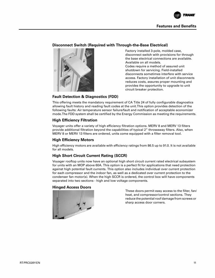
Disconnect Switch (Required with Through-the-Base Electrical)
Factory installed 3-pole, molded case, disconnect switch with provisions for through the base electrical connections are available. Available on all models.Codes require a method of assured unit shutdown for servicing. Field-installed disconnects sometimes interfere with service access. Factory installation of unit disconnects reduces costs, assures proper mounting and provides the opportunity to upgrade to unit circuit breaker protection.
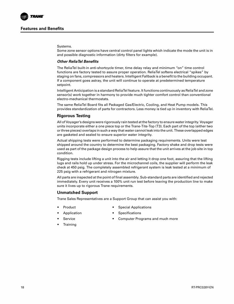
Hinged Access DoorsThese doors permit easy access to the filter, fan/heat, and compressor/control sections. They reduce the potential roof damage from screws or sharp access door corners.
RT-PRC028Y-EN 11

Features and Benefits
Modulating Gas Heat with a 2.5:1 Turndown Ratio
Upon receiving a call for heat, modulating gas heat units with a 2.5:1 turndown ratio light their burner at full fire (100%). After the burner is lit, the unit controls will monitor the discharge air temperature and modulate the input rate down to match the load.
Note: Modulating gas heat units are equipped with a stainless steel heat exchanger as standard.
Multi-Speed Indoor Fan System
Multi-speed indoor fan system is designed for use in applications for meeting the minimum requirement of CA Title 24. This system incorporates a multi-speed fan control to change the speed of the fan to 67% of full airflow based off compressor stages.
Multiple-Zone VAV Control
A multiple-zone VAV (MZVAV) system consists of a packaged rooftop unit that serves several individually controlled zones. Each zone is equipped with a VAV terminal unit that varies the quantity of air delivered to maintain the desired temperature in that zone. The rooftop unit controller varies the speed of the indoor fan to maintain the static pressure in the supply ductwork at a setpoint, ensuring that all zones receive the necessary quantity of air. In addition, cooling capacity is cycled to maintain the supply air temperature at the desired setpoint.
For decades, Trane has been an industry leader in rooftop VAV systems. Now, multiple-zone VAV control is available in Trane’s light commercial rooftop platform (3-25 tons).
Novar Unit Controls
Novar 3051 and 2024 are available for Voyager Cooling and Gas/Electric models.
Powered or Unpowered Convenience Outlet
This option is a GFCI, 120V/15amp, 2-plug, convenience outlet, either powered or unpowered. This option can only be ordered when Through the Base Electrical with either the Disconnect Switch or Circuit Breaker option is ordered. This option is available on all models.
Human Interface
The 5 inch Color Touchscreen Human Interface provides an intuitive user interface to the rooftop unit that speeds up unit commissioning, shortens unit troubleshooting times, and enhances preventative maintenance measures. The human interface includes several features such as:
• Data trending capabilities by means of time series graphs
• Historical alarm messages
• Real-time sensor measurements
• On board system setpoints
• USB port that enables the downloading of component runtime information as well as trended historical sensor data
• Customizable reports
12 RT-PRC028Y-EN

Features and Benefits
Single Zone VAV - One Zone Variable Air Volume Mode
Note: Single Zone VAV is designed to be used with a zone sensor. If a unit is configured for Single Zone VAV operation but is connected to a thermostat, the control will revert to multi-speed (2-Speed) indoor fan control. (See "Multi-Speed Indoor Fan System" above.)
Single zone VAV is designed for use in single zone applications like gymnasiums, auditoriums, manufacturing facilities, retail box stores, and any large open spaces, where there is a lot of diversity in the load profile. Single Zone VAV (SZ VAV) is an ideal replacement to "yesterday's" constant volume (CV) systems, by reducing operating costs while improving occupant comfort. SZ VAV systems combine Trane application, control and system integration knowledge to exactly match fan speed with cooling and heating loads, regardless of the operating condition. Trane algorithms meet/exceed ASHRAE 90.1- 2010, SZ VAV energy-saving recommendations, and those of CA Title 24. The result is an optimized balance between zone temperature control and system energy savings. Depending on your specific application, energy savings can be as much as 20%.
Note: Building system modeling in energy simulation software like TRACE is recommended to evaluate performance improvements for your application.
SZ VAV is fully integrated into the ReliaTel Control system and is available today. It provides the simplest and fastest commissioning in the industry through proven factory-installed, wired, and tested system controllers. All control modules, logic and sensors are factory installed, and tested to assure the highest quality and most reliable system available. This means no special programming of algorithms, or hunting at the jobsite for sensors, boards, etc. that need to be installed in the field. Single zone VAV is a quick and simple solution for many applications and is available from your most trusted rooftop VAV system solution provider- Trane.
Stainless Steel Drain Pan
For excellent corrosion and oxidation resistance, the optional stainless steel drain pan provides a cleanable surface that complement other IAQ solutions such as high efficiency filtration (MERV 8 or 13), demand control ventilation (CO2), and hot gas reheat.
Stainless Steel Heat Exchanger
The optional stainless steel heat exchanger is constructed of 304 stainless steel. It is resistant to corrosion and oxidation and easy to clean. The high strength to weight ratio allows for high ventilation rates with gas units and comes standard with a modulating gas heat option. With this option, a 10-year stainless steel heat exchanger warranty is standard.
Through-the-Base Electrical Utility Access
An electrical service entrance shall be provided allowing electrical access for both control and main power connections inside the curb and through the base of the unit. Option will allow for field installation of liquid-tight conduit and an external field installed disconnect switch.
Factory provided through the base openings simplify wiring and piping. Because these utility openings frequently minimize the number of roof penetrations, the integrity of roofing materials is enhanced.
Supply, Return, and Plenum Air Smoke Detector
With this option (pictured right) installed, if smoke is detected, all unit operation will be shut down. Reset will be manual at the unit. Return Air Smoke Detectors require minimum allowable airflow when used with certain models.
Supply and/or Return Smoke Detectors may not be used with the Plenum Smoke Detector.
RT-PRC028Y-EN 13

Features and Benefits
Factory or Field Installed Options1
BACnet™ Communications Interface
The BACnet communications interface allows the unit to communicate directly with a generic open protocol BACnet MS/TP Network Building Automation System Controls.
Barometric Relief
Designed to be used on downflow units, barometric relief is an unpowered means of relieving excess building pressure.
Clogged Filter/Fan Failure Switch
A dedicated differential pressure switch is available to achieve active fan failure indication and/or clogged filter indication. These sensors allow a zone sensor service light or Integrated Comfort System to indicate a dirty filter or a fan that’s not working. The field installation charges for these valuable feedback devices often eliminate them from consideration. Factory installation can make such features a good investment.
Discharge Air Temperature Sensing Kit
Provides true discharge air temperature sensing in heating models. The kit is functional only with the ReliaTel Options Module.
Economizer - Standard, Downflow
Economizers are equipped with either dry bulb, reference, or comparative enthalpy sensing. These economizers provide free cooling as the outdoor temperature and/or humidity decreases. Correctly installed, they offer a valuable energy savings. Factory-installed economizers save time and ensure proper installation.
Note: Factory-installed economizers require some field set-up.
Economizer - Low Leak, Downflow
This accessory meets low leak requirements for ASHRAE 90.1, IECC, and CA Title 24 standards (3 cfm/ft^2@1" wg exterior air, 4 cfm/ft^2@1" wg return air). This option allows 100% outdoor air supply from 0-100% modulating dampers and is standard with barometric relief. It can be paired with powered exhaust for additional building pressure relief. This option can be paired with or without Fault Detection & Diagnostics (FDD) to meet current mandatory CA Title 24 requirements. Available on downflow units only. The economizers come with three control options, dry bulb and reference or comparative enthalpy (optional).
Electric Heaters
Electric heat modules are available within the basic unit. If ordering the Through the Base Electrical option with an Electrical Heater, the heater must be factory installed.
Through-the-Base Gas Piping (Gas/Electric Only)
This option (pictured right) shall have all piping necessary including, black steel, manual gas shut-off valve, elbows, and union. This assembly will require minor field labor to install.
1 Refer to “Model Number Description,” p. 24 for option availability.
14 RT-PRC028Y-EN

Features and Benefits
Frostat™
This capillary bulb embedded in the face of the evaporator coil monitors coil temperature to prevent evaporator icing and protect the compressor. Recommended for applications with low leaving air temperatures, low airflow and/or high latent load applications.
Note: Frostat is standard on all Single-Zone VAV, Multiple-Zone VAV, and high efficiency units.
Indoor Fan Motor Shaft Grounding Ring
Shaft grounding rings are used on all VFD driven motors to provide a conductive discharge path away from the motor bearings to ground. Bearing Protection Rings shall be maintenance free circumferential rings of conductive micro fibers that discharge voltages to ground.
LonTalk® Communications Interface
The LonTalk communications interface allows the unit to communicate as a Tracer™LCI-V device or directly with generic LonTalk Network Building Automation System Controls.
Oversized Motors
Factory or field installed oversized motors are available for high static applications.
Reference or Comparative Enthalpy
Measures and communicates humidity while maximizing comfort control.
ReliaTel Options Module (RTOM)
The RTOM monitors the supply fan proving, clogged filter, supply air temperature, exhaust fan setpoint, dehumidification setpoint, supply air tempering, Frostat™ and smoke detector.
Note: The RTOM is standard on high efficiency units.
Field Installed Options1
CO2 Sensor - Demand Control Ventilation (DCV)
Demand-controlled ventilation (DCV) is a control strategy that responds to the actual demand (need) for ventilation by regulating the rate at which the HVAC system brings outdoor air into the building. A CO2 sensor measures the concentration (parts per million, ppm) of CO2 (Carbon Dioxide) in the air. As the CO2 concentration changes, the outside air damper modulates to meet the current ventilation needs of the zone. The CO2 sensor kit is available as a field installed accessory. Two field installed kits are offered; C02 sensor and wiring or C02 sensor only. The C02 sensor only kit should be ordered with factory installed C02 sensor wiring. Factory installed C02 sensor wiring saves set-up time and ensures proper unit connections for the C02 sensor.
Dampers
0–25 percent manual or 0–50 percent motorized outside air dampers are available.
Tool-less Hail Guards
Tool-less, hail protection quality coil guards (pictured right) shall be either factory or field-installed for condenser coil protection. This option protects the condenser coil from vandalism and/or hail damage.
Trane Communication Interface (TCI)
Available factory or field installed. This module when applied with the ReliaTel™ easily interfaces with Trane’s Integrated Comfort™ System.
1 Refer to “Model Number Description,” p. 24 for option availability.
RT-PRC028Y-EN 15

Features and Benefits
16 RT-PRC028Y-EN
Digital Display Zone Sensor
The Digital LCD (Liquid Crystal Display) zone sensor has the look and functionality of standard zone sensors.
Economizer - Standard, Horizontal
Economizers are equipped with either dry bulb or reference or comparative enthalpy sensing. These economizers provide free cooling as the outdoor temperature and/or humidity decreases. Correctly installed, they offer a valuable energy savings.
Economizer - Low Leak, Downflow & Horizontal
This accessory meets low leak requirements for ASHRAE 90.1, IECC, and CA Title 24 standards (3 cfm/ft^2@1" wg exterior air, 4 cfm/ft^2@1" wg return air). This option allows 100% outdoor air supply from 0-100% modulating dampers and is standard with barometric relief. It can be paired with powered exhaust for additional building pressure relief.
Humidity Sensor/Humidistat
Used in conjunction with our Dehumidification (Hot Gas Reheat) units to provide outstanding humidity control and comfort. Humidity sensors can be wall or duct mounted and set for levels between 40% and 60%.
LP Conversion Kit
Provided for field conversion of gas/electric units from natural gas to propane.
Powered Exhaust
This option is available on downflow units and provides exhaust of the return air, when using a downflow economizer, to maintain proper building pressurization. Great for relieving most building overpressurization problems.
Remote Potentiometer
When properly installed in the economizer control circuitry, this accessory provides a remote variable resistance to enable the operator to adjust the minimum damper position.
Roof Curbs
Available for downflow units. Only two roof curbs for the entire Voyager line simplifies curb selection.
Static Drive Accessories
Available on many models, this high and low static drive accessories extend the capability of the standard motor. Avoid expensive motors and operating costs by installing this optimized sheave accessory.
Ventilation Override Accessory
With the Ventilation Override Accessory installed, the unit can be set to transition to up to 3 different pre-programmed sequences for Smoke Purge, Pressurization and Exhaust. The transition occurs when a binary input on the RTOM is closed (shorted). This would typically be a hard wired relay output from a smoke detector or fire control panel. The ventilation override kit is available as a field installed accessory.
Wireless Zone Sensor
LCD display that provides heat, cool, auto, or off. Includes two temperature setpoints and a lockable setting with °F or °C indicators.
Zone Sensors/Thermostats
Available in programmable, automatic and manual styles.

Features and Benefits
Note: Zone sensors required for units configured for Single Zone VAV indoor fan system control to enable Single Zone VAV functionality.
Other Benefits
Cabinet Integrity
For added water integrity, Voyager has a raised 1-1/8” lip around the supply and return of the downflow units to prevent water from blowing into the ductwork.
Easy to Install, Service and Maintain
Because today’s owners are very cost-conscious when it comes to service and maintenance, Voyager was designed with direct input from service contractors. This valuable information helped to design a product that would get the serviceman off the job quicker and save the owner money. Voyager does this by offering outstanding standard features enhanced by a variety of factory and field installed options, multiple control options, rigorously tested proven designs and superior product and technical support.
Outstanding Airflow Distribution
Airflow is outstanding. The Voyager can replace an older machine with old ductwork and, in many cases, improve the comfort through better air distribution.
Voyager with ReliaTel reduces the number of components required to operate the unit, thereby reducing possibilities for component failure.
ReliaTel Makes Installing and Servicing Easy
ReliaTel eliminates the need for field installed anti-shortcycle timer and time delay relays.
ReliaTel controls provide these functions as an integral part of the unit. The contractor no longer has to purchase these controls as options and pay to install them. The wiring of the low voltage connections to the unit and the zone sensors is as easy as 1-1, 2-2, and 3-3. This simplified system makes wiring easier for the installer.
ReliaTel Makes Testing Easy
ReliaTel requires no special tools to run Voyager unit through its paces. Simply place a jumper between Test 1 and Test 2 terminals on the Low Voltage Terminal Board and the unit will walk through its operational steps automatically.
The unit automatically returns control to the zone sensor after stepping through the test mode a single time, even if the jumper is left on the unit.As long as the unit has power and the “system on” LED is lit, ReliaTel is operational. The light indicates that the controls are functioning properly.ReliaTel features expanded diagnostic capabilities when utilized with Trane Integrated Comfort™
ReliaTel™ Controls Benefits
ReliaTel controls provide unit control for heating, cooling and ventilating by utilizing input from sensors that measure outdoor and indoor temperature.
Quality and Reliability are enhanced through ReliaTel control and logic:
– Prevents the unit from short cycling, considerably improving compressor life.
– Ensures the compressor will run for a specific amount of time which allows oil to return for better lubrication, enhancing the reliability of the compressor.
RT-PRC028Y-EN 17
Features and Benefits
Systems.Some zone sensor options have central control panel lights which indicate the mode the unit is in and possible diagnostic information (dirty filters for example).
Other ReliaTel Benefits
The ReliaTel built-in anti-shortcycle timer, time delay relay and minimum “on” time control functions are factory tested to assure proper operation. ReliaTel softens electrical “spikes” by staging on fans, compressors and heaters. Intelligent Fallback is a benefit to the building occupant. If a component goes astray, the unit will continue to operate at predetermined temperature setpoint.
Intelligent Anticipation is a standard ReliaTel feature. It functions continuously as ReliaTel and zone sensor(s) work together in harmony to provide much tighter comfort control than conventional electro-mechanical thermostats.
The same ReliaTel Board fits all Packaged Gas/Electric, Cooling, and Heat Pump models. This provides standardization of parts for contractors. Less money is tied up in inventory with ReliaTel.
Rigorous Testing
All of Voyager’s designs were rigorously rain tested at the factory to ensure water integrity. Voyager units incorporate either a one piece top or the Trane-Tite-Top (T3). Each part of the top (either two or three pieces) overlaps in such a way that water cannot leak into the unit. These overlapped edges are gasketed and sealed to ensure superior water integrity.
Actual shipping tests were performed to determine packaging requirements. Units were test shipped around the country to determine the best packaging. Factory shake and drop tests were used as part of the package design process to help assure that the unit arrives at the job site in top condition.
Rigging tests include lifting a unit into the air and letting it drop one foot, assuring that the lifting lugs and rails hold up under stress. For the microchannel coils, the supplier will perform the leak check at 450 psig. The completely assembled refrigerant system is leak tested at a minimum of 225 psig with a refrigerant and nitrogen mixture.
All parts are inspected at the point of final assembly. Sub-standard parts are identified and rejected immediately. Every unit receives a 100% unit run test before leaving the production line to make sure it lives up to rigorous Trane requirements.
Unmatched Support
Trane Sales Representatives are a Support Group that can assist you with:
• Product • Special Applications
• Application • Specifications
• Service • Computer Programs and much more
• Training
18 RT-PRC028Y-EN

Features and Benefits
Note: VariTrac is for Voyager units with constant-speed indoor fan control. It is not recommended for use with Multiple-Speed Indoor Fan Control, Single-Zone VAV Control, or Multiple-Zone VAV Control.
VariTrac® – Changeover-Bypass SystemA changeover-bypass system consists of a packaged rooftop unit that serves several individually controlled zones. Each zone is equipped with a damper that varies the quantity of air delivered to maintain the desired temperature in that zone. However, unlike a conventional multiple-zone VAV system, the fan inside the rooftop unit operates at a constant speed. Any unneeded air is diverted to the return air stream through a bypass damper.
The term “changeover” refers to how this system handles the cooling and heating requirements of the building. The central rooftop unit can provide either cooled or heated air, and it makes this decision by periodically “polling” the zones.
RT-PRC028Y-EN 19

Application Considerations
Application of this product should be within the cataloged airflow and cooling considerations.
Barometric Relief
This product line offers an optional barometric relief damper for use in conjunction with economizer option. This accessory consists of gravity dampers which open with increased pressure. As the building air pressure increases, the pressure in the unit return air section also increases, opening the dampers and relieving the conditioned space.
Note: The effectiveness of barometric relief damper during economizing operation is limited, depending on the pressure drop of the return-air path. For some applications, powered exhaust may be better suited for preventing over-pressurization when economizing.
Clearance Requirements
The recommended clearances identified with unit dimensions should be maintained to ensure adequate serviceability, maximum capacity and peak operating efficiency. Actual clearances which appear inadequate should be reviewed with local Trane sales personnel.
Complete Coat™ Microchannel Condenser Coil
The cathodic epoxy type electrodisposition coating is formulated for high edge build to a number of different types of heat exchangers. The coating is selected to provide excellent resistance and durability to corrosive effects of alkalies, acids, alcohols, petroleum, seawater, salt air, and corrosive environments. This coating shall be available on microchannel condenser coils.
Condensate Trap
The evaporator is a draw-through configuration. A trap must be field provided prior to start-up on the cooling cycle.
Dual Compressors — 3 Stages of Cooling (12½–20 Tons)
Using the ReliaTel™ microprocessor controls, the Voyager™ high efficiency line can provide three stages of cooling, allowing for a more efficient and comfortable cooling operation.
Important: All high efficiency products will have intertwined evaporator coils as standard. No face split coils are allowed with 3 or 4 stages of cooling.
4 Stages of Cooling (25 Tons)
25 tons high efficiency units have 4 stages of cooling with a single compressor and tandem set (similar to variable speed).
Heating Operation
The heat exchanger is manufactured with aluminized steel. To prevent condensation within the heat exchanger, do not exceed 50 percent outside air or a minimum mixed air temperature of 40°F.
Optional Stainless Steel Heat Exchanger
The optional stainless steel heat exchanger is manufactured with 304 stainless steel. To prevent corrosion and prolong heat exchanger reliability, the minimum mixed air temperature allowed across the heat exchanger is 20°F. The stainless steel heat exchanger option is an excellent option that compliments the dehumidification package and is used in conjunction with the modulating heat option. Whenever high outside air or outside applications exist, these options should be utilized.
Low Ambient Cooling
The Voyager line features, with ReliaTel™ microprocessor controls, low ambient cooling down to 0°F. The following options need to be included/considered when low ambient applications are required: continuous fan operation, crankcase heaters (standard), thermal expansion valves,
20 RT-PRC028Y-EN

Application Considerations
frostat. Contact your local Trane Representative for more assistance with low ambient cooling applications.
Unit Pitch
These units have sloped condensate drain pans. Units must be installed level. Any unit slope must be toward access side of the unit.
Low Airflow
Unit applications designed for airflow below 320 cfm/ton are available on cooling only units and gas heat units equipped with modulating gas heat. Units must be high efficiency units with dehumidification (hot gas reheat) or TXV with Frostat and Crankcase heaters. Electric heat is restricted below 320 cfm/ton. Multi-speed or single zone VAV applications are capable of running below 320 cfm/ton during low speed airflow operation, but "full" airflow must be set to 320 cfm/ton or higher.
VariTrac®
VariTrac is for Voyager units with constant-speed indoor fan control. It is not recommended for use with Multiple-Speed Indoor Fan Control, Single-Zone VAV Control, or Multiple-Zone VAV Control.
RT-PRC028Y-EN 21

Selection Procedure
Cooling Capacity
Note: Cooling Capacity Procedure is the same for cooling (T*) and gas/electric (Y*).
Step 1.
Calculate the building’s total and sensible cooling loads at design conditions. Use the following calculation methods or any other standard accepted method. Factors used in unit selection:
Total Cooling Load: 180 MBh Sensible Cooling Load: 126 MBh Airflow: 6000 cfm Electrical Characteristics: 460/60/3Summer Design Conditions: Entering Evaporator Coil: 80 DB, 67 WB Outdoor Ambient: 95 DB External Static Pressure: 0.39 in. wgRooftop—downflow configuration Accessories
• Roof curb
• Economizer
• Electric Heat
Step 2.
As a starting point, a rough determination must be made of the size of the unit. The final selection will be made after examining the performance at the given conditions. Divide the total cooling load by nominal Btu/h per ton (12 MBh per ton); then round up to the nearest unit size.
180 MBh / 12 MBh = 15.0 tons
Step 3.
Table 14, p. 39 shows that a TSD180F4 has a gross cooling capacity of 186.1 MBh and 139.1 MBh sensible capacity at 6000 cfm and 95 DB outdoor ambient with 80 DB, 67 WB air entering the evaporator.
To Find Capacity at Intermediate Conditions Not in the Table.
When the design conditions are between two numbers that are in the capacity table, interpolation is required to approximate the capacity.
Note: Extrapolation outside of the table conditions is not recommended.
Step 4.
In order to select the correct unit which meets the building’s requirements, the fan motor heat must be deducted from the gross cooling capacity. The amount of heat that the fan motor generates is dependent on the effort by the motor—cfm and static pressure. To determine the total unit static pressure you add the external static pressure to the additional static related by the added features:
External Static Duct System 0.39 wg Note: The Evaporator Fan Performance Table 40, p. 74 has already accounted for the pressure drop for standard filters and wet coils (see note below Table 40). Therefore, the actual total static pressure is 0.56 - 0.06 (from Table 70, p. 101 = 0.50 wg).
Standard Filter 2 in. from Table 70, p. 101 0.06 wg
Economizer from Table 70, p. 101 (100% Return Air) 0.04 wg
Electric Heater Size 36 kW from Table 70, p. 101 0.07 wg
(Reference “Heating Capacity,” p. 23 for determination of heater size.) No additional static add for gas/heat exchanger.
Total Static Pressure 0.56 wg
22 RT-PRC028Y-EN

Selection Procedure
With 6000 cfm and 0.50 wg.Table 40, p. 74 shows 1.95 bhp for this unit. Note below the table gives a formula to calculate Fan Motor Heat,3.15 x bhp = MBh. 3.15 x 1.95 = 6.14 MBh.
Now subtract the fan motor heat from the gross cooling capacity of the unit: Net Total Cooling Capacity= 186.1 MBh - 6.14 = 179.96 MBh.
Net Sensible Cooling Capacity = 139.1 MBh - 6.14 = 132.96 MBh.
Step 5.
If the performance will not meet the required load of the building—total or sensible cooling load, try a selection at the next higher size unit.
Heating Capacity
Note: Heating capacity procedures DIFFER for cooling (T*) and gas/electric (Y*) units.
Step 1.
Calculate the building heating load.
Step 2.
Size the system heating capacity to match the calculated building heating load. The following are building heating requirements:
T* cooling units:460 volt/3 phase Power Supply Total heating load of 115.0 MBh 6000 cfm
The electric heat accessory capacities are listed in Table 72, p. 103. From the table, a 36 kW heater will deliver 122.94 MBh at 480 volts. In order to determine capacity at 460 volts, the heater voltage correction factor from Table 73, p. 104 must be used. Therefore, 122.94 MBh x .94 (voltage correction factor) = 115.6 MBh.
Y* gas/electric: Fuel natural gas total heating load of 195 MBh. Table Table 71, p. 103 shows 250 MBh and 350 MBh input models. The output capacities of these furnaces are 203 MBh and 284 MBh respectively. The low heat model with 203 MBh output best matches the building requirements.
Air Delivery Selection
Note: Air Delivery procedures is the same for cooling (T*) and gas/electric (Y*) units.
External static pressure drop through the air distribution system has been calculated to be 0.50 inches of water. From Table 70, p. 101 static pressure drop through the economizer is 0.04 and the 36 kW heater is 0.07 inches of water (0.39 + 0.04 + 0.07). Enter Table 40, p. 74 for a TSD180F4 at 6000 cfm and 0.50 static pressure. The standard motor at 585 rpm will give the desired airflow at a rated bhp of 1.95.
RT-PRC028Y-EN 23

0 G 3 R Z B 0 0
6 7 8 9 10 11 12 13
Model Number Description
Digit 1 — Unit TypeT = Packaged Cooling, Electric HeatY = Packaged Gas/Electric
Digit 2 — EfficiencyS = Standard EfficiencyH = High Efficiency
Digit 3 — Airflow ConfigurationD = DownflowH = Horizontal
Digit 4, 5, 6 — Nominal Gross Cooling Capacity (MBh)150 = 12½ Tons180 = 15 Tons210 = 17½ Tons240 = 20 Tons300 = 25 Tons
Digit 7 — Major Design SequenceF = Microchannel Type Condenser
CoilsG = ASHRAE 90.1-2013 (fan/
compressor staging)14
Digit 8 — Voltage Selection3 = 208-230/60/34 = 460/60/3W = 575/60/3K = 380/60/3
Digit 9 — Unit ControlsR = Reliatel
Digit 10 — Heating CapacityNote: (Applicable to Digit 1 T models
only)0 = No HeatG = 18 kW Electric HeatK = 27 kW Electric HeatN = 36 kW Electric HeatP = 54 kW Electric HeatR = 72 kW Electric Heat
Note: (Applicable to Digit 1 Y models only)
H = Gas Heat - HighL = Gas Heat - LowV = Gas Heat - SS Ht Ex - ModulatingX = Gas Heat - SS Ht Ex - LowZ = Gas Heat - SS Ht Ex - High
Digit 11 — Minor Design Sequence
Digit 12, 13 — Service Sequence00 = None01 = 18mm Microchannel Condenser
Coil
Note: ‘01’ only available on select models.
Y S D 1 5
1 2 3 4 5
24
Digit 14 — Fresh Air Selection0 = No Fresh AirD = Econ Dry Bulb w/ Barometric
Relief1F = Econ Reference Enthaply w/
Barometric Relief1H = Econ Comparative Enthaply w/
Barometric Relief1K = Low Leak Econ w/ Barometric
Relief1M = Low Leak Econ Reference
Enthalpy w/ Barometric Relief1 P = Low Leak Econ Comparative
Enthalpy w/ Barometric Relief1
Digit 15 — Supply Fan/Drive Type/Motor0 = Standard Motor1 = Oversized Motor6
3 = High Efficiency Motor6
6 = Single Zone Variable Air VolumeStandard Motor
7 = Multi-Speed Standard Motor8 = Single Zone Variable Air Volume
Oversized Motor9 = Multi-Speed Oversized MotorA = Single Zone Variable Air Volume
Standard Motor w/ ShaftGrounding Ring
B = Multi-Speed Standard Motor w/Shaft Grounding Ring
C = Single Zone Variable Air VolumeOversized Motor w/ ShaftGrounding Ring
D = Multi-Speed Oversized Motor w/Shaft Grounding Ring
E = VAV Supply Air TemperatureControl - Standard Motor
F = VAV Supply Air TemperatureControl - Oversized Motor
G = VAV Supply Air TemperatureControl - Standard Motor w/ ShaftGrounding Ring
H = VAV Supply Air TemperatureControl - Oversized Motor w/Shaft Grounding Ring
Digit 16 — Hinged Service Access / Filters0 = Standard Panels/Standard
Filters25
A = Hinged Access/Standard Filters25
B = Standard Panels/MERV 8 Filters6
C = Hinged Access/MERV 8 Filters6
D = Standard Panels/MERV 13 Filters6
E = Hinged Access/MERV 13 Filters6
Digit 17 — Condenser Coil Protection0 = Standard Coil1 = Standard Coil With Hail Guard4 = CompleteCoat™Condenser Coil
5 = CompleteCoat™Condenser Coilwith Hail Guard
Digit 18 — Through The Base ProvisionsNote: Applicable to Digit 1, T or Y models.0 = No Through The Base ProvisionsA = Through The Base Electric12
Note: Applicable to Digit1, Y models only.B = Through The Base GasC = Through The Base Electric/Gas12
D = Through The Base Access
Digit 19 — Disconnect Switch/Circuit Breaker11
0 = No Disconnect/circuit break1 = Unit Mounted Non-Fused
Disconnect Switch2 = Unit Mounted Circuit Breaker
Digit 20 — Convenience Outlet Option0 = Without Convenience OutletA = Unpowered Convenience Outlet5B = Powered Convenience Outlet5
Digit 21 — Communications Options0 = Without Communications Options1 = Trane Communications Interface6, 17
2 = Lontalk CommunicationsInterface6
3 = Novar 2024 Controls Interface19
4 = Novar 3051 Controls Interface19
5 = Novar 3051 CommunicationsInterface with Demand ControlVentilation19
6 = Building Automation ControlNetwork CommunicationsInterface
Digit 22 — Refrigeration System Option0 = Standard refrigeration systemB = Dehumidification (Hot Gas
Reheat)4,14
Digit 23 — Refrigeration Controls0 = Without Refrigeration Controls1 = Frostat9, 21
Digit 24 — Smoke Detector2,10
0 = Without Smoke DetectorA = Return Air Smoke DetectorB = Supply Air Smoke DetectorC = Return/Supply Air Smoke
DetectorD = Plenum Smoke Detector22
Digit 25 — System Monitoring Controls0 = No Monitoring Controls 1 = Clogged Filter Switch9
RT-PRC028Y-EN

Model Number Description
2 = Fan Failure Switch9
3 = Discharge Air Sensing9
4 = Clogged Filter Switch and FanFailure switch9
5 = Clogged Filter Switch andDischarge Air Sensing9
6 = Fan Failure Switch and DischargeAir Sensing9
7 = Clogged Filter Switch, Fan FailureSwitch and Discharge AirSensing9
8 = NOVAR Return Air Sensor (Novar2024)13,19
9 = NOVAR Zone Temp Sensor(Novar 3051)19
A = Condensate Drain Pan Overflow Switch
B = Clogged Filter Switch andCondensate Drain Pan OverflowSwitch9
C = Fan Failure Switch andCondensate Drain Pan OverflowSwitch9
D = Discharge Air Sensing andCondensate Drain Pan Overflow Switch9
E = Clogged Filter Switch, Fan Failure Switch and Condensate Drain Pan Overflow Switch9
F = Clogged Filter Switch, DischargeAir Sensing Tube and CondensateDrain Pan Overflow Switch9
G = Fan Failure Switch, Discharge AirSensing Tube and CondensateDrain Pan Overflow Switch9
H = Clogged Filter Switch, Fan Failure Switch, Discharge Air Sensingand Condensate Drain PanOverflow Switch9
Digit 26 - System Monitoring Controls0 = No Monitoring ControlsA = Demand Control Ventilation
(CO2)20
B = FDD (Fault Detection andDiagnostics)
C = FDD (Fault Detection Diagnostics)& Demand Control Ventilation(CO2)20
Digit 27 - Unit Hardware Enhancements0 = No Enhancements1 = Stainless Steel Drain Pan
Digit 28 - Short Circuit Current Rating0 = Standard SCCRA = 65kA SCCR Option23, 24
Digit 31 - Advanced Unit Controls0 = Standard Unit Controls1 = Human Interface26
Note: Most Factory Installed Options available for Downflow Air
RT-PRC028Y-EN
Discharge units only. Please verify with ordering system for availability.
Model Number Notes
1. Some field set up required.
2. Requires ReliaTel Options Module.
3. Requires Economizer.
4. All 22nd digit model numbers for reheat coil (B) require additional factory installed options: Frostat, and 2” pleated filters.
5. Must be ordered with Through-the-Base Electrical option or Horizontal-Side Access and either Unit Mounted Disconnect or Circuit Breaker.
6. Available factory installed on downflow AND horizontal units. Verify with ordering system.
7. Cannot be fused.
8. Must be factory installed when using Through-the-Base Options.
9. ReliaTel Options Module is required when ordering the following accessories: 4 Stage Cooling, Clogged Filter Switch, Fan Fail Switch, Condensate Overflow Switch, Discharge Air Sensing Kit, Frostat, Ventilation Override, Smoke Detector, Dehumidification and Modulating Gas Heat Furnace.
10. Option cannot be ordered in conjunction with field installed economizer on downflow units. Must be factory installed. The return air smoke detector may not fit up or work properly on the Voyager units when used in conjunction with 3rd party accessories (such as bolt on heat wheels, economizers, and power exhaust). Do not order the return air smoke detectors when using this type of accessory.
11. Unit mounted disconnect and circuit breakers are mutually exclusive of each other.
12. Through-the-base electrical option or Horizontal-Side Access must be ordered with either unit mounted disconnect or circuit
breaker. When adding heat, you must order Trane Electric Heat.
13. This option consists of the Novar return air sensor (Novar #WTS-10) that is wired and shipped in the return air section of the unit. The sensor ships with approximately 15’ of extra wire for dropping down the return air duct (downflow only).
14. Available on high efficiency units only.
15. All Factory Installed Options are Built-to-Order. Check order services for estimated production cycle.
16. The Novar control option includes the following factory installed and wired devices: Novar ETM-2024 or Novar 3051 rooftop controller, fan proving switch, clogged filter or unit shutdown switch, Cool 1, Cool 2, Heat switch and discharge air sensor (Novar 2024 is downflow only).
Note: Option cannot be ordered in conjunction with a factory installed smoke detector.
17. TCI is for use with non-VariTrac systems and VariTrac systems.
18. For use with multi-speed and SZVAV units only.
19. Novar is not available with SZ VAV products.
20. Demand Control Ventilation Option includes wiring only. The C02 sensor is a field-installed only option.
21. Frostat is standard on VAV and high efficiency units.
22. Supply and/or return smoke detector may not be used with the plenum smoke detector.
23. Only available where MOP is above 60A.
24. 575 VAC option is 25kA.
25. Standard filters are not available with Low Leak Economizers.
26. Human Interface is standard with FDD (Fault Detection Diagnostics).
25

General Data
Table 1. General data—cooling 12½–15 tons standard efficiency
12½ Tons Downflow & Horizontal Units 15 Tons Downflow & Horizontal UnitsTS*150F3,4,W,K YS*150F3,4,W,K TS*180F3,4,W,K YS*180F3,4,W,K
Cooling Performance(a)
Gross Cooling Capacity 150,000 150,000 186,000 186,000EER (Downflow/Horizontal)(b) 11 11 11 11Nominal Airflow CFM / ARI Rated CFM 5,000 / 4,400 5,000 / 4,400 6,000 / 5,300 6,000 / 5,300ARI Net Cooling Capacity 140,000 140,000 176,000 176,000 Integrated Energy Efficiency Ratio (IEER) (One Speed Fan / Multi or Variable Speed Fan)(c) 12.2/13.5 12.2/13.5 12.2/13.2 12.2/13.2
Percent Capacity @ part load (Stage 1/Stage 2) 55/100 55/100 68/100 68/100
System Power (kW) 12.73 12.73 16.00 16.00CompressorNumber/Type 2 / Scrolls 2 / Scrolls 2 / Scrolls 2 / ScrollsSoundOutdoor Sound Rating (BELS)(d) 9.2 9.2 9.2 9.2Outdoor CoilType Microchannel Microchannel Microchannel MicrochannelCoil Width (in.) 0.71 0.71 0.71/1.0 0.71Face Area (sq. ft.) 25.9 25.9 35.2 35.2Rows/FPI 1/23 1/23 1/23 / 1/20 1/23Indoor CoilType Hi-Performance Hi-Performance Hi-Performance Hi-PerformanceTube Size (in.) ID 0.3125 0.3125 0.3125 0.3125Face Area (sq. ft.) 17.50 17.50 26.00 26.00 Rows/FPI 3 / 15 3 / 15 3 / 15 3 / 15Refrigerant Control Short Orifice Short Orifice Short Orifice Short OrificeDrain Connection Number/Size (in.) 1/1.00 NPT 1/1.00 NPT 1/1.00 NPT 1/1.00 NPTOutdoor FanType Propeller Propeller Propeller PropellerNumber Used/Diameter (in.) 2 / 26 2 / 26 2 / 26 2 / 26Drive Type/No. Speeds Direct / 1 Direct / 1 Direct / 1 Direct / 1cfm 11,000 11,000 11,000 11,000 Number Motors/hp 2 / 0.50 2 / 0.50 2 / 0.50 2 / 0.50Motor rpm 1,100 1,100 1,100 1,100 Indoor FanType FC Centrifugal FC Centrifugal FC Centrifugal FC CentrifugalNumber Used/Diameter (in.) 1 / 15x15 1 / 15x15 1 / 18x18 1 / 18x18Drive Type/No. Speeds Belt / 1 Belt / 1 Belt / 1 Belt / 1Number Motors 1 1 1 1Motor hp (Standard/Oversized)(e) 3.0 / 5.0 3.0 / 5.0 3.0 / 5.0 3.0 / 5.0Motor rpm (Standard/Oversized) 1,740 / 3,450 1,740 / 3,450 1,740 / 3,450 1,740 / 3,450Motor Frame Size (Standard/Oversized) 145T / 145T 145T / 145T 145T / 145T 145T / 145T
26 RT-PRC028Y-EN

General Data
FiltersType Furnished(f) Throwaway Throwaway Throwaway ThrowawayNumber Size Recommended
Downflow (2)20x20x2 (4)20x25x2
(2)20x20x2 (4)20x25x2
(4)20x20x2 (4)20x25x2
(4)20x20x2 (4)20x25x2
Horizontal (2)20x20x2 (4)20x25x2
(2)20x20x2 (4)20x25x2 (8)20x25x2 (8)20x25x2
Refrigerant Charge (Pounds of R-410A)(g)
25mm Coil: Cir#1 / Cir#218mm Coil: Cir#1 / Cir#2
6.25/5.856.6/6.2
6.25/5.856.6/6.2
11.4 / 6.0 11.4 / 6.0
(a)Cooling Performance is rated at 95°F ambient, 80°F entering dry bulb, 67°F entering wet bulb. Gross capacity does not include the effect of fan motor heat. ARI capacity is net and includes the effect of fan motor heat. Units are suitable for operation to ±20% of nominal cfm. Certified in accordance with the Unitary Large Equipment Certification Program, which is based on ARI Standard 340/360.
(b)EER is rated at ARI conditions and in accordance with ARI Standard 210/240 or 340/360.(c) Integrated Energy Efficiency Ratio (IEER) is rated in accordance with AHRI standard 210/240 or 340/360.(d)Outdoor Sound Rating shown is tested in accordance with ARI Standard 270 or 370.(e)For 380V/60Hz units, the oversized motor (Indoor Fan) is used as the standard motor. Refer to oversized motor data.(f) An optional 2-inch pleated filter is also available.(g)Refrigerant charge is an approximate value. For a more precise value, see unit nameplate and service instructions.* Indicates both downflow and horizontal units.
Table 1. General data—cooling 12½–15 tons standard efficiency
12½ Tons Downflow & Horizontal Units 15 Tons Downflow & Horizontal UnitsTS*150F3,4,W,K YS*150F3,4,W,K TS*180F3,4,W,K YS*180F3,4,W,K
Table 2. General data—heating—12½–15 tons standard efficiency
12½ Tons Downflow & Horizontal Units 15 Tons Downflow & Horizontal Units
Heating Performance(a)(Gas/Electric Only)
Heating Models Low High
Modulating Turn Down
= 2.5:1 Low High
Modulating Turn Down
= 2.5:1
Heating Input (Btu/h) 150,000 250,000 350,000 250,000 350,000 350,000
1st Stage (Btu) 100,000 175,000 70,000 175,000 250,000 70,000
Heating Output (Btu/h) 122,000 203,000 283,500 203,000 284,000 283,500
1st Stage (Btu) 81,000 142,000 56,700 142,000 203,000 56,700
AFUE% (DF/HF)(b)
Downflow/Horizontal 81.0/81.0 80.7/79.9 80.1/79.1 80.7/79.9 80.1/79.1 80.1/79.1
Steady State Efficiency% 81.0 81.0 81.0 81.0 81.0 81.0
No. Burners 1 1 1 1 1 1
No. Stages 2 2 N/A 2 2 N/A
Gas Supply Line Pressure (in. wc) 2.5/14.0 2.5/14.0 2.5/14.0 2.5/14.0 2.5/14.0 2.5/14.0
Natural or LP (minimum/maximum) Natural or LP Natural or LP Natural Only Natural or LP Natural or LP Natural Only
Gas Connection Pipe Size (in.) 1/2 1/2 3/4 1/2 3/4 3/4
(a) Heating Performance limit settings and rating data were established and approved under laboratory test conditions using American National Standards Institute standards. Ratings shown are for elevations up to 2000 feet. For elevations above 2000 feet, ratings should be reduced at the rate of 4% for each 1000 feet above sea level.
(b) AFUE is rated in accordance with DOE test procedures.
RT-PRC028Y-EN 27

General Data
Table 3. General data—17½–20 tons standard efficiency
17½ Tons Downflow & Horizontal Units 20 Tons Downflow & Horizontal UnitsTS*210F3,4,W,K YS*210F3,4,W,K TS*240F3,4,W,K YS*240F3,4,W,K
Cooling Performance(a)
Gross Cooling Capacity 210,000 210,000 259,000 259,000EER (Downflow/Horizontal)(b) 11 11 10 10Nominal Airflow CFM / ARI Rated CFM 7,000 / 6,125 7,000 / 6,125 8,000 / 7,000 8,000 / 7,000ARI Net Cooling Capacity 196,000 196,000 240,000 240,000 Integrated Energy Efficiency Ratio (IEER) (One Speed Fan / Multi or Variable Speed Fan)(c) 11.8/12.9 11.8/12.9 11.5/12.3 11.5/12.3
Percent Capacity @ part load (Stage 1/Stage 2) 73/100 73/100 66/100 66/100
System Power (kW) 17.82 17.82 24.00 24.00CompressorNumber/Type 2 / Scrolls 2 / Scrolls 2 / Scrolls 2 / ScrollsSoundOutdoor Sound Rating (BELS)(d) 9.4 9.4 9.4 9.4Outdoor CoilType Microchannel Microchannel Microchannel MicrochannelCoil Width (in.) 0.71/1.0 0.71/1.0 1.0 1.0Face Area (sq. ft.) 35.2 35.2 35.2 35.2Rows/FPI 1/23 / 1/20 1/23 / 1/20 1 / 20 1 / 20Indoor CoilType Hi-Performance Hi-Performance Hi-Performance Hi-PerformanceTube Size (in.) ID 0.3125 0.3125 0.3125 0.3125Face Area (sq. ft.) 26.00 26.00 26.00 26.00 Rows/FPI 4 / 15 4 / 15 4 / 15 4 / 15Refrigerant Control Short Orifice Short Orifice Short Orifice Short OrificeDrain Connection Number/Size (in.) 1/1.00 NPT 1/1.00 NPT 1/1.00 NPT 1/1.00 NPTOutdoor FanType Propeller Propeller Propeller PropellerNumber Used/Diameter (in.) 2 / 26 2 / 26 2 / 26 2 / 26Drive Type/No. Speeds Direct / 1 Direct / 1 Direct / 1 Direct / 1cfm 14,500 14,500 15,500 15,500Number Motors/hp 2 / 1.0 2 / 1.0 2 / 1.0 2 / 1.0Motor rpm 1125 1125 1125 1125Indoor FanType FC Centrifugal FC Centrifugal FC Centrifugal FC CentrifugalNumber Used/Diameter (in.) 1 / 18x18 1 / 18x18 1 / 18x18 1 / 18x18Drive Type/No. Speeds Belt / 1 Belt / 1 Belt / 1 Belt / 1Number Motors 1 1 1 1Motor hp (Standard/Oversized)(e) 5.0 / 7.5 5.0 / 7.5 5.0 / 7.5 5.0 / 7.5Motor rpm (Standard/Oversized) 3,450 / 3,470 3,450 / 3,470 3,450 / 3,470 3,450 / 3,470Motor Frame Size (Standard/Oversized) 145T / 184T 145T / 184T 145T / 184T 145T / 184T
28 RT-PRC028Y-EN

General Data
FiltersType Furnished(f) Throwaway Throwaway Throwaway ThrowawayNumber Size Recommended
Downflow (4)20x20x2 (4)20x25x2
(4)20x20x2 (4)20x25x2
(4)20x20x2 (4)20x25x2
(4)20x20x2 (4)20x25x2
Horizontal (8)20x25x2 (8)20x25x2 (8)20x25x2 (8)20x25x2Refrigerant Charge (Pounds of R-410A)Downflow & Horizontal (Cir#1/Cir#2) 14.4 / 7.4 14.4 / 7.4 13.5 / 7 13.5 / 7
(a)Cooling Performance is rated at 95°F ambient, 80°F entering dry bulb, 67°F entering wet bulb. Gross capacity does not include the effect of fan motor heat. ARI capacity is net and includes the effect of fan motor heat. Units are suitable for operation to ±20% of nominal cfm. Certified in accordance with the Unitary Large Equipment Certification Program, which is based on ARI Standard 340/360.
(b)EER is rated at ARI conditions and in accordance with ARI Standard 210/240 or 340/360.(c) Integrated Energy Efficiency Ratio (IEER) is rated in accordance with AHRI standard 210/240 or 340/360.(d)Outdoor Sound Rating shown is tested in accordance with ARI Standard 270 or 370.(e)For 380V/60Hz units, the oversized motor (Indoor Fan) is used as the standard motor. Refer to oversized motor data.(f) Refrigerant charge is an approximate value. For a more precise value, see unit nameplate and service instructions.* Indicates both downflow and horizontal units.
Table 3. General data—17½–20 tons standard efficiency (continued)
17½ Tons Downflow & Horizontal Units 20 Tons Downflow & Horizontal UnitsTS*210F3,4,W,K YS*210F3,4,W,K TS*240F3,4,W,K YS*240F3,4,W,K
Table 4. General data—heating—17½–20 tons standard efficiency
17½ Tons Downflow & Horizontal Units 20 Tons Downflow & Horizontal Units
Heating Performance(a) (Gas/Electric Only)
Heating Models Low High
Modulating Turn
Down = 2.5:1 Low High
Modulating Turn
Down = 2.5:1
Heating Input (Btu/h) 250,000 350,000 350,000 250,000 400,000 350,000
1st Stage (Btu) 175,000 250,000 70,000 175,000 300,000 80,000
Heating Output (Btu/h) 203,000 284,000 283,500 203,000 324,000 283,500
1st Stage (Btu) 142,000 203,000 56,700 142,000 243,000 64,800
AFUE%(b)
Downflow/Horizontal 80.2/81.0 79.3/79.7 79.3/79.7 80.2/81.0 79.8/79.7 79.8/79.7
Steady State Efficiency% 81.0 81.0 81.0 81.0 81.0 81.0
No. Burners 1 1 1 1 1 1
No. Stages 2 2 N/A 2 2 N/A
Gas Supply Line Pressure (in. wc) 2.5/14.0 2.5/14.0 2.5/14.0 2.5/14.0 2.5/14.0 2.5/14.0
Natural or LP (minimum/maximum) Natural or LP Natural or LP Natural Only Natural or LP Natural or LP Natural Only
Gas Connection Pipe Size (in.) 1/2 3/4 3/4 1/2 3/4 3/4
(a)Heating Performance limit settings and rating data were established and approved under laboratory test conditions using American National Standards Institute standards. Ratings shown are for elevations up to 2000 feet. For elevations above 2000 feet, ratings should be reduced at the rate of 4% for each 1000 feet above sea level.
(b)AFUE is rated in accordance with DOE test procedures.
RT-PRC028Y-EN 29
General Data
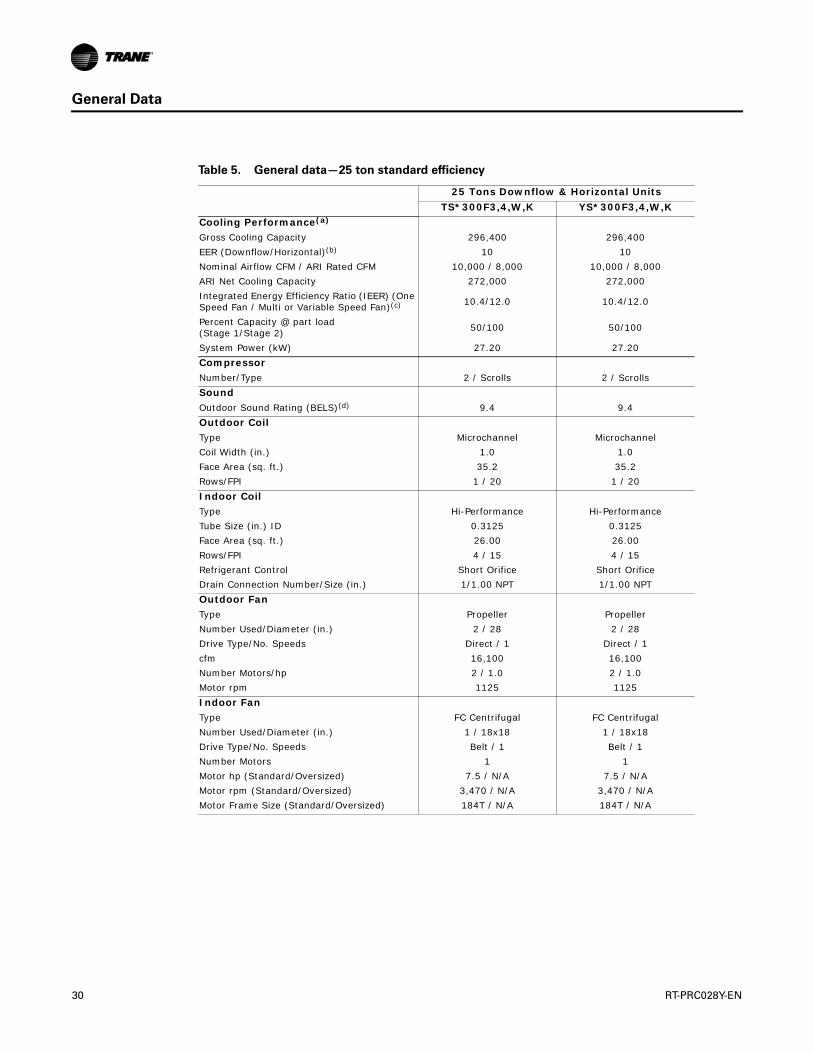
Table 5. General data—25 ton standard efficiency
25 Tons Downflow & Horizontal UnitsTS*300F3,4,W,K YS*300F3,4,W,K
Cooling Performance(a)
Gross Cooling Capacity 296,400 296,400EER (Downflow/Horizontal)(b) 10 10Nominal Airflow CFM / ARI Rated CFM 10,000 / 8,000 10,000 / 8,000ARI Net Cooling Capacity 272,000 272,000 Integrated Energy Efficiency Ratio (IEER) (One Speed Fan / Multi or Variable Speed Fan)(c) 10.4/12.0 10.4/12.0
Percent Capacity @ part load (Stage 1/Stage 2) 50/100 50/100
System Power (kW) 27.20 27.20 CompressorNumber/Type 2 / Scrolls 2 / ScrollsSoundOutdoor Sound Rating (BELS)(d) 9.4 9.4Outdoor CoilType Microchannel MicrochannelCoil Width (in.) 1.0 1.0Face Area (sq. ft.) 35.2 35.2Rows/FPI 1 / 20 1 / 20Indoor CoilType Hi-Performance Hi-PerformanceTube Size (in.) ID 0.3125 0.3125Face Area (sq. ft.) 26.00 26.00 Rows/FPI 4 / 15 4 / 15Refrigerant Control Short Orifice Short OrificeDrain Connection Number/Size (in.) 1/1.00 NPT 1/1.00 NPTOutdoor FanType Propeller PropellerNumber Used/Diameter (in.) 2 / 28 2 / 28Drive Type/No. Speeds Direct / 1 Direct / 1cfm 16,100 16,100Number Motors/hp 2 / 1.0 2 / 1.0Motor rpm 1125 1125Indoor FanType FC Centrifugal FC CentrifugalNumber Used/Diameter (in.) 1 / 18x18 1 / 18x18Drive Type/No. Speeds Belt / 1 Belt / 1Number Motors 1 1Motor hp (Standard/Oversized) 7.5 / N/A 7.5 / N/AMotor rpm (Standard/Oversized) 3,470 / N/A 3,470 / N/AMotor Frame Size (Standard/Oversized) 184T / N/A 184T / N/A
30 RT-PRC028Y-EN

General Data
FiltersType Furnished(e) Throwaway ThrowawayNumber Size RecommendedDownflow (4)20x20x2 (4)20x25x2 (4)20x20x2 (4)20x25x2Horizontal (8)20x25x2 (8)20x25x2Refrigerant Charge (Pounds of R-410A)(f)
Downflow & Horizontal (Cir#1/Cir#2) 10.5 / 10.5 10.5 / 10.5
(a)Cooling Performance is rated at 95°F ambient, 80°F entering dry bulb, 67°F entering wet bulb. Gross capacity does not include the effect of fan motor heat. ARI capacity is net and includes the effect of fan motor heat. Units are suitable for operation to ±20% of nominal cfm. Certified in accordance with the Unitary Large Equipment Certification Program, which is based on ARI Standard 340/360.
(b)EER is rated at ARI conditions and in accordance with ARI Standard 210/240 or 340/360.(c) Integrated Energy Efficiency Ratio (IEER) is rated in accordance with AHRI standard 210/240 or 340/360.(d)Outdoor Sound Rating shown is tested in accordance with ARI Standard 270 or 370.(e)An optional 2-inch pleated filter is also available.(f) Refrigerant charge is an approximate value. For a more precise value, see unit nameplate and service instruc-
tions.* Indicates both downflow and horizontal units.
Table 5. General data—25 ton standard efficiency (continued)
25 Tons Downflow & Horizontal UnitsTS*300F3,4,W,K YS*300F3,4,W,K
Table 6. General data—heating—25 tons
25 Tons Downflow & Horizontal Units
Heating Performance(a) (Gas/Electric Only)
Heating Models Low HighModulating Turn
Down = 2.5:1
Heating Input (Btu/h) 250,000 400,000 350,000
1st Stage (Btu) 175,000 300,000 80,000
Heating Output (Btu/h) 203,000 324,000 283,500
1st Stage (Btu) 142,000 243,000 64,800
AFUE%(b)
Downflow/Horizontal 80.2 / 81.0 79.8 / 79.7 79.8 / 79.7
Steady State Efficiency% 81.0 81.0 81.0
No. Burners 1 1 1
No. Stages 2 2 N/A
Gas Supply Line Pressure (in. wc) 2.5 / 14.0 2.5 / 14.0 2.5 / 14.0
Natural or LP (minimum/maximum) Natural or LP Natural or LP Natural Only
Gas Connection Pipe Size (in.) ½ ¾ ¾
(a)Heating Performance limit settings and rating data were established and approved under laboratory test conditions using American National Standards Institute standards. Ratings shown are for elevations up to 2000 feet. For elevations above 2000 feet, ratings should be reduced at the rate of 4% for each 1000 feet above sea level.
(b)AFUE is rated in accordance with DOE test procedures.
RT-PRC028Y-EN 31

General Data
Table 7. General data—12½–15 ton high efficiency
12½ Tons Downflow & Horizontal Units 15 Tons Downflow & Horizontal UnitsTH*150G3,4,W YH*150G3,4,W TH*180G3,4,W YH*180G3,4,W
Cooling Performance(a)
Gross Cooling Capacity 152,400 152,400 180,500 180,500EER(b) 12.1 12.1 12.1 12.1Nominal CFM / ARI Rated CFM 5,000 / 4,000 5,000 / 4,000 6,000 / 5,250 6,000 / 5,250ARI Net Cooling Capacity 144,000 144,000 174,000 174,000 Integrated Energy Efficiency Ratio (IEER) (One Speed Fan / Multi or Variable Speed Fan)(c) 13.5/15.0 13.5/15.0 14.0/15.0 14.0/15.0
Percent Capacity @ part load (Stage 1/Stage 2/Stage 3)(d) 30/70/100 30/70/100 32/68/100 32/68/100
System Power (kW) 11.90 11.90 14.38 14.38CompressorNumber/Type 2 / Scrolls 2 / Scrolls 2 / Scrolls 2 / ScrollsSoundOutdoor Sound Rating (BELS)(e) 9.2 9.2 9.2 9.2Outdoor CoilType Microchannel Microchannel Microchannel MicrochannelCoil Width (in.) 1.0 1.0 1.0 1.0Face Area (sq. ft.) 35.2 35.2 42.6 42.6Rows/FPI 1 / 20 1 / 20 1 / 20 1 / 20Indoor CoilType Hi-Performance Hi-Performance Hi-Performance Hi-PerformanceTube Size (in.) ID 0.3125 0.3125 0.3125 0.3125Face Area (sq. ft.) 26.00 26.00 31.42 31.42Rows/FPI 4 / 15 4 / 15 4 / 15 4 / 15Refrigerant Control TXV TXV TXV TXVDrain Connection Number/Size (in.) 1/1.00 NPT 1/1.00 NPT 1/1.00 NPT 1/1.00 NPTOutdoor FanType Propeller Propeller Propeller PropellerNumber Used/Diameter (in.) 2 / 26 2 / 26 2 / 26 2 / 26Drive Type/No. Speeds Direct / 1 Direct / 1 Direct / 1 Direct / 1cfm 11,400 11,400 11,700 11,700 Number Motors/hp 2 / 0.50 2 / 0.50 2 / 0.50 2 / 0.50Motor rpm 1,100 1,100 1,100 1,100 Indoor FanType FC Centrifugal FC Centrifugal FC Centrifugal FC CentrifugalNumber Used/Diameter (in.) 1 / 18x18 1 / 18x18 1 / 18x18 1 / 18x18Drive Type/No. Speeds Belt / 1 Belt / 1 Belt / 1 Belt / 1Number Motors 1 1 1 1Motor hp (Standard/Oversized) 3.0 / 5.0 3.0 / 5.0 3.0 / 5.0 3.0 / 5.0Motor rpm (Standard/Oversized) 1,740 / 3,450 1,740 / 3,450 1,740 / 3,450 1,740 / 3,450Motor Frame Size (Standard/Oversized) 145T / 145T 145T / 145T 145T / 145T 145T / 145T
32 RT-PRC028Y-EN

General Data
FiltersType Furnished(f) Throwaway Throwaway Throwaway ThrowawayNumber Size Recommended
Downflow (4)20x20x2 (4)20x25x2 (4)20x20x2 (4)20x25x2 (8)20x20x2 (4)20x16x2
(8)20x20x2 (4)20x16x2
Horizontal (8)20x25x2 (8)20x25x2 (12)20x20x2 (12)20x20x2Refrigerant Charge (Pounds of R-410A) (g)
Downflow & Horizontal (Cir#1/Cir#2) 12.5/7.1 12.5/7.1 13.0/8.5 13.0/8.5Optional Hot Gas Reheat Coil (Cir#1/Cir#2) 9.2 / 6.9 9.2 / 6.9 10.9 / 8.9 10.9 / 8.9
(a)Cooling Performance is rated at 95°F ambient, 80°F entering dry bulb, 67°F entering wet bulb. Gross capacity does not include the effect of fan motor heat. ARI capacity is net and includes the effect of fan motor heat. Units are suitable for operation to ±20% of nominal cfm. Certified in accordance with the Unitary Large Equipment Certification Program, which is based on ARI Standard 340/360.
(b)EER is rated at ARI conditions and in accordance with ARI Standard 210/240 or 340/360.(c) Integrated Energy Efficiency Ratio (IEER) is rated in accordance with AHRI standard 210/240 or 340/360.(d)3 stages not available with Reheat models.(e)Outdoor Sound Rating shown is tested in accordance with ARI Standard 270 or 370.(f) An optional 2 inch pleated filter is also available.(g)Refrigerant charge is an approximate value. For a more precise value, see unit nameplate and service instructions.* Indicates both downflow and horizontal units.
Table 7. General data—12½–15 ton high efficiency
12½ Tons Downflow & Horizontal Units 15 Tons Downflow & Horizontal UnitsTH*150G3,4,W YH*150G3,4,W TH*180G3,4,W YH*180G3,4,W
Table 8. General data—heating—12½-15 ton high efficiency
12½ Tons Downflow & Horizontal Units 15 Tons Downflow & Horizontal UnitsHeating Performance(a) (Gas/Electric Only)
Heating Models Low High
Modulating Turn Down
= 2.5:1 Low High
Modulating Turn Down
= 2.5:1Heating Input (Btu/h) 150,000 250,000 350,000 250,000 350,000 350,0001st Stage (Btu) 100,000 175,000 70,000 175,000 250,000 70,000Heating Output (Btu/h) 122,000 203,000 283,500 203,000 284,000 283,5001st Stage (Btu) 81,000 142,000 56,700 142,000 203,000 56,700AFUE% (DF/HF)(b)
Downflow/Horizontal 81.0 / 81.0 80.7 / 79.9 80.1 / 79.1 81.7 / 79.9 80.1 / 79.1 80.1 / 79.1Steady State Efficiency% 81 81 81 81 81 81No. Burners 1 1 1 1 1 1No. Stages 2 2 N/A 2 2 N/AGas Supply Line Pressure (in. wc) 2.5 / 14.0 2.5 / 14.0 2.5 / 14.0 2.5 / 14.0 2.5 / 14.0 2.5 / 14.0Natural or LP (minimum/maximum) Natural Only Natural OnlyGas Connection Pipe Size (in.) ½ ½ ¾ ½ ¾ ¾
(a)Heating Performance limit settings and rating data were established and approved under laboratory test conditions using American National Standards Institute standards. Ratings shown are for elevations up to 2000 feet. For elevations above 2000 feet, ratings should be reduced at the rate of 4% for each 1000 feet above sea level.
(b)AFUE is rated in accordance with DOE test procedures.
RT-PRC028Y-EN 33

General Data
Table 9. General data—17½–20 ton high efficiency
17½ Tons Downflow & Horizontal Units 20 Tons Downflow & Horizontal UnitsTH*210G3,4,W YH*210G3,4,W TH*240G3,4,W YH*240G3,4,W
Cooling Performance(a)
Gross Cooling Capacity 214,800 214,800 248,500 248,500EER(b) 11.8 11.8 11.0 11.0Nominal CFM / ARI Rated CFM 7,000 / 5,600 7,000 / 5,600 8,000 / 6,400 8,000 / 6,400ARI Net Cooling Capacity 204,000 204,000 234,000 234,000 Integrated Energy Efficiency Ratio (IEER) (One Speed Fan / Multi or Variable Speed Fan)(c) 13.0/14.0 13.0/14.0 12.4/14.0 12.4/14.0
Percent Capacity @ part load (Stage 1/Stage 2/Stage 3)(d) 31/69/100 31/69/100 30/70/100 30/70/100
System Power (kW) 17.29 17.29 21.27 21.27 CompressorNumber/Type 2 / Scrolls 2 / Scrolls 2 / Scrolls 2 / ScrollsSoundOutdoor Sound Rating (BELS)(e) 9.2 9.2 9.4 9.4Outdoor CoilType Microchannel Microchannel Microchannel MicrochannelCoil Width (in.) 1.0 1.0 1.0 1.0Face Area (sq. ft.) 42.6 42.6 42.6 42.6Rows/FPI 1 / 20 1 / 20 1 / 20 1 / 20Indoor CoilType Hi-Performance Hi-Performance Hi-Performance Hi-PerformanceTube Size (in.) ID 0.3125 0.3125 0.3125 0.3125Face Area (sq. ft.) 31.42 31.42 31.42 31.42 Rows/FPI 4 / 15 4 / 15 4 / 15 4 / 15Refrigerant Control TXV TXV TXV TXVDrain Connection Number/Size (in.) 1/1.00 NPT 1/1.00 NPT 1/1.00 NPT 1/1.00 NPTOutdoor FanType Propeller Propeller Propeller PropellerNumber Used/Diameter (in.) 2 / 26 2 / 26 2 / 28 2 / 28Drive Type/No. Speeds Direct / 1 Direct / 1 Direct / 1 Direct / 1cfm 15,800 15,800 16,500 16,500 Number Motors/hp 2 / 1.0 2 / 1.0 2 / 1.0 2 / 1.0Motor rpm 1,125 1,125 1,125 1,125 Indoor FanType FC Centrifugal FC Centrifugal FC Centrifugal FC CentrifugalNumber Used/Diameter (in.) 1 / 18x18 1 / 18x18 1 / 18x18 1 / 18x18Drive Type/No. Speeds Belt / 1 Belt / 1 Belt / 1 Belt / 1Number Motors 1 1 1 1Motor hp (Standard/Oversized) 5.0 / 7.5 5.0 / 7.5 5.0 / 7.5 5.0 / 7.5Motor rpm (Standard/Oversized) 3,450 / 3,470 3,450 / 3,470 3,450 / 3,470 3,450 / 3,470Motor Frame Size (Standard/Oversized) 145T / 184T 145T / 184T 145T / 184T 145T / 184T
34 RT-PRC028Y-EN
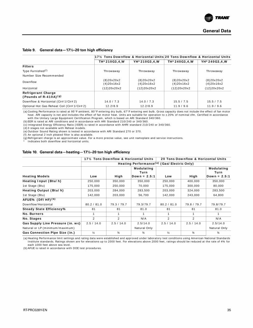
General Data
FiltersType Furnished(f) Throwaway Throwaway Throwaway ThrowawayNumber Size Recommended
Downflow (8)20x20x2 (4)20x16x2
(8)20x20x2 (4)20x16x2
(8)20x20x2 (4)20x16x2
(8)20x20x2 (4)20x16x2
Horizontal (12)20x20x2 (12)20x20x2 (12)20x20x2 (12)20x20x2Refrigerant Charge (Pounds of R-410A)(g)
Downflow & Horizontal (Cir#1/Cir#2) 14.0 / 7.3 14.0 / 7.3 15.5 / 7.5 15.5 / 7.5Optional Hot Gas Reheat Coil (Cir#1/Cir#2) 12.2/8.9 12.2/8.9 11.9 / 9.6 11.9 / 9.6
(a)Cooling Performance is rated at 95°F ambient, 80°F entering dry bulb, 67°F entering wet bulb. Gross capacity does not include the effect of fan motor heat. ARI capacity is net and includes the effect of fan motor heat. Units are suitable for operation to ±20% of nominal cfm. Certified in accordance with the Unitary Large Equipment Certification Program, which is based on ARI Standard 340/360.
(b)EER is rated at ARI conditions and in accordance with ARI Standard 210/240 or 340/360.(c) Integrated Energy Efficiency Ratio (IEER) is rated in accordance with AHRI standard 210/240 or 340/360.(d)3 stages not available with Reheat models.(e)Outdoor Sound Rating shown is tested in accordance with ARI Standard 270 or 370.(f) An optional 2 inch pleated filter is also available.(g)Refrigerant charge is an approximate value. For a more precise value, see unit nameplate and service instructions.* Indicates both downflow and horizontal units.
Table 9. General data—17½–20 ton high efficiency
17½ Tons Downflow & Horizontal Units 20 Tons Downflow & Horizontal UnitsTH*210G3,4,W YH*210G3,4,W TH*240G3,4,W YH*240G3,4,W
Table 10. General data—heating—17½–20 ton high efficiency
17½ Tons Downflow & Horizontal Units 20 Tons Downflow & Horizontal UnitsHeating Performance(a) (Gas/Electric Only)
Heating Models Low High
Modulating Turn
Down = 2.5:1 Low High
Modulating Turn
Down = 2.5:1Heating Input (Btu/h) 250,000 350,000 350,000 250,000 400,000 350,0001st Stage (Btu) 175,000 250,000 70,000 175,000 300,000 80,000Heating Output (Btu/h) 203,000 284,000 283,500 203,000 324,000 283,5001st Stage (Btu) 142,000 203,000 56,700 142,000 243,000 64,800AFUE% (DF/HF)(b)
Downflow/Horizontal 80.2 / 81.0 79.3 / 79.7 79.3/79.7 80.2 / 81.0 79.8 / 79.7 79.8/79.7Steady State Efficiency% 81 81 81.0 81 81 81.0No. Burners 1 1 1 1 1 1No. Stages 2 2 N/A 2 2 N/AGas Supply Line Pressure (in. wc) 2.5 / 14.0 2.5 / 14.0 2.5/14.0 2.5 / 14.0 2.5 / 14.0 2.5/14.0Natural or LP (minimum/maximum) Natural Only Natural OnlyGas Connection Pipe Size (in.) ½ ¾ ¾ ½ ¾ ¾
(a)Heating Performance limit settings and rating data were established and approved under laboratory test conditions using American National Standards Institute standards. Ratings shown are for elevations up to 2000 feet. For elevations above 2000 feet, ratings should be reduced at the rate of 4% for each 1000 feet above sea level.
(b)AFUE is rated in accordance with DOE test procedures.
RT-PRC028Y-EN 35

General Data
Table 11. General data—25 ton high efficiency
25 Tons Downflow & Horizontal UnitsTH*300G3,4,W YH*300G3,4,W
Cooling Performance(a)
Gross Cooling Capacity 292,300 292,300EER(b) 10.6 10.6Nominal CFM / ARI Rated CFM 10,000 / 8,000 10,000 / 8,000ARI Net Cooling Capacity 274,000 274,000Integrated Energy Efficiency Ratio (IEER) (One Speed Fan / Multi or Variable Speed Fan)(c) 12.4/15.0 12.4/15.0
Percent Capacity @ part load (Stage 1/Stage 2/Stage 3/Stage 4) 25/50/75/100 25/50/75/100
System Power (kW) 25.85 25.85CompressorNumber/Type 3 / Scrolls 3 / ScrollsSoundOutdoor Sound Rating (BELS)(d) 9.4 9.4Outdoor CoilType Microchannel MicrochannelCoil Width (in.) 1.0 1.0Face Area (sq. ft.) 42.58 42.58Rows/FPI 1 / 20 1 / 20Indoor CoilType Hi-Performance Hi-PerformanceTube Size (in.) ID 0.3125 0.3125Face Area (sq. ft.) 31.42 31.42 Rows/FPI 4 / 15 4 / 15Refrigerant Control TXV TXVDrain Connection Number/Size (in.) 1/1.00 NPT 1/1.00 NPTOutdoor FanType Propeller PropellerNumber Used/Diameter (in.) 2 / 28 2 / 28Drive Type/No. Speeds Direct / 1 Direct / 1cfm 16,500 16,500 Number Motors/hp 2 / 1.0 2 / 1.0Motor rpm 1,125 1,125 Indoor FanType FC Centrifugal FC CentrifugalNumber Used/Diameter (in.) 1 / 18x18 1 / 18x18Drive Type/No. Speeds Belt / 1 Belt / 1Number Motors 1 1Motor hp (Standard) 7.5 7.5Motor rpm (Standard) 3,470 3,470Motor Frame Size (Standard) 184T 184T
36 RT-PRC028Y-EN

General Data
FiltersType Furnished(e) Throwaway ThrowawayNumber Size RecommendedDownflow (8)20x20x2 (4)20x16x2 (8)20x20x2 (4)20x16x2Horizontal (12)20x20x2 (12)20x20x2Refrigerant Charge (Pounds of R-410A)(f)
Downflow & Horizontal (Cir#1/Cir#2) 11.8 / 10.6 11.8 / 10.6
(a)Cooling Performance is rated at 95°F ambient, 80°F entering dry bulb, 67°F entering wet bulb. Gross capacity does not include the effect of fan motor heat. ARI capacity is net and includes the effect of fan motor heat. Units are suitable for operation to ±20% of nominal cfm. Certified in accordance with the Unitary Large Equipment Cer-tification Program, which is based on ARI Standard 340/360.
(b)EER is rated at ARI conditions and in accordance with ARI Standard 210/240 or 340/360.(c) Integrated Energy Efficiency Ratio (IEER) is rated in accordance with AHRI standard 210/240 or 340/360.(d)Outdoor Sound Rating shown is tested in accordance with ARI Standard 270 or 370.(e)An optional 2-inch pleated filter is also available.(f) Refrigerant charge is an approximate value. For a more precise value, see unit nameplate and service instructions.* Indicates both downflow and horizontal units.
Table 12. General data—heating—25 ton high efficiency
25 Tons Downflow & Horizontal UnitsHeating Performance(a) (Gas/Electric Only)
(a)Heating Performance limit settings and rating data were established and approved under laboratory test conditions using American National Standards Institute standards. Ratings shown are for elevations up to 2000 feet. For el-evations above 2000 feet, ratings should be reduced at the rate of 4% for each 1000 feet above sea level.
Heating Models Low HighModulating Turn
Down = 2.5:1Heating Input (Btu/h) 250,000 400,000 350,0001st Stage (Btu) 175,000 300,000 80,000Heating Output (Btu/h) 203,000 324,000 283,5001st Stage (Btu) 142,000 243,000 64,800AFUE% (DF/HF)(b)
(b)AFUE is rated in accordance with DOE test procedures.
Downflow/Horizontal 80.2 / 81.0 79.3 / 79.7 79.8 / 79.7Steady State Efficiency% 81 81 81.0No. Burners 1 1 1No. Stages 2 2 N/AGas Supply Line Pressure (in. wc) 2.5 / 14.0 2.5 / 14.0 2.5/14.0Natural or LP (minimum/maximum) Natural OnlyGas Connection Pipe Size (in.) ½ ¾ ¾
Table 11. General data—25 ton high efficiency
25 Tons Downflow & Horizontal UnitsTH*300G3,4,W YH*300G3,4,W
RT-PRC028Y-EN 37

Performance Data
Table 13. Gross cooling capacities 12½ tons three phase standard efficiency T/YS*150F3,4,W,K
Ambient Temperature85 95 105
Air Ent Entering Wet BulbFlow DB 61 67 73 61 67 73 61 67 73cfm (°F) MBh SHC MBh SHC MBh SHC MBh SHC MBh SHC MBh SHC MBh SHC MBh SHC MBh SHC4000 75 137.8 116.1 149.6 83.0 166.0 58.1 126.4 109.6 138.2 79.4 154.7 54.1 113.8 102.0 125.6 74.8 142.1 49.7
80 143.7 136.2 152.7 110.3 166.3 65.0 133.8 129.4 142.8 106.5 156.5 64.2 122.6 121.7 131.7 101.7 145.4 62.4 85 149.0 149.0 155.1 132.9 166.0 94.9 140.6 140.6 146.8 128.9 157.7 93.9 130.9 130.9 137.2 124.0 148.1 91.9 90 153.6 153.6 157.0 150.8 165.1 120.1 146.7 146.7 150.1 146.7 158.3 118.9 140.6 140.6 142.0 141.5 150.2 116.7
4500 75 142.4 121.2 153.2 87.7 168.7 59.0 131.0 114.8 141.9 84.3 157.5 55.1 118.4 107.4 129.3 79.8 145.0 50.7 80 148.5 141.3 156.5 115.1 169.2 69.5 138.6 134.8 146.7 111.5 159.5 68.8 127.5 127.2 135.7 106.9 148.5 67.2 85 153.9 153.9 159.2 137.8 169.1 99.4 145.6 145.6 150.9 134.0 160.9 98.6 136.0 136.0 141.4 129.2 151.4 96.8 90 158.8 158.8 161.3 155.8 168.4 124.7 152.0 152.0 154.5 151.9 161.7 123.7 146.4 146.4 146.4 146.4 153.7 121.7
5000 75 146.3 125.8 156.2 91.9 170.8 59.8 135.1 119.6 145.0 88.7 159.7 55.9 122.6 112.3 132.6 84.4 147.3 51.6 80 152.6 146.0 159.8 119.4 171.6 73.4 142.9 139.6 150.1 116.0 161.9 73.0 131.9 131.9 139.1 111.5 151.0 71.5 85 158.3 158.3 162.7 142.2 171.7 103.5 150.1 150.1 154.5 138.6 163.6 102.8 140.6 140.6 145.0 134.0 154.2 101.2 90 163.4 163.4 165.0 160.3 171.2 128.8 156.7 156.7 158.3 156.5 164.6 128.0 150.3 150.3 150.3 150.3 156.7 126.2
5500 75 149.7 129.9 158.7 95.6 172.5 60.4 138.6 123.9 147.6 92.6 161.4 56.5 126.1 116.8 135.2 88.5 149.1 52.2 80 156.3 150.2 162.5 123.2 173.4 76.9 146.6 144.0 152.9 120.0 163.9 76.6 135.7 135.7 142.0 115.7 153.0 75.3 85 162.2 162.2 165.6 146.1 173.8 107.0 154.0 154.0 157.5 142.7 165.7 106.6 144.6 144.6 148.1 138.3 156.4 105.1 90 167.5 167.5 168.1 164.3 173.5 132.5 159.9 159.9 161.5 160.8 166.9 131.9 153.6 153.6 153.6 153.6 159.1 130.2
6000 75 152.6 133.5 160.7 98.9 173.5 60.7 141.5 127.7 149.6 96.0 162.5 56.9 129.1 120.8 137.3 92.1 150.3 52.6 80 159.3 154.0 164.7 126.6 174.7 79.9 149.7 147.9 155.1 123.5 165.2 79.8 138.9 138.9 144.3 119.4 154.5 78.6 85 165.5 165.5 168.0 149.6 175.3 110.2 157.4 157.4 160.0 146.4 167.3 109.9 148.0 148.0 150.7 142.1 158.0 108.5 90 171.0 171.0 170.8 167.9 175.2 135.7 164.2 164.2 164.2 164.2 168.7 135.3 156.4 156.4 156.4 156.4 161.0 133.8
Ambient Temperature115 120 125
Air Ent Entering Wet BulbFlow DB 61 67 73 61 67 73 61 67 73cfm (°F) MBh SHC MBh SHC MBh SHC MBh SHC MBh SHC MBh SHC MBh SHC MBh SHC MBh SHC4000 75 99.8 93.4 111.7 69.1 128.3 44.9 92.4 88.7 104.3 65.9 120.9 42.3 84.6 83.7 96.6 62.4 113.2 39.6
80 110.2 110.2 119.3 95.9 133.1 59.5 103.5 103.5 112.6 92.6 126.4 57.7 96.5 96.5 105.7 89.0 119.5 55.6 85 120.0 120.0 126.3 118.0 137.3 88.8 114.0 114.0 120.4 114.6 131.4 86.9 107.8 107.8 114.1 110.9 125.2 84.7 90 132.6 132.6 132.6 132.6 140.8 113.5 127.5 127.5 127.5 127.5 135.7 111.5 122.0 122.0 122.0 122.0 130.3 109.2
4500 75 104.6 98.9 115.5 74.3 131.2 45.9 97.2 94.3 108.2 71.2 123.9 43.4 89.5 89.4 100.5 67.7 116.2 40.7 80 115.2 115.2 123.4 101.2 136.3 64.4 108.5 108.5 116.7 97.9 129.7 62.7 101.6 101.6 109.8 94.5 122.7 60.7 85 125.2 125.2 130.6 123.4 140.7 93.9 119.3 119.3 124.7 120.0 134.8 92.0 117.3 113.1 118.5 116.5 128.7 90.0 90 137.1 137.1 137.1 137.1 144.5 118.6 132.0 132.0 132.0 132.0 139.4 116.7 126.6 126.6 126.6 126.6 134.0 114.5
5000 75 108.8 104.0 118.8 79.0 133.6 46.8 101.4 99.5 111.5 76.0 126.3 44.2 93.8 93.8 103.9 72.6 118.7 41.5 80 119.6 119.6 126.9 106.0 138.9 68.9 113.0 113.0 120.3 102.9 132.3 67.2 106.1 106.1 113.4 99.5 125.4 65.3 85 129.8 129.8 134.3 128.3 143.5 98.5 123.9 123.9 128.5 125.1 137.7 96.7 121.1 121.1 122.3 121.6 131.6 94.7 90 141.1 141.1 141.1 141.1 147.5 123.3 136.0 136.0 136.0 136.0 142.5 121.5 130.6 130.6 130.6 130.6 137.1 119.4
5500 75 112.4 108.7 121.6 83.3 135.5 47.4 105.1 104.2 114.3 80.3 128.2 44.9 97.5 97.5 106.7 77.1 120.6 42.2 80 123.5 123.5 129.9 110.4 140.9 72.9 116.9 116.9 123.3 107.3 134.4 71.3 110.0 110.0 116.5 104.0 127.6 69.5 85 133.9 133.9 137.5 132.8 145.8 102.5 128.1 128.1 131.7 129.6 140.0 100.9 125.6 125.6 125.6 125.6 133.9 98.9 90 144.5 144.5 144.5 144.5 150.0 127.5 139.5 139.5 139.5 139.5 145.0 125.8 134.1 134.1 134.1 134.1 139.7 123.7
6000 75 115.5 112.8 123.8 87.1 136.8 47.9 108.2 108.2 116.5 84.2 129.5 45.3 100.7 100.7 109.0 81.0 122.0 42.7 80 126.8 126.8 132.3 114.2 142.4 76.4 120.3 120.3 125.8 111.3 136.0 74.9 113.4 113.4 118.9 108.0 129.2 73.1 85 137.4 137.4 140.1 136.7 147.5 106.2 133.0 133.0 134.4 133.7 141.8 104.6 128.3 128.3 128.3 128.3 135.8 102.7 90 147.3 147.3 147.3 147.3 152.0 131.2 142.3 142.3 142.3 142.3 147.0 129.6 137.0 137.0 137.0 137.0 141.7 127.6
Notes: 1. All capacities shown are gross and have not considered indoor fan heat. To obtain NET cooling capacity subtract indoor fan heat. For indoor fan heat
formula, refer to appropriate airflow table notes. 2. MBh = Total Gross Capacity 3. SHC = Sensible Heat Capacity 4. * Stands for both downflow and horizontal unit.
38 RT-PRC028Y-EN

Performance Data
Table 14. Gross cooling capacities 15 tons three phase standard efficiency T/YS*180F3,4,W,K
Ambient Temperature85 95 105
Air Ent Entering Wet BulbFlow DB 61 67 73 61 67 73 61 67 73cfm (°F) MBh SHC MBh SHC MBh SHC MBh SHC MBh SHC MBh SHC MBh SHC MBh SHC MBh SHC4800 75 168.1 135.5 183.1 96.5 202.7 71.0 154.6 127.0 169.8 90.8 189.7 66.4 139.2 117.7 154.8 84.2 174.9 61.2
80 175.9 160.8 187.5 130.9 203.7 78.0 163.8 152.0 175.6 124.8 192.0 74.7 149.8 142.4 161.9 117.9 178.5 70.485 184.1 181.6 192.2 160.8 204.9 116.9 173.3 172.5 181.6 154.4 194.6 113.2 160.6 160.6 169.2 147.1 182.4 108.790 192.5 192.5 197.1 186.2 206.3 151.3 183.0 183.0 187.9 179.4 197.4 147.3 171.7 171.7 176.9 171.8 186.6 142.4
5400 75 174.7 142.9 188.4 103.5 206.6 72.3 161.5 134.7 175.4 98.0 193.9 67.9 146.4 125.7 160.6 91.6 179.3 62.880 182.9 168.5 193.0 138.1 207.8 84.7 171.0 160.0 181.4 132.3 196.4 81.6 157.2 150.6 167.9 125.6 183.2 77.685 191.2 189.6 197.9 168.2 209.2 123.8 180.7 180.7 187.6 162.1 199.2 120.4 168.3 168.3 175.5 155.0 187.3 116.190 199.9 199.9 203.1 193.8 210.9 158.5 190.7 190.7 194.2 187.4 202.2 154.7 179.7 179.7 183.4 180.0 191.7 150.1
6000 75 180.3 149.8 192.5 109.8 209.4 73.3 167.3 141.8 179.8 104.6 196.9 68.9 152.5 133.0 165.3 98.4 182.6 63.980 188.7 175.6 197.4 144.7 210.8 90.7 177.0 167.3 186.1 139.1 199.7 87.9 163.6 158.2 172.9 132.7 186.7 84.185 197.3 196.9 202.6 175.0 212.5 130.1 187.0 187.0 192.6 169.1 202.7 126.9 174.9 174.9 180.7 162.4 191.1 122.990 206.2 206.2 208.0 200.9 214.4 165.1 197.2 197.2 199.3 194.7 206.0 161.5 187.0 186.5 188.8 187.6 195.8 157.1
6600 75 184.8 156.0 195.6 115.5 211.1 73.9 172.0 148.3 183.1 110.5 198.8 69.6 157.5 139.7 168.9 104.7 184.8 64.780 193.4 182.1 200.7 150.6 212.7 96.2 182.0 174.1 189.6 145.3 201.9 93.6 168.8 165.2 176.7 139.1 189.2 90.185 202.2 202.2 206.1 181.2 214.7 135.8 192.2 192.2 196.4 175.6 205.2 132.9 180.4 180.4 184.8 169.1 193.8 129.190 211.3 211.3 211.8 207.4 216.9 171.0 201.4 201.4 203.4 201.4 208.7 167.7 193.2 193.2 193.2 193.2 198.7 163.6
7200 75 188.1 161.6 197.6 120.6 211.6 74.1 175.7 154.2 185.4 115.9 199.7 69.9 161.4 145.8 171.4 110.2 185.9 65.180 197.0 187.9 203.0 156.0 213.6 101.0 185.9 180.2 192.1 150.9 203.0 98.6 173.0 171.5 179.4 145.0 190.5 95.485 206.1 206.1 208.6 186.9 215.7 140.9 196.3 196.3 199.1 181.4 206.5 138.2 184.8 184.8 187.8 175.2 195.4 134.690 212.4 212.4 214.5 213.2 218.2 176.3 206.4 206.4 206.4 206.4 210.3 173.3 196.4 196.4 196.4 196.4 200.6 169.4
Ambient Temperature115 120 125
Air Ent Entering Wet BulbFlow DB 61 67 73 61 67 73 61 67 73cfm (°F) MBh SHC MBh SHC MBh SHC MBh SHC MBh SHC MBh SHC MBh SHC MBh SHC MBh SHC4800 75 122.1 107.6 137.9 76.7 158.3 55.4 112.9 102.1 128.8 72.7 149.3 52.2 103.1 96.5 119.2 68.4 139.8 48.9
80 134.0 131.9 146.3 110.1 163.3 65.3 125.5 125.5 137.9 105.9 154.9 62.4 116.4 116.4 129.0 101.4 146.2 59.385 146.2 146.2 155.1 139.0 168.5 103.2 138.3 138.3 147.3 134.6 160.9 100.2 130.0 130.0 139.1 129.9 152.8 96.990 162.4 162.4 164.0 163.3 174.0 136.6 157.0 157.0 157.0 157.0 167.1 133.4 149.4 149.4 149.4 149.4 159.6 130.0
5400 75 129.6 115.7 143.9 84.4 162.9 57.0 120.4 110.4 134.9 80.5 154.1 53.9 110.9 104.9 125.5 76.3 144.7 50.780 141.7 140.3 152.6 118.0 168.2 72.7 133.3 133.3 144.3 113.9 160.0 69.9 124.4 124.4 135.6 109.6 151.3 67.085 154.2 154.2 161.6 147.1 173.7 110.9 146.4 146.4 154.0 142.9 166.2 107.9 138.2 138.2 145.9 138.4 158.2 104.890 170.8 170.8 170.8 170.8 179.4 144.5 163.9 163.9 163.9 163.9 172.6 141.4 156.5 156.5 156.5 156.5 165.3 138.1
6000 75 135.9 123.3 148.9 91.5 166.5 58.3 126.9 118.1 140.0 87.6 157.8 55.2 117.5 112.8 130.7 83.6 148.6 52.080 148.3 148.2 157.9 125.3 172.0 79.5 140.0 140.0 149.7 121.3 163.9 76.9 131.3 131.3 141.0 117.1 155.4 74.085 161.0 161.0 167.1 154.7 177.7 117.9 153.4 153.4 159.6 150.6 170.4 115.1 145.3 145.3 151.6 146.2 162.5 112.190 176.5 176.5 176.5 176.5 183.7 151.8 169.7 169.7 169.7 169.7 177.0 148.9 162.4 162.4 162.4 162.4 169.9 145.7
6600 75 141.2 130.3 152.8 97.9 169.0 59.1 132.3 125.2 144.0 94.2 160.4 56.1 123.0 120.0 134.9 90.3 151.3 53.080 153.8 153.8 162.0 132.0 174.7 85.7 145.6 145.6 153.9 128.2 166.8 83.2 137.0 137.0 145.4 124.1 158.4 80.485 166.7 166.7 171.4 161.7 180.7 124.4 159.2 159.2 164.1 157.6 173.5 121.7 151.3 151.3 156.2 153.4 165.8 118.890 181.1 181.1 181.1 181.1 187.0 158.5 174.4 174.4 174.4 174.4 180.4 155.7 167.3 167.3 167.3 167.3 173.4 152.6
7200 75 145.3 136.6 155.5 103.7 170.3 59.6 136.6 131.7 146.9 100.2 161.9 56.7 127.4 126.6 137.9 96.4 153.0 53.580 158.2 158.2 165.0 138.1 176.3 91.3 150.2 150.2 157.1 134.4 168.5 88.9 141.7 141.7 148.7 130.4 160.3 86.385 171.4 171.4 174.7 168.0 182.6 130.2 164.0 164.0 167.4 164.1 175.4 127.6 159.7 159.7 159.7 159.7 167.9 124.890 184.6 184.6 184.6 184.6 189.1 164.6 178.1 178.1 178.1 178.1 182.6 161.9 171.1 171.1 171.1 171.1 175.7 158.9
Notes: 1. All capacities shown are gross and have not considered indoor fan heat. To obtain NET cooling capacity subtract indoor fan heat. For indoor fan heat
formula, refer to appropriate airflow table notes. 2. MBh = Total Gross Capacity 3. SHC = Sensible Heat Capacity 4. *Stands for both downflow and horizontal unit.
RT-PRC028Y-EN 39

Performance Data
Table 15. Gross cooling capacities 17½ tons three phase standard efficiency T/YS*210F3,4,W,K
Ambient Temperature85 95 105
Air Ent Entering Wet BulbFlow DB 61 67 73 61 67 73 61 67 73cfm (°F) MBh SHC MBh SHC MBh SHC MBh SHC MBh SHC MBh SHC MBh SHC MBh SHC MBh SHC5600 75 192.6 161.9 209.2 118.9 233.5 81.7 177.6 153.2 194.3 113.7 218.6 76.5 159.8 141.8 176.5 105.7 200.8 70.3
80 200.0 188.6 212.7 155.2 232.9 98.9 187.3 180.0 200.0 150.0 220.2 97.2 171.7 168.7 184.4 142.2 204.6 92.885 206.9 206.9 215.5 185.1 231.8 138.4 196.4 196.4 205.0 180.1 221.3 136.8 183.0 183.0 191.7 172.3 207.9 132.590 213.2 213.2 217.9 208.6 230.1 171.5 204.9 204.9 209.6 203.7 221.8 170.1 193.7 193.7 198.4 196.1 210.7 165.9
6300 75 198.8 169.9 214.4 126.6 237.6 83.1 184.1 161.5 199.7 121.6 222.8 78.0 166.4 150.5 182.0 114.0 205.2 71.880 206.5 196.7 218.1 163.0 237.3 106.3 194.0 188.5 205.6 158.1 224.8 104.9 178.6 177.5 190.2 150.6 209.3 100.885 213.7 213.7 221.3 193.0 236.4 145.9 203.4 203.4 211.0 188.3 226.1 144.7 190.2 190.2 197.8 180.9 212.9 140.790 220.3 220.3 223.9 216.7 235.0 179.2 212.2 212.2 215.8 212.2 227.0 178.1 204.8 204.8 204.8 204.8 216.0 174.3
7000 75 204.1 176.7 218.6 132.9 240.7 84.3 189.6 168.6 204.1 128.3 226.2 79.2 172.1 157.9 186.6 121.0 208.7 73.180 212.1 203.6 222.6 169.5 240.7 112.4 199.8 195.7 210.3 165.0 228.4 111.4 184.6 184.6 195.1 157.8 213.2 107.685 219.6 219.6 226.1 199.7 240.2 152.2 209.5 209.5 216.0 195.3 230.1 151.3 196.5 196.5 203.0 188.3 217.0 147.790 226.6 226.6 229.0 223.6 239.1 185.7 218.9 218.6 221.1 219.3 231.2 184.9 210.3 210.3 210.3 210.3 220.4 181.4
7700 75 208.5 182.1 222.0 138.0 243.0 85.0 194.1 174.4 207.6 133.7 228.6 80.0 176.9 164.0 190.3 126.8 211.3 74.080 216.8 209.2 226.3 174.7 243.3 117.3 204.7 201.6 214.1 170.6 231.1 116.6 189.6 189.6 199.1 163.7 216.1 113.285 224.6 224.6 230.0 205.1 243.0 157.2 214.7 214.7 220.1 201.1 233.1 156.7 201.8 201.8 207.3 194.4 220.3 153.490 231.9 231.9 233.3 229.1 242.2 190.9 223.3 223.3 225.5 225.2 234.5 190.4 214.9 214.9 214.9 214.9 223.9 187.3
8400 75 212.0 186.3 224.4 141.8 244.3 85.5 197.8 178.9 210.2 137.9 230.1 80.5 180.7 168.9 193.1 131.3 213.0 74.680 220.6 213.6 229.0 178.7 244.9 120.9 208.7 206.3 217.0 174.9 232.9 120.5 193.8 193.8 202.1 168.4 218.1 117.585 228.7 228.7 233.1 209.2 244.9 161.0 219.0 219.0 223.3 205.5 235.2 160.8 206.3 206.3 210.6 199.2 222.5 157.890 236.3 236.3 236.6 233.4 244.5 194.8 229.0 229.0 229.0 229.0 236.9 194.7 218.6 218.6 218.6 218.6 226.5 191.9
Ambient Temperature115 120 125
Air Ent Entering Wet BulbFlow DB 61 67 73 61 67 73 61 67 73cfm (°F) MBh SHC MBh SHC MBh SHC MBh SHC MBh SHC MBh SHC MBh SHC MBh SHC MBh SHC5600 75 139.1 127.7 155.8 95.1 180.1 63.0 127.7 119.7 144.4 88.8 168.7 59.0 115.5 111.0 132.2 81.8 156.5 54.8
80 153.2 153.2 165.9 131.7 186.1 85.7 142.8 142.8 155.5 125.4 175.8 81.2 131.8 131.8 144.5 118.5 164.8 76.085 166.7 166.7 175.4 162.0 191.6 125.6 157.5 157.5 166.2 155.8 182.4 121.1 — — — — — —90 184.4 184.4 184.4 184.4 196.6 159.1 176.2 176.2 176.2 176.2 188.5 154.7 — — — — — —
6300 75 145.9 136.7 161.5 103.7 184.7 64.6 134.5 128.9 150.2 97.6 173.4 60.7 122.5 120.3 138.1 90.7 161.3 56.580 160.3 160.3 171.9 140.5 191.0 94.1 150.0 150.0 161.6 134.4 180.8 89.8 139.0 139.0 150.7 127.6 169.8 84.785 174.1 174.1 181.7 170.9 196.8 134.1 164.9 164.9 172.5 164.9 187.7 129.8 — — — — — —90 190.9 190.9 190.9 190.9 202.1 167.8 182.9 182.9 182.9 182.9 194.1 163.6 — — — — — —
7000 75 151.8 144.5 166.3 111.1 188.4 65.9 140.5 136.7 155.0 105.1 177.2 62.0 128.5 128.4 143.1 98.4 165.2 57.880 166.4 166.4 176.9 148.0 195.0 101.3 156.3 156.3 166.8 142.1 184.9 97.1 145.4 145.4 155.9 135.5 174.0 92.285 180.5 180.5 187.1 178.6 201.1 141.4 171.5 171.5 178.0 172.7 192.1 137.3 — — — — — —90 196.6 196.6 196.6 196.6 206.7 175.3 188.7 188.7 188.7 188.7 198.8 171.2 — — — — — —
7700 75 156.7 150.9 170.2 117.1 191.2 66.9 145.6 143.4 159.0 111.3 180.0 63.0 133.7 133.7 147.1 104.8 168.1 58.980 171.7 171.7 181.1 154.2 198.1 107.1 161.6 161.6 171.1 148.5 188.1 103.1 150.8 150.8 160.3 142.0 177.3 98.485 186.1 186.1 191.5 185.0 204.5 147.5 177.2 177.2 182.6 179.3 195.6 143.5 — — — — — —90 201.4 201.4 201.4 201.4 210.4 181.5 193.6 193.6 193.6 193.6 202.6 177.5 — — — — — —
8400 75 160.8 156.1 173.1 122.0 193.1 67.6 149.7 148.7 162.1 116.3 182.0 63.7 137.9 137.9 150.3 110.0 170.2 59.680 176.0 176.0 184.4 159.2 200.3 111.7 166.1 166.1 174.4 153.6 190.3 107.9 155.4 155.4 163.7 147.4 179.7 103.385 190.8 190.8 195.1 190.1 207.0 152.2 184.4 181.9 186.2 184.6 198.2 148.4 — — — — — —90 205.3 205.3 205.3 205.3 213.2 186.4 197.5 197.5 197.5 197.5 205.4 182.6 — — — — — —
Notes: 1. All capacities shown are gross and have not considered indoor fan heat. To obtain NET cooling capacity subtract indoor fan heat. For indoor fan heat
formula, refer to appropriate airflow table notes. 2. MBh = Total Gross Capacity 3. SHC = Sensible Heat Capacity 4. *Stands for both downflow and horizontal unit.
40 RT-PRC028Y-EN

Performance Data
Table 16. Gross cooling capacities 20 tons three phase standard efficiency T/YS*240F3,4,W,K
Ambient Temperature85 95 105
Air Ent Entering Wet BulbFlow DB 61 67 73 61 67 73 61 67 73cfm (°F) MBh SHC MBh SHC MBh SHC MBh SHC MBh SHC MBh SHC MBh SHC MBh SHC MBh SHC6400 75 234.9 192.8 259.0 144.3 293.2 102.6 214.7 181.4 238.3 136.6 272.1 95.2 193.0 168.4 216.2 127.4 249.4 87.3
80 244.0 225.2 262.7 187.7 291.6 121.9 226.3 213.8 244.5 180.0 272.9 118.0 207.0 200.7 224.8 170.8 252.8 112.585 253.0 251.5 266.4 225.0 289.9 170.3 237.7 237.7 250.7 217.3 273.7 166.4 221.0 221.0 233.4 208.1 256.1 160.990 261.9 261.9 270.0 256.3 288.2 212.6 249.1 249.1 256.7 248.5 274.5 208.6 234.9 234.9 242.0 239.3 259.3 203.1
7200 75 243.3 202.0 266.0 152.5 298.7 104.5 223.3 190.6 245.4 144.9 277.7 97.2 201.7 177.7 223.4 135.7 255.2 89.380 253.2 235.2 270.5 196.7 297.9 129.9 235.6 223.8 252.4 189.0 279.4 126.0 216.5 210.8 232.8 179.8 259.3 120.685 263.0 262.2 274.9 234.7 297.0 179.0 247.9 247.9 259.4 227.0 281.0 175.1 231.2 231.2 242.2 217.8 263.4 169.690 272.7 272.7 279.3 266.7 296.1 222.0 260.1 260.1 266.2 259. 282.5 218.1 249.1 245.9 251.6 249.8 267.4 212.6
8000 75 250.4 210.6 271.6 160.0 302.9 106.0 230.5 199.2 251.1 152.5 282.0 98.7 209.0 186.3 229.2 143.3 259.5 90.880 261.1 244.5 276.9 204.9 302.8 137.1 243.6 233.1 258.9 197.3 284.4 133.3 224.6 220.2 239.5 188.2 264.5 127.985 271.7 271.7 282.1 243.7 302.7 187.0 256.6 256.6 266.7 236.1 286.8 183.1 240.1 240.1 249.6 226.9 269.3 177.790 282.2 282.2 287.3 276.4 302.6 230.7 269.6 269.6 274.3 268.8 289.1 226.8 257.2 257.2 259.8 259.6 274.1 221.4
8800 75 256.1 218.5 275.8 166.9 305.6 107.0 236.2 207.2 255.5 159.4 284.8 99.7 214.9 194.3 233.6 150.3 262.5 91.980 267.5 253.1 281.9 212.5 306.4 143.7 250.2 241.8 264.0 205.0 288.0 140.0 231.3 228.9 244.7 195.9 268.2 134.685 278.9 278.9 287.9 252.1 307.0 194.3 264.0 264.0 272.5 244.5 291.2 190.5 247.6 247.6 255.6 235.4 273.8 185.290 290.2 290.2 293.9 285.5 307.7 238.8 277.8 277.8 281.0 277.9 294.3 235. 266.5 266.5 266.5 266.5 279.4 229.6
9600 75 260.4 225.7 278.6 173.1 306.9 107.4 240.6 214.4 258.4 165.6 286.3 100.2 219.4 201.6 236.6 156.6 264.1 92.480 272.6 261.0 285.5 219.5 308.5 149.7 255.3 249.7 267.7 212.0 290.3 145.9 236.5 236.5 248.5 202.9 270.6 140.785 284.7 284.7 292.3 259.7 310.0 201.0 270.0 270.0 277.0 252.2 294.2 197.2 253.6 253.6 260.2 243.1 277.0 191.990 296.8 296.8 299.0 293.9 311.4 246.2 286.3 286.3 286.3 286.3 298.1 242.4 271.9 271.9 271.9 271.9 283.3 237.1
Ambient Temperature115 120 125
Air Ent Entering Wet BulbFlow DB 61 67 73 61 67 73 61 67 73cfm (°F) MBh SHC MBh SHC MBh SHC MBh SHC MBh SHC MBh SHC MBh SHC MBh SHC MBh SHC6400 75 169.8 153.8 192.5 116.6 225.3 78.8 157.6 145.9 180.0 110.6 — — 145.0 137.7 — — — —
80 186.3 186.2 203.6 159.9 231.1 105.5 175.3 175.3 192.4 154.0 — — 164.0 164.0 — — — —85 202.7 202.7 214.7 197.2 236.8 153.8 193.0 193.0 204.7 191.2 — — — — — — — —90 225.7 225.7 225.7 225.7 242.5 196.0 217.0 217.0 217.0 217.0 — — — — — — — —
7200 75 178.6 163.2 199.8 124.9 231.1 80.9 166.4 155.3 187.4 119.0 — — 153.9 147.1 — — — —80 195.9 195.9 211.7 169.0 237.7 113.6 185.0 185.0 200.6 163.1 — — — — — — — —85 213.1 213.1 223.6 207.1 244.3 162.6 203.4 203.4 213.7 201.1 — — — — — — — —90 235.4 235.4 235.4 235.4 250.7 205.6 226.7 226.7 226.7 226.7 — — — — — — — —
8000 75 186.0 171.9 205.7 132.6 235.6 82.5 173.9 164.1 193.4 126.7 — — — — — — — —80 204.0 204.0 218.4 177.5 243.0 121.0 193.2 193.2 207.4 171.5 — — — — — — — —85 222.0 222.0 231.1 216.2 250.3 170.8 212.4 212.4 221.3 210.3 — — — — — — — —90 243.7 243.7 243.7 243.7 257.6 214.5 235.1 235.1 235.1 235.1 — — — — — — — —
8800 75 192.0 179.9 210.2 139.7 238.7 83.5 179.9 172.1 198.0 133.8 — — — — — — — —80 210.8 210.8 223.8 185.2 246.8 127.7 200.0 200.0 212.7 179.3 — — — — — — — —85 229.6 229.6 237.2 224.7 254.9 178.3 220.0 220.0 227.4 218.8 — — — — — — — —90 250.6 250.6 250.6 250.6 263.0 222.7 242.0 242.0 242.0 242.0 — — — — — — — —
9600 75 196.6 187.3 213.4 146.0 240.3 84.1 184.6 179.5 201.2 140.1 — — — — — — — —80 216.2 216.2 227.7 192.3 249.3 133.8 205.5 205.5 216.7 186.4 — — — — — — — —85 235.8 235.8 241.9 232.5 258.2 185.1 226.3 226.3 232.2 226.6 — — — — — — — —90 256.1 256.1 256.1 256.1 267.0 230.2 247.6 247.6 247.6 247.6 — — — — — — — —
Notes: 1. All capacities shown are gross and have not considered indoor fan heat. To obtain NET cooling capacity subtract indoor fan heat. For indoor fan heat
formula, refer to appropriate airflow table notes. 2. MBh = Total Gross Capacity 3. SHC = Sensible Heat Capacity 4. *Stands for both downflow and horizontal unit.
RT-PRC028Y-EN 41

Performance Data
Table 17. Gross cooling capacities 25 tons three phase standard efficiency T/YS*300F3,4,W,K
Ambient Temperature85 95 105
Air Ent Entering Wet BulbFlow DB 61 67 73 61 67 73 61 67 73cfm (°F) MBh SHC MBh SHC MBh SHC MBh SHC MBh SHC MBh SHC MBh SHC MBh SHC MBh SHC7000 75 261.6 209.9 284.7 144.7 316.2 110.7 240.1 196.8 262.7 136.2 293.9 102.9 217.6 184.6 239.9 128.5 270.6 94.7
80 273.8 249.2 292.2 198.6 319.0 112.1 254.8 235.7 272.7 189.6 299.2 107.7 234.8 223.1 252.3 181.5 278.4 104.285 284.0 279.1 297.6 243.0 319.7 171.0 267.4 265.1 280.6 233.6 302.3 166.2 250.0 250.0 262.7 225.0 284.0 162.290 292.0 292.0 300.9 277.9 318.2 220.4 278.0 278.0 286.4 268.0 303.4 215.2 263.0 263.0 271.0 259.1 287.6 210.8
8000 75 272.0 224.0 293.7 159.4 323.8 113.3 250.7 211.0 271.9 150.9 301.7 105.6 228.4 198.8 249.3 143.3 278.6 97.580 284.3 263.3 301.2 213.2 326.7 127.3 265.5 249.8 282.0 204.3 307.0 122.9 245.7 237.2 261.8 196.3 286.4 119.585 294.5 293.2 306.7 257.6 327.4 186.2 278.2 278.2 290.0 248.2 310.3 181.4 260.9 260.9 272.3 239.8 292.1 177.590 302.7 302.7 310.1 292.5 326.0 235.6 288.8 288.8 295.8 282.7 311.4 230.4 274.0 274.0 280.6 273.8 295.8 226.1
9000 75 281.1 236.4 301.3 172.3 330.0 115.5 259.9 223.3 279.7 163.8 308.1 107.8 237.8 211.2 257.2 156.3 285.2 99.880 293.4 275.7 308.9 226.1 332.9 140.7 274.8 262.2 289.9 217.2 313.5 136.4 255.2 249.7 269.9 209.3 293.1 133.085 303.7 303.7 314.5 270.5 333.8 199.6 287.6 287.6 297.9 261.1 316.8 194.9 270.5 270.5 280.4 252.7 298.9 191.090 311.9 311.9 317.9 305.3 332.5 249.0 298.3 298.3 303.9 295.6 318.0 243.8 283.7 283.7 288.9 286.8 302.6 239.6
10000 75 288.7 246.9 307.5 183.4 334.8 117.2 267.7 233.9 286.1 175.0 313.1 109.6 245.8 221.9 263.8 167.5 290.4 101.680 301.1 286.2 315.2 237.2 337.8 152.4 282.7 272.8 296.4 228.4 318.6 148.1 263.3 260.3 276.6 220.4 298.3 144.885 311.5 311.5 320.8 281.5 338.7 211.2 295.5 295.5 304.5 272.3 321.9 206.6 278.6 278.6 287.2 263.9 304.2 202.890 319.8 319.8 324.4 316.4 337.5 260.6 306.3 306.3 310.5 306.7 323.2 255.5 295.7 295.7 295.7 295.7 308.0 251.3
11000 75 294.9 255.7 312.3 192.7 338.2 118.4 274.1 242.7 291.1 184.4 316.7 110.8 252.4 230.7 269.0 176.9 294.1 103.080 307.4 294.9 320.1 246.5 341.3 162.2 289.2 281.6 301.4 237.7 322.2 158.0 270.0 269.1 281.8 229.9 302.2 154.785 317.9 317.9 325.8 290.8 342.3 221.1 302.1 302.1 309.6 281.6 325.7 216.5 285.4 285.4 292.5 273.3 308.2 212.790 326.2 326.2 329.4 325.7 341.1 270.5 315.7 315.7 315.7 315.7 327.1 265.4 301.1 301.1 301.1 301.1 312.0 261.2
Ambient Temperature115 120 125
Air Ent Entering Wet BulbFlow DB 61 67 73 61 67 73 61 67 73cfm (°F) MBh SHC MBh SHC MBh SHC MBh SHC MBh SHC MBh SHC MBh SHC MBh SHC MBh SHC7000 75 194.2 173.3 216.0 121.8 246.4 86.2 182.1 168.0 203.7 118.8 233.9 81.9 169.8 162.9 191.2 116.0 — —
80 213.9 211.3 231.0 174.4 256.6 101.6 203.1 203.1 220.0 171.1 245.4 100.6 192.0 192.0 208.7 168.1 — —85 231.5 231.5 243.9 217.4 264.8 159.2 221.9 221.9 234.1 214.0 254.8 158.0 212.1 212.1 224.1 210.7 — —90 247.0 247.0 254.7 251.0 270.8 207.3 246.1 246.1 246.1 246.1 262.1 205.9 237.4 237.4 237.4 237.4 — —
8000 75 205.2 187.5 225.6 136.6 254.5 89.1 193.2 182.2 213.4 133.6 242.2 84.8 181.0 177.2 201.0 130.8 — —80 225.0 225.0 240.7 189.2 264.9 116.9 214.3 214.3 229.7 185.9 253.7 116.0 203.3 203.3 218.6 182.9 — —85 242.7 242.7 253.6 232.2 273.1 174.5 233.2 233.2 243.9 228.8 263.2 173.4 223.5 223.5 234.0 225.6 — —90 264.5 264.5 264.5 264.5 279.2 222.7 256.0 256.0 256.0 256.0 270.6 221.3 247.4 247.4 247.4 247.4 — —
9000 75 214.8 200.0 233.8 149.6 261.3 91.5 202.9 194.7 221.7 146.7 249.0 87.2 190.8 189.7 209.4 143.9 — —80 234.7 234.7 248.9 202.2 271.7 130.5 224.0 224.0 238.1 199.0 260.7 129.6 213.2 213.2 227.0 196.0 — —85 252.4 252.4 262.0 245.2 280.0 188.1 243.0 243.0 252.4 241.8 270.2 187.0 233.4 233.4 242.5 238.6 — —90 272.9 272.9 272.9 272.9 286.2 236.2 264.6 264.6 264.6 264.6 277.7 234.9 — — — — — —
10000 75 223.0 210.7 240.6 160.9 266.7 93.3 211.2 205.5 228.6 157.9 254.5 89.1 199.2 199.2 216.4 155.2 — —80 242.9 242.9 255.8 213.4 277.2 142.3 232.4 232.4 245.1 210.2 266.2 141.4 221.6 221.6 234.1 207.3 — —85 260.8 260.8 268.9 256.5 285.6 199.9 251.5 251.5 259.4 253.1 275.9 198.8 — — — — — —90 279.9 279.9 279.9 279.9 291.8 248.0 271.7 271.7 271.7 271.7 283.4 246.7 — — — — — —
11000 75 229.8 219.6 246.0 170.4 270.7 94.7 218.1 214.4 234.1 167.4 258.6 90.5 206.2 206.2 222.0 164.7 — —80 249.8 249.8 261.3 222.9 281.2 152.3 239.4 239.4 250.6 219.7 270.4 151.5 228.7 228.7 239.7 216.8 — —85 267.7 267.7 274.4 265.9 289.7 209.9 258.5 258.5 265.1 262.5 280.1 208.8 — — — — — —90 285.5 285.5 285.5 285.5 296.1 258.0 306.5 306.5 306.5 306.5 306.5 306.5 — — — — — —
Notes: 1. All capacities shown are gross and have not considered indoor fan heat. To obtain NET cooling capacity subtract indoor fan heat. For indoor fan heat
formula, refer to appropriate airflow table notes. 2. MBh = Total Gross Capacity 3. SHC = Sensible Heat Capacity 4. *Stands for both downflow and horizontal unit.
42 RT-PRC028Y-EN

Performance Data
Table 18. Gross cooling capacities 12½ tons three phase high efficiency T/YH*150G3,4,W (stage 1)
Ambient Temperature85 95
Air Ent Entering Wet BulbFlow DB 61 67 73 61 67 73
cfm(a) (°F) MBh SHC MBh SHC MBh SHC MBh SHC MBh SHC MBh SHC2000 75 42.0 39.3 45.3 31.2 49.8 15.0 39.2 37.2 42.3 29.4 46.7 13.6
80 44.2 43.5 46.2 39.1 50.3 29.0 41.5 41.2 43.3 37.1 47.2 27.2 85 46.9 46.6 48.0 44.3 50.7 38.0 44.1 44.1 45.1 42.1 47.6 36.1 90 49.6 49.3 50.4 48.1 52.2 44.1 46.9 46.8 47.5 45.8 49.1 42.1
2500 75 43.3 41.5 46.2 33.6 50.4 17.5 40.4 39.2 43.1 31.6 47.1 15.9 80 45.7 45.7 47.4 41.6 51.1 31.5 42.8 42.8 44.3 39.3 47.9 29.6 85 48.5 48.5 49.5 46.9 51.8 40.7 45.6 45.6 46.4 44.6 48.6 38.6 90 51.5 51.5 52.0 50.9 53.5 47.0 48.5 48.5 48.9 48.4 50.3 44.7
3000 75 44.4 43.3 46.9 35.5 50.8 19.5 41.3 40.8 43.7 33.3 47.3 17.7 80 47.0 47.0 48.4 43.6 51.7 33.6 44.0 44.0 45.1 41.2 48.3 31.6 85 50.0 50.0 50.6 49.1 52.7 42.9 46.9 46.9 47.4 46.5 49.3 40.6 90 53.0 53.0 53.3 53.2 54.6 49.3 49.9 49.9 50.1 50.1 51.2 46.9
3500 75 45.2 44.7 47.4 37.0 50.9 21.1 42.0 42.0 44.0 34.6 47.7 19.1 80 48.1 48.1 49.1 45.2 52.1 35.3 44.8 44.8 45.7 42.6 48.5 33.0 85 51.2 51.2 51.6 50.8 53.3 44.7 48.1 47.9 48.2 48.0 49.8 42.2 90 54.3 54.3 54.4 54.4 55.4 51.3 50.6 50.6 51.0 51.0 51.9 48.6
4000 75 45.8 45.6 47.6 38.0 51.3 22.3 42.4 42.4 44.3 35.4 48.4 20.0 80 48.9 48.9 49.6 46.3 52.2 36.6 45.5 45.5 46.0 43.5 48.7 34.1 85 52.1 52.1 52.3 52.1 53.7 46.1 48.6 48.6 48.7 48.7 50.0 43.4 90 54.8 54.8 55.2 55.2 56.0 52.8 51.2 51.2 51.7 51.7 52.3 49.9
4375 75 46.1 46.0 47.6 38.5 51.9 22.8 42.6 42.6 44.6 35.8 48.7 20.5 80 49.3 49.3 49.8 46.9 52.4 37.2 45.8 45.8 46.1 43.9 48.9 34.6 85 52.3 52.3 52.6 52.6 53.9 46.8 48.8 48.8 49.0 49.0 50.3 44.0 90 55.2 55.2 55.7 55.7 56.3 53.6 52.0 52.0 52.1 52.1 52.5 50.6
Notes: 1. All capacities shown are gross and have not considered indoor fan heat. To obtain NET cooling capacity subtract indoor fan heat. For indoor fan heat
formula, refer to appropriate airflow table notes. 2. MBh = Total Gross Capacity 3. SHC = Sensible Heat Capacity 4. *Indicates both downflow and horizontal units.
(a)For 2000, 2500, 3000, and 3500 cfm-Unit applications below 320 cfm/ton are only applicable to Constant Volume THD models without electric heat and YHD models equipped with modulating gas heat. See below for restrictions:- Electric heaters on applications below 320 cfm/ton.- Frostat and Crankcase heaters are required on applications below 320 cfm/ton.- Multi-speed, single zone VAV or multi-zone VAV applications are capable of running below 320 cfm/ton during low speed airflow operation, but "full" airflow must be set to 320 cfm/ton or higher.
RT-PRC028Y-EN 43

Performance Data
Table 19. Gross cooling capacities 12½ tons three phase high efficiency T/YH*150G3,4,W (stage 2)
Ambient Temperature85 95
Air Ent Entering Wet BulbFlow DB 61 67 73 61 67 73
cfm(a) (°F) MBh SHC MBh SHC MBh SHC MBh SHC MBh SHC MBh SHC2000 75 87.1 69.1 97.7 56.8 108.4 33.8 83.2 66.7 92.6 54.8 102.7 32.4
80 88.4 76.3 98.3 68.1 110.1 52.4 84.5 73.5 93.8 65.7 104.8 50.5 85 91.0 81.9 99.1 76.1 110.6 65.0 87.1 78.9 94.7 73.5 105.5 62.7 90 94.6 86.6 101.5 82.3 111.0 73.9 90.6 83.5 97.0 79.4 106.0 71.4
2500 75 92.4 75.4 101.4 62.0 112.8 37.9 88.1 72.7 96.9 59.7 105.9 36.2 80 94.3 83.2 103.5 74.1 114.0 57.5 90.1 80.3 98.7 71.6 109.8 55.3 85 97.5 89.5 105.0 83.0 115.8 71.0 93.3 86.3 100.2 80.1 110.4 68.5 90 101.5 94.7 107.9 89.7 116.8 80.7 97.3 91.3 103.2 86.6 111.5 77.9
3000 75 96.8 80.9 107.7 66.4 114.3 41.2 92.3 78.0 102.4 64.0 113.2 39.3 80 99.4 89.5 107.8 79.5 118.5 61.9 94.9 86.3 102.7 76.7 114.1 59.5 85 103.1 96.3 110.0 89.1 120.1 76.2 98.6 92.9 105.0 86.0 114.4 73.5 90 107.6 102.0 113.5 96.4 121.8 86.7 103.1 98.4 108.5 93.1 116.2 83.7
3500 75 100.3 85.7 110.4 70.2 120.2 43.8 95.6 82.5 104.8 67.5 115.7 41.7 80 103.6 95.0 111.4 84.2 123.3 65.5 98.9 91.6 106.0 81.1 117.2 62.9 85 107.9 102.4 114.2 94.5 123.6 80.8 103.2 98.8 108.9 91.1 117.7 77.8 90 112.9 108.7 118.3 102.4 126.0 92.0 108.1 104.9 112.9 98.9 120.1 88.7
4000 75 103.1 89.8 112.3 73.3 121.4 45.7 98.0 86.4 106.5 70.4 116.8 43.3 80 107.0 99.8 114.1 88.1 125.2 68.5 102.0 96.2 108.4 84.9 118.8 65.7 85 111.9 107.9 117.5 99.1 126.3 84.6 106.9 104.0 112.0 95.6 120.0 81.5 90 117.4 114.6 122.2 107.7 129.3 96.5 112.3 110.6 116.6 103.9 123.2 93.1
4375 75 104.6 92.4 113.2 75.1 122.6 46.7 99.3 88.8 107.1 72.0 117.4 44.1 80 109.0 103.0 115.5 90.6 126.1 70.3 103.8 99.1 109.7 87.2 119.4 67.3 85 114.3 111.5 119.5 102.2 127.7 87.1 109.1 107.4 113.7 98.5 121.3 83.7 90 120.1 118.6 124.6 111.2 131.3 99.5 114.8 114.4 118.8 107.3 124.9 95.9
Notes: 1. All capacities shown are gross and have not considered indoor fan heat. To obtain NET cooling capacity subtract indoor fan heat. For indoor fan heat
formula, refer to appropriate airflow table notes. 2. MBh = Total Gross Capacity 3. SHC = Sensible Heat Capacity 4. *Indicates both downflow and horizontal units.
(a)For 2000, 2500, 3000, and 3500 cfm-Unit applications below 320 cfm/ton are only applicable to Constant Volume THD models without electric heat and YHD models equipped with modulating gas heat. See below for restrictions:- Electric heaters on applications below 320 cfm/ton.- Frostat and Crankcase heaters are required on applications below 320 cfm/ton.- Multi-speed, single zone VAV or multi-zone VAV applications are capable of running below 320 cfm/ton during low speed airflow operation, but "full" airflow must be set to 320 cfm/ton or higher.
44 RT-PRC028Y-EN

Performance Data
Table 20. Gross cooling capacities 12½ tons three phase high efficiency T/YH*150G3,4,W (full load)
Ambient Temperature85 95 105
Air Ent Entering Wet BulbFlow DB 61 67 73 61 67 73 61 67 73
cfm(a) (°F) MBh SHC MBh SHC MBh SHC MBh SHC MBh SHC MBh SHC MBh SHC MBh SHC MBh SHC2500 75 125.0 96.9 138.0 75.5 153.6 38.3 118.3 92.7 130.4 72.3 145.1 36.2 111.1 88.1 122.3 68.7 136.2 33.8
80 127.7 109.0 139.6 94.4 154.2 68.6 121.0 104.1 132.0 90.4 145.7 65.6 113.8 98.9 123.9 86.0 136.7 62.2 85 132.0 118.4 141.2 108.0 154.7 89.5 125.1 113.0 133.5 103.4 146.2 85.7 117.8 107.3 125.5 98.4 137.2 81.5 90 137.2 126.3 144.6 118.4 155.2 104.6 130.0 120.5 136.8 113.3 146.7 100.1 122.5 114.3 128.6 107.7 137.8 95.3
3000 75 131.2 104.5 143.4 82.5 158.2 44.6 124.1 99.9 135.4 78.9 149.3 42.1 116.5 94.9 126.9 74.9 140.0 39.3 80 134.4 117.1 145.5 102.0 159.3 75.6 127.3 111.8 137.5 97.6 150.4 72.2 119.7 106.2 129.0 92.9 141.0 68.4 85 139.1 127.0 147.6 116.2 160.4 97.2 131.8 121.2 139.6 111.1 151.4 93.0 124.1 115.1 131.1 105.7 142.1 88.4 90 144.6 135.3 151.5 127.1 161.4 112.8 137.1 129.1 143.3 121.5 152.5 107.9 129.1 122.5 134.6 115.6 143.1 102.7
3500 75 136.7 111.4 148.1 88.8 162.1 50.2 129.2 106.4 142.1 84.8 152.8 47.4 121.2 101.0 133.1 80.4 143.1 44.2 80 140.5 124.5 150.7 108.9 163.7 82.0 132.9 118.8 142.3 104.1 154.4 78.2 124.9 112.8 133.4 99.0 144.6 74.0 85 145.6 134.9 153.4 123.6 165.3 104.2 137.8 128.7 144.9 118.2 156.0 99.5 129.7 122.2 136.0 112.4 146.2 94.6 90 151.4 143.6 157.6 135.0 166.9 120.3 143.4 137.0 149.0 129.0 157.6 115.1 135.0 130.0 140.0 122.7 147.8 109.5
4000 75 141.5 117.6 154.6 94.4 165.3 55.2 133.5 112.2 145.6 90.0 155.6 51.9 125.1 106.4 136.1 85.3 145.4 48.3 80 145.8 131.3 155.2 115.2 167.4 87.7 137.8 125.2 146.4 110.0 157.7 83.4 129.4 118.8 137.0 104.5 147.5 78.9 85 151.3 142.1 158.4 130.4 169.6 110.5 143.2 135.5 149.5 124.6 159.8 105.5 134.6 128.6 140.2 118.4 149.6 100.1 90 157.4 151.2 163.1 142.3 171.7 127.2 149.1 144.2 154.0 135.9 161.9 121.5 140.2 136.9 144.6 129.2 151.7 115.5
4500 75 145.6 123.2 157.7 99.4 173.0 59.4 137.2 117.4 148.3 94.6 162.6 55.8 128.4 111.2 138.4 89.4 151.7 51.8 80 150.4 137.3 159.0 120.8 173.0 92.7 142.0 130.9 149.7 115.2 162.7 88.1 133.2 124.1 140.0 109.3 152.0 83.1 85 156.3 148.7 162.7 136.6 173.1 116.1 147.8 141.7 153.4 130.3 162.9 110.7 138.8 134.4 143.7 123.7 152.3 105.0 90 162.8 158.2 167.8 148.9 175.8 133.4 154.0 150.8 158.4 142.1 165.6 127.3 144.7 143.1 148.5 135.0 155.0 120.9
5000 75 149.0 128.0 160.1 103.7 174.5 63.1 140.2 121.8 150.2 98.5 163.6 59.0 130.9 115.3 139.9 92.9 152.3 54.6 80 154.3 142.8 162.1 125.7 175.2 97.0 145.5 135.9 152.4 119.7 164.5 92.0 136.2 128.7 142.2 113.4 153.3 86.7 85 160.6 154.5 166.3 142.0 175.9 121.1 151.6 147.2 156.6 135.4 165.3 115.3 142.2 139.5 146.5 128.4 154.3 109.1 90 167.4 164.5 171.8 154.8 179.1 138.9 158.2 156.7 162.0 147.6 168.5 132.4 148.5 148.5 151.7 140.1 157.5 125.6
5500 75 151.6 132.3 161.8 107.3 175.2 66.0 142.4 125.7 151.5 101.7 164.0 61.5 132.7 118.7 140.8 95.8 152.8 56.8 80 157.5 147.5 164.5 129.9 176.6 100.7 148.2 140.3 154.3 123.6 165.5 95.3 138.6 132.7 143.8 116.8 153.9 89.5 85 164.2 159.7 169.2 146.8 178.0 125.4 154.8 152.0 159.1 139.8 167.0 119.2 145.0 143.9 148.5 132.4 155.6 112.6 90 171.3 170.1 175.1 160.0 181.8 143.7 161.7 161.7 164.9 152.5 170.7 136.9 151.6 151.6 154.2 144.6 159.3 129.7
6000 75 153.6 135.8 162.8 110.2 175.3 68.2 143.9 128.8 152.1 104.2 164.5 63.4 133.8 121.5 140.9 97.9 153.2 58.2 80 160.0 151.6 166.1 133.5 177.4 103.7 150.3 144.0 155.6 126.7 165.8 97.9 140.2 136.0 144.6 119.6 154.5 91.7 85 167.1 164.3 171.4 150.9 179.4 129.0 157.3 156.1 160.9 143.5 168.0 122.4 147.0 147.0 149.9 135.7 156.2 115.5 90 174.5 174.5 177.7 164.6 183.7 147.9 164.4 164.4 167.1 156.7 172.3 140.6 154.0 154.0 155.9 148.4 160.4 133.1
RT-PRC028Y-EN 45

Performance Data
Ambient Temperature115 120 125
Air Ent Entering Wet BulbFlow DB 61 67 73 61 67 73 61 67 73
cfm(a) (°F) MBh SHC MBh SHC MBh SHC MBh SHC MBh SHC MBh SHC MBh SHC MBh SHC MBh SHC2500 75 103.5 83.2 113.8 64.9 126.9 31.1 99.5 80.7 109.4 62.8 122.0 29.6 95.5 78.0 104.9 60.6 117.0 28.0
80 106.2 93.3 115.4 81.4 127.4 58.5 102.2 90.4 110.9 78.9 122.5 56.5 98.1 87.5 106.4 76.4 117.5 54.4 85 110.0 101.2 116.9 93.0 127.9 77.0 105.9 98.1 112.5 90.3 123.0 74.7 101.8 94.8 107.9 87.4 118.0 72.2 90 114.5 107.9 119.9 101.9 128.4 90.2 110.3 104.5 115.4 98.8 123.5 87.5 106.0 101.1 110.8 95.7 118.5 84.7
3000 75 108.5 89.6 118.0 70.6 130.2 36.2 104.3 86.8 113.3 68.4 125.1 34.5 100.0 84.0 108.6 66.0 120.0 32.7 80 111.7 100.3 120.0 87.8 131.2 64.3 107.5 97.2 115.4 85.1 126.2 62.1 103.2 94.0 110.7 82.4 121.0 59.9 85 115.9 108.6 122.1 100.0 132.3 83.5 111.6 105.3 117.5 97.0 127.2 80.9 107.3 101.8 112.7 94.0 122.0 78.3 90 120.7 115.7 125.5 109.3 133.3 97.2 116.3 112.1 120.8 106.1 128.2 94.3 111.8 108.5 116.0 102.7 123.1 91.3
3500 75 112.7 95.3 123.6 75.8 132.9 40.6 108.3 92.4 118.7 73.3 127.6 38.7 103.8 89.3 113.7 70.8 122.2 36.8 80 116.4 106.5 124.0 93.5 134.4 69.5 112.0 103.2 119.2 90.7 129.1 67.1 107.5 99.8 114.2 87.7 123.8 64.7 85 121.1 115.3 126.6 106.3 136.0 89.3 116.6 111.8 121.8 103.1 130.7 86.5 112.0 108.2 116.8 99.8 125.3 83.7 90 126.2 122.8 130.5 116.1 137.6 103.5 121.6 119.0 125.5 112.6 132.3 100.4 116.9 115.2 120.5 109.1 126.9 97.3
4000 75 116.3 100.4 126.2 80.2 134.8 44.4 111.7 97.2 121.0 77.5 129.3 42.3 107.0 94.0 115.8 74.8 123.7 40.1 80 120.5 112.1 127.3 98.6 136.9 74.0 115.9 108.6 122.2 95.5 131.4 71.4 111.2 105.0 117.1 92.4 125.8 68.8 85 125.6 121.4 130.4 111.9 139.0 94.4 120.9 117.6 125.4 108.5 133.5 91.5 116.1 113.8 120.2 105.1 127.9 88.4 90 131.0 129.2 134.7 122.1 141.1 109.2 126.2 125.3 129.5 118.5 135.6 105.9 121.3 121.2 124.3 114.8 130.0 102.5
4500 75 119.1 104.7 128.0 84.0 140.3 47.5 114.3 101.4 122.7 81.1 134.5 45.2 109.4 97.9 117.3 78.2 128.6 42.8 80 123.9 117.0 129.8 103.0 140.8 77.8 119.0 113.3 124.5 99.7 135.0 75.1 114.1 109.6 119.2 96.4 129.2 72.2 85 129.3 126.7 133.5 116.8 141.3 98.9 124.4 122.8 128.2 113.3 135.6 95.7 119.4 118.8 122.8 109.6 129.8 92.5 90 135.1 135.0 138.1 127.6 143.9 114.2 130.0 130.0 132.8 123.7 138.2 110.7 124.9 124.9 127.4 119.8 132.4 107.1
5000 75 121.2 108.4 129.2 87.1 140.6 49.9 116.2 104.9 123.6 84.0 134.5 47.4 111.1 101.2 118.0 80.9 129.0 44.9 80 126.5 121.2 131.6 106.7 141.7 81.0 121.5 117.4 126.2 103.3 135.7 78.0 116.4 113.4 120.6 99.7 129.6 75.0 85 132.4 131.4 135.8 121.1 142.8 102.7 127.3 127.3 130.4 117.3 136.9 99.3 122.1 122.1 124.8 113.5 130.9 95.9 90 138.4 138.4 140.9 132.3 146.0 118.5 133.2 133.2 135.4 128.3 140.1 114.8 127.9 127.9 129.7 124.1 134.1 111.1
5500 75 122.6 111.5 129.6 89.5 141.0 51.7 117.4 107.7 123.9 86.3 134.8 49.0 112.1 103.9 118.0 82.9 130.0 46.2 80 128.4 124.8 132.7 109.8 141.9 83.5 123.2 120.7 127.1 106.1 136.2 80.3 117.9 116.6 121.3 102.4 130.7 77.1 85 134.7 134.7 137.5 124.7 143.7 105.8 129.4 129.4 131.8 120.7 137.6 102.2 124.0 124.0 126.0 116.7 131.4 98.6 90 141.1 141.1 143.0 136.4 147.4 122.2 135.7 135.7 137.2 132.1 141.3 118.3 130.1 130.1 131.4 127.8 135.1 114.3
6000 75 123.3 113.8 130.0 91.3 142.0 52.7 117.9 109.9 125.0 87.8 135.3 49.9 112.3 105.8 119.0 84.3 130.2 46.9 80 129.7 127.7 133.2 112.2 143.0 85.3 124.2 123.4 127.3 108.3 137.0 81.9 118.7 118.7 124.0 104.4 131.6 78.5 85 136.4 136.4 138.4 127.6 143.8 108.2 130.8 130.8 132.5 123.5 139.0 104.5 125.2 125.2 126.5 119.2 133.0 100.6 90 143.0 143.0 144.3 139.8 148.1 125.2 137.4 137.4 138.4 135.3 141.8 121.1 131.6 131.6 132.3 130.8 135.3 116.9
Notes: 1. All capacities shown are gross and have not considered indoor fan heat. To obtain NET cooling capacity subtract indoor fan heat. For indoor fan heat
formula, refer to appropriate airflow table notes. 2. MBh = Total Gross Capacity 3. SHC = Sensible Heat Capacity 4. *Indicates both downflow and horizontal units.
(a)For 2500, 3000, and 3500 cfm-Unit applications below 320 cfm/ton are only applicable to Constant Volume THD models without electric heat and YHD models equipped with modulating gas heat. See below for restrictions:- Electric heaters on applications below 320 cfm/ton.- Frostat and Crankcase heaters are required on applications below 320 cfm/ton.- Multi-speed, single zone VAV or multi-zone VAV applications are capable of running below 320 cfm/ton during low speed airflow operation, but "full" airflow must be set to 320 cfm/ton or higher.
Table 20. Gross cooling capacities 12½ tons three phase high efficiency T/YH*150G3,4,W (full load)
46 RT-PRC028Y-EN

Performance Data
Table 21. Gross cooling capacities 12½ tons three phase dehumidification (hot gas reheat) option high efficiency T/YHD150G3,4,W (Digit 22 = B)
Ambient Temperature85 95 105
Air Ent Entering Wet BulbFlow DB 61 67 73 61 67 73 61 67 73cfm (°F) MBh SHC MBh SHC MBh SHC MBh SHC MBh SHC MBh SHC MBh SHC MBh SHC MBh SHC
2500(a) 75 119.6 86.9 135.0 60.0 154.5 54.1 112.4 82.4 127.1 56.5 145.9 51.1 104.7 77.6 118.6 52.7 136.8 47.9 80 121.1 102.6 134.0 82.6 151.3 52.9 114.0 97.4 126.2 78.4 142.8 50.0 106.3 92.0 117.9 74.0 133.7 46.8 85 123.7 114.7 134.3 101.6 149.2 75.1 116.7 108.9 126.6 96.8 140.8 71.4 109.2 102.8 118.4 91.7 131.9 67.4 90 127.5 123.2 135.8 116.9 148.3 97.4 120.6 116.7 128.2 111.5 140.0 93.0 113.2 110.0 120.1 105.8 131.2 88.4
3250(a) 75 129.1 96.7 143.2 68.4 161.5 56.5 121.5 91.9 134.9 64.6 152.5 53.4 113.3 86.8 126.0 60.5 142.9 50.0 80 131.4 113.6 143.2 92.1 159.1 57.4 123.9 108.1 134.9 87.7 150.2 54.0 115.8 102.4 126.1 83.0 140.7 50.4 85 134.9 126.9 144.3 112.3 157.9 84.4 127.5 120.8 136.2 107.2 149.1 80.4 119.5 114.4 127.5 101.9 139.7 76.2 90 139.7 136.5 146.7 128.8 157.9 107.9 132.3 129.8 138.6 123.1 149.2 103.2 124.4 122.8 130.0 117.2 139.9 98.3
4000 75 137.1 105.6 149.9 75.8 167.0 58.4 129.0 100.4 141.1 71.7 157.4 55.1 120.3 95.0 131.7 67.4 147.4 51.6 80 140.2 123.6 150.7 100.7 165.4 64.5 132.2 117.8 142.0 96.0 156.0 60.9 123.7 111.8 132.7 91.0 146.1 57.0 85 144.6 138.0 152.7 122.0 165.1 92.7 136.7 131.6 144.1 116.7 155.8 88.5 128.3 124.9 135.0 111.1 145.9 83.9 90 150.2 148.8 156.0 139.7 166.0 117.4 142.4 141.8 147.5 133.7 156.8 112.4 134.0 134.0 138.4 127.5 147.0 107.2
4500 75 141.5 110.9 153.5 80.1 169.7 59.4 133.1 105.5 144.3 75.9 159.9 56.0 124.1 100.0 134.7 71.3 149.5 52.3 80 145.2 129.7 154.9 105.8 168.8 68.7 136.9 123.7 145.8 100.9 159.0 64.9 128.1 117.5 136.3 95.8 148.8 60.8 85 150.2 144.9 157.5 127.9 169.0 97.7 142.0 138.3 148.6 122.4 159.4 93.2 133.2 131.4 139.1 116.6 149.2 88.5 90 156.3 156.3 161.3 146.4 170.5 123.1 148.2 148.2 152.5 140.3 161.0 118.0 139.6 139.6 143.1 133.8 150.9 112.6
5000 75 145.2 115.7 156.3 84.0 171.8 60.1 136.5 110.2 146.9 79.6 161.6 56.6 127.2 104.5 137.0 74.9 151.0 52.8 80 149.5 135.3 158.3 110.5 171.4 72.5 140.9 129.2 149.0 105.4 161.4 68.4 131.7 122.8 139.1 100.1 150.8 64.2 85 155.0 151.3 161.5 133.4 172.2 102.3 146.5 144.5 152.3 127.7 162.3 97.6 137.5 137.5 142.5 121.7 151.8 92.7 90 161.8 161.8 165.9 152.7 174.3 128.4 153.4 153.4 156.8 146.3 164.4 123.1 144.4 144.4 147.1 139.7 154.1 117.6
5500 75 148.2 120.1 158.5 87.5 173.1 60.6 139.2 114.4 148.8 82.9 162.7 56.9 129.6 108.5 138.5 78.0 151.7 53.1 80 153.1 140.5 161.1 114.8 173.3 75.8 144.2 134.2 151.4 109.5 163.0 71.6 134.7 127.6 141.3 104.0 152.1 67.1 85 159.2 157.2 164.8 138.4 174.7 106.3 150.4 150.3 155.3 132.5 164.5 101.5 141.0 141.0 145.3 126.3 153.7 96.4 90 166.5 166.5 169.8 158.5 177.3 133.3 157.8 157.8 160.4 151.9 167.2 127.8 148.6 148.6 150.4 145.1 156.6 122.0
6000 75 150.5 124.1 160.0 90.5 173.7 60.8 141.2 118.2 150.0 85.7 163.0 57.1 131.3 112.1 139.4 80.6 151.7 53.1 80 156.0 145.2 163.1 118.6 174.5 78.6 146.8 138.7 153.2 113.1 163.9 74.2 137.0 131.9 142.7 107.4 152.7 69.6 85 162.7 162.7 167.5 143.0 176.5 110.0 153.6 153.6 157.6 136.9 166.0 104.9 143.9 143.9 147.3 130.5 154.9 99.6 90 170.6 170.6 173.0 163.8 179.7 137.7 161.5 161.5 163.3 157.1 169.3 132.0 152.0 152.0 153.0 150.1 158.3 126.1
RT-PRC028Y-EN 47

Performance Data
Ambient Temperature115 120 125
Air Ent Entering Wet BulbFlow DB 61 67 73 61 67 73 61 67 73cfm (°F) MBh SHC MBh SHC MBh SHC MBh SHC MBh SHC MBh SHC MBh SHC MBh SHC MBh SHC
2500(a) 75 96.4 72.5 109.7 48.7 127.1 44.5 92.1 69.8 105.0 46.6 122.1 42.7 87.7 67.2 100.2 44.4 116.9 40.9 80 98.2 86.3 109.0 69.4 124.1 43.5 93.9 83.3 104.4 66.9 119.2 41.7 89.5 80.3 99.6 64.4 114.0 39.9 85 101.1 96.4 109.6 86.4 122.4 63.2 96.9 93.2 105.0 83.7 117.5 60.9 92.5 89.8 100.3 80.9 112.4 58.7 90 105.3 103.0 111.4 99.9 121.8 83.5 101.1 99.4 106.9 96.9 116.9 81.0 96.8 95.8 102.2 93.7 111.9 78.4
3250(a) 75 104.6 81.4 116.5 56.2 132.7 46.5 100.0 78.7 111.6 54.0 127.5 44.6 95.3 75.8 106.6 51.7 122.1 42.7 80 107.2 96.4 116.8 78.1 130.7 46.5 102.7 93.3 111.9 75.5 125.4 44.5 98.0 90.2 106.9 72.9 120.1 42.3 85 111.0 107.7 118.3 96.3 129.8 71.6 106.5 104.3 113.4 93.4 124.6 69.3 101.9 100.9 108.5 90.5 119.3 66.9 90 116.0 115.5 120.9 111.0 130.1 93.2 111.6 111.6 116.2 107.8 125.0 90.5 107.1 107.1 111.3 104.5 119.7 87.8
4000 75 111.1 89.4 121.8 62.8 136.8 47.9 106.3 86.5 116.7 60.4 131.3 46.0 101.4 83.5 111.4 57.9 125.7 44.0 80 114.6 105.5 123.0 85.8 135.6 52.8 109.9 102.3 117.9 83.1 130.1 50.6 105.0 99.0 112.7 80.3 124.6 48.4 85 119.3 118.0 125.3 105.2 135.6 79.1 114.6 114.5 120.3 102.2 130.2 76.6 109.8 109.8 115.1 99.1 124.7 74.0 90 125.2 125.2 128.8 121.0 136.7 101.8 120.5 120.5 123.8 117.7 131.4 99.0 115.8 115.8 118.7 114.3 125.9 96.1
4500 75 114.6 94.1 124.5 66.6 138.6 48.5 109.7 91.1 119.2 64.1 133.0 46.5 104.6 88.1 113.8 61.5 127.2 44.5 80 118.7 111.0 126.2 90.4 138.0 56.4 113.8 107.7 121.0 87.6 132.4 54.2 108.8 104.3 115.6 84.7 126.7 51.8 85 123.9 123.9 129.1 110.6 138.6 83.5 119.1 119.1 123.9 107.4 133.0 80.9 114.1 114.1 118.6 104.3 127.3 78.3 90 130.4 130.4 133.2 127.1 140.3 107.0 125.6 125.6 128.1 123.7 134.8 104.1 120.7 120.7 122.8 120.2 129.2 101.1
5000 75 117.4 98.4 126.5 69.9 139.8 48.9 112.3 95.3 121.0 67.4 134.0 46.9 107.1 92.2 115.4 64.7 128.0 44.8 80 122.1 116.1 128.8 94.5 139.7 59.6 117.0 112.7 123.4 91.6 134.0 57.2 111.8 109.2 117.8 88.6 128.1 54.8 85 127.9 127.9 132.2 115.5 140.8 87.5 122.9 122.9 126.9 112.3 135.1 84.8 117.8 117.8 121.4 109.0 129.3 82.0 90 134.9 134.9 136.9 132.8 143.2 111.7 130.0 130.0 131.6 129.3 137.5 108.7 125.0 125.0 126.2 125.7 131.8 105.7
5500 75 119.5 102.3 127.7 72.8 140.2 49.1 114.3 99.1 122.1 70.2 134.2 47.0 108.9 95.8 116.4 67.4 128.2 44.9 80 124.7 120.7 130.6 98.2 140.7 62.3 119.5 117.2 125.0 95.2 134.8 59.9 114.2 113.6 119.4 92.1 128.8 57.4 85 131.1 131.1 134.7 119.9 142.4 91.0 126.0 126.0 129.2 116.6 136.6 88.2 120.7 120.7 123.5 113.2 130.6 85.4 90 138.5 138.5 139.9 138.1 145.4 116.0 133.1 133.1 134.5 134.4 139.6 112.9 128.9 128.9 128.9 128.9 133.6 109.8
6000 75 120.9 105.7 128.3 75.3 139.9 49.0 115.5 102.4 122.5 72.5 133.8 46.8 110.0 99.0 116.7 69.7 127.6 44.7 80 126.7 124.9 131.7 101.4 141.0 64.6 121.4 121.3 126.0 98.3 135.0 62.1 115.9 115.9 120.2 95.2 128.8 59.5 85 133.7 133.7 136.4 123.9 143.3 94.1 128.4 128.4 130.7 120.5 137.3 91.2 123.0 123.0 125.0 117.1 131.2 88.2 90 142.2 142.2 142.2 142.2 146.8 119.9 136.6 136.6 136.6 136.6 140.9 116.7 130.9 130.9 130.9 130.9 134.8 113.4
Notes: 1. All capacities shown are gross and have not considered indoor fan heat. To obtain NET cooling capacity subtract indoor fan heat. For indoor fan heat
formula, refer to appropriate airflow table notes. 2. MBh = Total Gross Capacity 3. SHC = Sensible Heat Capacity
(a)For 2500 and 3250 cfm-Unit applications below 320 cfm/ton are only applicable to Constant Volume THD models without electric heat and YHD models equipped with modulating gas heat. See below for restrictions:- Electric heaters on applications below 320 cfm/ton.- Dehumidification (Hot Gas Reheat) with Frostat and Crankcage heaters are required on applications below 320 cfm/ton.- Multi-speed or single zone VAV applications are capable of running below 320 cfm/ton during low speed airflow operation, but "full" airflow must be set to 320 cfm/ton or higher.
Table 21. Gross cooling capacities 12½ tons three phase dehumidification (hot gas reheat) option high efficiency T/YHD150G3,4,W (Digit 22 = B)
48 RT-PRC028Y-EN

Performance Data
Table 22. Gross cooling capacities 15 tons three phase high efficiency T/YH*180G3,4,W (stage 1)
Ambient Temperature85 95
Air Ent Entering Wet BulbFlow DB 61 67 73 61 67 73
cfm(a) (°F) MBh SHC MBh SHC MBh SHC MBh SHC MBh SHC MBh SHC2400 75 54.8 51.5 59.2 40.6 65.3 18.6 51.8 49.1 56.0 38.5 60.9 17.0
80 57.4 56.8 60.0 50.8 65.5 37.2 54.3 54.2 56.8 48.5 62.1 35.2 85 60.3 60.3 61.9 57.4 65.5 48.8 57.1 57.1 58.6 54.8 62.1 46.6 90 63.3 63.3 64.3 61.8 66.8 56.5 60.1 60.1 61.0 59.1 63.3 54.1
3000 75 56.6 54.6 60.5 44.0 66.3 22.4 53.4 52.0 57.1 41.7 61.6 20.5 80 59.5 59.5 61.7 54.3 66.7 40.9 56.2 56.2 58.2 51.8 63.1 38.7 85 62.6 62.6 63.8 60.9 67.1 52.6 59.3 59.3 60.4 58.2 63.4 50.2 90 65.7 65.7 66.4 65.5 68.6 60.4 62.3 62.3 62.9 62.6 64.9 57.7
3600 75 58.1 57.2 61.5 46.8 66.9 25.5 54.7 54.3 57.9 44.3 62.0 23.4 80 61.2 61.2 63.0 57.2 67.5 44.0 57.8 57.8 59.4 54.4 63.8 41.6 85 64.5 64.5 65.4 63.9 68.2 55.8 61.0 61.0 61.8 60.9 64.4 53.1 90 67.9 67.9 68.3 68.3 70.0 63.7 64.3 64.3 64.6 64.6 66.2 60.7
4200 75 59.3 59.1 62.2 49.1 67.0 28.1 55.7 55.7 58.4 46.3 62.1 25.7 80 62.6 62.6 64.0 59.5 68.1 46.6 59.0 59.0 60.2 56.4 64.1 43.9 85 66.2 66.2 66.7 66.3 69.1 58.4 62.5 62.5 62.9 62.9 65.1 55.5 90 69.7 69.7 69.7 69.7 71.2 66.3 64.6 64.6 65.9 65.9 67.2 63.2
4800 75 60.1 60.1 62.5 50.7 67.1 30.0 56.4 56.4 58.6 47.7 62.7 27.4 80 63.7 63.7 64.7 61.1 68.3 48.5 59.9 59.9 60.7 57.9 64.1 45.6 85 67.5 67.5 67.6 67.6 69.6 60.4 63.6 63.6 63.6 63.6 65.5 57.3 90 69.8 69.8 70.9 70.9 72.0 68.5 65.9 65.9 66.8 66.8 67.8 65.1
5250 75 60.5 60.5 62.5 51.6 67.2 31.1 56.6 56.6 58.8 48.4 63.0 28.4 80 64.3 64.3 65.0 62.0 68.5 49.6 60.4 60.4 60.9 58.6 64.1 46.5 85 67.8 67.8 68.1 68.1 69.8 61.6 63.8 63.8 64.0 64.0 65.5 58.2 90 70.7 70.7 71.5 71.5 72.4 69.6 66.7 66.7 67.4 67.4 68.0 66.1
Notes: 1. All capacities shown are gross and have not considered indoor fan heat. To obtain NET cooling capacity subtract indoor fan heat. For indoor fan heat
formula, refer to appropriate airflow table notes. 2. MBh = Total Gross Capacity 3. SHC = Sensible Heat Capacity 4. *Indicates both downflow and horizontal units.
(a)For 2400, 3000, 3600, and 4200 cfm-Unit applications below 320 cfm/ton are only applicable to Constant Volume THD models without electric heat and YHD models equipped with modulating gas heat. See below for restrictions:- Electric heaters on applications below 320 cfm/ton.- Frostat and Crankcase heaters are required on applications below 320 cfm/ton.- Multi-speed, single zone VAV or multi-zone VAV applications are capable of running below 320 cfm/ton during low speed airflow operation, but "full" airflow must be set to 320 cfm/ton or higher.
RT-PRC028Y-EN 49

Performance Data
Table 23. Gross cooling capacities 15 tons three phase high efficiency T/YH*180G3,4,W (stage 2)
Ambient Temperature85 95
Air Ent Entering Wet BulbFlow DB 61 67 73 61 67 73
cfm(a) (°F) MBh SHC MBh SHC MBh SHC MBh SHC MBh SHC MBh SHC2400 75 102.0 81.9 111.7 65.6 123.0 36.1 96.8 78.4 105.8 62.6 116.0 33.6
80 104.0 90.7 113.0 79.9 123.8 59.7 98.9 86.9 107.3 76.5 117.7 56.7 85 107.1 97.4 114.3 89.8 124.6 75.5 102.0 93.4 108.8 86.1 118.5 72.1 90 111.0 102.8 117.0 97.1 125.4 86.5 105.8 98.6 111.5 93.2 119.3 82.9
3000 75 107.2 88.8 117.9 71.7 126.6 41.1 101.7 85.0 111.7 68.3 120.0 38.3 80 109.8 98.2 118.0 86.6 128.0 65.6 104.4 94.1 112.0 82.9 121.5 62.3 85 113.4 105.4 120.0 97.2 129.4 82.2 108.0 101.1 114.1 93.2 123.0 78.5 90 117.8 111.3 123.2 105.1 130.8 93.9 112.3 106.7 117.3 100.8 124.5 89.9
3600 75 111.5 94.8 121.2 76.7 133.1 45.2 105.7 90.6 114.7 73.0 125.9 42.1 80 114.7 104.8 122.0 92.5 133.2 70.6 109.0 100.4 115.7 88.4 126.2 67.0 85 118.9 112.5 124.7 103.7 133.3 87.9 113.2 107.9 118.5 99.3 126.5 84.0 90 123.7 118.9 128.4 112.1 135.3 100.3 117.8 114.0 122.2 107.5 128.7 96.0
4200 75 114.9 99.8 123.6 80.9 134.5 48.4 108.8 95.3 116.8 76.9 127.0 44.9 80 118.8 110.4 125.2 97.4 135.4 74.7 112.7 105.7 118.6 93.0 128.1 70.7 85 123.5 118.7 128.5 109.2 136.3 92.8 117.4 113.7 122.0 104.6 129.2 88.5 90 128.6 125.5 132.8 118.2 139.0 105.7 122.5 120.3 126.3 113.2 132.0 101.1
4800 75 117.4 103.9 125.1 84.1 135.0 50.6 111.0 99.1 117.9 79.7 128.0 46.8 80 121.9 115.2 127.5 101.4 136.7 77.8 115.6 110.1 120.6 96.7 129.1 73.5 85 127.1 123.9 131.5 113.9 138.4 96.7 120.8 118.6 124.6 108.8 131.0 92.0 90 132.7 131.1 136.3 123.3 141.8 110.3 126.3 125.6 129.4 118.1 134.5 105.3
5250 75 118.7 106.3 125.6 85.9 135.5 51.7 112.0 101.3 118.2 81.3 129.0 47.6 80 123.7 118.1 128.7 103.7 137.1 79.5 117.1 112.7 121.5 98.8 129.3 75.0 85 129.3 127.3 133.1 116.7 139.4 99.0 122.7 121.7 126.0 111.4 131.8 94.1 90 135.2 134.8 138.3 126.6 143.3 113.0 128.5 128.5 131.2 121.1 135.7 107.9
Notes: 1. All capacities shown are gross and have not considered indoor fan heat. To obtain NET cooling capacity subtract indoor fan heat. For indoor fan heat
formula, refer to appropriate airflow table notes. 2. MBh = Total Gross Capacity 3. SHC = Sensible Heat Capacity 4. *Indicates both downflow and horizontal units.
(a)For 2400, 3000, 3600, and 4200 cfm-Unit applications below 320 cfm/ton are only applicable to Constant Volume THD models without electric heat and YHD models equipped with modulating gas heat. See below for restrictions:- Electric heaters on applications below 320 cfm/ton.- Frostat and Crankcase heaters are required on applications below 320 cfm/ton.- Multi-speed, single zone VAV or multi-zone VAV applications are capable of running below 320 cfm/ton during low speed airflow operation, but "full" airflow must be set to 320 cfm/ton or higher.
50 RT-PRC028Y-EN
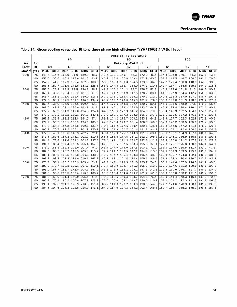
Performance Data
Table 24. Gross cooling capacities 15 tons three phase high efficiency T/YH*180G3,4,W (full load)
Ambient Temperature85 95 105
Air Ent Entering Wet BulbFlow DB 61 67 73 61 67 73 61 67 73
cfm(a) (°F) MBh SHC MBh SHC MBh SHC MBh SHC MBh SHC MBh SHC MBh SHC MBh SHC MBh SHC3000 75 149.8 116.6 163.9 91.6 180.9 48.7 142.5 112.1 155.7 88.3 172.0 46.6 134.3 106.9 146.7 84.2 162.1 43.8
80 153.0 130.6 165.9 113.6 181.8 83.7 145.7 125.4 157.8 109.4 172.9 80.6 137.5 119.5 148.7 104.5 163.1 76.8 85 157.9 141.6 167.9 129.4 182.8 108.0 150.5 135.8 159.8 124.5 173.8 104.0 142.2 129.4 150.8 118.9 164.0 99.3 90 163.8 150.7 171.9 141.5 183.7 125.5 156.2 144.5 163.7 136.0 174.7 120.8 147.7 137.7 154.6 129.9 164.9 115.5
3600 75 156.6 125.2 169.8 99.5 186.1 55.7 148.9 120.2 161.3 95.7 176.7 53.2 140.3 114.6 151.8 91.2 166.5 50.1 80 160.4 139.8 172.4 122.2 187.5 91.6 152.7 134.2 163.9 117.5 178.2 88.1 144.1 127.9 154.4 112.2 168.0 83.9 85 165.7 151.3 175.0 138.6 189.0 116.6 157.9 145.1 166.5 133.2 179.7 112.2 149.2 138.3 157.0 127.2 169.4 107.1 90 172.0 160.9 179.5 151.2 190.5 134.7 163.9 154.2 170.8 145.3 181.2 129.6 155.0 147.0 161.3 138.7 170.9 123.8
4200 75 162.6 133.0 177.9 106.6 190.4 62.0 154.5 127.6 168.8 102.4 180.7 59.1 145.5 121.6 158.9 97.5 170.0 55.5 80 166.9 148.2 178.1 129.9 192.5 98.7 158.8 142.1 169.2 124.9 182.7 94.8 149.8 135.4 159.4 119.1 172.1 90.1 85 172.7 160.2 181.3 147.0 194.5 124.4 164.5 153.6 172.3 141.2 184.8 119.5 155.4 146.3 162.5 134.8 174.1 114.1 90 179.3 170.2 186.2 160.1 196.6 143.1 170.9 163.1 177.2 153.8 186.8 137.6 161.6 155.5 167.2 146.8 176.2 131.4
4800 75 167.9 139.9 182.2 112.8 194.0 67.4 159.3 134.2 172.7 108.2 183.8 64.1 149.9 127.7 162.3 102.9 172.8 60.2 80 172.7 155.7 183.1 136.9 196.6 105.0 164.2 149.3 173.7 131.4 186.5 100.6 154.8 142.2 163.5 125.3 175.4 95.6 85 179.0 168.2 186.8 154.5 199.2 131.4 170.3 161.2 177.5 148.4 189.1 126.1 160.8 153.6 167.2 141.5 178.0 120.2 90 185.9 178.7 192.2 168.2 201.9 150.7 177.1 171.3 182.7 161.4 191.7 144.7 167.3 163.2 172.4 154.0 180.7 138.2
5400 75 172.3 146.1 185.6 118.3 202.7 72.1 163.4 139.9 175.7 113.3 191.8 68.4 153.6 133.1 164.9 107.6 180.1 64.0 80 177.8 162.5 187.3 143.1 202.9 110.5 168.8 155.6 177.5 137.2 192.2 105.7 159.0 148.1 166.9 130.6 180.6 100.3 85 184.4 175.5 191.6 161.3 203.2 137.6 175.4 168.1 181.8 154.7 192.6 131.9 165.5 160.0 171.2 147.5 181.2 125.6 90 191.7 186.4 197.4 175.5 206.4 157.5 182.5 178.6 187.5 168.3 195.8 151.1 172.3 170.1 176.8 160.5 184.4 144.1
6000 75 176.0 151.5 188.3 123.0 204.4 76.0 166.7 144.9 178.0 117.5 193.1 71.9 156.5 137.6 166.8 111.4 181.0 67.1 80 182.0 168.5 190.7 148.5 205.4 115.2 172.7 161.2 180.5 142.2 194.3 110.0 162.5 153.3 169.5 135.2 182.3 104.1 85 189.1 182.0 195.5 167.3 206.3 143.0 179.7 174.2 185.4 160.3 195.4 136.9 169.3 165.7 174.3 152.6 183.5 130.2 90 196.8 193.3 201.8 181.9 210.1 163.5 187.1 185.1 191.5 174.4 199.1 156.7 176.6 176.2 180.4 166.2 187.3 149.3
6600 75 178.9 156.1 190.2 126.9 205.4 79.1 169.2 149.1 179.5 121.0 193.7 74.5 158.6 141.4 167.9 114.5 181.2 69.3 80 185.5 173.7 193.3 153.1 207.0 119.1 175.7 166.0 182.7 146.3 195.5 113.5 165.1 157.6 171.3 139.0 183.1 107.2 85 193.0 187.7 198.7 172.5 208.7 147.6 183.2 179.5 188.2 165.1 197.3 141.1 172.4 170.6 176.7 157.0 185.1 134.0 90 201.0 199.5 205.5 187.6 213.0 168.7 190.9 190.8 194.8 179.7 201.7 161.5 180.0 180.0 183.2 171.1 189.4 153.7
7200 75 181.0 159.9 191.4 130.0 205.6 81.4 170.9 152.5 180.3 123.7 194.3 76.4 159.9 144.4 168.3 116.8 181.3 70.8 80 188.2 178.1 195.2 156.8 207.9 122.2 178.0 170.0 184.2 149.7 196.0 116.2 167.0 161.2 172.3 141.9 183.2 109.5 85 196.1 192.6 201.1 176.9 210.3 151.4 185.9 184.0 190.2 169.0 198.5 144.5 174.7 174.6 178.3 160.6 185.9 137.0 90 204.5 204.5 208.3 192.5 215.2 173.1 194.0 194.0 197.2 184.2 203.4 165.5 182.7 182.7 185.3 175.1 190.8 157.3
RT-PRC028Y-EN 51

Performance Data
Ambient Temperature115 120 125
Air Ent Entering Wet BulbFlow DB 61 67 73 61 67 73 61 67 73
cfm(a) (°F) MBh SHC MBh SHC MBh SHC MBh SHC MBh SHC MBh SHC MBh SHC MBh SHC MBh SHC3000 75 125.3 101.0 136.8 79.5 151.4 40.4 120.4 97.8 131.5 76.9 145.7 38.5 115.3 94.5 126.0 74.1 139.8 36.4
80 128.5 113.0 138.8 98.9 152.4 72.3 123.6 109.5 133.6 95.9 146.7 69.9 118.5 105.8 128.1 92.7 140.8 67.2 85 133.0 122.3 140.9 112.6 153.3 94.0 128.1 118.5 135.6 109.3 147.6 91.1 122.9 114.6 130.1 105.7 141.7 88.1 90 138.3 130.2 144.6 123.1 154.2 109.5 133.3 126.2 139.2 119.4 148.5 106.2 128.0 122.0 133.7 115.6 142.6 102.8
3600 75 130.9 108.3 141.5 86.1 155.4 46.3 125.8 105.0 138.6 83.3 149.5 44.1 120.5 101.4 132.9 80.4 143.4 41.8 80 134.6 120.9 144.1 106.2 156.8 79.0 129.5 117.2 138.7 103.0 151.0 76.3 124.3 113.3 133.0 99.6 144.9 73.5 85 139.6 130.8 146.7 120.6 158.3 101.4 134.5 126.8 141.3 117.0 152.5 98.3 129.1 122.6 135.6 113.3 146.4 95.0 90 145.2 139.0 150.9 131.5 159.8 117.4 140.0 134.8 145.3 127.7 153.9 113.9 134.5 130.5 139.6 123.6 147.9 110.3
4200 75 135.7 114.9 148.0 92.0 158.5 51.3 130.4 111.3 142.2 88.9 152.4 48.9 124.9 107.5 136.3 85.8 146.1 46.4 80 140.0 128.0 148.7 112.7 160.6 84.8 134.7 124.1 143.0 109.3 154.5 82.0 129.2 120.0 137.1 105.7 148.2 78.9 85 145.4 138.4 151.8 127.7 162.6 107.9 140.1 134.2 146.1 123.9 156.5 104.6 134.5 129.8 140.2 120.0 150.2 101.1 90 151.4 147.1 156.4 139.2 164.7 124.6 145.9 142.7 150.7 135.1 158.6 120.9 140.3 138.1 144.7 130.9 152.3 117.1
4800 75 139.7 120.6 151.0 97.0 160.9 55.5 134.2 116.8 145.1 93.8 159.7 53.0 128.5 112.9 138.9 90.4 153.1 50.2 80 144.6 134.4 152.4 118.5 163.5 89.9 139.1 130.2 146.5 114.8 159.8 86.8 133.4 125.9 140.4 111.0 153.2 83.5 85 150.4 145.3 156.1 134.0 166.1 113.7 144.9 140.8 150.2 130.0 159.8 110.2 139.1 136.3 144.1 125.9 153.3 106.5 90 156.7 154.4 161.2 146.0 168.7 130.9 151.1 149.8 155.2 141.7 162.5 127.0 145.2 145.0 149.1 137.3 156.0 123.0
5400 75 142.9 125.6 153.3 101.2 167.5 59.0 137.3 121.6 147.1 97.8 160.8 56.2 131.4 117.4 140.7 94.2 154.0 53.2 80 148.4 139.9 155.4 123.4 168.2 94.2 142.7 135.6 149.3 119.6 161.6 90.9 136.8 131.1 143.0 115.6 154.8 87.4 85 154.7 151.3 159.7 139.6 168.8 118.6 148.9 146.7 153.6 135.4 162.4 114.9 143.0 141.9 147.3 131.0 155.6 111.0 90 161.3 160.9 165.1 152.1 172.0 136.5 155.5 155.5 159.0 147.6 165.6 132.4 149.4 149.4 152.6 142.9 158.8 128.2
6000 75 145.4 129.7 154.8 104.7 168.0 61.6 139.5 125.5 148.4 101.0 161.2 58.6 133.4 121.1 141.8 97.3 154.1 55.5 80 151.4 144.7 157.6 127.6 169.4 97.6 145.5 140.1 151.3 123.5 162.6 94.1 139.4 135.4 144.8 119.3 155.6 90.5 85 158.1 156.6 162.4 144.3 170.8 122.8 152.2 151.7 156.1 139.9 164.1 118.9 146.0 146.0 149.6 135.4 157.2 114.8 90 165.1 165.1 168.4 157.3 174.6 141.2 159.1 159.1 162.0 152.6 167.9 137.0 152.8 152.8 155.4 147.8 161.0 132.5
6600 75 147.1 133.1 155.5 107.3 168.5 63.4 141.0 128.7 148.9 103.5 161.5 60.3 134.7 124.1 142.1 99.5 154.2 56.9 80 153.6 148.6 159.0 130.9 169.9 100.3 147.6 143.9 152.5 126.7 162.9 96.6 141.3 138.9 145.8 122.2 155.7 92.7 85 160.8 160.8 164.4 148.3 172.0 126.2 154.7 154.7 157.9 143.7 165.1 122.0 148.3 148.3 151.2 138.9 158.0 117.7 90 168.2 168.2 170.8 161.8 176.3 145.2 161.9 161.9 164.2 156.9 169.4 140.7 155.5 155.5 157.5 151.8 162.3 136.1
7200 75 148.0 135.6 156.1 109.2 169.1 64.5 141.7 131.0 149.4 105.1 161.8 61.1 135.2 126.2 142.4 100.9 154.4 57.5 80 155.1 151.8 159.6 133.5 170.3 102.2 148.8 146.8 152.9 129.0 163.2 98.3 142.3 141.7 146.0 124.4 155.8 94.2 85 162.7 162.7 165.6 151.4 172.4 128.8 156.4 156.4 158.9 146.6 165.3 124.4 149.8 149.8 152.0 141.6 158.7 119.9 90 170.4 170.4 172.4 165.4 177.3 148.4 164.0 164.0 165.7 160.4 170.2 143.7 157.3 157.3 158.7 155.1 162.8 138.8
Notes: 1. All capacities shown are gross and have not considered indoor fan heat. To obtain NET cooling capacity subtract indoor fan heat. For indoor fan heat
formula, refer to appropriate airflow table notes. 2. MBh = Total Gross Capacity 3. SHC = Sensible Heat Capacity 4. *Indicates both downflow and horizontal units.
(a)For 3000, 3600, and 4200 cfm-Unit applications below 320 cfm/ton are only applicable to Constant Volume THD models without electric heat and YHD models equipped with modulating gas heat. See below for restrictions:- Electric heaters on applications below 320 cfm/ton.- Dehumidification (Hot Gas Reheat) with Frostat and Crankcage heaters are required on applications below 320 cfm/ton.- Multi-speed or single zone VAV applications are capable of running below 320 cfm/ton during low speed airflow operation, but "full" airflow must be set to 320 cfm/ton or higher.
Table 24. Gross cooling capacities 15 tons three phase high efficiency T/YH*180G3,4,W (full load)
52 RT-PRC028Y-EN

Performance Data
Table 25. Gross cooling capacities 15 tons three phase dehumidification (hot gas reheat) option high efficiency T/YHD180G3,4,W (Digit 22 = B)
Ambient Temperature85 95 105
Air Ent Entering Wet BulbFlow DB 61 67 73 61 67 73 61 67 73
cfm(a) (°F) MBh SHC MBh SHC MBh SHC MBh SHC MBh SHC MBh SHC MBh SHC MBh SHC MBh SHC3000 75 149.8 108.9 167.7 71.3 190.8 66.8 141.5 104.7 158.6 68.7 180.8 63.3 132.6 99.7 148.8 65.2 170.1 59.5
80 151.5 129.2 166.7 101.1 187.0 65.5 143.4 124.3 157.7 97.7 177.1 62.0 134.7 118.5 148.1 93.4 166.7 58.3 85 154.6 144.8 167.0 126.0 184.5 89.1 146.7 139.2 158.2 121.9 174.9 86.5 138.1 132.6 148.8 116.9 164.6 83.0 90 159.1 155.7 168.7 146.3 183.5 118.7 151.3 149.2 160.1 141.4 174.0 115.3 143.0 141.9 150.9 135.6 163.9 111.1
3900 75 160.4 120.9 176.9 82.0 198.6 69.5 151.6 116.3 167.3 79.0 188.1 65.8 142.3 110.9 157.1 75.1 177.0 61.9 80 163.1 142.6 176.9 113.1 195.8 68.5 154.6 137.2 167.5 109.3 185.5 64.9 145.4 131.0 157.4 104.6 174.5 61.1 85 167.2 159.5 178.2 139.4 194.4 101.1 158.8 153.4 169.0 134.8 184.2 98.1 149.8 146.4 159.1 129.4 173.5 94.2 90 172.7 171.6 180.9 160.9 194.3 132.0 164.5 164.5 171.9 155.6 184.3 128.2 155.7 155.7 162.2 149.4 173.8 123.5
4800 75 169.3 131.7 184.4 91.5 204.6 71.6 160.0 126.7 174.3 88.0 193.7 67.8 150.2 120.8 163.6 83.7 182.1 63.7 80 173.0 154.7 185.4 123.8 202.8 74.8 164.0 148.9 175.5 119.6 192.1 72.1 154.3 142.3 164.9 114.5 180.7 68.6 85 178.1 172.9 187.7 151.4 202.4 111.8 169.3 166.4 178.0 146.5 191.8 108.4 159.8 159.0 167.7 140.6 180.6 104.0 90 184.6 184.6 191.4 174.3 203.4 144.0 176.0 176.0 181.9 168.5 192.9 139.8 166.7 166.7 171.7 161.9 181.9 134.7
5400 75 174.2 138.2 188.4 97.1 207.7 72.7 164.7 132.9 178.0 93.4 196.4 68.7 154.6 126.8 167.0 88.8 184.5 64.6 80 178.6 162.0 190.0 130.3 206.6 80.4 169.3 156.0 179.8 125.8 195.5 77.4 159.3 149.1 169.0 120.4 183.8 73.6 85 184.4 181.1 193.1 158.8 206.8 118.2 175.3 174.3 183.0 153.5 195.9 114.5 165.5 165.5 172.4 147.4 184.4 109.9 90 191.6 191.6 197.4 182.5 208.4 151.4 182.6 182.6 187.6 176.5 197.7 146.9 173.0 173.0 177.2 169.5 186.4 141.5
6000 75 178.4 144.1 191.6 102.1 210.0 73.5 168.5 138.6 180.9 98.1 198.4 69.4 158.1 132.1 169.6 93.2 186.2 65.2 80 183.5 168.8 193.9 136.2 209.5 85.4 173.8 162.5 183.4 131.4 198.1 82.2 163.6 155.3 172.3 125.8 186.1 78.1 85 189.9 188.8 197.6 165.5 210.4 124.1 180.5 180.5 187.3 160.0 199.2 120.1 170.4 170.4 176.4 153.6 187.4 115.3 90 197.8 197.8 202.7 190.1 212.7 158.1 188.5 188.5 192.6 183.8 201.7 153.4 178.6 178.6 181.8 176.6 190.1 147.7
6600 75 181.8 149.5 194.1 106.6 211.5 74.0 171.6 143.7 183.0 102.3 199.6 69.9 160.9 137.0 171.4 97.1 187.1 65.5 80 187.5 175.0 197.1 141.5 211.7 89.9 177.6 168.5 186.2 136.5 200.0 86.4 167.0 161.0 174.8 130.6 187.7 82.0 85 194.7 194.7 201.4 171.8 213.3 129.5 184.9 184.9 190.8 166.0 201.8 125.2 174.5 174.5 179.5 159.2 189.7 120.0 90 203.2 203.2 207.2 197.2 216.3 164.3 193.6 193.6 196.7 190.6 204.9 159.3 183.4 183.4 185.6 183.2 193.0 153.3
7200 75 184.4 154.3 195.7 110.5 212.2 74.3 173.9 148.2 184.4 105.9 200.0 70.0 162.9 141.2 172.5 100.5 187.2 65.5 80 190.8 180.7 199.4 146.3 213.1 93.8 180.6 173.9 188.3 141.0 201.1 90.0 169.7 166.1 176.5 134.8 188.5 85.3 85 198.7 198.7 204.5 177.4 215.4 134.2 188.6 188.6 193.5 171.3 203.6 129.7 177.9 177.9 181.9 164.3 191.1 124.2 90 207.8 207.8 210.9 203.8 219.0 170.0 198.0 198.0 200.1 196.9 207.4 164.6 188.7 188.7 188.7 188.7 195.1 158.4
RT-PRC028Y-EN 53

Performance Data
Ambient Temperature115 120 125
Air Ent Entering Wet BulbFlow DB 61 67 73 61 67 73 61 67 73
cfm(a) (°F) MBh SHC MBh SHC MBh SHC MBh SHC MBh SHC MBh SHC MBh SHC MBh SHC MBh SHC3000 75 123.1 93.8 138.4 60.9 158.9 55.6 118.1 90.5 133.0 58.3 153.0 53.5 112.9 87.0 127.4 55.6 147.0 51.4
80 125.3 111.8 137.9 88.3 155.6 54.5 120.4 108.1 132.6 85.4 149.8 52.4 115.4 104.2 127.1 82.2 143.9 50.4 85 129.0 125.1 138.8 111.0 153.7 78.6 124.2 121.1 133.5 107.7 148.0 76.1 119.2 116.8 128.1 104.1 142.2 73.3 90 134.0 133.7 141.0 128.9 153.1 105.9 129.3 129.2 135.9 125.2 147.6 103.0 124.4 124.4 130.6 121.3 141.8 99.9
3900 75 132.3 104.6 146.2 70.3 165.3 57.8 127.1 101.1 140.6 67.6 159.2 55.7 121.7 97.3 134.7 64.6 152.9 53.5 80 135.6 123.9 146.7 99.0 163.0 57.1 130.5 120.0 141.2 95.9 157.0 54.9 125.2 115.9 135.4 92.6 150.8 52.8 85 140.2 138.5 148.6 123.0 162.1 89.3 135.2 134.2 143.1 119.5 156.2 86.6 130.0 129.7 137.5 115.8 150.1 83.6 90 146.3 146.3 151.9 142.3 162.6 118.0 141.3 141.3 146.5 138.4 156.8 114.8 136.2 136.2 140.9 134.2 150.8 111.5
4800 75 139.8 114.1 152.3 78.5 169.9 59.5 134.3 110.4 146.4 75.5 163.6 57.3 128.7 106.4 140.4 72.4 157.1 55.0 80 144.1 134.7 153.8 108.5 168.7 64.1 138.7 130.6 148.0 105.2 162.4 61.6 133.2 126.3 142.1 101.6 156.0 58.8 85 149.8 149.8 156.7 133.8 168.8 98.8 144.5 144.5 151.0 130.1 162.6 95.9 139.1 139.1 145.1 126.2 156.4 92.7 90 156.8 156.8 161.0 154.4 170.3 128.7 151.6 151.6 155.4 150.3 164.2 125.4 146.3 146.3 149.6 145.9 158.0 121.8
5400 75 143.8 119.7 155.4 83.3 172.0 60.2 138.2 115.9 149.3 80.2 165.6 57.9 132.4 111.8 143.1 76.9 158.9 55.6 80 148.8 141.3 157.6 114.2 171.5 68.9 143.3 137.0 151.6 110.7 165.1 66.2 137.6 132.6 145.5 107.0 158.5 63.3 85 155.1 155.1 161.1 140.3 172.3 104.4 149.7 149.7 155.3 136.5 166.0 101.3 144.1 144.1 149.3 132.4 159.5 98.0 90 162.8 162.8 166.1 161.7 174.4 135.2 157.5 157.5 160.3 157.5 168.2 131.7 152.9 152.0 154.4 153.0 161.9 128.0
6000 75 147.1 124.8 157.7 87.5 173.4 60.7 141.3 120.8 151.5 84.2 166.8 58.4 135.4 116.6 145.1 80.8 160.0 56.0 80 152.7 147.2 160.5 119.2 173.5 73.1 147.0 142.8 154.4 115.6 167.0 70.2 141.2 138.2 148.2 111.8 160.3 67.2 85 159.7 159.7 164.8 146.3 175.0 109.5 154.2 154.2 158.8 142.3 168.5 106.2 148.4 148.4 152.6 138.0 161.9 102.8 90 168.7 168.1 170.4 168.5 177.8 141.1 162.8 162.8 164.5 164.2 171.5 137.5 158.4 158.4 158.4 158.4 165.0 133.7
6600 75 149.5 129.4 159.2 91.1 174.0 60.9 143.6 125.2 152.8 87.7 167.2 58.5 137.6 120.9 146.3 84.1 160.3 56.1 80 155.9 152.6 162.7 123.7 174.8 76.7 150.0 148.1 156.5 120.0 168.1 73.7 144.1 143.4 150.1 116.0 161.2 70.5 85 163.6 163.6 167.7 151.6 176.9 114.0 157.8 157.8 161.5 147.5 170.3 110.6 151.9 151.9 155.2 143.1 163.6 107.0 90 174.0 174.0 174.0 174.0 180.4 146.5 167.9 167.9 167.9 167.9 173.9 142.7 161.7 161.7 161.7 161.7 167.3 138.8
7200 75 151.2 133.3 159.9 94.2 173.8 60.8 145.2 129.0 153.4 90.7 166.9 58.4 138.9 124.6 146.8 86.9 159.8 55.9 80 158.2 157.5 164.2 127.7 175.2 79.7 152.3 152.3 157.8 123.8 168.4 76.6 146.1 146.1 151.2 119.7 161.4 73.3 85 166.6 166.6 169.8 156.5 178.1 117.9 160.7 160.7 163.5 152.2 171.3 114.4 154.7 154.7 157.0 147.7 164.4 110.7 90 176.7 176.7 176.7 176.7 182.3 151.3 170.5 170.5 170.5 170.5 175.6 147.4 164.1 164.1 164.1 164.1 168.8 143.3
Notes: 1. All capacities shown are gross and have not considered indoor fan heat. To obtain NET cooling capacity subtract indoor fan heat. For indoor fan heat
formula, refer to appropriate airflow table notes. 2. MBh = Total Gross Capacity 3. SHC = Sensible Heat Capacity
(a)For 3000 and 3900 cfm-Unit applications below 320 cfm/ton are only applicable to Constant Volume THD models without electric heat and YHD models equipped with modulating gas heat. See below for restrictions:- Electric heaters on applications below 320 cfm/ton.- Dehumidification (Hot Gas Reheat) with Frostat and Crankcage heaters are required on applications below 320 cfm/ton.- Multi-speed or single zone VAV applications are capable of running below 320 cfm/ton during low speed airflow operation, but "full" airflow must be set to 320 cfm/ton or higher.
Table 25. Gross cooling capacities 15 tons three phase dehumidification (hot gas reheat) option high efficiency T/YHD180G3,4,W (Digit 22 = B)
54 RT-PRC028Y-EN
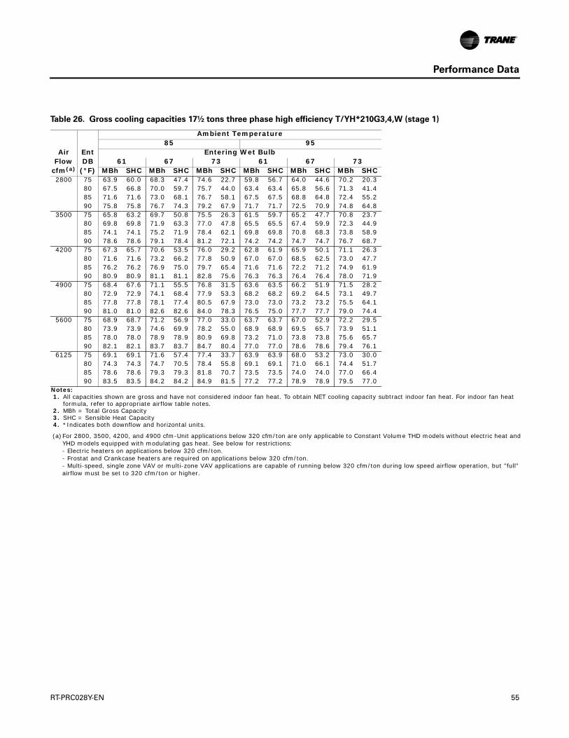
Performance Data
Table 26. Gross cooling capacities 17½ tons three phase high efficiency T/YH*210G3,4,W (stage 1)
Ambient Temperature85 95
Air Ent Entering Wet BulbFlow DB 61 67 73 61 67 73
cfm(a) (°F) MBh SHC MBh SHC MBh SHC MBh SHC MBh SHC MBh SHC2800 75 63.9 60.0 68.3 47.4 74.6 22.7 59.8 56.7 64.0 44.6 70.2 20.3
80 67.5 66.8 70.0 59.7 75.7 44.0 63.4 63.4 65.8 56.6 71.3 41.4 85 71.6 71.6 73.0 68.1 76.7 58.1 67.5 67.5 68.8 64.8 72.4 55.2 90 75.8 75.8 76.7 74.3 79.2 67.9 71.7 71.7 72.5 70.9 74.8 64.8
3500 75 65.8 63.2 69.7 50.8 75.5 26.3 61.5 59.7 65.2 47.7 70.8 23.7 80 69.8 69.8 71.9 63.3 77.0 47.8 65.5 65.5 67.4 59.9 72.3 44.9 85 74.1 74.1 75.2 71.9 78.4 62.1 69.8 69.8 70.8 68.3 73.8 58.9 90 78.6 78.6 79.1 78.4 81.2 72.1 74.2 74.2 74.7 74.7 76.7 68.7
4200 75 67.3 65.7 70.6 53.5 76.0 29.2 62.8 61.9 65.9 50.1 71.1 26.3 80 71.6 71.6 73.2 66.2 77.8 50.9 67.0 67.0 68.5 62.5 73.0 47.7 85 76.2 76.2 76.9 75.0 79.7 65.4 71.6 71.6 72.2 71.2 74.9 61.9 90 80.9 80.9 81.1 81.1 82.8 75.6 76.3 76.3 76.4 76.4 78.0 71.9
4900 75 68.4 67.6 71.1 55.5 76.8 31.5 63.6 63.5 66.2 51.9 71.5 28.2 80 72.9 72.9 74.1 68.4 77.9 53.3 68.2 68.2 69.2 64.5 73.1 49.7 85 77.8 77.8 78.1 77.4 80.5 67.9 73.0 73.0 73.2 73.2 75.5 64.1 90 81.0 81.0 82.6 82.6 84.0 78.3 76.5 75.0 77.7 77.7 79.0 74.4
5600 75 68.9 68.7 71.2 56.9 77.0 33.0 63.7 63.7 67.0 52.9 72.2 29.5 80 73.9 73.9 74.6 69.9 78.2 55.0 68.9 68.9 69.5 65.7 73.9 51.1 85 78.0 78.0 78.9 78.9 80.9 69.8 73.2 71.0 73.8 73.8 75.6 65.7 90 82.1 82.1 83.7 83.7 84.7 80.4 77.0 77.0 78.6 78.6 79.4 76.1
6125 75 69.1 69.1 71.6 57.4 77.4 33.7 63.9 63.9 68.0 53.2 73.0 30.0 80 74.3 74.3 74.7 70.5 78.4 55.8 69.1 69.1 71.0 66.1 74.4 51.7 85 78.6 78.6 79.3 79.3 81.8 70.7 73.5 73.5 74.0 74.0 77.0 66.4 90 83.5 83.5 84.2 84.2 84.9 81.5 77.2 77.2 78.9 78.9 79.5 77.0
Notes: 1. All capacities shown are gross and have not considered indoor fan heat. To obtain NET cooling capacity subtract indoor fan heat. For indoor fan heat
formula, refer to appropriate airflow table notes. 2. MBh = Total Gross Capacity 3. SHC = Sensible Heat Capacity 4. *Indicates both downflow and horizontal units.
(a)For 2800, 3500, 4200, and 4900 cfm-Unit applications below 320 cfm/ton are only applicable to Constant Volume THD models without electric heat and YHD models equipped with modulating gas heat. See below for restrictions:- Electric heaters on applications below 320 cfm/ton.- Frostat and Crankcase heaters are required on applications below 320 cfm/ton.- Multi-speed, single zone VAV or multi-zone VAV applications are capable of running below 320 cfm/ton during low speed airflow operation, but "full" airflow must be set to 320 cfm/ton or higher.
RT-PRC028Y-EN 55

Performance Data
Table 27. Gross cooling capacities 17½ tons three phase high efficiency T/YH*210G3,4,W (stage 2)
Ambient Temperature85 95
Air Ent Entering Wet BulbFlow DB 61 67 73 61 67 73
cfm(a) (°F) MBh SHC MBh SHC MBh SHC MBh SHC MBh SHC MBh SHC2800 75 123.5 100.2 134.4 80.1 147.8 44.0 117.3 96.3 127.4 77.0 139.9 41.8
80 126.3 111.0 136.4 97.8 148.9 73.2 120.1 106.7 129.4 94.1 141.1 70.2 85 130.4 119.4 138.3 110.3 150.0 92.9 124.2 114.7 131.3 106.1 142.3 89.4 90 135.4 126.3 141.8 119.6 151.1 106.9 129.0 121.3 134.8 115.0 143.4 102.8
3500 75 129.9 108.5 142.2 87.5 152.2 50.4 123.2 104.2 134.6 84.0 143.9 47.6 80 133.3 120.2 142.4 106.1 154.0 80.6 126.7 115.4 135.0 102.0 145.8 77.2 85 138.0 129.2 145.1 119.4 155.8 101.2 131.3 124.0 137.7 114.7 147.7 97.2 90 143.5 136.7 149.2 129.3 157.7 115.9 136.7 131.2 141.7 124.3 149.6 111.4
4200 75 135.1 115.8 146.3 93.8 160.5 55.6 128.0 111.0 138.3 89.8 151.6 52.4 80 139.3 128.2 147.4 113.3 160.5 86.9 132.2 122.9 139.6 108.7 151.8 83.0 85 144.5 137.8 150.7 127.3 160.6 108.4 137.4 132.2 142.9 122.2 152.0 103.9 90 150.5 145.9 155.4 137.9 163.1 123.8 143.2 139.9 147.6 132.5 154.6 118.9
4900 75 139.2 121.9 149.3 99.0 162.4 59.6 131.7 116.7 140.9 94.5 153.0 56.0 80 144.1 135.1 151.3 119.4 163.3 92.0 136.6 129.4 143.0 114.3 154.1 87.7 85 149.9 145.4 155.3 134.1 164.2 114.4 142.4 139.3 147.1 128.6 155.2 109.5 90 156.3 153.9 160.6 145.4 167.5 130.6 148.6 147.5 152.3 139.5 158.5 125.3
5600 75 142.3 126.9 151.2 103.0 163.2 62.6 134.3 121.2 142.3 98.1 153.4 58.5 80 147.8 140.8 154.1 124.3 165.0 96.0 139.9 134.7 145.3 118.8 155.4 91.2 85 154.2 151.7 158.8 139.8 166.8 119.3 146.3 145.2 150.1 133.8 157.4 114.0 90 161.1 160.8 164.6 151.7 170.7 136.3 152.9 152.9 155.9 145.4 161.4 130.5
6125 75 143.8 129.9 151.9 105.3 164.1 64.0 135.5 123.9 142.7 100.0 154.0 59.6 80 149.9 144.4 155.4 127.3 165.5 98.3 141.7 137.9 146.4 121.4 155.6 93.2 85 156.7 155.8 160.7 143.3 168.0 122.3 148.4 148.4 151.7 137.0 158.2 116.6 90 163.9 163.9 167.0 155.7 172.5 139.8 155.4 155.4 157.9 149.0 162.8 133.6
Notes: 1. All capacities shown are gross and have not considered indoor fan heat. To obtain NET cooling capacity subtract indoor fan heat. For indoor fan heat
formula, refer to appropriate airflow table notes. 2. MBh = Total Gross Capacity 3. SHC = Sensible Heat Capacity 4. *Indicates both downflow and horizontal units.
(a)For 2800, 3500, 4200, and 4900 cfm-Unit applications below 320 cfm/ton are only applicable to Constant Volume THD models without electric heat and YHD models equipped with modulating gas heat. See below for restrictions:- Electric heaters on applications below 320 cfm/ton.- Frostat and Crankcase heaters are required on applications below 320 cfm/ton.- Multi-speed, single zone VAV or multi-zone VAV applications are capable of running below 320 cfm/ton during low speed airflow operation, but "full" airflow must be set to 320 cfm/ton or higher.
56 RT-PRC028Y-EN

Performance Data
Table 28. Gross cooling capacities 17½ tons three phase high efficiency T/YH*210G3,4,W (full load)
Ambient Temperature85 95 105
Air Ent Entering Wet BulbFlow DB 61 67 73 61 67 73 61 67 73
cfm(a) (°F) MBh SHC MBh SHC MBh SHC MBh SHC MBh SHC MBh SHC MBh SHC MBh SHC MBh SHC3500 75 178.2 140.1 193.8 111.1 207.3 60.7 169.5 134.8 186.6 107.2 204.8 58.4 159.9 128.9 174.5 102.7 183.6 55.5
80 182.3 156.6 197.4 136.9 211.8 102.1 173.6 150.4 187.6 132.0 205.4 98.5 164.0 143.7 177.0 126.4 187.8 94.3 85 188.5 169.5 200.2 155.6 217.6 130.7 179.6 162.7 190.4 149.7 206.7 126.0 169.9 155.2 179.7 143.3 195.0 120.8 90 195.9 180.3 205.3 169.8 219.0 151.3 186.7 172.9 195.3 163.3 208.1 145.8 176.7 164.9 184.5 156.2 196.4 139.7
4200 75 186.2 150.2 194.6 120.2 212.8 68.8 177.0 144.4 193.2 115.8 211.6 66.0 166.9 138.0 183.6 110.8 196.3 62.6 80 191.0 167.4 205.2 147.0 223.4 111.3 181.8 160.8 194.9 141.5 212.2 107.2 171.7 153.5 183.7 135.5 198.7 102.5 85 197.7 181.0 208.6 166.4 225.1 140.8 188.3 173.7 198.3 160.1 213.7 135.6 178.1 165.7 187.1 153.2 201.5 129.9 90 205.5 192.4 214.2 181.3 227.2 162.2 195.9 184.5 203.8 174.3 215.8 156.2 185.3 176.0 192.4 166.7 203.5 149.6
4900 75 193.4 159.4 211.5 128.5 229.7 76.0 183.6 153.0 200.5 123.6 217.5 72.7 173.0 146.1 188.6 118.0 204.6 68.8 80 198.8 177.4 212.0 156.2 230.6 119.6 189.1 170.2 201.2 150.2 218.2 114.9 178.5 162.4 189.5 143.6 205.4 109.7 85 206.0 191.6 216.1 176.3 231.7 150.0 196.1 183.7 205.2 169.5 219.8 144.3 185.4 175.3 193.6 162.1 207.0 138.0 90 214.3 203.5 222.3 191.9 234.4 172.2 204.1 195.1 211.3 184.4 222.5 165.6 193.0 186.1 199.4 176.3 209.8 158.5
5600 75 199.6 167.6 216.7 135.8 236.2 82.3 189.4 160.8 205.1 130.4 223.6 78.5 178.3 153.3 192.7 124.3 206.4 74.0 80 205.7 186.4 218.0 164.4 237.1 126.9 195.5 178.7 206.6 157.9 224.2 121.8 184.4 170.4 194.4 150.8 211.7 116.0 85 213.5 201.3 222.7 185.3 237.4 158.2 203.1 192.9 211.4 178.0 225.0 152.0 191.8 183.9 199.1 170.0 211.7 145.2 90 222.1 213.8 229.4 201.6 240.8 181.2 211.4 204.9 217.9 193.6 228.4 174.2 199.8 195.3 205.5 184.9 215.1 166.5
6300 75 205.0 174.9 220.9 142.2 240.8 87.7 194.2 167.6 208.8 136.2 227.7 83.3 182.6 159.6 195.9 129.7 208.9 78.4 80 211.7 194.5 223.1 171.7 241.7 133.3 201.0 186.3 211.2 164.7 228.6 127.7 189.4 177.4 198.5 157.1 214.6 121.4 85 220.0 210.0 228.4 193.4 242.2 165.6 209.1 201.1 216.6 185.6 229.3 158.8 197.3 191.6 203.8 177.1 215.5 151.5 90 229.1 223.1 235.7 210.4 246.2 189.3 217.8 213.7 223.6 201.8 233.3 181.8 205.7 203.6 210.8 192.6 219.5 173.6
7000 75 209.4 181.3 224.2 147.7 243.2 92.1 198.2 173.4 211.7 141.2 230.3 87.2 186.0 165.0 198.2 134.1 210.2 81.8 80 216.9 201.6 227.2 178.1 244.8 138.8 205.6 192.9 214.8 170.5 231.2 132.7 193.4 183.6 201.6 162.4 216.7 125.9 85 225.6 217.8 233.3 200.6 246.1 172.0 214.2 208.4 220.9 192.2 232.7 164.7 201.9 198.4 207.6 183.2 218.4 156.9 90 235.1 231.5 241.0 218.2 250.8 196.5 223.4 221.5 228.5 209.1 237.4 188.4 210.8 210.8 215.1 199.4 223.1 179.7
7700 75 213.0 186.8 226.7 152.2 245.6 95.6 201.2 178.4 213.6 145.2 231.9 90.2 188.6 169.4 199.6 137.6 210.6 84.2 80 221.1 207.9 230.5 183.5 247.0 143.4 209.3 198.6 217.6 175.5 232.8 136.7 196.6 188.8 203.8 166.8 217.9 129.4 85 230.4 224.7 237.2 206.8 249.1 177.5 218.4 214.8 224.3 197.9 235.2 169.7 205.6 204.3 210.5 188.4 220.4 161.4 90 240.3 238.9 245.5 225.1 254.5 202.8 228.0 228.0 232.4 215.5 240.5 194.2 214.9 214.9 218.5 205.3 225.7 185.0
8400 75 215.7 191.3 228.2 155.8 246.8 98.2 203.4 182.4 214.6 148.3 232.7 92.3 190.2 172.9 200.2 140.2 220.4 85.8 80 224.4 213.2 232.9 188.1 248.3 147.1 212.1 203.4 219.5 179.5 233.6 139.9 199.0 193.1 205.2 170.3 220.8 132.1 85 234.2 230.7 240.2 212.1 251.3 182.0 221.8 220.3 226.8 202.7 236.8 173.8 208.4 208.4 212.6 192.7 221.5 164.9 90 244.5 244.5 249.1 231.1 257.3 208.1 231.8 231.8 235.5 221.0 242.8 199.0 218.1 218.1 221.1 210.2 227.5 189.3
RT-PRC028Y-EN 57

Performance Data
Ambient Temperature115 120 125
Air Ent Entering Wet BulbFlow DB 61 67 73 61 67 73 61 67 73
cfm(a) (°F) MBh SHC MBh SHC MBh SHC MBh SHC MBh SHC MBh SHC MBh SHC MBh SHC MBh SHC3500 75 149.5 122.4 158.0 97.6 172.5 52.1 144.0 119.0 155.8 94.8 165.9 50.1 138.2 115.3 148.3 91.9 160.8 48.0
80 153.6 136.3 165.4 120.3 176.7 89.5 148.1 132.4 159.3 117.0 169.4 86.9 142.3 128.4 153.0 113.5 163.4 84.1 85 159.3 147.2 168.2 136.3 182.4 114.9 153.7 143.0 162.1 132.6 175.8 111.8 147.8 138.6 155.8 128.7 169.0 108.4 90 165.8 156.4 172.8 148.5 183.8 133.0 160.1 151.8 166.7 144.4 177.2 129.4 154.1 147.2 160.3 140.2 170.4 125.7
4200 75 156.0 131.0 171.4 105.2 184.6 58.6 150.2 127.2 164.9 102.2 174.8 56.4 144.2 123.3 158.3 99.0 162.4 54.0 80 160.8 145.6 171.6 128.8 186.8 97.2 155.0 141.5 165.3 125.2 175.3 94.3 149.0 137.2 158.7 121.5 168.6 91.2 85 167.0 157.2 175.0 145.6 188.4 123.5 161.1 152.7 168.7 141.6 181.5 120.1 155.0 148.0 162.1 137.5 174.4 116.5 90 173.9 166.9 180.2 158.5 190.4 142.3 167.9 162.1 173.8 154.1 183.6 138.5 161.6 157.2 167.1 149.6 176.5 134.5
4900 75 161.6 138.6 175.9 111.9 190.2 64.3 155.5 134.6 169.2 108.6 180.7 61.8 149.3 130.4 162.3 105.2 175.1 59.2 80 167.0 154.0 176.9 136.4 192.8 103.9 161.0 149.6 170.3 132.6 181.3 100.7 154.7 145.0 163.5 128.6 176.4 97.4 85 173.7 166.2 181.0 154.0 193.4 131.1 167.6 161.4 174.4 149.8 186.3 127.4 161.3 156.5 167.6 145.3 178.9 123.6 90 181.1 176.5 186.7 167.5 196.1 150.7 174.8 171.5 180.0 162.9 189.0 146.6 168.3 166.3 173.1 158.2 181.7 142.4
5600 75 166.3 145.3 179.4 117.7 192.5 69.0 160.0 141.0 172.5 114.1 184.5 66.3 153.5 136.6 165.3 110.4 176.9 63.4 80 172.4 161.5 181.4 143.1 197.4 109.7 166.1 156.8 174.5 139.0 189.9 106.3 159.6 152.0 167.4 134.8 182.2 102.7 85 179.6 174.3 186.1 161.5 197.6 137.8 173.2 169.3 179.2 157.0 190.2 133.9 166.6 164.1 172.1 152.3 182.6 129.8 90 187.4 185.2 192.3 175.7 201.0 158.2 180.9 179.9 185.4 170.8 193.6 153.9 174.1 174.1 178.2 165.8 186.0 149.3
6300 75 170.1 151.0 182.1 122.5 194.1 72.8 163.6 146.5 174.9 118.7 185.6 69.8 156.8 141.9 167.5 114.8 178.3 66.7 80 176.9 168.0 184.9 148.8 199.8 114.6 170.3 163.1 177.8 144.5 192.1 110.9 163.5 158.0 170.4 140.0 184.1 107.1 85 184.6 181.5 190.2 168.0 200.8 143.6 178.0 176.2 183.1 163.2 193.2 139.4 171.1 170.8 175.8 158.3 185.3 135.1 90 192.8 192.8 197.0 182.9 204.9 164.8 186.0 186.0 189.8 177.7 197.2 160.2 179.0 179.0 182.4 172.5 189.4 155.4
7000 75 173.0 155.9 183.9 126.5 194.4 75.7 166.2 151.1 176.5 122.4 186.5 72.4 159.2 146.2 168.8 118.2 178.8 69.0 80 180.4 173.6 187.5 153.7 201.3 118.5 173.6 168.4 180.1 149.1 193.3 114.6 166.6 163.1 172.5 144.3 185.1 110.5 85 188.7 187.8 193.5 173.6 203.2 148.5 181.8 181.8 186.2 168.6 195.3 144.0 174.7 174.7 178.6 163.4 187.2 139.4 90 197.3 197.3 200.8 189.1 207.9 170.4 190.2 190.2 193.4 183.8 200.0 165.5 183.0 183.0 185.7 178.2 191.9 160.5
7700 75 175.1 159.8 184.8 129.4 195.2 77.6 168.0 154.8 177.1 125.1 187.2 74.1 160.7 149.6 169.2 120.7 179.2 70.5 80 183.1 178.3 189.2 157.6 202.0 121.5 176.0 172.9 181.6 152.7 193.7 117.4 168.7 167.3 173.8 147.7 185.3 113.0 85 191.9 191.9 195.9 178.3 204.7 152.4 184.8 184.8 188.3 173.0 196.5 147.7 177.4 177.4 180.4 167.6 188.1 142.8 90 200.9 200.9 203.8 194.5 210.1 175.1 193.6 193.6 196.0 188.8 201.9 170.0 186.1 186.1 188.1 183.1 193.5 164.7
8400 75 176.2 162.8 184.8 131.5 195.6 78.7 168.9 157.5 177.8 126.9 187.9 74.9 161.3 152.0 170.0 122.2 180.3 71.0 80 184.9 182.1 190.1 160.6 202.4 123.6 177.6 176.4 182.2 155.4 194.3 119.2 170.0 170.0 174.1 150.2 184.4 114.6 85 194.2 194.2 197.4 182.1 205.3 155.4 186.8 186.8 189.5 176.5 196.8 150.4 179.2 179.2 181.4 170.8 188.2 145.3 90 203.6 203.6 205.8 198.9 211.3 178.9 196.1 196.1 197.8 193.0 202.9 173.5 188.3 188.3 189.6 187.0 194.2 168.0
Notes: 1. All capacities shown are gross and have not considered indoor fan heat. To obtain NET cooling capacity subtract indoor fan heat. For indoor fan heat
formula, refer to appropriate airflow table notes. 2. MBh = Total Gross Capacity 3. SHC = Sensible Heat Capacity 4. *Indicates both downflow and horizontal units.
(a)For 3500, 4200, and 4900 cfm-Unit applications below 320 cfm/ton are only applicable to Constant Volume THD models without electric heat and YHD models equipped with modulating gas heat. See below for restrictions:- Electric heaters on applications below 320 cfm/ton.- Frostat and Crankcase heaters are required on applications below 320 cfm/ton.- Multi-speed, single zone VAV or multi-zone VAV applications are capable of running below 320 cfm/ton during low speed airflow operation, but "full" airflow must be set to 320 cfm/ton or higher.
Table 28. Gross cooling capacities 17½ tons three phase high efficiency T/YH*210G3,4,W (full load)
58 RT-PRC028Y-EN

Performance Data
Table 29. Gross cooling capacities 17½ tons three phase dehumidification (hot gas reheat) option high efficiency T/YHD210G3,4,W (Digit 22 = B)
Ambient Temperature85 95 105
Air Ent Entering Wet BulbFlow DB 61 67 73 61 67 73 61 67 73
cfm(a) (°F) MBh SHC MBh SHC MBh SHC MBh SHC MBh SHC MBh SHC MBh SHC MBh SHC MBh SHC3500 75 157.6 122.6 174.5 95.9 196.1 56.8 151.2 119.5 166.8 93.6 187.2 55.2 143.7 115.7 158.2 90.5 177.3 53.0
80 160.6 140.5 174.2 120.6 192.5 88.1 154.0 136.7 166.5 117.6 183.6 85.9 146.5 132.2 157.8 113.8 173.6 83.085 165.2 154.7 175.6 141.4 190.7 115.7 158.6 150.2 167.8 137.7 181.7 112.8 151.0 145.0 159.0 133.3 171.6 109.290 171.5 165.0 178.7 158.5 190.5 139.5 164.8 159.9 170.8 154.1 181.4 135.9 157.2 154.0 161.9 149.1 171.3 131.6
4550 75 167.1 138.7 182.4 110.5 202.3 69.8 160.1 134.8 174.2 107.4 192.8 67.5 152.2 130.2 164.9 103.5 182.4 64.480 171.1 158.1 183.1 136.6 199.7 102.6 164.0 153.5 174.8 132.7 190.2 99.5 156.0 148.2 165.5 128.2 179.7 95.885 176.7 173.6 185.5 158.8 198.9 131.5 169.6 168.3 177.1 154.3 189.3 127.8 161.4 161.4 167.7 149.1 178.7 123.490 184.0 184.0 189.5 177.3 199.7 156.7 176.8 176.8 181.1 172.1 190.0 152.3 168.6 168.6 171.6 166.2 179.4 147.2
5600 75 174.9 145.5 188.5 116.5 206.7 75.0 167.3 141.2 179.7 113.0 196.7 72.3 158.8 136.2 169.9 108.7 185.7 68.880 179.8 165.5 190.1 143.2 205.1 108.5 172.2 160.6 181.3 139.0 195.1 105.0 163.6 154.9 171.5 134.1 184.0 100.985 186.4 181.8 193.5 166.2 205.3 138.1 178.7 176.1 184.6 161.3 195.1 134.0 170.0 169.7 174.7 155.7 184.0 129.290 194.7 194.2 198.5 185.3 207.0 164.0 186.9 186.9 189.5 179.8 196.8 159.2 178.1 178.1 179.6 173.5 185.7 153.7
6300 75 179.1 151.4 191.5 121.6 208.6 79.4 171.1 146.7 182.4 117.7 198.3 76.2 162.2 141.3 172.3 113.1 187.0 72.480 184.6 172.1 193.9 149.1 207.7 113.5 176.6 166.8 184.7 144.5 197.3 109.7 167.7 160.7 174.5 139.1 185.9 105.185 191.9 189.1 197.9 172.7 208.5 143.9 183.8 183.0 188.6 167.4 198.0 139.3 174.8 174.8 178.3 161.4 186.5 134.190 200.8 200.8 203.5 192.6 210.9 170.4 192.6 192.6 194.2 186.6 200.4 165.2 183.5 183.5 183.9 179.9 188.8 159.3
7000 75 182.4 156.5 193.8 125.9 209.8 82.9 174.2 151.4 184.3 121.6 199.1 79.3 164.9 145.6 173.8 116.6 187.4 75.180 188.6 177.9 196.8 154.0 209.5 117.7 180.3 172.1 187.2 149.0 198.8 113.5 171.0 165.6 176.7 143.3 187.0 108.585 196.5 195.5 201.4 178.4 211.0 148.7 188.1 188.1 191.8 172.7 200.1 143.8 178.7 178.7 181.2 166.3 188.3 138.290 206.1 206.1 207.7 198.9 214.1 176.0 197.6 197.6 198.0 192.5 203.1 170.4 185.5 185.5 187.3 185.5 191.2 164.1
7700 75 185.0 160.6 195.3 129.3 210.2 85.5 176.4 155.2 185.4 124.6 199.1 81.5 166.7 149.0 174.6 119.2 187.0 76.980 191.9 182.8 198.9 158.1 210.6 121.0 183.2 176.6 189.0 152.7 199.4 116.4 173.5 169.7 178.0 146.6 187.3 111.085 200.4 200.4 204.2 183.1 212.6 152.7 191.6 191.6 194.2 177.1 201.4 147.4 181.9 181.9 183.2 170.3 189.2 141.490 210.6 210.6 211.2 204.4 216.4 180.7 201.8 201.8 201.1 197.6 205.1 174.7 190.0 190.0 190.0 190.0 192.8 168.0
8400 75 186.8 164.0 195.9 131.8 209.7 87.2 177.8 158.1 185.7 126.7 198.3 82.9 167.8 151.5 174.5 120.9 185.9 77.880 194.3 186.8 200.2 161.3 210.8 123.5 185.2 180.2 189.9 155.6 199.3 118.4 175.2 172.9 178.6 149.0 186.8 112.785 203.5 203.5 206.2 187.1 213.5 155.9 194.4 194.4 195.8 180.6 201.9 150.2 184.2 184.2 184.5 173.4 189.3 143.890 214.4 214.4 213.8 209.0 217.9 184.5 201.3 201.3 203.4 201.8 206.2 178.1 191.9 191.9 191.9 191.9 193.6 171.1
RT-PRC028Y-EN 59

Performance Data
115 120 125Air Ent Entering Wet Bulb
Flow DB 61 67 73 61 67 73 61 67 73cfm(a) (°F) MBh SHC MBh SHC MBh SHC MBh SHC MBh SHC MBh SHC MBh SHC MBh SHC MBh SHC3500 75 135.3 111.1 148.5 86.8 166.4 50.0 130.7 108.6 143.3 84.7 160.6 48.2 125.9 105.9 137.9 82.4 154.5 46.3
80 138.0 127.0 148.0 109.4 162.7 79.3 133.4 124.2 142.8 106.9 156.8 77.2 128.5 121.1 137.3 104.3 150.8 75.085 142.4 139.2 149.2 128.2 160.6 104.8 137.8 136.0 143.9 125.4 154.8 102.4 132.9 132.6 138.4 122.4 148.6 99.890 148.5 147.5 152.1 143.3 160.3 126.6 143.8 143.8 146.8 140.1 154.3 123.8 138.9 138.9 141.2 136.8 148.2 120.9
4550 75 143.2 124.9 154.8 99.0 171.0 60.6 138.3 119.0 149.3 93.8 164.9 56.2 133.2 118.9 143.6 93.8 158.6 56.280 146.9 142.2 155.2 123.0 168.2 91.3 142.0 135.6 149.7 117.2 162.1 86.3 136.9 135.5 144.0 117.1 155.8 86.285 152.3 152.3 157.4 143.2 167.2 118.3 147.4 147.4 151.9 136.7 161.0 112.5 142.2 142.2 146.1 136.6 154.6 112.490 159.6 159.6 161.2 159.6 167.8 141.4 154.4 154.4 155.7 152.4 161.6 134.9 149.8 149.8 149.8 149.8 155.1 134.9
5600 75 149.3 130.5 159.2 103.8 173.8 64.6 144.2 127.4 153.5 101.1 167.4 62.3 138.8 124.1 147.5 98.2 160.8 59.880 154.0 148.5 160.7 128.5 172.0 96.1 148.8 145.0 154.9 125.4 165.6 93.4 143.4 141.4 148.9 122.2 159.0 90.585 160.4 160.4 163.8 149.4 171.9 123.7 155.2 155.2 158.0 146.0 165.5 120.6 149.7 149.7 151.9 142.4 158.8 117.490 168.4 168.4 168.6 166.5 173.5 147.5 162.8 162.8 162.8 162.8 167.0 144.1 156.7 156.7 156.7 156.7 160.3 140.6
6300 75 152.4 135.2 161.2 107.7 174.6 67.8 147.0 131.9 155.2 104.8 168.1 65.3 141.5 128.4 149.1 101.7 161.3 62.580 157.7 153.9 163.3 133.1 173.5 99.9 152.4 150.2 157.3 129.9 166.9 97.0 146.8 146.4 151.1 126.4 160.1 94.085 164.7 164.7 167.1 154.7 174.1 128.2 159.4 159.4 161.1 151.1 167.5 125.0 153.7 153.7 154.8 147.3 160.6 121.690 172.5 172.5 172.5 172.5 176.3 152.7 166.5 166.5 166.5 166.5 169.7 149.2 160.2 160.2 160.2 160.2 162.8 145.4
7000 75 154.6 139.1 162.3 110.8 174.7 70.1 149.1 135.5 156.2 107.7 168.0 67.4 143.4 131.9 149.9 104.4 161.0 64.480 160.6 158.4 165.1 136.9 174.2 102.9 155.1 154.6 159.0 133.4 167.5 99.8 149.3 149.3 152.6 129.8 160.5 96.685 168.3 168.3 169.6 159.2 175.4 131.9 162.8 162.8 163.4 155.4 168.7 128.5 156.9 156.9 157.0 151.4 161.6 124.990 175.7 175.7 175.7 175.7 178.3 157.1 169.4 169.4 169.4 169.4 171.5 153.3 163.0 163.0 163.0 163.0 164.4 149.4
7700 75 156.1 142.0 162.7 113.0 174.0 71.5 150.5 138.3 156.4 109.7 167.1 68.6 144.5 134.4 149.9 106.2 159.9 65.580 162.8 162.1 166.1 139.8 174.2 105.0 157.1 157.1 159.8 136.1 167.2 101.7 151.1 151.1 153.3 132.3 160.0 98.385 171.1 171.1 171.2 162.8 176.0 134.7 165.4 165.4 164.9 158.8 169.0 131.1 159.4 159.4 158.3 154.6 161.8 127.390 178.0 178.0 178.0 178.0 179.5 160.6 171.6 171.6 171.6 171.6 172.5 156.7 165.0 165.0 165.0 165.0 165.3 152.5
8400 75 156.8 144.2 162.3 114.4 172.5 72.1 151.0 140.3 155.8 110.8 165.4 69.0 144.9 136.2 149.1 107.1 158.0 65.680 164.1 164.1 166.4 141.8 173.3 106.3 158.2 158.2 159.9 138.0 166.2 102.8 152.1 152.1 153.1 133.9 158.8 99.185 173.1 173.1 172.1 165.5 175.8 136.7 167.2 167.2 165.6 161.3 168.6 132.8 157.2 157.2 158.8 156.9 161.2 128.890 179.5 179.5 179.5 179.5 180.0 163.3 173.0 173.0 173.0 173.0 172.8 159.1 166.1 166.1 166.1 166.1 165.3 154.8
Notes: 1. All capacities shown are gross and have not considered indoor fan heat. To obtain NET cooling capacity subtract indoor fan heat. For indoor fan heat
formula, refer to appropriate airflow table notes. 2. MBh = Total Gross Capacity 3. SHC = Sensible Heat Capacity
(a)For 3500, and 4550 cfm-Unit applications below 320 cfm/ton are only applicable to Constant Volume THD models without electric heat and YHD models equipped with modulating gas heat. See below for restrictions:- Electric heaters on applications below 320 cfm/ton.- Frostat and Crankcase heaters are required on applications below 320 cfm/ton.- Multi-speed, single zone VAV or multi-zone VAV applications are capable of running below 320 cfm/ton during low speed airflow operation, but "full" airflow must be set to 320 cfm/ton or higher.
Table 29. Gross cooling capacities 17½ tons three phase dehumidification (hot gas reheat) option high efficiency T/YHD210G3,4,W (Digit 22 = B)
Ambient Temperature
60 RT-PRC028Y-EN

Performance Data
Table 30. Gross cooling capacities 20 tons three phase high efficiency T/YH*240G3,4,W (stage 1)
Ambient Temperature85 95
Air Ent Entering Wet BulbFlow DB 61 67 73 61 67 73
cfm(a) (°F) MBh SHC MBh SHC MBh SHC MBh SHC MBh SHC MBh SHC3200 75 71.7 67.2 76.0 52.7 82.4 24.7 66.8 63.4 70.9 49.4 77.0 21.9
80 76.1 75.4 78.6 67.1 84.3 49.4 71.3 71.3 73.5 63.4 78.9 46.1 85 81.1 81.1 82.5 77.1 86.2 65.8 76.3 76.3 77.4 73.1 80.9 62.2 90 86.3 86.3 87.1 84.6 89.5 77.4 81.4 81.4 82.0 80.5 84.3 73.6
4000 75 73.6 70.6 77.4 56.5 83.2 28.8 68.4 66.4 71.9 52.7 79.9 25.6 80 78.5 78.5 80.4 71.0 85.6 53.6 73.3 73.3 75.0 66.9 79.9 50.0 85 83.8 83.8 84.8 81.2 88.0 70.2 78.6 78.6 79.4 76.9 82.3 66.3 90 89.3 89.3 89.8 89.1 91.8 82.0 84.1 84.1 84.4 84.4 86.2 77.9
4800 75 75.0 73.3 78.2 59.4 85.9 32.1 69.5 68.6 72.5 55.2 80.0 28.5 80 80.3 80.3 81.8 74.2 86.4 57.1 74.8 74.8 76.1 69.7 80.4 53.0 85 86.0 86.0 86.6 84.7 89.3 73.9 80.5 80.5 80.9 79.9 83.4 69.6 90 91.8 91.8 91.9 91.9 93.6 86.0 85.0 85.0 86.2 86.2 87.6 81.4
5600 75 76.0 75.2 78.6 61.6 86.0 34.7 70.2 70.1 72.5 57.1 80.2 30.7 80 81.7 81.7 82.7 76.6 86.8 59.8 75.9 75.9 76.7 71.7 80.5 55.4 85 87.8 87.8 87.9 87.3 90.2 76.8 81.0 81.0 81.9 81.9 83.9 72.1 90 92.0 92.0 93.6 93.6 94.9 89.2 87.0 88.0 87.6 87.6 88.6 84.2
6400 75 76.5 76.3 79.0 63.1 87.0 36.5 70.3 70.3 73.0 58.1 81.0 32.1 80 82.6 82.6 83.2 78.3 88.0 61.8 76.5 76.5 76.8 73.0 82.5 56.9 85 88.2 88.2 88.8 88.8 90.6 79.0 82.0 82.0 82.4 82.4 84.0 73.9 90 93.5 93.5 94.8 94.8 95.7 91.6 88.2 88.2 88.5 88.5 89.1 86.2
7000 75 76.5 76.5 81.0 63.7 88.0 37.4 70.2 70.2 75.0 58.4 82.0 32.7 80 83.0 83.0 83.2 79.0 91.0 62.7 76.6 76.6 78.0 73.4 84.0 57.6 85 89.0 89.0 89.1 89.1 94.0 80.1 82.2 82.2 82.5 82.5 86.0 74.7 90 95.0 95.0 95.4 95.4 96.0 92.9 88.4 89.0 88.8 88.8 89.1 87.3
Notes: 1. All capacities shown are gross and have not considered indoor fan heat. To obtain NET cooling capacity subtract indoor fan heat. For indoor fan heat
formula, refer to appropriate airflow table notes. 2. MBh = Total Gross Capacity 3. SHC = Sensible Heat Capacity 4. *Indicates both downflow and horizontal units.
(a)For 3200, 4000, 4800, and 5600 cfm-Unit applications below 320 cfm/ton are only applicable to Constant Volume THD models without electric heat and YHD models equipped with modulating gas heat. See below for restrictions:- Electric heaters on applications below 320 cfm/ton.- Frostat and Crankcase heaters are required on applications below 320 cfm/ton.- Multi-speed, single zone VAV or multi-zone VAV applications are capable of running below 320 cfm/ton during low speed airflow operation, but "full" airflow must be set to 320 cfm/ton or higher.
RT-PRC028Y-EN 61

Performance Data
Table 31. Gross cooling capacities 20 tons three phase high efficiency T/YH*240G3,4,W (stage 2)
Ambient Temperature85 95
Air Ent Entering Wet BulbFlow DB 61 67 73 61 67 73
cfm(a) (°F) MBh SHC MBh SHC MBh SHC MBh SHC MBh SHC MBh SHC3200 75 147.4 116.5 161.9 94.0 179.6 54.5 139.3 111.3 153.0 89.7 169.9 51.2
80 150.8 130.2 164.3 114.7 181.0 87.0 142.8 124.5 155.5 109.7 171.4 82.9 85 155.8 141.5 166.7 130.2 182.4 110.0 147.8 135.4 158.0 124.7 172.9 105.2 90 161.9 151.4 170.9 142.5 183.7 127.2 153.7 144.9 162.2 136.6 174.4 121.9
4000 75 155.6 127.1 171.7 103.0 185.5 61.7 147.0 121.3 162.1 98.1 175.3 57.9 80 160.1 142.0 172.3 125.2 187.9 96.0 151.5 135.8 163.0 119.7 177.7 91.4 85 165.9 154.4 175.7 141.9 190.2 120.5 157.3 147.7 166.4 135.9 180.2 115.2 90 172.5 165.2 180.7 155.4 192.5 138.9 163.9 158.2 171.5 148.9 182.6 133.1
4800 75 162.5 136.3 177.1 110.6 195.7 67.6 153.4 130.0 167.0 105.3 184.6 63.2 80 167.9 152.5 178.9 134.3 196.1 103.6 158.8 145.7 169.0 128.3 185.3 98.5 85 174.5 166.0 183.2 152.3 196.6 129.6 165.4 158.8 173.5 145.8 186.0 123.8 90 181.8 177.7 189.1 166.9 199.9 149.3 172.6 170.2 179.3 159.9 189.4 143.0
5600 75 168.0 144.2 181.2 116.9 198.4 72.1 158.3 137.4 170.5 111.0 186.8 67.2 80 174.3 161.7 184.1 142.1 200.0 109.9 164.7 154.3 173.7 135.6 188.6 104.2 85 181.7 176.2 189.4 161.4 201.6 137.4 172.0 168.4 179.1 154.3 190.5 131.1 90 189.6 188.8 196.1 177.1 205.9 158.4 179.9 179.9 185.7 169.6 194.9 151.5
6400 75 172.1 150.7 183.8 121.9 199.6 75.3 161.8 143.4 172.6 115.5 187.5 69.9 80 179.3 169.5 187.9 148.6 202.4 114.9 169.2 161.6 177.0 141.5 190.5 108.7 85 187.5 185.1 194.2 169.2 205.2 143.9 177.3 176.8 183.3 161.6 193.5 137.0 90 196.0 196.0 201.6 185.9 210.4 166.2 185.8 185.8 190.7 177.9 198.9 158.8
7000 75 174.2 154.7 184.8 124.8 199.6 76.8 163.5 147.0 173.2 117.9 190.8 71.0 80 182.2 174.4 189.9 152.6 203.3 117.8 171.6 166.2 178.5 145.1 191.0 111.1 85 190.9 190.8 196.8 174.1 207.0 147.9 180.3 180.3 185.5 166.1 194.9 140.6 90 199.9 199.9 204.9 191.6 212.9 171.1 189.3 189.3 193.6 183.2 201.0 163.3
Notes: 1. All capacities shown are gross and have not considered indoor fan heat. To obtain NET cooling capacity subtract indoor fan heat. For indoor fan heat
formula, refer to appropriate airflow table notes. 2. MBh = Total Gross Capacity 3. SHC = Sensible Heat Capacity 4. *Indicates both downflow and horizontal units.
(a)For 3200, 4000, 4800, and 5600 cfm-Unit applications below 320 cfm/ton are only applicable to Constant Volume THD models without electric heat and YHD models equipped with modulating gas heat. See below for restrictions:- Electric heaters on applications below 320 cfm/ton.- Frostat and Crankcase heaters are required on applications below 320 cfm/ton.- Multi-speed, single zone VAV or multi-zone VAV applications are capable of running below 320 cfm/ton during low speed airflow operation, but "full" airflow must be set to 320 cfm/ton or higher.
62 RT-PRC028Y-EN

Performance Data
Table 32. Gross cooling capacities 20 tons three phase high efficiency T/YH*240G3,4,W (full load)
Ambient Temperature85 95 105
Air Ent Entering Wet BulbFlow DB 61 67 73 61 67 73 61 67 73
cfm(a) (°F) MBh SHC MBh SHC MBh SHC MBh SHC MBh SHC MBh SHC MBh SHC MBh SHC MBh SHC4000 75 204.7 159.8 224.3 126.6 248.0 69.4 194.8 153.5 213.3 121.7 235.9 66.2 184.1 146.6 201.4 116.3 223.0 62.4
80 209.6 179.2 227.5 156.5 249.7 116.6 199.7 172.0 216.5 150.5 237.6 112.1 189.0 164.2 204.7 143.9 224.8 106.9 85 217.0 194.6 230.8 178.3 251.4 149.6 206.9 186.7 219.8 171.4 239.4 143.9 195.9 178.1 208.0 163.9 226.5 137.7 90 225.7 207.7 236.9 195.3 253.2 173.8 215.3 199.2 225.7 187.6 241.1 167.2 204.1 190.1 213.7 179.4 228.2 160.0
4800 75 214.2 171.5 232.6 137.1 255.1 78.6 203.7 164.6 225.1 131.7 242.5 74.8 192.4 157.1 212.5 125.6 229.0 70.4 80 220.0 191.9 236.7 168.2 257.7 127.2 209.5 184.0 225.1 161.6 245.1 122.0 198.1 175.6 212.7 154.4 231.6 116.3 85 228.0 208.1 240.9 191.0 260.3 161.4 217.3 199.6 229.2 183.5 247.7 155.1 205.7 190.4 216.8 175.4 234.2 148.2 90 237.3 221.9 247.6 208.8 262.9 186.5 226.3 212.8 235.9 200.6 250.2 179.3 214.5 203.1 223.2 191.7 236.7 171.5
5600 75 222.7 182.1 243.9 146.6 261.2 86.7 211.5 174.6 231.5 140.5 248.0 82.3 199.6 166.5 218.3 133.9 233.9 77.4 80 229.3 203.5 244.8 178.8 264.7 136.7 218.1 195.0 232.6 171.6 251.4 130.9 206.2 186.0 219.5 163.8 237.3 124.6 85 237.9 220.6 249.8 202.6 268.1 172.0 226.6 211.4 237.6 194.5 254.8 165.1 214.5 201.7 224.5 185.8 240.7 157.6 90 247.8 235.1 257.3 221.2 271.6 198.1 236.2 225.3 244.9 212.4 258.3 190.3 223.7 215.0 231.6 203.0 244.2 181.9
6400 75 230.0 191.6 249.9 154.9 274.8 93.8 218.3 183.5 236.8 148.3 260.5 88.8 205.7 174.8 223.0 141.0 245.5 83.2 80 237.5 214.0 251.8 188.3 274.8 145.1 225.7 204.9 239.0 180.5 260.7 138.7 213.1 195.3 225.3 172.1 245.9 131.8 85 246.8 231.9 257.6 213.1 274.8 181.6 234.9 222.1 244.8 204.4 260.9 174.1 222.1 211.8 231.1 195.1 246.2 166.0 90 257.2 247.1 265.8 232.6 279.1 208.6 245.0 236.8 252.8 223.1 265.2 200.2 231.9 225.9 239.0 213.1 250.5 191.2
7200 75 236.2 200.1 254.7 162.2 278.3 99.8 223.9 191.4 241.1 155.0 263.4 94.2 210.7 182.0 226.6 147.1 247.8 88.0 80 244.5 223.4 257.7 196.7 279.4 152.5 232.2 213.7 244.3 188.3 264.7 145.5 219.0 203.5 230.0 179.4 249.2 137.9 85 254.6 242.2 264.4 222.5 280.4 190.0 242.0 231.8 250.9 213.2 265.9 181.9 228.7 220.8 236.7 203.3 250.6 173.3 90 265.5 258.1 273.2 242.8 285.6 218.1 252.6 247.2 259.6 232.8 271.1 209.1 239.0 235.6 245.2 222.2 255.8 199.5
8000 75 241.4 207.5 258.4 168.5 280.7 104.7 228.4 198.1 244.2 160.6 265.2 98.5 214.6 188.2 229.1 152.1 249.0 91.7 80 250.5 231.7 262.5 204.1 282.8 158.7 237.6 221.5 248.5 195.1 267.5 151.1 223.8 210.7 233.6 185.5 251.4 143.0 85 261.2 251.3 270.1 230.8 284.9 197.4 248.1 240.4 256.0 220.9 269.8 188.7 234.1 228.8 241.1 210.5 253.9 179.4 90 272.7 268.0 279.6 252.0 291.0 226.5 259.2 256.5 265.4 241.4 275.8 216.9 245.0 244.3 250.3 230.2 259.9 206.7
8800 75 245.4 213.8 261.1 173.6 282.0 108.5 231.9 203.8 246.2 165.1 265.9 101.7 217.5 193.3 230.6 156.1 249.1 94.3 80 255.4 239.0 266.2 210.4 285.2 163.9 241.8 228.2 251.6 200.8 269.3 155.7 227.4 216.7 236.1 190.6 252.6 146.9 85 266.8 259.4 274.6 238.1 288.4 203.8 253.0 247.9 259.9 227.6 272.6 194.4 238.5 235.7 244.4 216.5 256.1 184.6 90 278.8 276.8 284.8 260.1 295.2 233.8 264.7 264.7 270.0 248.9 279.5 223.6 249.9 249.9 254.3 237.1 263.0 212.8
9600 75 248.4 219.0 262.6 177.6 282.2 111.2 234.2 208.4 247.2 168.6 265.5 103.8 219.2 197.3 230.9 158.9 248.1 95.8 80 259.2 245.2 268.8 215.6 286.4 168.0 245.0 233.7 253.6 205.4 270.0 159.2 230.0 221.7 237.5 194.6 252.6 149.8 85 271.3 266.5 278.1 244.3 290.7 209.0 256.9 254.3 262.8 233.2 274.4 199.1 241.7 241.5 246.7 221.5 257.2 188.6 90 283.8 283.8 289.0 267.2 298.4 240.0 269.1 269.1 273.5 255.3 282.1 229.2 253.7 253.7 257.3 242.9 264.9 217.8
RT-PRC028Y-EN 63

Performance Data
Ambient Temperature115 120 125
Air Ent Entering Wet BulbFlow DB 61 67 73 61 67 73 61 67 73
cfm(a) (°F) MBh SHC MBh SHC MBh SHC MBh SHC MBh SHC MBh SHC MBh SHC MBh SHC MBh SHC4000 75 172.5 139.1 188.8 110.3 209.3 58.1 166.4 135.1 182.1 107.1 202.2 55.7 160.1 131.0 175.3 103.7 194.8 53.1
80 177.4 155.8 192.0 136.8 211.0 101.2 171.3 151.4 185.4 133.0 203.9 98.1 164.9 146.8 178.5 129.1 196.5 94.9 85 184.2 169.0 195.3 155.9 212.8 130.8 178.0 164.3 188.6 151.7 205.6 127.2 171.6 159.4 181.8 147.3 198.2 123.4 90 192.0 180.4 200.9 170.7 214.5 152.2 185.7 175.3 194.2 166.1 207.3 148.1 179.1 170.1 187.2 161.3 199.9 143.9
4800 75 180.2 149.0 199.0 119.0 214.7 65.5 173.8 144.7 192.0 115.5 207.2 62.8 167.2 140.3 184.7 111.8 199.6 60.0 80 185.9 166.6 199.4 146.7 217.3 110.0 179.5 161.9 192.4 142.6 209.8 106.6 172.9 157.1 185.3 138.4 202.1 103.1 85 193.4 180.7 203.5 166.8 219.8 140.7 186.9 175.7 196.5 162.2 212.3 136.8 180.2 170.5 189.4 157.5 204.7 132.7 90 201.8 192.8 209.8 182.4 222.4 163.1 195.2 187.4 202.7 177.5 214.9 158.7 188.3 181.9 195.5 172.4 207.2 154.2
5600 75 186.8 157.8 204.2 126.7 219.0 71.8 180.1 153.2 196.9 122.8 211.2 68.8 173.2 148.5 189.3 118.9 203.2 65.7 80 193.4 176.4 205.6 155.5 222.4 117.6 186.6 171.4 198.4 151.1 214.6 114.0 179.7 166.2 190.9 146.5 206.6 110.1 85 201.5 191.3 210.6 176.5 225.8 149.6 194.7 186.0 203.3 171.7 218.0 145.3 187.7 180.5 195.9 166.7 210.0 141.0 90 210.5 204.1 217.6 193.0 229.2 172.9 203.5 198.5 210.2 187.8 221.4 168.3 196.4 192.7 202.7 182.4 213.4 163.4
6400 75 192.3 165.5 208.3 133.2 229.6 77.1 185.3 160.6 200.7 129.1 221.3 73.8 178.1 155.6 192.8 124.8 212.9 70.3 80 199.7 185.1 210.8 163.2 230.1 124.3 192.7 179.8 203.3 158.5 222.0 120.3 185.5 174.3 195.5 153.7 213.6 116.1 85 208.5 200.9 216.6 185.2 230.7 157.3 201.4 195.2 209.1 180.1 222.6 152.8 194.1 189.4 201.3 174.8 214.3 148.1 90 218.0 214.4 224.3 202.5 235.0 181.7 210.8 208.4 216.7 197.0 226.9 176.7 203.3 202.3 208.8 191.4 218.6 171.5
7200 75 196.7 172.1 211.3 138.7 231.3 81.2 189.4 167.0 203.4 134.3 222.7 77.7 181.9 161.7 195.2 129.7 213.9 73.9 80 205.0 192.7 214.9 169.8 232.9 129.8 197.7 187.1 207.0 164.8 224.4 125.5 190.1 181.4 199.0 159.7 215.7 121.1 85 214.5 209.3 221.6 192.9 234.5 164.0 207.1 203.4 213.7 187.4 226.1 159.2 199.4 197.2 205.6 181.8 217.5 154.2 90 224.5 223.5 229.9 211.0 239.6 189.3 216.9 216.9 222.0 205.2 231.2 184.0 209.2 209.2 213.8 199.2 222.6 178.6
8000 75 200.0 177.7 213.3 143.1 231.9 84.3 192.4 172.2 205.0 138.4 223.0 80.4 184.6 166.6 196.5 133.5 213.9 76.4 80 209.1 199.3 217.9 175.4 234.5 134.2 201.5 193.4 209.7 170.1 225.7 129.6 193.7 187.3 201.3 164.7 216.7 124.9 85 219.3 216.7 225.4 199.4 237.1 169.6 211.6 210.4 217.2 193.6 228.5 164.4 203.7 203.7 208.8 187.8 219.6 159.2 90 229.9 229.9 234.4 218.4 243.1 195.9 222.0 222.0 226.2 212.3 234.4 190.3 214.0 214.0 217.7 206.0 225.5 184.6
8800 75 202.2 182.2 214.1 146.4 231.3 86.3 194.3 176.4 205.5 141.4 222.2 82.2 186.2 170.5 196.7 136.2 213.5 77.8 80 212.2 204.7 219.7 179.9 235.0 137.6 204.3 198.5 211.3 174.3 226.0 132.7 196.1 192.1 202.6 168.5 217.0 127.7 85 223.1 223.0 228.1 204.8 238.7 174.1 215.0 215.0 219.6 198.8 229.7 168.7 206.8 206.8 211.0 192.6 220.5 163.1 90 234.2 234.2 237.8 224.7 245.6 201.4 226.0 226.0 229.3 218.3 236.6 195.5 217.6 217.6 220.5 211.7 227.4 189.5
9600 75 203.4 185.6 216.0 148.7 233.2 87.3 195.1 179.5 207.0 143.3 224.1 82.8 186.7 173.3 198.0 137.9 213.0 78.1 80 214.2 209.1 220.5 183.2 236.2 139.9 205.9 202.6 211.8 177.4 227.0 134.7 197.5 195.9 202.8 171.3 218.0 129.4 85 225.7 225.7 229.8 209.2 239.2 177.5 217.4 217.4 221.0 202.9 229.9 171.8 208.9 208.9 212.0 196.4 223.0 165.9 90 237.4 237.4 240.2 229.9 246.9 205.8 228.9 228.9 231.3 223.2 237.6 199.6 220.2 220.2 222.3 216.3 228.1 193.3
Notes: 1. All capacities shown are gross and have not considered indoor fan heat. To obtain NET cooling capacity subtract indoor fan heat. For indoor fan heat
formula, refer to appropriate airflow table notes. 2. MBh = Total Gross Capacity 3. SHC = Sensible Heat Capacity 4. *Indicates both downflow and horizontal units.
(a)For 4000, 4800, and 5600 cfm-Unit applications below 320 cfm/ton are only applicable to Constant Volume THD models without electric heat and YHD models equipped with modulating gas heat. See below for restrictions:- Electric heaters on applications below 320 cfm/ton.- Frostat and Crankcase heaters are required on applications below 320 cfm/ton.- Multi-speed, single zone VAV or multi-zone VAV applications are capable of running below 320 cfm/ton during low speed airflow operation, but "full" airflow must be set to 320 cfm/ton or higher.
Table 32. Gross cooling capacities 20 tons three phase high efficiency T/YH*240G3,4,W (full load)
64 RT-PRC028Y-EN

Performance Data
Table 33. Gross cooling capacities 20 tons three phase dehumidification (hot gas reheat) option high efficiency T/YHD240G3,4,W (Digit 22 = B)
Ambient Temperature85 95 105
Air Ent Entering Wet BulbFlow DB 61 67 73 61 67 73 61 67 73
cfm(a) (°F) MBh SHC MBh SHC MBh SHC MBh SHC MBh SHC MBh SHC MBh SHC MBh SHC MBh SHC4000 75 203.7 145.0 228.5 96.2 259.7 90.9 193.4 139.5 217.0 92.5 247.0 86.4 182.4 133.4 204.8 88.3 233.5 81.7
80 206.0 171.4 227.3 134.7 254.8 89.2 195.8 164.9 215.8 130.0 242.1 84.7 184.8 157.8 203.6 124.6 228.6 80.0 85 210.1 191.8 227.8 167.0 251.7 118.8 199.9 184.2 216.3 161.3 239.0 114.9 189.0 176.0 204.1 154.9 225.5 110.4 90 216.1 206.0 230.1 193.2 250.4 157.1 205.9 197.4 218.6 186.5 237.7 152.1 194.9 188.2 206.4 179.1 224.2 146.5
5200 75 218.6 159.9 241.6 108.8 271.0 94.8 207.5 153.9 229.3 104.6 257.4 90.1 195.7 147.3 216.2 99.8 243.0 85.1 80 222.2 188.3 241.6 149.2 267.3 93.6 211.1 181.3 229.3 144.0 253.7 88.8 199.3 173.6 216.2 138.2 239.4 83.8 85 227.6 210.6 243.4 183.5 265.5 133.0 216.5 202.5 231.1 177.3 251.9 128.6 204.7 193.8 218.0 170.4 237.6 123.5 90 234.8 226.8 247.0 211.7 265.4 173.2 223.7 217.7 234.6 204.4 251.9 167.7 211.9 207.9 221.6 196.5 237.5 161.6
6400 75 231.3 173.2 252.5 119.7 280.0 98.0 219.3 166.7 239.3 115.1 265.5 92.9 206.6 159.6 225.3 109.8 250.3 87.6 80 236.2 203.6 253.7 162.1 277.6 97.2 224.2 196.0 240.5 156.4 263.2 93.4 211.5 187.9 226.6 150.1 248.0 88.8 85 242.8 227.8 256.8 198.4 277.0 145.5 230.9 219.3 243.6 191.6 262.6 140.6 218.2 210.0 229.7 184.2 247.4 135.0 90 251.2 245.9 261.6 228.5 278.2 187.7 239.3 236.3 248.4 220.7 263.8 181.7 226.7 226.1 234.5 212.3 248.6 175.1
7200 75 238.5 181.2 258.5 126.2 284.8 99.7 226.0 174.4 244.7 121.2 269.7 94.4 212.7 166.9 230.2 115.5 253.9 88.9 80 244.2 212.9 260.6 169.9 283.2 103.4 231.7 205.0 246.8 163.8 268.2 99.2 218.5 196.5 232.3 157.1 252.4 94.3 85 251.7 238.4 264.4 207.4 283.5 153.0 239.2 229.5 250.7 200.3 268.4 147.7 226.0 220.0 236.2 192.6 252.7 141.8 90 261.0 257.9 270.1 238.9 285.5 196.5 248.5 247.9 256.3 230.7 270.5 190.2 235.3 235.3 241.9 222.0 254.7 183.2
8000 75 244.8 188.5 263.5 131.9 288.6 101.0 231.7 181.3 249.2 126.5 272.9 95.5 217.8 173.5 234.1 120.5 256.6 89.8 80 251.3 221.5 266.4 176.9 287.8 108.9 238.2 213.2 252.1 170.5 272.2 104.3 224.4 204.4 237.0 163.5 255.9 99.1 85 259.6 248.3 271.1 215.8 288.9 159.8 246.5 239.1 256.8 208.3 273.3 154.2 232.7 229.2 241.7 200.2 257.0 147.9 90 269.7 269.0 277.6 248.5 291.8 204.5 256.7 256.7 263.3 240.0 276.2 197.9 242.9 242.9 248.2 230.9 259.9 190.6
8800 75 250.0 195.1 267.5 136.9 291.3 102.0 236.3 187.5 252.6 131.2 275.2 96.3 221.9 179.4 236.9 124.9 258.2 90.4 80 257.4 229.3 271.3 183.2 291.5 113.6 243.7 220.8 256.4 176.5 275.3 108.7 229.3 211.6 240.7 169.1 258.4 103.2 85 266.5 257.5 276.8 223.4 293.4 165.8 252.9 247.9 261.9 215.6 277.2 159.9 238.5 237.7 246.3 207.2 260.3 153.3 90 277.5 277.5 284.1 257.4 297.1 211.9 263.8 263.8 269.2 248.6 280.9 204.9 249.5 249.5 253.6 239.2 264.0 197.3
9600 75 254.3 200.9 270.6 141.2 293.1 102.6 240.0 193.1 255.1 135.2 276.4 96.7 225.0 184.6 238.8 128.5 258.9 90.6 80 262.5 236.5 275.1 188.8 294.1 117.7 248.2 227.6 259.7 181.7 277.4 112.4 233.3 218.1 243.4 174.0 259.9 106.5 85 272.4 266.0 281.5 230.3 296.8 171.2 258.2 256.0 266.0 222.2 280.1 164.9 243.3 243.3 249.8 213.4 262.6 157.9 90 284.2 284.2 289.6 265.7 301.4 218.6 270.0 270.0 274.2 256.5 284.7 211.2 255.1 255.1 258.0 246.7 267.2 203.2
RT-PRC028Y-EN 65

Performance Data
115 120 125Air Ent Entering Wet Bulb
Flow DB 61 67 73 61 67 73 61 67 73cfm(a) (°F) MBh SHC MBh SHC MBh SHC MBh SHC MBh SHC MBh SHC MBh SHC MBh SHC MBh SHC4000 75 170.7 126.7 191.8 83.3 219.2 76.7 164.5 123.1 185.0 80.6 211.8 74.1 158.2 119.3 178.1 77.8 204.2 71.5
80 173.1 150.0 190.6 118.7 214.4 75.0 166.9 145.9 183.8 115.5 207.0 72.4 160.6 141.6 176.8 112.1 199.4 69.8 85 177.3 167.2 191.1 147.9 211.3 105.2 171.1 162.6 184.4 144.2 203.9 102.4 164.8 157.7 177.4 140.3 196.3 99.4 90 183.2 178.3 193.5 171.0 210.0 140.3 177.1 173.1 186.7 166.8 202.6 137.0 170.8 167.8 179.8 162.3 195.1 133.5
5200 75 183.1 140.0 202.3 94.4 227.9 79.8 176.5 136.2 195.1 91.4 220.1 77.0 169.7 132.1 187.7 88.3 212.0 74.2 80 186.7 165.3 202.4 131.7 224.3 78.5 180.1 160.9 195.2 128.2 216.5 75.8 173.4 156.4 187.8 124.6 208.4 73.0 85 192.1 184.5 204.2 162.9 222.5 117.8 185.6 179.6 197.0 158.9 214.7 114.7 178.8 174.5 189.6 154.7 206.7 111.5 90 199.4 197.5 207.8 187.9 222.5 154.9 192.8 192.1 200.6 183.4 214.6 151.3 186.1 186.1 193.2 178.7 206.6 147.5
6400 75 193.2 151.8 210.6 103.8 234.3 82.0 186.2 147.7 203.0 100.6 226.1 79.1 179.0 143.4 195.2 97.2 217.6 76.2 80 198.1 179.1 211.9 143.1 232.0 83.6 191.1 174.4 204.3 139.3 223.7 80.8 183.9 169.6 196.5 135.4 215.3 77.8 85 204.8 200.2 215.0 176.2 231.4 128.8 197.8 195.0 207.4 172.0 223.2 125.5 190.6 189.7 199.5 167.5 214.8 122.0 90 213.3 213.3 219.8 203.2 232.7 167.8 206.3 206.3 212.2 198.5 224.4 164.0 199.1 199.1 204.4 193.5 216.0 160.0
7200 75 198.7 158.8 214.9 109.2 237.4 83.1 191.4 154.5 207.0 105.8 228.9 80.1 183.9 150.0 198.9 102.3 220.1 77.0 80 204.4 187.3 217.0 149.8 235.9 88.8 197.2 182.5 209.1 145.9 227.4 85.8 189.7 177.5 201.0 141.8 218.6 82.6 85 212.0 209.8 220.9 184.2 236.2 135.3 204.7 204.4 213.0 179.8 227.6 131.7 197.2 197.2 204.9 175.2 218.9 128.1 90 221.3 221.3 226.6 212.5 238.2 175.6 214.0 214.0 218.7 207.6 229.7 171.6 206.6 206.6 210.6 202.5 221.0 167.4
8000 75 203.2 165.0 218.2 113.9 239.5 83.8 195.7 160.6 210.0 110.3 230.6 80.7 187.9 155.9 201.6 106.6 221.6 77.6 80 209.8 194.9 221.2 155.8 238.8 93.2 202.2 189.9 213.0 151.7 230.0 90.1 194.5 184.7 204.6 147.5 221.0 86.7 85 218.2 218.2 225.9 191.5 239.9 141.0 210.6 210.6 217.7 186.9 231.1 137.3 202.9 202.9 209.3 182.2 222.1 133.5 90 228.3 228.3 232.4 221.2 242.8 182.7 220.8 220.8 224.2 216.0 234.0 178.4 213.0 213.0 215.9 210.8 225.0 174.1
8800 75 206.8 170.6 220.5 117.9 240.6 84.2 198.9 165.9 212.0 114.2 231.4 81.0 190.9 161.1 203.3 110.3 222.1 77.7 80 214.2 201.7 224.3 161.1 240.7 97.0 206.3 196.6 215.8 156.8 231.6 93.6 198.3 191.2 207.1 152.4 222.3 90.1 85 223.4 223.4 229.9 198.1 242.7 146.0 215.5 215.5 221.4 193.3 233.6 142.2 207.5 207.5 212.7 188.4 224.3 138.1 90 234.3 234.3 237.2 229.1 246.4 189.0 226.5 226.5 228.8 223.8 237.3 184.6 217.9 217.9 220.1 218.3 228.0 180.1
9600 75 209.3 175.4 221.8 121.2 240.6 84.2 201.2 170.6 213.0 117.3 231.2 80.9 192.8 165.6 204.1 113.2 221.6 77.6 80 217.5 207.9 226.4 165.6 241.6 100.0 209.4 202.5 217.7 161.2 232.2 96.5 201.1 197.0 208.7 156.6 222.6 92.8 85 227.6 227.6 232.8 204.0 244.4 150.4 219.4 219.4 224.1 199.1 235.0 146.3 211.1 211.1 215.1 194.0 225.4 142.1 90 239.4 239.4 241.0 236.2 249.0 194.6 230.0 230.0 232.3 230.8 239.6 190.1 223.3 223.3 223.3 223.3 230.0 185.3
Notes: 1. All capacities shown are gross and have not considered indoor fan heat. To obtain NET cooling capacity subtract indoor fan heat. For indoor fan heat
formula, refer to appropriate airflow table notes. 2. MBh = Total Gross Capacity 3. SHC = Sensible Heat Capacity(a)
(a)For 4000, and 5200 cfm-Unit applications below 320 cfm/ton are only applicable to Constant Volume THD models without electric heat and YHD models equipped with modulating gas heat. See below for restrictions:- Electric heaters on applications below 320 cfm/ton.- Frostat and Crankcase heaters are required on applications below 320 cfm/ton.- Multi-speed, single zone VAV or multi-zone VAV applications are capable of running below 320 cfm/ton during low speed airflow operation, but "full" airflow must be set to 320 cfm/ton or higher.
Table 33. Gross cooling capacities 20 tons three phase dehumidification (hot gas reheat) option high efficiency T/YHD240G3,4,W (Digit 22 = B)
Ambient Temperature
66 RT-PRC028Y-EN

Performance Data
Table 34. Gross cooling capacities 25 tons three phase high efficiency T/YH*300G3,4,W (stage 1)
Ambient Temperature85 95
Air Ent Entering Wet BulbFlow DB 61 67 73 61 67 73
cfm(a) (°F) MBh SHC MBh SHC MBh SHC MBh SHC MBh SHC MBh SHC4000 75 80.5 78.0 85.7 62.9 93.7 32.5 75.1 73.7 80.0 59.3 87.7 29.5
80 85.2 85.2 87.8 78.2 94.6 59.2 79.7 79.7 82.1 74.1 88.6 55.8 85 90.1 90.1 91.3 88.2 95.4 76.5 84.6 84.6 85.6 83.8 89.4 72.6 90 94.9 94.9 95.3 95.3 97.8 88.2 89.3 89.3 89.5 89.5 91.8 83.9
5000 75 83.0 82.1 87.6 67.4 95.0 37.4 77.3 77.3 81.6 63.4 88.7 34.1 80 88.1 88.1 90.2 82.7 96.3 64.2 82.3 82.3 84.2 78.3 90.0 60.3 85 93.3 93.3 94.0 92.9 97.6 81.6 87.5 87.5 88.0 88.0 91.3 77.2 90 98.3 98.3 98.3 98.3 100.3 93.3 92.0 92.0 92.2 92.2 94.0 88.7
6000 75 85.1 85.1 89.0 71.1 95.7 41.5 79.1 79.1 82.7 66.7 89.2 37.8 80 90.5 90.5 92.0 86.5 97.5 68.3 84.5 84.5 85.8 81.6 90.9 64.1 85 96.0 96.0 96.2 96.2 99.2 85.8 89.9 89.9 89.9 89.9 92.7 81.1 90 99.8 99.8 100.8 100.8 102.3 97.7 94.0 94.0 94.4 94.4 95.8 92.6
7000 75 86.6 86.6 89.8 74.0 96.0 44.9 80.3 80.3 83.3 69.2 89.5 40.7 80 92.4 92.4 93.4 89.5 98.2 71.7 86.1 86.1 86.8 84.2 91.3 67.0 85 96.0 96.0 97.9 97.9 100.4 89.2 91.0 91.0 91.3 91.3 93.6 84.1 90 101.0 101.0 102.8 102.8 103.8 101.2 95.8 95.8 96.1 96.1 97.0 95.8
8000 75 87.7 87.7 90.2 76.1 98.2 47.4 81.1 81.1 83.3 70.9 91.0 42.9 80 93.8 93.8 94.2 91.6 98.4 74.2 87.2 87.2 87.3 86.0 92.0 69.1 85 98.4 98.4 99.1 99.1 101.0 91.8 92.0 92.0 92.2 92.2 93.9 86.3 90 103.7 103.7 104.2 104.2 104.8 104.0 96.0 96.0 97.3 97.3 97.7 97.7
8750 75 88.1 88.1 91.0 77.1 98.5 48.8 81.3 81.3 84.0 71.6 92.0 43.9 80 94.0 94.0 94.5 92.7 99.0 75.6 87.3 87.3 87.4 86.7 93.5 70.2 85 99.0 99.0 99.7 99.7 101.2 93.2 92.4 92.4 92.6 92.6 95.0 87.4 90 104.0 104.0 105.0 105.0 105.2 105.2 97.0 97.0 97.8 97.8 97.9 97.9
Notes: 1. All capacities shown are gross and have not considered indoor fan heat. To obtain NET cooling capacity subtract indoor fan heat. For indoor fan heat
formula, refer to appropriate airflow table notes. 2. MBh = Total Gross Capacity 3. SHC = Sensible Heat Capacity 4. *Indicates both downflow and horizontal units.
(a)For 4000, 5000, 6000, and 7000 cfm-Unit applications below 320 cfm/ton are only applicable to Constant Volume THD models without electric heat and YHD models equipped with modulating gas heat. See below for restrictions:- Electric heaters on applications below 320 cfm/ton.- Frostat and Crankcase heaters are required on applications below 320 cfm/ton.- Multi-speed, single zone VAV or multi-zone VAV applications are capable of running below 320 cfm/ton during low speed airflow operation, but "full" airflow must be set to 320 cfm/ton or higher.
RT-PRC028Y-EN 67

Performance Data
Table 35. Gross cooling capacities 25 tons three phase high efficiency T/YH*300G3,4,W (stage 2)
Ambient Temperature85 95
Air Ent Entering Wet BulbFlow DB 61 67 73 61 67 73
cfm(a) (°F) MBh SHC MBh SHC MBh SHC MBh SHC MBh SHC MBh SHC4000 75 135.6 118.7 146.9 92.7 156.4 43.8 127.9 113.4 138.5 88.3 147.4 40.5
80 140.7 132.3 148.2 116.5 159.0 84.6 132.9 126.3 139.8 111.3 150.0 80.4 85 146.9 142.2 152.0 132.5 161.5 111.5 138.9 135.7 143.6 126.7 152.5 106.4 90 153.5 150.3 157.2 144.1 164.1 129.8 145.3 143.4 148.6 137.8 155.0 124.2
5000 75 141.2 127.5 151.3 101.4 165.2 52.4 133.0 121.6 142.4 96.4 155.5 48.5 80 147.0 141.5 153.5 125.6 165.8 93.7 138.7 134.9 144.5 119.9 156.2 88.8 85 153.7 151.8 157.9 142.1 166.4 121.0 145.2 144.8 149.0 135.7 156.8 115.4 90 160.7 160.3 163.6 154.1 169.7 139.7 152.0 152.0 154.5 147.2 160.0 133.5
6000 75 145.8 134.8 154.6 108.6 167.3 59.5 137.0 128.2 145.1 103.0 157.1 55.0 80 152.2 149.2 157.6 133.2 168.7 101.2 143.4 142.0 148.2 126.9 158.6 95.8 85 159.4 159.4 162.7 150.1 170.2 128.9 150.4 150.4 153.3 143.2 160.1 122.7 90 166.8 166.8 169.0 162.6 174.1 148.1 157.6 157.6 159.3 155.1 164.0 141.3
7000 75 149.2 140.5 156.8 114.2 168.3 65.0 140.0 133.4 146.9 108.1 157.6 59.9 80 156.3 155.3 160.7 139.3 170.6 107.2 147.0 147.0 150.8 132.4 160.0 101.2 85 164.0 164.0 166.5 156.7 172.9 135.4 154.6 154.6 156.5 149.1 162.3 128.6 90 171.8 171.8 173.2 169.5 177.5 155.0 162.1 162.1 163.1 161.4 166.8 147.6
8000 75 151.6 144.7 158.0 118.3 169.0 69.0 141.9 137.0 147.5 111.6 158.0 63.4 80 159.4 159.4 162.7 143.9 171.4 111.7 149.6 149.6 152.2 136.4 160.3 105.1 85 167.6 167.6 169.1 161.6 174.5 140.3 157.6 157.6 158.7 153.5 163.5 132.9 90 175.7 175.7 176.4 174.9 179.8 160.3 165.5 165.5 165.7 165.7 168.6 152.3
8750 75 152.7 146.8 158.1 120.4 171.3 71.0 142.6 138.7 147.9 113.2 159.6 64.9 80 161.0 161.0 163.4 146.3 172.0 114.0 150.8 150.8 152.7 138.3 161.0 107.0 85 169.5 169.5 170.4 164.3 175.1 142.9 159.2 159.2 159.6 155.8 163.6 135.1 90 178.0 178.0 178.0 177.9 180.8 163.3 166.0 167.4 167.0 167.0 169.3 154.9
Notes: 1. All capacities shown are gross and have not considered indoor fan heat. To obtain NET cooling capacity subtract indoor fan heat. For indoor fan heat
formula, refer to appropriate airflow table notes. 2. MBh = Total Gross Capacity 3. SHC = Sensible Heat Capacity 4. *Indicates both downflow and horizontal units.
(a)For 4000, 5000, 6000, and 7000 cfm-Unit applications below 320 cfm/ton are only applicable to Constant Volume THD models without electric heat and YHD models equipped with modulating gas heat. See below for restrictions:- Electric heaters on applications below 320 cfm/ton.- Frostat and Crankcase heaters are required on applications below 320 cfm/ton.- Multi-speed, single zone VAV or multi-zone VAV applications are capable of running below 320 cfm/ton during low speed airflow operation, but "full" airflow must be set to 320 cfm/ton or higher.
68 RT-PRC028Y-EN

Performance Data
Table 36. Gross cooling capacities 25 tons three phase high efficiency T/YH*300G3,4,W (stage 3)
Ambient Temperature85 95
Air Ent Entering Wet BulbFlow DB 61 67 73 61 67 73
cfm(a) (°F) MBh SHC MBh SHC MBh SHC MBh SHC MBh SHC MBh SHC4000 75 188.9 150.3 205.8 121.4 226.6 71.4 179.7 145.2 195.3 117.2 214.8 68.3
80 193.3 167.2 208.8 147.0 228.3 111.8 184.1 161.3 198.4 142.0 216.6 107.6 85 199.5 180.7 211.8 165.8 230.0 140.0 190.3 174.2 201.4 160.0 218.4 135.0 90 207.0 192.0 217.1 180.3 231.7 160.6 197.5 185.0 206.7 174.0 220.2 154.9
5000 75 199.5 162.2 218.5 131.4 234.4 79.3 189.4 156.2 206.9 126.4 221.8 75.4 80 204.9 180.5 219.0 158.8 237.2 121.8 194.9 173.8 207.8 153.0 224.7 116.9 85 212.0 195.3 223.1 179.1 240.0 151.8 202.0 188.0 211.9 172.5 227.6 146.0 90 220.2 207.7 229.3 194.9 242.7 173.9 209.9 199.9 218.0 187.7 230.4 167.4
6000 75 208.4 172.8 225.7 140.2 247.8 86.1 197.5 166.0 213.4 134.4 234.0 81.4 80 214.8 192.7 227.6 169.4 248.1 130.7 204.1 185.1 215.6 162.7 234.6 124.9 85 222.8 208.7 232.7 191.2 248.3 162.4 212.0 200.6 220.8 183.8 235.1 155.8 90 231.7 222.2 239.8 208.3 252.1 186.0 220.6 213.6 227.8 200.3 239.0 178.7
7000 75 215.6 182.2 231.3 147.8 251.9 91.6 204.0 174.6 218.2 141.2 237.3 86.1 80 223.2 203.6 234.5 178.8 253.4 138.3 211.6 195.2 221.7 171.3 239.1 131.7 85 232.0 220.9 240.7 202.1 255.0 171.8 220.4 211.9 228.0 193.8 241.0 164.4 90 241.6 235.5 248.7 220.5 259.9 197.0 229.7 226.1 235.9 211.7 246.0 188.8
8000 75 221.2 190.4 235.3 154.2 254.3 96.0 208.8 181.9 221.3 146.7 238.9 89.6 80 229.8 213.3 239.8 187.0 257.1 144.7 217.5 204.1 226.2 178.6 242.0 137.3 85 239.6 231.8 247.1 211.8 260.0 180.0 227.1 222.1 233.5 202.7 245.2 171.7 90 249.9 247.6 255.9 231.5 266.0 206.7 237.2 237.2 242.3 221.8 251.3 197.7
8750 75 224.3 195.7 237.2 158.2 255.0 98.4 211.3 186.6 222.6 150.1 239.0 91.4 80 233.7 219.7 242.7 192.3 258.9 148.8 220.8 209.9 228.5 183.3 243.1 140.7 85 244.1 239.3 250.8 218.2 262.7 185.4 231.1 228.9 236.6 208.5 247.3 176.5 90 255.0 255.0 260.3 238.9 269.5 213.2 241.7 241.7 246.1 228.6 254.2 203.5
Notes: 1. All capacities shown are gross and have not considered indoor fan heat. To obtain NET cooling capacity subtract indoor fan heat. For indoor fan heat
formula, refer to appropriate airflow table notes. 2. MBh = Total Gross Capacity 3. SHC = Sensible Heat Capacity 4. *Indicates both downflow and horizontal units.
(a)For 4000, 5000, 6000, and 7000 cfm-Unit applications below 320 cfm/ton are only applicable to Constant Volume THD models without electric heat and YHD models equipped with modulating gas heat. See below for restrictions:- Electric heaters on applications below 320 cfm/ton.- Frostat and Crankcase heaters are required on applications below 320 cfm/ton.- Multi-speed, single zone VAV or multi-zone VAV applications are capable of running below 320 cfm/ton during low speed airflow operation, but "full" airflow must be set to 320 cfm/ton or higher.
RT-PRC028Y-EN 69

Performance Data
Table 37. Gross cooling capacities 25 tons three phase high efficiency T/YH*300G3,4,W (full load)
Ambient Temperature85 95 105
Air Ent Entering Wet BulbFlow DB 61 67 73 61 67 73 61 67 73
cfm(a) (°F) MBh SHC MBh SHC MBh SHC MBh SHC MBh SHC MBh SHC MBh SHC MBh SHC MBh SHC5000 75 244.4 192.5 271.7 152.0 293.2 82.9 232.4 184.9 257.9 146.3 278.4 79.2 219.4 176.7 243.2 139.9 262.5 74.8
80 250.0 215.3 270.3 187.5 295.4 139.2 238.0 206.6 256.8 180.3 280.5 133.8 225.0 197.3 242.2 172.5 264.5 127.7 85 258.5 233.2 274.2 213.2 297.6 178.4 246.2 223.6 260.6 204.8 282.6 171.4 232.8 213.3 246.0 195.8 266.5 163.9 90 268.6 248.1 281.3 232.8 299.8 206.6 255.9 237.7 267.4 223.5 284.7 198.6 242.1 226.7 252.6 213.6 268.6 189.9
6000 75 255.4 206.3 281.1 164.5 301.6 93.9 242.7 198.1 266.6 158.1 286.0 89.5 228.9 189.1 251.1 150.9 269.3 84.3 80 262.0 230.2 280.9 201.3 304.7 151.7 249.2 220.8 266.6 193.4 289.1 145.6 235.5 210.7 251.4 184.8 272.3 138.7 85 271.2 249.0 285.7 228.0 307.8 192.1 258.2 238.7 271.4 219.0 292.1 184.5 244.1 227.7 256.1 209.2 275.3 176.2 90 282.0 264.7 293.6 248.6 311.0 221.4 268.5 253.6 279.0 238.6 295.1 212.7 253.9 241.8 263.4 227.9 278.3 203.3
7000 75 265.0 218.8 289.1 175.7 308.5 103.5 251.6 209.8 273.9 168.5 292.2 98.3 237.1 200.1 257.7 160.6 274.8 92.5 80 272.6 243.7 290.1 213.7 312.6 162.9 259.1 233.6 275.1 205.1 296.2 156.0 244.6 222.8 259.1 195.8 278.8 148.4 85 282.6 263.5 295.9 241.5 316.7 204.5 268.8 252.4 280.9 231.7 300.2 196.1 254.0 240.6 264.8 221.2 282.7 187.1 90 293.9 279.9 304.6 263.0 320.8 234.9 279.7 268.1 289.2 252.2 304.2 225.4 264.4 255.6 272.9 240.8 286.7 215.3
8000 75 273.3 229.9 295.7 185.4 324.1 111.8 259.1 220.1 279.8 177.5 306.4 105.9 243.9 209.7 262.8 168.9 287.8 99.3 80 281.8 255.9 298.0 224.7 324.2 172.6 267.6 245.0 282.2 215.4 306.7 165.0 252.3 233.5 265.5 205.3 288.3 156.6 85 292.5 276.6 304.7 253.7 324.2 215.6 278.0 264.7 288.9 243.1 307.0 206.4 262.5 252.2 272.1 231.9 288.7 196.7 90 304.5 293.8 314.1 276.0 329.2 247.0 289.5 281.2 298.1 264.5 311.9 236.8 273.5 268.0 281.0 252.4 293.6 225.9
9000 75 280.1 239.6 301.0 193.8 327.8 118.7 265.2 229.1 284.3 185.2 309.4 112.0 249.3 218.0 266.6 175.8 290.0 104.7 80 289.6 266.7 304.4 234.4 329.1 181.0 274.7 255.1 288.0 224.3 310.9 172.6 258.7 242.8 270.5 213.5 291.7 163.6 85 301.1 288.3 312.1 264.4 330.3 225.2 285.9 275.7 295.6 253.1 312.3 215.4 269.6 262.5 278.1 241.2 293.3 204.9 90 313.7 306.3 322.3 287.7 336.3 257.8 297.9 293.0 305.5 275.5 318.3 246.8 281.2 279.0 287.7 262.6 299.2 235.1
10000 75 285.6 247.9 304.9 200.8 330.2 124.2 270.0 236.7 287.4 191.4 311.0 116.8 253.3 224.8 269.0 181.3 290.9 108.7 80 296.1 276.1 309.5 242.7 332.6 188.0 280.4 263.8 292.3 231.9 313.7 178.9 263.6 250.7 274.1 220.3 293.7 169.1 85 308.3 298.6 318.2 273.8 335.0 233.5 292.3 285.3 300.9 261.7 316.3 222.9 275.3 271.3 282.6 249.0 296.6 211.7 90 321.4 317.4 329.1 298.0 342.0 267.1 305.0 303.3 311.6 285.0 323.2 255.4 287.5 287.5 293.0 271.4 303.4 243.0
11000 75 289.7 254.9 307.3 206.5 331.1 128.3 273.3 243.0 289.2 196.3 311.2 120.2 255.9 230.3 270.0 185.5 291.5 111.3 80 301.1 284.2 313.2 249.6 334.7 193.7 284.7 271.1 295.2 238.0 315.1 183.8 267.2 257.3 276.3 225.8 294.4 173.2 85 314.1 307.6 322.8 281.8 338.3 240.4 297.4 293.5 304.8 269.0 318.9 229.1 279.6 278.8 285.8 255.6 298.4 217.1 90 327.9 327.1 334.5 306.9 346.3 275.1 310.7 310.7 316.3 293.2 326.8 262.7 292.5 292.5 297.0 278.8 306.2 249.5
70 RT-PRC028Y-EN

Performance Data
Ambient Temperature115 120 125
Air Ent Entering Wet BulbFlow DB 61 67 73 61 67 73 61 67 73
cfm(a) (°F) MBh SHC MBh SHC MBh SHC MBh SHC MBh SHC MBh SHC MBh SHC MBh SHC MBh SHC5000 75 205.4 167.9 227.4 132.8 245.5 69.7 198.0 163.2 219.2 129.0 236.7 66.9 190.4 158.3 210.7 125.0 227.6 64.0
80 210.9 187.2 226.7 164.0 247.5 120.9 203.5 182.0 218.5 159.5 238.6 117.2 195.9 176.5 210.1 154.8 229.5 113.4 85 218.5 202.3 230.4 186.2 249.5 155.7 211.0 196.6 222.2 181.1 240.6 151.3 203.2 190.7 213.8 175.8 231.4 146.8 90 227.3 215.0 236.7 202.9 251.5 180.5 219.5 208.8 228.4 197.4 242.5 175.5 211.5 202.5 219.8 191.6 233.4 170.4
6000 75 214.2 179.5 234.6 143.1 251.7 78.5 206.5 174.4 226.0 138.9 242.5 75.3 198.5 169.2 217.1 134.6 233.0 72.0 80 220.7 199.9 235.1 175.6 254.6 131.2 212.9 194.3 226.6 170.7 245.4 127.1 204.9 188.5 217.8 165.6 235.9 122.9 85 229.0 216.0 239.7 198.8 257.5 167.2 221.1 209.8 231.2 193.3 248.3 162.5 213.0 203.6 222.4 187.7 238.8 157.6 90 238.4 229.3 246.8 216.5 260.5 193.1 230.3 222.9 238.1 210.6 251.2 187.8 221.9 216.2 229.2 204.5 241.6 182.3
7000 75 221.7 189.7 240.4 152.0 256.4 85.9 213.6 184.3 231.5 147.5 246.8 82.4 205.2 178.7 222.2 142.8 237.0 78.7 80 229.1 211.3 242.1 185.8 260.3 140.1 220.9 205.2 233.2 180.5 250.7 135.7 212.6 199.1 224.1 175.1 240.8 131.1 85 238.2 228.2 247.7 210.1 264.2 177.4 229.9 221.7 238.8 204.3 254.6 172.3 221.4 215.1 229.6 198.2 244.7 167.0 90 248.2 242.4 255.6 228.7 268.1 204.4 239.7 235.5 246.5 222.4 258.4 198.7 230.9 228.5 237.2 215.9 248.5 192.8
8000 75 227.7 198.6 244.9 159.6 268.2 92.0 219.2 192.8 235.5 154.6 258.0 88.1 210.5 186.8 225.9 149.6 247.5 84.0 80 236.1 221.2 247.7 194.6 268.8 147.6 227.6 214.8 238.5 189.0 258.7 142.8 218.8 208.3 229.0 183.2 248.4 137.9 85 245.9 239.0 254.3 220.0 269.5 186.2 237.3 232.2 245.0 213.8 259.5 180.8 228.4 225.2 235.5 207.4 249.2 175.1 90 256.5 254.0 262.9 239.5 274.3 214.3 247.7 246.8 253.5 232.9 264.3 208.2 238.5 238.5 243.9 226.0 254.0 202.0
9000 75 232.4 206.1 247.9 165.7 269.7 96.6 223.5 200.0 238.2 160.5 259.1 92.4 214.4 193.6 228.2 155.0 248.3 87.9 80 241.7 229.8 252.0 202.0 271.5 153.8 232.8 223.0 242.4 196.0 261.0 148.6 223.7 216.1 232.5 189.9 250.3 143.3 85 252.3 248.5 259.5 228.5 273.4 193.7 243.3 241.3 249.9 221.9 263.0 187.8 234.1 233.9 240.0 215.2 252.4 181.8 90 263.5 263.5 268.9 249.0 279.2 222.8 254.3 254.3 259.1 241.9 268.8 216.4 244.8 244.8 249.1 234.7 258.1 209.8
10000 75 235.6 212.3 249.6 170.5 269.8 99.9 226.4 205.7 239.5 164.9 260.5 95.3 217.0 199.0 229.2 159.1 249.2 90.5 80 245.9 237.0 254.9 208.1 272.8 158.6 236.7 229.9 244.9 201.7 262.0 153.1 227.2 222.6 234.6 195.2 250.9 147.4 85 257.3 256.6 263.3 235.7 275.9 199.7 247.9 247.9 253.3 228.7 265.1 193.5 238.3 238.3 243.1 221.6 254.1 187.1 90 269.1 269.1 273.5 257.1 282.7 229.9 259.5 259.5 263.4 249.6 271.9 223.2 249.6 249.6 253.0 242.0 260.9 216.2
11000 75 237.5 217.0 249.9 174.0 271.0 101.8 228.0 210.1 240.5 167.9 261.3 96.8 218.1 203.0 229.8 161.7 252.3 91.6 80 248.8 242.8 256.3 212.8 274.0 162.0 239.2 235.3 246.0 206.1 263.6 156.1 229.3 227.7 235.4 199.2 253.4 150.1 85 260.9 260.9 265.8 241.4 277.0 204.4 251.2 251.2 255.4 234.1 265.9 197.9 241.2 241.2 244.8 226.6 254.5 191.1 90 273.3 273.3 276.7 263.8 284.7 235.7 263.3 263.3 266.2 256.0 273.6 228.5 253.1 253.1 255.4 248.0 262.2 221.2
Notes: 1. All capacities shown are gross and have not considered indoor fan heat. To obtain NET cooling capacity subtract indoor fan heat. For indoor fan heat
formula, refer to appropriate airflow table notes. 2. MBh = Total Gross Capacity 3. SHC = Sensible Heat Capacity 4. *Indicates both downflow and horizontal units.
(a)For 5000, 6000, and 7000 cfm-Unit applications below 320 cfm/ton are only applicable to Constant Volume THD models without electric heat and YHD models equipped with modulating gas heat. See below for restrictions:- Electric heaters on applications below 320 cfm/ton.- Frostat and Crankcase heaters are required on applications below 320 cfm/ton.- Multi-speed, single zone VAV or multi-zone VAV applications are capable of running below 320 cfm/ton during low speed airflow operation, but "full" airflow must be set to 320 cfm/ton or higher.
Table 37. Gross cooling capacities 25 tons three phase high efficiency T/YH*300G3,4,W (full load)
RT-PRC028Y-EN 71

Performance Data
Table 38. Evaporator fan performance 12½ tons TS*150F downflow or horizontal
External Static Pressure (Inches of Water)
0.10 0.20 0.30 0.40 0.50 0.60 0.70 0.80 0.90 1.00
cfm rpm bhp rpm bhp rpm bhp rpm bhp rpm bhp rpm bhp rpm bhp rpm bhp rpm bhp rpm bhp
3-hp Standard Motor & Low Static Drive Accessory 3-hp Standard Motor Drive
4000 460 0.65 499 0.74 536 0.84 571 0.95 605 1.05 638 1.16 669 1.27 701 1.38 731 1.50 761 1.61
4500 507 0.89 543 1.00 577 1.11 610 1.22 640 1.34 671 1.46 700 1.58 729 1.70 757 1.83 785 1.95
5000 556 1.20 589 1.32 620 1.43 650 1.55 679 1.68 707 1.81 734 1.95 761 2.08 787 2.22 813 2.35
5500 607 1.59 635 1.69 664 1.82 692 1.95 719 2.09 745 2.23 771 2.37 796 2.52 821 2.67 845 2.82
6000 657 2.04 684 2.16 711 2.30 735 2.42 761 2.57 786 2.72 810 2.88 834 3.04 857 3.19 879 3.35
Continued 3HP Standard Motor & High Static Drive Accessory(a)
External Static Pressure (Inches of Water)
1.10 1.20 1.30 1.40 1.50 1.60 1.70 1.80 1.90 2.00
cfm rpm bhp rpm bhp rpm bhp rpm bhp rpm bhp rpm bhp rpm bhp rpm bhp rpm bhp rpm bhp
3-hp Standard Motor Drive 3-hp Standard Motor & High Static Drive Accessory(b) 3-hp Standard Motor & High Static Drive Accessory(c)
4000 791 1.73 820 1.84 848 1.97 876 2.09 903 2.22 930 2.36 956 2.50 981 2.64 1006 2.80 1030 2.95
4500 812 2.08 839 2.21 865 2.34 892 2.47 917 2.60 943 2.74 967 2.88 992 3.02 1016 3.17 1040 3.32
5000 838 2.49 863 2.63 888 2.77 913 2.91 936 3.05 960 3.20 984 3.35 1007 3.49 1030 3.64 1053 3.79
5500 868 2.97 892 3.12 915 3.27 938 3.42 961 3.58 983 3.73 1005 3.89 1027 4.04 1049 4.20 1070 4.36
6000 901 3.51 924 3.67 945 3.84 967 4.01 988 4.17 1009 4.34 1030 4.50 1051 4.67 1071 4.84 1092 5.01
5-hp Oversized Motor & Drive
Notes: 1. For Standard Evaporator Fan Speed (rpm), reference Table 67, p. 100. 2. For High Evaporator Fan Speed (rpm), reference Table 68, p. 100. 3. For Oversized Evaporator Fan Speed (rpm), reference Table 69, p. 101. 4. Fan motor heat (MBh) = 3.15 x Fan bhp. 5. Data includes pressure drop due to standard filters and wet coils. No accessories or options are included in pressure drop data. 6. Refer to Table 70, p. 101 to determine additional static pressure drop due to other options/accessories. 7. Factory supplied motors, in commercial equipment, are definite purpose motors, specifically designed and tested to operate reliably and continuously
at all cataloged conditions. Using the full horsepower range of our fan motors as shown in our tabular data will not result in nuisance tripping or premature motor failure. Our product’s warranty will not be affected.
8. For 380V/60 Hz units, the oversized motor is used as the standard motor. Refer to “Motor & Sheave/Fan Speed” tables to determine operating range.
(a)3-hp Standard Motor & High Static Drive Accessory.(b)Fan Sheave BK90X1 3/16 and 1VP50X7/8 Required.(c) Fan Sheave BK90X1 3/16 and 1VP56X7/8 Required.
72 RT-PRC028Y-EN

Performance Data
Table 39. Evaporator fan performance 12½ tons with gas heat YS*150F downflow or horizontal
External Static Pressure (Inches of Water)
0.10 0.20 0.30 0.40 0.50 0.60 0.70 0.80 0.90 1.00
cfm rpm bhp rpm bhp rpm bhp rpm bhp rpm bhp rpm bhp rpm bhp rpm bhp rpm bhp rpm bhp
3-hp Standard Motor & Low Static Drive Accessory 3-hp Standard Motor Drive
4000 471 0.67 510 0.77 546 0.87 581 0.98 614 1.08 646 1.19 678 1.30 709 1.42 739 1.53 769 1.64
4500 521 0.93 556 1.04 588 1.14 621 1.26 651 1.38 681 1.50 710 1.62 739 1.75 767 1.87 794 2.00
5000 571 1.25 603 1.37 633 1.48 662 1.61 691 1.74 719 1.87 746 2.00 772 2.14 798 2.28 824 2.41
5500 621 1.64 650 1.76 679 1.89 706 2.02 733 2.16 759 2.30 784 2.45 809 2.60 833 2.75 857 2.90
6000 674 2.11 700 2.24 726 2.37 752 2.52 776 2.66 800 2.81 825 2.97 848 3.13 871 3.29 893 3.45
Continued 3HP Standard Motor & High Static Drive Accessory(a)
External Static Pressure (Inches of Water)
1.10 1.20 1.30 1.40 1.50 1.60 1.70 1.80 1.90 2.00
cfm rpm bhp rpm bhp rpm bhp rpm bhp rpm bhp rpm bhp rpm bhp rpm bhp rpm bhp rpm bhp
3-hp Standard Motor Drive 3-hp Standard Motor & High Static Drive Accessory(b) 3-hp Standard Motor & High Static Drive Accessory(c)
4000 799 1.76 827 1.88 856 2.00 883 2.13 910 2.26 937 2.40 963 2.54 988 2.68 1013 2.84 1037 3.00
4500 821 2.13 848 2.25 875 2.38 901 2.51 926 2.65 951 2.79 976 2.93 1000 3.07 1025 3.22 1048 3.37
5000 849 2.55 874 2.69 899 2.83 923 2.97 947 3.12 971 3.26 994 3.41 1017 3.55 1040 3.71 1063 3.86
5500 881 3.05 904 3.20 927 3.35 950 3.50 972 3.66 994 3.81 1016 3.97 1038 4.13 1060 4.28 1081 4.44
6000 915 3.61 937 3.78 959 3.94 980 4.11 1001 4.27 1022 4.44 1043 4.60 1064 4.78 1084 4.94 1104 5.11
5-hp Oversized Motor & Drive
Notes: 1. For Standard Evaporator Fan Speed (rpm), reference Table 67, p. 100. 2. For High Evaporator Fan Speed (rpm), reference Table 68, p. 100. 3. For Oversized Evaporator Fan Speed (rpm), reference Table 69, p. 101. 4. Fan motor heat (MBh) = 3.15 x Fan bhp. 5. Data includes pressure drop due to standard filters and wet coils. No accessories or options are included in pressure drop data. 6. Refer to Table 70, p. 101 to determine additional static pressure drop due to other options/accessories. 7. Factory supplied motors, in commercial equipment, are definite purpose motors, specifically designed and tested to operate reliably and continuously
at all cataloged conditions. Using the full horsepower range of our fan motors as shown in our tabular data will not result in nuisance tripping or premature motor failure. Our product’s warranty will not be affected.
8. For 380V/60 Hz units, the oversized motor is used as the standard motor. Refer to “Motor & Sheave/Fan Speed” tables to determine operating range.
(a)3-hp Standard Motor & High Static Drive Accessory.(b)Fan Sheave BK90X1 3/16 and 1VP50X7/8 Required.(c) Fan Sheave BK90X1 3/16 and 1VP56X7/8 Required.
RT-PRC028Y-EN 73

Performance Data
Table 40. Evaporator fan performance 15 tons TS*180F standard refrigeration system downflow or horizontal
External Static Pressure (Inches of Water)
0.10 0.20 0.30 0.40 0.50 0.60 0.70 0.80 0.90 1.00
cfm rpm bhp rpm bhp rpm bhp rpm bhp rpm bhp rpm bhp rpm bhp rpm bhp rpm bhp rpm bhp
3-hp Standard Motor & Low Static Drive Accessory
4800 — — — — 462 0.98 494 1.10 526 1.24 559 1.40 589 1.55 618 1.70 648 1.87 675 2.05
5400 — — 464 1.14 496 1.28 525 1.42 554 1.56 582 1.71 611 1.89 640 2.06 666 2.23 692 2.40
6000 463 1.30 500 1.48 531 1.65 559 1.80 585 1.95 611 2.11 636 2.28 662 2.46 689 2.66 714 2.85
6600 502 1.70 537 1.88 567 2.08 594 2.27 619 2.42 643 2.59 666 2.76 689 2.94 712 3.13 736 3.35
7200 541 2.16 574 2.37 603 2.58 630 2.79 654 2.98 676 3.16 698 3.34 720 3.52 741 3.72 762 3.92
3-hp Standard Motor Drive 5-hp Oversized Motor & Drive
Continued
External Static Pressure (Inches of Water)
1.10 1.20 1.30 1.40 1.50 1.60 1.70 1.80 1.90 2.00
cfm rpm bhp rpm bhp rpm bhp rpm bhp rpm bhp rpm bhp rpm bhp rpm bhp rpm bhp rpm bhp
3-hp Standard Motor & Drive 3-hp Standard Motor & High Static Drive Accessory 5-hp Oversized Motor & Drive
4800 701 2.23 727 2.41 752 2.60 776 2.80 799 3.00 822 3.20 844 3.39 865 3.59 886 3.78 907 3.98
5400 718 2.59 744 2.79 768 2.98 791 3.18 813 3.39 836 3.61 857 3.83 879 4.05 899 4.27 920 4.50
6000 738 3.04 760 3.22 784 3.43 808 3.65 831 3.86 852 4.08 873 4.30 893 4.53 913 4.77 933 5.01
6600 760 3.56 783 3.77 805 3.98 826 4.18 847 4.40 868 4.63 890 4.87 911 5.10 930 5.35 949 5.59
7200 783 4.13 805 4.37 827 4.60 848 4.84 869 5.06 889 5.29 907 5.51 927 5.75 — — — —
Notes: 1. For Standard Evaporator Fan Speed (rpm), reference Table 70, p. 101. 2. For High Evaporator Fan Speed (rpm), reference Table 71, p. 103. 3. For Oversized Evaporator Fan Speed (rpm), reference Table 72, p. 103. 4. Fan motor heat (MBh) = 3.15 x Fan bhp. 5. Data includes pressure drop due to standard filters and wet coils. No accessories or options are included in pressure drop data. 6. Refer to Table 73, p. 104 to determine additional static pressure drop due to other options/accessories. 7. Factory supplied motors, in commercial equipment, are definite purpose motors, specifically designed and tested to operate reliably and continuously
at all cataloged conditions. Using the full horsepower range of our fan motors as shown in our tabular data will not result in nuisance tripping or premature motor failure. Our product’s warranty will not be affected.
8. For 380V/60 Hz units, the oversized motor is used as the standard motor. Refer to “Motor & Sheave/Fan Speed” tables to determine operating range.
74 RT-PRC028Y-EN

Performance Data
Table 41. Evaporator fan performance 15 tons with gas heat YS*180F standard refrigeration system downflow or horizontal
External Static Pressure (Inches of Water)
0.10 0.20 0.30 0.40 0.50 0.60 0.70 0.80 0.90 1.00
cfm rpm bhp rpm bhp rpm bhp rpm bhp rpm bhp rpm bhp rpm bhp rpm bhp rpm bhp rpm bhp
3-hp Standard Motor & Low Static Drive Accessory 3-hp Standard Motor Drive
4800 — — — — 475 1.02 506 1.15 539 1.30 571 1.46 600 1.61 630 1.77 659 1.94 686 2.12
5400 — — 481 1.22 511 1.35 540 1.49 568 1.63 596 1.80 626 1.97 653 2.15 679 2.31 705 2.49
6000 486 1.41 520 1.59 549 1.75 576 1.89 601 2.05 627 2.21 652 2.39 679 2.58 704 2.78 729 2.97
6600 529 1.84 560 2.03 588 2.22 613 2.38 637 2.55 660 2.72 684 2.90 706 3.08 730 3.29 754 3.51
7200 572 2.36 601 2.56 627 2.77 651 2.96 674 3.14 696 3.32 717 3.50 739 3.69 759 3.90 781 4.11
5hp Oversized Motor & Drive
Continued
External Static Pressure (Inches of Water)
1.10 1.20 1.30 1.40 1.50 1.60 1.70 1.80 1.90 2.00
cfm rpm bhp rpm bhp rpm bhp rpm bhp rpm bhp rpm bhp rpm bhp rpm bhp rpm bhp rpm bhp
3-hp Standard Motor & Drive 3-hp Standard Motor & High Static Drive Accessory
5-hp Oversized Motor & Drive
4800 711 2.30 737 2.49 761 2.68 785 2.88 808 3.08 831 3.27 853 3.47 874 3.66 894 3.86 915 4.06
5400 732 2.69 756 2.88 779 3.08 802 3.29 825 3.50 847 3.72 868 3.94 889 4.16 910 4.39 930 4.61
6000 752 3.15 775 3.35(a) 799 3.56 822 3.78 844 4.00 865 4.22 885 4.44 906 4.68 926 4.92 946 5.16
6600 777 3.72 800 3.93 821 4.13 841 4.34 863 4.57 885 4.81 906 5.04 925 5.28 945 5.53 — —
7200 803 4.34 825 4.58 846 4.81 867 5.04 887 5.26 905 5.49 924 5.72 — — — — — —
Notes: 1. For Standard Evaporator Fan Speed (rpm), reference Table 70, p. 101. 2. For High Evaporator Fan Speed (rpm), reference Table 71, p. 103. 3. For Oversized Evaporator Fan Speed (rpm), reference Table 72, p. 103. 4. Fan motor heat (MBh) = 3.15 x Fan bhp. 5. Data includes pressure drop due to standard filters and wet coils. No accessories or options are included in pressure drop data. 6. Refer to Table 73, p. 104 to determine additional static pressure drop due to other options/accessories. 7. Factory supplied motors, in commercial equipment, are definite purpose motors, specifically designed and tested to operate reliably and continuously
at all cataloged conditions. Using the full horsepower range of our fan motors as shown in our tabular data will not result in nuisance tripping or premature motor failure. Our product’s warranty will not be affected.
8. For 380V/60 Hz units, the oversized motor is used as the standard motor. Refer to “Motor & Sheave/Fan Speed” tables to determine operating ranges.
(a)3-hp Standard Motor & High Static Drive Accessory
RT-PRC028Y-EN 75

Performance Data
Table 42. Evaporator fan performance 17½ tons TS*210F standard refrigeration system downflow or horizontal
External Static Pressure (Inches of Water)
0.10 0.20 0.30 0.40 0.50 0.60 0.70 0.80 0.90 1.00
cfm rpm bhp rpm bhp rpm bhp rpm bhp rpm bhp rpm bhp rpm bhp rpm bhp rpm bhp rpm bhp
5-hp Standard Motor & Low Static Drive Accessory
5600 — — — — 516 1.44 545 1.58 572 1.73 599 1.88 628 2.07 656 2.25 682 2.43 707 2.60
6300 — — 529 1.74 559 1.92 586 2.08 611 2.24 636 2.40 660 2.58 684 2.76 710 2.97 735 3.18
7000 541 2.07 575 2.28 603 2.50 629 2.69 653 2.87 675 3.04 698 3.22 720 3.41 741 3.61 763 3.82
7700 589 2.72 620 2.94 648 3.18 672 3.40 695 3.61 716 3.80 738 4.00 758 4.20 778 4.40 798 4.60
8400 636 3.47 666 3.74 693 3.98 716 4.23 738 4.47 759 4.69 779 4.91 798 5.11 817 5.33 836 5.55
5-hp Standard Motor Drive 5-hp Standard Motor & High Static Drive Accessory
Continued
External Static Pressure (Inches of Water)
1.10 1.20 1.30 1.40 1.50 1.60 1.70 1.80 1.90 2.00
cfm rpm bhp rpm bhp rpm bhp rpm bhp rpm bhp rpm bhp rpm bhp rpm bhp rpm bhp rpm bhp
5-hp Standard Motor Drive 5-hp Standard Motor & High Static Drive Accessory
5600 732 2.79 758 3.00 782 3.20 805 3.41 827 3.62 849 3.84 870 4.06 891 4.29 912 4.53 932 4.76
6300 759 3.38 781 3.58 803 3.77 826 3.99 849 4.22 870 4.45 891 4.68 911 4.92 930 5.15 950 5.40
7000 786 4.05 809 4.28 831 4.51 852 4.73 872 4.94 891 5.16 912 5.40 932 5.66 953 5.92 972 6.17
7700 817 4.82 837 5.06 858 5.31 879 5.56 900 5.82 919 6.06 938 6.31 956 6.55 974 6.79 992 7.04
8400 854 5.77 872 6.01 890 6.24 908 6.49 927 6.76 947 7.04 965 7.32 984 7.58 — — — —
7.5-hp Oversized Motor & Drive
Notes: 1. For Standard Evaporator Fan Speed (rpm), reference Table 67, p. 100. 2. For High Evaporator Fan Speed (rpm), reference Table 68, p. 100. 3. For Oversized Evaporator Fan Speed (rpm), reference Table 69, p. 101. 4. Fan motor heat (MBh) = 3.15 x Fan bhp. 5. Data includes pressure drop due to standard filters and wet coils. No accessories or options are included in pressure drop data. 6. For all non-standard sheave combinations, please refer to accessory installer’s guides ACC-SVN34*-EN and ACC-SVN72*-EN. 7. Refer to Table 70, p. 101 to determine additional static pressure drop due to other options/accessories. 8. Factory supplied motors, in commercial equipment, are definite purpose motors, specifically designed and tested to operate reliably and continuously
at all cataloged conditions. Using the full horsepower range of our fan motors as shown in our tabular data will not result in nuisance tripping or premature motor failure. Our product’s warranty will not be affected.
9. For 380V/60 Hz units, the oversized motor is used as the standard motor. Refer to “Motor & Sheave/Fan Speed” tables to determine operating range.
76 RT-PRC028Y-EN

Performance Data
Table 43. Evaporator fan performance 17½ tons with gas heat YS*210F standard refrigeration system downflow or horizontal
External Static Pressure (Inches of Water)
0.10 0.20 0.30 0.40 0.50 0.60 0.70 0.80 0.90 1.00
cfm rpm bhp rpm bhp rpm bhp rpm bhp rpm bhp rpm bhp rpm bhp rpm bhp rpm bhp rpm bhp
5-hp Standard Motor & Low Static Drive Accessory
5600 — — — — 532 1.51 560 1.66 587 1.81 615 1.98 643 2.16 671 2.35 696 2.52 720 2.70
6300 519 1.68 550 1.87 577 2.03 603 2.19 628 2.35 653 2.52 676 2.70 702 2.90 727 3.11 751 3.31
7000 571 2.26 599 2.46 625 2.66 649 2.84 672 3.01 694 3.19 716 3.38 738 3.58 760 3.79 783 4.01
7700 622 2.97 649 3.19 673 3.41 695 3.61 717 3.81 738 4.00 758 4.19 778 4.40 798 4.61 818 4.83
8400 672 3.79 698 4.03 721 4.28 744 4.53 763 4.74 783 4.95 802 5.16 821 5.37 840 5.60 858 5.82
5-hp Standard Motor Drive 5-hp Standard Motor & High Static Drive Accessory
7.5-hp Oversized Motor & Drive
Continued
External Static Pressure (Inches of Water)
1.10 1.20 1.30 1.40 1.50 1.60 1.70 1.80 1.90 2.00
cfm rpm bhp rpm bhp rpm bhp rpm bhp rpm bhp rpm bhp rpm bhp rpm bhp rpm bhp rpm bhp
5-hp Standard Motor Drive 5-hp Standard Motor & High Static Drive Accessory
5600 746 2.90 771 3.11 794 3.31 817 3.52 839 3.73 860 3.96 882 4.19 902 4.42 923 4.65 943 4.88
6300 774 3.51 796 3.71 818 3.92 842 4.15 864 4.38 884 4.61 905 4.84 924 5.08 944 5.32 963 5.57
7000 805 4.24 827 4.47 849 4.69 869 4.91 888 5.13 908 5.37 929 5.62 950 5.88 969 6.13 987 6.38
7700 838 5.07 859 5.32 880 5.57 900 5.82 920 6.07 939 6.31 956 6.55 974 6.79 992 7.05 — —
8400 876 6.05 894 6.29 912 6.55 932 6.82 951 7.10 969 7.37 988 7.64 — — — — — —
7.5-hp Oversized Motor & Drive
Notes: 1. For Standard Evaporator Fan Speed (rpm), reference Table 67, p. 100. 2. For High Evaporator Fan Speed (rpm), reference Table 68, p. 100. 3. For Oversized Evaporator Fan Speed (rpm), reference Table 69, p. 101. 4. Fan motor heat (MBh) = 3.15 x Fan bhp. 5. Data includes pressure drop due to standard filters and wet coils. No accessories or options are included in pressure drop data. 6. For all non-standard sheave combinations, please refer to accessory installer’s guides ACC-SVN34*-EN and ACC-SVN72*-EN. 7. Refer to Table 70, p. 101 to determine additional static pressure drop due to other options/accessories. 8. Factory supplied motors, in commercial equipment, are definite purpose motors, specifically designed and tested to operate reliably and continuously
at all cataloged conditions. Using the full horsepower range of our fan motors as shown in our tabular data will not result in nuisance tripping or premature motor failure. Our product’s warranty will not be affected.
9. For 380V/60 Hz units, the oversized motor is used as the standard motor. Refer to “Motor & Sheave/Fan Speed” tables to determine operating range.
RT-PRC028Y-EN 77

Performance Data
Table 44. Evaporator fan performance 20 tons TS*240F standard refrigeration system downflow or horizontal
External Static Pressure (Inches of Water)
0.10 0.20 0.30 0.40 0.50 0.60 0.70 0.80 0.90 1.00
cfm rpm bhp rpm bhp rpm bhp rpm bhp rpm bhp rpm bhp rpm bhp rpm bhp rpm bhp rpm bhp
5-hp Standard Motor & Low Static Drive Accessory 5-hp Standard Motor Drive
6400 — — 536 1.81 565 2.00 592 2.16 617 2.32 642 2.49 665 2.66 689 2.85 714 3.05 739 3.26
7200 555 2.25 588 2.46 616 2.68 641 2.89 665 3.06 687 3.24 709 3.43 730 3.62 751 3.82 772 4.02
8000 610 3.03 639 3.26 667 3.50 691 3.74 714 3.97 735 4.17 755 4.37 775 4.57 795 4.78 814 4.99
8800 666 4.01 693 4.25 718 4.49 742 4.76 764 5.02 784 5.27 803 5.49 822 5.71 840 5.93 858 6.15
9600 718 5.07 747 5.42 770 5.66 794 5.97 814 6.26 834 6.53 853 6.81 871 7.06 888 7.29 905 7.53
7.5-hp Oversized Motor & Drive
Continued
External Static Pressure (Inches of Water)
1.10 1.20 1.30 1.40 1.50 1.60 1.70 1.80 1.90 2.00
cfm rpm bhp rpm bhp rpm bhp rpm bhp rpm bhp rpm bhp rpm bhp rpm bhp rpm bhp rpm bhp
5-hp Standard Motor Drive 5-hp Standard Motor & High Static Drive Accessory
6400 763 3.47 786 3.67 807 3.87 829 4.08 851 4.31 873 4.55 894 4.78 914 5.01 934 5.26 953 5.50
7200 794 4.25 817 4.49 839 4.73 860 4.96 880 5.19 899 5.41 918 5.64 938 5.88 958 6.15 978 6.41
8000 833 5.21 852 5.44 871 5.69 891 5.94 911 6.21 931 6.47 950 6.72 968 6.98 986 7.23 — —
8800 876 6.38 894 6.62 911 6.86 928 7.11 945 7.36 963 7.65 981 7.94 — — — — — —
9600 921 7.77 938 8.01 — — — — — — — — — — — — — — — —
7.5-hp Oversized Motor & Drive
Notes: 1. For Standard Evaporator Fan Speed (rpm), reference Table 67, p. 100. 2. For High Evaporator Fan Speed (rpm), reference Table 68, p. 100. 3. For Oversized Evaporator Fan Speed (rpm), reference Table 69, p. 101. 4. Fan motor heat (MBh) = 3.15 x Fan bhp. 5. Data includes pressure drop due to standard filters and wet coils. No accessories or options are included in pressure drop data. 6. For all non-standard sheave combinations, please refer to accessory installer’s guides ACC-SVN34*-EN and ACC-SVN72*-EN. 7. Refer to Table 70, p. 101 to determine additional static pressure drop due to other options/accessories. 8. Factory supplied motors, in commercial equipment, are definite purpose motors, specifically designed and tested to operate reliably and continuously
at all cataloged conditions. Using the full horsepower range of our fan motors as shown in our tabular data will not result in nuisance tripping or premature motor failure. Our product’s warranty will not be affected.
9. For 380V/60 Hz units, the oversized motor is used as the standard motor. Refer to “Motor & Sheave/Fan Speed” tables to determine operating range.
78 RT-PRC028Y-EN

Performance Data
Table 45. Evaporator fan performance 20 tons with gas heat YS*240F standard refrigeration system downflow or horizontal
External Static Pressure (Inches of Water)
0.10 0.20 0.30 0.40 0.50 0.60 0.70 0.80 0.90 1.00
cfm rpm bhp rpm bhp rpm bhp rpm bhp rpm bhp rpm bhp rpm bhp rpm bhp rpm bhp rpm bhp
5-hp Standard Motor & Low Static Drive Accessory 5-hp Standard Motor Drive
6400 527 1.76 557 1.95 584 2.11 610 2.27 634 2.44 658 2.61 682 2.79 707 2.99 732 3.20 756 3.41
7200 585 2.45 613 2.66 638 2.86 662 3.05 685 3.22 706 3.41 728 3.60 749 3.79 770 4.00 792 4.23
8000 641 3.27 670 3.54 693 3.76 716 3.99 737 4.19 757 4.39 777 4.59 797 4.80 816 5.02 835 5.24 (a)
8800 703 4.36 727 4.59 749 4.84 770 5.10 790 5.34 810 5.57 828 5.79 847 6.01 864 6.23 882 6.47
9600 761 5.57 784 5.83 806 6.14 826 6.42 845 6.69 864 6.96 881 7.19 898 7.44 914 7.66 931 7.92
7.5-hp Oversized Motor & Drive
Continued
External Static Pressure (Inches of Water)
1.10 1.20 1.30 1.40 1.50 1.60 1.70 1.80 1.90 2.00
cfm rpm bhp rpm bhp rpm bhp rpm bhp rpm bhp rpm bhp rpm bhp rpm bhp rpm bhp rpm bhp
5-hp Standard Motor Drive 5-hp Standard Motor & High Static Drive Accessory
6400 779 3.61 800 3.81 822 4.02 845 4.25 867 4.48 888 4.71 908 4.95 928 5.19 947 5.43 966 5.68
7200 814 4.46 836 4.70 857 4.93 878 5.16 897 5.38 916 5.61 936 5.86 956 6.12 976 6.39 994 6.64
8000 853 5.46 873 5.72 893 5.97 913 6.24 933 6.50 952 6.76 970 7.01 988 7.26 — — — —
8800 899 6.70 916 6.94 934 7.19 951 7.46 969 7.74 988 8.03 — — — — — — — —
9600 — — — — — — — — — — — — — — — — — — — —
7.5-hp Oversized Motor & Drive
Notes: 1. For Standard Evaporator Fan Speed (rpm), reference Table 67, p. 100. 2. For High Evaporator Fan Speed (rpm), reference Table 68, p. 100. 3. For Oversized Evaporator Fan Speed (rpm), reference Table 69, p. 101. 4. Fan motor heat (MBh) = 3.15 x Fan bhp. 5. Data includes pressure drop due to standard filters and wet coils. No accessories or options are included in pressure drop data. 6. For all non-standard sheave combinations, please refer to accessory installer’s guides ACC-SVN34*-EN and ACC-SVN72*-EN. 7. Refer to Table 70, p. 101 to determine additional static pressure drop due to other options/accessories. 8. Factory supplied motors, in commercial equipment, are definite purpose motors, specifically designed and tested to operate reliably and continuously
at all cataloged conditions. Using the full horsepower range of our fan motors as shown in our tabular data will not result in nuisance tripping or premature motor failure. Our product’s warranty will not be affected.
9. For 380V/60 Hz units, the oversized motor is used as the standard motor. Refer to “Motor & Sheave/Fan Speed” tables to determine operating range.
(a)5-hp Standard Motor & High Static Drive Accessory
RT-PRC028Y-EN 79

Performance Data
Table 46. Evaporator fan performance 25 tons TS*300F standard refrigeration system downflow or horizontal
External Static Pressure (Inches of Water)
0.10 0.20 0.30 0.40 0.50 0.60 0.70 0.80 0.90 1.00
cfm rpm bhp rpm bhp rpm bhp rpm bhp rpm bhp rpm bhp rpm bhp rpm bhp rpm bhp rpm bhp
7.5-hp Standard Motor & Low Static Drive Accessory 7.5-hp Standard Motor & Drive
7000 — — — — 603 2.50 629 2.69 653 2.87 675 3.04 698 3.22 720 3.41 741 3.61 763 3.82
7500 — — 607 2.74 635 2.97 660 3.18 683 3.38 704 3.57 726 3.76 747 3.95 767 4.16 787 4.36
8000 610 3.03 639 3.26 667 3.50 691 3.74 714 3.97 735 4.17 755 4.37 775 4.57 795 4.78 814 4.99
8500 644 3.61 673 3.86 699 4.09 723 4.36 745 4.61 765 4.83 785 5.04 804 5.26 823 5.48 841 5.69
9000 677 4.22 705 4.50 731 4.77 755 5.05 776 5.31 796 5.57 816 5.81 834 6.03 852 6.25 870 6.48
9500 714 4.98 739 5.25 764 5.53 787 5.81 807 6.08 828 6.37 846 6.63 864 6.87 882 7.10 899 7.34
10000 747 5.73 773 6.07 797 6.35 818 6.62 839 6.93 859 7.24 878 7.52 896 7.81 912 8.04 929 8.30
10500 785 6.68 806 6.93 829 7.25 851 7.54 872 7.86 891 8.18 908 8.48 — — — — — —
11000 816 7.53 840 7.90 864 8.27 885 8.58 — — — — — — — — — — — —
7.5-hp Standard Motor & Drive 7.5-hp Standard Motor & High Static Drive Accessory
Continued
External Static Pressure (Inches of Water)
1.10 1.20 1.30 1.40 1.50
cfm rpm bhp rpm bhp rpm bhp rpm bhp rpm bhp
7.5-hp Standard Motor & Sheaves
7000 786 4.05 809 4.28 831 4.51 852 4.73 872 4.94
7500 808 4.59 829 4.82 850 5.07 871 5.31 892 5.56
8000 833 5.21 852 5.44 871 5.69 891 5.94 911 6.21
8500 860 5.92 877 6.15 895 6.39 913 6.64 932 6.91
9000 887 6.71 904 6.95 921 7.19 938 7.44 955 7.70
9500 915 7.58 932 7.83 949 8.08 965 8.33 981 8.60
10000 945 8.55 — — — — — — — —
10500 — — — — — — — — — —
11000 — — — — — — — — — —
7.5-hp Standard Motor & High Static Drive Accessory
Notes: 1. For Standard Evaporator Fan Speed (rpm), reference Table 67, p. 100. 2. For High Evaporator Fan Speed (rpm), reference Table 68, p. 100. 3. For Oversized Evaporator Fan Speed (rpm), reference Table 69, p. 101. 4. Fan motor heat (MBh) = 3.15 x Fan bhp. 5. Data includes pressure drop due to standard filters and wet coils. No accessories or options are included in pressure drop data. 6. For all non-standard sheave combinations, please refer to accessory installer’s guides ACC-SVN34*-EN and ACC-SVN72*-EN. 7. Refer to Table 70, p. 101 to determine additional static pressure drop due to other options/accessories. 8. Factory supplied motors, in commercial equipment, are definite purpose motors, specifically designed and tested to operate reliably and continuously
at all cataloged conditions. Using the full horsepower range of our fan motors as shown in our tabular data will not result in nuisance tripping or premature motor failure. Our product’s warranty will not be affected.
80 RT-PRC028Y-EN

Performance Data
Table 47. Evaporator fan performance 25 tons with gas heat YS*300F standard refrigeration system downflow or horizontal
External Static Pressure (Inches of Water)
0.10 0.20 0.30 0.40 0.50 0.60 0.70 0.80 0.90 1.00
cfm rpm bhp rpm bhp rpm bhp rpm bhp rpm bhp rpm bhp rpm bhp rpm bhp rpm bhp rpm bhp
7.5-hp Standard Motor & Low Static Drive Accessory 7.5-hp Standard Motor & Drive
7000 — — 599 2.46 625 2.66 649 2.84 672 3.01 694 3.19 716 3.38 738 3.58 760 3.79 783 4.01
7500 607 2.75 634 2.97 659 3.18 682 3.38 704 3.57 725 3.76 746 3.94 767 4.15 787 4.36 807 4.57
8000 641 3.27 670 3.54 693 3.76 716 3.99 737 4.19 757 4.39 777 4.59 797 4.80 816 5.02 835 5.24
8500 678 3.89 705 4.16 728 4.42 750 4.67 770 4.89 790 5.11 808 5.30 827 5.53 846 5.75 864 5.98
9000 717 4.63 740 4.86 763 5.14 785 5.43 804 5.66 823 5.89 841 6.12 859 6.34 877 6.57 894 6.81
9500 752 5.38 777 5.68 799 5.97 818 6.23 838 6.50 856 6.76 874 7.00 891 7.24 908 7.48 925 7.72
10000 791 6.27 814 6.56 834 6.86 854 7.16 872 7.43 891 7.73 908 7.99 924 8.24 940 8.47 — —
10500 828 7.23 850 7.55 869 7.80 889 8.15 907 8.45 — — — — — — — — — —
11000 867 8.33 886 8.60 — — — — — — — — — — — — — — — —
7.5-hp Standard Motor & High Static Drive Accessory
Continued
External Static Pressure (Inches of Water)
1.10 1.20 1.30 1.40 1.50
cfm rpm bhp rpm bhp rpm bhp rpm bhp rpm bhp
7.5-hp Standard Motor & Drive
7000 805 4.24 827 4.47 849 4.69 869 4.91 888 5.13
7500 828 4.82 850 5.06 871 5.31 891 5.55 911 5.79
8000 853 5.46 873 5.72 893 5.97 913 6.24 933 6.50
8500 882 6.21 900 6.45 918 6.71 936 6.97 955 7.26
9000 911 7.04 928 7.29 945 7.55 961 7.80 979 8.08
9500 941 7.96 957 8.21 974 8.48 — — — —
10000 — — — — — — — — — —
10500 — — — — — — — — — —
11000 — — — — — — — — — —
7.5-hp Standard Motor & High Static Drive Accessory
Notes: 1. For Standard Evaporator Fan Speed (rpm), reference Table 67, p. 100. 2. For High Evaporator Fan Speed (rpm), reference Table 68, p. 100. 3. For Oversized Evaporator Fan Speed (rpm), reference Table 69, p. 101. 4. Fan motor heat (MBh) = 3.15 x Fan bhp. 5. Data includes pressure drop due to standard filters and wet coils. No accessories or options are included in pressure drop data. 6. For all non-standard sheave combinations, please refer to accessory installer’s guides ACC-SVN34*-EN and ACC-SVN72*-EN. 7. Refer to Table 70, p. 101 to determine additional static pressure drop due to other options/accessories. 8. Factory supplied motors, in commercial equipment, are definite purpose motors, specifically designed and tested to operate reliably and continuously
at all cataloged conditions. Using the full horsepower range of our fan motors as shown in our tabular data will not result in nuisance tripping or premature motor failure. Our product’s warranty will not be affected.
RT-PRC028Y-EN 81
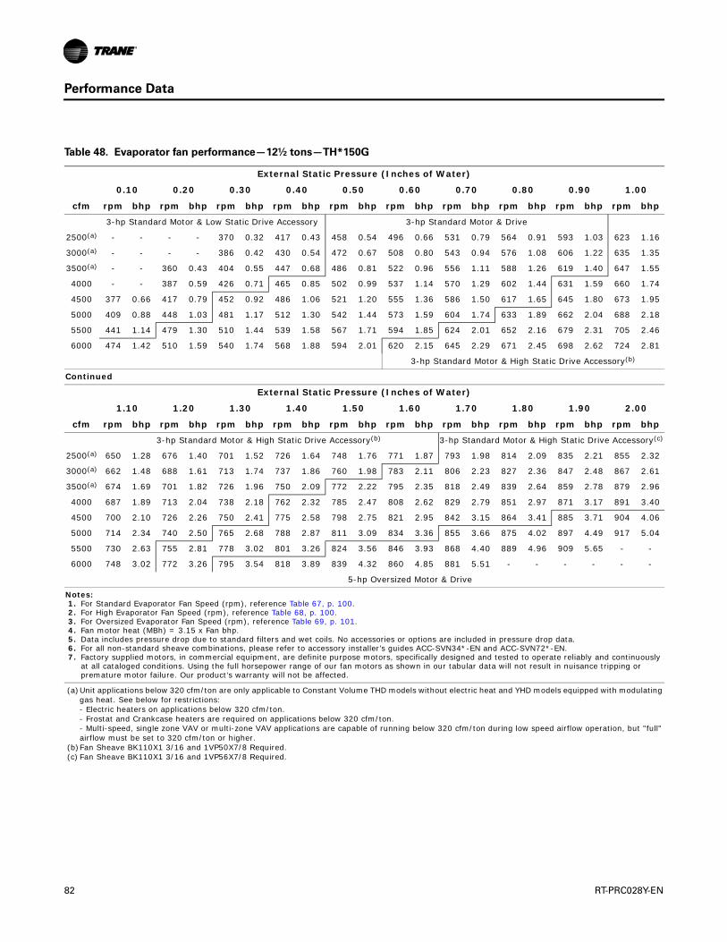
Performance Data
Table 48. Evaporator fan performance—12½ tons—TH*150G
External Static Pressure (Inches of Water)
0.10 0.20 0.30 0.40 0.50 0.60 0.70 0.80 0.90 1.00
cfm rpm bhp rpm bhp rpm bhp rpm bhp rpm bhp rpm bhp rpm bhp rpm bhp rpm bhp rpm bhp
3-hp Standard Motor & Low Static Drive Accessory 3-hp Standard Motor & Drive
2500(a) - - - - 370 0.32 417 0.43 458 0.54 496 0.66 531 0.79 564 0.91 593 1.03 623 1.16
3000(a) - - - - 386 0.42 430 0.54 472 0.67 508 0.80 543 0.94 576 1.08 606 1.22 635 1.35
3500(a) - - 360 0.43 404 0.55 447 0.68 486 0.81 522 0.96 556 1.11 588 1.26 619 1.40 647 1.55
4000 - - 387 0.59 426 0.71 465 0.85 502 0.99 537 1.14 570 1.29 602 1.44 631 1.59 660 1.74
4500 377 0.66 417 0.79 452 0.92 486 1.06 521 1.20 555 1.36 586 1.50 617 1.65 645 1.80 673 1.95
5000 409 0.88 448 1.03 481 1.17 512 1.30 542 1.44 573 1.59 604 1.74 633 1.89 662 2.04 688 2.18
5500 441 1.14 479 1.30 510 1.44 539 1.58 567 1.71 594 1.85 624 2.01 652 2.16 679 2.31 705 2.46
6000 474 1.42 510 1.59 540 1.74 568 1.88 594 2.01 620 2.15 645 2.29 671 2.45 698 2.62 724 2.81
3-hp Standard Motor & High Static Drive Accessory(b)
Continued
External Static Pressure (Inches of Water)
1.10 1.20 1.30 1.40 1.50 1.60 1.70 1.80 1.90 2.00
cfm rpm bhp rpm bhp rpm bhp rpm bhp rpm bhp rpm bhp rpm bhp rpm bhp rpm bhp rpm bhp
3-hp Standard Motor & High Static Drive Accessory(b) 3-hp Standard Motor & High Static Drive Accessory(c)
2500(a) 650 1.28 676 1.40 701 1.52 726 1.64 748 1.76 771 1.87 793 1.98 814 2.09 835 2.21 855 2.32
3000(a) 662 1.48 688 1.61 713 1.74 737 1.86 760 1.98 783 2.11 806 2.23 827 2.36 847 2.48 867 2.61
3500(a) 674 1.69 701 1.82 726 1.96 750 2.09 772 2.22 795 2.35 818 2.49 839 2.64 859 2.78 879 2.96
4000 687 1.89 713 2.04 738 2.18 762 2.32 785 2.47 808 2.62 829 2.79 851 2.97 871 3.17 891 3.40
4500 700 2.10 726 2.26 750 2.41 775 2.58 798 2.75 821 2.95 842 3.15 864 3.41 885 3.71 904 4.06
5000 714 2.34 740 2.50 765 2.68 788 2.87 811 3.09 834 3.36 855 3.66 875 4.02 897 4.49 917 5.04
5500 730 2.63 755 2.81 778 3.02 801 3.26 824 3.56 846 3.93 868 4.40 889 4.96 909 5.65 - -
6000 748 3.02 772 3.26 795 3.54 818 3.89 839 4.32 860 4.85 881 5.51 - - - - - -
5-hp Oversized Motor & Drive
Notes: 1. For Standard Evaporator Fan Speed (rpm), reference Table 67, p. 100. 2. For High Evaporator Fan Speed (rpm), reference Table 68, p. 100. 3. For Oversized Evaporator Fan Speed (rpm), reference Table 69, p. 101. 4. Fan motor heat (MBh) = 3.15 x Fan bhp. 5. Data includes pressure drop due to standard filters and wet coils. No accessories or options are included in pressure drop data. 6. For all non-standard sheave combinations, please refer to accessory installer’s guides ACC-SVN34*-EN and ACC-SVN72*-EN. 7. Factory supplied motors, in commercial equipment, are definite purpose motors, specifically designed and tested to operate reliably and continuously
at all cataloged conditions. Using the full horsepower range of our fan motors as shown in our tabular data will not result in nuisance tripping or premature motor failure. Our product’s warranty will not be affected.
(a)Unit applications below 320 cfm/ton are only applicable to Constant Volume THD models without electric heat and YHD models equipped with modulating gas heat. See below for restrictions:- Electric heaters on applications below 320 cfm/ton.- Frostat and Crankcase heaters are required on applications below 320 cfm/ton.- Multi-speed, single zone VAV or multi-zone VAV applications are capable of running below 320 cfm/ton during low speed airflow operation, but "full" airflow must be set to 320 cfm/ton or higher.
(b)Fan Sheave BK110X1 3/16 and 1VP50X7/8 Required.(c) Fan Sheave BK110X1 3/16 and 1VP56X7/8 Required.
82 RT-PRC028Y-EN

Performance Data
Table 49. Evaporator fan performance—12½ tons—THD150G—dehumidification (hot gas reheat) option
External Static Pressure (Inches of Water)
0.10 0.20 0.30 0.40 0.50 0.60 0.70 0.80 0.90 1.00
cfm rpm bhp rpm bhp rpm bhp rpm bhp rpm bhp rpm bhp rpm bhp rpm bhp rpm bhp rpm bhp
3-hp Standard Motor & Low Static Drive Accessory 3-hp Standard Motor & Drive
2500(a) — — — — 369 0.32 416 0.42 458 0.52 496 0.63 530 0.74 561 0.85 591 0.97 618 1.09
3000(a) — — — — 383 0.41 429 0.52 470 0.64 508 0.76 543 0.88 575 1.01 606 1.13 634 1.26
3500(a) — — 358 0.42 403 0.53 444 0.64 484 0.77 520 0.90 554 1.04 587 1.18 618 1.32 647 1.47
4000 — — 386 0.57 424 0.67 464 0.80 500 0.93 535 1.07 569 1.21 600 1.36 629 1.52 658 1.69
4500 375 0.62 415 0.75 450 0.86 484 0.99 519 1.13 552 1.28 583 1.42 615 1.58 644 1.75 671 1.92
5000 407 0.82 446 0.97 479 1.09 510 1.22 540 1.37 572 1.53 602 1.69 630 1.84 658 2.01 686 2.20
5500 440 1.06 477 1.22 508 1.37 537 1.50 565 1.65 592 1.81 621 1.99 650 2.16 676 2.34 701 2.51
6000 471 1.34 508 1.52 538 1.69 566 1.84 592 1.99 617 2.15 643 2.32 669 2.51 695 2.71 721 2.90
3-hp Standard Motor & High Static Drive Accessory(b)
Continued
External Static Pressure (Inches of Water)
1.10 1.20 1.30 1.40 1.50 1.60 1.70 1.80 1.90 2.00
cfm rpm bhp rpm bhp rpm bhp rpm bhp rpm bhp rpm bhp rpm bhp rpm bhp rpm bhp rpm bhp
3-hp Standard Motor & High Static Drive Accessory(b) 3-hp Standard Motor & High Static Drive Accessory(c)
2500(a) 645 1.22 670 1.35 694 1.48 718 1.61 740 1.75 762 1.88 783 2.02 803 2.17 823 2.31 843 2.46
3000(a) 660 1.40 686 1.54 710 1.69 733 1.83 755 1.98 777 2.13 798 2.28 819 2.44 839 2.60 858 2.76
3500(a) 674 1.61 700 1.76 725 1.91 749 2.07 771 2.23 793 2.39 814 2.56 834 2.73 854 2.90 873 3.07
4000 686 1.85 712 2.02 737 2.18 762 2.35 785 2.51 808 2.68 830 2.86 850 3.04 870 3.22 889 3.41
4500 698 2.10 724 2.28 749 2.47 773 2.65 797 2.84 820 3.02 842 3.21 863 3.39 884 3.58 904 3.77
5000 712 2.38 737 2.57 762 2.76 785 2.97 809 3.17 831 3.38 853 3.58 875 3.79 895 3.99 916 4.20
5500 727 2.70 753 2.90 776 3.10 799 3.31 822 3.52 844 3.74 865 3.96 886 4.19 907 4.42 927 4.64
6000 744 3.09 767 3.28 791 3.49 815 3.71 837 3.92 858 4.15 879 4.37 899 4.60 919 4.84 939 5.08
5-hp Oversized Motor & Drive
Notes: 1. For Standard Evaporator Fan Speed (rpm), reference Table 67, p. 100. 2. For High Evaporator Fan Speed (rpm), reference Table 68, p. 100. 3. For Oversized Evaporator Fan Speed (rpm), reference Table 69, p. 101. 4. Fan motor heat (MBh) = 3.15 x Fan bhp. 5. Data includes pressure drop due to standard filters and wet coils. No accessories or options are included in pressure drop data. 6. For all non-standard sheave combinations, please refer to accessory installer’s guides ACC-SVN34*-EN and ACC-SVN72*-EN. 7. Factory supplied motors, in commercial equipment, are definite purpose motors, specifically designed and tested to operate reliably and continuously
at all cataloged conditions. Using the full horsepower range of our fan motors as shown in our tabular data will not result in nuisance tripping or premature motor failure. Our product’s warranty will not be affected.
(a)Unit applications below 320 cfm/ton are only applicable to Constant Volume THD models without electric heat and YHD models equipped with modulating gas heat. See below for restrictions:- Electric heaters on applications below 320 cfm/ton.- Frostat and Crankcase heaters are required on applications below 320 cfm/ton.- Multi-speed, single zone VAV or multi-zone VAV applications are capable of running below 320 cfm/ton during low speed airflow operation, but "full" airflow must be set to 320 cfm/ton or higher.
(b)Fan Sheave BK110X1 3/16 and 1VP50X7/8 Required.(c) Fan Sheave BK110X1 3/16 and 1VP56X7/8 Required.
RT-PRC028Y-EN 83

Performance Data
Table 50. Evaporator fan performance—12½ tons—YH*150G
External Static Pressure (Inches of Water)
0.10 0.20 0.30 0.40 0.50 0.60 0.70 0.80 0.90 1.00
cfm rpm bhp rpm bhp rpm bhp rpm bhp rpm bhp rpm bhp rpm bhp rpm bhp rpm bhp rpm bhp
3-hp Standard Motor & Low Static Drive Accessory 3-hp Standard Motor & Drive
2500(a) 263 0.15 322 0.23 375 0.33 421 0.44 463 0.56 501 0.68 536 0.80 568 0.92 599 1.04 627 1.16
3000(a) 292 0.23 344 0.33 393 0.43 436 0.55 477 0.69 515 0.82 549 0.96 582 1.10 612 1.23 640 1.36
3500(a) 324 0.35 369 0.45 413 0.57 455 0.71 494 0.84 529 0.99 563 1.14 595 1.29 626 1.43 655 1.57
4000 358 0.51 398 0.62 437 0.75 475 0.89 512 1.03 547 1.18 579 1.33 609 1.48 639 1.63 668 1.78
4500 392 0.71 429 0.84 464 0.97 499 1.11 532 1.25 566 1.41 597 1.55 627 1.70 655 1.85 682 2.00
5000 427 0.95 462 1.09 493 1.22 525 1.36 556 1.51 587 1.66 617 1.80 645 1.95 673 2.10 700 2.25
5500 462 1.23 496 1.38 525 1.51 553 1.64 582 1.79 610 1.93 638 2.08 666 2.23 692 2.38 718 2.54
6000 497 1.53 530 1.69 558 1.83 584 1.96 610 2.09 636 2.24 662 2.39 688 2.56 713 2.73 738 2.92
3-hp Standard Motor & High Static Drive Accessory(b)
Continued
External Static Pressure (Inches of Water)
1.10 1.20 1.30 1.40 1.50 1.60 1.70 1.80 1.90 2.00
cfm rpm bhp rpm bhp rpm bhp rpm bhp rpm bhp rpm bhp rpm bhp rpm bhp rpm bhp rpm bhp
3-hp Standard Motor & High Static Drive Accessory(b) 3-hp Standard Motor & High Static Drive Accessory(c)
2500(a) 655 1.28 681 1.40 706 1.51 730 1.63 754 1.74 776 1.85 798 1.96 820 2.07 839 2.17 860 2.28
3000(a) 668 1.49 694 1.62 719 1.74 743 1.87 766 1.98 790 2.11 811 2.22 833 2.35 852 2.46 873 2.59
3500(a) 681 1.71 708 1.85 732 1.97 756 2.10 780 2.24 803 2.37 824 2.50 846 2.65 866 2.79 887 2.96
4000 695 1.93 721 2.07 746 2.22 770 2.36 794 2.50 816 2.66 838 2.82 859 3.00 879 3.20 899 3.44
4500 708 2.15 735 2.31 760 2.47 784 2.63 807 2.81 830 3.01 852 3.24 873 3.50 893 3.79 913 4.18
5000 725 2.41 750 2.57 773 2.75 798 2.97 821 3.20 843 3.47 865 3.81 887 4.22 907 4.71 926 5.27
5500 744 2.73 767 2.92 790 3.14 813 3.41 836 3.75 857 4.16 878 4.65 900 5.31 920 6.07 940 7.01
6000 761 3.14 786 3.42 809 3.74 831 4.15 852 4.64 873 5.25 894 6.07 913 6.97 934 8.19 954 9.61
5-hp Oversized Motor & Drive
Notes: 1. For Standard Evaporator Fan Speed (rpm), reference Table 67, p. 100. 2. For High Evaporator Fan Speed (rpm), reference Table 68, p. 100. 3. For Oversized Evaporator Fan Speed (rpm), reference Table 69, p. 101. 4. Fan motor heat (MBh) = 3.15 x Fan bhp. 5. Data includes pressure drop due to standard filters and wet coils. No accessories or options are included in pressure drop data. 6. For all non-standard sheave combinations, please refer to accessory installer’s guides ACC-SVN34*-EN and ACC-SVN72*-EN. 7. Refer to Table 70, p. 101 to determine additional static pressure drop due to other options/accessories. 8. Factory supplied motors, in commercial equipment, are definite purpose motors, specifically designed and tested to operate reliably and continuously
at all cataloged conditions. Using the full horsepower range of our fan motors as shown in our tabular data will not result in nuisance tripping or premature motor failure. Our product’s warranty will not be affected.
(a)Unit applications below 320 cfm/ton are only applicable to Constant Volume THD models without electric heat and YHD models equipped with modulating gas heat. See below for restrictions:- Electric heaters on applications below 320 cfm/ton.- Frostat and Crankcase heaters are required on applications below 320 cfm/ton.- Multi-speed, single zone VAV or multi-zone VAV applications are capable of running below 320 cfm/ton during low speed airflow operation, but "full" airflow must be set to 320 cfm/ton or higher.
(b)Fan Sheave BK110X1 3/16 and 1VP50X7/8 Required.(c) Fan Sheave BK110X1 3/16 and 1VP56X7/8 Required.
84 RT-PRC028Y-EN
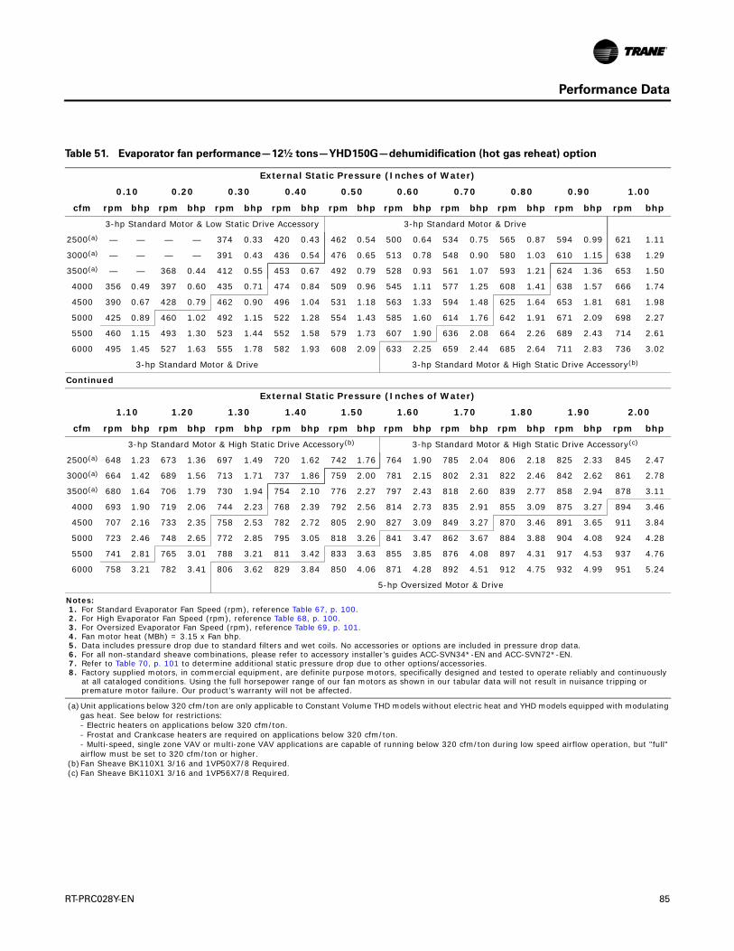
Performance Data
Table 51. Evaporator fan performance—12½ tons—YHD150G—dehumidification (hot gas reheat) option
External Static Pressure (Inches of Water)
0.10 0.20 0.30 0.40 0.50 0.60 0.70 0.80 0.90 1.00
cfm rpm bhp rpm bhp rpm bhp rpm bhp rpm bhp rpm bhp rpm bhp rpm bhp rpm bhp rpm bhp
3-hp Standard Motor & Low Static Drive Accessory 3-hp Standard Motor & Drive
2500(a) — — — — 374 0.33 420 0.43 462 0.54 500 0.64 534 0.75 565 0.87 594 0.99 621 1.11
3000(a) — — — — 391 0.43 436 0.54 476 0.65 513 0.78 548 0.90 580 1.03 610 1.15 638 1.29
3500(a) — — 368 0.44 412 0.55 453 0.67 492 0.79 528 0.93 561 1.07 593 1.21 624 1.36 653 1.50
4000 356 0.49 397 0.60 435 0.71 474 0.84 509 0.96 545 1.11 577 1.25 608 1.41 638 1.57 666 1.74
4500 390 0.67 428 0.79 462 0.90 496 1.04 531 1.18 563 1.33 594 1.48 625 1.64 653 1.81 681 1.98
5000 425 0.89 460 1.02 492 1.15 522 1.28 554 1.43 585 1.60 614 1.76 642 1.91 671 2.09 698 2.27
5500 460 1.15 493 1.30 523 1.44 552 1.58 579 1.73 607 1.90 636 2.08 664 2.26 689 2.43 714 2.61
6000 495 1.45 527 1.63 555 1.78 582 1.93 608 2.09 633 2.25 659 2.44 685 2.64 711 2.83 736 3.02
3-hp Standard Motor & Drive 3-hp Standard Motor & High Static Drive Accessory(b)
Continued
External Static Pressure (Inches of Water)
1.10 1.20 1.30 1.40 1.50 1.60 1.70 1.80 1.90 2.00
cfm rpm bhp rpm bhp rpm bhp rpm bhp rpm bhp rpm bhp rpm bhp rpm bhp rpm bhp rpm bhp
3-hp Standard Motor & High Static Drive Accessory(b) 3-hp Standard Motor & High Static Drive Accessory(c)
2500(a) 648 1.23 673 1.36 697 1.49 720 1.62 742 1.76 764 1.90 785 2.04 806 2.18 825 2.33 845 2.47
3000(a) 664 1.42 689 1.56 713 1.71 737 1.86 759 2.00 781 2.15 802 2.31 822 2.46 842 2.62 861 2.78
3500(a) 680 1.64 706 1.79 730 1.94 754 2.10 776 2.27 797 2.43 818 2.60 839 2.77 858 2.94 878 3.11
4000 693 1.90 719 2.06 744 2.23 768 2.39 792 2.56 814 2.73 835 2.91 855 3.09 875 3.27 894 3.46
4500 707 2.16 733 2.35 758 2.53 782 2.72 805 2.90 827 3.09 849 3.27 870 3.46 891 3.65 911 3.84
5000 723 2.46 748 2.65 772 2.85 795 3.05 818 3.26 841 3.47 862 3.67 884 3.88 904 4.08 924 4.28
5500 741 2.81 765 3.01 788 3.21 811 3.42 833 3.63 855 3.85 876 4.08 897 4.31 917 4.53 937 4.76
6000 758 3.21 782 3.41 806 3.62 829 3.84 850 4.06 871 4.28 892 4.51 912 4.75 932 4.99 951 5.24
5-hp Oversized Motor & Drive
Notes: 1. For Standard Evaporator Fan Speed (rpm), reference Table 67, p. 100. 2. For High Evaporator Fan Speed (rpm), reference Table 68, p. 100. 3. For Oversized Evaporator Fan Speed (rpm), reference Table 69, p. 101. 4. Fan motor heat (MBh) = 3.15 x Fan bhp. 5. Data includes pressure drop due to standard filters and wet coils. No accessories or options are included in pressure drop data. 6. For all non-standard sheave combinations, please refer to accessory installer’s guides ACC-SVN34*-EN and ACC-SVN72*-EN. 7. Refer to Table 70, p. 101 to determine additional static pressure drop due to other options/accessories. 8. Factory supplied motors, in commercial equipment, are definite purpose motors, specifically designed and tested to operate reliably and continuously
at all cataloged conditions. Using the full horsepower range of our fan motors as shown in our tabular data will not result in nuisance tripping or premature motor failure. Our product’s warranty will not be affected.
(a)Unit applications below 320 cfm/ton are only applicable to Constant Volume THD models without electric heat and YHD models equipped with modulating gas heat. See below for restrictions:- Electric heaters on applications below 320 cfm/ton.- Frostat and Crankcase heaters are required on applications below 320 cfm/ton.- Multi-speed, single zone VAV or multi-zone VAV applications are capable of running below 320 cfm/ton during low speed airflow operation, but "full" airflow must be set to 320 cfm/ton or higher.
(b)Fan Sheave BK110X1 3/16 and 1VP50X7/8 Required.(c) Fan Sheave BK110X1 3/16 and 1VP56X7/8 Required.
RT-PRC028Y-EN 85

Performance Data
Table 52. Evaporator fan performance—15 tons—TH*180G
External Static Pressure (Inches of Water)
0.10 0.20 0.30 0.40 0.50 0.60 0.70 0.80 0.90 1.00
cfm rpm bhp rpm bhp rpm bhp rpm bhp rpm bhp rpm bhp rpm bhp rpm bhp rpm bhp rpm bhp
3-hp Standard Motor & Low Static Drive Accessory 3-hp Standard Motor & Drive
3000(a) - - - - 369 0.38 411 0.47 448 0.57 483 0.68 514 0.78 543 0.89 570 1.00 596 1.11
3600(a) - - - - 391 0.50 429 0.61 465 0.72 499 0.84 530 0.96 560 1.08 587 1.21 614 1.33
4200(a) - - 378 0.55 416 0.66 451 0.78 485 0.90 516 1.03 547 1.16 575 1.30 603 1.44 629 1.58
4800 370 0.62 408 0.74 443 0.87 476 0.99 507 1.12 537 1.26 565 1.40 593 1.55 619 1.71 645 1.86
5400 405 0.84 439 0.97 472 1.11 502 1.25 532 1.39 560 1.54 587 1.69 613 1.85 638 2.01 662 2.18
6000 440 1.11 472 1.25 502 1.40 531 1.56 558 1.72 584 1.87 610 2.03 635 2.20 659 2.37 682 2.54
6600 476 1.43 505 1.58 533 1.74 560 1.92 586 2.09 611 2.26 635 2.44 659 2.61 682 2.79 704 2.97
7200 512 1.81 539 1.98 565 2.15 590 2.33 615 2.52 639 2.71 661 2.90 683 3.08 706 3.28 727 3.47
3-hp Standard Motor & High Static Drive Accessory(b)
5-hp Oversized Motor & Drive
Continued
External Static Pressure (Inches of Water)
1.10 1.20 1.30 1.40 1.50 1.60 1.70 1.80 1.90 2.00
cfm rpm bhp rpm bhp rpm bhp rpm bhp rpm bhp rpm bhp rpm bhp rpm bhp rpm bhp rpm bhp
3-hp Standard Motor & High Static Drive Accessory(b) 3HP Standard Motor & High Static Drive Accessory(c)
3000(a) 620 1.23 643 1.35 664 1.47 684 1.59 703 1.72 722 1.86 740 1.99 757 2.13 775 2.27 791 2.41
3600(a) 638 1.46 662 1.59 684 1.73 705 1.86 726 2.00 746 2.14 765 2.28 784 2.42 801 2.57 817 2.72
4200(a) 654 1.73 678 1.87 701 2.02 723 2.17 744 2.32 764 2.47 784 2.62 802 2.78 821 2.94 839 3.10
4800 670 2.02 693 2.18 716 2.34 738 2.51 760 2.67 780 2.84 800 3.01 820 3.18 838 3.35 856 3.52
5400 686 2.35 709 2.52 732 2.70 753 2.88 775 3.06 795 3.24 815 3.42 835 3.61 854 3.80 872 3.98
6000 705 2.73 727 2.91 749 3.10 770 3.29 790 3.48 810 3.68 830 3.88 850 4.08 869 4.28 887 4.48
6600 725 3.16 747 3.35 767 3.55 788 3.75 808 3.96 827 4.17 846 4.37 865 4.59 884 4.80 902 5.02
7200 748 3.66 768 3.86 788 4.07 808 4.28 827 4.49 846 4.71 864 4.93 883 5.15 900 5.38 918 5.61
5-hp Oversized Motor & Drive
Notes: 1. For Standard Evaporator Fan Speed (rpm), reference Table 67, p. 100. 2. For High Evaporator Fan Speed (rpm), reference Table 68, p. 100. 3. For Oversized Evaporator Fan Speed (rpm), reference Table 69, p. 101. 4. Fan motor heat (MBh) = 3.15 x Fan bhp. 5. Data includes pressure drop due to standard filters and wet coils. No accessories or options are included in pressure drop data. 6. For all non-standard sheave combinations, please refer to accessory installer’s guides ACC-SVN34*-EN and ACC-SVN72*-EN. 7. Factory supplied motors, in commercial equipment, are definite purpose motors, specifically designed and tested to operate reliably and continuously
at all cataloged conditions. Using the full horsepower range of our fan motors as shown in our tabular data will not result in nuisance tripping or premature motor failure. Our product’s warranty will not be affected.
(a)Unit applications below 320 cfm/ton are only applicable to Constant Volume THD models without electric heat and YHD models equipped with modulating gas heat. See below for restrictions:- Electric heaters on applications below 320 cfm/ton.- Frostat and Crankcase heaters are required on applications below 320 cfm/ton.- Multi-speed, single zone VAV or multi-zone VAV applications are capable of running below 320 cfm/ton during low speed airflow operation, but "full" airflow must be set to 320 cfm/ton or higher.
(b)Fan Sheave BK110X1 3/16 and 1VP50X7/8 Required.(c) Fan Sheave BK110X1 3/16 and 1VP56X7/8 Required.
86 RT-PRC028Y-EN

Performance Data
d h )
ll r
w
Table 53. Evaporator fan performance—15 tons—THD180G—dehumidification (hot gas reheat) option
External Static Pressure (Inches of Water)
0.10 0.20 0.30 0.40 0.50 0.60 0.70 0.80 0.90 1.00
cfm rpm bhp rpm bhp rpm bhp rpm bhp rpm bhp rpm bhp rpm bhp rpm bhp rpm bhp rpm bhp
3-hp Standard Motor & Low Static Drive Accessory 3-hp Standard Motor & Drive
3000(a) — — — — — — 387 0.49 424 0.61 458 0.72 489 0.84 516 0.96 541 1.08 565 1.20
3600(a) — — — — 367 0.51 407 0.63 441 0.76 472 0.89 502 1.02 532 1.16 559 1.30 584 1.44
4200(a) — — 354 0.54 391 0.67 426 0.80 460 0.94 492 1.08 520 1.23 546 1.38 572 1.54 598 1.70
4800 — — 383 0.73 418 0.86 449 1.01 480 1.15 510 1.31 540 1.48 567 1.65 591 1.81 614 1.98
5400 371 0.82 412 0.97 446 1.11 476 1.26 504 1.43 531 1.59 558 1.76 585 1.94 611 2.13 635 2.32
6000 403 1.08 441 1.25 475 1.41 504 1.57 530 1.74 555 1.93 580 2.11 604 2.29 629 2.48 653 2.69
6600 435 1.39 472 1.59 504 1.78 532 1.94 558 2.12 582 2.31 605 2.51 628 2.71 650 2.91 672 3.11
7200 467 1.75 502 1.98 533 2.19 561 2.38 587 2.56 610 2.76 632 2.97 653 3.19 674 3.41 694 3.62
3-hp Standard Motor & High Static Drive Accessory(b) 5-hp Oversized Motor & Drive
Continued
External Static Pressure (Inches of Water)
1.10 1.20 1.30 1.40 1.50 1.60 1.70 1.80 1.90 2.00
cfm rpm bhp rpm bhp rpm bhp rpm bhp rpm bhp rpm bhp rpm bhp rpm bhp rpm bhp rpm bhp
3-hp Standard Motor & Drive
3-hp Standard Motor & High Static Drive Accessory(b)
3-hp StandarMotor & HigStatic DriveAccessory(c
3000(a) 587 1.32 609 1.44 629 1.57 649 1.70 668 1.83 687 1.97 705 2.11 723 2.25 740 2.39 758 2.54
3600(a) 608 1.58 629 1.72 650 1.87 670 2.01 689 2.16 708 2.30 725 2.45 743 2.61 760 2.76 776 2.92
4200(a) 623 1.86 647 2.03 669 2.19 690 2.36 709 2.52 728 2.68 746 2.85 764 3.01 781 3.18 797 3.35
4800 636 2.16 659 2.34 682 2.52 704 2.71 726 2.90 746 3.09 765 3.28 783 3.46 801 3.65 817 3.83
5400 656 2.51 677 2.70 698 2.89 717 3.09 738 3.29 758 3.50 778 3.71 798 3.92 817 4.13 835 4.34
6000 676 2.90 698 3.11 718 3.32 737 3.53 756 3.74 774 3.95 792 4.17 810 4.40 829 4.63 847 4.86
6600 694 3.33 716 3.56 737 3.79 758 4.02 777 4.25 795 4.48 812 4.71 829 4.94 846 5.18 862 5.42
7200 715 3.84 735 4.06 755 4.30 775 4.55 795 4.80 814 5.05 833 5.31 849.90 5.56 — — — —
5-hp Oversized Motor & Drive
Notes: 1. For Standard Evaporator Fan Speed (rpm), reference Table 67, p. 100. 2. For High Evaporator Fan Speed (rpm), reference Table 68, p. 100. 3. For Oversized Evaporator Fan Speed (rpm), reference Table 69, p. 101. 4. Fan motor heat (MBh) = 3.15 x Fan bhp. 5. Data includes pressure drop due to standard filters and wet coils. No accessories or options are included in pressure drop data. 6. For all non-standard sheave combinations, please refer to accessory installer’s guides ACC-SVN34*-EN and ACC-SVN72*-EN. 7. Factory supplied motors, in commercial equipment, are definite purpose motors, specifically designed and tested to operate reliably and continuously at a
cataloged conditions. Using the full horsepower range of our fan motors as shown in our tabular data will not result in nuisance tripping or premature motofailure. Our product’s warranty will not be affected.
(a)Unit applications below 320 cfm/ton are only applicable to Constant Volume THD models without electric heat and YHD models equipped with modulatinggas heat. See below for restrictions:- Electric heaters on applications below 320 cfm/ton.- Frostat and Crankcase heaters are required on applications below 320 cfm/ton.- Multi-speed, single zone VAV or multi-zone VAV applications are capable of running below 320 cfm/ton during low speed airflow operation, but "full" airflomust be set to 320 cfm/ton or higher.
(b)Fan Sheave BK110X1 3/16 and 1VP50X7/8 Required.(c) Fan Sheave BK110X1 3/16 and 1VP56X7/8 Required.
RT-PRC028Y-EN 87
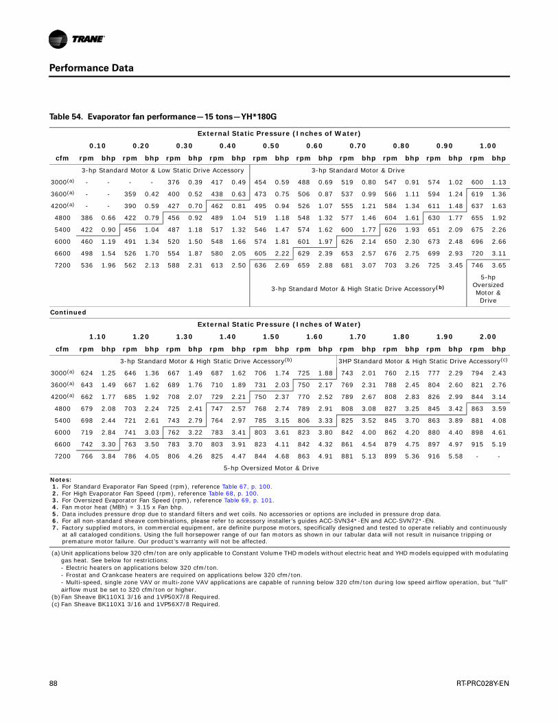
Performance Data
Table 54. Evaporator fan performance—15 tons—YH*180G
External Static Pressure (Inches of Water)
0.10 0.20 0.30 0.40 0.50 0.60 0.70 0.80 0.90 1.00
cfm rpm bhp rpm bhp rpm bhp rpm bhp rpm bhp rpm bhp rpm bhp rpm bhp rpm bhp rpm bhp
3-hp Standard Motor & Low Static Drive Accessory 3-hp Standard Motor & Drive
3000(a) - - - - 376 0.39 417 0.49 454 0.59 488 0.69 519 0.80 547 0.91 574 1.02 600 1.13
3600(a) - - 359 0.42 400 0.52 438 0.63 473 0.75 506 0.87 537 0.99 566 1.11 594 1.24 619 1.36
4200(a) - - 390 0.59 427 0.70 462 0.81 495 0.94 526 1.07 555 1.21 584 1.34 611 1.48 637 1.63
4800 386 0.66 422 0.79 456 0.92 489 1.04 519 1.18 548 1.32 577 1.46 604 1.61 630 1.77 655 1.92
5400 422 0.90 456 1.04 487 1.18 517 1.32 546 1.47 574 1.62 600 1.77 626 1.93 651 2.09 675 2.26
6000 460 1.19 491 1.34 520 1.50 548 1.66 574 1.81 601 1.97 626 2.14 650 2.30 673 2.48 696 2.66
6600 498 1.54 526 1.70 554 1.87 580 2.05 605 2.22 629 2.39 653 2.57 676 2.75 699 2.93 720 3.11
7200 536 1.96 562 2.13 588 2.31 613 2.50 636 2.69 659 2.88 681 3.07 703 3.26 725 3.45 746 3.65
3-hp Standard Motor & High Static Drive Accessory(b)
5-hp Oversized Motor & Drive
Continued
External Static Pressure (Inches of Water)
1.10 1.20 1.30 1.40 1.50 1.60 1.70 1.80 1.90 2.00
cfm rpm bhp rpm bhp rpm bhp rpm bhp rpm bhp rpm bhp rpm bhp rpm bhp rpm bhp rpm bhp
3-hp Standard Motor & High Static Drive Accessory(b) 3HP Standard Motor & High Static Drive Accessory(c)
3000(a) 624 1.25 646 1.36 667 1.49 687 1.62 706 1.74 725 1.88 743 2.01 760 2.15 777 2.29 794 2.43
3600(a) 643 1.49 667 1.62 689 1.76 710 1.89 731 2.03 750 2.17 769 2.31 788 2.45 804 2.60 821 2.76
4200(a) 662 1.77 685 1.92 708 2.07 729 2.21 750 2.37 770 2.52 789 2.67 808 2.83 826 2.99 844 3.14
4800 679 2.08 703 2.24 725 2.41 747 2.57 768 2.74 789 2.91 808 3.08 827 3.25 845 3.42 863 3.59
5400 698 2.44 721 2.61 743 2.79 764 2.97 785 3.15 806 3.33 825 3.52 845 3.70 863 3.89 881 4.08
6000 719 2.84 741 3.03 762 3.22 783 3.41 803 3.61 823 3.80 842 4.00 862 4.20 880 4.40 898 4.61
6600 742 3.30 763 3.50 783 3.70 803 3.91 823 4.11 842 4.32 861 4.54 879 4.75 897 4.97 915 5.19
7200 766 3.84 786 4.05 806 4.26 825 4.47 844 4.68 863 4.91 881 5.13 899 5.36 916 5.58 - -
5-hp Oversized Motor & Drive
Notes: 1. For Standard Evaporator Fan Speed (rpm), reference Table 67, p. 100. 2. For High Evaporator Fan Speed (rpm), reference Table 68, p. 100. 3. For Oversized Evaporator Fan Speed (rpm), reference Table 69, p. 101. 4. Fan motor heat (MBh) = 3.15 x Fan bhp. 5. Data includes pressure drop due to standard filters and wet coils. No accessories or options are included in pressure drop data. 6. For all non-standard sheave combinations, please refer to accessory installer’s guides ACC-SVN34*-EN and ACC-SVN72*-EN. 7. Factory supplied motors, in commercial equipment, are definite purpose motors, specifically designed and tested to operate reliably and continuously
at all cataloged conditions. Using the full horsepower range of our fan motors as shown in our tabular data will not result in nuisance tripping or premature motor failure. Our product’s warranty will not be affected.
(a)Unit applications below 320 cfm/ton are only applicable to Constant Volume THD models without electric heat and YHD models equipped with modulating gas heat. See below for restrictions:- Electric heaters on applications below 320 cfm/ton.- Frostat and Crankcase heaters are required on applications below 320 cfm/ton.- Multi-speed, single zone VAV or multi-zone VAV applications are capable of running below 320 cfm/ton during low speed airflow operation, but "full" airflow must be set to 320 cfm/ton or higher.
(b)Fan Sheave BK110X1 3/16 and 1VP50X7/8 Required.(c) Fan Sheave BK110X1 3/16 and 1VP56X7/8 Required.
88 RT-PRC028Y-EN

Performance Data
Table 55. Evaporator fan performance—15 tons—YHD180G—dehumidification (hot gas reheat) option
External Static Pressure (Inches of Water)
0.10 0.20 0.30 0.40 0.50 0.60 0.70 0.80 0.90 1.00
cfm rpm bhp rpm bhp rpm bhp rpm bhp rpm bhp rpm bhp rpm bhp rpm bhp rpm bhp rpm bhp
3-hp Standard Motor & Low Static Drive Accessory 3-hp Standard Motor & Drive
3000(a) — — — — 355 0.40 393 0.51 429 0.63 463 0.74 493 0.86 520 0.98 545 1.10 568 1.22
3600(a) — — — — 377 0.53 415 0.66 448 0.79 478 0.91 509 1.05 538 1.19 565 1.33 590 1.47
4200(a) — — 366 0.58 402 0.71 436 0.84 470 0.98 501 1.13 528 1.28 554 1.43 580 1.59 606 1.75
4800 358 0.66 397 0.78 430 0.92 461 1.07 492 1.21 522 1.38 551 1.54 576 1.71 600 1.88 623 2.05
5400 393 0.90 430 1.04 461 1.19 490 1.35 517 1.51 545 1.67 572 1.85 598 2.04 623 2.23 646 2.41
6000 428 1.19 463 1.35 493 1.51 520 1.68 546 1.86 571 2.04 595 2.22 619 2.41 644 2.61 667 2.82
6600 463 1.54 496 1.73 525 1.90 552 2.07 576 2.26 599 2.46 622 2.66 644 2.86 666 3.06 688 3.27
7200 499 1.96 531 2.18 559 2.36 584 2.55 607 2.74 630 2.95 651 3.17 672 3.38 692 3.60 713 3.82
3-hp Standard Motor & High Static Drive Accessory(b) 5-hp Oversized Motor & Drive
Continued
External Static Pressure (Inches of Water)
1.10 1.20 1.30 1.40 1.50 1.60 1.70 1.80 1.90 2.00
cfm rpm bhp rpm bhp rpm bhp rpm bhp rpm bhp rpm bhp rpm bhp rpm bhp rpm bhp rpm bhp
3-hp Standard Motor & Drive 3-hp Standard Motor & High Static Drive Accessory(b)
3HP Standard Motor & High Static Drive Accessory(c)
3000(a) 591 1.34 612 1.46 632 1.59 652 1.72 671 1.86 690 1.99 708 2.13 725 2.27 743 2.42 761 2.56
3600(a) 613 1.61 634 1.76 655 1.90 674 2.04 693 2.19 712 2.34 729 2.49 746 2.64 763 2.79 780 2.95
4200(a) 631 1.91 654 2.08 676 2.24 696 2.40 715 2.57 734 2.73 752 2.90 769 3.07 786 3.23 802 3.41
4800 645 2.23 668 2.41 691 2.60 713 2.79 734 2.98 754 3.16 772 3.35 790 3.54 807 3.72 824 3.91
5400 667 2.60 687 2.79 708 2.99 728 3.19 748 3.40 768 3.60 788 3.81 807 4.03 826 4.24 844 4.45
6000 690 3.03 711 3.24 730 3.45 749 3.66 767 3.87 785 4.09 803 4.31 822 4.54 840 4.77 858 5.00
6600 711 3.50 732 3.73 753 3.96 772 4.20 790 4.42 808 4.66 825 4.88 841 5.12 858 5.36 874 5.60
7200 733 4.04 753 4.28 773 4.52 793 4.77 812 5.02 831 5.28 848.25 5.53 — — — — — —
5-hp Oversized Motor & Drive
Notes: 1. For Standard Evaporator Fan Speed (rpm), reference Table 67, p. 100. 2. For High Evaporator Fan Speed (rpm), reference Table 68, p. 100. 3. For Oversized Evaporator Fan Speed (rpm), reference Table 69, p. 101. 4. Fan motor heat (MBh) = 3.15 x Fan bhp. 5. Data includes pressure drop due to standard filters and wet coils. No accessories or options are included in pressure drop data. 6. For all non-standard sheave combinations, please refer to accessory installer’s guides ACC-SVN34*-EN and ACC-SVN72*-EN. 7. Factory supplied motors, in commercial equipment, are definite purpose motors, specifically designed and tested to operate reliably and continuously at
all cataloged conditions. Using the full horsepower range of our fan motors as shown in our tabular data will not result in nuisance tripping or premature motor failure. Our product’s warranty will not be affected.
(a)Unit applications below 320 cfm/ton are only applicable to Constant Volume THD models without electric heat and YHD models equipped with modulating gas heat. See below for restrictions:- Electric heaters on applications below 320 cfm/ton.- Frostat and Crankcase heaters are required on applications below 320 cfm/ton.- Multi-speed, single zone VAV or multi-zone VAV applications are capable of running below 320 cfm/ton during low speed airflow operation, but "full" airflow must be set to 320 cfm/ton or higher.
(b)Fan Sheave BK110X1 3/16 and 1VP50X7/8 Required.(c) Fan Sheave BK110X1 3/16 and 1VP56X7/8 Required.
RT-PRC028Y-EN 89

Performance Data
Table 56. Evaporator fan performance— 17½ tons — TH*210G
External Static Pressure (Inches of Water)
0.10 0.20 0.30 0.40 0.50 0.60 0.70 0.80 0.90 1.00
cfm rpm bhp rpm bhp rpm bhp rpm bhp rpm bhp rpm bhp rpm bhp rpm bhp rpm bhp rpm bhp
5-hp Standard Motor & Low Static Drive Accessory
3500(a) — — — — — — — — — — 470 0.86 501 1.00 531 1.13 558 1.27 582 1.41
4200(a) — — — — — — — — 462 0.94 494 1.09 521 1.24 547 1.39 573 1.54 599 1.71
4900(a) — — — — — — 455 1.06 485 1.20 515 1.36 544 1.53 572 1.70 596 1.88 619 2.05
5600 — — — — 458 1.21 487 1.37 514 1.54 541 1.71 567 1.88 593 2.07 619 2.26 643 2.46
6300 — — 459 1.43 492 1.60 520 1.76 546 1.94 570 2.13 594 2.32 618 2.51 641 2.70 664 2.91
7000 460 1.65 495 1.86 526 2.07 554 2.24 580 2.42 603 2.63 625 2.83 646 3.05 668 3.25 689 3.47
7700 498 2.13 531 2.38 562 2.62 589 2.82 614 3.02 637 3.22 658 3.44 678 3.66 698 3.90 717 4.13
8400 537 2.71 568 2.99 597 3.26 624 3.50 648 3.71 670 3.93 692 4.15 711 4.38 730 4.63 748 4.88
5-hp Standard Motor & Drive 5-hp Standard Motor & High Static Drive Accessory
Continued
External Static Pressure (Inches of Water)
1.10 1.20 1.30 1.40 1.50 1.60 1.70 1.80 1.90 2.00
cfm rpm bhp rpm bhp rpm bhp rpm bhp rpm bhp rpm bhp rpm bhp rpm bhp rpm bhp rpm bhp
5-hp Standard Motor & Drive 5-hp Standard Motor & High Static Drive Accessory
3500(a) 605 1.54 627 1.68 648 1.82 667 1.96 686 2.11 705 2.25 723 2.40 740 2.55 757 2.70 773 2.86
4200(a) 624 1.87 648 2.04 670 2.20 691 2.36 710 2.53 729 2.69 747 2.86 765 3.03 782 3.19 798 3.36
4900(a) 641 2.22 663 2.41 686 2.59 708 2.79 729 2.98 750 3.17 769 3.36 788 3.55 805 3.74 822 3.93
5600 665 2.65 686 2.85 706 3.05 725 3.25 745 3.45 764 3.66 784 3.88 803 4.09 822 4.31 841 4.54
6300 687 3.13 709 3.35 730 3.57 750 3.79 768 4.01 786 4.23 804 4.46 821 4.69 838 4.92 856 5.15
7000 710 3.68 731 3.91 752 4.15 772 4.40 792 4.64 811 4.89 828 5.14 845 5.38 861 5.62 878 5.87
7700 737 4.36 756 4.59 775 4.83 794 5.07 813 5.33 832 5.60 850 5.87 868 6.14 886 6.41 902 6.68
8400 767 5.14 784 5.38 802 5.63 820 5.89 837 6.15 854 6.41 872 6.68 889 6.97 907 7.26 924 7.55
7.5-hp Oversized Motor & Drive
Notes: 1. For Standard Evaporator Fan Speed (rpm), reference Table 67, p. 100. 2. For High Evaporator Fan Speed (rpm), reference Table 68, p. 100. 3. For Oversized Evaporator Fan Speed (rpm), reference Table 69, p. 101. 4. Fan motor heat (MBh) = 3.15 x Fan bhp. 5. Data includes pressure drop due to standard filters and wet coils. No accessories or options are included in pressure drop data. 6. For all non-standard sheave combinations, please refer to accessory installer’s guides ACC-SVN34*-EN and ACC-SVN72*-EN. 7. Factory supplied motors, in commercial equipment, are definite purpose motors, specifically designed and tested to operate reliably and continuously
at all cataloged conditions. Using the full horsepower range of our fan motors as shown in our tabular data will not result in nuisance tripping or premature motor failure. Our product’s warranty will not be affected.
(a)Unit applications below 320 cfm/ton are only applicable to Constant Volume THD models without electric heat and YHD models equipped with modulating gas heat. See below for restrictions:- Electric heaters on applications below 320 cfm/ton.- Frostat and Crankcase heaters are required on applications below 320 cfm/ton.- Multi-speed, single zone VAV or multi-zone VAV applications are capable of running below 320 cfm/ton during low speed airflow operation, but "full" airflow must be set to 320 cfm/ton or higher.
90 RT-PRC028Y-EN

Performance Data
Table 57. Evaporator fan performance — 17½ tons — THD210G — dehumidification (hot gas reheat) option
External Static Pressure (Inches of Water)
0.10 0.20 0.30 0.40 0.50 0.60 0.70 0.80 0.90 1.00
cfm rpm bhp rpm bhp rpm bhp rpm bhp rpm bhp rpm bhp rpm bhp rpm bhp rpm bhp rpm bhp
5HP Standard Motor & Low Static Drive Accessory
5HP Standard Motor & Drive
3500(a) — — — — — — — — — — 470 0.86 501 1.00 531 1.13 558 1.27 582 1.41
4200(a) — — — — — — — — 462 0.94 494 1.09 521 1.24 547 1.39 573 1.54 599 1.71
4900(a) — — — — — — 455 1.06 485 1.20 515 1.36 544 1.53 572 1.70 596 1.88 619 2.05
5600 — — — — 458 1.21 487 1.37 514 1.54 541 1.71 567 1.88 593 2.07 619 2.26 643 2.46
6300 — — 459 1.43 492 1.60 520 1.76 546 1.94 570 2.13 594 2.32 618 2.51 641 2.70 664 2.91
7000 460 1.65 495 1.86 526 2.07 554 2.24 580 2.42 603 2.63 625 2.83 646 3.05 668 3.25 689 3.47
7700 498 2.13 531 2.38 562 2.62 589 2.82 614 3.02 637 3.22 658 3.44 678 3.66 698 3.90 717 4.13
8400 537 2.71 568 2.99 597 3.26 624 3.50 648 3.71 670 3.93 692 4.15 711 4.38 730 4.63 748 4.88
5HP Standard Motor & High Static Drive Accessory
Continued
External Static Pressure (Inches of Water)
1.10 1.20 1.30 1.40 1.50 1.60 1.70 1.80 1.90 2.00
cfm rpm bhp rpm bhp rpm bhp rpm bhp rpm bhp rpm bhp rpm bhp rpm bhp rpm bhp rpm bhp
5HP Standard Motor & Drive 5HP Standard Motor & High Static Drive Accessory
3500(a) 605 1.54 627 1.68 648 1.82 667 1.96 686 2.11 705 2.25 723 2.40 740 2.55 757 2.70 773 2.86
4200(a) 624 1.87 648 2.04 670 2.20 691 2.36 710 2.53 729 2.69 747 2.86 765 3.03 782 3.19 798 3.36
4900(a) 641 2.22 663 2.41 686 2.59 708 2.79 729 2.98 750 3.17 769 3.36 788 3.55 805 3.74 822 3.93
5600 665 2.65 686 2.85 706 3.05 725 3.25 745 3.45 764 3.66 784 3.88 803 4.09 822 4.31 841 4.54
6300 687 3.13 709 3.35 730 3.57 750 3.79 768 4.01 786 4.23 804 4.46 821 4.69 838 4.92 856 5.15
7000 710 3.68 731 3.91 752 4.15 772 4.40 792 4.64 811 4.89 828 5.14 845 5.38 861 5.62 878 5.87
7700 737 4.36 756 4.59 775 4.83 794 5.07 813 5.33 832 5.60 850 5.87 868 6.14 886 6.41 902 6.68
8400 767 5.14 784 5.38 802 5.63 820 5.89 837 6.15 854 6.41 872 6.68 889 6.97 907 7.26 924 7.55
7.5HP Oversized Motor & Drive
Notes: 1. For Standard Evaporator Fan Speed (rpm), reference Table 67, p. 100. 2. For High Evaporator Fan Speed (rpm), reference Table 68, p. 100. 3. For Oversized Evaporator Fan Speed (rpm), reference Table 69, p. 101. 4. Fan motor heat (MBh) = 3.15 x Fan bhp. 5. Data includes pressure drop due to standard filters and wet coils. No accessories or options are included in pressure drop data. 6. For all non-standard sheave combinations, please refer to accessory installer’s guides ACC-SVN34*-EN and ACC-SVN72*-EN. 7. Factory supplied motors, in commercial equipment, are definite purpose motors, specifically designed and tested to operate reliably and continuously
at all cataloged conditions. Using the full horsepower range of our fan motors as shown in our tabular data will not result in nuisance tripping or premature motor failure. Our product’s warranty will not be affected.
(a)Unit applications below 320 cfm/ton are only applicable to Constant Volume THD models without electric heat and YHD models equipped with modulating gas heat. See below for restrictions:- Electric heaters on applications below 320 cfm/ton.- Frostat and Crankcase heaters are required on applications below 320 cfm/ton.- Multi-speed, single zone VAV or multi-zone VAV applications are capable of running below 320 cfm/ton during low speed airflow operation, but "full" airflow must be set to 320 cfm/ton or higher.
RT-PRC028Y-EN 91

Performance Data
Table 58. Evaporator fan performance—17½ tons—YH*210G
External Static Pressure (Inches of Water)
0.10 0.20 0.30 0.40 0.50 0.60 0.70 0.80 0.90 1.00
cfm rpm bhp rpm bhp rpm bhp rpm bhp rpm bhp rpm bhp rpm bhp rpm bhp rpm bhp rpm bhp
5-hp Standard Motor & Low Static Drive Accessory 5-hp Standard Motor & Drive
3500(a) — — — — — — — — — — 476 0.89 508 1.02 537 1.16 563 1.30 587 1.43
4200(a) — — — — — — — — 472 0.99 502 1.14 529 1.28 555 1.43 581 1.59 607 1.76
4900(a) — — — — — — 468 1.12 497 1.27 527 1.43 556 1.60 582 1.78 605 1.95 628 2.12
5600 — — — — 474 1.29 501 1.46 528 1.63 555 1.80 581 1.98 607 2.17 632 2.37 655 2.56
6300 — — 482 1.55 512 1.71 538 1.88 563 2.07 587 2.26 610 2.45 634 2.64 657 2.84 680 3.06
7000 490 1.84 522 2.04 550 2.22 576 2.39 599 2.59 621 2.80 643 3.01 665 3.22 686 3.43 707 3.65
7700 532 2.39 562 2.62 589 2.83 614 3.02 637 3.22 658 3.44 679 3.67 698 3.90 718 4.13 737 4.36
8400 574 3.03 603 3.30 629 3.55 653 3.76 675 3.97 696 4.20 715 4.43 734 4.68 752 4.93 770 5.18
5-hp Standard Motor & High Static Drive Accessory
Continued
External Static Pressure (Inches of Water)
1.10 1.20 1.30 1.40 1.50 1.60 1.70 1.80 1.90 2.00
cfm rpm bhp rpm bhp rpm bhp rpm bhp rpm bhp rpm bhp rpm bhp rpm bhp rpm bhp rpm bhp
5-hp Standard Motor & Drive 5-hp Standard Motor & High Static Drive Accessory
3500(a) 610 1.57 631 1.71 652 1.85 672 1.99 690 2.14 709 2.28 726 2.43 744 2.58 760 2.73 777 2.89
4200(a) 632 1.92 655 2.09 677 2.25 697 2.41 716 2.58 735 2.74 753 2.91 770 3.08 787 3.24 803 3.42
4900(a) 650 2.30 673 2.48 695 2.67 717 2.86 738 3.06 758 3.25 777 3.44 795 3.63 812 3.82 829 4.01
5600 677 2.76 697 2.96 717 3.15 736 3.36 755 3.56 775 3.78 795 3.99 814 4.21 832 4.43 850 4.65
6300 702 3.28 724 3.50 744 3.72 762 3.94 781 4.17 798 4.39 816 4.61 833 4.84 850 5.08 868 5.32
7000 727 3.88 748 4.11 769 4.36 789 4.60 808 4.85 826 5.10 843 5.34 859 5.59 875 5.83 891 6.08
7700 756 4.59 775 4.83 794 5.08 813 5.34 832 5.60 851 5.87 869 6.15 886 6.41 903 6.69 918 6.96
8400 788 5.44 806 5.69 824 5.95 841 6.21 858 6.46 876 6.74 893 7.03 910 7.32 927 7.61 944 7.91
7.5-hp Oversized Motor & Drive
Notes: 1. For Standard Evaporator Fan Speed (rpm), reference Table 67, p. 100. 2. For High Evaporator Fan Speed (rpm), reference Table 68, p. 100. 3. For Oversized Evaporator Fan Speed (rpm), reference Table 69, p. 101. 4. Fan motor heat (MBh) = 3.15 x Fan bhp. 5. Data includes pressure drop due to standard filters and wet coils. No accessories or options are included in pressure drop data. 6. For all non-standard sheave combinations, please refer to accessory installer’s guides ACC-SVN34*-EN and ACC-SVN72*-EN. 7. Refer to Table 70, p. 101 to determine additional static pressure drop due to other options/accessories. 8. Factory supplied motors, in commercial equipment, are definite purpose motors, specifically designed and tested to operate reliably and continuously
at all cataloged conditions. Using the full horsepower range of our fan motors as shown in our tabular data will not result in nuisance tripping or premature motor failure. Our product’s warranty will not be affected.
(a)Unit applications below 320 cfm/ton are only applicable to Constant Volume THD models without electric heat and YHD models equipped with modulating gas heat. See below for restrictions:- Electric heaters on applications below 320 cfm/ton.- Frostat and Crankcase heaters are required on applications below 320 cfm/ton.- Multi-speed, single zone VAV or multi-zone VAV applications are capable of running below 320 cfm/ton during low speed airflow operation, but "full" airflow must be set to 320 cfm/ton or higher.
92 RT-PRC028Y-EN

Performance Data
Table 59. Evaporator fan performance — 17½ tons — YHD210G — dehumidification (hot gas reheat) option
External Static Pressure (Inches of Water)
0.10 0.20 0.30 0.40 0.50 0.60 0.70 0.80 0.90 1.00
cfm rpm bhp rpm bhp rpm bhp rpm bhp rpm bhp rpm bhp rpm bhp rpm bhp rpm bhp rpm bhp
5HP Standard Motor & Low Static Drive
Accessory5HP Standard Motor & Drive
5600 — — — — 474 1.29 501 1.46 528 1.63 555 1.80 581 1.98 607 2.17 632 2.37 655 2.56
6300 — — 482 1.55(a) 512 1.71 538 1.88 563 2.07 587 2.26 610 2.45 634 2.64 657 2.84 680 3.06
7000 490 1.84(a) 522 2.04 550 2.22 576 2.39 599 2.59 621 2.80 643 3.01 665 3.22 686 3.43 707 3.65
7700 532 2.39 562 2.62 589 2.83 614 3.02 637 3.22 658 3.44 679 3.67 698 3.90 718 4.13 737 4.36
8400 574 3.03 603 3.30 629 3.55 653 3.76 675 3.97 696 4.20 715 4.43 734 4.68 752 4.93 770 5.18
5HP Standard Motor & High Static Drive Accessory
Continued
External Static Pressure (Inches of Water)
1.10 1.20 1.30 1.40 1.50 1.60 1.70 1.80 1.90 2.00
cfm rpm bhp rpm bhp rpm bhp rpm bhp rpm bhp rpm bhp rpm bhp rpm bhp rpm bhp rpm bhp
5HP Standard Motor & High Static Drive Accessory
5600 677 2.76(b) 697 2.96 717 3.15 736 3.36 755 3.56 775 3.78 795 3.99 814 4.21 832 4.43 850 4.65
6300 702 3.28 724 3.50 744 3.72 762 3.94 781 4.17 798 4.39 816 4.61 833 4.84 850 5.08 868 5.32
7000 727 3.88 748 4.11 769 4.36 789 4.60 808 4.85 826 5.10 843 5.34 859 5.59 875 5.83 891 6.08
7700 756 4.59 775 4.83 794 5.08 813 5.34 832 5.60 851 5.87 869 6.15 886 6.41 903 6.69 918 6.96
8400 788 5.44 806 5.69 824 5.95 841 6.21 858 6.46 876 6.74 893 7.03 910 7.32 927 7.61 944 7.91
7.5HP Oversized Motor & Drive
Notes: 1. For Standard Evaporator Fan Speed (rpm), reference Table 67, p. 100. 2. For High Evaporator Fan Speed (rpm), reference Table 68, p. 100. 3. For Oversized Evaporator Fan Speed (rpm), reference Table 69, p. 101. 4. Fan motor heat (MBh) = 3.15 x Fan bhp. 5. Data includes pressure drop due to standard filters and wet coils. No accessories or options are included in pressure drop data. 6. For all non-standard sheave combinations, please refer to accessory installer’s guides ACC-SVN34*-EN and ACC-SVN72*-EN. 7. Refer to Table 70, p. 101 to determine additional static pressure drop due to other options/accessories. 8. Factory supplied motors, in commercial equipment, are definite purpose motors, specifically designed and tested to operate reliably and continuously at
all cataloged conditions. Using the full horsepower range of our fan motors as shown in our tabular data will not result in nuisance tripping or premature motor failure. Our product’s warranty will not be affected.
(a)5HP Standard Motor & Low Static Drive Accessory(b)5HP Standard Motor & Drive
RT-PRC028Y-EN 93

Performance Data
Table 60. Evaporator fan performance—20 tons—TH*240G
External Static Pressure (Inches of Water)
0.10 0.20 0.30 0.40 0.50 0.60 0.70 0.80 0.90 1.00
cfm rpm bhp rpm bhp rpm bhp rpm bhp rpm bhp rpm bhp rpm bhp rpm bhp rpm bhp rpm bhp
5-hp Standard Motor & Low Static Drive Accessory 5-hp Standard Motor & Drive
4000(a) — — — — — — — — 456 0.88 486 1.02 514 1.16 541 1.31 569 1.46 595 1.62
4800(a) — — — — — — 451 1.02 481 1.16 512 1.32 541 1.49 568 1.66 592 1.82 615 1.99
5600(a) — — — — 458 1.21 487 1.37 514 1.54 541 1.71 567 1.88 593 2.07 619 2.26 643 2.46
6400 — — 464 1.49 497 1.66 525 1.82 551 2.00 575 2.20 598 2.39 622 2.58 645 2.78 667 2.98
7200 470 1.77 505 2.00 536 2.21 564 2.40 589 2.58 612 2.78 634 3.00 655 3.21 676 3.43 697 3.65
8000 514 2.37 547 2.63 577 2.87 603 3.10 628 3.30 651 3.51 672 3.73 692 3.96 711 4.20 730 4.44
8800 560 3.10 590 3.38 618 3.65 644 3.92 667 4.16 690 4.39 711 4.61 731 4.84 749 5.09 767 5.35
9600 606 3.97 633 4.27 660 4.59 685 4.88 708 5.15 729 5.42 750 5.66 769 5.91 788 6.16 805 6.42
5-hp Standard Motor & High Static Drive Accessory 7.5-hp Oversized Motor & Field Supplied Motor Sheave(b)
Continued
External Static Pressure (Inches of Water)
1.10 1.20 1.30 1.40 1.50 1.60 1.70 1.80 1.90 2.00
cfm rpm bhp rpm bhp rpm bhp rpm bhp rpm bhp rpm bhp rpm bhp rpm bhp rpm bhp rpm bhp
5-hp Standard Motor & Drive 5-hp Standard Motor & High Static Drive Accessory
4000(a) 620 1.78 643 1.93 664 2.09 685 2.25 704 2.40 722 2.56 740 2.72 758 2.88 775 3.05 791 3.21
4800(a) 638 2.17 661 2.35 684 2.54 706 2.72 727 2.91 747 3.10 767 3.29 785 3.48 802 3.66 819 3.85
5600(a) 665 2.65 686 2.85 706 3.05 725 3.25 745 3.45 764 3.66 784 3.88 803 4.09 822 4.31 841 4.54
6400 690 3.20 712 3.43 733 3.65 753 3.88 772 4.10 790 4.32 807 4.55 824 4.78 841 5.01 858 5.25
7200 717 3.86 737 4.09 758 4.33 778 4.58 798 4.83 817 5.08 835 5.34 852 5.59 868 5.84 885 6.10
8000 749 4.68 768 4.92 786 5.16 804 5.41 823 5.66 841 5.93 859 6.20 877 6.48 895 6.76 912 7.04
8800 784 5.61 802 5.89(b) 819 6.15 836 6.41 853 6.67 869 6.95 886 7.21 902 7.49 919 7.78 936 8.09
9600 822 6.69 839 6.98 854 7.26 870 7.55 886 7.85 901 8.13 917 8.42 — — — — — —
7.5-hp Oversized Motor & Drive 7.5-hp Oversized Motor & Field Supplied Motor Sheave(c)
Notes: 1. For Standard Evaporator Fan Speed (rpm), reference Table 67, p. 100. 2. For High Evaporator Fan Speed (rpm), reference Table 68, p. 100. 3. For Oversized Evaporator Fan Speed (rpm), reference Table 69, p. 101. 4. Fan motor heat (MBh) = 3.15 x Fan bhp. 5. Field Supplied Fan Sheave BK190 Required. Field Supplied Belt may be necessary. 6. For all non-standard sheave combinations, please refer to accessory installer’s guides ACC-SVN34*-EN and ACC-SVN72*-EN. 7. Refer to Table 70, p. 101 to determine additional static pressure drop due to other options/accessories. 8. Data includes pressure drop due to standard filters and wet coils. No accessories or options are included in pressure drop data. 9. Factory supplied motors, in commercial equipment, are definite purpose motors, specifically designed and tested to operate reliably and continuously
at all cataloged conditions. Using the full horsepower range of our fan motors as shown in our tabular data will not result in nuisance tripping or premature motor failure. Our product’s warranty will not be affected.
(a)Unit applications below 320 cfm/ton are only applicable to Constant Volume THD models without electric heat and YHD models equipped with modulating gas heat. See below for restrictions:- Electric heaters on applications below 320 cfm/ton.- Frostat and Crankcase heaters are required on applications below 320 cfm/ton.- Multi-speed, single zone VAV or multi-zone VAV applications are capable of running below 320 cfm/ton during low speed airflow operation, but "full" airflow must be set to 320 cfm/ton or higher.
(b)7.5-hp Oversized Motor & Field Supplied Motor Sheave(c)
(c) Field supplied motor sheave 1VP50 x 1 1/8 required.
94 RT-PRC028Y-EN

Performance Data
Table 61. Evaporator fan performance—20 tons—THD240G—dehumidification (hot gas reheat) option
External Static Pressure (Inches of Water)
0.10 0.20 0.30 0.40 0.50 0.60 0.70 0.80 0.90 1.00
cfm rpm bhp rpm bhp rpm bhp rpm bhp rpm bhp rpm bhp rpm bhp rpm bhp rpm bhp rpm bhp
5-hp Standard Motor & Low Static Drive Accessory 5-hp Standard Motor & Drive
4000(a) — — — — — — — — 454 0.88 485 1.01 513 1.16 540 1.30 568 1.46 594 1.61
4800(a) — — — — — — 449 1.01 480 1.15 510 1.31 540 1.48 567 1.65 591 1.81 614 1.98
5600(a) — — — — 456 1.20 485 1.36 512 1.53 539 1.70 565 1.87 591 2.05 617 2.24 641 2.44
6400 — — 461 1.47 494 1.65 523 1.81 549 1.99 573 2.18 596 2.37 619 2.56 642 2.76 665 2.96
7200 467 1.75 502 1.98 533 2.19 561 2.38 587 2.56 610 2.76 632 2.97 653 3.19 674 3.41 694 3.62
8000 511 2.35 544 2.60 573 2.85 601 3.08 625 3.28 648 3.48 670 3.70 690 3.93 709 4.16 728 4.41
8800 556 3.06 586 3.34 614 3.62 640 3.89 664 4.13 687 4.36 708 4.58 728 4.80 746 5.05 764 5.31
9600 601 3.91 629 4.22 656 4.53 680 4.82 704 5.12 726 5.38 746 5.62 766 5.87 784 6.10 802 6.37
5-hp Standard Motor & High Static Drive Accessory 7.5-hp Oversized Motor & Field Supplied Motor Sheave(b)
Continued
External Static Pressure (Inches of Water)
1.10 1.20 1.30 1.40 1.50 1.60 1.70 1.80 1.90 2.00
cfm rpm bhp rpm bhp rpm bhp rpm bhp rpm bhp rpm bhp rpm bhp rpm bhp rpm bhp rpm bhp
5-hp Standard Motor & Drive 5-hp Standard Motor & High Static Drive Accessory
4000(a) 619 1.77 642 1.93 663 2.08 683 2.24 703 2.39 721 2.55 739 2.71 757 2.87 774 3.04 790 3.20
4800(a) 636 2.16 659 2.34 682 2.52 704 2.71 726 2.90 746 3.09 765 3.28 783 3.46 801 3.65 817 3.83
5600(a) 663 2.64 684 2.83 704 3.03 724 3.23 743 3.43 763 3.64 782 3.86 802 4.08 821 4.29 839 4.51
6400 688 3.18 710 3.40 731 3.63 751 3.85 770 4.08 788 4.30 805 4.52 822 4.75 839 4.98 856 5.22
7200 715 3.84 735 4.06 755 4.30 775 4.55 795 4.80 814 5.05 833 5.31 850 5.56 866 5.81 882 6.06
8000 747 4.65 765 4.89 784 5.12 802 5.37 820 5.62 838 5.89 856 6.16 874 6.44 892 6.71 909 7.00
8800 782 5.57 799 5.84(c) 816 6.10 833 6.36 850 6.63 866 6.89 883 7.16 899 7.44 916 7.73 933 8.03
9600 819 6.64 835 6.92 851 7.21 867 7.49 883 7.79 898 8.08 914 8.36 — — — — — —
7.5-hp Oversized Motor & Field Supplied Motor Sheave(b) 7.5-hp Oversized Motor & Drive
Notes: 1. For Standard Evaporator Fan Speed (rpm), reference Table 67, p. 100. 2. For High Evaporator Fan Speed (rpm), reference Table 68, p. 100. 3. For Oversized Evaporator Fan Speed (rpm), reference Table 69, p. 101. 4. Fan motor heat (MBh) = 3.15 x Fan bhp. 5. Data includes pressure drop due to standard filters and wet coils. No accessories or options are included in pressure drop data. 6. For all non-standard sheave combinations, please refer to accessory installer’s guides ACC-SVN34*-EN and ACC-SVN72*-EN. 7. Factory supplied motors, in commercial equipment, are definite purpose motors, specifically designed and tested to operate reliably and continuously
at all cataloged conditions. Using the full horsepower range of our fan motors as shown in our tabular data will not result in nuisance tripping or premature motor failure. Our product’s warranty will not be affected.
(a)Unit applications below 320 cfm/ton are only applicable to Constant Volume THD models without electric heat and YHD models equipped with modulating gas heat. See below for restrictions:- Electric heaters on applications below 320 cfm/ton.- Frostat and Crankcase heaters are required on applications below 320 cfm/ton.- Multi-speed, single zone VAV or multi-zone VAV applications are capable of running below 320 cfm/ton during low speed airflow operation, but "full" airflow must be set to 320 cfm/ton or higher.
(b)Field supplied motor sheave 1VP50 x 1 1/8 required.(c) 7.5-hp Oversized Motor & Field Supplied Motor Sheave(b)
RT-PRC028Y-EN 95

Performance Data
Table 62. Evaporator fan performance—20 tons—YH*240G
External Static Pressure (Inches of Water)
0.10 0.20 0.30 0.40 0.50 0.60 0.70 0.80 0.90 1.00
cfm rpm bhp rpm bhp rpm bhp rpm bhp rpm bhp rpm bhp rpm bhp rpm bhp rpm bhp rpm bhp
5-hp Standard Motor & Low Static Drive Accessory 5-hp Standard Motor & Drive
4000(a) — — — — — — — — 465 0.92 494 1.06 522 1.20 549 1.35 576 1.51 602 1.66
4800(a) — — — — — — 463 1.07 493 1.22 524 1.39 552 1.56 578 1.72 601 1.89 624 2.06
5600(a) — — — — 474 1.29 501 1.46 528 1.63 555 1.80 581 1.98 607 2.17 632 2.37 655 2.56
6400 454 1.43 487 1.61 517 1.77 544 1.95 568 2.14 591 2.33 615 2.52 638 2.72 661 2.92 684 3.14
7200 502 1.98 533 2.19 561 2.38 587 2.56 610 2.76 632 2.97 653 3.19 674 3.41 695 3.63 715 3.84
8000 550 2.64 579 2.89 606 3.12 631 3.32 653 3.53 674 3.75 694 3.98 713 4.22 732 4.47 751 4.70
8800 599 3.46 627 3.75 652 4.00 675 4.23 697 4.45 718 4.69 737 4.93 755 5.18 773 5.44 790 5.71
9600 648 4.44 674 4.74 698 5.04 721 5.33 742 5.56 761 5.80 780 6.05 798 6.30 815 6.58 832 6.86
5-hp Standard Motor & High Static Drive Accessory
7.5-hp Oversized Motor & Field Supplied Motor Sheave(b)
7.5-hp Oversized Motor & Drive
Continued
External Static Pressure (Inches of Water)
1.10 1.20 1.30 1.40 1.50 1.60 1.70 1.80 1.90 2.00
cfm rpm bhp rpm bhp rpm bhp rpm bhp rpm bhp rpm bhp rpm bhp rpm bhp rpm bhp rpm bhp
5-hp Standard Motor Drive 5-hp Standard Motor & High Static Drive Accessory
4000(a) 627 1.82 649 1.98 670 2.13 690 2.29 709 2.45 728 2.61 745 2.77 763 2.93 779 3.09 796 3.26
4800(a) 647 2.24 670 2.42 693 2.61 714 2.80 735 2.99 755 3.18 774 3.36 792 3.55 809 3.74 825 3.92
5600(a) 677 2.76 697 2.96 717 3.15 736 3.36 755 3.56 775 3.78 795 3.99 814 4.21 832 4.43 850 4.65
6400 706 3.36 727 3.58 748 3.81 766 4.03 784 4.26 802 4.48 819 4.71 836 4.94 853 5.18 870 5.42
7200 735 4.07 756 4.31 776 4.56 795 4.80 815 5.06 833 5.31 850 5.57 867 5.81 883 6.06 899 6.32
8000 770 4.94 788 5.18 806 5.44 825 5.69 843 5.96 861 6.23 879 6.51 896 6.79 913 7.07 930 7.36
8800 807 5.97 825 6.23 841 6.50 858 6.77 875 7.03 891 7.30 908 7.58 925 7.89 941 8.19 958 8.49
9600 848 7.14 864 7.43 879 7.73 895 8.01 911 8.30 926 8.59 — — — — — — — —
7.5-hp Oversized Motor & Drive
Notes: 1. For Standard Evaporator Fan Speed (rpm), reference Table 67, p. 100. 2. For High Evaporator Fan Speed (rpm), reference Table 68, p. 100. 3. For Oversized Evaporator Fan Speed (rpm), reference Table 69, p. 101. 4. Fan motor heat (MBh) = 3.15 x Fan bhp. 5. Data includes pressure drop due to standard filters and wet coils. No accessories or options are included in pressure drop data. 6. For all non-standard sheave combinations, please refer to accessory installer’s guides ACC-SVN34*-EN and ACC-SVN72*-EN. 7. Factory supplied motors, in commercial equipment, are definite purpose motors, specifically designed and tested to operate reliably and continuously
at all cataloged conditions. Using the full horsepower range of our fan motors as shown in our tabular data will not result in nuisance tripping or premature motor failure. Our product’s warranty will not be affected.
(a)Unit applications below 320 cfm/ton are only applicable to Constant Volume THD models without electric heat and YHD models equipped with modulating gas heat. See below for restrictions:- Electric heaters on applications below 320 cfm/ton.- Frostat and Crankcase heaters are required on applications below 320 cfm/ton.- Multi-speed, single zone VAV or multi-zone VAV applications are capable of running below 320 cfm/ton during low speed airflow operation, but "full" airflow must be set to 320 cfm/ton or higher.
(b)Field supplied motor sheave 1VP50 x 1 1/8 required.
96 RT-PRC028Y-EN

Performance Data
Table 63. Evaporator fan performance—20 tons—YHD240G—dehumidification (hot gas reheat) option
External Static Pressure (Inches of Water)
0.10 0.20 0.30 0.40 0.50 0.60 0.70 0.80 0.90 1.00
cfm rpm bhp rpm bhp rpm bhp rpm bhp rpm bhp rpm bhp rpm bhp rpm bhp rpm bhp rpm bhp
5-hp Standard Motor & Low Static Drive Accessory 5-hp Standard Motor & Drive
4000(a) — — — — — — — — 464 0.91 493 1.05 521 1.20 548 1.34 575 1.50 601 1.66
4800(a) — — — — — — 461 1.07 492 1.21 522 1.38 551 1.54 576 1.71 600 1.88 623 2.05
5600(a) — — — — 472 1.28 500 1.45 527 1.62 553 1.79 579 1.96 605 2.15 630 2.35 654 2.55
6400 451 1.42 485 1.60 515 1.76 541 1.93 566 2.12 589 2.32 613 2.51 636 2.70 658 2.90 681 3.12
7200 499 1.96 531 2.18 559 2.36 584 2.55 607 2.74 630 2.95 651 3.17 672 3.38 692 3.60 713 3.82
8000 548 2.64 577 2.88 603 3.10 627 3.29 650 3.50 672 3.72 691 3.95 711 4.19 730 4.43 748 4.67
8800 596 3.45 623 3.71 649 3.97 672 4.21 694 4.43 715 4.66 734 4.89 752 5.13 770 5.39 787 5.66(b)
9600 645 4.41 670 4.70 694 4.98 717 5.26 738 5.52 758 5.76 777 6.00 795 6.25 812 6.52 829 6.80
5-hp Standard Motor & High Static Drive
Accessory
7.5-hp Oversized Motor & Field Supplied Motor Sheave(c)
7.5-hp Oversized Motor & Drive
Continued
External Static Pressure (Inches of Water)
1.10 1.20 1.30 1.40 1.50 1.60 1.70 1.80 1.90 2.00
cfm rpm bhp rpm bhp rpm bhp rpm bhp rpm bhp rpm bhp rpm bhp rpm bhp rpm bhp rpm bhp
5-hp Standard Motor Drive 5-hp Standard Motor & High Static Drive Accessory
4000(a) 626 1.81 648 1.97 669 2.12 689 2.28 708 2.44 726 2.60 744 2.76 762 2.92 778 3.08 795 3.25
4800(a) 645 2.23 668 2.41 691 2.60 713 2.79 734 2.98 754 3.16 772 3.35 790 3.54 807 3.72 824 3.91
5600(a) 675 2.74 695 2.94 715 3.14 734 3.34 753 3.54 773 3.76 793 3.97 812 4.19 831 4.41 849 4.63
6400 704 3.34 725 3.56 746 3.79 764 4.01 783 4.23 800 4.46 817 4.69 834 4.91 851 5.15 868 5.39
7200 733 4.04 753 4.28 773 4.52 793 4.77 812 5.02 831 5.28 848 5.53 865 5.78 881 6.03 896 6.29
8000 767 4.91 785 5.15 804 5.40 822 5.65 840 5.92 858 6.19 876 6.46 894 6.75 911 7.03 927 7.31
8800 805 5.93(d) 822 6.19 839 6.45 855 6.72 872 6.99 888 7.25 905 7.54 922 7.83 938 8.13 955 8.43
9600 845 7.09 861 7.38 876 7.67 892 7.96 907 8.24 923 8.52 — — — — — — — —
7.5-hp Oversized Motor & Field Supplied Motor Sheave(c)
7.5-hp Oversized Motor & Drive
Notes: 1. For Standard Evaporator Fan Speed (rpm), reference Table 67, p. 100. 2. For High Evaporator Fan Speed (rpm), reference Table 68, p. 100. 3. For Oversized Evaporator Fan Speed (rpm), reference Table 69, p. 101. 4. Fan motor heat (MBh) = 3.15 x Fan bhp. 5. Data includes pressure drop due to standard filters and wet coils. No accessories or options are included in pressure drop data. 6. For all non-standard sheave combinations, please refer to accessory installer’s guides ACC-SVN34*-EN and ACC-SVN72*-EN. 7. Factory supplied motors, in commercial equipment, are definite purpose motors, specifically designed and tested to operate reliably and continuously
at all cataloged conditions. Using the full horsepower range of our fan motors as shown in our tabular data will not result in nuisance tripping or premature motor failure. Our product’s warranty will not be affected.
(a)Unit applications below 320 cfm/ton are only applicable to Constant Volume THD models without electric heat and YHD models equipped with modulating gas heat. See below for restrictions:- Electric heaters on applications below 320 cfm/ton.- Frostat and Crankcase heaters are required on applications below 320 cfm/ton.- Multi-speed, single zone VAV or multi-zone VAV applications are capable of running below 320 cfm/ton during low speed airflow operation, but "full" airflow must be set to 320 cfm/ton or higher.
(b)5-hp Standard Motor & High Static Drive Accessory(c) Field supplied motor sheave 1VP50 x 1 1/8 required.(d)7.5-hp Oversized Motor & Field Supplied Motor Sheave(c)
RT-PRC028Y-EN 97

Performance Data
Table 64. Evaporator fan performance—25 tons—TH*300G
External Static Pressure (Inches of Water)
0.10 0.20 0.30 0.40 0.50 0.60 0.70 0.80 0.90 1.00
cfm rpm bhp rpm bhp rpm bhp rpm bhp rpm bhp rpm bhp rpm bhp rpm bhp rpm bhp rpm bhp
7.5-hp Standard Motor & Low Static Drive Accessory 7.5-hp Standard Motor & Drive
5000(a) 353 0.68 394 0.81 429 0.95 459 1.10 489 1.25 518 1.41 547 1.58 575 1.75 599 1.93 622 2.10
6500(a) 432 1.35 469 1.55 501 1.72 530 1.89 555 2.07 579 2.26 603 2.46 626 2.65 648 2.85 671 3.06
7000(a) 460 1.65 495 1.86 526 2.07 554 2.24 580 2.42 603 2.63 625 2.83 646 3.05 668 3.25 689 3.47
7500(a) 487 1.98 521 2.22 551 2.45 579 2.65 604 2.84 627 3.04 648 3.26 669 3.48 689 3.71 709 3.93
8000 514 2.37 547 2.63 577 2.87 603 3.10 628 3.30 651 3.51 672 3.73 692 3.96 711 4.20 730 4.44
8500 543 2.81 574 3.09 602 3.34 628 3.60 653 3.83 675 4.04 696 4.25 716 4.49 735 4.74 753 5.00
9000 572 3.31 600 3.58 628 3.87 654 4.15 678 4.40 700 4.63 720 4.86 740 5.08 759 5.34 777 5.60
9500 600 3.85 628 4.17 655 4.47 680 4.75 703 5.02 724 5.27 745 5.52 764 5.76 783 6.00 801 6.28
10000 627 4.42 656 4.78 681 5.09 705 5.41 728 5.71 749 5.99 770 6.26 789 6.50 807 6.76 825 7.02
10500 657 5.13 683 5.45 708 5.80 731 6.13 753 6.44 775 6.76 794 7.04 813 7.31 831 7.57 849 7.84
11000 685 5.81 711 6.21 735 6.58 758 6.93 778 7.23 800 7.58 819 7.88 838 8.19 856 8.45 — —
7.5-hp Standard Motor & Drive 7.5-hp Standard Motor & High Static Drive Accessory
Continued
External Static Pressure (Inches of Water)
1.10 1.20 1.30 1.40 1.50
cfm rpm bhp rpm bhp rpm bhp rpm bhp rpm bhp
7.5-hp Standard Motor & Drive
5000(a) 644 2.28 666 2.46 688 2.65 710 2.85 731 3.04
6500(a) 693 3.28 715 3.50 736 3.73 757 3.96 775 4.19
7000(a) 710 3.68 731 3.91 752 4.15 772 4.40 792 4.64
7500(a) 729 4.16 748 4.38 768 4.62 787 4.87 807 5.13
8000 749 4.68 768 4.92 786 5.16 804 5.41 823 5.66
8500 771 5.25 789 5.51 806 5.76 824 6.02 841 6.28
9000 794 5.87 811 6.14 827 6.41 844 6.69 861 6.95
9500 817 6.55 834 6.83 850 7.12 866 7.41 882 7.69
10000 841 7.29 857 7.59 873 7.87 888 8.18 904 8.48
10500 865 8.11 881 8.41 — — — — — —
11000 — — — — — — — — — —
7.5-hp Standard Motor & High Static Drive Accessory
Notes: 1. For Standard Evaporator Fan Speed (rpm), reference Table 67, p. 100. 2. For High Evaporator Fan Speed (rpm), reference Table 68, p. 100. 3. For Oversized Evaporator Fan Speed (rpm), reference Table 69, p. 101. 4. Fan motor heat (MBh) = 3.15 x Fan bhp. 5. Data includes pressure drop due to standard filters and wet coils. No accessories or options are included in pressure drop data. 6. For all non-standard sheave combinations, please refer to accessory installer’s guides ACC-SVN34*-EN and ACC-SVN72*-EN. 7. Factory supplied motors, in commercial equipment, are definite purpose motors, specifically designed and tested to operate reliably and continuously
at all cataloged conditions. Using the full horsepower range of our fan motors as shown in our tabular data will not result in nuisance tripping or premature motor failure. Our product’s warranty will not be affected.
(a)Unit applications below 320 cfm/ton are only applicable to Constant Volume THD models without electric heat and YHD models equipped with modulating gas heat. See below for restrictions:- Electric heaters on applications below 320 cfm/ton.- Frostat and Crankcase heaters are required on applications below 320 cfm/ton.- Multi-speed, single zone VAV or multi-zone VAV applications are capable of running below 320 cfm/ton during low speed airflow operation, but "full" airflow must be set to 320 cfm/ton or higher.
98 RT-PRC028Y-EN

Performance Data
Table 65. Evaporator fan performance—25 tons—YH*300G
External Static Pressure (Inches of Water)
0.10 0.20 0.30 0.40 0.50 0.60 0.70 0.80 0.90 1.00
cfm rpm bhp rpm bhp rpm bhp rpm bhp rpm bhp rpm bhp rpm bhp rpm bhp rpm bhp rpm bhp
7.5-hp Standard Motor & Drive
5000(a) — — — — — — — — — — — — — — 586 1.83 609 2.00 632 2.18
6500(a) — — — — — — — — — — 596 2.41 619 2.60 642 2.80 664 3.00 687 3.22
7000(a) — — — — — — — — 599 2.59 621 2.80 643 3.01 665 3.22 686 3.43 707 3.65
7500(a) — — — — — — 603 2.83 626 3.03 648 3.25 668 3.47 688 3.70 708 3.92 728 4.15
8000 — — — — 606 3.12 631 3.32 653 3.53 674 3.75 694 3.98 713 4.22 732 4.47 751 4.70
8500 582 3.16 609 3.41 635 3.66 658 3.87 680 4.09 701 4.31 721 4.55 739 4.80 757 5.05 775 5.31
9000 611 3.68 639 3.99 664 4.25 687 4.49 708 4.73 728 4.95 748 5.18 766 5.44 783 5.71 800 5.98
9500 644 4.36 668 4.60 692 4.89 715 5.16 736 5.41 756 5.66 775 5.89 793 6.15 810 6.43 826 6.71
10000 676 5.05 698 5.31 722 5.62 744 5.93 764 6.19 784 6.44 802 6.68 820 6.95 837 7.22 853 7.51
10500 703 5.70 728 6.07 752 6.43 772 6.72 792 7.00 811 7.27 829 7.54 847 7.81 864 8.08 880 8.38
11000 739 6.65 759 6.93 780 7.27 801 7.58 821 7.92 840 8.23 857 8.48 — — — — — —
7.5-hp Standard Motor & High Static Drive Accessory
Continued
External Static Pressure (Inches of Water)
1.10 1.20 1.30 1.40 1.50
cfm rpm bhp rpm bhp rpm bhp rpm bhp rpm bhp
7.5-hp Standard Motor & Drive
5000(a) 653 2.36 675 2.54 697 2.74 719 2.93 740 3.13
6500(a) 709 3.44 731 3.67 751 3.90 770 4.13 788 4.35
7000(a) 727 3.88 748 4.11 769 4.36 789 4.60 808 4.85
7500(a) 748 4.37 767 4.61 787 4.86 806 5.12 825 5.38
8000 770 4.94 788 5.18 806 5.44 825 5.69 843 5.96
8500 793 5.57 811 5.83 828 6.08 845 6.34 862 6.61
9000 817 6.25 834 6.52 851 6.79 867 7.06 884 7.34
9500 843 6.99 858 7.27 875 7.57 890 7.84 906 8.13
10000 869 7.79 884 8.10 899 8.39 — — — —
10500 — — — — — — — — — —
11000 — — — — — — — — — —
7.5-hp Standard Motor & High Static Drive Accessory
Notes: 1. For Standard Evaporator Fan Speed (rpm), reference Table 67, p. 100. 2. For High Evaporator Fan Speed (rpm), reference Table 68, p. 100. 3. For Oversized Evaporator Fan Speed (rpm), reference Table 69, p. 101. 4. Fan motor heat (MBh) = 3.15 x Fan bhp. 5. Data includes pressure drop due to standard filters and wet coils. No accessories or options are included in pressure drop data. 6. For all non-standard sheave combinations, please refer to accessory installer’s guides ACC-SVN34*-EN and ACC-SVN72*-EN. 7. Factory supplied motors, in commercial equipment, are definite purpose motors, specifically designed and tested to operate reliably and continuously
at all cataloged conditions. Using the full horsepower range of our fan motors as shown in our tabular data will not result in nuisance tripping or premature motor failure. Our product’s warranty will not be affected.
(a)Unit applications below 320 cfm/ton are only applicable to Constant Volume THD models without electric heat and YHD models equipped with modulating gas heat. See below for restrictions:- Electric heaters on applications below 320 cfm/ton.- Frostat and Crankcase heaters are required on applications below 320 cfm/ton.- Multi-speed, single zone VAV or multi-zone VAV applications are capable of running below 320 cfm/ton during low speed airflow operation, but "full" airflow must be set to 320 cfm/ton or higher.
RT-PRC028Y-EN 99

Performance Data
Table 66. Standard motor and drive/fan speed (rpm)
Tons Unit Model Number6 Turns Open
5 Turns Open
4 Turns Open
3 Turns Open
2 Turns Open
1 Turn Open Closed
12½ T/YS*150F3,4,W,K 642 683 725 766 808 849 N/A
T/YH*150G3,4,W 452 485 518 551 584 619 N/A
15 T/YS*180F3,4,W,K 559 600 642 683 725 766 N/A
T/YH*180G3,4,W 452 485 518 551 584 619 N/A
17½ T/YS*210F3,4,W,K 605 650 695 740 785 829 N/A
T/YH*210G3,4,W 506 544 582 620 658 694 N/A
20 T/YS*240F3,4,W,K 605 650 695 740 785 829 N/A
T/YH*240G3,4,W 506 544 582 620 658 694 N/A
25 T/YS*300F3,4,W,K 694 731 768 805 842 881 N/A
T/YH*300G3,4,W 581 619 657 695 733 769 N/A
Note: Factory set at 3 turns open.
Table 67. Standard motor and low static fan drive
Tons Unit Model Number 6 TurnsOpen
5 TurnsOpen
4 TurnsOpen
3 TurnsOpen
2 TurnsOpen
1TurnOpen Closed
12½ T/YS*150F3,4,W,K 452 485 518 551 584 619 N/A
T/YH*150G3,4,W 351 377 403 429 455 480 N/A
15 T/YS*180F3,4,W,K 452 485 518 551 584 619 N/A
T/YH*180G3,4,W 351 377 403 429 455 480 N/A
17½ T/YS*210F3,4,W,K 506 544 582 620 658 694 N/A
T/YH*210G3,4,W 450 480 510 540 570 600 N/A
20 T/YS*240F3,4,W,K 506 544 582 620 658 694 N/A
T/YH*240G3,4,W 450 480 510 540 570 600 N/A
25 T/YS*300F3,4,W,K 581 619 657 695 733 769 N/A
Table 68. Standard motor and high static drive accessory sheave/fan speed (rpm)
Tons Unit Model Number6 Turns Open
5 Turns Open
4 Turns Open
3 Turns Open
2 Turns Open
1 Turn Open Closed
12½ T/YS*150F3,4,W,K 766 808 849 891 891 974 N/A
T/YH*150G3,4,W 619 652 685 718 751 786 N/A
15 T/YS*180F3,4,W,K 719 753 786 820 853 887 N/A
T/YH*180G3,4,W 619 652 685 718 751 786 N/A
17½ T/YS*210F3,4,W,K 829 874 919 964 1009 1053 N/A
T/YH*210G3,4,W 694 731 768 805 842 881 N/A
20 T/YS*240F3,4,W,K 829 874 919 964 1009 1053 N/A
T/YH*240G3,4,W 694 731 768 805 842 881 N/A
25 T/YS*300F3,4,W,K 806 844 882 920 958 994 N/A
T/YH*300G3,4,W 694 739 784 829 874 919 N/A
100 RT-PRC028Y-EN

Performance Data
Table 69. Oversized motor and drive/fan speed (rpm)
TonsUnit Model
Number6 Turns Open
5 Turns Open
4 Turns Open
3 TurnsOpen
2 Turns Open
1 Turn Open Closed
12½ T/YS*150F3,4,W,K 863 919 974 1030 1085 1141 N/A
T/YH*150G3,4,W 695 747 799 851 903 953 N/A
15 T/YS*180F3,4,W,K 695 747 799 851 903 953 N/A
T/YH*180G3,4,W 695 747 799 851 903 953 N/A
17½ T/YS*210F3,4,W,K 806 844 882 920 958 994 N/A
T/YH*210G3,4,W 806 844 882 920 958 994 N/A
20 T/YS*240F3,4,W,K 806 844 882 920 958 994 N/A
T/YH*240G3,4,W 806 844 882 920 958 994 N/A
Table 70. Static pressure drop through accessories (inches water column)
TonsUnit Model
Number cfm(a)Std
Filters(b)
Through Reheat
Coil
2” MERV 8 Filter(c)
2” MERV 13 Filter(c)
Std Economizer
with OA/RA
Dampers(d)
Low Leak Economizer
with OA/RA
Dampers(d)Electric Heater
Accessory (kW)(e)
100% OA
100%RA
100% OA
100%RA 5–12 14–27 36 54 72
12½
T/YSH150F4000 0.05 — 0.08 0.12 0.19 0.02 0.27 0.06 — 0.03 0.03 0.04 —5000 0.07 — 0.11 0.15 0.26 0.03 0.42 0.10 — 0.04 0.05 0.06 —6000 0.10 — 0.15 0.19 0.33 0.04 0.61 0.14 — 0.06 0.07 0.09 —
T/YSD150F4000 0.05 — 0.08 0.12 0.19 0.02 0.27 0.18 — 0.03 0.03 0.04 —5000 0.07 — 0.11 0.15 0.26 0.03 0.41 0.29 — 0.04 0.05 0.06 —6000 0.10 — 0.15 0.19 0.33 0.04 0.58 0.44 — 0.06 0.07 0.09 —
T/YHH150G4000 0.02 — 0.04 0.07 0.19 0.02 0.25 0.04 — 0.03 0.03 0.04 —5000 0.03 — 0.05 0.10 0.26 0.03 0.39 0.07 — 0.04 0.05 0.06 —6000 0.05 — 0.07 0.13 0.33 0.04 0.57 0.10 — 0.06 0.07 0.09 —
T/YHD150G
2500 0.01 0.00 0.01 0.03 0.07 0.01 0.07 0.04 — * * * —4000 0.02 0.01 0.04 0.08 0.19 0.02 0.16 0.10 — 0.03 0.03 0.04 —5000 0.03 0.02 0.05 0.11 0.26 0.03 0.24 0.16 — 0.04 0.05 0.06 —6000 0.05 0.03 0.07 0.13 0.33 0.04 0.33 0.24 — 0.06 0.07 0.09 —
15
T/YSH180F4800 0.03 — 0.06 0.09 0.14 0.03 0.36 0.06 — 0.04 0.04 0.05 —6000 0.05 — 0.09 0.13 0.20 0.04 0.57 0.10 — 0.06 0.07 0.08 —7200 0.07 — 0.11 0.16 0.27 0.05 0.81 0.14 — 0.09 0.10 0.12 —
T/YSD180F4800 0.04 — 0.07 0.11 0.14 0.03 0.22 0.15 — 0.04 0.04 0.05 —6000 0.06 — 0.10 0.14 0.20 0.04 0.33 0.24 — 0.06 0.07 0.08 —7200 0.09 — 0.13 0.18 0.27 0.05 0.45 0.35 — 0.09 0.10 0.12 —
T/YHH180G4800 0.03 — 0.04 0.06 0.14 0.03 0.36 0.06 — 0.04 0.04 0.05 —6000 0.05 — 0.06 0.1 0.20 0.04 0.57 0.10 — 0.06 0.07 0.08 —7200 0.07 — 0.08 0.13 0.27 0.05 0.81 0.14 — 0.09 0.10 0.12 —
T/YHD180G
3000 0.02 0.01 0.02 0.03 0.07 0.03 0.10 0.06 — * * * —4800 0.04 0.01 0.05 0.08 0.14 0.03 0.22 0.15 — 0.04 0.04 0.05 —6000 0.06 0.02 0.06 0.11 0.2 0.04 0.33 0.24 — 0.06 0.07 0.08 —7200 0.09 0.03 0.08 0.14 0.27 0.05 0.45 0.35 — 0.09 0.1 0.12 —
RT-PRC028Y-EN 101

Performance Data
17½
T/YSH210F5600 0.05 — 0.08 0.11 0.18 0.04 0.49 0.08 — — 0.05 0.06 0.077000 0.07 — 0.11 0.15 0.26 0.04 0.77 0.13 — — 0.08 0.09 0.118400 0.10 — 0.14 0.18 0.35 0.06 1.11 0.19 — — 0.12 0.13 0.16
T/YSD210F5600 0.06 — 0.08 0.13 0.18 0.04 0.29 0.21 — — 0.05 0.06 0.077000 0.09 — 0.11 0.17 0.26 0.04 0.43 0.33 — — 0.08 0.09 0.118400 0.12 — 0.14 0.21 0.35 0.06 0.59 0.48 — — 0.12 0.13 0.16
T/YHH210G5600 0.03 — 0.05 0.09 0.18 0.04 0.49 0.08 — — 0.05 0.06 0.077000 0.05 — 0.08 0.12 0.26 0.04 0.77 0.13 — — 0.08 0.09 0.118400 0.07 — 0.10 0.15 0.35 0.06 1.11 0.19 — — 0.12 0.13 0.16
T/YHD210G
3500 0.01 0.04 0.02 0.04 0.09 0.03 0.13 0.08 — — * * *5600 0.04 0.10 0.05 0.10 0.18 0.04 0.29 0.21 — — 0.05 0.06 0.077000 0.06 0.13 0.08 0.13 0.26 0.04 0.43 0.33 — — 0.08 0.09 0.118400 0.08 0.16 0.10 0.16 0.35 0.06 0.59 0.48 — — 0.12 0.13 0.16
20
T/YSH240F6400 0.06 — 0.10 0.14 0.22 0.04 0.64 0.11 — — 0.06 0.08 0.098000 0.09 — 0.13 0.18 0.32 0.05 1.0 0.17 — — 0.10 0.12 0.149600 0.13 — 0.17 0.21 0.44 0.07 1.44 0.24 — — 0.14 0.17 0.20
T/YSD240F6400 0.07 — 0.11 0.15 0.22 0.04 0.37 0.27 — — 0.06 0.08 0.098000 0.11 — 0.15 0.20 0.32 0.05 0.54 0.43 — — 0.10 0.12 0.149600 0.16 — 0.20 0.25 0.44 0.07 0.75 0.62 — — 0.14 0.17 0.20
T/YHH240G6400 0.04 — 0.07 0.11 0.22 0.04 0.64 0.11 — — 0.06 0.08 0.098000 0.06 — 0.09 0.14 0.32 0.05 1.0 0.17 — — 0.10 0.12 0.149600 0.09 — 0.12 0.18 0.44 0.07 1.44 0.24 — — 0.14 0.17 0.20
T/YHD240G
4000 0.02 0.02 0.03 0.06 0.11 0.03 0.16 0.10 — — * * *6400 0.05 0.05 0.08 0.12 0.22 0.04 0.37 0.27 — — 0.06 0.08 0.098000 0.08 0.07 0.10 0.15 0.32 0.05 0.54 0.43 — — 0.10 0.12 0.149600 0.11 0.11 0.14 0.19 0.44 0.07 0.75 0.62 — — 0.14 0.17 0.20
25
T/YSH300F7000 0.07 — 0.11 0.15 0.26 0.04 0.77 0.13 — — 0.08 0.10 0.119000 0.11 — 0.15 0.20 0.4 0.07 1.27 0.21 — — 0.13 0.15 0.1811000 0.17 — 0.22 0.26 0.6 0.1 1.89 0.32 — — 0.18 0.22 0.26
T/YSD300F7000 0.09 — 0.13 0.17 0.26 0.04 0.43 0.33 — — 0.08 0.10 0.119000 0.14 — 0.18 0.23 0.4 0.07 0.67 0.55 — — 0.13 0.15 0.1811000 0.21 — 0.25 0.32 0.57 0.1 0.95 0.82 — — 0.18 0.22 0.26
T/YHH300G7000 0.05 — 0.08 0.12 0.26 0.04 0.77 0.13 — — 0.08 0.10 0.119000 0.08 — 0.10 0.16 0.4 0.07 1.27 0.21 — — 0.13 0.15 0.1811000 0.12 — 0.15 0.20 0.6 0.1 1.89 0.32 — — 0.18 0.22 0.26
T/YHD300G
5000 0.03 — 0.04 0.08 0.15 0.03 0.24 0.16 — — * * *7000 0.06 — 0.09 0.13 0.26 0.04 0.43 0.33 — — 0.08 0.1 0.119000 0.10 — 0.12 0.18 0.4 0.07 0.67 0.55 — — 0.13 0.15 0.1811000 0.10 — 0.17 0.22 0.57 0.10 0.95 0.82 — — 0.18 0.22 0.26
(a)Unit applications below 320 cfm/ton are only applicable to Constant Volume THD models without electric heat and YHD models equipped with modulating gas heat. See below for restrictions:- Electric heaters on applications below 320 cfm/ton.- Frostat and Crankcase heaters are required on applications below 320 cfm/ton.- Multi-speed, single zone VAV or multi-zone VAV applications are capable of running below 320 cfm/ton during low speed airflow operation, but "full" airflow must be set to 320 cfm/ton or higher.
(b)Tested with: 2” filters 12½–25 tons.(c) Difference in pressure drop should be considered when utilizing optional 2” pleated filters. (d)OA = Outside Air and RA = Return Air.(e)Nominal kW ratings at 240, 480, 600 volts.
Table 70. Static pressure drop through accessories (inches water column) (continued)
TonsUnit Model
Number cfm(a)Std
Filters(b)
Through Reheat
Coil
2” MERV 8 Filter(c)
2” MERV 13 Filter(c)
Std Economizer
with OA/RA
Dampers(d)
Low Leak Economizer
with OA/RA
Dampers(d)Electric Heater
Accessory (kW)(e)
100% OA
100%RA
100% OA
100%RA 5–12 14–27 36 54 72
102 RT-PRC028Y-EN

Performance Data
Table 71. Gas fired heating capacities
Tons Unit Model Number Heating Input MBh(a) Heating Output MBh(a) Air Temp. Rise, °F
12½
YS/H*150F/G-L1 150/100 122/81 10–40
YS/H*150F/G-H1 250/175 203/142 25–55
YS/H*150F/G-V1 350/75 284/56 35–65
15
YS/H*180F/G-L1 250/175 203/142 25–55
YS/H*180F/G-H1 350/250 284/203 35–65
YS/H*180F/G-V1 350/75 284/56 35–65
17½
YS/H*210F/G-L1 250/175 203/142 25–55
YS/H*210F/G-H1 350/250 284/203 35–65
YS/H*210F/G-V1 350/75 284/56 35–65
20
YS/H*240F/G-L1 250/175 203/142 15–45
YS/H*240F/G-H1 400/300 324/243 25–55
YS/H*240F/G-V1 350/75 284/56 35–65
25
YS/H*300F/G-L1 250/175 203/142 15–45
YS/H*300F/G-H1 400/300 324/243 25–55
YS/H*300F/G-V1 350/75 284/56 35–65
(a)For two stage heaters (input or output), second stage is total heating capacity. Second stage/first stage.
Table 72. Auxiliary electric heat capacity
TonsUnit ModelNumber.
Total(a)
No. ofStages
Stage1 Stage 2
kW MBh kW MBh kW MBh
Input(b) Output Input Output Input Output
12½–15 TS/H*150F/G3,4,WTS/H*180F/G3,4,W
18.00 61.47 1 18.00 61.47 — —
27.00(c) 92.15 2 9.00 30.72 18.00 61.43
36.00 122.94 2 18.00 61.47 18.00 61.47
54.00 184.41 2 36.00 122.94 18.00 61.47
17½–25TS/H*210F/G3,4,WTS/H*240F/G3,4,WTS/H*300F/G3,4,W
36.00 122.94 2 18.00 61.47 18.00 61.47
54.00 184.41 2 36.00 122.94 18.00 61.47
72.00 245.88 2 36.00 122.94 36.00 122.94
(a)Heaters are rated at 240V, 380V, 480V, and 600V. For other than rated voltage, CAP = (voltage/rated voltage)2 x rated cap.(b)For all input/output categories, does not include fan power or heat.(c) 27 kW heater can be used with TSD180F4, TSD210F4, TSD240F4, and TSD300F4 only. Cannot be used with oversized motor.* Indicates both downflow and horizontal units.
RT-PRC028Y-EN 103

Performance Data
Table 73. Electric heater voltage correction factors (applicable to auxiliary heat capacity)
NominalVoltage
DistributionVoltage
CapacityMultiplier
240
208 0.75
230 0.92
240 1.00
480
440 0.84
460 0.94
480 1.00
600
540 0.81
575 0.92
600 1.00
Table 74. Air temperature rise across electric heaters (°F)
kW Stages
12½ Tons5000 cfm
Three PhaseTS*150FTH*150G
15 Tons6000 cfm
Three PhaseTS*180FTH*180G
17½ Tons7000 cfm
Three PhaseTS*210FTH*210G
20 Tons8000 cfm
Three PhaseTS*240FTH*240G
25 Ton9000 cfm
Three PhaseTS*300FTH*300G
9.00 1 — — — — —
17.30 1 — — — — —
18.00 1 11.4 9.5 — — —
27.00 2 — 14.2(a) 12.2 10.7 9.5
36.00 2 22.8 19.0 16.3 14.2 12.6
54.00 2 34.1 28.5 24.4 21.3 19.0
72.00 2 — — 32.5 28.5 25.3
Notes: 1. For minimum design airflow, see airflow performance table for each unit. To calculate temp rise at different airflow, use the following formula:
Temp. rise across Electric Heater = kW x 3414/1.08 x cfm. 2. *Indicates both downflow and horizontal units.
(a)27 kW heater can be used with TSD180F4, TSD210F4, TSD240F4, and TSD300F4 only. Cannot be used with oversized motor.
104 RT-PRC028Y-EN

Performance Data
Table 75. Hot gas reheat temperature rise(a), (b)
SCFM
Leaving Evaporator Dry Bulb [°F](c)
Tons 35 40 45 50 55 60 65
12½
2500 30.6 31.8 32.9 33.8 34.7 35.5 36.2
3000 25.7 26.8 27.8 28.7 29.5 30.2 30.8
3500 22.2 23.2 24.1 24.9 25.6 26.3 26.9
4000 19.4 20.4 21.2 22.0 22.6 23.2 23.8
4500 17.3 18.2 19.0 19.7 20.3 20.9 21.5
5000 15.6 16.4 17.2 17.8 18.4 19.0 19.5
5500 14.2 15.0 15.7 16.3 16.9 17.4 17.9
6000 13.0 13.8 14.5 15.1 15.6 16.1 16.5
15
3000 30.4 31.5 32.5 33.3 34.1 34.9 35.5
3600 25.4 26.4 27.3 28.1 28.8 29.4 30.0
4200 21.9 22.8 23.6 24.4 25.1 25.7 26.3
4800 19.1 20.0 20.8 21.5 22.2 22.7 23.3
5400 17.0 17.8 18.6 19.2 19.8 20.4 20.9
6000 15.3 16.1 16.8 17.4 18.0 18.5 19.0
6600 13.9 14.7 15.3 15.9 16.4 16.9 17.4
7200 12.7 13.5 14.1 14.7 15.2 15.6 16.1
17½
3500 34.5 37.9 41.5 45.2 48.5 50.6 50.6
4200 28.0 30.9 33.9 36.8 39.6 42.0 43.8
4900 23.5 26.0 28.6 31.4 34.0 36.2 37.9
5600 20.3 22.4 24.7 27.2 29.7 31.9 33.5
6300 17.9 19.7 21.7 23.8 26.1 28.3 29.9
7000 16.0 17.5 19.3 21.3 23.4 25.3 26.9
7700 14.4 15.8 17.4 19.2 21.1 23.0 24.5
8400 13.2 14.4 15.8 17.4 19.3 21.0 22.5
20
4000 30.5 31.8 33.0 34.0 35.0 35.8 36.6
4800 25.5 26.7 27.8 28.8 29.6 30.4 31.2
5600 21.8 23.0 24.0 24.9 25.7 26.4 27.1
6400 19.1 20.2 21.1 22.0 22.8 23.4 24.1
7200 17.0 18.0 18.9 19.6 20.3 21.0 21.6
8000 15.3 16.2 17.1 17.8 18.5 19.1 19.6
8800 13.9 14.8 15.6 16.3 16.9 17.5 18.0
9600 12.7 13.6 14.3 15.0 15.6 16.1 16.6
(a) 70°F OD Ambient Temperature.(b) For units with the Dehumidification (Hot Gas Reheat) option.(c) Temperature does not account for indoor fan heat.
RT-PRC028Y-EN 105

Controls
Economizer Controls
The standard equipment offering is a fixed dry bulb changeover control. In addition, there are two optional controls, Enthalpy and Differential Enthalpy Control.
Enthalpy Control
Replaces the dry bulb control with a wet bulb changeover controller which has a fully adjustable setpoint. Enthalpy control offers a higher level of comfort control, along with energy savings potential, than the standard dry bulb control. This is due to the additional wet bulb sensing capability.
Differential Enthalpy Control
Differential Enthalpy replaces the standard dry bulb control with two enthalpy sensors that compare total heat content of the indoor air and outdoor air to determine the most efficient air source. This control option offers the highest level of comfort control, plus energy efficiency, available.
Remote Potentiometer
Minimum position setting of economizer can be remotely adjusted with this accessory.
Zone Sensors
Zone Sensors are the building occupant’s comfort control devices. They replace the conventional electro-mechanical thermostats.
Note: Zone sensor required for units configured for Single Zone VAV indoor fan system control to enable Single Zone VAV functionality.
Differential Pressure Switches
This factory or field-installed option allows individual fan failure and dirty filter indication. The fan failure switch will disable all unit functions and “flash” the Service LED on the zone sensor. The dirty filter switch will light the Service LED on the zone sensor and will allow continued unit operation.
Manual Changeover Manual/Automatic
Changeover
Manual/Automatic
Changeover
Heat, Cool or Off System Switch. Fan Auto or Off Switch. One temperature setpoint lever.
Auto, Heat, Cool or Off System Switch. Fan Auto or Off Switch. Two temperature setpoint levers.
Auto, Heat, Cool or Off System Switch. Fan Auto or Off Switch. Two temperature setpoint levers. Status Indication LED lights, System On, Heat, Cool, or Service.
106 RT-PRC028Y-EN

Controls
RA Remote Sensor & Room Remote Sensor
The RA Remote Sensor is a Return Air Remote Sensor which can be mounted in the return air duct to report return air temperature. The Room Remote Sensor is a Space Remote Sensor which can be mounted on the wall to report/control from a remote location in the space.
Wireless Zone Sensor
LCD display that provides heat, cool, auto, or off. Includes two temperature setpoints and a lockable setting with °F or °C indicators.
Manual/Automatic
Changeover
Remote Sensor Integrated Comfort™
System
Auto, Heat, Cool or Off System Switch. Fan Auto or Off Switch. Two temperature setpoint levers.
Sensor(s) available for all zone sensors to provide remote sensing capabilities.
Sensor(s) available with optional temperature adjustment and override buttons to provide central control through a Trane Integrated Comfort™ system.
RT-PRC028Y-EN 107

Controls
Programmable Night
Setback
CO2 Sensor Humidity Sensor
Auto or manual changeover with seven-day programming. Keyboard selection of Heat, Cool, Fan, Auto, or On. All programmable sensors have System On, Heat, Cool, Service LED/indicators as standard. Night Setback Sensors have one (1) Occupied, one (1) Un-occupied, and one (1) Override program per day.
The CO2 sensor shall have the ability to monitor the concentration (parts per million, ppm) of CO2 (Carbon Dioxide) in the air. As the CO2 concentration changes, the outside air damper modulates to meet the current ventilation needs of the zone.
Field installed, wall-mounted or duct-mounted humidity sensor is used to control activation of the hot gas reheat dehumidification option. The humidity sensor can be set for humidity levels between 40 percent and 60 percent relative humidity by adjusting the ReliaTel Options Module.
Digital Display
Programmable
Thermostat with Built-
In Relative Humidity
Sensing (3H/2C)
Digital Display
Programmable
Thermostat (3H/2C)
Touchscreen
Programmable
Thermostat (2H/2C)
Three Heat/Two Cool digital display thermostat with built-in humidity control and display. This thermostat combines both humidity and dry bulb into one. Fully programmable with night setback.
Three Heat/Two Cool auto changeover digital display thermostat. 7-day programmable stat with night setback shall be available.
Two Heat/Two Cool programmable thermostat with touch screen digital display. Menu-driven programming. Effortless set-up. Program each day separately with no need to copy multiple days. All programming can be done on one screen. Easy to read and use. Large, clear backlit digital display.
Tue
DONE WAKE LEAVE RETURN SLEEPEDIT CANCEL
MON TUE WED THU FRI SAT SUN
PM
FANON
AUTOCIRC
SYSTEMEM HEAT
HEATOFF
COOLAUTO
RESET
HEAT
COOL
DEHUMIDIFIERCANCELPERIOD
108 RT-PRC028Y-EN

Controls
Communication Interfaces
BACnet™ Communications Interface - Factory or Field Installed
The BACnet communications interface allows the unit to communicate directly with a generic open protocol BACnet MS/TP Network Building Automation System Controls.
LonTalk® Communications Interface - Factory or Field Installed
The LonTalk communications interface allows the unit to communicate as a Tracer™LCI-V device or directly with generic LonTalk Network Building Automation System Controls.
Trane Communication Interface (TCI) - Factory or Field Installed
This factory or field-installed micro-processor interface allows the unit to communicate with Trane’s Integrated Comfort™ system.
Digital Display Thermostat (3H/2C)
Three Heat, Two Cool auto changeover digital display thermostat.
RT-PRC028Y-EN 109

Electrical Data
Table 76. Unit wiring with cooling (no electric heat) or gas heat—standard refrigeration system
TonsUnit Model
NumberUnit Operating Voltage Range
Standard Indoor Fan Motor Oversize Indoor Fan Motor
Minimum Circuit Ampacity(a)
Maximum Fuse Size or Maximum Circuit
BreakerMinimum Circuit
Ampacity
Maximum Fuse Size or Maximum Circuit
Breaker
12½
T/YS*150F3 187–253 64 80 70 90
T/YS*150F4 414–506 31 40 34 40
T/YS*150FW 517–633 23 30 26 30
T/YS*150FK 342–418 37 45 40 50
15
T/YS*180F3 187–253 75 100 81 110
T/YS*180F4 414–506 38 50 40 50
T/YS*180FW 517–633 31 40 33 45
T/YS*180FK 342–418 45 60 49 60
17½
T/YS*210F3 187–253 93 125 101 125
T/YS*210F4 414–506 44 60 48 60
T/YS*210FW 517–633 35 50 38 50
T/YS*210FK 342–418 55 70 59 80
20
T/YS*240F3 187–253 108 125 155 150
T/YS*240F4 414–506 52 70 55 70
T/YS*240FW 517–633 44 60 47 60
T/YS*240FK 342–418 63 80 67 90
25
T/YS*300F3 187–253 124 150 — —
T/YS*300F4 414–506 59 70 — —
T/YS*300FW 517–633 48 60 — —
T/YS*300FK 342–418 71 90 — —
(a)For Standard and Oversized Indoor Fan Motor, values do not include power exhaust accessory.* Indicates both downflow and horizontal units.
110 RT-PRC028Y-EN

Electrical Data
Standard Efficiency
Table 77. Unit wiring with electric heat (single point connection)—standard refrigeration system (downflow and horizontal)
TonsUnit Model
NumberHeater Model
Number(a)Heater kW
RatingControlStages
Standard Indoor Motor Oversize Indoor Motor
MCA
Max Fuse Size or Max Circuit
Breaker MCA
Max Fuse Size or Max Circuit
Breaker(b)
208/230 Volts Three Phase
12½ TS*150F3
AYDHTRK318/AYHHTRN318 13.5/18.0 1 64/69 80/80 70/77 90/90
AYDHTRK336/AYHHTRP336 27.0/36.0 2 109/123 110/125 116/131 125/150
AYDHTRK354/AYHHTRP354 40.5/54.0 2 155/145 175/150 163/152 175/175
15 TS*180F3
AYDHTRK318/AYHHTRN318 13.5/18.0 1 75/75 100/100 81/81 110/110
AYDHTRK336/AYHHTRM336 27.0/36.0 2 109/123 110/125 116/131 125/150
AYDHTRK354/AYHHTRM354 40.5/54.0 2 155/145 175/150 163/152 175/175
17½ TS*210F3
AYDHTRL336/AYHHTRN336 27.0/36.0 2 116/131 125/150 126/140 150/150
AYDHTRL354/AYHHTRN354 40.5/54.0 2 163/152 175/175 172/162 175/175
AYDHTRK372/AYHHTRN372 54.0/72.0 2 172/196 175/200 182/205 200/225
20 TS*240F3
AYDHTRL336/AYHHTRN336 27.0/36.0 2 116/131 125/150 126/140 150/150
AYDHTRL354/AYHHTRN354 40.5/54.0 2 163/152 175/175 172/162 175/175
AYDHTRK372/AYHHTRN372 54.0/72.0 2 172/196 175/200 182/205 200/225
25 TS*300F3
AYDHTRL336/AYHHTRN336 27.0/36.0 2 126/140 150/150 — —
AYDHTRL354/AYHHTRN354 40.5/54.0 2 172/162 175/175 — —
AYDHTRK372/AYHHTRN372 54.0/72.0 2 182/205 200/225 — —
460 Volts Three Phase
12½ TS*150F4
AYDHTRL418 (AYDHTRK418)(a)/AYHHTRN418 18.0 1 35 40 38 40
AYDHTRK436/AYHHTRP436 36.0 2 62 70 65 70
AYDHTRK454/AYHHTRP454 54.0 2 72 80 76 80
15 TS*180F4
AYDHTRL418 (AYDHTRK418)(a)/AYHHTRM418 18.0 1 38 50 40 50
AYDHTRK436/AYHHTRM436 36.0 2 62 70 65 70
AYDHTRK454/AYHHTRM454 54.0 2 72 80 76 80
17½ TS*210F4
AYDHTRL436/AYHHTRN436 36 2 65 70 69 70
AYDHTRL454/AYHHTRN454 54 2 76 80 80 90
AYDHTRK472/AYHHTRN472 72 2 98 100 102 110
20 TS*240F4
AYDHTRL436/AYHHTRN436 36 2 65 70 69 70
AYDHTRL454/AYHHTRN454 54 2 76 80 80 90
AYDHTRK472/AYHHTRN472 72 2 98 100 102 110
25 TS*300F4
AYDHTRL436/AYHHTRN436 36 2 69 70 — —
AYDHTRL454/AYHHTRN454 54 2 80 90 — —
AYDHTRK472/AYHHTRN472 72 2 102 110 — —
RT-PRC028Y-EN 111

Electrical Data
Standard Efficiency
575 Volts Three Phase
12½ TS*150FW
AYDHTRKW18 (AYDHTRLW18)(a)/AYHHTRNW18 18.0 1 28 30 31 35
AYDHTRMW36/AYHHTRPW36 36.0 2 50 50 52 60
AYDHTRKW54/AYHHTRPW54 54.0 2 58 60 61 70
15 TS*180FW
AYDHTRKW18 (AYDHTRMW18)(a)/AYHHTRMW18 (AYHHTRQW18) 18.0 1 31 40 33 45
AYDHTRMW36 (AYDHTRKW36)(a)/AYHHTRMW36 (AYHHTRSW36) 36.0 2 50 50 52 60
AYDHTRKW54/AYHHTRMW54 54.0 2 58 60 61 70
17½ TS*210FW
AYDHTRMW36 (AYDHTRLW36)(a)/AYHHTRMW36 (AYHHTRNW36) 36 2 52 60 56 60
AYDHTRLW54/AYHHTRNW54 54 2 61 60 65 70
AYDHTRKW72/AYHHTRNW72 72 2 78 80 82 90
20 TS*240FW
AYDHTRMW36 (AYDHTRLW36)(a)/AYHHTRMW36 (AYHHTRNW36) 36 2 52 60 56 60
AYDHTRLW54/AYHHTRNW54 54 2 61 70 65 70
AYDHTRKW72/AYHHTRNW72 72 2 78 80 82 90
25 TS*300FW
AYDHTRMW36 (AYDHTRLW36)(a)/AYHHTRMW36 (AYHHTRNW36) 36 2 56 60 — —
AYDHTRLW54/AYHHTRNW54 54 2 65 70 — —
AYDHTRKW72/AYHHTRNW72 72 2 82 90 — —
380 Volts Three Phase
12½ TS*150FK
AYDHTRL418 (AYDHTRK418)(a) /AYHHTRN418 18 2 37 45 — —
AYDHTRK436/AYHHTRP436 36 2 52 60 — —
AYDHTRK454/AYHHTRP454 54 2 60 60 — —
15 TS*180FK
AYDHTRL418 (AYDHTRK418)(a) /AYHHTRM418 18 2 45 60 — —
AYDTRK436/AYHHTRM436 36 2 52 60 — —
AYDTRK454/AYHHTRM454 54 2 60 60 — —
17½ TS*210FKAYDHTRL436/AYHHTRN436 36 2 56 70 — —
AYDHTRL454/AYHHTRN454 54 2 64 70 — —
20 TS*240FK
AYDHTRL436/AYHHTRN436 36 2 63 80 — —
AYDHTRL454/AYHHTRN454 54 2 64 80 — —
AYDHTRK472/AYHHTRN472 72 2 82 90 — —
25 TS*300FK
AYDHTRL436/AYHHTRN436 36 2 71 90 — —
AYDHTRL454/AYHHTRN454 54 2 71 90 — —
AYDHTRK472/AYHHTRN472 72 2 87 90 — —
(a) Heater model numbers in parenthesis apply to units with an optional high SCCR rating.(b)Values do not include power exhaust accessory.* Indicates both downflow and horizontal units.
Table 77. Unit wiring with electric heat (single point connection)—standard refrigeration system (downflow and horizontal) (continued)
TonsUnit Model
NumberHeater Model
Number(a)Heater kW
RatingControlStages
Standard Indoor Motor Oversize Indoor Motor
MCA
Max Fuse Size or Max Circuit
Breaker MCA
Max Fuse Size or Max Circuit
Breaker(b)
112 RT-PRC028Y-EN

Electrical Data
Standard Efficiency
Table 78. Electrical characteristics—compressor motor and condenser motor—60 cycle—standard efficiency
Compressor Motors Condenser Fan Motors
Unit Amps(a) Amps(a)
Tons Model No. No. Volts Phase hp(b) rpm RLA LRA No. Phase hp FLA LRA
12½
T/YS*150F3 2 280–230 3 5.6/4.5 3450 22.4/18.2 149/137 2 1 0.5 3.2 8.8
T/YS*150F4 2 460 3 5.6/4.5 3450 10.6/9.0 75/62 2 1 0.5 1.6 3.8
T/YS*150FW 2 575 3 5.6/4.5 3450 7.7/6.8 54/50 2 1 0.5 1.3 3.2
T/YS*150FK 2 380 3 5.6/4.5 3450 12.8/10.9 88/78 2 1 0.5 1.9 5.2
15
T/YS*180F3 2 280–230 3 8.6/4.75 3450 31.9/17.6 267/123 2 1 0.5 3.2 8.8
T/YS*180F4 2 460 3 8.6/4.75 3450 15.6/9.6 142/62 2 1 0.5 1.6 3.8
T/YS*180FW 2 575 3 8.6/4.75 3450 14.1/6.1 103/40 2 1 0.5 1.3 3.2
T/YS*180FK 2 380 3 8.6/4.75 3450 18.9/11.6 160/54 2 1 0.5 1.9 5.2
17½
T/YS*210F3 2 280–230 3 10.0/4.5 3450 39.1/14.5 267/98 2 1 1.0 5.0 14.4
T/YS*210F4 2 460 3 10.0/4.5 3450 18.6/6.3 142/55 2 1 1.0 2.5 5.8
T/YS*210FW 2 575 3 10.0/4.5 3450 15.4/6.0 103/41 2 1 1.0 2.0 5.1
T/YS*210FK 2 380 3 10.0/4.5 3450 22.5/10.3 160/54 2 1 0.5 3.5 8.5
20
T/YS*240F3 2 280–230 3 11.7/6.9 3450 42.5/26.2 304/164 2 1 1.0 5.0 14.4
T/YS*240F4 2 460 3 11.7/6.9 3450 20.0/13.2 147100 2 1 1.0 2.5 5.8
T/YS*240FW 2 575 3 11.7/6.9 3450 17.3/11.5 122/78 2 1 1.0 2.0 5.1
T/YS*240FK 2 380 3 11.7/6.9 3450 24.2/16.0 168/94.3 2 1 0.5 3.5 8.5
25
T/YS*300F3 2 280–230 3 10.0 3450 39.1 267 2 1 1.0 5.0 14.4
T/YS*300F4 2 460 3 10.0 3450 18.6 142 2 1 1.0 2.5 5.8
T/YS*300FW 2 575 3 10.0 3450 15.4 103 2 1 1.0 2.0 5.1
T/YS*300FK 2 380 3 10.0 3450 22.5 160 2 1 0.5 3.5 8.5
(a)For Compressor Motors and Condenser Fan Motors: Amp draw for each motor; multiply value by number of motors to determine total amps.(b)Horsepower for each compressor.
*Indicates both downflow and horizontal units.
RT-PRC028Y-EN 113

Electrical Data
Standard Efficiency
Table 79. Electrical characteristics—evaporator fan motor—60 cycle—standard and oversized
TonsUnit Model
Number
Standard Evaporator Fan Motor
No.
Oversized Evaporator Fan Motor
No. Volts Phase hp(a)
Amps(b)
Volts
hp
Amps
FLA LRA Phase FLA LRA
12½
T/YS*150F3 1 208–230 3 3.00 10.6 81.0 1 208–230 3 5.00 16.7 109.8
T/YS*150F4 1 460 3 3.00 4.8 40.5 1 460 3 5.00 7.6 54.9
T/YS*150FW 1 575 3 3.00 3.9 31.0 1 575 3 5.00 6.1 41.6
T/YS*150FK 1 380 3 5.00 9.2 66.5 1 — — — — —
15
T/YS*180F3 1 208–230 3 3.00 10.6 81.0 1 208–230 3 5.00 16.7 109.8
T/YS*180F4 1 460 3 3.00 4.8 40.5 1 460 3 5.00 7.6 54.9
T/YS*180FW 1 575 3 3.00 3.9 31.0 1 575 3 5.00 6.1 41.6
T/YS*180FK 1 380 3 5.00 9.2 66.5 1 — — — — —
17½
T/YS*210F3 1 208–230 3 5.00 16.7 109.8 1 208–230 3 7.50 24.2 120.4
T/YS*210F4 1 460 3 5.00 7.6 54.9 1 460 3 7.50 11.0 74.0
T/YS*210FW 1 575 3 5.00 6.1 41.6 1 575 3 7.50 9.0 60.0
T/YS*210FK 1 380 3 7.50 13.3 83.5 1 — — — — —
20
T/YS*240F3 1 208–230 3 5.00 16.7 109.8 1 208–230 3 7.50 24.2 120.4
T/YS*240F4 1 460 3 5.00 7.6 54.9 1 460 3 7.50 11.0 74.0
T/YS*240FW 1 575 3 5.00 6.1 41.6 1 575 3 7.50 9.0 60.0
T/YS*240FK 1 380 3 7.50 13.3 83.5 1 — — — — —
25
T/YS*300F3 1 208–230 3 7.50 24.2 120.4 — — — — — —
T/YS*300F4 1 460 3 7.50 11.0 74.0 — — — — — —
T/YS*300FW 1 575 3 7.50 9.0 60 — — — — — —
T/YS*300FK 1 380 3 7.50 13.3 83.5 — — — — — —
(a)Horsepower for each compressor.* Indicates downflow and horizontal units.(b)For Compressor Motors and Condenser Fan Motors: Amp draw for each motor; multiply value by number of motors to determine total amps.
Table 80. Electrical characteristics—combustion blower motor (gas/electric)
Amps
Unit ModelNumber Heat
Heating Stages hp rpm(a) Volts Phase FLA LRA
YS*150F Low 2 1/20 3500/2800 208–230 1 0.5 0.78
YS*180F, 210F, 240F, 300F Low 2 1/10 3500/2800 208–230 1 0.8 2.00
YS*150F, 180F, 210F, 240F, 300F Modulating N/A 1/4 4600/950 208–230 3 0.8 2.00
(a)High/Low Speed.* Indicates both downflow and horizontal units.
Table 81. Electrical characteristics—power exhaust (cooling and gas/electric)
Amps
Tons Volts Phase hp rpm FLA LRA
12½–25
208–230 1 3/4 1040 6.6 13.5
460 1 3/4 1040 3.2 8.4
575 1 3/4 1040 2.1 5.2
114 RT-PRC028Y-EN

Electrical Data
High Efficiency
Table 82. Unit wiring with cooling (no electric heat) or gas heat—high efficiency
Standard Indoor Fan Motor Oversize Indoor Fan Motor
TonsUnit Model
NumberUnit Operating Voltage Range
Minimum Circuit Ampacity(a)
Maximum Fuse Size or Maximum Circuit
BreakerMinimum Circuit
Ampacity
Maximum Fuse Size or Maximum Circuit
Breaker
12½
T/YH*150G3 187–253 65 90 71 90
T/YH*150G4 414–506 30 40 33 45
T/YH*150GW 517–633 24 30 26 35
15
T/YH*180G3 187–253 68 90 74 100
T/YH*180G4 414–506 33 45 36 50
T/YH*180GW 517–633 26 35 28 35
17½
T/YH*210G3 187–253 86 110 93 125
T/YH*210G4 414–506 43 60 46 60
T/YH*210GW 517–633 33 45 35 45
20
T/YH*240G3 187–253 99 125 106 125
T/YH*240G4 414–506 46 60 50 60
T/YH*240GW 517–633 38 50 40 50
25
T/YH*300G3 187–253 121 150 N/A N/A
T/YH*300G4 414–506 57 70 N/A N/A
T/YH*300GW 517–633 44 50 N/A N/A
(a)For Standard and Oversized Indoor Fan Motor, values do not include power exhaust accessory.* Indicates both downflow and horizontal units.
Table 83. Unit wiring with cooling (no electric heat) or gas heat—dehumidification (hot gas reheat) option (downflow only)
TonsUnit Model
NumberUnit Operating Voltage Range
Standard Indoor Fan Motor Oversize Indoor Fan Motor
Minimum Circuit Ampacity(a)
Maximum Fuse Size or Maximum Circuit
BreakerMinimum Circuit
Ampacity
Maximum Fuse Size or Maximum Circuit
Breaker
12½
T/YHD150G3 187–253 67 80 74 90
T/YHD150G4 414–506 32 40 35 45
T/YHD150GW 517–633 24 30 26 30
15
T/YHD180G3 187–253 73 90 79 100
T/YHD180G4 414–506 35 45 38 50
T/YHD180GW 517–633 28 35 30 35
17½
T/YHD210G3 187-253 87 110 95 110
T/YHD210G4 414-506 43 50 47 60
T/YHD210GW 517-633 34 45 37 45
20
T/YHD240G3 187–253 116 150 123 150
T/YHD240G4 414–506 55 70 59 70
T/YHD240GW 517–633 45 60 48 60
(a)For Standard and Oversized Indoor Fan Motor, values do not include power exhaust accessory.
RT-PRC028Y-EN 115

Electrical Data
High Efficiency
Table 84. Unit wiring with electric heat (single point connection)—high efficiency
TonsUnit Model
NumberHeater Model
Number(a)Heater kW
RatingControlStages
Standard Indoor Motor Oversize Indoor Motor
MCA
Max Fuse Size or Max Circuit
Breaker MCA
Max Fuse Size or Max Circuit
Breaker(b)
208/230 Volts Three Phase
12½ TH*150G3
AYDHTRK318/AYHHTRM318 13.5/18.0 1 65/69 90/90 72/77 90/90
AYDHTRK336/AYHHTRM336 27.0/36.0 2 109/123 110/125 116/131 125/150
AYDHTRK354/AYHHTRM354 40.5/54.0 2 155/145 175/150 163/152 175/175
15 TH*180G3
AYDHTRK318/AYHHTRM318 13.5/18.0 1 69/69 90/90 75/77 100/100
AYDHTRK336/AYHHTRM336 27.0/36.0 2 109/123 110/125 116/131 125/150
AYDHTRK354/AYHHTRM354 40.5/54.0 2 155/145 175/150 163/152 175/175
17½ TH*210G3
AYDHTRL336/AYHHTRN336 27.0/36.0 2 116/131 125/150 126/140 150/150
AYDHTRL354/AYHHTRN354 40.5/54.0 2 163/152 175/175 172/162 175/175
AYDHTRK372/AYHHTRN372 54.0/72.0 2 172/196 175/200 182/205 200/225
20 TH*240G3
AYDHTRL336/AYHHTRN336 27.0/36.0 2 116/131 125/150 126/140 150/150
AYDHTRL354/AYHHTRN354 40.5/54.0 2 163/152 175/175 172/162 175/175
AYDHTRK372/AYHHTRN372 54.0/72.0 2 172/196 175/200 182/205 200/225
25 TH*300G3
AYDHTRL336/AYHHTRN336 27.0/36.0 2 126/140 150/150 — —
AYDHTRL354/AYHHTRN354 40.5/54.0 2 172/162 175/175 — —
AYDHTRK372/AYHHTRN372 54.0/72.0 2 182/205 200/225 — —
460 Volts Three Phase
12½ TH*150G4
AYDHTRL418 (AYDHTRK418)(a) /AYHHTRM418 18 1 35 40 38 45
AYDHTRK436/AYHHTRM436 36 2 62 70 65 70
AYDHTRK454/AYHHTRM454 54 2 72 80 76 80
15
TH*180G4 AYDHTRL418 (AYDHTRK418)(a) /AYHHTRM418 18 1 35 45 38 50
THD180G4 AYDHTRK427 27 2 48 50 52 60
TH*180G4AYDHTRK436/AYHHTRM436 36 2 62 70 65 70
AYDHTRK454/AYHHTRM454 54 2 72 80 76 80
17½
THD210G4 AYDHTRL427 27 2 52 60 56 60
TH*210G4
AYDHTRL436/AYHHTRN436 36 2 65 70 69 70
AYDHTRL454/AYHHTRN454 54 2 76 80 80 90
AYDHTRK472/AYHHTRN472 72 2 98 100 102 110
20
THD240G4 AYDHTRL427 27 2 52 56 56 70
TH*240G4
AYDHTRL436/AYHHTRN436 36 2 65 70 69 70
AYDHTRL454/AYHHTRN454 54 2 76 80 80 90
AYDHTRK472/AYHHTRN472 72 2 98 100 102 110
25
THD300G4 AYDHTRL427 27 2 56 70 — —
TH*300G4
AYDHTRL436/AYHHTRN436 36 2 69 70 — —
AYDHTRL454/AYHHTRN454 54 2 80 90 — —
AYDHTRK472/AYHHTRN472 72 2 102 110 — —
116 RT-PRC028Y-EN

Electrical Data
High Efficiency
575 Volts Three Phase
12½ TH*150GW
AYDHTRKW18 (AYDHTRLW18)(a) /AYHHTRMW18 (AYHHTRPW18) 18 1 28 30 31 35
AYDHTRMW36/AYHHTRMW36 (AYHHTRRW36) 36 2 50 50 52 60
AYDHTRKW54/AYHHTRMW54 54 2 58 60 61 70
15 TH*180GW
AYDHTRKW18 (AYDHTRMW18)(a)/AYHHTRMW18 (AYHHTRQW18) 18 1 28 35 31 35
AYDHTRMW36 (AYDHTRKW36)(a) /AYHHTRMW36 (AYHHTRSW36) 36 2 50 50 52 60
AYDHTRKW54/AYHHTRMW54 54 2 58 60 61 70
17½ TH*210GW
AYDHTRMW36 (AYDHTRLW36)(a) /AYHHTRMW36 (AYHHTRNW36) 36 2 52 60 56 60
AYDHTRLW54/AYHHTRNW54 54 2 61 70 65 70
AYDHTRKW72/AYHHTRNW72 72 2 78 80 82 90
20 TH*240GW
AYDHTRMW36 (AYDHTRLW36)(a) /AYHHTRMW36 (AYHHTRNW36) 36 2 52 60 56 60
AYDHTRLW54/AYHHTRNW54 54 2 61 70 65 70
AYDHTRKW72/AYHHTRNW72 72 2 78 80 82 90
25 TH*300GW
AYDHTRMW36 (AYDHTRLW36)(a) /AYHHTRMW36 (AYHHTRNW36) 36 2 56 60 — —
AYDHTRLW54/AYHHTRNW54 54 2 65 70 — —
AYDHTRKW72/AYHHTRNW72 72 2 82 90 — —
(a) Heater model numbers in parenthesis apply to units with an optional high SCCR rating.(b)Values do not include power exhaust accessory.* Indicates both downflow and horizontal units.
Table 84. Unit wiring with electric heat (single point connection)—high efficiency
TonsUnit Model
NumberHeater Model
Number(a)Heater kW
RatingControlStages
Standard Indoor Motor Oversize Indoor Motor
MCA
Max Fuse Size or Max Circuit
Breaker MCA
Max Fuse Size or Max Circuit
Breaker(b)
RT-PRC028Y-EN 117

Electrical Data
High Efficiency
Table 85. Unit wiring with electric heat (single point connection)—dehumidification (hot gas reheat) refrigeration system (downflow only)
TonsUnit Model
NumberHeater Model
Number(a)Heater kW
RatingControlStages
Standard Indoor Motor Oversize Indoor Motor
MCA
Max Fuse Size or Max Circuit
Breaker MCA
Max Fuse Size or Max Circuit
Breaker(b)
208/230 Volts Three Phase
12½ THD150G3
AYDHTRK318 13.5/18.0 1 68/69 80/80 74/77 90/90
AYDHTRK336 27.0/36.0 2 109/123 110/125 116/131 125/150
AYDHTRK354 40.5/54.0 2 155/145 175/150 163/152 175/175
15 THD180G3
AYDHTRK318 13.5/18.0 1 74/74 90/90 80/80 100/100
AYDHTRK336 27.0/36.0 2 109/123 110/125 116/131 125/150
AYDHTRK354 40.5/54.0 2 155/145 175/150 163/152 175/175
17½ THD210G3
AYDHTRL336 / AYHHTRN336 27.0/36.0 2 116/131 125/150 126/140 150/150
AYDHTRL354/ AYHHTRN354 40.5/54.0 2 163/152 175/175 172/162 175/175
AYDHTRK372/ AYHHTRN372 54.0/72.0 2 172/196 175/200 182/205 200/225
20 THD240G3
AYDHTRL336 27.0/36.0 2 116/131 125/150 126/140 150/150
AYDHTRL354 40.5/54.0 2 163/152 175/175 172/162 175/175
AYDHTRK372 54.0/72.0 2 172/196 175/200 182/205 200/225
460 Volts Three Phase
12½ THD150G4
AYDHTRL418 (AYDHTRK418)(a) 18 1 35 40 38 45
AYDHTRK436 36 2 62 70 65 70
AYDHTRK454 54 2 72 80 76 80
15 THD180G4
AYDHTRL418 (AYDHTRK418)(a) 18 1 36 45 39 50
AYDHTRK427 27 2 48 50 52 60
AYDHTRK436 36 2 62 70 65 70
AYDHTRK454 54 2 72 80 75 80
17½ THD210G4
AYDHTRL427 27 2 52 60 56 60
AYDHTRL436 / AYHHTRN436 36 2 65 70 69 70
AYDHTRL454/ AYHHTRN454 54 2 76 80 80 90
AYDHTRK472/ AYHHTRN472 72 2 98 100 102 110
20 THD240G4
AYDHTRL427 27 2 52 70 59 70
AYDHTRL436 36 2 65 70 69 70
AYDHTRL454 54 2 76 80 80 90
AYDHTRK472 72 2 98 100 102 110
118 RT-PRC028Y-EN

Electrical Data
High Efficiency
575 Volts Three Phase
12½ THD150GW
AYDHTRKW18 (AYDHTRLW18)(a) 18 1 28 30 31 35
AYDHTRMW36 36 2 50 50 52 60
AYDHTRKW54 54 2 58 60 61 70
15 THD180GW
AYDHTRKW18 (AYDHTRMW18)(a) 18 1 28 35 31 40
AYDHTRMW36 (AYDHTRKW36)(a) 36 2 50 50 52 60
AYDHTRKW54 54 2 58 60 61 70
17½ THD210GW
AYDHTRLW36 / AYHHTRNW36 36 2 52 60 56 60
AYDHTRLW54/ AYHHTRNW54 54 2 61 70 65 70
AYDHTRKW72/ AYHHTRNW72 72 2 78 80 82 90
20 THD240GW
AYDHTRMW36 (AYDHTRLW36)(a) 36 2 52 60 56 60
AYDHTRLW54 54 2 61 70 65 70
AYDHTRKW72 72 2 78 80 82 90
(a) Heater model numbers in parenthesis apply to units with an optional high SCCR rating.(b)Values do not include power exhaust accessory.
Table 85. Unit wiring with electric heat (single point connection)—dehumidification (hot gas reheat) refrigeration system (downflow only)
TonsUnit Model
NumberHeater Model
Number(a)Heater kW
RatingControlStages
Standard Indoor Motor Oversize Indoor Motor
MCA
Max Fuse Size or Max Circuit
Breaker MCA
Max Fuse Size or Max Circuit
Breaker(b)
Table 86. Electrical characteristics—compressor motor and condenser motor—60 cycle—high efficiency
Compressor Motors Condenser Fan Motors
Unit Amps(a) Amps(a)
Tons Model No. No. Volts Phase hp(b) rpm RLA LRA No. Phase hp FLA LRA
12½
T/YH*150G3 2 280–230 3 5.6/3.67 3450 27.5/13.6 191/100 2 1 0.5 3.2 8.8
T/YH*150G4 2 460 3 5.6/3.67 3450 12.8/6.1 100/41 2 1 0.5 1.6 3.8
T/YH*150GW 2 575 3 5.6/3.67 3450 10.38/4.2 78/33 2 1 0.5 1.3 3.2
15
T/YH*180G3 2 280–230 3 7.5/4.75 3450 28.3/15.9 240/110 2 1 0.5 3.2 8.8
T/YH*180G4 2 460 3 7.5/4.75 3450 14.7/7.0 130/52 2 1 0.5 1.6 3.8
T/YH*180GW 2 575 3 7.5/4.75 3450 11.3/5.1 93.7/39.5 2 1 0.5 1.3 3.2
17½
T/YH*210G3 2 280–230 3 8.6/4.75 3450 34.1/15.6 240/110 2 1 1.0 5.5 9.5
T/YH*210G4 2 460 3 8.6/4.75 3450 17.3/7.7 140/52 2 1 1.0 2.9 5.8
T/YH*210GW 2 575 3 8.6/4.75 3450 13.32/5.8 107.6/38.9 2 1 1.0 2.0 5.1
20
T/YH*240G3 2 280–230 3 11.7/6.9 3450 41.0/19.6 304/136 2 1 1.0 5.5 9.5
T/YH*240G4 2 460 3 11.7/6.9 3450 19.75/8.2 147/66.1 2 1 1.0 2.9 5.8
T/YH*240GW 2 575 3 11.7/6.9 3450 16.7/6.6 122/55.3 2 1 1.0 2.0 5.1
25
T/YH*300G3 3 280–230 3 12.8/6.9 3450 19.6/19.6/36.63 136/136/240 2 1 1.0 5.5 9.5
T/YH*300G4 3 460 3 12.8/6.9 3450 8.2/8.2/18.26 66.1/66.1/140 2 1 1.0 2.9 5.8
T/YH*300GW 3 575 3 12.8/6.9 3450 6.6/6.6/14.06 55.3/55.3/107.6 2 1 1.0 2.0 5.1
(a)For Compressor Motors and Condenser Fan Motors: Amp draw for each motor; multiply value by number of motors to determine total amps.(b)Horsepower for each compressor.
*Indicates both downflow and horizontal units.
RT-PRC028Y-EN 119

Electrical Data
High Efficiency
Table 87. Electrical characteristics—compressor motor and condenser motor—60 cycle—dehumidification (hot gas reheat) option (downflow only)
Compressor Motors Condenser Fan Motors
Amps(a) Amps(a)
Tons Unit Model No. No. Volts Phase hp(b) rpm RLA LRA No. Phase hp FLA LRA
12½
T/YHD150G3 2 280–230 3 5.6 3450 22.4/22.4 149/149 2 1 0.5 3.2 8.8
T/YHD150G4 2 460 3 5.6 3450 10.6/10.6 75/75 2 1 0.5 1.6 3.8
T/YHD150GW 2 575 3 5.6 3450 7.7/7.7 54/54 2 1 0.5 1.3 3.2
15
T/YHD180G3 2 280–230 3 6.9 3450 26.2/26.2 149/149 2 1 1.0 4.6 9.5
T/YHD180G4 2 460 3 6.9 3450 13.2/13.2 75/75 2 1 1.0 2.9 5.8
T/YHD180GW 2 575 3 6.9 3450 11.5/11.5 54/54 2 1 1.0 2.0 5.1
17½
T/YHD210G3 2 208-230 3 7.5 / 6.9 3450 27.6 / 26.2 203 / 164 2 1 1.0 4.6 9.5
T/YHD210G4 2 460 3 7.5 / 6.9 3450 14.1 / 13.2 98 / 100 2 1 1.0 2.9 5.8
T/YHD210GW 2 575 3 7.5 / 6.9 3450 11.6 / 11.5 84 / 78 2 1 1.0 2.0 5.1
20
T/YHD240G3 2 280–230 3 10 3450 39.1/39.1 267/267 2 1 1.0 4.6 9.5
T/YHD240G4 2 460 3 10 3450 18.6/18.6 142/142 2 1 1.0 2.9 5.8
T/YHD240GW 2 575 3 10 3450 15.4/15.4 103/103 2 1 1.0 2.0 5.1
(a)For Compressor Motors and Condenser Fan Motors: Amp draw for each motor; multiply value by number of motors to determine total amps.(b)Horsepower for each compressor.
Table 88. Electrical characteristics—evaporator fan motor—60 cycle—standard and oversized
TonsUnit Model
Number
Standard Evaporator Fan Motor Oversized Evaporator Fan Motor
Volts Phase hp(a)
Amps(b)
Volts
hp
Amps
No. FLA LRA No. Phase FLA LRA
12½
T/YH*150G3 1 208–230 3 3 10.6 81 1 208–230 3 5 16.7 109.8
T/YH*150G4 1 460 3 3 4.8 40.5 1 460 3 5 7.6 54.9
T/YH*150GW 1 575 3 3 3.9 31 1 575 3 5 6.1 41.6
15
T/YH*180G3 1 208–230 3 3 10.6 81 1 208–230 3 5 16.7 109.8
T/YH*180G4 1 460 3 3 4.8 40.5 1 460 3 5 7.6 54.9
T/YH*180GW 1 575 3 3 3.9 31 1 575 3 5 6.1 41.6
17½
T/YH*210G3 1 208–230 3 5 16.7 109.8 1 208–230 3 7.5 24.2 120.4
T/YH*210G4 1 460 3 5 7.6 54.9 1 460 3 7.5 11 74
T/YH*210GW 1 575 3 5 6.1 41.6 1 575 3 7.5 9 60
20
T/YH*240G3 1 208–230 3 5 16.7 109.8 1 208–230 3 7.5 24.2 120.4
T/YH*240G4 1 460 3 5 7.6 54.9 1 460 3 7.5 11 74
T/YH*240GW 1 575 3 5 6.1 41.6 1 575 3 7.5 9 60
25
T/YH*300G3 1 208–230 3 7.5 24.2 120.4 — — — — — —
T/YH*300G4 1 460 3 7.5 11 74 — — — — — —
T/YH*300GW 1 575 3 7.5 9 60 — — — — — —
(a)Horsepower for each compressor. *Indicates both downflow and horizontal units.(b)For Compressor Motors and Condenser Fan Motors: Amp draw for each motor; multiply value by number of motors to determine total amps.
120 RT-PRC028Y-EN

Electrical Data
Table 89. Electrical characteristics—combustion blower motor (gas/electric)
Unit Model Number HeatHeating Stages hp rpm(a) Volts Phase
Amps
FLA LRA
YH*150G Low 2 1/20 3500/2800 208–230 1 0.5 0.78
YH*180G, 210G, 240G, 300G Low 2 1/10 3500/2800 208–230 1 0.8 2.00
YH*150G, 180G, 210G, 240G, 300G Modulating N/A 1/4 4600/950 208–230 3 0.8 2.00
(a)High/Low Speed.* Indicates both downflow and horizontal units.
Table 90. Electrical characteristics—power exhaust (cooling and gas/electric)
Tons Volts Phase hp rpm
Amps
FLA LRA
12½–25
208–230 1 3/4 1040 6.6 13.5
460 1 3/4 1040 3.2 8.4
575 1 3/4 1040 2.1 5.2
RT-PRC028Y-EN 121

Typical Wiring
Figure 1. 12½–25 tons cooling with optional electric heat: power wiring
122 RT-PRC028Y-EN

Typical Wiring
Figure 1. (continued from previous page) 12½–25 tons cooling with optional electric heat: power wiring
RT-PRC028Y-EN 123

Typical Wiring
Figure 2. 12½–25 tons cooling with optional electric heat: control wiring
124 RT-PRC028Y-EN

Typical Wiring
Figure 2. (continued from previous page) 12½–25 tons cooling with optional electric heat: control wiring
RT-PRC028Y-EN 125

Typical Wiring
Figure 3. 12½–25 tons gas/electric: power wiring
1 2 3 4 5 6 7 8 9 10 11 12 13 14 15 16 17 18 19 20 21 22 23 24 25 26 27 28 29 30
64,6
5
COM
MU
NIC
ATI
ON
MO
DU
LE
RELI
ATE
L RE
FRIG
ERA
TIO
N M
OD
ULE
RELI
ATE
L O
PTIO
NS
MO
DU
LE
EXH
AU
ST F
AN
REL
AY
COM
M
RTRM
RTO
M
91D
ISCH
ARG
E TE
MPE
RATU
RE S
ENSO
RD
TS
EXF
1D,
2C,
3D
8B(B
L)
9B(R
D)
5A(B
L)
10A
(RD
)
1A(R
D)
3A(B
K)
5A(B
L)
CC1,
CC2
HTB
1
2A,
(BL)
1A,
(RD
)
21A
(BL)
22A
(RD
)
OU
TDO
OR
FAN
MO
TOR
OU
TDO
OR
FAN
REL
AY
9A(R
D)
10A
(RD
)
21A
(BL)
22
(RD
)
TCI
1B (
RD)
8066
3B(B
K)66
RETU
RN A
IR S
ENSO
R96
DEV
ICE
DES
IGN
ATI
ON
2A(B
L)8A
(BL)
DES
CRIP
TIO
N
LEG
END
LIN
EN
UM
BER
CFS
CPR1
,CPR
2
FFS F
HTB
1
IDM
HPC
1,H
PC2
BMS
OH
S
PPF6
,PPM
6
RHS
TNS1
RMP
COM
PRES
SOR
CON
TACT
OR
OU
TDO
OR
MO
TOR
CAPA
CITO
R
COM
PRES
SOR
ECO
NO
MIZ
ER A
CTU
ATO
R
FAN
FA
ILU
RE S
WIT
CH
FAN
TER
MIN
AL
BLO
CK
HI V
OLT
AG
E TE
RMIN
AL
BLO
CK
IND
OO
R FA
N M
OTO
R
HIG
H P
RESS
URE
CO
NTR
OL
BUIL
DIN
G M
AN
AG
EMEN
T SY
STEM
LOW
VO
LTA
GE
TERM
BLO
CK
LOW
PRE
SSU
RE C
ON
TRO
L
OU
TDO
OR
AIR
SEN
SOR
OU
TDO
OR
HU
MID
ITY
SEN
SOR
ECO
NO
MIZ
ER P
LUG
REM
OTE
MIN
IMU
M P
OSI
TIO
N
CON
TRO
L PO
WER
TRA
NSF
ORM
ER
SUPP
LY A
IR S
ENSO
R
64,6
5
21,2
6
9891 100
17,1
8
16,1
7,18
10 17
69,6
8,34
,38
OD
F1,O
DF2
100
90-1
02
98 9893 5891
RHT
SHT
ZSM
ZON
E SE
NSO
R M
OD
ULE
RETU
RN H
IGH
TEM
PERA
TURE
SUPP
LY H
IGH
TEM
PERA
TURE
DEV
ICE
DES
IGN
ATI
ON
DES
CRIP
TIO
N
LEG
END
LIN
EN
UM
BER
ECA
OA
S
RAS
SAS
CLO
GG
ED F
ILTE
R SW
ITCH
RETU
RN H
UM
IDIT
Y SE
NSO
R
1B,
2B,
3B, 3B
(BK)
1B(R
D)
2B(B
L)
3A,
(BK)
3C(B
K)3A
(BK)
8A(B
L)
9A(R
D)
FTB-
D
FTB-
C
FTB-
B
IND
OO
R FA
N C
ON
TACT
OR
FTB
LTB
LPC1
,LPC
278
,80
70 63TR
AN
E CO
MM
UN
ICA
TIO
N IN
TERF
ACE
XFR
EXH
AU
ST F
AN
REL
AY
99CC
2
CC2
A1D
(RD
)
3D(B
K)
2C(B
L)
3D(B
K)
T2L2
F
T1L1
T2L2
3 8 9T1
L1
F
T1L1
CC1T2
L2
CC1
IDM
T3 T2 T1
CPR1
T3 T2 T1
CPR2
L1L2L3 11
L1L2
L3
LIN
E VO
LTA
GE
AVE
RTIS
SEM
ENT
AD
VERT
ENCI
A
TEN
SIO
N D
AN
GER
EUSE
!
COU
PER
TOU
TES
LES
TEN
SIO
NS
ETO
UVR
IR L
ES S
ECTI
ON
NEU
RS À
DIS
TAN
CE,
PUIS
SU
IVRE
LES
PRO
CÉD
URE
S D
EVE
RRO
UIL
LAG
E ET
DES
ÉTI
QU
ETTE
S A
VAN
TTO
UTE
INTE
RVEN
TIO
N.
VÉRI
FIER
QU
E TO
US
LES
CON
DEN
SATE
URS
DES
MO
TEU
RS S
ON
TD
ÉCH
ARG
ÉS.
DA
NS
LE C
AS
D'U
NIT
ÉSCO
MPO
RTA
NT
DES
EN
TRA
ÎNEM
ENTS
ÀVI
TESS
E VA
RAIB
LE, S
E RE
PORT
ER A
UX
INST
RUCT
ION
S D
E L'
ENTR
AÎN
EMEN
T PO
UR
DÉC
HA
RGER
LES
CO
ND
ENSA
TEU
RS.
NE
PAS
RESP
ECTE
R CE
S M
ESU
RES
DE
PRÉC
AU
TIO
N P
EUT
ENTR
AÎN
ER D
ESBL
ESSU
RES
GRA
VES
POU
VAN
T ÊT
REM
ORT
ELLE
S.
WA
RNIN
G
DIS
CON
NEC
T A
LL E
LECT
RIC
POW
ERIN
CLU
DIN
G R
EMO
TE D
ISCO
NN
ECTS
AN
D F
OLL
OW
LO
CK O
UT
AN
D T
AG
PRO
CED
URE
S BE
FORE
SER
VICI
NG
.IN
SURE
TH
AT
ALL
MO
TOR
CAPA
CITO
RS H
AVE
DIS
CHA
RGED
STO
RED
VO
LTA
GE.
UN
ITS
WIT
HVA
RIA
BLE
SPEE
D D
RIVE
, REF
ERTO
DRI
VE IN
STRU
CTIO
NS
FOR
CAPA
CITO
R D
ISCH
ARG
E. FA
ILU
RE T
O D
O T
HE
ABO
VEBE
FORE
SER
VICI
NG
CO
ULD
RES
ULT
IN D
EATH
OR
SERI
OU
S IN
JURY
.
HA
ZARD
OU
S VO
LTA
GE!
iVO
LTA
JE P
ELIG
ROSO
!
DES
CON
ECTE
TO
DA
LA
EN
ERG
ÍA E
LÉCT
RICA
,IN
CLU
SO L
AS
DES
CON
EXIO
NES
REM
OTA
S Y
SIG
A L
OS
PRO
CED
IMIE
NTO
S D
E CI
ERRE
YET
IQU
ETA
DO
AN
TES
DE
PRO
CED
ER A
LSE
RVIC
IO.
ASE
GÚ
RESE
DE
QU
E TO
DO
SLO
S CA
PACI
TORE
S D
EL M
OTO
R H
AYA
ND
ESCA
RGA
DO
EL
VOLT
AJE
ALM
ACE
NA
DO
.PA
RA L
AS
UN
IDA
DES
CO
N E
JE D
ED
IREC
CIÓ
N D
E VE
LOCI
DA
D V
ARI
ABL
E,CO
NSU
LTE
LAS
INST
RUCC
ION
ES P
ARA
LA
DES
CARG
A D
EL C
ON
DEN
SAD
OR.
EL N
O R
EALI
ZAR
LO A
NTE
RIO
RMEN
TEIN
DIC
AD
O, P
OD
RÍA
OCA
SIO
NA
R LA
MU
ERTE
O S
ERIA
S LE
SIO
NES
PER
SON
ALE
S.
USE
CO
PPER
CO
ND
UCT
ORS
ON
LY!
UN
IT T
ERM
INA
LS A
RE N
OT
DES
IGN
ED T
O A
CCEP
TO
THER
TYP
ES O
F CO
ND
UCT
ORS
. FA
ILU
RE T
O D
O S
O M
AY
CAU
SE D
AM
AG
E TO
TH
EEQ
UIP
MEN
T.
CAU
TIO
N
¡UTI
LICE
ÚN
ICA
MEN
TE C
ON
DU
CTO
RES
DE
COBR
E! LA
S TE
RMIN
ALE
S D
E LA
UN
IDA
D N
O E
STÁ
N D
ISEÑ
AD
AS
PARA
ACE
PTA
R O
TRO
S TI
POS
DE
CON
DU
CTO
RES.
SI N
O L
O H
ACE
, PU
EDE
OCA
SIO
NA
R D
AÑ
O A
L EQ
UIP
O.
N'U
TILI
SER
QU
E D
ES C
ON
DU
CTEU
RS E
N C
UIV
RE!
LES
BORN
ES D
E L'
UN
ITÉ
NE
SON
T PA
S CO
NÇU
ESPO
UR
RECE
VOIR
D'A
UTR
ES T
YPES
DE
CON
DU
CTEU
RS.
L'U
TILI
SATI
ON
DE
TOU
T A
UTR
E CO
ND
UCT
EUR
PEU
TEN
DO
MM
AG
ER L
'ÉQ
UIP
EMEN
T.
PREC
AU
CIÓ
N
ATT
ENTI
ON
69TI
MED
OVE
RID
ETI
OR
71LO
W P
RESS
URE
CO
NTR
OL
LPC3
81SP
ACE
HU
MID
ITY
SEN
SOR
SHS
71RE
HEA
T VA
LVE
RHV
64
BLA
CK
BLA
CKBL
ACK
OD
M1,
OD
M2
33,3
7
10B(
RD)
1C(R
D)
BLA
CK22
B(RD
)1E
(RD
)
PPF1
1,PP
M11
1D (
RD)
CF1,
CF2
CFM
IGN
IP
TCO
1
TCO
2
COM
BUST
ION
FA
N M
OTO
R
IGN
ITIO
N C
ON
TRO
L M
OD
ULE
IGN
ITIO
N P
ROBE
HIG
H L
IMIT
CU
TOU
T
FAN
FA
ILU
RE L
IMIT
33,3
7
43 76
74,5
0
50 72 72
GV
TNS2
IGN
ITIO
N T
RAN
SFO
RMER
41
PPF3
PPF4
,PPM
4
IGN
ITIO
N C
ON
TRO
L PL
UG
IGN
ITER
PLU
G
50,7
5
50
GA
S VA
LVE
COM
BUST
ION
FA
N M
OTO
R PL
UG
41-4
6
W5
W6
GRE
EN
GRE
EN
CCH
1,CC
H2
CRA
NKC
ASE
HEA
TER
23,2
8
,C,B
,E ,B
CCH
2
CCH
1
PHM
L1L2L3
1P2P3P
PHM
PHA
SE M
ON
ITO
R13
-15
1P2P
3P
TDL1
THER
MO
STA
T D
ISCH
ARG
E LI
NE
CKT
1TD
L2TH
ERM
OST
AT
DIS
CHA
RGE
LIN
E CK
T 2
CFR
COM
BUST
ION
FA
N R
ELA
Y41
,42
126 RT-PRC028Y-EN

Typical Wiring
Figure 3. (continued from previous page) 12½–25 tons gas/electric: power wiring
30 31 32 33 34 35 36 37 38 39 40 41 42 43 44 45 46 47 48 49 50 51 52 53 54 55 56 57 58 59 60
TERM
INA
LS M
AY
NO
T BE
PRE
SEN
T.
6K (
RD)
6C(P
R)
7A(B
R)
4C(B
K)
ABB
R
BK BL BR GR
OR
WIR
E CO
LOR
DES
IGN
ATI
ON
COLO
R
BLA
CK
BLU
E
BRO
WN
GRE
EN
ORA
NG
E
ABB
R
PR RD WH
YL
COLO
R
PURP
LE
RED
WH
ITE
YELL
OW
31A
,C,D
(RD
)
LIN
E 61
TNS1
NO
TES:
UN
LESS
OTH
ERW
ISE
NO
TED
ALL
SW
ITCH
ES A
RE S
HO
WN
AT
25C
(77
F), A
T A
TMO
SPH
ERIC
PRE
SSU
RE.
AT
50%
REL
ATI
VE H
UM
IDIT
Y, W
ITH
ALL
UTI
LITI
ESTU
RNED
OFF
, AN
D A
FTER
A N
ORM
AL
SHU
TDO
WN
HA
SO
CCU
RED
. A
LL T
HER
MIS
TORS
ARE
10K
AT
25C
(77
F).
1 2
THRE
E PH
ASE
MO
TORS
ARE
PRO
TECT
ED U
ND
ER P
RIM
ARY
SIN
GLE
PH
ASI
NG
CO
ND
ITIO
NS.
ALL
MO
TORS
HA
VEIN
TERN
AL
OVE
RLO
AD
PRO
TECT
ION
. CO
MPR
ESSO
RS H
AVE
INTE
RNA
L TH
ERM
AL
PRO
TECT
ION
.
11 X 17 METAL PLATE
6K
W28
,
W28
12J
NU
MBE
RS A
LON
G T
HE
RIG
HT
SID
E O
F TH
E SC
HEM
ATI
CD
ESIG
NA
TE T
HE
LOCA
TIO
N O
F CO
NTA
CTS
BY L
INE
NU
MBE
R.A
N U
ND
ERLI
NED
NU
MBE
R IN
DIC
ATE
S A
NO
RMA
LLY
CLO
SED
CON
TACT
.
DA
SHED
LIN
ES IN
DIC
ATE
REC
OM
MEN
DED
FIE
LD W
IRIN
GBY
OTH
ERS.
DA
SHED
LIN
E EN
CLO
SURE
S A
ND
/OR
DA
SHED
DEV
ICE
OU
TLIN
ES IN
DIC
ATE
CO
MPO
NEN
TS P
ROVI
DED
BY
THE
FIEL
D.
PHA
NTO
M L
INE
ENCL
OSU
RES
IND
ICA
TEA
LTER
NA
TE C
IRCU
ITRY
OR
AVA
ILA
BLE
SALE
S O
PTIO
NS.
3 4
6K
,J,
(BL)
36B,
J,W(B
L),3
6V(G
R)
T3L3
CC1
T3L3
CC2
CF1
MA
RKED
TER
MIN
AL
FOR
10M
FD C
APA
CITO
RS O
NLY
COM
24V
OD
M1
7
7 8 11
,E
L1 CBM
LO HI
12B,
C(BL
)12
B,C(
BL)
SPLI
CE
W5,
GRE
EN/Y
ELLO
W
W34
(PR)
6D(R
D),
6E(P
R)
6E(P
R)
11A
(BR)
15A
(BK)
,D(R
D)
,D(R
D),
6C(P
R)
BRO
WN
6D(R
D)
RED
BRO
WN
PURP
LE
575V
460V
400V
W13
,
4C(B
K)
14F
(GR)
14G
(WH
)TA
N
TAN
16F
(RD
)
ORA
NG
E
BLA
CK
17F
(RD
)
PPM
4-1
PPM
4-2
W34
(PR)
14C(
GR)
PPF4
-2
W6
PPF4
-1
L1
14C
(GR)
13C
(BK)
14G
(WH
)14
F(G
R)
W13
(RD
)
26C(
BK)
(BK)
12B
12B,
(BL)
W5,
S113
C (B
K)IG
N
L2S2 12
C(BL
)
CON
NEC
TIO
NS
SHO
WN
ARE
FO
R 46
0V/6
0HZ/
3PH
OR
380-
415V
/50
HZ/
3PH
. W
HEN
575
V/60
HZ/
3PH
UN
IT O
PERA
TIO
N IS
REQ
UIR
ED, R
EMO
VE W
IRE
12C(
BL) F
ROM
460
V/40
0VTE
RMIN
AL
ON
TN
S1 A
ND
CO
NN
ECT
TO 5
75V
TERM
INA
L O
N T
NS1
.
W14
(RD
)
TNTA
N
CON
NEC
TIO
NS
SHO
WN
ARE
FO
R 46
0V/6
0HZ/
3PH
OR
380V
/50
HZ/
3PH
. W
HEN
575
V/60
HZ/
3PH
OR
415V
/50H
Z/3P
HU
NIT
OPE
RATI
ON
IS R
EQU
IRED
, RE
MO
VE W
IRES
12B
,C(B
L)FR
OM
H2
TERM
INA
L O
N T
NS2
, AN
D C
ON
NEC
T TO
H3
TERM
INA
L O
N T
NS2
,26C
W6
(BL)
IGN
415V
575V
Y2
TNS2
H1
380V
460V
X223
0V11
5V
H2
H3
X1Y1
CF2
PPM
11-3
PPF1
1-3
PPM
11-4
PPF1
1-4
31
OD
F1
PPM
11-2
PPF1
1-2
PPM
11-1
PPF1
1-1
IP
MA
RKED
TER
MIN
AL
FOR
10M
FD C
APA
CITO
RS O
NLY
CFR
CFR
CFR
112A
,B(B
K)11
3A(O
R)
108A
(RD
)
112B
(BK)
110A
(PR)
112A
(BK)
109A
(RD
)107B
(RD
)
110A
,W
34(P
R)
107A
(RD
)
12
34
CFM
OD
M2
8
RT-PRC028Y-EN 127

Typical Wiring
Figure 4. 12½–25 tons gas/electric: control wiring
61 62 63 64 65 66 67 68 69 70 71 72 73 74 75 76 77 78 79 80 81 82 83 84 85 86 87 88 89 90 91 92
31B(
RD)
104A
(BL)
103A
(PR)
36B(
BL)
41A
(RD
)
40A
(BL)
39A
(BK)
38A
(BK)
31A
,B(R
D)
W66
(RD
)
W65
(BL)
W64
(BK)
W63
(BK)
31C(
RD)
LTB-
3
K7
K10
K9
K6
(24
VAC)
(24
VAC)
LEA
D/
LA
G
P4-4
P4-5
DTS
P13-
1
P13-
2
PPF5
-1
PPF5
-2
PPF5
-4
PPF5
-5
P14-
1
P14-
2
P11-
4
P11-
3
P11-
2
P11-
1
P21-
1
P21-
2
P21-
3
P21-
4
80A
(YL)
OA
S
118A
(PR)
36V(
GR)
36B,
J,W(B
L), 3
6V(G
R)
31D
(RD
)
LIN
E 59
24V
90A
(YL)
36A
(BL)
56A
(PR)
50A
(BL)
OU
TDO
OR
AIR
TEM
P
RTRM
31A
,C,D
,E (
RD)
SPLI
CE
SPLI
CE
36A
(BL)
61A
(YL)
63A
(YL)
63A
(YL)
86A
(YL)
84A
(YL)
61A
(YL)
64A
(BK)
(0-5
VD
C)
(0-5
VD
C)
(CO
M)
(0-5
VD
C)
(0-5
VD
C)
(0-3
0 VD
C)
(0-3
0 VD
C)
(CO
M)
(0-3
0 VD
C)
(0-3
0 VD
C)
CPR2
DIS
ABL
E
BLA
CK
BLA
CK
CPR1
DIS
ABL
E
37C(
PR)
W8(
PR)
(EM
ER
STO
P)
F-17
,18
CC1-
21,2
2,34
CC2-
26,2
7,35
YELL
OW
YELL
OW
117A
(PR)
ZSM
51B(
PR)
TEST
INPU
T
LOCK
OU
T
PPM
8-4
PPM
8-3
PPM
8-2
PPM
8-1
PPF8
-3
PPF8
-2
LTB-
1
P3-6
P3-8
P14-
4
P1-1
2
P3-1
P1-1
LTB-
4
LTB-
2
COM
MO
N
DIS
CHA
RGE
AIR
SEN
SOR
SUPP
LY A
IRTE
MPE
RIN
G
CON
FIG
CO
MM
ON
(CO
M)
PPF8
-1 BLA
CK
TRA
NE
BU
ILD
ING
M
AN
AG
EMEN
T S
YSTE
M
P14-
5
- COM
MO
N
24 V
AC
+
MO
DBU
S C
OM
M
+
24
VAC
(MO
DBU
S)
MO
DBU
SCO
MM
OU
T-
OD
F1
P8-1
P8-2
P3-3
P1-9
P1-2
P1-1
0
P3-4
P1-1
1CC
1
CC2
F
LTB-
TEST
2
P1-1
4
P1-1
3
31
P1-8
P3-2
PPF8
-4
BLU
E
LTB-
TEST
151 52
52E(
BL)
INO
UT
TYPI
CAL
ZON
E SE
NSO
R
Z
SM
J1-1
J3-1
RHT
30
SHT
33
29 29
LPC1
LPC2
17
MO
DBU
SCO
MM
IN 24 V
AC
+ -
+ -
TCI/L
CI/N
CI
COM
MO
N
OU
T
TB1
P
J4-4
J4-2
J4-1
J4-5
PJ1
-4
J1-3
J1-2
J1-1
J2-5
J2-4
J2-2
J2-1
J1-2
J1-1
1
J1-1
0
J3-4
J3-3
J1-9
J3-8
J3-6
J8-2
J8-1
J1-8
J3-2
J1-1
3
J1-1
4
J6-1
J6-2
J6-3
J6-4
J6-5
J6-1
0
J6-9
J6-8
J6-7
J6-6
(ZTE
MP)
1
(CSP
)3
(MO
DE)
4
(HSP
)5
(SER
VICE
)10
(SIG
NA
L_CO
MM
ON
)2
(SYS
_ON
)9
(CO
OL)
8
(HEA
T)7
(LED
_CO
MM
ON
)6
J1-1
J1-2
J1-3
J1-4
J3-2
J3-1
J4-5
J4-4
1
LTB-
5LT
B-6
19
82A
(BK)
81A
(BK)
68A
(YL)
83A
(BR)
85A
(BR)
31E(
RD)
36A
S(BL
) 42
D(B
R)
IGN
CO
MM
(24
VAC)
J1-8
J1-7
36A
,F,W
,AS(
BL)
64A
(BK)
IGN
J1-6
J1-1
0
J1-1
2
GV
PPF3
-6
PPF3
-8
PPF3
-12
PPF3
-10
PPF3
-7
P5-4
P5-3
P5-1
23
MA
IN- +
TC02
TC01
THTR
J5-1
J5-3
J5-4
59A
(PR)
59A
(PR)
P1-5
P1-3
CO
MM
ON
NO
NH
EAT
PUM
P C
ON
FIG
J1-3
RTO
M
BLU
E
87A
(YL)
36J(
BL)
W38
(RD
)Y
YOU
T C36
BX(B
lU)
136A
(RD
)PH
MBL
ACK
RED
RED
BLA
CKBL
ACK
RED
BLA
CKH
PC1
RED
HPC
2
P3-7
36BY
(BL)
36BZ
(BL)
,36B
Z(BL
)
J3-7
35
J1-1
2TD
L1
TDL2
128 RT-PRC028Y-EN

Typical Wiring
Figure 4. (continued from previous page) 12½–25 tons gas/electric: control wiring
92 93 94 95 96 97 98 99 100
101
102
103
104
105
106
107
108
109
110
111
112
113
114
115
116
117
118
119
120
P6-4
P6-5
P6-6
0-10
VD
C D
uct M
ount
ed S
enso
r Onl
y.
120A
(BK)
121A
(BRN
)
36F(
BL)
122A
(RD
)P7
-2
P7-1
105A
(PR)
106A
(RD
)
ALL
UN
ITS
SHIP
WIT
H A
N O
PTIO
NS
HA
RNES
S RO
UTE
DFR
OM
TH
E CO
NTR
OL
BOX
TO T
HE
RETU
RN A
IR S
ECTI
ON
.D
O N
OT
CON
NEC
T TH
E O
PTIO
NS
HA
RNES
S PP
F5 T
O T
HE
RTRM
IF N
O O
PTIO
NS
ARE
INST
ALL
ED.
DO
NO
T CO
NN
ECT
OPT
ION
S H
ARN
ESS
PPM
8 TO
TH
E RT
OM
IF N
O E
CA IS
INST
ALL
ED.
REFE
R TO
ACC
OM
PAN
YIN
G L
ITER
ATU
RE F
OR
CON
NEC
TIO
N /
COM
BIN
ATI
ON
OF
OPT
ION
AL
COM
PON
ENTS
.
98A
(PR)
102A
(RD
)
P7-5
P7-3
PPM
6-4
PPM
6-3
PPM
6-2
PPM
6-1
101A
(PR)
100A
(RD
)
58J(
PR)
97A
(PR)
96A
(PR)
W57
(RD
)
W56
(BL)
W55
(BK)
W54
(BK)
140A
(RD
)13
9A(P
R)
138A
(RD
)13
7A(P
R)
142A
(PR)
141A
(PR)
CFS
1 21 22121
BLU
RMP
WH
T
RED
2A
EXF
24VA
C
RAS
0-5V
DC
0-5V
C
MA
S
P7-6
P7-4
J6-7
(0-3
0 VD
C)
J6-1
0(0
-30
VDC)
J6-9
(0-3
0 VD
C)
J6-8
(0-3
0 VD
C)
RTRM
1211 7 8 109
J6-1
2(0
-40
VDC)
J6-1
1(C
OM
)
INSE
T E
- PRO
GRA
MM
ABL
E ZO
NE
SEN
SOR/
R
EMO
TE P
AN
EL W
/NSB
NO
TES:
WH
EN O
PTIO
NA
L RE
MO
TE M
INIM
UM
PO
SITI
ON
PO
TEN
TOM
ETER
ISRE
QU
IRED
AN
D W
IRE
AS
SHO
WN
.
INSE
T E
IS F
OR
OPT
ION
AL
PRO
GRA
MM
ABL
E Z
ON
E SE
NSO
R.
OPT
ION
AL
REM
OTE
SEN
SOR
A3 A2
A1
14J6
-14
(24
VAC)
TERM
INA
LS 7
,8,9
AN
D 1
0 A
RE F
OR
OPT
ION
AL
IND
ICA
TORS
.
INST
ALL
OPT
ION
AL
REM
OTE
SEN
SOR
TO T
ERM
INA
LS S
1 A
ND
S2
WH
EN R
EQU
IRED
. SE
E PR
OG
RAM
MA
BLE
ZON
E SE
NSO
R / R
EMO
TEPA
NEL
W/ N
SB L
ITER
ATU
RE F
OR
OPT
ION
CO
NFI
GU
RATI
ON
.
OPT
ION
AL
MA
S, R
AS,
RH
S, O
HS
AN
D A
SSO
CIA
TED
WIR
ING
NO
T U
SED
WIT
H M
OTO
RIZE
D O
UTS
IDE
AIR
.
AU
XILI
ARY
REL
AY
ENER
GIZ
ED D
URI
NG
OCC
UPI
ED P
ERIO
DS.
TO D
ISA
BLE
COM
PRES
SORS
, REM
OVE
JUM
PERS
AN
D C
ON
NEC
T FI
ELD
SUPP
LIED
CO
NTR
OL
DEV
ICE.
TO S
HU
T D
OW
N T
HE
UN
IT F
OR
EMER
GEN
CY S
TOP,
REM
OVE
JUM
PER
AN
DIN
STA
LL F
IELD
SU
PPLI
ED D
EVIC
E.
POW
ER E
XHA
UST
OU
TPU
T FO
R FI
ELD
SU
PPL
IED
DEV
ICE.
TO E
NA
BLE
COM
PRES
SOR
LEA
D/L
AG
OPE
RAT
ION
, CU
T W
IRE
36B.
REQ
UIR
ED F
OR
OPT
ION
AL
REFE
REN
CE E
NTH
ALP
Y CO
NTR
OL.
REQ
UIR
ED F
OR
OPT
ION
AL
COM
PARA
TIVE
EN
THA
LPY
CON
TRO
L.
S2 S1
1
P28-
2
P28-
1
124A
(BK)
125A
(BK)
W44
(BL)
126A
(BK)
()
24V
+
FIRE
PA
NEL
PRES
SURI
ZE
PURG
E
EXH
AU
ST
LTB9
LTB1
0
LTB1
1
LTB
7
GN
D
)(
OU
T
LTB
8
23
FOS
CO2
SEN
SOR
LTB
13
LTB
14
P17-
4
P17-
3
P17-
1
P17-
2
P12-
1
P12-
2
P9-2
P9-1
P10-
2
P10-
1
P23-
2
P23-
1 M
OD
BUS
CO
MM
ECA
24 V
AC
(MO
DBU
S)
COM
MO
N
MO
DBU
S C
OM
M
24 V
AC
FAN
PR
OVI
NG
24 V
AC
CLO
GG
ED
FILT
ER
FFS
+ -
24V
1
J2-1
J2-2
J2-3
J2-4
J7-4
J7-3
J7-6
J7-5
J6-6
J6-5
J6-4
J7-1
J7-2
+ -
COM
MO
N
24VA
C
P
P P118
32
P24-
1
P24-
2
MA
T
COM
MO
N
RAT
COM
MO
N
RHS
h+
-(4
-20M
A)
RAH
(4-2
0MA
)
OA
H
OH
S
h+
-
26 2126 26 21 20 21 26
DCV 2
15
15
2817
19
1 15
17 18 19 20 21 25 26 28
29 30 32 33
25
1
J7-9
J7-5
J7-1
(24
VAC)
J7-2
J7-6
J7-4
J7-3
HEA
T 2
HEA
T 1
COO
L
OFF
HEA
T
ON AU
TOFA
N
COO
L
OFF
HEA
T
COO
L
OFF
HEA
T
COO
L 1
COO
L 2
THER
MO
STA
T
W1
W2
G Y1 Y2RC RH COM
WIR
E 81
B(PR
) USE
D O
NLY
ON
SIN
GLE
HEA
T.23
CON
NEC
T W
IRES
36B
Y A
ND
36B
Z TO
EN
ABL
E 3
STA
GE
COO
LIN
G
ON
LY O
N H
IGH
EFF
ICIE
NCY
SH
ORT
ORI
FICE
UN
ITS.
35
RT-PRC028Y-EN 129

130 RT-PRC028Y-EN
Jobsite Connections
Notes:
• For specific wiring information, see the installation instructions.
• All wiring except power wire is low voltage.
• All customer supplied wiring to be copper and must conform to applicable electrical codes and local electric codes. Wiring shown dotted is to be furnished and installed by the customer.
• Zone sensors are required for units configured for Single Zone VAV indoor fan system control in order to enable Single Zone VAV functionality.
Table 91. Typical number of wires
Zone Sensors
A Manual Changeover.............................. 4
Manual/Auto Changeover...................... 5
Manual/Auto Changeover with
Status Indication LEDs......................... 10
Programmable Night Setback
with Status Indication LEDs................... 7
Thermostats
B 3 Power Wires + 1 Ground Wire (three phase)
2 Power Wires + 1 Ground Wire (single phase)
DISCONNECT SWITCH
(BY OTHERS)
ZONE SENSOR OR THERMOSTAT
ROOFTOPUNIT
A
B

Dimensional Data
Figure 5. Cooling with optional electric heat and gas/electric models—12½ tons standard efficiency
106 11/16”(2710 mm)
50 1/8”(1273 mm)
6 5/8”(168 mm)
25 5/8”(651 mm)
70 13/16”(1799 mm)
29 5/16”(745 mm)
2 11/16”(68 mm)
1”(25 mm)
57 3/16”(1453 mm) (SEE NOTE)
7/8” (22 mm) DIA. HOLE(UNIT CONTROL WIRE)
2” (51 mm) DIA. HOLE(UNIT POWER WIRE)
DOWNFLOW CONDENSATEDRAIN CONN 1” (25 mm) NPT
SERVICE GAUGEPORT ACCESS
6”(152 mm)
8 3/8”(213 mm)
Note: ½ NPT Gas Connection = (YS Models only); 2“(51 mm) Electrical Connection: Single Point Power When Heat Installed (TS Models only)
Figure 6. Cooling with optional electric heat and gas/electric models—12½ tons standard efficiency horizontal unit
clearance
RT-PRC028Y-EN 131

Dimensional Data
Figure 7. Cooling with optional electric heat and gas/electric models 12½ tons standard efficiency—roof curb
Figure 8. Cooling with optional electric heat and gas/electric models 12½ tons standard efficiency—downflow duct
connections—field fabricated
26 5/16
Notes:
• Duct flanges mount 7-7/16” down inside the curb on the 1-1½” curb flanges.
• Roofcurb is intended for downflow use only.
132 RT-PRC028Y-EN

Dimensional Data
Figure 9. Cooling with optional electric heat and gas/electric models—12½ tons standard efficiency—downflow unit
supply/return and unit clearance
Figure 10. Cooling with optional electric heat and gas/electric models—15–25 tons standard efficiency & 12.5 ton high
efficiency
121 11/16”(3091 mm)
54”(1372 mm)
6 13/16”(173 mm)
26 3/4”(679 mm)
84 3/16”(2138 mm)
8 15/16”(227 mm)
1”(25 mm)
32 11/16”(830 mm)
64 11/16”(1643 mm)
5 15/16”(151 mm)
7/8” (22 mm) DIA. HOLE(UNIT CONTROL WIRE)
2” (51 mm) DIA. HOLE(UNIT POWER WIRE)
DOWNFLOW CONDENSATEDRAIN CONN 1” (25 mm) NPT
(SEE NOTE)
2 11/16”(68 mm)
Note: ½ NPT Gas Connection = (Y* Models only); 2“(51 mm) Electrical Connection: Single Point Power When Heat Installed (T* Models only)
RT-PRC028Y-EN 133

Dimensional Data
Figure 11. Cooling with optional electric heat and gas/electric models—15–25 tons high efficiency
121 11/16”(3091 mm)
64 1/8”(1629 mm)
26 3/4”(679 mm)
84 3/16”(2138 mm)
8 15/16”(227 mm)
1”(25 mm)
33 3/16”(843 mm)
2 11/16”(68 mm)
64 11/16”(1643 mm)
(SEE NOTE)
7/8” (22 mm) DIA. HOLE(UNIT CONTROL WIRE)
3” (76 mm) DIA. HOLE(UNIT POWER WIRE)
DOWNFLOW CONDENSATEDRAIN CONN 1” (25 mm) NPT 6”
(152 mm)
Note: ½ NPT Gas Connection = (YH Models only); 2“(51 mm) Electrical Connection: Single Point Power When Heat Installed (TH Models only)
Figure 12. Cooling with optional electric heat and gas/electric models—15–25 tons standard efficiency, 12½–25 tons
high efficiency—unit clearance and horizontal unit supply/return
134 RT-PRC028Y-EN

Dimensional Data
Figure 13. Cooling with optional electric heat and gas/electric models—15–25 tons standard efficiency, 12½–25 tons
high efficiency—roof curb
Figure 14. Cooling with optional electric heat and gas/electric models—15–25 tons standard efficiency, 12½–25 tons
high efficiency—downflow duct connections—field fabricated
9
1”25.4 MMCURB FLANGELONG SIDES
SHORT SIDES
Notes:
• Duct flanges mount 7-7/16” down inside the curb on the 1-1½” curb flanges.
• Roofcurb is intended for downflow use only.
RT-PRC028Y-EN 135

Dimensional Data
Figure 15. Cooling with optional electric heat and gas/electric models—15–25 tons standard efficiency, 12½–25 tons
high efficiency—downflow unit clearance
Figure 16. Downflow & horizontal condensate locations
Table 92. Standard efficiency units (cooling and gas/electric)
TonsCondensate Drain Size
Condensate Drain Location
Downflow Only Downflow Horizontal
A B C D F G H J K
12½ 26 7/16 22 1/2 18 11/16 4 1/4 4 1/4 62 7/16 54 11/16 1 NPT 25 5/8 6
15–25 26 7/16 28 3/4 19 15/16 4 1/4 4 1/4 76 5/16 68 11/16 1 NPT 26 3/4 5 3/8
136 RT-PRC028Y-EN

Dimensional Data
Table 93. High efficiency units (cooling and gas/electric)
TonsCondensate Drain Size
Condensate Drain Location
Downflow Only Downflow Horizontal
A B C D F G H J K
12½–25 26 7/16 28 3/4 19 15/16 4 1/4 4 1/4 76 5/16 68 11/16 1 NPT 26 3/4 5 3/8
Table 94. Cooling unit—swing diameter & through the base electrical
Unit Model # A B C D E
TSD150F 42 3/8 48 3/8 31 N/A N/A
TSD180–300F, THD150–300G 29 1/2 56 38 1/2 18 1/2 N/A
TSH150F 42 3/8 N/A 31 N/A 12
TSH180–300F, THH150–300G 29 1/2 N/A 38 1/2 18 1/2 14
Note: All dimensions are in inches.
SWING RADIUS (C) OD SECTIONACCESS PANELTHROUGH THE
BASE ELECTRICAL
SWING RADIUS (A) ID SECTION
ACCESS PANEL
TOP VIEW SHOWING THROUGH THE BASEELECTRICAL UTILITY LOCATIONS AND ACCESS PANEL SWING CLEARANCES.
SWING RADIUS (E)HORIZONTAL FILTER
ACCESS PANEL
SWING RADIUS (D)ID FAN SECTIONACCESS PANEL
B
6 7/8"
RT-PRC028Y-EN 137

Dimensional Data
Table 95. Gas/electric unit—swing diameter & through the base electrical; height of gas pipe
Unit Model # A B C D E F
YSD150F 42 3/8 66 3/8 48 3/8 N/A N/A 31
YSD180–300F, YHD150–300G 29 1/2 77 7/8 56 18 1/2 N/A 38 1/2
YSH150F 42 3/8 N/A N/A N/A 12 31
YSH180–300F, YHH150–300G 29 1/2 N/A N/A 18 1/2 14 38 1/2
Note: All dimensions are in inches.
SWING RADIUS (F) OD SECTIONACCESS PANELTHROUGH
THE BASE ELECTRICAL
SWING RADIUS (A ) ID SECTIONACCESS PANEL
TOP VIEW SHOWING THROUGH THE BASEELECTRICAL UTILITY LOCATIONS AND ACCESS PANEL SWING CLEARANCES.
SWING RADIUS (E) HORIZONTAL FILTER
ACCESS PANEL
SWING RADIUS (D) ID FAN SECTIONACCESS PANEL
THROUGH THE BASE GAS SEE DETAIL A
6 7/8"
C
B
7 3/8"
Figure 17. Fresh air hood (horizontal units) Figure 18. Fresh air hood (downflow units)
138 RT-PRC028Y-EN

Dimensional Data
Figure 19. Power exhaust—downflow economizersFigure 20. Power exhaust—downflow economizers—side
view
C
POWER EXHAUST with DOWNFLOW ECONOMIZERS only, SIDE VIEW
Figure 21. Economizer—horizontal units Figure 22. Economizer—downflow units
Note: When applying economizer to horizontal units, connected ductwork must be run full size to allow proper operation of economizer damper.
Table 96. Power exhaust dimensions
Unit Model # A B(a)
(a)Horizontal dimension only. Downflow economizer is width of end panel.
C(b)
(b)Power exhaust is applied on downflow economizer only.
T/YS*150F 17½ 53¾ 36
T/YH*150, T/YS*180F–300F, T/YH*180-300F 19½ 64¾ 39
RT-PRC028Y-EN 139

Weights
Table 97. Maximum unit & corner weights (lb) and center of gravity dimensions (in.) cooling with optional electric heat units only
TonsUnit
Model No.
Weights (lb)(a), (b) Corner Weights(c) Center of Gravity (in.)
Shipping Net A B C D Length Width
12½ TS*150F 1781 1413 475 368 263 308 50” 29”
TH*150G 2514 2062 640 550 409 462 50” 30”
THD150G(Reheat Units) 2451 2000 636 522 382 458 56” 36”
15 TS*180F 2281 1822 618 493 336 378 57” 33”
TH*180G 2482 2030 605 554 416 456 58” 36”
THD180G (Reheat Units) 2445 2002 637 523 382 458 57” 36”
17½ TS*210F 2292 1863 591 510 372 388 61” 35”
TH*210G 2443 1991 608 532 390 461 56” 36”
THD210G (Reheat Units) 2513 2069 658 540 396 474 58” 35”
20 TS*240F 2353 1925 614 514 375 422 57” 35”
TH*240G 2513 2061 657 542 392 470 55” 35”
THD240G (Reheat Units) 2516 2071 659 541 396 474 58” 35”
25 TS*300F 2337 1878 595 510 372 402 60” 35”
TH*300G 2514 2062 658 546 391 468 55” 35”
(a)Weights are approximate. Horizontal and downflow unit and corner weights may vary slightly.(b)Weights do not include additional factory or field installed options/accessories. For option/accessory additional weights, reference Table 99, p. 141 to
be added to unit weights.(c) Corner weights are given for information only. 12½–25 ton models must be supported continuously by a curb or equivalent frame support.* Indicates both downflow and horizontal units.
140 RT-PRC028Y-EN

Weights
Table 98. Maximum unit & corner weights (lb) and center of gravity dimensions (in.) gas/electric heat units only
TonsUnit
Model No.
Weights (lb)(a),(b) Corner Weights(c) Center of Gravity (in.)
Shipping Net A B C D Length Width
12½ YS*150F 1876 1508 506 390 275 337 55” 34”
YH*150G 2691 2207 686 588 437 495 50” 30”
YHD150G (Reheat Units) 2630 2146 682 560 410 491 56” 36”
15 YS*180F 2384 1925 666 505 343 410 56” 33”
YH*180G 2660 2176 651 592 444 490 58” 36”
YHD180G (Reheat Units) 2623 2149 683 561 410 492 57” 36”
17½ YS*210F 2467 2007 639 547 399 419 60” 34”
YH*210G 2619 2140 656 571 418 495 56” 36”
YHD210G (Reheat Units) 2697 2221 706 579 424 508 58” 35”
20 YS*240F 2528 2069 659 551 402 455 57” 35”
YH*240G 2690 2211 705 581 421 504 55” 35”
YHD240G (Reheat Units) 2700 2223 707 580 425 509 58” 35”
25 YS*300F 2513 2054 655 555 403 442 60” 35”
YH*300G 2719 2245 720 593 423 510 55” 35”
(a)Weights are approximate. Horizontal and downflow unit and corner weights may vary slightly.(b)Weights do not include additional factory or field installed options/accessories. For option/accessory additional weights, reference Table 99, p. 141 to
be added to unit weights. (c) Corner weights are given for information only. 12½–25 ton models must be supported continuously by a curb or equivalent frame support.* Indicates both downflow and horizontal units.
Table 99. Factory installed options (FIOPS)/accessory net weight (lb)(a), (b)
Accessories
B Cabinet C Cabinet C+ Cabinet
T/YSD150F T/YSH150G
T/YSD180/210/240/300F
T/YHD150G
T/YSH180/210/240/300F
T/YHH150GT/YHD180/
210/240/300GT/YHH180/
210/240/300G
Standard Economizer 65 50 80 65 80 65
Low Leak Economizer 180 — 250 — 250 —
Manual Outside Air Damper 32 32 32 32 32 32
Motorized Outside Air Damper 60 60 75 75 75 75
Power Exhaust(c) 95 — 95 — 95 —
Roof Curb(c) 205 — 235 — 235 —
Oversized Motor 5 5 5 5 5 5
Hail Guard 34 34 43 43 51 51
Hinged Access Doors 27 27 27 27 27 27
Powered Conv. Outlet 38 38 38 38 38 38
Through the Base Electrical 23 23 23 23 23 23
Circuit Breaker 10 10 10 10 10 10
Disconnect 10 10 10 10 10 10
Smoke Detector Supply 5 5 5 5 5 5
Smoke Detector Return 5 5 5 5 5 5
Novar 7 7 7 7 7 7
High Static Drive Kit(d) 2 2 2 2 2 2
Low Static Drive Kit(d) 2 2 — — — —
RT-PRC028Y-EN 141

Weights
LP Gas Conversion 5 5 5 5 5 5
All Zone Sensors 1 1 1 1 1 1
Electric Heaters
6–23 kW(e) (f) 28/21 28/21 28/21(g) 28/21(g) — —
27–36 kW(e) (f) 31/27 31/27 33/27 33/27 33/27 33/27
54 kW(e) (f) 38/32 38/32 40/32 40/32 40/32 40/32
72 kW(e) (f) (h) — — 43/34 43/34 43/34 43/34
Stainless Steel Heat Exchanger
150 MBh 50 50 50(g) 50(g) — —
250 MBh 50 50 50 50 50 50
350 MBh 75 75 75 75 75 75
400 MBh(i) — — 75 75 75 75
Stainless Steel Drain Pan 6.6 6.6 8.1 8.1 8.1 8.1
VFD
3 & 5 HP(j) 32 34 32 34 32 34
7.5 HP(h) — — 63 65 63 65
(a)Net weight should be added to unit weight when ordering factory-installed accessories.(b)Weights for FIOP accessories not listed are < 5 lb.(c) Downflow only.(d)Not available on all models (see Fan Performance tables for specific models).(e)For 600V heaters net weights are same as 480V heaters.(f) To estimate shipping weight add 5 lb to net weight.(g)Applicable to T/YH*150G units only.(h)Not applicable to T/YH*150-180G, and T/YS*180F units.(i) Applicable to T/Y**240-300* units only.(j) Not applicable to T/Y**300* units.
Table 99. Factory installed options (FIOPS)/accessory net weight (lb)(a), (b)
Accessories
B Cabinet C Cabinet C+ Cabinet
T/YSD150F T/YSH150G
T/YSD180/210/240/300F
T/YHD150G
T/YSH180/210/240/300F
T/YHH150GT/YHD180/
210/240/300GT/YHH180/
210/240/300G
142 RT-PRC028Y-EN

Mechanical Specifications
General
The units shall be dedicated downflow or horizontal airflow. The operating range shall be between 115°F and 0°F in cooling as standard from the factory for all units. Cooling performance shall be rated in accordance with ARI testing procedures. All units shall be factory assembled, internally wired, fully charged with R-410A, and 100 percent run tested to check cooling operation, fan and blower rotation and control sequence, before leaving the factory. Wiring internal to the unit shall be colored and numbered for simplified identification. Units shall be UL listed and labeled, classified in accordance to UL 1995/C 22.2, 236-05 3rd Edition.
Casing
Unit casing shall be constructed of zinc coated, heavy gauge, galvanized steel. Exterior surfaces shall be cleaned, phosphatized, and finished with a weather-resistant baked enamel finish. Unit's surface shall be tested 672 hours in a salt spray test in compliance with ASTM B117. Cabinet construction shall allow for all maintenance on one side of the unit. In order to ensure a water and air tight seal, service panels shall have lifting handles and no more than three screws to remove. All exposed vertical panels and top covers in the indoor air section shall be insulated with a 1/2-inch, 1-pound density foil-faced, fire-resistant, permanent, odorless, glass fiber material. The base of the downflow unit shall be insulated with 1/2-inch, 1-pound density foil-faced, closed-cell material. The downflow unit’s base pan shall have no penetrations within the perimeter of the curb other than the raised 11/8-inch high supply/return openings to provide an added water integrity precaution, if the condensate drain backs up. The base of the unit shall have provisions for forklift and crane lifting.
Compressors
All units shall have direct-drive, hermetic, scroll type compressors with centrifugal type oil pumps. Motor shall be suction gas-cooled and shall have a voltage utilization range of plus or minus 10 percent of nameplate voltage. Internal overloads shall be provided with the scroll compressors. All models shall have crankcase heaters, phase monitors and low and high pressure control as standard. Dual compressors are available on all standard efficiency models and 12.5 to 20 tons high efficiency models and allow for efficient cooling utilizing 3 stages of compressor operation (high efficiency models only). 25 tons high efficiency units have 3 compressors for up to 4 stages of compressor operation.
Controls
Unit shall be completely factory wired with necessary controls and contactor pressure lugs or terminal block for power wiring. Unit shall provide an external location for mounting a fused disconnect device. ReliaTel controls shall be provided for all 24-volt control functions. The resident control algorithms shall make all heating, cooling, and/or ventilating decisions in response to electronic signals from sensors measuring indoor and outdoor temperatures. The control algorithm maintains accurate temperature control, minimizes drift from set point, and provides better building comfort. A centralized control shall provide anti-short cycle timing and time delay between compressors to provide a higher level of machine protection.
Crankcase Heaters
These band heaters provide improved compressor reliability by warming the oil to prevent migration during off-cycles or low ambient conditions. These are standard on all Voyager models.
Defrost Controls
Adaptive demand defrost shall be provided to permit defrost wherever coil icing conditions begin to significantly reduce unit capacity.
Discharge Line Thermostat
A bi-metal element discharge line thermostat is installed as a standard option on the discharge line of each system. This standard option provides extra protection to the compressors against high
RT-PRC028Y-EN 143

Mechanical Specifications
144 RT-PRC028Y-EN
discharge temperatures in case of loss of charge, extremely high ambient and other conditions which could drive the discharge temperature higher. Discharge line thermostat is wired in series with high pressure control. When the discharge temperature rises above the protection limit, the bi-metal disc in the thermostat switches to the off position, opening the 24 Vac circuit. When the temperature on the discharge line cools down, the bi-metal disc closes the contactor circuit, providing power to the compressor. When the thermostat opens the fourth time, the ReliaTel control must be manually reset to resume operation on that stage.
Evaporator and Condenser Coils
Microchannel coils will be burst tested by the manufacturer. Internally finned, 5/16” copper tubes mechanically bonded to a configured aluminum plate fin shall be standard for evaporator coils. Microchannel condenser coils shall be standard on all units. Coils shall be leak tested to ensure the pressure integrity. The evaporator coil and condenser coil shall be leak tested to 225 psig and pressure tested to 450 psig. Sloped condensate drain pans are standard.
Filters
Two inch standard filters shall be factory supplied on all units. Optional MERV 8 or MERV 13 filters with filter removal tool shall be available.
Gas Heating Section
The heating section shall have a drum and tube heat exchanger design using corrosion resistant steel components. A forced combustion blower shall supply premixed fuel to a single burner ignited by a pilotless hot surface ignition system.
In order to provide reliable operation, a negative pressure gas valve shall be used on standard furnaces and a pressure switch on furnaces with modulating heat that requires blower operation to initiate gas flow. On an initial call for heat, the combustion blower shall purge the heat exchanger 45 seconds before ignition.
After three unsuccessful ignition attempts, the entire heating system shall be locked out until manually reset at the thermostat. Units shall be suitable for use with natural gas or propane (field installed kit) and shall also comply with California requirements for low NOx emissions. The 12½–25 tons shall have two stage heating (Gas/Electric only).
Indoor Fan
Units above shall have belt driven, FC centrifugal fans with adjustable motor sheaves. Units with standard motors shall have an adjustable idler-arm assembly for quick-adjustment of fan belts and motor sheaves. All motors shall be thermally protected. Oversized motors shall be available for high static application. All indoor fan motors meet the U.S. Energy Policy Act of 1992 (EPACT).
Outdoor Fans
The outdoor fan shall be direct-drive, statically and dynamically balanced, draw-through in the vertical discharge position. The fan motor(s) shall be permanently lubricated and shall have built-in thermal overload protection.
Phase Monitor
The Phase Monitor is a three-phase line monitor module that protects against phase loss, phase reversal and phase unbalance. It is intended to protect compressors from reverse rotation. It has an operating input voltage range of 190–600 Vac, and LED indicators for ON and FAULT. There are no field adjustments and the module will automatically reset from a fault condition.
Refrigerant Circuits
Each refrigerant circuit shall have independent fixed orifice or thermostatic expansion devices, service pressure ports, and refrigerant line filter driers factory installed as standard. An area shall be provided for replacement suction line driers. Thermal Expansion Valves (TXVs) shall be standard on all high efficiency units.

Mechanical Specifications
Unit Top
The top cover shall be one piece, or where seams exist, double hemmed and gasket sealed to prevent water leakage.
Variable Frequency Drive
Variable Frequency Drives are factory installed and tested to provide supply fan motor speed modulation, as well as modulating gas heat. VFDs on the supply fan, as compared to inlet guide vanes or discharge dampers, are quieter, more efficient, and are eligible for utility rebates. All VFDs are designed to allow bypass if required. Bypass control will simply provide full nominal airflow in the event of drive failure.
Modulating gas heat models with VFD's allow tighter space temperature control with less temperature swing.
Factory Installed Options
CO2 Sensor Wiring
The unit wiring for field installed C02 sensors. Factory-installed C02 sensor wiring saves time and ensures proper unit connections for the field installed C02 sensor kits.
Complete Coat™ Microchannel Condenser Coil
The cathodic epoxy type electrodisposition coating is formulated for high edge build to a number of different types of heat exchangers. The coating is selected to provide excellent resistance and durability to corrosive effects of alkalies, acids, alcohols, petroleum, seawater, salty air, and other corrosive environments. This coating shall be available on microchannel condenser coils.
Condensate Overflow Switch
This option shall shut the unit down in the event that a clogged condensate drain line prevents proper condensate removal from the unit.
Fault Detection & Diagnostics (FDD)
This offering meets the mandatory requirement of Title 24. This option provides detection of the following faults: Air temperature sensor failure/fault, not economizing when it should, economizing when it should not, damper not modulating, and excessive outdoor air. The FDD system shall be certified by the Energy Commission as meeting the requirements.
High Efficiency Motors
This option is available with efficiency ratings from 86.5 up to 91.0. It is not available for all models.
High Short Circuit Current Rating
Unit shall be provided with electrical subsystem that will withstand fault currents up to 65kA (208/230, 460 VAC) or 25kA (575 VAC) compliant with UL 1995 and NEC 440.4 (B). Each compressor circuit and the indoor fan shall have dedicated overcurrent protection. Three phase motors shall be protected by Class J time delay fuses. Single phase motors shall be protected by Class CC time delay fuses. All transformers shall also be protected with Class CC time delay fuses. Contactors shall be din rail mounted.
Hinged Access Doors
Sheet metal hinges are available on the Filter/Evaporator Access Door and the Compressor/Control Access Door. This option is available on all downflow models.
Horizontal Side Access with Circuit Breaker
This option is a thermal magnetic, molded case, HACR Circuit Breaker with provisions for through the base electrical connections. The circuit breaker will be installed in a water tight enclosure in the unit with access through a swinging door. Factory wiring will be provided from the switch to the
RT-PRC028Y-EN 145

Mechanical Specifications
unit high voltage terminal block. The circuit breaker will provide overcurrent protection, be sized per NEC and UL guidelines, and be agency recognized by UL/CSA.
Horizontal Side Access with Disconnect Switch
Three-pole, molded case, disconnect switch with provisions for through the base electrical connections are available. The disconnect switch will be installed in the unit in a water tight enclosure with access through a swinging door. Factory wiring will be provided from the switch to the unit high voltage terminal block. The switch will be UL/CSA agency recognized.
Note: The disconnect switch will be sized per NEC and UL guidelines but will not be used in place of unit overcurrent protection.
Human Interface
The Human Interface shall have a 5 inch color touchscreen display that conforms to FCC Part 15 Class B with an Ingress Protection Rating of IP24. The display text shall be readable by a person with 20/20 vision at a distance of 3 feet and 60° angle at lighting levels ranging from 100 lux - 25,000 lux. Also, the display shall operate at temperatures of -40° C to 70° C. Firmware and unit configurations shall be able to be restored via a USB storage device.
Multi-Speed Indoor Fan System
The multiple-speed (two-speed) indoor fan control option shall automatically switch operation of the indoor fan between high speed and low speed, based on the number of compressors operating. The indoor fan shall operate at high speed whenever the gas or electric heater is operating.
Multiple-Zone VAV Control
Multiple-zone VAV control shall vary the speed of the indoor fan to maintain the duct static pressure at a setpoint. In cooling mode, the compressors shall be cycled (or economizer modulated) to maintain the supply air temperature (SAT) at the desired setpoint. In heating mode, the indoor fan shall operate at maximum speed whenever the heater operating.
Powered or Unpowered Convenience Outlet
This option is a GFCI, 120V/15amp, 2-plug, convenience outlet, either powered or unpowered. When the convenience outlet is powered, a service receptacle disconnect will be available. The convenience outlet is powered from the line side of the disconnect or circuit breaker, and therefore will not be affected by the position of the disconnect or circuit breaker. This option can only be ordered when the Through the Base Electrical with either the Disconnect Switch, or Circuit Breaker, option is ordered. This option is available on all downflow models (Gas/Electric only).
Single Zone VAV
SZVAV systems combine Trane application, control and system integration knowledge to exactly match fan speed with cooling and heating loads, regardless of the operating condition.
Note: Zone sensors are required for units configured for Single Zone VAV indoor fan system control in order to enable Single Zone VAV functionality.
Stainless Steel Drain Pan
This option provides excellent corrosion and oxidation resistance. Drain pan shall be constructed of 304 stainless steel.
Stainless Steel Heat Exchanger
Gas heat exchanger shall be of drum and tube design constructed from a minimum 304 Grade stainless steel. The stainless steel heat exchanger shall have a 10-year warranty as standard (Gas/Electric only).
146 RT-PRC028Y-EN

Mechanical Specifications
Supply, Return and Plenum Air Smoke Detector
With this option installed, if smoke is detected, all unit operation will be shut down. Reset will be manual at the unit. Return Air Smoke Detectors require minimum allowable airflow when used with certain models. See the Installation, Operation, and Maintenance (IOM) manual for the models affected and the minimum allowable airflow required. This option is available on all downflow models. Supply and/or Return Detectors may not be used with the Plenum Smoke Detector.
Through the Base Electrical with Circuit Breaker
This option is a thermal magnetic, molded case, HACR Circuit Breaker with provisions for through the base electrical connections. The circuit breaker will be installed in a water tight enclosure in the unit with access through a swinging door. Factory wiring will be provided from the switch to the unit high voltage terminal block. The circuit breaker will provide overcurrent protection, be sized per NEC and UL guidelines, and be agency recognized by UL/CSA.
Through the Base Electrical with Disconnect Switch
Three-pole, molded case, disconnect switch with provisions for through the base electrical connections are available. The disconnect switch will be installed in the unit in a water tight enclosure with access through a swinging door. Factory wiring will be provided from the switch to the unit high voltage terminal block. The switch will be UL/CSA agency recognized.
Note: The disconnect switch will be sized per NEC and UL guidelines but will not be used in place of unit overcurrent protection.
Through the Base Utilities Access
An electrical service entrance shall be provided allowing electrical access for both control and main power connections inside the curb and through the base of the unit. Option will allow for field installation of liquid-tight conduit and an external field installed disconnect switch.
Two-Inch Pleated Filters
Two-inch MERV 8 and MERV 13 media filters with filter removal tool shall be available on all models.
VAV Operation
The VFD shall receive a 0-10 Vdc signal from the unit control based upon supply static pressure, and shall cause the drive to accelerate or decelerate as required to maintain the supply static pressure setpoint. When subjected to high ambient return conditions the VFD shall reduce its output frequency to maintain operation.
Factory or Field Installed Options
BACnet™ Communications Interface
This option shall be provided to allow the unit to communicate directly with a generic open protocol BACnet MS/TP Network Building Automation System Controls.
Barometric Relief
Designed to be used on downflow units, barometric relief is an unpowered means of relieving excess building pressure.
Clogged Filter/Fan Failure Switch
A dedicated differential pressure switch is available to achieve active fan failure indication and/or clogged filter indication. These indications will be registered with either a zone sensor with status indication lights or an Integrated Comfort™ System.
RT-PRC028Y-EN 147

Mechanical Specifications
Differential Pressure Switches
These options allow for individual fan failure and dirty filter indication. The fan failure switch will disable all unit functions and “flash” the Service LED on the zone sensor. The dirty filter switch will light the Service LED on the zone sensor and will allow continued unit operation.
Discharge Air Temperature Sensing Kit
This kit provides true discharge air temperature sensing in heating models. This sensor is a status indicator readable through Tracer™ or Tracker™. The kit is functional only with the ReliaTel Options Module.
Economizer— Standard, Downflow
The assembly includes fully modulating 0–100% motor and dampers, barometric relief, minimum position setting, preset linkage, wiring harness with plug, fixed dry bulb and spring return actuator. The barometric relief damper shall be standard with the downflow economizer and shall provide a pressure operated damper that shall be gravity closing and shall prohibit entrance of outside air during the equipment “off” cycle. Solid state enthalpy and differential enthalpy control shall be field-installed.
Economizer - Low Leak, Downflow
This accessory meets low leak requirements for ASHRAE 90.1, IECC, and CA Title 24 standards (3 cfm/ft^2@1" wg exterior air, 4 cfm/ft^2@1" wg return air). This option allows 100% outdoor air supply from 0-100% modulating dampers and is standard with barometric relief. It can be paired with powered exhaust for additional building pressure relief.This option can be paired with or without Fault Detection & Diagnostics (FDD) to meet current mandatory CA Title 24 requirements. Available on downflow units only. The economizers come with three control options, dry bulb and reference or comparative enthalpy (optional).
Electric Heaters
Electric heat modules shall be available for installation within the basic unit. Electric heater elements shall be constructed of heavy-duty nickel chromium elements internally delta connected for 240 volt, wye connected for 480 and 600 volt. Staging shall be achieved through ReliaTel. Each heater package shall have automatically reset high limit control operating through heating element contactors. All heaters shall be individually fused from the factory, where required, and shall meet all NEC and CEC requirements when properly installed. Power assemblies shall provide single-point connection. Electric heat modules shall be UL listed or CSA certified. If ordering the Through the Base Electrical option with an Electric Heater, the heater must be factory installed.
Indoor Fan Motor Shaft Grounding Ring
Shaft grounding rings are used on all VFD driven motors to provide a conductive discharge path away from the motor bearings to ground. Bearing Protection Ring shall be maintenance free circumferential ring of conductive micro fibers that discharges voltages to ground.
LonTalk® Communications Interface
The LonTalk communications interface, when installed in a Voyager unit, allows the unit to communicate as a Tracer™ LCI-V device or directly with generic LonTalk Network Building Automation System Controls.
Oversized Motors
Oversized motors shall be available for high static applications.
Reference or Comparative Enthalpy
Reference Enthalpy is used to measure and communicate outdoor humidity. The unit receives and uses this information to provide improved comfort cooling while using the economizer. Comparative Enthalpy measures and communicates humidity for both outdoor and return air conditions, and return air temperature. The unit receives and uses this information to maximize use
148 RT-PRC028Y-EN

Mechanical Specifications
of economizer cooling, and to provide maximum occupant comfort control. Reference or Comparative Enthalpy option shall be available when a factory or field installed Downflow Economizer is ordered. This option is available on all downflow models.
Tool-less Hail Guards
Tool-less, hail protection quality coil guards are available for condenser coil protection.
Trane Communication Interface
This factory or field-installed option shall be provided to interface ReliaTel™ controlled units with the Trane Integrated Comfort™ systems.
Field Installed Options
CO2 Sensor
The CO2 sensor shall have the ability to monitor the concentration (parts per million, ppm) of CO2 (Carbon Dioxide) in the air. As the CO2 concentration changes, the outside air damper modulates to meet the current ventilation needs of the zone.
Note: Two field installed kits are offered: CO2 sensor and wiring or CO2 sensor only. The CO2 sensor only kit should be ordered with factory installed CO2 sensor wiring. Factory installed CO2 sensor wiring saves set-up time and ensures proper unit connections for the CO2 sensor.
Economizer — Standard, Horizontal
The horizontal economizer shall contain the same features as the downflow economizer with the exception of barometric relief.
Economizer - Low Leak, Downflow & Horizontal
This accessory meets low leak requirements for ASHRAE 90.1, IECC, and CA Title 24 standards (3 cfm/ft^2@1" wg exterior air, 4 cfm/ft^2@1" wg return air).This option allows 100% outdoor air supply from 0-100% modulating dampers and is standard with barometric relief. It can be paired with powered exhaust for additional building pressure relief.
High Static Drive
The high static drive option shall allow the standard motor on the 12½ , 15, 17½, and 20 ton units to operate with improved external static capabilities.
Humidity Sensor
Field installed, wall-mounted or duct-mounted humidity sensor is used to control activation of the hot gas reheat dehumidification option. The humidity sensor can be set for humidity levels between 40% and 60% relative humidity by adjusting the ReliaTel Options Module.
Manual Outside Air Damper
The rain hood and screen shall provide up to 25% outside air.
Motorized Outside Air Dampers
Manually set outdoor air dampers shall provide up to 50% outside air. Once set, outdoor air dampers shall open to set position when indoor fan starts. The damper shall close to the full closed position when indoor fan shuts down.
Powered Exhaust
The powered exhaust shall provide exhaust of return air, when using an economizer, to maintain better building pressurization.
RT-PRC028Y-EN 149

Mechanical Specifications
Roof Curb—Downflow
The roof curb shall be designed to mate with the downflow unit and provide support and a water tight installation when installed properly. The roof curb design shall allow field-fabricated rectangular supply/return ductwork to be connected directly to the curb. Curb shall be shipped knocked down for field assembly and shall include wood nailer strips.
Remote Potentiometer
The minimum position setting of the economizer shall be adjusted with this accessory.
Ventilation Override Accessory
With the Ventilation Override Accessory installed, the unit can be set to transition up to three different pre-programmed sequences for Smoke Purge, Pressurization, and Exhaust. The transition occurs when a binary input on the RTOM is closed (shorted). This would typically be a hard wired relay output from a smoke detector or fire control panel.
Wireless Zone Sensor
LCD display that provides heat, cool, auto, or off. Includes two temperature setpoints and a lockable setting with °F or °C indicators.
Zone Sensors
This option shall be provided to interface with ReliaTel and shall be available in either manual, automatic, programmable with night setback, with system malfunction lights or remote sensor options.
Note: Zone sensors are required for units configured for Single Zone VAV indoor fan system control in order to enable Single Zone VAV functionality.
150 RT-PRC028Y-EN


Trane optimizes the performance of homes and buildings around the world. A business of Ingersoll Rand, the leader increating and sustaining safe, comfortable and energy efficient environments, Trane offers a broad portfolio of advancedcontrols and HVAC systems, comprehensive building services, and parts. For more information, visit www.Trane.com.
Trane has a policy of continuous product and product data improvement and reserves the right to change design and specifications without notice.
We are committed to using environmentally
conscious print practices that reduce waste.
© 2015 Trane All rights reserved
RT-PRC028Y-EN 26 Jun 2015
Supersedes RT-PRC028X-EN (20 Jan 2015)


