ESA PSS-04-106 Issue 1 January 1988 Packet Telemetry Standard Prepared by the Standards Approval Board (STAB) for Space Data Communications Approved by: The Inspector General, ESA european space agency / agence spatiale europkenne 8-10, rue Mario-Nikis, 75738 PARIS CEDEX, France
Transcript
ESA PSS-04-106 Issue 1 January 1988
Packet Telemetry Standard
Prepared by the Standards Approval Board (STAB) for Space Data Communications
Approved by: The Inspector General, ESA
european space agency / agence spatiale europkenne 8-10, rue Mario-Nikis, 75738 PARIS CEDEX, France
ii
Published by ESA Publications Division, ESTEC, Noordwijk, The Netherlands.
Printed in the Netherlands.
ESA Price code: El ISSN 0379 - 4059
ESA PSS-04-106 Issue 1 (January 1988)
Copyright 0 1989 by European Space Agency
ESA PSS-04-106 Issue 1 (January 1988) . . . III
SPACE DATA COMMUNICATIONS PROCEDURES, SPECIFICATIONS & STANDARDS
Space Data Communications is the subject of the PSS-04 branch of the ESA Procedures, Specifications & Standards (PSS) series. This branch is further divided into two subbranches:
l the Space Link Standards and Protocols subbranch (document reference nos.: ESA PSS-04-I XX);
l the Spacecraft Data Interfaces and Protocols subbranch (document reference nos. : ESA PSS-04-2Xx).
The Space Data Communications PSS documents have the purpose of ensuring the compatibility of spacecraft TT&C subsystems with the relevant ESA infrastructure (i.e. the ESA (ESOC) tracking and data-communication network and the ESA (ESTEC) satellite check-out facilities).
iv ESA PSS-04-106 Issue 1 (January 1988)
DOCUMENTCHANGERECORD
Issue number and date
Sections affected Remarks
Issue No. 1 January 1988
All - Directly derived from the Recommendation for Space Data System Standards: Packet Telemetry, CCSDS 102.0-B-2, ‘Blue Book’, January 1987.
- This document supersedes the previous version, ref.: TTC-A-06, Issue No. 1, February 1986
ESA PSS-04-106 Issue 1 (January 1988) v
REFERENCES
[l] Packet Telemetry, Recommendation CCSDS 102.0-B-2, Issue 2, ‘Blue Book’, Consultative Committee for Space Data Systems, January 1987.
[2] Telemetry Channel Coding Standard (ESA PSS-06103), Issue 1, 1989, Euro- pean Space Agency (directly derived from Reference [3]).
[3] Telemetry Channel Coding, Recommendation CCSDS 101.0-B-2, Issue 2, ‘Blue Book’, Consultative Committee for Space Data Systems, January 1987.
[4] Packet Telecommand Standard (ESA PSS-04-107), Issue 1 (to be issued in 1990), European Space Agency.
[!!I] Time Code Formats and Procedures Standard (ESA PSS-04-202), Issue 1 (to be issued in 1990/91), European Space Agency (directly derived from Reference
m
[6] Time Code Formats, Recommendation CCSDS 301.0-B-1, Issue 1, ‘Blue Book’, Consultative Committee for Space Data Systems, January 1987.
[7] Radio Frequency and Modulation Standard (ESA PSS-04-105), Issue 1, 1989, European Space Agency.
vi ESA PSS-04-106 Issue 1 (January 1988)
PAGE INTENTIONALLY LEFT BLANK
ESA PSS-04-106 Issue 1 (January 1988) vii
CONTENTS
Section 1 PURPOSEANDSCOPE 1 .l Purpose 1.2 Scope
Section 2 APPLICABILITY 2.1 General 2.2 Exceptions
Section 3 SYSTEM OVERVIEW 3.1 Bit Numbering Convention and Nomenclature 3.2 Telemetry Data Flow
Section 4 PACKET FORMATS 4.1 General 4.2 Source Packet Format 4.3 Telemetry Packet Format
Section 5 TRANSFER FRAME FORMAT 5.1 General 5.2 Transfer Frame Length 5.3 Attached Synchronisation Marker 5.4 Transfer Frame Primary Header 5.5 Transfer Frame Secondary Header 5.6 Transfer Frame Data Field 5.7 Transfer Frame Trailer 5.8 Reed-Solomon Check Symbols
Packets 6.5 Source Packet Reconstruction 6.6 Extraction of Asynchronously Inserted Data
Section 7 SPACECRAFT TIME PROTOCOLS 7.1 Introduction 7.2 Presentation of Spacecraft Time 7.3 Standard Spacecraft Time Source Packet 7.4 Spacecraft Time Correlation Procedures
3 3 3
5 5 6
9
9 11 15
19 19 20 22 24 30 32 33 36
37 37 37 38
38 41 42
43 43 43 45 46
VIII ESA PSS-04-106 Issue 1 (January 1988)
Section 8 TELEMETRY DOWNLINK SIGNAL 8.1 General 8.2 Bit Rate
Section 9 TELEMETRY SERVICES AND PERFORMANCE REQUIREMENTS 9.1 Overview of the Services 9.2 Service 1: Source Packet Delivery 9.3 Service 2: Transfer Frame Delivery 9.4 Performance Requirements
Section 10 COMPATIBILITY WITH OTHER GROUND NETWORKS
TABLES
5.1 First Header Pointer Settings
9.1 Main Telemetry Services
B.l Auto- and Cross-correlation Performance
3.1
4.1 Source Packet Format 4.2 Telemetry Packet Format
5.1 Composite Transfer Frame/Reed-Solomon Codeblock Format 21
5.2 Transfer Frame Primary Header Format 25
5.3 Transfer Frame Secondary Header Format 31
5.4 Transfer Frame Trailer Format 33
5.5 Standard Frame Check Sequence Generation 35
6.1
ILLUSTRATIONS
Telemetry Data Flow 8
Example of the Packet Segmentation Process
49 49 49
51 51 51 53 54
57
29
52
61
11 16
40
ESA PSS-04-106 Issue 1 (January 1988)
c.1 c.2
D.l
II.2
D.3
D.4
A
B
C
D
Encoder 64 Decoder 64
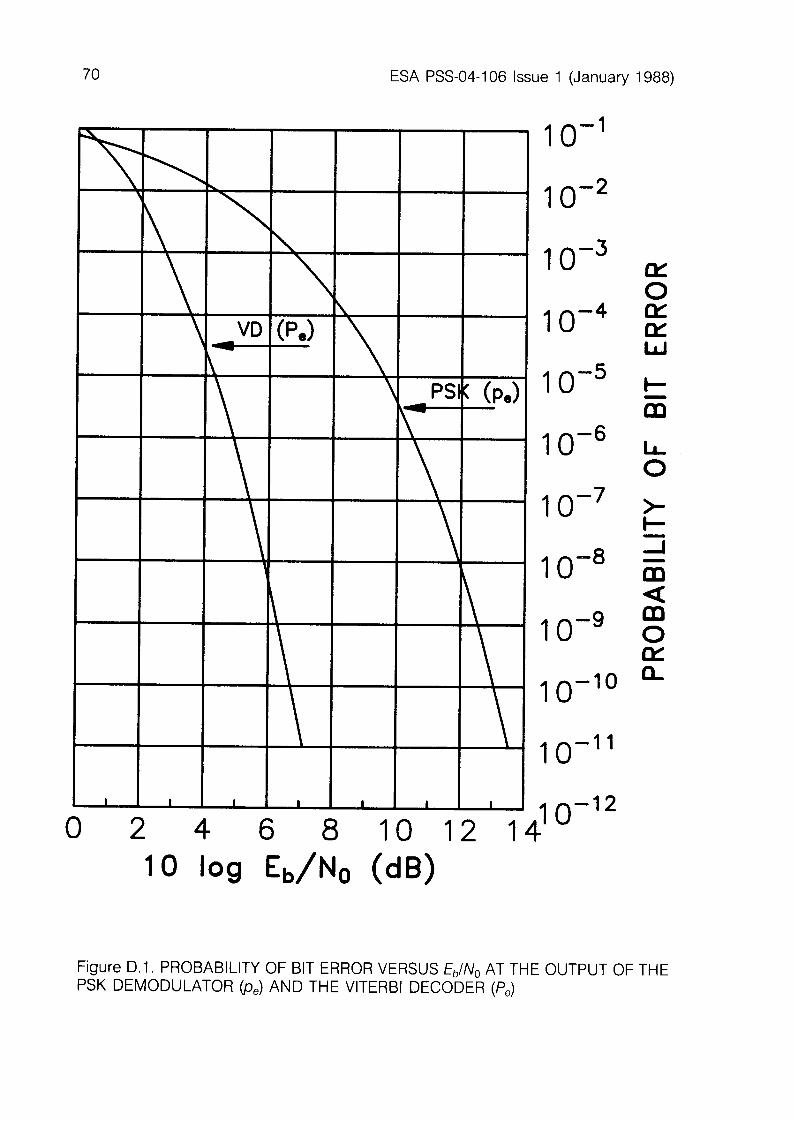
Probability of bit error versus &,/No at the output of the PSK modulator be) and the Viterbi decoder (P,) 70
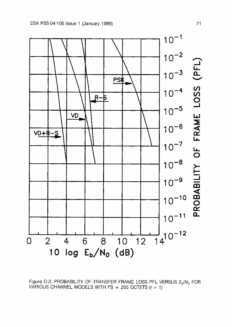
Probability of Transfer Frame loss PFL versus Eb/No for various channel models with FS = 255 octets (I = 1) 71
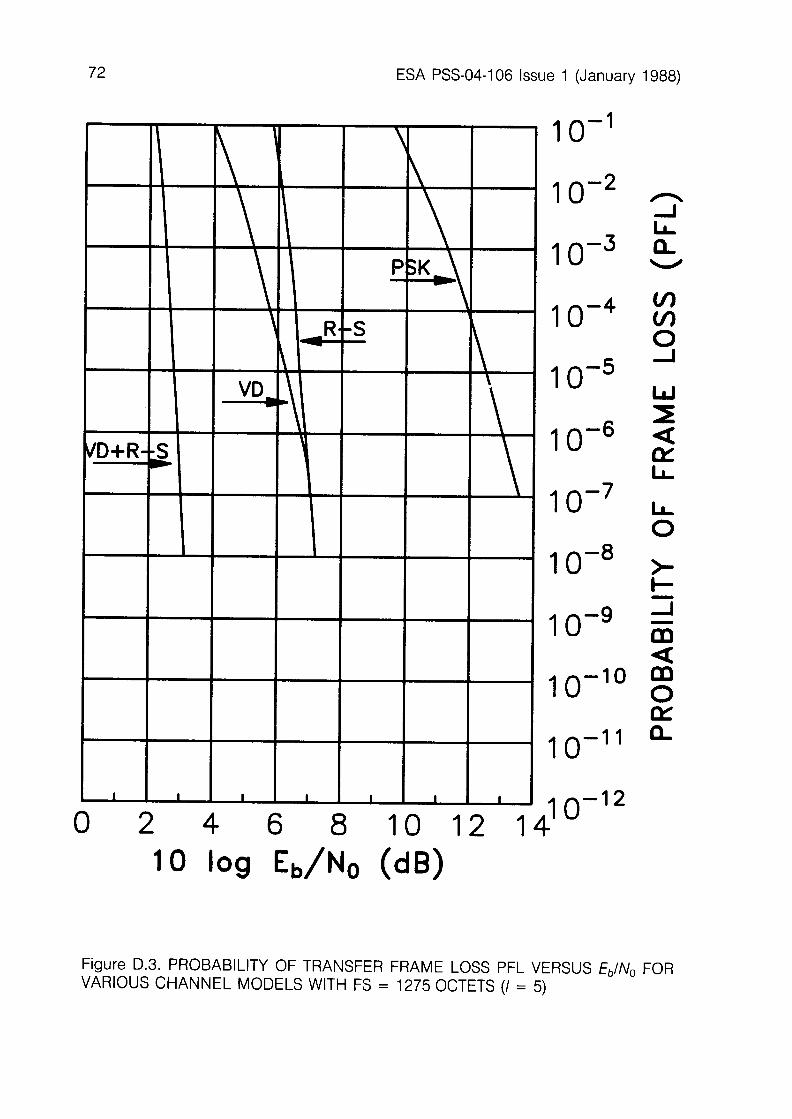
Probability of Transfer Frame loss PFL versus Eb/No for various channel models with FS = 1275 octets (I = 5) 72
Probability of Transfer Frame loss PFL versus &,/No for various channel models with FS = 2040 octets (I = 8) 73
APPENDICES
CORRESPONDENCE WITH CCSDS TERMINOLOGY
SELECTION AND PERFORMANCE OF TRANSFER FRAME SYNCHRONISATION MARKERS
POSSIBLE REALISATION OF A FRAME CHECK SEQUENCE ENCODER-DECODER
PERFORMANCE OF VARIOUS CHANNEL CODING TECHNIQUES
59
61
63
65
ESA PSS-04-106 Issue 1 (January 1988)
PAGE INTENTIONALLY LEFT BLANK
ESA PSS-04-106 Issue 1 (January 1988) 1
1. PURPOSEANDSCOPE
1.1
1.2
PURPOSE
The purpose of this Standard is to establish uniform requirements for the implementation of spacecraft ‘Packet Telemetry’ systems by ESA. To this end the Standard:
establishes a common framework and provides a common basis for the data structures of ESA spacecraft telemetry streams. allows ESA spacecraft projects to proceed coherently with the imple- mentation of spaceborne telemetry systems which are compatible with the ESA ground systems. potentially provides a high level of commonality between both ESA spaceborne and ground-based telemetry systems and the ground systems of other CCSDS Agencies(‘). provides recommendations for the definition of a minimum acceptable level of end-to-end performance for telemetry systems conforming to this Standard.
SCOPE
This Standard belongs to the Space Link Standards & Protocols sub- branch of the ESA PSS branch for Space Data Communications. It supersedes the PCM Telemetry Standard (TTC-A-02).
The Packet Telemetry Standard defines the requirements for packet telemetry protocols and techniques to be used on board ESA spacecraft and at the ESA ground network facilities. Therefore, whenever the standard ESA ground network facilities are to be used, spaceborne telemetry systems shall comply with this Standard. The document is limited to describing the telemetry formats which are generated by the spacecraft in order to execute its role in the two following processes: 0 The end-to-end transport of space mission data sets from source appli-
cation processes located in space to distributed user application pro- cesses located on the ground.
l The intermediate transfer of these data sets through space data- acquisition networks, which contain spacecraft, radio links, tracking sta- tions, ground communications circuits and mission control centres as some of their components.
NOTE (1): CCSDS: Consultative Committee for Space Data Systems. This Standard is directly derived from a technical recommendation on Packet Telemetry issued by the CCSDS (Reference [I]).
ESA PSS-04-106 Issue 1 (January 1988)
The channel coding mechanisms required to implement space-to- ground data links of acceptable quality are defined in Reference [2]. The Packet Telemetry Standard therefore only contains specifications for the following data structures:
(a>
(b)
cc>
A SOURCE PACKET, which is the fundamental user data unit. The Source Packet is used to exchange data between a source application process in space and its associated user application process(es) on the ground. A TELEMETRY PACKET, which is an intermediate protocol data unit. The Telemetry Packet is used to multiplex Source Packets from several source application processes on the same data communications channel. To achieve this, the Telemetry Packet provides a SEGMENTATION mechanism which will enhance intermediate data handling of a given group of sources on board the spacecraft when some of these sources generate very long Source Packets. A TRANSFER FRAME, which is the link protocol data unit. The Transfer Frame is used to transfer the source data through the spacecraft-to- ground communications path. The Transfer Frame also provides a mechanism by which the data link can be time-shared between functionally distinct groups of sources by creating logical VIRTUAL CHANNELS.
ESA PSS-04-106 Issue 1 (January 1988) 3
2. APPLICABILITY
2.1 GENERAL
This Standard applies to all spacecraft sponsored or managed by ESA and using the ESA ground network standard facilities and services.
The capabilities provided within the constraints of this Standard will accommodate the requirements of a great variety of applications for data-handling subsystems, thus providing a universal basis for cost-effective and technically compatible development of data-handling systems in different projects.
2.2 EXCEPTIONS
In exceptional cases, owing to mission-specific requirements, some deviations from this Standard may be warranted. Waivers to any require- ments set forth in this Standard may be obtained only after: l the technical and/or operational advantages of such deviations have
been demonstrated, and/or l it has been shown that the intended change is in line with the existing
systems.
Requests for waivers should be addressed by the Project Manager to the ESA Standards Approval Board (STAB) for Space Data Communications. Such requests should be submitted as early as possible, preferably during the study phase of the project.
4 ESA PSS-04-106 Issue 1 (January 1988)
PAGE INTENTIONALLY LEFT BLANK
ESA PSS-04-106 Issue 1 (January 1988) 5
3. SYSTEM OVERVIEW
3.1 BIT NUMBERING CONVENTION AND NOMENCLATURE
The following CAUTION should be observed when interpreting the bit numbering convention which is used throughout this Standard:
CAUTION
In this document, the following convention is used to identify each bit in a forward-ordered N-bit field.
The first bit in the field to be transmitted (i.e. the most left-justified when drawing a figure) is defined to be ‘Bit 0’; the following bit is called ‘Bit 1’ and so on up to ‘Bit N-l ‘. When the field is used to express a binary value (such as a counter), the Most Significant Bit (MSB) shall be the first transmitted bit of the field, (i.e., ‘Bit 0’).
Bit 0 Bit N-l
\! Y
N-BIT DATA FIELD
I+ First bit transmitted = MSB
Spacecraft data fields are often grouped into 8-bit ‘words’ which conform to the above convention. In accordance with modern data- communication practice, the following nomenclature is used throughout this Standard to describe this grouping:
OCTET = 8-bit word
In this document, the above-defined numbering convention for identifying a bit is also used for identifying each octet in a forward-ordered N-octet field.
6
3.2
ESA PSS-04-106 Issue 1 (January 1988)
TELEMETRY DATA FLOW
Figure 3.1 is a functional diagram of the telemetry data flow from the creation of a data set by an application process operating within a spacecraft ‘source’ (instrument or subsystem) through to the delivery of the same data set to a user ‘sink’ (application process) on the ground. The Packet Telemetry concept permits the definition of stable mission-independent interface standards for the communications paths within the flow.
Data structures within a packet telemetry system are provided for the following purposes:
(a>
03
cc>
To-ail& the user to optimise the size and structure of his application data set with a minimum of constraints imposed by the spacecraft-to- ground communications system. The user should thus be able to define his data organisation independently of other users and to adapt this organisation to the various modes of his data source.
The data structure which makes this independence possible is the Source Packet. User data are encapsulated within a packet by prefacing them with a standard label or ‘Packet Header’, which is used by the data transfer system for packet handling and identification. To allow the ground data-acquisition system to capture the packets in a standardised way, with a data-independent method of performing packet reassembly and determination of data quality. The data structure within the packet telemetry system for achieving this is the Transfer Frame, which provides the necessary header elements for extracting packets or segments from the frame and features error-detection coding for deciding whether the frame handling process has been error free. To allow the spacecraft terminus of the data-transfer system to be designed and tested without a detailed definition of all user data organisations.
Since most space communications systems are capacity-limited, multiple users must be guaranteed access to the downlink data channel. It is therefore important for the spacecraft to be able to manage the data flow to the ground in an orderly manner. To this end, two mechanisms are provided, namely: 0 Segmentation: the Telemetry Packet”’ structure permits breaking
long Source Packets into shorter pieces to enable interleaving of the various data from a given group of sources. This permits a better control of the total source data flow.
NOTE (1): For more information on this ESA term see Appendix A: Correspondence with CCSDS Terminology.
ESA PSS-04-106 Issue 1 (January 1988) 7
a Virtual Channelisation: the Transfer Frame structure permits groups of sources of very different characteristics to be separated by assigning each group to a dedicated sequence of Transfer Frames: the Virtual Channel. The frames of each Virtual Channel are interleaved in accordance with the frequency requirements of each Virtual Channel.
Section 4 describes the Source Packet and Telemetry Packet structures. Section 5 describes the Transfer Frame. Section 6 describes the standard mechanisms (protocols) offered by these structures during the end- to-end transmission process. Section 7 covers the standard protocols related to the acquisition of spacecraft time and its correlation with ground time.
a ESA PSS-04-106 Issue 1 (January 1988)
APPLICATION DATA:
SOURCE PACKETS:
r-7 a@
f-l OURCE-A
+
apl ap2 ap3 SQ SOURCE-B
+
TELEMETRY PACKETS:
VIRTUAL CHANNELS:
TRANSFER FRAMES:
SEGMENT SOURCE PACKETS, IF REQUIRED
t
INSERT TELEMETRY PACKETS INTO FRAMES OF
APPROPRIATE VIRTUAL CHANNELS
MULTIPLEX THE FRAMES OF DIFFERENT VIRTUAL
CHANNELS INTO ONE SEQUENCE OF FRAMES
CREATE PHYSICAL DATA CHANNEL
TERMINATE PHYSICAL DATA CHANNEL
DEMULTIPLEX THE FRAMES OF DIFFERENT
VIRTUAL CHANNELS
EXTRACT TELEMETRY PACKETS FROM APPROPRIATE
VIRTUAL CHANNELS
t
RECONSTRUCT SOURCE PACKETS FROM SEGMENTS,
IF REQUIRED
t t
Figure 3.1 TELEMETRY DATA FLOW
ESA PSS-04-106 Issue 1 (January 1988) 9
4. PACKET FORMATS
4.1 GENERAL
This section defines two protocol data units: a the protocol data unit which must be presented by the spaceborne data
source to the data transfer system for transmission to the ground: this unit is the SOURCE PACKET.
l the protocol data unit which is used by the data transfer system to carry out its transport task effectively: this unit is the TELEMETRY PACKET.
(a) Source Packet
The Source Packet must, in addition to the source data, carry a minimum of information needed by the ground data capture system for the acquisition, storage and distribution of the source data to the end user. Thus, the Source Packet format consists of two major fields: l The Packet Header, of fixed length, which provides the standardised
control information required during the end-to-end transport process from the source on board the spacecraft to the end-user data- processing equipment on the ground.
0 The Packet Data Field, of variable length, which contains the source data.
The standardised control information that the Source Packet Header must provide is the following: a Identification of the source and its application process: for data
distribution, storage and retrieval. l Sequence numbering for a given source and its application process: for
sequence tracking and accounting. 0 Packet Data Field length: information used throughout the transport
process.
The only other constraint placed on the data source is that the length of the Packet Data Field must not exceed 216 (65536) octets.
The Source Packet format is specified in Section 4.2.
(b) Telemetry Packet
Telemetry Packets are used to multiplex Source Packets onto the telemetry data channel. To avoid the ‘capture’ of the data channel by long Source Packets at the expense of the shorter ones, all Source Packets with a Data Field exceeding a prescribed length (designated LSEGMENT) are
IO ESA PSS-04-106 Issue 1 (January 1988)
‘segmented’ into several shorter Telemetry Packets. Given a Source Packet with a Data Field length L, the procedure is as follows:
L = (m x LSEGMENT) + R
where: m L
= integer, from 0 to 255 max. = Source Packet Data Field length, in octets
(from 1 to 65 536 max.). LSEGMENT = maximum Telemetry Packet Data Field length,
in octets (fixed parameter for each Virtual Channel, with a maximum of 65 536).
R = Source Packet Data Field residue, in octets (0 < R 5 LSEGMENT).
This Source Packet will be transferred to ground as a sequence of ‘m’ Telemetry Packets with a Data Field length of LSEGMENT ending with a Telemetry Packet with a Data Field length of R. These Telemetry Packets, although transmitted in logical order, need not be contiguous as they can be separated by interleaving Telemetry Packets from other sources. When L 5 LSEGMENT, then L= R and only one Telemetry Packet is generated. In such a case, the commonality between the Source and Telemetry Packet Headers is such that the Source Packet passes through the segmentation process unchanged. Ultimately, if so desired by the mission (because of network compatibility, for instance), it is possible to allow all Source Packets to be transferred unchanged by selecting the maximum value of LSEGMENT (65 536).
Therefore, the Telemetry Packet consists of two major fields: 0 the Packet Header, of fixed length, which must provide the same
information contained in the Source Packet Header plus enough control information to reconstruct the Source Packet.
l the Packet Data Field, of variable length which contains the various segments (of length LSEGMENT or R) of the original Source Packet Data Field.
The additional control information that the Telemetry Packet Header must provide is: l Identification of Telemetry Packet segmentation sequence. 0 Identification of Data Field length R (LSEGMENT is identified at the
Transfer Frame level - see Section 5).
The Telemetry Packet format is specified in Section 4.3. The Source Packet Segmentation process is described in Subsection 6.4.1 and is illustrated in Figure 6.1.
ESA PSS-04-106 Issue 1 (January 1988) 11
PACKET HEADER PACKET DATA FIELD
(48) (VARIABLE)
Version Number
3
PACKET IDENTIFICATION
TYPE
1
Data Field Header Flag
1 14 16 16 16
Appli- cation Process ID
11
PACKET SEQUENCE CONTROL
PACKET LENGTH
Segment- ation Flags
2
Source Sequence Count
DATA FIELD SOURCE PACKET HEADER DATA ERROR
(OPTIONAL) CONTROL (OPTIONAL
May contain:
l S/C Time * Packet
Format
Figure 4.1 SOURCE PACKET FORMAT.
4.2 SOURCEPACKETFORMAT
The Source Packet Format, which is shown in Figure 4.1, consists of two major fields: l the Packet Header, with a fixed length of 48 bits (6 octets). l the Packet Data Field, with a variable length from 1 to 65 536 (216)
octets.
4.2.1 Source Packet Header
The Packet Header shall consist of 48 bits subdivided into the following fields:
FIELD LENGTH (BITS)
PACKET IDENTIFICATION - Version Number (3)
- Type (1) - Data Field Header Flag (1) - Application Process ID (11) PACKET SEQUENCE CONTROL - Segmentation Flags (2) - Source Sequence Count (14) PACKET LENGTH
16
16
16
48
12 ESA PSS-04-106 Issue 1 (January 1988)
4.2.1 .l Packet Identification (16 Bits)
Packet Identification is a 16-bit field divided into four subfields namely Version Number (3 bits), Reserved Bit (1 bit), Data Field Header Flag (1 bit) and Application Process Identifier (11 bits).
(a) Version Number (Bits 0 through 2)
The Version Number is a 3-bit field occupying the three most significant bits of a packet structure. The Version Numbers are defined by the CCSDS. IN THIS STANDARD, ONLY ONE VERSION NUMBER (VERSION 2) IS PERMITTED, and this specifies the packet formats described in this Section. This number is:
(b) Type (Bit 3)
l Bits 0 through 2 = 100
Packets may be identified to be either telemetry type (Bit 3=0) or telecommand type (Bit 3 = 1). All telemetry Source Packets shall have this bit set to ‘0’.
(c) Data Field Header Flag (Bit 4)
The Data Field Header Flag indicates the presence (Bit 4= 1) or absence (Bit 4= 0) of a Data Field Header within the Packet Data Field.
(d) Application Process Identifier (Bits 5 through 15)
The Application Process Identifier is an 11 -bit field uniquely identifying both the physical source (instrument or subsystem unit) and the particular application process within this physical source which created the Source Packet. A physical source may ‘own’ more than one application process. Any Identifier is unique on board a given spacecraft, regardless of the number of Virtual Channels used(‘).
The Application Process Identifiers are tailored to the mission needs, in general, and to the overall data handling system requirements, in particular. They are ultimately assigned by the Mission Control authority. Each Application Process Identifier is logically associated with the Source Sequence Count subfield of the Packet Sequence Control field. This is to allow the ground telemetry acquisition systems to control the continuity of packet delivery for each Application Process ID (see Subsection 4.2.1.2).
NOTE (1): The space vehicle itself is identified by the Spacecraft Identifier in the Transfer Frame Header, as described in Section 5.
ESA PSS-04-106 Issue 1 (January 1988) 13
Reserved Identifiers
a The ‘all ones’ configuration of the Application Process ID shall be reserved to identify ‘Idle Source Packets’ which are generated by the spacecraft data transport system to maintain synchronisation of the packet extraction process on ground during periods when no sources have packetised data available for transfer to the ground.
0 The ‘all zeros’ configuration of the Application Process ID shall be reserved to identify the standard Source Packet containing the Spacecraft Time sample (see Section 7).
4.2.1.2 Packet Sequence Control (16 Bits)
Packet Sequence Control is a 16-bit field which is subdivided into two separate fields, namely Segmentation Flags (2 bits) and Source Sequence Count (14 bits).
(a) Segmentation Flags (Bits 0, 1)
The Segmentation Flags occupy the two most-significant bits of the 16-bit field. In the Source Packet, the Segmentation Flags shall always be set to ‘all ones’. The other states of the Segmentation Flags are covered in Section 4.3.
(b) Source Sequence Count (Bits 2 through 15)
This 14-bit field contains a straight sequential count (modulo 16 384) of each packet generated by each unique source application process (as specified by the Application Process ID) on the spacecraft. The field will allow the ground telemetry acquisition systems to control the continuity of packet delivery for each Application Process ID.
During the continuous operation of a source application process, it is not permissible for the source to ‘short cycle’ the sequence counter by resetting before the full counter accumulation has been reached; however, if the operation of a source is interrupted (e.g. through the power supply’s being switched off), the source may start a new sequence count when its operation is resumed.
The source application process responsible for generating the Idle Source Packets (Application Process ID ‘all ones’) is not required to maintain a Source Sequence Count.
14 ESA PSS-04-106 Issue 1 (January 1988)
4.2.1.3 Packet Length (16 Bits)
The Packet Length is a 16-bit field which specifies the number of octets contained within the Packet Data Field. The number is a binary value ‘C’ expressed as follows:
C = [(Number of octets in Data Field) - I]
Therefore, it should be noted that the actual length of the entire Source Packet will implicitly be 6 octets longer, since the standard 48-bit Packet Header always precedes the Packet Data Field. Also, the smallest possible Source Packet length is 7 octets and the largest possible is 65 542 octets.
The length of an Idle Source Packet is defined in Subsection 4.3.3.
4.2.2 Packet Data Field
4.2.2.1 General
The Packet Data Field contains the information which is specific to the generating source on board the spacecraft. The only formal restriction imposed on this field is that its total length must be an integral number of octets; for the rest, the user will normally have complete freedom to specify the data content and the internal format of this field. However, users are cautioned that if the packet contents are to be processed within CCSDS agency support facilities, then local standards for internal formatting may be imposed. As an introduction to such standards, an optional subdivision of the Packet Data Field has been established, which is defined briefly in the following subsections. The detailed specification of such data structures and their protocols is not the subject of this Standard(‘).
The subfields of the Packet Data Fieldc2) are: l Data Field Header(*) (optional and variable) 0 Source Data (variable) 0 Packet Error Control (optional and variable).
NOTE (1): The user is cautioned that the standard network facilities do not provide services associated with the Packet Data Field. The only exception concerns the Spacecraft Time Source Packet and the related time correlation services (see Section 7).
NOTE (2): For more information on these ESA terms, see Appendix A: Correspondence with CCSDS Terminology.
ESA PSS-04-I 06 Issue 1 (January 1988) 15
4.2.2.2 Data Field Header
The Data Field Header is an optional subdivision of the Packet Data Field.
The purpose of the Data Field Header is to provide a standard means for inserting within the first octets of a Source Packet Data Field any ancillary data (time, additional packet type identification, internal data field format identification, etc.) which may be necessary to permit the interpretation of the source data contained within the packet by common data-processing facilities.
The presence or absence of a Data Field Header must be signalled by the Data Field Header Flag in the Packet Header.
The length of the Data Field Header shall be a multiple (integer) of octets. Comprehensive standards for the format of the Data Field Header are not the subject of this Standard.
4.2.2.3 Source Data
The Source Data field is a subdivision of the Packet Data Field. It is the user data in the form of a sequence of octets.
4.2.2.4 Packet Error Control
The Packet Error Control field is an optional subdivision of the Packet Data Field.
The standard mechanisms that are used by the ground telemetry acquisition systems to extract Telemetry Packets from the Transfer Frame are such that no use is made of a Packet Error Control field (Telemetry Packets do not have such a field in any case). However, at the discretion of the user, an optional error detection code may be appended to the Source Data Field so that the ultimate recipient of the data is able to verify that the integrity of the complete Source Packet structure has been preserved during the entire transport process. The length of the Packet Error Control field shall be a multiple (integer) of octets. The coding and the format of the Packet Error Control field are not the subject of this Standard.
4.3 TELEMETRY PACKET FORMAT
The Telemetry Packet format, which is shown in Figure 4.2, consists of two major fields: a the Packet Header, with a fixed length of 48 bits (6 octets); 0 the Packet Data Field, with a variable length from 1 to LSEGMENT
octets.
16 ESA PSS-04-106 Issue 1 (January 1988)
PACKET HEADER PACKET DATA FIELD
(46) (VARIABLE)
PACKET IDENTIFICATION T
Version Type Data Appli- Number Field cation
Header Process Flag ID
3 1 1 11
I 16 16 I
16
Segment- ation Flags
2
Original Source Packet Source Sequence Count
ld
SEGMENTED SOURCE PACKET DATA
FIELD
256, 512, 1024 OF,, 65536 octets max.
Figure 4.2 TELEMETRY PACKET FORMAT.
4.3.1 Telemetry Packet Header
The structure of the Telemetry Packet Header is identical to that of the Source Packet Header. Its component fields are strictly a repeat of the corresponding Source Packet Header fields, except for the Segmentation Flags and the Packet Length, which are specified in the following subsections.
4.3.1 .l Segmentation Flags (2 Bits)
When a Source Packet is converted into one, two, or more Telemetry Packets, the Segmentation Flags will be set as follows:
Bit 0 Bit 1
0 1 0 0 1 0 1 1
Interpretation
First segment Continuation segment Last segment Unsegmented
When the Source Packet is left unchanged, therefore, the Segmentation Flags remain set at ‘11’ (as specified in Subsection 4.2.1.2) and this means that the Telemetry Packet is, in fact, an unsegmented Source Packet.
NOTE (1): See Subsection 54.4, Para. (d)
ESA PSS-04-106 Issue 1 (January 1988) 17
4.3.1.2 Packet Length (16 Bits)
In general, the Packet Length field of both Source Packet and Telemetry Packet structures indicates the same information, that is, the length of the original Source Packet Data Field which remains to be transmitted. For a Source Packet, it indicates the length of the complete Source Packet Data Field. For a Telemetry Packet it indicates the length of the complete Source Packet Data Field, minus (m x LSEGMENT).
(a)
( w
(c)
(d)
In summary: Unsegmented Packet (Segmentation Flags = 11): the length field indicates the length of both Source and Telemetry Packet Data Fields. First Segment of a Segmented Packet (01): the length field indicates the length of the original Source Packet Data Field.The length of the Telemetry Packet Data Field itself is shorter and is equal to LSEGMENT. Continuation Segment (m) of a Segmented Packet (00): the length field indicates the length of the original Source Packet Data Field decremented by (m x LSEGMENT), where m = 1, 2, 3, etc., according to the sequential number of the continuation segment. The length of the Telemetry Packet Data Field itself is equal to LSEGMENT, as for the first segment. Last Segment of a Segmented Packet (10): the length field indicates a value which must be less than or equal to LSEGMENT. The length of the Telemetry Packet Data Field itself is equal to the indicated value, since the field contains the residue of the original Source Packet Data Field.
Note that the convention of:
Indicated length = [(Number of octets) - l]
is used for the Packet Length as defined in Subsection 4.2.1.3.
4.3.2 Telemetry Packet Data Field
The Telemetry Packet Data Field contains all or a segment of the original Source Packet Data Field, as described in the previous subsections.
The restriction imposed on this field is that its total length shall be an integral number of octets not exceeding the parameter value LSEGMENT prescribed for the given Virtual Channel, and conforming to the segmentation rules given in Section 4.1.
18 ESA PSS-04-106 issue 1 (January 1988)
4.3.3 Idle Telemetry Packets
Idle Source Packets [defined in Paragraph 4.2.1.1(d)] shall have a Packet Data Field length not exceeding LSEGMENT. Thus, an Idle Telemetry Packet shall always be identical to an Idle Source Packet.
ESA PSS-04-106 Issue 1 (January 1988) 19
5. TRANSFER FRAME FORMAT
5.1 GENERAL
The Transfer Frame is the protocol data unit in which Telemetry Packets (as described in Section 4) are embedded for transmission through the downlink data channel.
The Transfer Frame uses lower-layer services (e.g. RF carrier, modulation and coding) in order to establish the downlink data path. The quality of these services depends upon many factors, including the received signal-to-noise ratio and the coding scheme used, if coding is ap lied to the data channel in order to improve the system error performance(’ P
. Although Packet Telemetry systems may be designed to tolerate channel noise in the same way as conventional systems have been designed in the past (i.e., by placing data within the frame in a predetermined sequence), full benefits -
such as automated extraction of Telemetry Packets - will require a high- quality data channel to be provided. Performance requirements and related telemetry services are defined accordingly in Section 9.
The general format of the Transfer Frame is shown in Figure 5.1. It consists essentially of four fields: 0 the Transfer Frame Primary Header 0 the Transfer Frame Secondary Header 0 the Transfer Frame Data Field l the Transfer Frame Trailer
(a) Transfer Frame Primary Header
The Transfer Frame Primary Header provides services which are common to all missions. These services are principally:
(0
(ii) (iii)
(iv)
Detection of missing frames in the single physical data channel (Master Channel Frame Count) and confirmation of correct frame synchronisation. Identification of spacecraft (S/C ID). Identification of each sequence of frames corresponding to a Virtual Channel, with detection of missing frames (VC ID + VC Frame Count). Provision of pointers and other control information so that the variable- length Telemetry Packets may be extracted from the fixed-length Frame Data Field (Frame Data Field Status).
NOTE (1): Telemetry channel coding is the subject of Reference [2].
20 ESA PSS-04-106 Issue 1 (January 1988)
(b) Transfer Frame Secondary Header
The Transfer Frame Secondary Header is optional. In this Standard, it is used to expand the Virtual Channel Frame Count field whenever this is required by a particular mission. Typically, this type of service must be considered when Transfer Frames are recorded on board the spacecraft and played back later through a real-time Virtual Channel.
(c) Transfer Frame Data Field
The Transfer Frame Data Field contains the user application data (normally: Telemetry Packets) to be transferred from the spacecraft to the ground.
(d) Transfer Frame Trailer
The Transfer Frame Trailer provides optional services which are relevant to the quality of the data channels established between the ground and the spacecraft: (i) Telemet ry downlink: Detection of errors which may have occurred
within the frame. (ii) Telecom mand uplink: Standard real-time reporting of telecommand
data link error detection on board the spacecraft, for the purpose of implementing automated retransmission operations.
5.2 TRANSFER FRAME LENGTH
5.2.1 General Specification
Within a single physical downlink channel of a particular mission, the total length of the Transfer Frame shall be a fixed number (integer) of octets; the implemented length shall be specified to the ground network as a mission set-up parameter. A maximum length of 1784 octets has been computed for the case where the Transfer Frame is synchronously inserted into a standard Reed-Solomon codeblock structure with an interleaving depth of eight. Figure 5.1 illustrates how a Transfer Frame is synchronously embedded in the standard Reed-Solomon codeblock. In Figure 5.1, the Transfer Frame length is 1115 octets (8920 bits), which is the standard length for cross- support between CCSDS agencies. It corresponds to a standard Reed- Solomon codeblock structure with an interleaving depth of five, as specified in Reference [2].
ESA PSS-04-106 Issue 1 (January 1988) 21
TRANSFER FRAME (8920 bits)
ATTACHED SYNC.
MARKER
TRANSFER FRAME
HEADER
PRI. SEC.
(Opt.)
TRANSFER FRAME DATA FIELD
TRANSFER FRAME
TRAILER
(Opt.)
32 48 0, 32 Variable 0, 16, 32 or 48
ATTACHED SYNC. REED-SOLOMON DATA SPACE
REED-SOLOMON
MARKER CHECK SYMBOLS
I I I
32 8920 I 1280
REED-SOLOMON CODEBLOCK (10,200 bits)
Figure 5. I COMPOSITE TRANSFER FRAME/REED-SOLOMON CODEBLOCK FORMAT
The major fields of the upper composite data structure shown in Figure 5.1. are as follows:
MAJOR FIELD LENGTH (BITS)
Attached Synchronisation Marker Transfer Frame Primary Header Transfer Frame Secondary Header (optional) Transfer Frame Data Field Transfer Frame Trailer (optional)
32 48 0 or 32 Variable 0,16,32 or 48
Total Length Up to 8952
22 ESA PSS-04-106 Issue 1 (January 1988)
5.2.2 Transfer Frame Lengths
This Standard allows the following frame lengths:
(a) When using Reed-Solomon coding:
0 CCSDS standard frame length: - 1115 octets This is the CCSDS standard for cross-support. The interleaving depth is I = 5, for a total R-S codeblock length R-S = 1275 octets.
l Other standard frame lengths: - 892 octets, with I = 4 and R-S = 1020 octets;
- 1784 octets, with I = 8 and R-S = 2040 octets.
Shorter lengths may be obtained through the use of the ‘virtual fill’ option [Ref. 21.
(b) When Reed-Solomon coding is not used:
l Minimum frame length: - 128 octets 0 Maximum frame length: - 2040 octets l Other frame lengths: - Any length, between the above
specified limits, which is a multiple (integer) of octets.
Warning: Ground equipment characteristics may impose limitations on the maximum frame rate (see also Section 8).
5.3 ATTACHED SYNCHRONISATION MARKER
The Attached Synchronisation Marker delimits the boundaries of a fixed-length Transfer Frame. If the frame is not Reed-Solomon encoded, it is used by ground equipment to acquire synchronisation with the frame boundaries after transmission through the data channel. If the frame is Reed- Solomon encoded, the marker serves to synchronise the Reed-Solomon codeblock. Rules for these two cases of attaching the synchronisation marker to the Transfer Frame or to the Reed-Solomon codeblock are described in Sections 5.3.1 and 5.3.2.
Care should be taken that this synchronisation marker (or its reversed and/or complemented pattern) does not routinely appear in any other portion of the Transfer Frame. This does not preclude the occasional random presence of this pattern elsewhere in the frame. Section 5.3.3 proposes a second synchronisation marker pattern for critical cases.
ESA PSS-04-106 Issue 1 (January 1988) 23
5.3.1 Synchronisation Marker without Reed-Solomon Coding
When Reed-Solomon coding is not used as part of the overall channel code, all Transfer Frames shall have a 32-bit synchronisation marker attached to and immediately preceding the Transfer Frame shown in Figure 5.1. The 32-bit synchronisation marker patter1 -l follows:
Header, as shall be as
L 0001 1010 1100 1111 1111 1100 0001 1101
FIRST TRANSMITTED LAST TRANSMITED- BIT (Bit 0) BIT (Bit 31)
This pattern may be represented in hexadecimal notation as:
1ACFFClD
This pattern was chosen to provide good synchronisation properties with a low false alarm probability in a noisy channe! under the following conditions: true as well as complemented data sense, forward as well as reverse time ordering, and synchronisation directly in the bit domain as well as in the symbol domain (as translated by the recommended convolutional code of Reference [2]).
5.3.2 Synchronisation Marker with Reed-Solomon Coding
When Reed-Solomon coding is used as part of the overall channel code, and each Transfer Frame is synchronously imbedded within a Reed- Solomon codeblock, the codeblock shall have an Attached Synchronisation Marker immediately preceding it, as described in Reference [2]. It should be noted that this marker is not part of the codeblock’s 8920-bit data space, and that the imbedded Transfer Frame should not include its own marker. The bit pattern for the Attached Synchronisation Marker of the codeblock shall normally be identical to that specified for the Transfer Frame alone (Section 5.3.1) unless otherwise stipulated by Reference [2].
5.3.3 Second Synchronisation Marker Pattern
A second synchronisation marker pattern may be required for those cases where another telemetry data stream (e.g., a stream of Transfer Frames played back from a tape recorder in the forward mode instead of the reverse mode, thus interfering with the real-time Transfer Frame synchronisation process on ground) is inserted into the data field of real-time
24 ESA PSS-04-106 Issue 1 (January 1988)
Transfer Frames. For such cases, the following 32-bit synchronisation pattern may be used as the second (imbedded) Attached Synchronisation Marker:
hexadecimal: 3 5 2 E F 8 5 3
The selection criteria and performance analysis justifying the choice of these two synchronisation markers are briefly presented in Appendix B: Selection and Performance of Transfer Frame Synchronisation Markers.
5.4 TRANSFER FRAME PRIMARY HEADER
The Transfer Frame Primary Header, which is shown in Figure 5.2, is composed of the following fields:
MAJOR FIELD LENGTH (BITS)
FRAME IDENTIFICATION - ‘Version Number (2) - Spacecraft ID (10) - Viriual Channel ID (3) - Operational Control Field Flag (1) MASTER FRAME COUNT VIRTUAL CHANNEL FRAME COUNT FRAME DATA FIELD STATUS - Secondary Header Flag (1) - Synchronisation Flag (1) - Packet Order Flag (1) - Segment Length ID (2) - First Header Pointer (11)
16
8 8
16
48
5.4.1 Frame Identification (16 Bits)
The purpose of the Frame Identification field is to identify which operational spacecraft created the frame of data and to indicate whether the physical data link is logically switched to form ‘Virtual Channels’. The field is broken into four subfields, namely Version Number (2 bits), Spacecraft identifier (10 bits), Virtual Channel Identifier (3 bits), and Operational Control Field Flag (1 bit).
ESA PSS-04-106 Issue 1 (January 1988) 25
TRANSFER FRAME PRIMARY HEADER
SYNC vlARKER
32
FRAME
IDENTIFICATION
~ I ID
2 10 3
16
Operat Control Field Flag
1
MASTER
CHANNEL
FRAME COUNT
VIRTUAL
CHANNEL
FRAME
COUNT
FRAME
DATA FIELD
STATUS
Sec. Hea- der Flag
1
8 8 16
Seg- ment Length ID
2
First
Header Pointer
11
Figure 5.2 TRANSFER FRAME PRIMARY HEADER FORMAT.
(a) Version Number (Bits 0, 1)
These two bits (which occupy the two most significant bits of the 16-bit field) are reserved by the CCSDS for potential evolution of the Transfer Frame structure. IN THIS STANDARD, ONLY ONE VERSION NUMBER (VERSION 1) IS RECOGNIZED, which specifies the Transfer Frame structure described herein. This number is:
/ l Bits 0,l = 00 1
(b) Spacecraft Identifier (Bits 2 through 11)
This IO-bit field provides positive identification of: l the spacecraft itself l the particular physical link used to transmit the Transfer Frames from the
spacecraft to the ground.
Therefore, a single spacecraft may require as many identifiers as it has physical links. Also, separate spacecraft identifiers should be assigned for flight vehicles, for development vehicles which are using the ground networks during prelaunch test operations, and for simulated data streams.
ESA Projects shall obtain these identifiers from the ESA Directorate of Operations (D/OPS), ESOC, Darmstadt, FRG.
26 ESA PSS-04-106 Issue 1 (January 1988)
(c) Virtual Channel Identifier (Bits 12, 13, 14)
This 3-bit field enables up to eight Virtual Channels to be run concurrently by a particular spacecraft on a particular physical data channel. When only one Virtual Channel is foreseen to be on the physical data channel, the number of the Virtual Channel shall be ‘0’. When more than one Virtual Channel exists, Channel ‘0’ shall always be transmitted whenever spacecraft time correlation is required (see Section 7).
Channel ‘0’ is coded ‘000’, Channel ‘1’ is coded ‘001’) and so forth, the last channel (‘7’) being coded ‘Ill’.
(d) Operational Control Field Flag (Bit 15)
This l-bit field is used to signal the presence (Bit 15= 1) or absence (Bit 15 = 0) of the 32-bit Operational Control Field within the Transfer Frame Trailer. This field contains the telecommand verification report called ‘Command Link Control Word’ (see Section 5.6). If implemented, the Operational Control Field shall appear in every frame transmitted through a physical data channel.
5.4.2 Master Channel Frame Count (8 Bits)
The purpose of the Master Channel Frame Count field is to provide an 8-bit sequential up-count (modulo 256) of each Transfer Frame generated by the spacecraft on a given physical data channel (the Master Channel). The least-significant bit of the field is Bit 7. The counter must be left free-running, i.e. it shall not be short-cycled.
5.4.3 Virtual Channel Frame Count (8 Bits)
The purpose of the Virtual Channel Frame Count field is to provide individual accountability for each of the Virtual Channels. The 8-bit field represents a sequential up-count (modulo 256) of the frames assigned to each of the Virtual Channels. It is used in association with the Virtual Channel ID field to maintain a separate counter for each of up to eight separate Virtual Channels. The least-significant bit of the field is Bit 7. The counter must be left free-running, i.e. it shall not be short-cycled.
5.4.4 Frame Data Field Status (16 Bits)
The purpose of the Frame Data Field Status field is to provide control information to enable Telemetry Packets to be extracted from the frame data field. The field is broken into five subfields,namely Secondary Header Flag (1 bit), Data Field Synchronisation Flag (1 bit), Packet Order Flag (1 bit), Segment Length Identifier (2 bits) and First Header Pointer (11 bits).
ESA PSS-04-106 Issue 1 (January 1988) 27
(a) Secondary Header Flag (Bit 0)
This 1 -bit field is used to indicate the presence (Bit 0 = ‘1’) or absence (Bit 0= ‘0’) of the optional Secondary Header in the Transfer Frame. If present, the Secondary Header shall immediately follow the Primary Header, and the beginning of the Transfer Frame Data Field shall be correspondingly shifted.
If implemented, the Secondary Header shall appear in every frame transmitted through a physical data channel (Master Channel). Also, the length of the Secondary Header must be fixed within that physical channel (see Section 5.5).
(b) Data Field Synchronisation Flag (Bit 1)
The synchronisation status of the data which are inserted into the Transfer Frame Data Field shall be indicated by setting the Data Field Synchronisation Flag (Bit 1) as follows:
Bit 1 = 0: standard packets are synchronously inserted. Bit 1 = 1: standard packets are asynchronously inserted, or the data are
not standard packets.
The normal mode of inserting the octets making up the packets into the Transfer Frame Data Field shall be to place them synchronously on the frame octet boundaries, one after the other. Packets will be permitted to ‘spill over’ into the next frame of the same Virtual Channel. The location of the first packet header in a particular frame will be specified by the First Header Pointer field.
Therefore, when the Data Field Synchronisation Flag is set to a ‘O’, it indicates synchronous insertion of standard packets. Any other insertion mode shall be flagged as asynchronous (Bit 1 = 1). This applies to: l Standard packets which are inserted asynchronously within the frame
data field (the frame octet boundaries do not coincide with the packet octet boundaries).
l Any type of source data other than the standard packets, which are inserted within the frame data field, whether asynchronously or not.
When the flag is set to ‘I’, the remaining frame data field status information shall be ignored, and it shall normally be a project responsibility to extract information from the frame data field.
An exception to this exists which concerns a standard provision made for the extraction of asynchronously inserted Transfer Frames. Typically, this situation occurs when Transfer Frames have been stored in an on-board memory device (e.g., a tape recorder), to be dumped later into a real-time frame data field, asynchronously, either in the forward or the reverse mode.
28 ESA PSS-04-106 Issue 1 (January 1988)
Section 6 (Telemetry Transmission Protocols) covers this standard provision for playback data.
(c) Packet Order Flag (Bit 2)
During real-time transmission of information from spacecraft sources to the ground on a given Virtual Channel, the order of the Telemetry Packets inserted within the frame data field as they appear to the ground processor will be ‘forward’ justified (i.e., they will appear with their most significant bit transmitted first, and with their sequence counters incrementing in an increasing order). The Packet Order Flag has been provided by the CCSDS to indicate certain conditions where the order of the Packet Sequence Control information (Segmentation Flags, Source Sequence Count) within the packet may be reversed.
(i) Synchronous insertion of packets
The order in which the Telemetry Packets are synchronously inserted (Bit 1 =0) within the frame data field is indicated by setting the Packet Order Flag (Bit 2) as follows:
Bit 2 = 0: Packet sequence count/segmentation order is forward. Bit 2 = 1: Packet sequence count/segmentation order is reverse.
IN THIS STANDARD, ONLY THE FORWARD ORDER OF SYNCHRONOUS INSERTION OF PACKETS IS RECOGNIZED. THEREFORE, BIT 2 SHALL ALWAYS BE SET TO ‘0’ WHEN BIT 1 0. =
(ii) Asynchronous insertion of data
When Bit 1 = 1 (asynchronously inserted data), Bit 2 is normally not used by the network and shall be set to ‘0’ unless otherwise agreed between a particular mission project and the network.
(d) Segment Length Identifier (Bits 3,4)
This 2-bit field identifies the selected maximum data field length of the standard Telemetry Packets being inserted in the frames of a given Virtual Channel. The contents of the field are interpreted as follows:
00 = 256-octet maximum data field (LSEGMENT = 256 octets) 01 = 512-octet maximum data field (LSEGMENT = 512 octets) IO = 1024-octet maximum data field (LSEGMENT = 1024 octets) 11 = no segmentation (equivalent to LSEGMENT = 65536 octets)
ESA PSS-04-106 Issue 1 (January 1988) 29
During any well-defined operational phase of a given mission, the selected I-SEGMENT shall be fixed for each Virtual Channel (i.e. this parameter shall not be changed dynamically).
(e) First Header Pointer (Bits 5 through 15)
The frames making up a given Virtual Channel can exist in three states: l the ‘OFF’ state: the Virtual Channel is not transmitted (i.e., no frames). l the ‘IDLE’ state: the Virtual Channel is ‘ON’, that is frames are
transmitted but have no data in their data fields (e.g., no Telemetry Packets). In this case, the Project shall be responsible for ensuring that the selected modulation scheme is not sensitive to this absence of data (absence of data transitions). Various solutions are possible, such as a ‘filler pattern’, split-phase, or NRZ-L with convolutional coding(‘).
l the ‘ACTIVE’ state: the Virtual Channel is ‘ON’ and has data in the frame data fields (e.g., Telemetry Packets, including Idle Telemetry Packets).
The last two states are identified by means of reserved First Header Pointer codes as indicated in Table 5.1 and related notes.
FIRST HEADER POINTER SETTINGS
ASYNCHRONOUS DATA SYNCHRONOUS PACKETS
OFF NOT APPLICABLE NOT APPLICABLE (no frames transmitted) (no frames transmitted)
VIRTUAL IDLE 11111111110 11111111110 CHANNEL (all ones minus one) (all ones minus one)
STATES ACTIVE NOT SIGNIFICANT . 11111111111
but still set to 11111111111 (all ones) when no first packet (all ones) header in frame data field.
. VARIABLE from 00000000000 (all zeros) for the first octet to maximum count value for the last octet in the frame data field
Table 5.1 FIRST HEADER POINTER SETTINGS
NOTE (1): See also Reference [2], in which a standard ‘scrambling’ technique is specified which covers this requirement.
30 ESA PSS-04-I 06 Issue 1 (January 1988)
NOTES ON TABLE 5.1:
NOTE (1): When Telemetry Packets are synchronously inserted in the data field of an ACTIVE frame, the 1 I-bit First Header Pointer field shall contain a binary value ‘P’, which specifies the number of the octet within the frame data field (starting at octet No. 0, which begins at the first bit of the frame data field) that contains the first octet of the first packet header structure.
‘P’ is expressed as follows:
P = Number of the octet in the Transfer Frame Data Field
The pointer value for octet No. 0 (first octet) would therefore be: ‘00000000000’ (all zeros). If no packet header structure starts in the data field of an ACTIVE frame, the First Header Pointer shall be set to ‘11111111111’ (all ones).
NOTE (2): When data are asynchronously inserted in the data field of an ACTIVE frame, the contents of the First Header Pointer are not significant. However, its value shall be permanently set to read ‘11111111111’ (all ones).
NOTE (3): When a frame is in the IDLE state, the First Header Pointer shall be set to ‘11111111110’ (all ones minus one).
5.5 TRANSFERFRAMESECONDARYHEADER
5.5.1 General Format Rules
The Transfer Frame Secondary Header is optional: its presence or absence is indicated by the Secondary Header Flag within the Primary Header. If implemented, the Secondary Header must be of fixed length and must appear in every frame transmitted through a physical data channel. Every Secondary Header shall begin with a single octet containing the ‘Secondary Header Identification’, followed by a fixed number of Secondary Header Data octets. IN THIS STANDARD, ONLY ONE SECONDARY HEADER FORMAT IS DEFINED, WITH A TOTAL FIXED LENGTH OF 4 OCTETS, as shown in Figure 5.3.
5.5.2 Secondary Header Identification (8 Bits)
This field defines the version and length of the Secondary Header: it is mandatory if a Secondary Header is present. It is separated into two su bfields.
ESA PSS-04-106 Issue 1 (January 1988) 31
TRANSFER FRAME
PRIMARY HEADER
6 OCTETS
TRANSFER FRAME SECONDARY HEADER
(OPTIONAL)
SECONDARY SECONDARY TRANSFER HEADER ID HEADER DATA FRAME
DATA SEC. SEC. 24 ADDITIONAL FIELD
HEADER HEADER BITS OF VERSION LENGTH VIRTUAL CHANNEL NUMBER FRAME COUNT
(2) (6)
1 OCTET 3 OCTETS VARIABLE
Figure 5.3 TRANSFER FRAME SECONDARY HEADER FORMAT
(a) Secondary Header Version Number (Bits 0,l).
This 2-bit subfield shall indicate which of up to four Secondary Header versions is being used. Changing the Version Number makes future variations of the Secondary Header structure possible. At present, only Version 1 (Bits 0,l = ‘00’) is recognized, and all other versions are reserved for future application. Within Version 1, the remainder of the Secondary Header format is defined as follows:
(b) Secondary Header Length (Bits 2 through 7)
This 6-bit subfield specifies the number of octets contained within the entire Transfer Frame Secondary Header (including the Secondary Header Identification field itself). The number is a binary value expressed as follows:
S = [(Total number of octets) - 1 ]
When a Secondary Header is present, this count consequently may be used to compute the number of octet boundaries by which the first bit of the Transfer Frame Data Field is offset from the last bit of the Primary Header. In this Standard, the total number of octets is fixed to four (4), and s = 000011.
32 ESA PSS-04-106 Issue 1 (January 1988)
5.5.3 Secondary Header Data (24 Bits)
In this Standard, the Secondary Header provides a mechanism for (optionally) augmenting the Virtual Channel Frame Count (8 bits) services offered by the Primary Header. The standard Secondary Header Data field offers 24 bits of additional Virtual Channel Frame Count. All 24 bits shall be used to obtain a binary count of each Primary Header Virtual Channel Frame Count roll-over. The least significant bit of the 24-bjt count is Bit 23.
It shall be noted that, as specified in Section 55.1, the Secondary Header must appear in every frame transmitted through a Master Channel. Therefore, all Virtual Channels of the same Master Channel shall conform to this rule.
The 24-bit Virtual Channel Frame Count extension is recommended to missions where extraction of packet data may be complicated by the presence of streams of Transfer Frames previously recorded on board the spacecraft and played back later, generally through a real-time Virtual Channel. This topic is covered in more detail in Section 6 (Telemetry Transmission Protocols).
5.6 TRANSFER FRAME DATA FIELD
This field, which must exist as an integral number of octets, contains user application data (e.g. Telemetry Packets) to be transferred frorn the spacecraft to the ground.
Typically, Telemetry Packets shall be inserted contiguously (synchronous insertion) into the data field on octet boundaries, the location of the octet containing the first header being indicated by the First Header Pointer in the frame header. Subsequent headers are located by examining the ‘length’ field in each packet, or by counting forward by the fixed Segment Length value (LSEGMENT), whichever is applicable.
When the Virtual Channel is ACTIVE (see definition in Paragraph 54.4 (e)) and no data are available for transmission from any source, an Idle Packet shall be inserted by the spacecraft data system for the purpose of keeping the packet extraction process on ground synchronised. The Idle Packet shall have the format of a Telemetry Packet, its Application Process ID shall read all ones and its length shall not exceed the maximum data field length (LSEGMENT) indicated in the Transfer Frame Header.
When the Virtual Channel is IDLE, the contents of the frame data field shall be defined by the responsible project as specified in Paragraph 5.4.4(e).
The maximum length of the frame data field depends on the selected Transfer Frame Trailer.
ESA PSS-04-106 Issue 1 (January 1988) 33
5.7 TRANSFER FRAME TRAILER
The Transfer Frame Trailer provides a mechanism for inserting the following optional information into the trailer octets of the frame: (a) An Operational Control Field containing a Command Link Control Word,
which permits standard real-time reporting of telecommand data-link error detection on board the spacecraft, for the purpose of implementing automated retransmission operations.
(b) A Frame Error Control Word, which permits detection of errors which may have occurred within the frame.
The format of a Transfer Frame Trailer containing both options is shown in Figure 5.4.
TRANSFER FRAME TRAILER
TRANSFER FRAME DATA FIELD
OPERATIONAL FRAME CONTROL FIELD ERROR (Contains CLCW) CONTROL
WORD
(32) (16)
0, 16, 32 or 48 bits
Figure 5.4 TRANSFER FRAME TRAILER FORMAT
5.7.1 Operational Control Field (32 Bits)
The purpose of this optional field is to provide a standardised mechanism for reporting a small number of real-time functions (e.g., telecommand verification). The leading bit of the field (Bit 0) is a ‘Type’ flag that indicates which function is being reported.
A ‘Type 1’ report (Bit 0 = ‘0’) contains a ‘Command Link Control Word’ (CLCW). The CLCW is reserved for use with spacecraft uplinks which use Packet Telecommand protocols(‘), IN WHICH CASE ITS PRESENCE WILL BE MANDATORY.
The format of a ‘Type 2’ report (Bit 0 = ‘1’) is currently undefined and is reserved for future application.
The presence or absence of this field is signalled by the Operational Control Field Flag within the Transfer Frame Primary Header. If present, the
NOTE (1): The Command Link Control Word field internal format is described fully in Reference [4].
34 ESA PSS-04-106 Issue 1 (January 1988)
5.7.2
5.7.2.1
field must occur within every frame transmitted through a physical data channel, regardless of its data contents. Furthermore: 0 If the optional Frame Error Control Word is not present, the Operational
Control Field occupies the four trailing octets of the Transfer Frame. 0 If the Frame Error Control Word is present, the field is displaced towards
the beginning of the frame by two octets.
Frame Error Control Word (16 Bits)
General Specification
The purpose of this 16-bit field is to provide a capability for detecting errors which may have been introduced into the frame during transmission through the downlink channel. The Frame Error Control Word is optional when the frame is contained synchronously within the data space of a Reed- Solomon codeblock, otherwise it is mandatory. If present, the field occupies the two trailing octets of the Transfer Frame. Presence or absence of the field is implied from the Spacecraft Identifier and is specified to the ground network as a mission set-up parameter.Therefore, when present, the field must occur within every frame transmitted through the physical data channel.
The standard error detection encoding/decoding procedure, which is described in detail in the next subsections, produces a 16-bit Frame Check Sequence (FCS) which is placed in the Frame Error Control Word. The characteristics of the FCS are those of a cyclic redundancy code, and are generally expressed as follows: (a) The generator polynomial is:
g(x) = xi6 + xl2 + x5 + 1
(b) Both encoder and decoder are initialized to the ‘all-ones’ state for each Transfer Frame.
(c) FCS generation is performed over the data space ‘D’ as shown in Figure 5.5, where ‘D’ covers the Transfer Frame (less the final 16-bit FCS) and excludes the Attached Synchronisation Marker(‘).
(d) The code has the following capabilities when applied to an encoded block of less than 32,768 (215) bits: l All error sequences composed of an odd number of bit errors will
be detected.
NOTE (1): In the previous issue (TTC-A-06, Issue No 1, February 1986) of this Standard, the Data Space ‘D’ included the 32-bit Synchronisation Marker. This is no longer permitted. However, existing designs based on this former issue of the Standard will be supported by the ESA ground network.
ESA PSS-04-106 Issue 1 (January 1988) 35
l All error sequences containing two-bit errors anywhere in the encoded block will be detected.
0 If a random error sequence containing an even number of bit errors (greater than or equal to 4) occurs within the block, probability that the error will be undetected is approximately 2
Lh,!
(or 3x 10⁻⁷. l All single error bursts spanning 16 bits or less will be detected
provided no other errors occur within the block. This code is intended only for error detection purposes and no attempt should be made to utilise it for error correction.
< TRANSFER FRAME >
ATT. SYNC. MARKER ‘D’ DATA SPACE FCS
16 BITS
Figure 5.5 STANDARD FRAME CHECK SEQUENCE GENERATION
5.7.2.2 Encoding Procedure
The encoding procedure accepts an (n-16)-bit message and generates a systematic binary (n,n-16) block code by appending a 16-bit Frame Check Sequence (FCS) as the final 16 bits of the block. This FCS is inserted into the Frame Error Control Word. The equation for the FCS is:
FCS = [Xl6 , M(X) + X(“-16) . L(X)] MODULO G(X)
where: M(X) is the (n-16)-bit message to be encoded expressed as a polynomial with binary coefficients, n being the number of bits in the encoded message (i.e. the number of bits in the complete Transfer Frame).
L(X) is the presetting polynomial given by:
L(X) = E xi (all ‘1’ polynomial of order 15)
G(X) is the CCITT Recommendation V.41 generating poly- nomial given by:
G(X) = Xi6 + Xl2 + X5 + 1
+ is the modulo 2 addition operator (Exclusive OR)
36 ESA PSS-04-106 Issue 1 (January 1988)
Note that the encoding procedure differs from that of a conventional cyclic block encoding operation in that: 0 The X(“-“) . L(X) term has the effect of presetting the shift register to an
all ones state (rather than a conventional all zeros state) prior to encoding”).
5.7.2.3 Decoding Procedure
The error detection syndrome, S(X), is given by:
S(X) = [Xl” . C*(X) + X” . L(X)] MODULO G(X)
where: C*(X) is the received block in polynomial form.
S(X) is the syndrome polynomial which will be zero if no error is detected, and non-zero if an error has been detected.
5.8 REED-SOLOMON CHECK SYMBOLS
If the Transfer Frame is encapsulated in the standard Reed-Solomon codeblock structure, as shown in Figure 5.1, then this 1280-bit field shall contain the codeblock check symbols resulting from the encoding procedure. In this case, the Reed-Solomon code error syndrome will be used as the only criterion for the frame rejection decision on the ground (this confirms the specification of the Frame Error Control Word, which is optional when the Reed-Solomon codeblock is used).
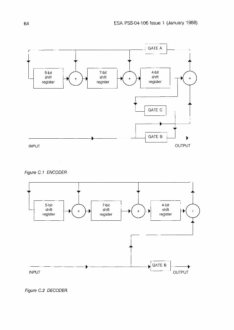
NOTE (1): See also Appendix C: Possible Realisation of a Frame Check Sequence Encoder-Decoder.
ESA PSS-04-106 Issue 1 (January 1988) 37
6. TELEMETRY TRANSMISSION PROTOCOLS
INTRODUCTION
The purpose of this section is to present the Packet Telemetry data structures and mechanisms at work. To achieve this, each procedural step of the corresponding data capture process on the ground is described and, where necessary, standard user guidelines and examples are provided.
There are four main procedural steps: (a) Transfer Frame Acquisition, with frame error control and master
contents verification and virtual channel frame accounting. (c) Telemetry Packet Extraction, with packet flow management and
accounting. (d) Source Packet Reconstruction, with packet source sequence verifica-
tion and accounting.
The procedures characterising each step are the subject of the following four subsections.
The particular problems associated with spacecraft time acquisition and calibration are covered separately in Section 7.
6.2 TRANSFER FRAME ACQUISITION
The Transfer Frame Acquisition Processor verifies the presence of the 32-bit Attached Synchronisation Marker at intervals of one Transfer Frame length plus 32 bits. In practice, these tests are performed over several successive specimens to allow for transmission errors in the Attached Synchronisation Marker. Then, the presence of errors in each Transfer Frame is detected by means of the Frame Error Control Word placed in the Transfer Frame Trailer, and each Frame is passed to the next process with a quality label GOOD or BAD.
When Reed-Solomon coding is used, these frame synchronisation and error detection tasks are performed by the Reed-Solomon decoder, using the R-S Attached Synchronisation Marker and the R-S code error syndrome exclusively.
The procedure finds its conclusion in the processing of the Primary Header of all GOOD Frames: 0 Verification of Version Number and Spacecraft ID (they must be as
specified). 0 Tracking of Master Channel Frame Count to monitor the quality of the
downlink data channel.
38 ESA PSS-04-106 Issue 1 (January 1988)
l Determination of the exact Transfer Frame Data Field length by verifying the presence of the optional Operational Control Field and standard Secondary Header (overall frame length is implied from Spacecraft ID value, as well as presence of Frame Error Control Word).
l If the Operational Control Field is present, further verification of the Command Link Control Word (CLCW) presence is performed and each found CLCW is transferred to the Packet Telecommand Processor.
6.3 VIRTUAL CHANNEL DEMULTIPLEXING
After acquisition, GOOD Transfer Frames enter the Virtual Channel Demultiplexing Processor, which can handle up to 8 discrete Virtual Channels (VCs). For each incoming frame, the following on-line processes take place: a Read-out of VC Identifier, in the Frame Identification field. l Verification of corresponding VC Frame Count sequence (VC Frame
accounting). This verification includes the case where a standard Secondary Header has been implemented to expand the VC Frame Count length.
l Read-out of the Synchronisation Flag of the Frame Data Field Status: (a) when the flag is set to ‘0’ (synchronous data) the frames of that VC
are transferred to the Telemetry Packet Extraction Processor for packet extraction. This is covered in Section 6.4.
(b) when the flag is set to ‘1’ (asynchronous/non-standard data) the frames of the VC are transferred to any specifically indicated processor or storage device. This is covered in Section 6.6.
For each VC, frame accounting will take into consideration the corresponding accounting data from the Transfer Frame Acquisition Processor.
6.4 EXTRACTION OF SYNCHRONOUSLY INSERTED TELEMETRY PACKETS
The Telemetry Packet Extraction Processor will extract synchronously inserted Telemetry Packets from the frames of up to 8 discrete VCs. For each incoming frame of a particular VC, the following Frame Data Field Status fields are processed on-line: l Packet Order Flag l Segment Length Identifier 0 First Header Pointer
ESA PSS-04-106 Issue 1 (January 1988) 39
6.4.1 ‘Forward’ Order
When the Packet Order Flag is set to ‘0’, the order of the Telemetry Packets synchronously inserted in the frame data field will be forward-justified (as defined in Section 5). THIS IS THE STANDARD CASE: a real-time Packet Telemetry VC will normally only contain forward-ordered, synchronously inserted Telemetry Packets.
In such a case, the Telemetry Packet Extraction Processor will read out the Segment Length Identifier and will proceed to extract the Telemetry Packets of that particular VC by interpreting the value of the First Header Pointer as indicated in Table 5.1 of Section 5: 0 ‘IDLE’ state: the frame is empty of data and the Telemetry Packet
extraction process of that VC is informed to wait until the next ‘ACTIVE’ state.
l ‘ACTIVE’ state: the frame contains standard, forward-ordered Telemetry Pat kets.
The Telemetry Packets must bear the correct Version Number, as specified in Section 4. The extraction process consists in extrapolating the position of each Telemetry Packet Header from the First Header Pointer value given in each Transfer Frame.
The main purpose of the First Header Pointer is to point directly to the location of the starting octet of the first header structure (when one is present) in the frame data field. When no header structure is present, owing to the length of the Telemetry Packet in the previous frame, this is indicated by the pointer value ‘all ones’.
The location of any subsequent headers will be determined by a ‘chaining’ procedure whereby the Packet Length and the Segmentation Flags within each header will be examined to determine where the following header begins, taking into account the Segment Length value (LSEGMENT) specified for the VC.
If the packetised data consist only of Telemetry Packets containing unsegmented source data, the ‘chaining’ process is straightforward, since the Packet Length field indicates the true length of the Packet Data Field. When Telemetry Packets contain segmented source data, the Packet Length field must be interpreted differently, as the states of the Segmentation Flags vary (see Sections 4 and 5 for the detailed specifications).
An example of a Source Packet segmentation process is illustrated in Figure 6.1, which shows how a Source Packet 2106 octets in overall length (2100 octets of Packet Data Field plus 6 octets of Packet Header) is progressively broken into four Telemetry Packets of length (LSEGMENT + 6 octets) - with LSEGMENT = 512 octets in the example - and a final Telemetry Packet of length 58 octets (52 + 6).
40 ESA PSS-04-106 Issue 1 (January 1988)
6 SOURCE PACKET = 2106 octets
H 2100
Segmentation Flags = ‘11’ Length = 2099
I I 6
H 512 FIRST TELEMETRY PACKET
Flags = ‘01’ LSEGMENT Length = 2099
CONTINUATION-l H 512
Flags = ‘(-JO’
Length = 1587
CONTINUATION-2
CONTINUATION-3
LAST TELEMETRY PACKET
Figure 6.1 EXAMPLE OF THE PACKET SEGMENTATION PROCESS
Finally, the Telemetry Packet Extraction Processor will examine the following Packet Header fields: l Application Process Identifier (AP ID). 0 Source Sequence Count.
The purpose of this verification is to: 0 ensure that Telemetry Packets containing the segments of the same
Source Packet are effectively identified by both identical AP IDS and Source Sequence Counts.
l discard Idle Packets, knowing that they are identified by the AP ID ‘all ones’.
ESA PSS-04-106 Issue 1 (January 1988) 41
USERS SHOULD NOTE THE FOLLOWING:
NOTE 1: Ground data systems implementation considerations will limit the number of different application processes that may be simultaneously undergoing segmentation during a given session.
NOTE 2: Idle Packets are inserted in a Telemetry Packet stream as one of the means of maintaining synchronisation of the packet extraction process during periods when no Source Packets are available on board the spacecraft for transfer to the ground. (Idle Packets are not to be confused with the IDLE state of a Virtual Channel Transfer Frame, which is another means of maintaining synchronisation.)
NOTE 3: The spaceborne data-management system of a particular mission may have to perform a minimum of protocol conformance checks on each collected Source Packet in order to meet the desired packet-delivery performance. The checks to be considered primarily concern the Packet Length field of each Source Packet Header. The Packet Length field must be consistent with the actual length of the Packet Data Field, as it would otherwise disrupt the chaining process used on the ground to extract the packets. It is also recommended that, whenever feasible, the correctness of AP ID’s be verified for each collected Source Packet.
6.4.2 ‘Reverse’ Order
The use of reverse-ordered, synchronously inserted Telemetry Packets is not considered by ESA. Consequently, this mode of operation is not supported by the ESA ground network. (See, however, the standard provision described in Section 6.6, which covers the same requirement.)
6.5 SOURCEPACKETRECONSTRUCTION
For up to eight discrete Virtual Channels, the Source Packet Recon- struction Processor will reconstruct the original Source Packets from the extracted Telemetry Packets. The procedure is very similar to that of the Telemetry Packet extraction process, and, in practice, both processes can be interrelated.
For each Application Process Identifier, the system will keep track of the continuity of the Sequence Control Count. Missing Source Packets will be signalled. Incompletely reconstructed Source Packets will still be delivered and their missing parts will be signalled.
42 ESA PSS-04-106 Issue 1 (January 1988)
6.6 EXTRACTION OF ASYNCHRONOUSLY INSERTED DATA
As indicated in Section 5 [paragraph 54.4 (b)], it will be a project responsibility to extract asynchronously inserted data from the frames of any VC.
However, a standard provision has been foreseen for the extraction of asynchronously inserted Transfer Frames. Typically, this situation occurs when the mission requirements make it necessary to store the source data in an on-board memory device (this can be a magnetic tape recorder, a bubble memory unit or any suitable recording device) so that it can be dumped later, usually at a speed higher than the recording speed, at a convenient time.
This standard recognizes one method for meeting the above requirement: 0 The recorded (stored) data shall be in the form of standard Transfer
Frames, typically those of the real-time physical channel at the time of recording with their Attached Synchronisation Markers.
l At playback time, the recorded Transfer Frames are dumped asynchronously into the data field of real-time Transfer Frames specially allocated for this purpose (dedicated playback VC).
0 The asynchronous insertion can be made in either the forward or the reverse mode. In the case of forward insertion, the presence of forward- justified Attached Synchronisation Markers in the data fields of the downlink Transfer Frames will probably not be acceptable because of the disruptions they will cause to the Transfer Frame synchronisation process on ground, particularly during acquisition. In this case, a second Synchronisation Marker pattern is required, as specified in Section 53.3.
l On the ground, the real-time VC used to dump the recorded Transfer Frames is processed, and its contents stored away. Then a second, off- line process takes place which consists in retrieving these contents in the correct, forward-justified direction, and in processing them as for any real-time physical channel.
l The ground process detailed above may require that each recorded Transfer Frame be tagged with a large count number for easy retrieval. This can be achieved (for each VC) with the standard 24-bit Virtual Channel Frame Counter extension contained in the optional Transfer Frame Secondary Header.
l If the Transfer Frames contain synchronously inserted, forward-ordered, standard Telemetry Packets, these will be extracted as described in Sections 6.4 and 6.5.
ESA PSS-04-106 Issue 1 (January 1988) 43
7. SPACECRAFT TIME PROTOCOLS
7.1 INTRODUCTION
The time code formats and procedures described in this section are directly extracted from Reference [5], which is concerned with the subject of spacecraft time.
All spacecraft are required to maintain a spacecraft reference time, called ‘Spacecraft Elapsed Time’, for the purpose of time-tagging telemetered events. The spacecraft clock is a free-running counter from an arbitrary starting point (epoch). The corresponding absolute time in the UTC (Universal Time Coordinated) reference frame is derived by ground correlation of the spacecraft clock. This correlation information is normally distributed, on the ground, together with the Source Packets. It can also be retransmitted to the spacecraft, should UTC be required by the spaceborne data systems as an additional service.
The three subsections which follow cover the following fields: a Presentation of Spacecraft Elapsed Time. 0 Format of standard Spacecraft Time Source Packet. 0 Spacecraft time-correlation procedures.
PRESENTATION OF SPACECRAFT ELAPSED TIME
The Spacecraft Elapsed Time is maintained by the central clock on board the spacecraft and made available to all users. The time code format used is the CCSDS Unsegmented Time Code (CUC) format, which is represented as a combination of a preamble field (P-field) and a time specification field (T-field). The P-field may be either explicitly or implicitly conveyed within the spacecraft time code. If it is explicitly conveyed, it shall immediately precede the T-field.
The general format of both fields is as follows: 0 P-field (1 octet): spacecraft time format specification. 0 T-field (1 to 7 octets): spacecraft time specification.
The Spacecraft Elapsed Time shall be represented as an unsegmented binary count of seconds and binary powers of subseconds, counting from an arbitrary epoch. The resolution can be 2’, 2-8, 2-16 or 2-24 seconds. The time shall be formatted as follows:
44 ESA PSS-04-106 Issue 1 (January 1988)
(a) P-Field:
bits 0 -3 = 0010
bits 4 -5 = no. of octets of coarse time, minus one; i.e. 1 to 4 octets.
bits 6-7 = no. of octets of fine time; i.e. 0 to 3 octets.
(b) Complete spacecraft time:
P-Field T-Field
00 100000 00100001 00100010 00100011
00100100 00100101 00100111 00100111
00101000 00101001 00101010 00101011
00101100 00101101 00101110 00101111
232 34
(c) Unit of time: TAI (Temps Atomique International) second.
(d) Epoch: arbitrary, i.e. the epoch is of no importance, since elapsed time samples are UTC correlated on ground (see following sections).
If spacecraft time information is needed as ancillary data for the interpretation of the Source Packet data, then time shall be inserted in the Data Field Header of the Source Packet Data Field.
The presence of time in a Data Field Header shall be application dependent. However, when present, the time field shall occupy the first
ESA PSS-04-106 Issue 1 (January 1988) 45
7.3
octets of the Data Field Header. The time code format used can be either that of the Spacecraft Elapsed Time (CUC) or that of the Spacecraft UTC (CCSDS Day Segmented time code (CDS)) when this additional service is provided on board the spacecraft
The P-field is optional, but its inclusion is mandatory whenever application-specific interpretation of the T-field is required.
The length of the T-field is application dependent, as required by the user. It can be smaller than the distributed central spacecraft time. If it must be longer, the additional clock octets shall be generated by the on-board user. In all cases, the length of the T-field shall be sufficient to avoid ambiguity during the mission, and the resolution shall be sufficient to meet the requirements of interpreting the data without additional processing of the time information.
STANDARD SPACECRAFT TIME SOURCE PACKET
The standard Source Packet used to transport the regular Spacecraft Elapsed Time samples to ground for time correlation with UTC will be formatted as follows:
l Application Process Identifier: ‘all zeros’ (reserved AP ID)
l Data Field Header Flag: set to ‘0’
l Packet Data Field: the data field of the standard Source Packet only contains spacecraft time system information formatted as follows:
(a) The first octet in the data field shall specify the sampling rate of the spacecraft clock contents as explained further in Section 7.4. The format and specification of this octet is as follows:
Bits 0, 1, 2, 3: Not specified in this Standard (to be obtained from the supporting infrastructure or to be set to ‘all zeros’ if not used).
Bits 4, 5, 6, 7: Specify the sampling rate of the spacecraft clock contents as described in Section 7.4. The code allocation is as follows:
46 ESA PSS-04-106 Issue 1 (January 1988)
Bit 4 Bit 5 Bit 6 Bit 7 Rate (in Frames)
1 1 0
0 1 1 2 0 4 1 8 0 16 1 32 0 64 1 128 0 256
(b) The next octets will contain spacecraft time information in the form of a P-field and a T-field, with length and contents as described in Section 7.2.
(c) The last octets will contain any relevant spacecraft time-system parameters, as required. This includes the provision of system configuration flags for the identification of the various fixed, on-board delays. The format for this part of the Packet Data Field shall be obtained from the supporting infrastructure.
7.4 SPACECRAFT TIME CORRELATION PROCEDURES
On board the spacecraft, the contents of the Spacecraft Elapsed Time clock are sampled at the instant of occurrence of the leading edge of the first bit of the Attached Synchronisation Marker of that telemetry Transfer Frame of Virtual Channel ‘0’ with a Virtual Channel Frame Count ‘0’. This time sample shall then be placed into the standard Spacecraft Time Source Packet and telemetered to ground before the Frame Counter of Virtual Channel ‘0’ has counted 255 more frames, so as to avoid ambiguity.
Should this sampling rate (intervals of 256 Frames of Virtual Channel ‘0’) prove too low for the mission requirements, it is permissible to sample the spacecraft clock contents at intervals of 128, 64, 32, 16, 8, 4, 2 or 1 frame(s) of Virtual Channel ‘O’, by choice. Consequently, the time sample shall be telemetered to ground before the selected number of Frames of Virtual Channel ‘0’ have elapsed (128, 64, 32, 16, 8, 4, 2 or 1, all counts starting from Virtual Channel Frame Count ‘0’).
The ground data capture system shall: (a) accurately time-tag the instant of reception of the same first bit of the
Attached Synchronisation Marker of the Virtual Channel ‘0’ Transfer Frame with a Virtual Channel Frame Count ‘0’. The time standard used will be CDS-coded UTC;
ESA PSS-04-106 Issue 1 (January 1988) 47
(b) extract the standard Spacecraft Time Source Packet and collect the CUC-coded time sample.
Thus, a correlation between the Spacecraft Elapsed Time and the UTC reference on ground shall be established, which can be used: 0 on ground, to transform the Spacecraft Elapsed Time information
contained in the source Packets into UTC information; 0 on board the spacecraft, to achieve directly the same service as on the
ground.
48 ESA PSS-04-106 Issue 1 (January 1988)
PAGE INTENTIONALLY LEFT BLANK
ESA PSS-04-I 06 Issue 1 (January 1988) 49
8. TELEMETRY DOWNLINK SIGNAL
8.1 GENERAL
The complete specification of the telemetry signals modulating the radio-frequency carrier shall be found in Reference [7].
8.2 BIT RATE
8.2.1 Range
Packet telemetry systems can nominally operate at bit rates (or symbol rates) from a few bits per second to several megabits per second. At any given time, the limitations on these rates are those imposed by the telemetry equipment in the ground stations of the ESA network. The detailed characteristics of this equipment shall be obtained from ESOC, Darmstadt (Germany).
8.2.2 Stability
(a) Encoding
The long- and short-term stability requirements depend on: 0 the spacecraft radio-frequency and modulation requirements; l the spacecraft time-correlation requirements, as described in Section 7.
(b) Tape Recorders
To be defined on a case-by-case basis.
50 ESA PSS-04-106 Issue 1 (January 1988)
PAGE INTENTIONALLY LEFT BLANK
ESA PSS-04-106 Issue 1 (January 1988) 51
9. TELEMETRY SERVICES AND PERFORMANCE REQUIREMENTS
9.1 OVERVIEW OF THE SERVICES
This Standard defines two data communications layers which, when combined, permit a full adaptive packet telemetry system to be realised, if required. These two data communications layers are: (a) The user data layer, with an end-to-end user data unit: the Source
Packet; and a data flow mechanism: Segmentation (with the Telemetry Packet).
(b) The space-to-ground transfer layer, with a link protocol data unit: the Transfer Frame; and a data flow mechanism: Virtual Channelisation.
For each of these two layers there exists a telemetry service. The two services are defined in this section and are part of the standard mission support provided by the ESA infrastructure. Any other mission-specific services must be considered on a case-by-case basis: they are outside the scope of this Standard.
Table 9.1 provides a quick-look description of the two services, which are defined in more detail in the following subsections. The table does not contain the front-end telemetry coding services (convolutional coding, Reed- Solomon coding) which are covered in Reference 2. However, where necessary, some information on these coding services is provided in this Standard.
9.2 SERVICE 1: SOURCE PACKET DELIVERY
9.2.1 Requirements
This service will be provided whenever the Transfer Frames of a Virtual Channel contain synchronously inserted, forward-ordered Telemetry Packets, as specified in this Standard.
9.2.2 Data Delivery
For the considered Virtual Channel, only GOOD (errorless) Transfer Frames are considered for packet extraction, as specified in Section 6.2 (Transfer Frame Acquisition). The GOOD/BAD (errorless/corrupted) information is obtained by making use of: l the Reed-Solomon check symbols, when Reed-Solomon coding is
used. l the Transfer Frame Error Control Word when Reed-Solomon coding is
not used.
52 ESA PSS-04-106 Issue 1 (January 1988)
SERVICE SERVICE NUMBER NAME
DESCRIPTION OF SERVICE
Requirements: Standard Transfer Frames with synchronous insertion of forward-ordered Telemetry Packets.
SOURCE Data Delivery: Source Packets: Telemetry Packets carrying (per Virtual segments are re-assembled and the Source Channel) Packets delivered when complete. Incomplete
Source Packets are also delivered, their missing 1 PACKET parts being signalled.
Spacecraft Time: Correlation of packetised spacecraft time with ground time is provided.
DELIVERY Telecommand: Standard Command Operation Procedure (COP-l) (real-time can be serviced by means of the CLCW, if this operations) option is retained.
Requirements: Standard Transfer Frames
TRANSFER Data Delivery 1: All correctly acquired (synchronised) Transfer (per Physical Frames, labelled GOOD/BAD. Channel)
2 FRAME Data Delivery 2: Only GOOD Transfer Frames (per Virtual Channel)
DELIVERY Spacecraft Time: First bit of each Attached Sync. Marker is time- tagged on ground
Telecommand: As for Service 1 (i.e., only for GOOD Frames) (real-time operations)
Table 9.1 MAIN TELEMETRY SERVICES
Frame accounting is provided (i.e., missing frames are signalled). All correctly reconstructed (complete) Source Packets are recorded. Subject to the data throughput characteristics of the communications link between the ground station and the recipient, the Source Packets will be delivered either on line or off line. Since each Source Packet is uniquely identified by an Application Process Identifier, any combination list of packets in a Virtual Channel can be sent to the designated recipient. By virtue of this selection capability, the on-line transmission of telemetry-user data between the ground station and the recipient (e.g., operations control centre) can be adapted to the ground transmission constraints. Also, packet accounting is
ESA PSS-04-106 Issue 1 (January 1988) 53
provided, (i.e., missing or incomplete packets are signalled). Telemetry Packets carrying the segments of a long Source Packet will
be reassembled and processed by the ground station, so that the Source Packet can be delivered. If the reconstitution process fails, incomplete Source Packets will still be delivered and their missing parts will be signalled.
9.2.3 Spacecraft Time
The time of arrival, at the ground station, of all Transfer Frames is accurately measured by time-tagging the first bit of each Attached Synchronisation Marker. Furthermore, the standard Telemetry Packet containing the spacecraft time sample will be extracted from the appropriate Virtual Channel (normally Virtual Channel ‘0’; see Section 7 for details on spacecraft time sampling methods). All these elements of time information are then processed and the subsequent time correlation information delivered to the recipients together with their packetised data.
9.2.4 Telecommand
The standard Command Operation Procedure (COP-l), as defined in Reference [4], will be serviced by means of the Command Link Control Word (CLCW) if this optional report is contained in the Transfer Frames. Only GOOD Transfer Frames are considered for CLCW extraction.
9.3 SERVICE 2: TRANSFER FRAME DELIVERY
9.3.1 Requirements
This service can be provided whenever standard Transfer Frames are used. Typically, this service is required: 0 when the synchronously inserted user-data units are not standard,
forward-ordered Telemetry Packets, or 0 when the asynchronously inserted user-data units are not standard
Transfer Frames (playback data).
9.3.2 Data Delivery
(a) Data delivery 1
For the considered Physical Channel, all acquired Transfer Frames are recorded, each being tagged as a GOOD or BAD Transfer Frame. The GOOD/BAD information is obtained as for Service 1, that is, by making use of:
54 ESA PSS-04-106 Issue 1 (January 1988)
0 the Reed-Solomon check symbols when Reed-Solomon coding is used; 0 the Transfer Frame Error Control field when Reed-Solomon coding is not
used.
The user data contained in the Transfer Frames are not extracted: this responsibility lies with the recipient. Subject to the data throughput between the ground station and the recipient, the Transfer Frames will be either delivered in real time or played back at a convenient time and speed.
(b) Data Delivery 2
For any specific Virtual Channel, only GOOD Transfer Frames are recorded. In all cases, frame accounting is provided (i.e., missing Transfer Frames are signalled for each serviced Virtual Channel).
This is the data delivery service used locally by the ESA ground network for extracting asynchronously inserted Transfer Frames from a real- time Virtual Channel (standard provision for playback data). The so-obtained stream of playback Transfer Frames is then processed off line as any real- time physical data channel.
Other non-standard cases are serviced in a manner similar to that of Data Delivery 1, i.e. the user data contained in the Transfer Frames of the specific Virtual Channel are not extracted: this responsibility lies with the recipient. Subject to the data throughput between the ground station and the recipient, the Transfer Frames will be either delivered in real time or played back at a convenient time and speed.
9.3.3 Spacecraft Time
As indicated for Service 1, all Transfer Frames are accurately time- tagged upon arrival at the ground station. This time information is delivered to the recipient with each Transfer Frame of the specified Virtual (or Physical) Channel.
9.3.4 Telecommand
As per Service 1 (that is, only for GOOD Transfer Frames).
9.4 PERFORMANCE REQUIREMENTS
Packet Telemetry data link protocols are based on forward error correction techniques so as to provide the data capture processes on ground with information units (the Transfer Frames) that are deemed to be either GOOD (errorless) or BAD (corrupted, therefore not used).
ESA PSS-04-106 Issue 1 (January 1988) 55
With Packet Telemetry systems, the quality of service must be defined as the desired probability of Source Packet delivery (PPD), from which a probability of Source Packet loss (PPL) can be derived after the average Source Packet size (PS) and the selected Transfer Frame size (FS) have been established. From the probability of Source Packet loss, the key parameter can now be derived: the probability of Transfer Frame loss (PFL), which is related to a given BER, and hence to the minimum Eb/No required for the downlink. The relationship between BER and E,/N, is dependent on the characteristics of the physical data channel and on those of the coding techniques used on this channel: a no coding (Transfer Frame alone) l Reed-Solomon coding (bandwith x 1 .12) 0 convolutional coding (bandwidth x 2) a Reed-Solomon coding concatenated with convolutional coding
(bandwidth x 2.24).
The coding techniques listed above are in step with recently emerging technology, and they are fully supported by instrumentation developed both for the spacecraft (e.g. chip-based Reed-Solomon encoder) and for the ground network (Viterbi and Reed-Solomon decoders).
The recommended approach is to make the downlink data channel as ‘clean’ as possible,if necessary by applying coding. The required performance curves and the formulation of the method of using them is to be found in Appendix D: Performance of Various Channel Coding Techniques.
56 ESA PSS-04-106 Issue 1 (January 1988)
PAGE INTENTIONALLY LEFT BLANK
ESA PSS-04-106 Issue 1 (January 1988) 57
10. COMPATIBILITY WITH OTHER GROUND NETWORKS
This Standard is a derived subset of Reference [I]. At the time of issue of this Standard, the various Agencies participating in the CCSDS have only recently started their plans for defining compatible agency-specific standards. It is expected that the potential for cross-support will considerably increase during the coming decades.
ESA missions requiring support from other agencies’ ground networks are cautioned to negotiate the exact level of compatibility between these networks and their spacecraft systems.
Non-ESA missions conforming to CCSDS-derived Packet Telemetry standards issued by other Agencies, and requiring support from the ESA ground network, are also cautioned to negotiate the exact level of compatibility between their spacecraft systems and the ESA network. In many instances, the ESA network may readily (or at little cost) cover aspects of the CCSDS Recommendations which have not been retained in this Standard.
ESA PSS-04-106 Issue 1 (January 1988)
PAGE INTENTIONALLY LEFT BLANK
ESA PSS-04-106 Issue 1 (January 1988) 59
APPENDIX A CORRESPONDENCE WITH CCSDS TERMINOLOGY
Although this Standard is directly derived from Reference [l], some of its terms are different, and the correspondence between these terms is as follows:
ESA STANDARD CCSDS RECOMMENDATION
Source Pat ket Header Source Packet Data Field Header Source Packet Data Field Telemetry Packet Octet No. ‘0’
Source Packet Primary Header Source Packet Secondary Header - no formal term - Telemetry Segment Octet # 1
RATIONALE
Source Packet Header
Since the ESA term for the CCSDS Source Packet Secondary Header’ is ‘Data Field Header’, the word ‘Primary’ cannot be used.
Source Data Field Header
The name of this Header indicates that its contents are strictly related to the Source Data, and are not meant (as the CCSDS term Secondary Header’ would imply) to be used for extending the Source Packet (Primary) Header Services.
Source Packet Data Field
This term is used by ESA to describe that part of the Source Packet structure which is defined by the Packet Length field. The CCSDS Recom- mendation (Reference [l]) does not formally identify that part of the packet structure.
Telemetry Packet
In this Standard, only one term could have been used to designate the packet structure: ‘Telemetry Packet’. Indeed, only one CCSDS packet structure is used in this document: the Version 2 Telemetry Segment, which ESA chooses to call, more conveniently, Telemetry Packet.
60 ESA PSS-04-106 Issue 1 (January 1988)
For reasons of convenience, in particular for the (source) user, the term Source Packet’ has been kept to indicate a subset of the more general term ‘Telemetry Packet’.
0 Octet No. ‘0'
In this Standard, the octet numbering convention is aligned with that used for bit numbering. In Reference [l], this is not so, in particular as regards the First Header Pointer specification (‘P’).
ESA PSS-04-106 Issue 1 (January 1988) 61
APPENDIX 6 SELECTION AND PERFORMANCE OF TRANSFER FRAME
SYNCHRONISATION MARKERS
A study was performed, at the instigation of the CCSDS, to determine a pair of Transfer Frame synchronisation markers with relatively low false alarm probability when these patterns were auto-correlated or pairwise cross-correlated.
Several 32-bit patterns were selected for testing. Each of these patterns had already been recommended previously by some other standardisation group or agency, such as IRIG and NASA.
The tests included auto-correlation of each pattern with itself, with its complement, with its reverse (or mirror), and with the reverse complement.
For each of the above tests, each pattern was permuted or rotated through each of the 32 possible starting points, and the rotation resulting in the lowest probability of false alarm was chosen.
Since there is a possibility that a second, imbedded pattern may be needed in some applications (e.g., imbedded frames from merged tape recorder playback) these tests were repeated for all pair combinations for minimum cross-correlation.
As a result of the above-mentioned tests, the following pair of 32-bit synchronisation markers was recommended:
SYNC MARKER 1 (hexadecimal) = 1 A C F F C 1 D
SYNC MARKER 2 (hexadecimal) = 3 5 2 E F 8 5 3
The probabilities of false alarm for the best rotation (autocorrelation performance) of each pattern is given in Table B.l, together with the probability of false alarm for the pair (cross-correlation performance). Pl, P2, P3 and P4 are the false alarm probabilities corresponding to channel bit error probabilities of IO-‘, IO-‘, 10m3 and 10e5 respectively.
AUTO-CORRELATION - SYNC MARKER 1 - SYNC MARKER 2
CROSS-CORRELATION OF PAIR 1, 2
Pl x lo4
0.16 0.13
0.10
P2 x lo4
0.04 0.08
0.02
P3 x lo4
0.03 0.08
0.02
P4 x lo4
0.03 0.09
0.02
TABLE B. 1 AUTO- AND CROSS-CORRELATION PERFORMANCE
62 ESA PSS-04-106 Issue 1 (January 1988)
PAGE INTENTIONALLY LEFT BLANK
ESA PSS-04-106 Issue 1 (January 1988) 63
APPENDIX C POSSIBLE REALISATION OF A FRAME CHECK SEQUENCE
ENCODER - DECODER
This Appendix describes two possible arrangements, based on a shift register, for encoding and decoding a Transfer Frame according to the Frame Check Sequence procedures defined in Section 5.
c.1 ENCODER
Figure C.l shows a possible arrangement for encoding using a shift register. To encode, the storage stages are set to ‘one’, gates A and B are enabled, gate C is inhibited, and (n-16) message bits are clocked into the input. They will appear simultaneously at the output.
After the bits have been entered, the output of gate A is clamped to ‘zero’, gate B is inhibited, gate C is enabled, and the register is clocked a further 16 counts. During these counts, the required check bits will appear in succession at the output.
c.2 DECODER
Figure C.2 shows a possible arrangement for decoding using a shift register. To decode, the storage stages are set to ‘one’, and gate B is enabled.
The received n bits (i.e., the (n-16) message bits plus the 16 bits of FCS) are then clocked into the input and after (n-16) counts gate B is inhibited. The 16 check bits are then clocked into the input and the contents of the storage stages are then examined. For an error-free block, the contents will be ‘zero’. A non-zero contents indicates an erroneous block.
64 ESA PSS-04-106 Issue 1 (January 1988)
5bit shift
register
A GATE
v
7-bit 4-bit shift shift
register register
\r AL
_ GATE C _
INPUT OUTPUT
Figure C. 1 ENCODER.
I register
INPUT
b OUTPUT
Figure C.2 DECODER.
ESA PSS-04-106 Issue 1 (January 1988)
APPENDIX D PERFORMANCE OF VARIOUS CHANNEL CODING TECHNIQUES
This appendix supplements Section 9.4 (Performance Requirements) of this Standard. It is concerned with the formulation of the method introduced in Section 9.4 for the calculation of the minimum Er,/No (energy per bit/ noise power density) required to achieve the desired probability of Source Packet delivery.
When a Packet Telemetry system is to be defined, three parameters must first be considered: l the desired probability of Source Packet delivery: PPD l the selected (average) Source Packet size (in bits): PS l the selected Transfer Frame size (in bits): FS
If PPL is the probability of Source Packet loss, one can write:
PPL = 1 - PPD
PPL, when expressed as a function of the probability of Transfer Frame loss, PFL, is bounded by:
PFL depends not only on Er,/No, but also on the system architecture and the channel model considered. We assume that the channel is corrupted only by additive, white, Gaussian noise, and shall consider four cases:
l PSK Coherent biphase PSK (no coding)
l R-S PSK and standard Reed-Solomon (255,223) block code with I codewords per frame
l VD PSK with eight-level quantisation and standard (l/2 rate, k= 7) convolutional code with Viterbi decoding
l VD+R-S Concatenated VD and R-S with interleaving degree I
66 ESA PSS-04-106 Issue 1 (January 1988)
(a) PSK
PFL is given by:
PFL = 1 - (1 - pe)FS (D.2)
where pe is the bit error probability (after the demodulator). For small values of pe, PFL can be approximated by:
PFL < pe x FS (D.3)
The probability pe can be obtained from Figure D.1.
(b) R-S
PFL is given by:
PFL = 1 - (1 - pRS)’ 04)
where pRS is the probability of decoding failure for an R-S codeword, i.e. more than 16 symbol errors occur in the codeword, and I is the number of codewords in the frame.
pRS is given by:
PRS = 1 -
where pb is the symbol error probability, which is related to pe by:
Pb = 1 - (1 - Pe)”
For small values of pe, (D.6) can be approximated by:
(D.5)
(D.6)
Pb 2: 8 Pe
and for small values of 17 symbol errors. distribution, we get:
P.7)
of pb (< 10 -*), pRS can be approximated by the probability Using the Poisson distribution to approximate the binomial
ESA PSS-04-106 issue 1 (January 1988) 67
PRS (255 PbY7 z e-255Pb
17!
and
PFL = 5.16 x 10⁴’ x /pA7 e-2040pe ~5.2 x 10⁴’ x /pA7
PFL is given by:
PFL = 1 - (1 - pev)FS
P.8)
(W
(D.10)
where pev is the probability that an error event starts in a given position in the frame. pev can be related to the well-known first error event probability PE,, (Ref. [A], Chapter 9) by noticing that pev equals PE,,, provided no error event has occurred in the immediately preceding position. Since error events are assumed to be rare, pev can be approximated by I+,. Analytical expressions for PE,, are not known, but an upper bound can be derived using Viterbi’s method (see, for example, Ref. [A], Chapter 9) and written in the form:
where
Y = c ~P0/l0)P(YIV
(D.11)
(0.12)
characterises the symmetric, binary input, 8-ary output channel with output alphabet y, and Ai is the number of fundamental paths of weight i.
For the standard convolutional code (l/2 rate, k= 7) we have (Ref. [B]):
Ai = Ofori< 10andiodd
A,0 = 11, A,2 = 38, A,4 = 193, A,6 = 1331
such that
&I 5 11 Y lo + 38 y12 + 193 y14 + 1331 y16 + ,., (D.13)
68 ESA PSS-04-106 Issue 1 (January 1988)
In a similar way, an upper bound on the average bit error probability P, can be derived (Ref. [A], Chapter 9):
P, < c B; yi I 368” + 211 y12 + 1404 y14 + 11633 y= + . . . (D.14)
i=l
where Bj is the total of .weights for input sequences generating fundamental paths of weight i, and the numbers in Eq. (D.14) are taken from Reference [B].
Although it might be questionable to relate PE,, to P, on the basis of bounds for the two quantities, we find that since the two bounds are derived in similar ways, a reasonable approximation is achieved by setting P, = 3 PE,, and then using the approximation:
PFL = P, x FS
3 (D.15)
(d) VD +
errors
The probability P, can be obtained from Figure D.1.
R-S
In this case useful analytical expressions are difficult to derive, because from the Viterbi decoder appear in bursts. Thus Eq. (D.4) is valid only if I
is large enough to ensure that no single burst hits more than one byte in an R-S codeword. This is almost true for I = 8, and to a reasonable degree for I I 4. With I 1 4, Eq. (D.5) can also be considered as a good approximation, when pb is interpreted as the average symbol error probability. pb can be approximated by the error event probability PE, which is the probability that the decoder is off the correct path at a certain position, and an upper bound on PE can be calculated in a way similar to that in which P E,l and P, are calculated (Ref. [A], Chapter 9), i.e.:
(D.16)
where Cj is the total of lengths for input sequences generating fundamental paths of weight i. The Ci’S cannot be found in Reference [B], but by rough estimates we arrive at values indicating:
PE = 3P, (D.17)
ESA PSS-04-106 Issue 1 (January 1988) 69
and this is consistent with simulations that show symbol error probabilities 2.5 to 3 times greater than P,. Using again the Poisson distribution for small values of P, (110-3) to approximate the binomial distribution and assuming I = 8, we arrive at:
PFL = 8(765 PeY7 -765 p,
e 17!
= 2.4 x 1O35 Pe17 e-765 fe < 2.4 x 1O35 Pe17 (D.18)
For smaller values of I, we recommend that the required &/No be increased by a small amount, say 0.2 dB for I = 4 and 0.4 dB for I = 1.
Finally, three figures (D.2, D.3 and D.4) are provided, which give a direct reading of PFL against EbINo for the four channel cases, with various Transfer Frame lengths and interleaving depths. The error probabilities in all figures have been either simulated (high error probabilities) or extrapolated from the simulated ones (low error probabilities).
References:
[A] R.J. McEliece, ‘The Theory of Information and Coding’, Encyclopedia of Mathematics and its Applications, Vol. 3, Addison-Wesley 1977.
[B] A.J. Viterbi et al., ‘Concatenation of Convolutional and Block Codes - Final Report’, Tech. Report N71-32505, Nat. Tech. Inf. Service, U.S. Dep. of Corn. 1971.
ESA PSS-04-106 Issue 1 (January Annn’ I YUU)
I I I I I I I 4
0 2 4 6 8 10 12 14' 10 log E,,/No (dB)
0 -1
0-*
0 -3
0 -4
0 -5
0 -6
0 -7
0 -8
O-g
0 -10
0 -11
o-12
w 0 CK CK W
I-
m
IL 0
t- I- I
m a
m
0 Q1 a.
Figure D.l. PROBABILITY OF BIT ERROR VERSUS EbINo AT THE OUTPUT OF THE PSK DEMODULATOR (pe) AND THE VITERBI DECODER (P,)
ESA PSS-04-106 Issue 1 (January 1988) 71
VD+’
I I I I I
0 2 4 6 8 10 12 12' -12
VD
10 log Eb/No (dB)
10 -1
10 -2
10 -3
10 -4
10 -5
10 -6
10 -7
10 -8
10 -9
10 -10
10 -11
z L
m a
m 0 OL Q,
Figure D.2. PROBABILITY OF TRANSFER FRAME LOSS PFL VERSUS Eb/No FOR VARIOUS CHANNEL MODELS WITH FS = 255 OCTETS (I = 1)