40
Page 1 of 40

Page 1 of 40

Page 2 of 40

Page 3 of 40

Page 4 of 40
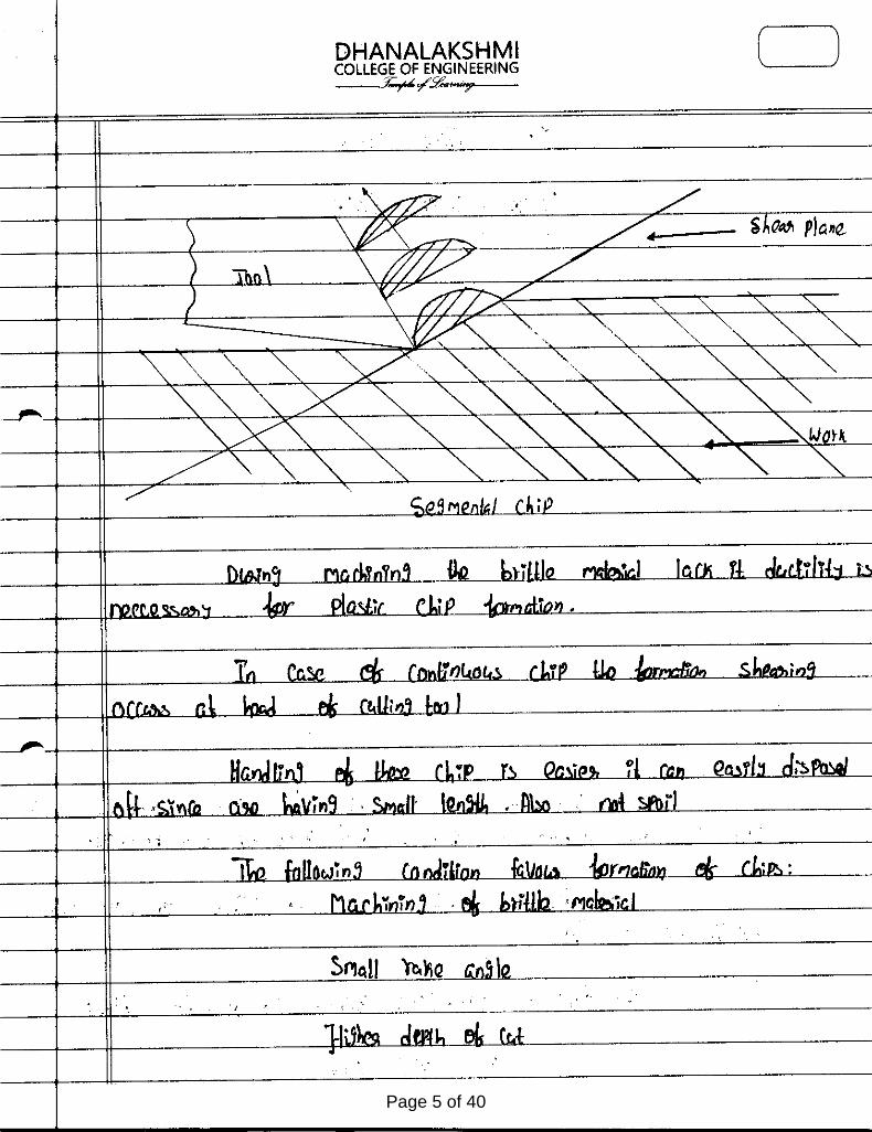
Page 5 of 40

Page 6 of 40

Page 7 of 40

Page 8 of 40

Page 9 of 40

Page 10 of 40
Page 11 of 40

Page 12 of 40

Page 13 of 40

Page 14 of 40

Page 15 of 40

Page 16 of 40

Page 17 of 40

Page 18 of 40

Page 19 of 40

Page 20 of 40

Page 21 of 40

Page 22 of 40

Page 23 of 40

Page 24 of 40

Page 25 of 40

Page 26 of 40

Page 27 of 40

ME 6402 - MANUFACTURING TECHNOLOGY II
UNIT –4 - ABRASIVE PROCESS AND BROACHING
l. What is meant by Grinding? A/M-12
Grinding is a metal removal process or operation performed by means of rotating abrasive
wheel that acts as a cutting tool against the work piece.
2. Why is grinding called finishing process? M/J 16
Grinding is called finishing process, because the grinding process removes metal usually in
the order of 0.25 to 0.50 mm, which produces very high quality surface finish.
3. What is the approximate thickness of metal removed in grinding operation ? M/J 15
The approximate thickness of metal removed in grinding operation is 0.01 to 0.03 mm.
4. What are the main types of grinding? A/M-12
The two main types of grinding are
1) Rough or Non -precision grinding and 2) Precision grinding.
5. What are the different types of rough grinders? M/J 14
The different types of rough grinders are
1. Floor stand and bench type grinders
2. Portable and flexible shaft grinders
3. Swing frame grinders and
4. Abrasive belt grinders.
6. What are the types of precision grinders? A/M-13
The different types of precision grinders are
1. Cylindrical grinders 2. Internal grinders 3. Surface grinders 4. Tool and cutter grinders
and 5. Special grinding machines
Page 28 of 40

7. What is surface grinding? M/J 11
Surface grinding is the process of producing and finishing flat surfaces by means of a
grinding machine using a revolving abrasive wheel.
8. What are the types of surface grindings? M/J 11
The different types of surface grindings are:
1. Reciprocating table surface grindings-
a. Horizontal type b. Vertical type.
2. Rotating table.-
a. Horizontal spindle b. Vertical spindle.
9. What types of work can be ground by a surface grinder? A/M-10
Surface grinder can be used for flat surface, irregular surface, curved surface, tapered surface,
convex surface and concave surface.
10. What are the types of internal grinders? A/M-16
The different types of internal grinders are:
1. Chucking grinders
a) Plain
b) Universal
2. Planetary grinders
3. Centre less grinders
1
. 1. Explain the working mechanism of cylindrical and surface grinding. ( A/M-11)
The cylindrical grinder is a type of grinding machine used to shape the outside of an object. The
cylindrical grinder can work on a variety of shapes; however the object must have a central axis
of rotation. This includes but is not limited to such shapes as a cylinder, an ellipse, a cam, or
a crankshaft.
Cylindrical grinding is defined as having four essential actions:
Page 29 of 40

1. The work (object) must be constantly rotating
2. The grinding wheel must be constantly rotating
3. The grinding wheel is fed towards and away from the work
4. Either the work or the grinding wheel is traversed with respect to the other.
While the majority of cylindrical grinders employ all four movements, there are grinders that
only employ three of the four actions.
Outside diameter grinding
OD grinding is grinding occurring on external surface a of an object between the centers. The
centers are end units with a point that allow the object to be rotated. The grinding wheel is also
being rotated in the same direction when it comes in contact with the object. This effectively
means the two surfaces will be moving opposite directions when contact is made which allows
for a smoother operation and less chance of a jam up.
Inside diameter grinding
ID grinding is grinding occurring on the inside of an object. The grinding wheel is always
smaller than the width of the object. The object is held in place by a collet, which also rotates the
object in place. Just as with OD grinding, the grinding wheel and the object rotated in opposite
directions giving reversed direction contact of the two surfaces where the grinding occurs.
Centerless grinding
Centerless cylindrical grinder
A schematic of the centerless grinding process.
Centerless grinding is a form of grinding where there is no collet or pair of centers holding the
object in place. Instead, there is a regulating wheel positioned on the opposite side of the object
to the grinding wheel. A work rest keeps the object at the appropriate height but has no bearing
Page 30 of 40

on its rotary speed. The workblade is angled slightly towards the regulating wheel, with the
workpiece centerline above the centerlines of the regulating and grinding wheel; this means that
high spots do not tend to generate corresponding opposite low spots, and hence the roundness of
parts can be improved. Centerless grinding is much easier to combine with automatic loading
procedures than centered grinding; throughfeed grinding, where the regulating wheel is held at a
slight angle to the part so that there is a force feeding the part through the grinder, is particularly
efficient.
Surface grinding is used to produce a smooth finish on flat surfaces. It is a widely used abrasive
machining process in which a spinning wheel covered in rough particles (grinding wheel) cuts
chips of metallic or nonmetallic substance from a workpiece, making a face of it flat or smooth.
Surface grinding is the most common of the grinding operations. It is a finishing process that
uses a rotating abrasive wheel to smooth the flat surface of metallic or nonmetallic materials to
give them a more refined look or to attain a desired surface for a functional purpose.
The surface grinder is composed of an abrasive wheel, a workholding device known as a chuck,
and a reciprocating or rotary table. The chuck holds the material in place while it is being worked
on. It can do this one of two ways: ferromagnetic pieces are held in place by a magnetic chuck,
while non-ferromagnetic and nonmetallic pieces are held in place by vacuum or mechanical
means. A machine vise (made from ferromagnetic steel or cast iron) placed on the magnetic
chuck can be used to hold non-ferromagnetic workpieces if only a magnetic chuck is available.
Factors to consider in surface grinding are the material of the grinding wheel and the material of
the piece being worked on.
Typical workpiece materials include cast iron and mild steel. These two materials don't tend to
clog the grinding wheel while being processed. Other materials are aluminum, stainless steel,
brass and some plastics. When grinding at high temperatures, the material tends to become
weakened and is more inclined to corrode. This can also result in a loss of magnetism in
materials where this is applicable.
The grinding wheel is not limited to a cylindrical shape and can have a myriad of options that are
useful in transferring different geometries to the object being worked on. Straight wheels can be
dressed by the operator to produce custom geometries. When surface grinding an object, one
must keep in mind that the shape of the wheel will be transferred to the material of the object like
a reverse image.
Spark out is a term used when precision values are sought and literally means "until the sparks
are out (no more)". It involves passing the workpiece under the wheel, without resetting the
depth of cut, more than once and generally multiple times. This ensures that any inconsistencies
in the machine or workpiece are eliminated.
Page 31 of 40

2. Describe gear cutting by forming and shaping. A/M-15
Gear manufacturing refers to the making of gears. Gears can be manufactured by a variety of
processes, including casting, forging, extrusion, powder metallurgy, and blanking. As a general
rule, however, machining is applied to achieve the final dimensions, shape and surface finish in
the gear. The initial operations that produce a semifinishing part ready for gear machining as
referred to as blanking operations; the starting product in gear machining is called a gear blank.
Selection of materials
The gear material should have the following properties:
High tensile strength to prevent failure against static loads
High endurance strength to withstand dynamic loads
Low coefficient of friction
Good manufacturability
Gear forming
In gear form cutting, the cutting edge of the cutting tool has a shape identical with the shape of
the space between the gear teeth. Two machining operations, milling and broaching can be
employed to form cut gear teeth.
Page 32 of 40

Form milling
In form milling, the cutter called a form cutter travels axially along the length of the gear tooth at
the appropriate depth to produce the gear tooth. After each tooth is cut, the cutter is withdrawn,
the gear blank is rotated, and the cutter proceeds to cut another tooth. The process continues until
all teeth are cut.
Broaching
Broaching can also be used to produce gear teeth and is particularly applicable to internal teeth.
The process is rapid and produces fine surface finish with high dimensional accuracy. However,
because broaches are expensive and a separate broach is required for each size of gear,this
method is suitable mainly for high-quality production.
Gear generation
In gear generating, the tooth flanks are obtained as an outline of the subsequent positions of the
cutter, which resembles in shape the mating gear in the gear pair. There are two machining
processes employed shaping and milling. There are several modifications of these processes for
different cutting tool used.
Gear hobbing
Gear hobbing is a machining process in which gear teeth are progressively generated by a series
of cuts with a helical cutting tool. All motions in hobbing are rotary, and the hob and gear blank
rotate continuously as in two gears meshing until all teeth are cut.
Finishing operations
As produced by any of the process described, the surface finish and dimensional accuracy may
not be accurate enough for certain applications. Several finishing operations are available,
including the conventional process of shaving, and a number of abrasive operations,
including grinding, honing, and lapping.
Page 33 of 40
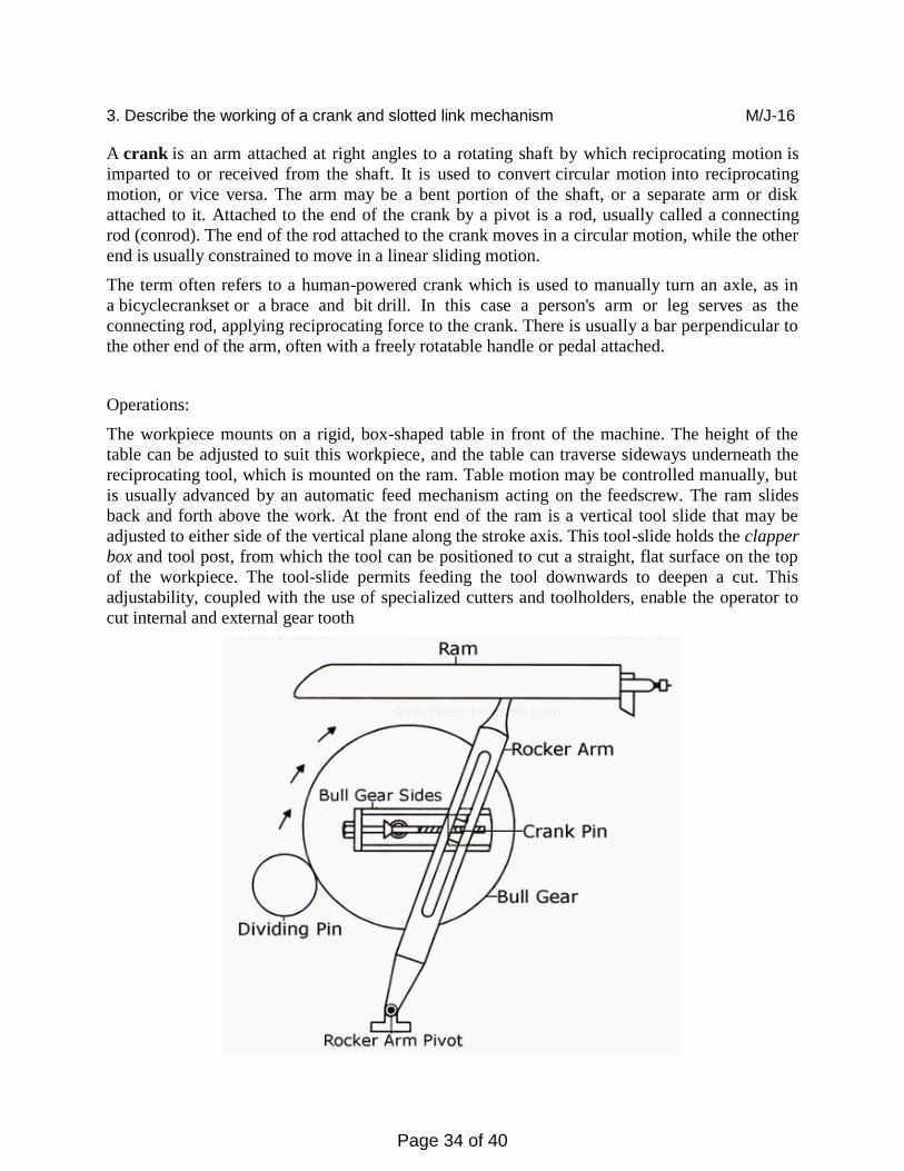
3. Describe the working of a crank and slotted link mechanism M/J-16
A crank is an arm attached at right angles to a rotating shaft by which reciprocating motion is
imparted to or received from the shaft. It is used to convert circular motion into reciprocating
motion, or vice versa. The arm may be a bent portion of the shaft, or a separate arm or disk
attached to it. Attached to the end of the crank by a pivot is a rod, usually called a connecting
rod (conrod). The end of the rod attached to the crank moves in a circular motion, while the other
end is usually constrained to move in a linear sliding motion.
The term often refers to a human-powered crank which is used to manually turn an axle, as in
a bicyclecrankset or a brace and bit drill. In this case a person's arm or leg serves as the
connecting rod, applying reciprocating force to the crank. There is usually a bar perpendicular to
the other end of the arm, often with a freely rotatable handle or pedal attached.
Operations:
The workpiece mounts on a rigid, box-shaped table in front of the machine. The height of the
table can be adjusted to suit this workpiece, and the table can traverse sideways underneath the
reciprocating tool, which is mounted on the ram. Table motion may be controlled manually, but
is usually advanced by an automatic feed mechanism acting on the feedscrew. The ram slides
back and forth above the work. At the front end of the ram is a vertical tool slide that may be
adjusted to either side of the vertical plane along the stroke axis. This tool-slide holds the clapper
box and tool post, from which the tool can be positioned to cut a straight, flat surface on the top
of the workpiece. The tool-slide permits feeding the tool downwards to deepen a cut. This
adjustability, coupled with the use of specialized cutters and toolholders, enable the operator to
cut internal and external gear tooth
Page 34 of 40

The ram is adjustable for stroke and, due to the geometry of the linkage, it moves faster on the
return (non-cutting) stroke than on the forward, cutting stroke. This action is via a slotted
link (or Whitworth link).
Types:
Shapers are mainly classified as standard, draw-cut, horizontal, universal, vertical, geared, crank,
hydraulic, contour and traveling head, with a horizontal arrangement most common. Vertical
shapers are generally fitted with a rotary table to enable curved surfaces to be machined (same
idea as in helical planing). The vertical shaper is essentially the same thing as a slotter (slotting
machine), although technically a distinction can be made if one defines a true vertical shaper as a
machine whose slide can be moved from the vertical. A slotter is fixed in the vertical plane
Page 35 of 40

MANUFACTURING TECHNOLOGY II
UNIT – 5 (CNC MACHINING)
1. Define numerical control machine. A/M-12
Numerical control can be defined as a form of programmable automation in which the
process is controlled by numbers, letters and symbols.
2. List out any threebasic components of NC system. M/J 16
1.Program of instruction 2.Controllerunit 3.Machine tool
3. Classify NC Motion Control System. A/M-12
1.Point to point 2. straight Cut 3.Contouring
4. Mention any three applications of Numerical control. M/J 15
1 .Milling 2.Drilling 3 .Boring
5. What is NC part programming? A/M-12
NC part programming is the procedure of by which the sequence of
processing steps to be performed on the NC machine is planned
and documented.
6. What is tape reader? M/J 15
The tape reader feed the data from the tape to the buffer in blocks.
7. What are the functions in computer assisted part programming? M/J 14
1 .Defining the work part geometry, 2. Specifying the operation
sequence and tool path.
8. What is APT language? A/M-12
APT is not only a NC language it is also the computer program that
performs the calculations to generate cutter positions based on APT
statement.
9. Classify statements in APT. M/J 14
1. Geometry statement 2. Motion statement 3.Post processor
statement 4. Auxilary Statement
10. Define - Check surface M/J 16
This is the surface that stops the movement of the tool in its
current direction.In a sense,the forward movement of the tool.
Page 36 of 40

11101 Explain the following in CNC machining. M/J 15
(a)Linear Interpolation
(b)Circular Interpolation
(c )Cubic interpolation LINEAR INTERPOLATION ALGORITHM
Any line in 3D space can be decomposed into three planes by dropping perpendiculars into each plane. This line is then equal to lines traced in any of two planes. Thus the 3D linear interpolation becomes two 2D linear interpolations. This principle forms the basis of our interpolation algorithm. 3D Line Movement In Space
We define the axis as long axis which has the longest distance movement in our 3D interpolation process. We call the other two axes as short axis. As shown in the figure 1, space line from O to P can be decomposed in 3 ways: OB and OC, or OB and OA, or OA and OC. The decomposition method of the space movement is decided by long axis. If Z axis is the long axis, the linear movement OP is decomposed into OB in XOZ plane and OC in YOZ plane. The interpolation algorithm starts by outputting a pulse train to the long axis and the driving pulses of two short axes depends on the relationship of the corresponding axis with the long axis. Thus two concurrent 2D interpolation movements of lines OB and OC implements the 3D linear interpolation of line OP.
3-D Line movement in XYZ
Circular Interpolation G02 G03 I, J, K Concepts & Programming
The axis of the Arc must be parallel to the X-, Y- or Z-axis of the machine coordinate
system. The axis or the plane perpendicular to the axis is selected with G17 (Z-axis, XY-
plane), G18 (Y-axis, XZ-plane) or G19 (X-axis, YZ-plane). I, J and K are the offsets from the
current location. At one time only two of I, J, and K will be used. This will depend on what
arc plane has been selected
G17 – Use I and J
G18 – Use I and K
G19 – Use J and K
The I, J and K arguments specify the DISTANCE from the ARC START POINT to the CENTER POINT of the arc. Note that the start point of the arc is NOT GIVEN in a G02 or
G03 command. The start point is determined by the location of the cutter when the command
is implemented. Also, the center point is never given explicitly in the command. I, J, and K
Page 37 of 40

are DISTANCES. If the geometry of the circle is impossible (to within .0001), an error is
usually thrown.
The following figure shows the four quadrants of circle and I, J calculation from start point to
end point. Circle radius is 50 mm.
02. Describe the spindle drives used in CNC machine tools. M/J 16
FEEDDRIVES
A feed drive consists of a feed servomotor and an electronic controller. Unlike a spindle
motor, the feed motor has certain special characteristics, like constant torque and positioning.
Also, in contouring operations, where a prescribed path has to be followed continuously,
several feed drives have to work simultaneously. This requires a sufficiently damped servo-
system with high bandwidth, i.e., fast response and matched dynamic characteristics for
different axes,
REQUIREMENTS OF CNC FEED DRIVE
(a) The required constant torque for overcoming frictional and working forces must be
provided (during machining),
(b) The drive speed should be infinitely variable with a speed range of at least 1:20,000
which means that both at a maximum speed, say of 2000 rpm, and at a minimum, speed of
0.1 rpm, the feed motor must run smoothly and without noticeable waviness.
(c) Positioning of smallest position increments like 1-2 μm should be possible. For a feed
motor this represents an angular rotation of approximately 2-5 angular minutes.
(d) Maximum speeds of up to 3000 rpm.
(e) Four quadrant operation-quick response characteristics.
(f) Low electrical and mechanical time constants.
(g) Integral mounting feedback devices.
(h) Permanent magnet construction.
(i) Low armature or rotor inertia,
(j) High torque-to-weight ratio.
(k) High peak torque for quick responses.
(l) Total enclosed non-ventilated design (TENV)
Types of Feed Drives
Variable speed dc feed drives are very common in machine tools because of their simple
Page 38 of 40

control techniques. However, with the advent of the latest power electronic devices and
control techniques ac feed drives are becoming popular due to certain advantages.
The spindle drives are used to provide angular motion to the workpiece or a cutting
tool.shows the components of a spindle drive. These drives are essentiallyrequired to
maintain the speed accurately within a power band which will enablemachining of a variety
of materials with variations in material hardness. The speed rangescan be from 10 to 20,000
rpm. The machine tools mostly employ DC spindle drives. Butas of late, the AC drives are
preferred to DC drives due to the advent of microprocessor-based AC frequency inverter.
High overload capacity is also needed for unintendedoverloads on the spindle due to an
inappropriate feed. It is desirous to have a compactdrive with highly smooth operation.
DC stepper motors prevail in small-footprint/benchtop soft material CNCs for axial positioning while AC motors with VFD are used for spindles. For the room-sized, million dollar shop floor CNCs, you will find a combination of high torque AC machines along with BLDCs for tool camera/tool changer/coolant flow positioning actuators. All industrial CNC motors use feedback - so the motors get categorized as servomotors. Many of the 12DOF and greater machines use additional motors for workpiece positioning - depending on capacity, those could use DC or AC. Almost no one (except hobby grade) uses DC steppers without any feedback. The next generation machines are likely to use elastic actuation/tool temperature feedback techniques to sense compliance in workpiece/tool fixturing or work in unprotected locations for completely automated controls. Almost all high-end CNCs implement advanced versions of vector control strategies (different types of FieldOrientedControls/DirectTorqueControls; for example Fanuc talks about a 'high response vector strategy' which is a FOC type) and system specific feedback/forward control strategies. This requires high resolution, high bandwidth and statistical feedback and some extremely advanced DSP capabilities. Such capabilities reduce dependence on the nature of motor used.
03. Write short notes on A/M 12
(a) NC machine tool classification
(b) APT programming structure
(c)G and M codes
(d)CNC machine vs Conventional Machine
Types of NC Systems
When classified according to the machine tool control system,there are three basic types of
NC systems :
1. Point to Point.
2. Straight cut.
3. Contouring.
The classification is concerned with the amount of control over the relative motion between
the workpiece and cutting tool . The least control is exerted over the tool motion with the
point to point systems. Contouring represents the highest level of control.
Point-to-Point-NC
Point to point is also sometimes called a positioning system. In PTP the objective of
Page 39 of 40

themachine tool control system is to move the cutting tool to predefined location. The
speedor path by which this movement is accomplished is not important in point to point NC.
Once the tool reaches the desired location, the machining operation is performed at that
position. NC drill presses are a good example of PTP systems. The spindle must first be
positioned at a particular location n the workpiece. This is done under PTP control . Then the
drilling of the holes is performed at that location,the tool is moved to the next hole location,
and so forth. Since no cutting is performed between holes there is no need for controlling the
relative motion of the tool and workpiecebetwwenhole locations. On positioning systems the
speeds and feeds used by the machine tool are often used by the machine operater rather than
by the nc tape. Positioning systems are the simplest machine tool control systems and
therefore the least expensive of the three types. However for certain processes such as
drilling operations and spot welding. PTP is perfectly suited to task and any higher level of
control is unnecessary.
StraightCut-NC
Straight cut control systems are capable of moving the cutting tool parallel to one of the
major axes at a controlled rate suitable for machining . It is therefore appropriate for
performing milling operations to fabricate workpieces of rectangular configuartions. With
this type of NC systems it is therefor appropriate for performing milling operations to
fabricate workpieces of rectangular configuartions . With this type of NC system it is not
possible to combine movements in more than single axis direction. Therefore angular cuts on
the workpiece would not be possible. An NC machine tool capable of performing straight cut
movements is also capable of point to point movements.
Contouring-NC
Contouring is the most complex flexible and teh most expensive type of machine tool control
. It is capable of performing both PTP and straight cut opeartions . In addition
thedistinguishning feature of the of contouring NC system is their capacity for simultaneousl
control of more than one axis movement of machine tool Figures below illustrate the
versatility of continuous path NC. Milling and Turning are the common examples of the use
of conturing control.
Page 40 of 40


