36
Page 1 Copyright © 1997 by Rational Software Corporation Analysis and Design with UML Presentation was downloaded (and is available for free) from Rational Software Corp. web site
| Date post: | 13-Dec-2015 |
| Category: |
Documents |
| Upload: | russell-king |
| View: | 213 times |
| Download: | 0 times |
Page 1 Copyright © 1997 by Rational Software Corporation
Analysis and Designwith UML
Presentation was downloaded (and is available for free) from Rational Software Corp. web site

Page 2 Copyright © 1997 by Rational Software Corporation
Computer System
Business Process
Order
Item
Ship via
“Modeling captures essential parts of the system.”
Dr. James Rumbaugh
Visual Modeling is modelingusing standard graphical notations
What is Visual Modeling?

Page 3 Copyright © 1997 by Rational Software Corporation
What is the UML?
UML stands for Unified Modeling Language
The UML combines the best of the best from– Data Modeling concepts (Entity Relationship Diagrams)– Business Modeling (work flow)– Object Modeling – Component Modeling
The UML is the standard language for visualizing, specifying, constructing, and documenting the artifacts of a software-intensive system
It can be used with all processes, throughout the development life cycle, and across different implementation technologies
Page 4 Copyright © 1997 by Rational Software Corporation
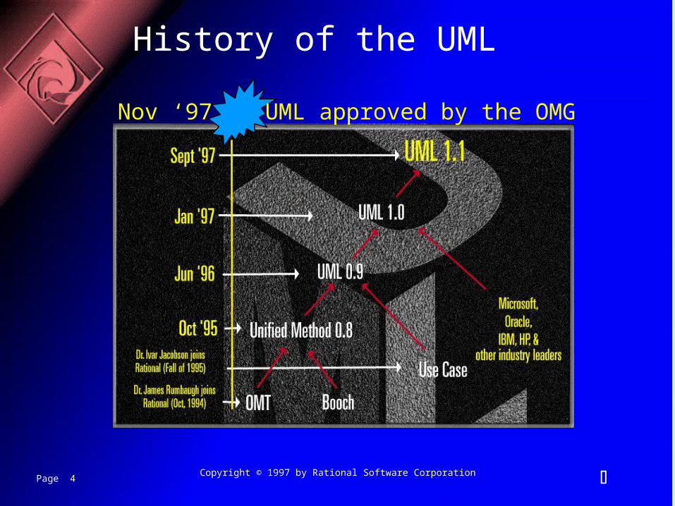
History of the UML
Nov ‘97 UML approved by the OMG
Page 5 Copyright © 1997 by Rational Software Corporation
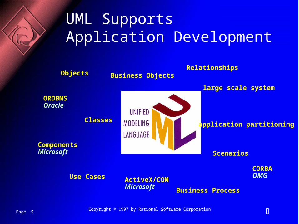
UML Supports Application Development
Classesapplication partitioning
Business ObjectsRelationships
Business Process
Objects
Use Cases
large scale system
ScenariosComponentsMicrosoft
ActiveX/COMMicrosoft
ORDBMSOracle
CORBAOMG
Page 6 Copyright © 1997 by Rational Software Corporation
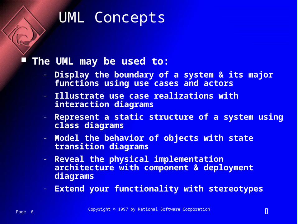
UML Concepts
The UML may be used to:– Display the boundary of a system & its major functions using use
cases and actors– Illustrate use case realizations with interaction diagrams– Represent a static structure of a system using class diagrams – Model the behavior of objects with state transition diagrams– Reveal the physical implementation architecture with component
& deployment diagrams – Extend your functionality with stereotypes
Page 7 Copyright © 1997 by Rational Software Corporation
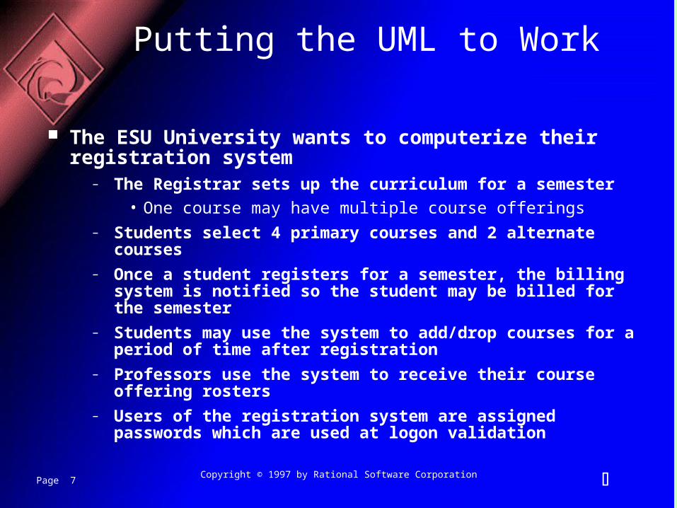
Putting the UML to Work
The ESU University wants to computerize their registration system
– The Registrar sets up the curriculum for a semester
• One course may have multiple course offerings– Students select 4 primary courses and 2 alternate courses– Once a student registers for a semester, the billing system is
notified so the student may be billed for the semester– Students may use the system to add/drop courses for a period of
time after registration– Professors use the system to receive their course offering rosters– Users of the registration system are assigned passwords which
are used at logon validation
Page 8 Copyright © 1997 by Rational Software Corporation
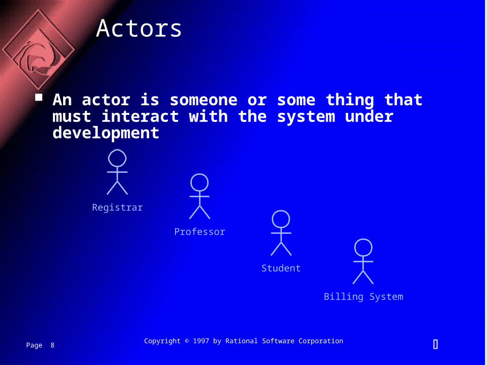
Actors
An actor is someone or some thing that must interact with the system under development
Student
Registrar
Professor
Billing System
Page 9 Copyright © 1997 by Rational Software Corporation
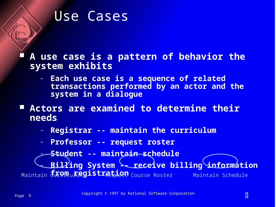
Use Cases
A use case is a pattern of behavior the system exhibits– Each use case is a sequence of related transactions performed by
an actor and the system in a dialogue
Actors are examined to determine their needs– Registrar -- maintain the curriculum– Professor -- request roster– Student -- maintain schedule– Billing System -- receive billing information from registration
Maintain ScheduleMaintain Curriculum Request Course Roster

Page 10 Copyright © 1997 by Rational Software Corporation
Documenting Use Cases
A flow of events document is created for each use cases– Written from an actor point of view
Details what the system must provide to the actor when the use cases is executed
Typical contents– How the use case starts and ends– Normal flow of events– Alternate flow of events– Exceptional flow of events
Page 11 Copyright © 1997 by Rational Software Corporation
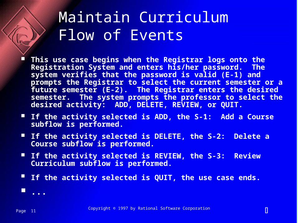
Maintain Curriculum Flow of Events
This use case begins when the Registrar logs onto the Registration System and enters his/her password. The system verifies that the password is valid (E-1) and prompts the Registrar to select the current semester or a future semester (E-2). The Registrar enters the desired semester. The system prompts the professor to select the desired activity: ADD, DELETE, REVIEW, or QUIT.
If the activity selected is ADD, the S-1: Add a Course subflow is performed.
If the activity selected is DELETE, the S-2: Delete a Course subflow is performed.
If the activity selected is REVIEW, the S-3: Review Curriculum subflow is performed.
If the activity selected is QUIT, the use case ends.
...
Page 12 Copyright © 1997 by Rational Software Corporation
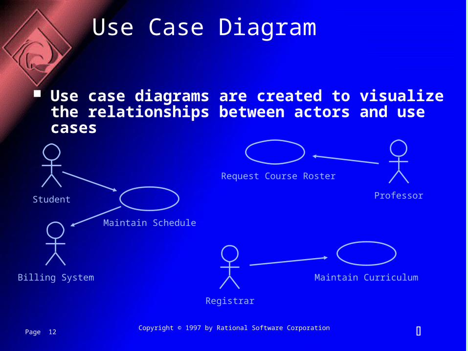
Use Case Diagram
Use case diagrams are created to visualize the relationships between actors and use cases
Student
Registrar
Professor
Maintain Schedule
Maintain Curriculum
Request Course Roster
Billing System
Page 13 Copyright © 1997 by Rational Software Corporation
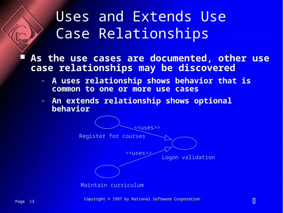
Uses and Extends Use Case Relationships
As the use cases are documented, other use case relationships may be discovered
– A uses relationship shows behavior that is common to one or more use cases
– An extends relationship shows optional behavior
Register for courses
<<uses>>
Logon validation<<uses>>
Maintain curriculum
Page 14 Copyright © 1997 by Rational Software Corporation
Use Case Realizations
The use case diagram presents an outside view of the system
Interaction diagrams describe how use cases are realized as interactions among societies of objects
Two types of interaction diagrams– Sequence diagrams– Collaboration diagrams
Page 15 Copyright © 1997 by Rational Software Corporation
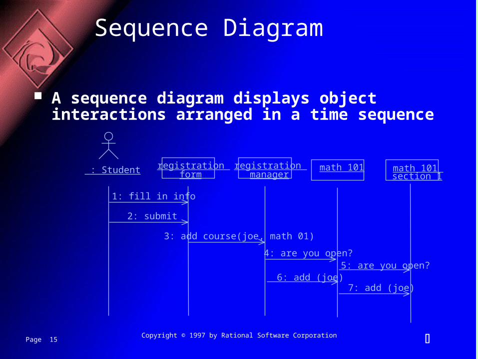
Sequence Diagram
A sequence diagram displays object interactions arranged in a time sequence
: Student registration form
registration manager
math 101
1: fill in info
2: submit
3: add course(joe, math 01)
4: are you open?5: are you open?
6: add (joe)7: add (joe)
math 101 section 1
Page 16 Copyright © 1997 by Rational Software Corporation
: Registrar
course form : CourseForm
theManager : CurriculumManager
aCourse : Course
1: set course info2: process
3: add course
4: new course
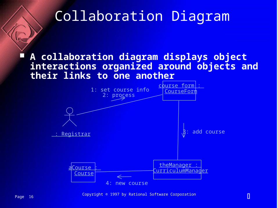
Collaboration Diagram
A collaboration diagram displays object interactions organized around objects and their links to one another
Page 17 Copyright © 1997 by Rational Software Corporation
Class Diagrams
A class diagram shows the existence of classes and their relationships in the logical view of a system
UML modeling elements in class diagrams– Classes and their structure and behavior– Association, aggregation, dependency, and inheritance
relationships– Multiplicity and navigation indicators– Role names
Page 18 Copyright © 1997 by Rational Software Corporation
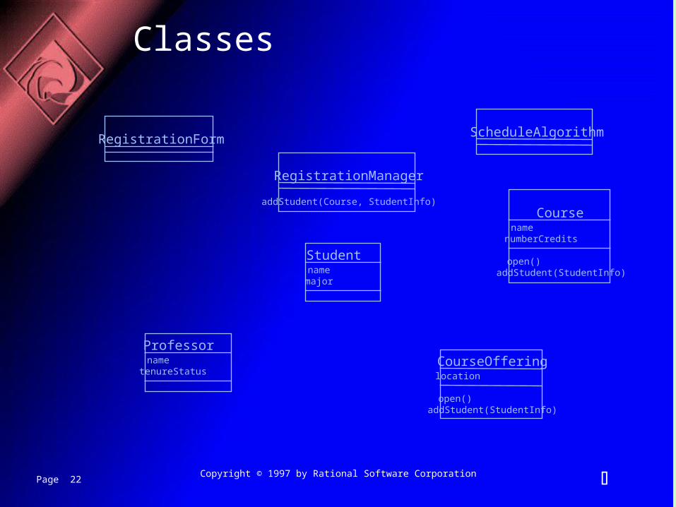
Classes
A class is a collection of objects with common structure, common behavior, common relationships and common semantics
Classes are found by examining the objects in sequence and collaboration diagram
A class is drawn as a rectangle with three compartments
Classes should be named using the vocabulary of the domain
– Naming standards should be created– e.g., all classes are singular nouns starting with a capital letter
Page 19 Copyright © 1997 by Rational Software Corporation
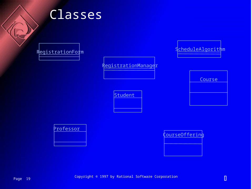
Classes
RegistrationForm
RegistrationManager
Course
Student
CourseOfferingProfessor
ScheduleAlgorithm
Page 20 Copyright © 1997 by Rational Software Corporation
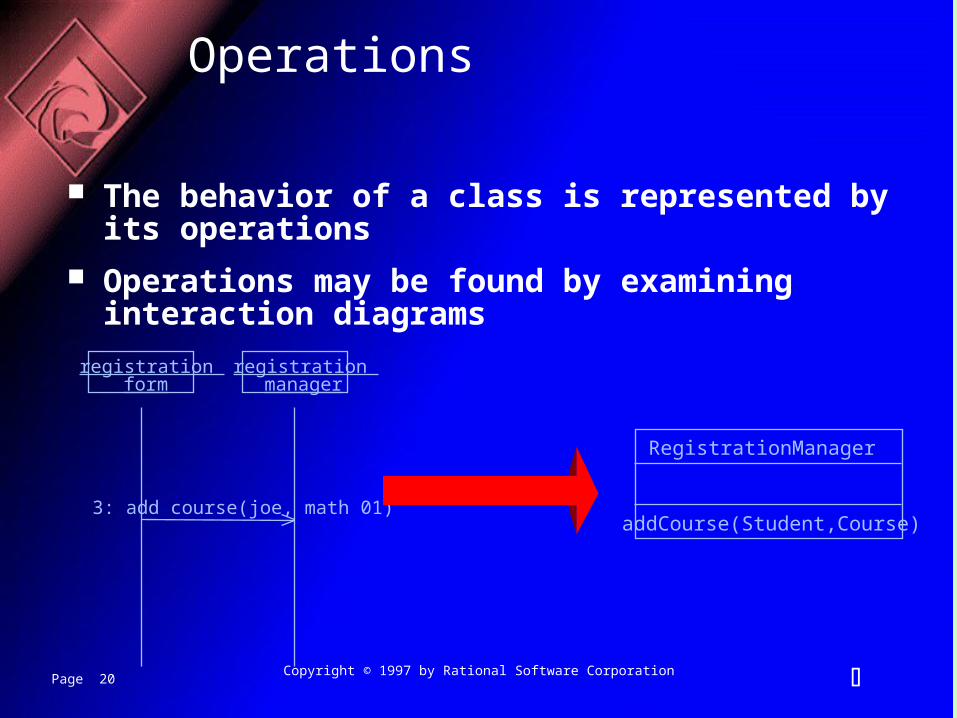
Operations
The behavior of a class is represented by its operations
Operations may be found by examining interaction diagrams
registration form
registration manager
3: add course(joe, math 01)
RegistrationManager
addCourse(Student,Course)
Page 21 Copyright © 1997 by Rational Software Corporation
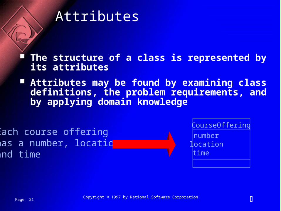
Attributes
The structure of a class is represented by its attributes
Attributes may be found by examining class definitions, the problem requirements, and by applying domain knowledge
Each course offeringhas a number, location and time
CourseOffering
numberlocationtime
Page 22 Copyright © 1997 by Rational Software Corporation
Classes
RegistrationForm
RegistrationManager
addStudent(Course, StudentInfo)Course
namenumberCredits
open()addStudent(StudentInfo)
Studentnamemajor
CourseOfferinglocation
open()addStudent(StudentInfo)
ProfessornametenureStatus
ScheduleAlgorithm
Page 23 Copyright © 1997 by Rational Software Corporation
Relationships
Relationships provide a pathway for communication between objects
Sequence and/or collaboration diagrams are examined to determine what links between objects need to exist to accomplish the behavior -- if two objects need to “talk” there must be a link between them
Three types of relationships are:– Association– Aggregation– Dependency
Page 24 Copyright © 1997 by Rational Software Corporation
Relationships
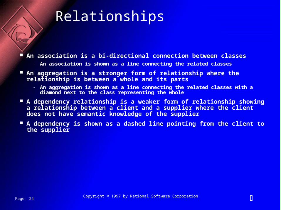
An association is a bi-directional connection between classes– An association is shown as a line connecting the related classes
An aggregation is a stronger form of relationship where the relationship is between a whole and its parts
– An aggregation is shown as a line connecting the related classes with a diamond next to the class representing the whole
A dependency relationship is a weaker form of relationship showing a relationship between a client and a supplier where the client does not have semantic knowledge of the supplier
A dependency is shown as a dashed line pointing from the client to the supplier
Page 25 Copyright © 1997 by Rational Software Corporation
Registration Manager
Math 101: Course
3: add student(joe)
RegistrationManager
Course
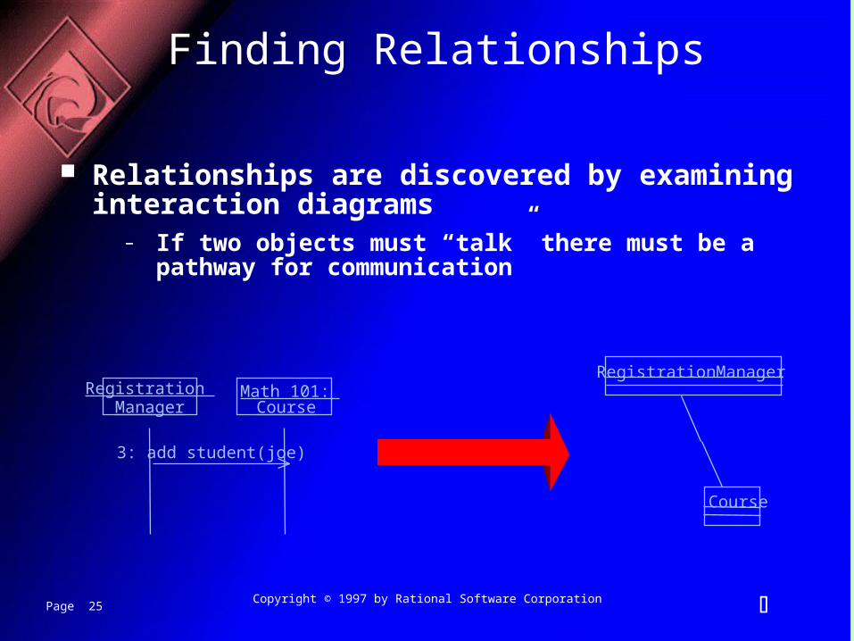
Finding Relationships
Relationships are discovered by examining interaction diagrams
– If two objects must “talk” there must be a pathway for communication
Page 26 Copyright © 1997 by Rational Software Corporation
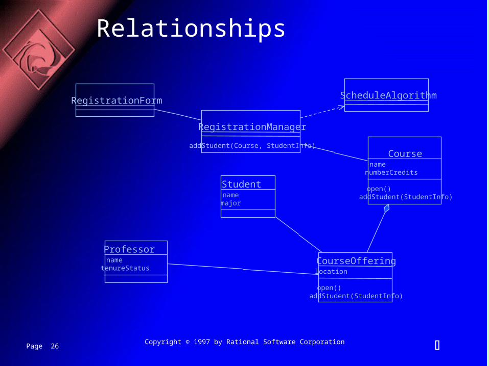
Relationships
RegistrationForm
RegistrationManager
Course
Student
CourseOfferingProfessor
addStudent(Course, StudentInfo)
namenumberCredits
open()addStudent(StudentInfo)name
major
location
open()addStudent(StudentInfo)
nametenureStatus
ScheduleAlgorithm
Page 27 Copyright © 1997 by Rational Software Corporation
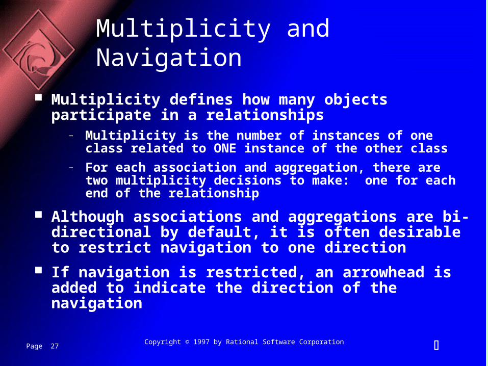
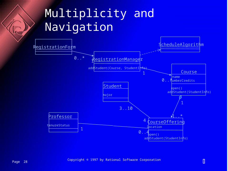
Multiplicity and Navigation
Multiplicity defines how many objects participate in a relationships
– Multiplicity is the number of instances of one class related to ONE instance of the other class
– For each association and aggregation, there are two multiplicity decisions to make: one for each end of the relationship
Although associations and aggregations are bi-directional by default, it is often desirable to restrict navigation to one direction
If navigation is restricted, an arrowhead is added to indicate the direction of the navigation
Page 28 Copyright © 1997 by Rational Software Corporation
Multiplicity and Navigation
RegistrationForm
RegistrationManager
Course
Student
CourseOfferingProfessor
addStudent(Course, StudentInfo)
namenumberCredits
open()addStudent(StudentInfo)
major
location
open()addStudent(StudentInfo)
tenureStatus
ScheduleAlgorithm
10..*
0..*
1
1
1..*4
3..10
0..41
Page 29 Copyright © 1997 by Rational Software Corporation
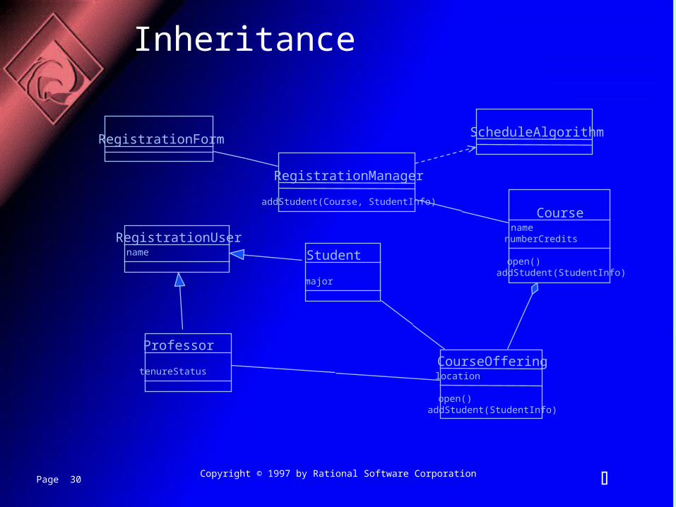
Inheritance
Inheritance is a relationships between a superclass and its subclasses
There are two ways to find inheritance:– Generalization– Specialization
Common attributes, operations, and/or relationships are shown at the highest applicable level in the hierarchy
Page 30 Copyright © 1997 by Rational Software Corporation
Inheritance
RegistrationForm
RegistrationManager
Course
Student
CourseOfferingProfessor
addStudent(Course, StudentInfo)
namenumberCredits
open()addStudent(StudentInfo)
major
location
open()addStudent(StudentInfo)
tenureStatus
ScheduleAlgorithm
name
RegistrationUser
Page 31 Copyright © 1997 by Rational Software Corporation
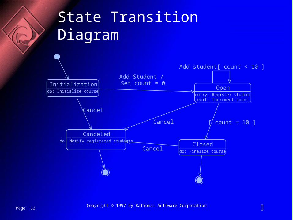
The State of an Object
A state transition diagram shows – The life history of a given class– The events that cause a transition from one state to another– The actions that result from a state change
State transition diagrams are created for objects with significant dynamic behavior
Page 32 Copyright © 1997 by Rational Software Corporation
State Transition Diagram
InitializationOpen
entry: Register studentexit: Increment count
Closed
Canceled
do: Initialize course
do: Finalize course
do: Notify registered students
Add Student / Set count = 0
Add student[ count < 10 ]
[ count = 10 ]
Cancel
Cancel
Cancel
Page 33 Copyright © 1997 by Rational Software Corporation
The Physical World
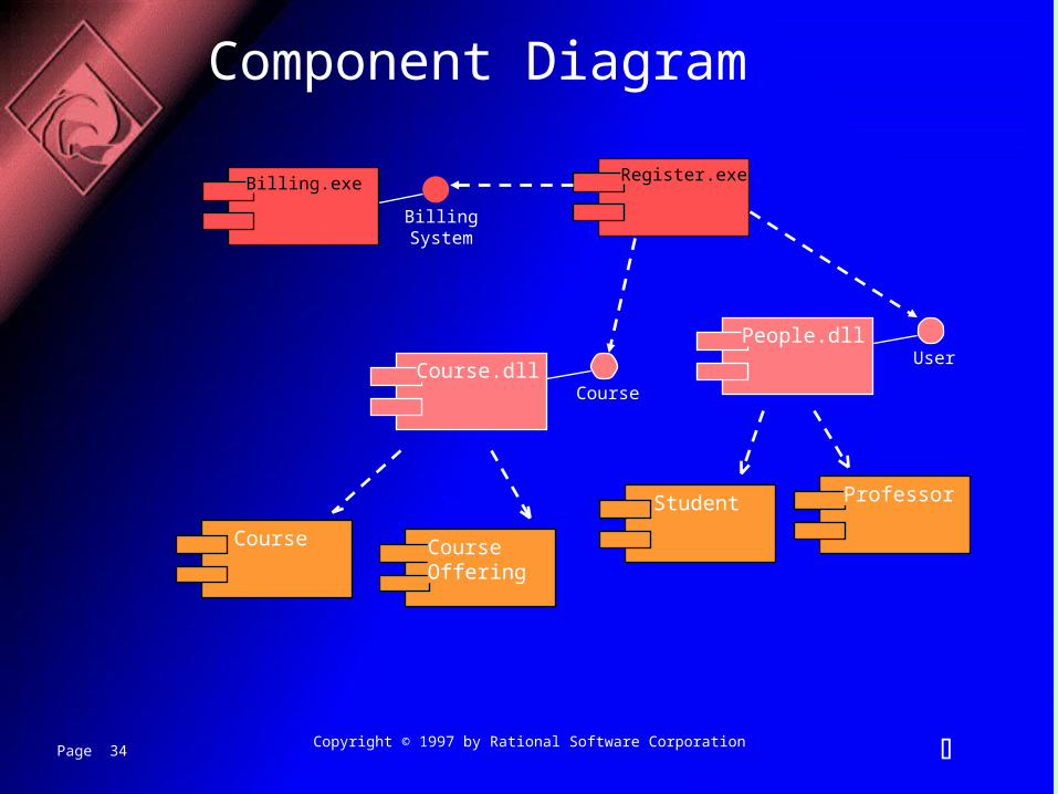
Component diagrams illustrate the organizations and dependencies among software components
A component may be – A source code component– A run time components or– An executable component
Page 34 Copyright © 1997 by Rational Software Corporation
Course CourseOffering
Student Professor
Component Diagram
Course.dll
People.dll
Course
User
Register.exeBilling.exe
BillingSystem
Page 35 Copyright © 1997 by Rational Software Corporation
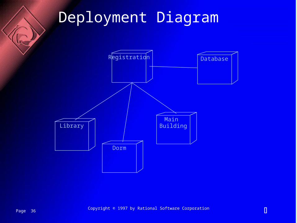
Deploying the System
The deployment diagram shows the configuration of run-time processing elements and the software processes living on them
The deployment diagram visualizes the distribution of components across the enterprise.
Page 36 Copyright © 1997 by Rational Software Corporation
Deployment Diagram
Registration Database
Library
Dorm
Main Building


![6. UML Class Diagrams 6-1 Part 6: UML Class Diagramsusers.informatik.uni-halle.de/~brass/dd04/c6_umlcl.pdf · the artifacts of a software system. ... [Rational Software Corporation]](https://static.documents.pub/doc/80x56/5b146d657f8b9a257c8d1ccb/6-uml-class-diagrams-6-1-part-6-uml-class-brassdd04c6umlclpdf-the-artifacts.jpg)


