Disclaimer: The editorial content published in this newsletter is the sole responsibility of the authors. The Injection Molding Division publishes this content for the use and benefit of its members, but is not responsible for the accuracy or validity of editorial content contributed by various sources. Feature Page 13 Spring 2011 Chair’s Message Greetings! April 2012 was certainly a busy month for the Injection Molding Division (IMD). Many of us participated in the first-ever and very successful NPE 2012 in Orlando, FL. Co-located with ANTEC 2012, our division had three full days of ANTEC sessions highlighting new technolo- gies in the areas of materials, tooling, processing and simulation. On behalf of the IMD, we would like to express our sincere thanks to ANTEC 2012 IMD Technical Program Chair, Erik Foltz. Erik did an outstanding job in organiz- ing the technical sessions. Thanks to Erik Foltz and Jack Dispenza for their efforts in organizing our IMD Reception held on Tuesday evening, April 3. We would like to add that the IMD received the Pinnacle Gold Award from SPE. I accepted the award on behalf of our division at the SPE Luncheon on Sunday, April 1. Our focus continues to be technical programming and education for our membership. Pete Grelle, Technical Director, is working with Barbara Spain from SPE to schedule Injection Molding webinars for 2012-2013. Some of the topics suggested to us have been as follows: In This Issue: Letter from the Chair ........................................... 1 Industry Events...................................................... 2 In Memory of Donald Allen .............................. 3 Ask The Expert: Injection Molding ................ 4 Ask the Expert: Hot Runners ........................... 6 Ask the Expert: Mold Maintenance .............. 9 Ask the Expert: CAE ........................................ 14 This Month’s Features: Using Design of Experiments for ............ 18 Optimizing Injection Molding | Carsten Lund IMD Best Paper: Troubleshooting Black Specs .................. 24 and Color Streaks in Injection Molded Parts | Mark A. Spalding and Gregory A. Campbell IMD Board Minutes .......................................... 34 Stout Foundation ............................................. 39 IMD Leadership ................................................. 40 New IMD Members .......................................... 41 Membership Application............................... 45 Sponsors in this Issue ...................................... 46 Publisher’s Message ........................................ 46 Sponsorship Opportunites ........................... 46
Transcript
Disclaimer: The editorial content published in this newsletter is the sole responsibility of the authors. The Injection Molding Division publishes this content for the use and benefit of its members, but is not responsible for the accuracy or validity of editorial content contributed by various sources.
Feature
Page 13 Spring 2011
Chair’s Message
Greetings!
April 2012 was certainly a busy month for the Injection Molding Division (IMD). Many of us participated in the first-ever and very successful NPE 2012 in Orlando, FL. Co-located with ANTEC 2012, our division had three full days of ANTEC sessions highlighting new technolo-gies in the areas of materials, tooling, processing and simulation. On behalf of the IMD, we would like to express our sincere thanks to ANTEC 2012 IMD Technical Program Chair, Erik Foltz. Erik did an outstanding job in organiz-ing the technical sessions. Thanks to Erik Foltz and Jack Dispenza for their efforts in organizing our IMD Reception held on Tuesday evening, April 3. We would like to add that the IMD received the Pinnacle Gold Award from SPE. I accepted the award on behalf of our division at the SPE Luncheon on Sunday, April 1.
Our focus continues to be technical programming and education for our membership. Pete Grelle, Technical Director, is working with Barbara Spain from SPE to schedule Injection Molding webinars for 2012-2013. Some of the topics suggested to us have been as follows:
In This Issue:Letter from the Chair ...........................................1
Industry Events ......................................................2
In Memory of Donald Allen ..............................3
Ask The Expert: Injection Molding ................4
Ask the Expert: Hot Runners ...........................6
Ask the Expert: Mold Maintenance ..............9
Ask the Expert: CAE ........................................14
This Month’s Features:Using Design of Experiments for ............18Optimizing Injection Molding | Carsten Lund
IMD Best Paper: Troubleshooting Black Specs ..................24and Color Streaks in Injection Molded Parts | Mark A. Spalding and Gregory A. Campbell
Injection Molding Basic Principles, Troubleshooting, Mold Maintenance, Design of Experiments, Process Control, Injection Molding Part Design Basics and Advanced Injection Molding. The board would greatly ap-preciate your feedback as to which topics would be of interest to your teams. Please contact me with any suggestions at [email protected] and I will pass them on to Pete and our IMD Board of Directors at our next meeting.
The IMD is already “gearing up” for ANTEC 2013 to be held April 22-24, 2013 in Cincinnati, OH. We encourage those of you with interesting topics or research to submit your papers. Remember that your topical contributions are what makes for great technical sessions. The dead-line for ANTEC 2013 papers is October 23, 2012 at 5PM. For more infor-mation, go to http://www.4spe.org/conferences-and-events and click on ANTEC 2013.
Thank you for your participation in SPE and your continued support of the IMD.
Best regards,Susan Montgomery
Chair, IMD Board of Directors
September 201210-15: IMTS 2012
Chicago, IL http://www.imts.com
11-13: AUTOMOTIVE COMPOSITES CONFERENCE &
EXHIBITION® 2012
Troy, MI, GA http://speautomotive.com/comp.htm
22-25: THERMOFORMING 2012 CONFERENCE®
Grand Rapids, MI, GA http://www.4spe.org/conferences-and-events
October 20121-2: CAD RETEC® 2012 CONFERENCE-
50 YEARS OF COLORING PLASTICS
Johannesburg, South Africa http://www.4spe.org/conferences-and-events
Industry Events CalendarClick the show links for more information on these events!
SPE Injection Molding Division www.4spe.org
In Memory of Donald Allen
Page 3 Summer 2012
SPE in Memory of Donald Allen (1945-2012)
Former IMD Board Member Don Allen passed away in early March, leaving his wife
Nance (Hobokan) and family, as well as a host of plastics industry friends and former ChevronPhillips co-workers.
Don worked in the plastics industry for nearly 50 years, starting at Continental Plastics in 1961, then moving onto a variety of roles at Steel Specialties, Sewell Plastics, Hoover Universal, Universal Plastic Mold, and then to Phillips Petroleum in 1989 until his retirement from ChevronPhillips in 2009. Along the way, Don was awarded 5 patents, authored more than 20 technical papers, and helped countless customers solve their molding issues.
He was a devoted SPE Injection Molding Division member and volunteer—IMD Board of Directors Chairman, Engineer of the Year (2007), ANTEC Technical Program Chairperson (1999), and a Certified Plastics Technologist (though Don also called himself “certifiable” under certain conditions).
For many years, Don somehow made time to be an invaluable part of every ANTEC paper review imag-inable, poring over the details and feasibility of injection molding developments and data. He was a key developer of the IMD’s Molders Clinic panel sessions at ANTEC as well.
Don once told us told us that he had seen nearly everything one could imagine on molding floors, none of which really surprised him and most of which he declined to detail—always with a sly smile. Many of us know that he could make plastics do just about anything, and he shared his ideas with customers, col-leagues, and friends. In his spare time, he showed a similar passion for drag racing and fast cars.
Don, thank you for your service, friend.
Charitable donations in memory of Don Allen can be made to “Bicycles for Pastors in Restricted Nations” to The Voice of the Martyrs, Box 443, Bartlesville, OK 74005.
SPE Injection Molding Division www.4spe.org
Feature
Page 4 Summer 2012
Ask the Experts: Bob Dealy
Are there any rules of thumb concerning what is the first material that should be injected when designing a part for two shot molding? I want to design a number of keys where they will have two sets of marking, one on the top and the other on a side. I’m debating if it would be best to first mold the main part of the button with voids for the wording and then use the second shot to fill in the cavity, or is it better to over mold the body with the letters standing and last material covering just the body.
I’m not sure there are rules of thumb concerning your question related to two shot (two color) molding. What I do know is that when you have two materials with
different melt temperatures, you mold the highest melt temperature first.Also, when two different plastic materials of different hardness are utilized, the preferred
method is to mold the harder material first and over mold the softer materials. When the same material is used to make a two color molded part the factors to consider are: what is the lowest part cost; cost of the mold, considering both the initial cost; and maintaining the mold over its life.
For example, in the case of a push button where the same material will be used to mold both the body and only a differ-ent color for the over molded part like the following examples. The are two advantages when the main body is molded first. One is that the mold while requiring a slide for the side letter-ing, is more robust for molding a standing letter than a mold with an opening creating an opening for receiving the second color. The second is should the part have any sink marks from a thicker section, the second color will cover that defect. See example 1, for the first shot molded component body.
When the second color is over molded, the blue color in our example, the button body will be encased in a solid cavity and the second material molded over the body. The lettering will retain the color of the first plastic and show in contrast with the second color. See example 2 for the two colored component.
Injection Molding QuestionsMaterials
Q:
A:
Bob Dealey, owner and president of Dealey’s Mold Engineering, Inc. answers your questions about injection molding.
Bob has over 30 years of experience in plastics injection-molding design,tooling, and processing.
While this method results in a high quality key that will retain it marking for life, other options could be considered for reducing costs. The keyboard I’m working on would require a dedicated first cavity for each button with 92 cavities. A second mold with the same number of cavities, in the same layout is necessary for an automated two shot molding operation. My calculator requires 33 different cavities and some are different shapes, plus the second mold. Therefore, tooling costs can be high.
Pad printing or hot stamping might be considered. The buttons can be molded in a conventional injection molding machine in just one mold. The buttons can then be printed as desired. In the 1970’s the automotive industry was so concerned that the lettering could wear off printed dash buttons that paint filling was the only accepted method of marking. This was a tedious and expensive decoration method. Today, I note that my car has pad printed markings. In addition to being more cost effective, the appearance is much better and I believe they will out last the life of my car.
The tooling costs are easier to control. If all the buttons are of the same shape, low volume requirements can be met with lower number of cavities. Large volume applications can have high cavitation to reduce the molded part cost. Additionally, buttons with different color combinations, both molded and printed, are more cost effective and convenient to manufacture.
As always, if any of our readers know of any rules of thumb or can offer additional advice, please write me at [email protected] always, comments from the readers are welcome and can be sent to: Bob Dealey, [email protected]
Bob Dealy Dealy’s Mold Engineering
Ask the Experts: Terry L. Schwenk
SPE Injection Molding Division www.4spe.org
Page 6 Summer 2012
Hot Runner Tips
How do you know what the correct gate size is for a hot tip system?
Making sure your application has a correct gate size from the get go, can be a daunting task for sure. Too big a gate means you will be weld-ing up steel and re-cutting the gate. Too small of a gate, you will have to
open up or sacrifice the process. When selecting a gate size for an application, never select the gate size strictly on vestige requirements. You will always be disappoint-ed with the outcome. If gate vestige is an issue, then the application must be valve gated, “period“. Hot Tip gates should be sized to allow for moderate fill and packing condition to produce acceptable part quality. So how can we determine what size gate will produce acceptable part quality.
When selecting a gate size, there are an abundance of tools from using gate standards to mold flow. No matter what approach you take always use scientific methods approach to gate sizing. So what are the factors that affect the process in selecting a gate size for hot tip hot runner systems? Typical gate sizes can range from .024 inch (.6mm) to .070 inch (1.8mm) Here are the list of factors I use in selecting a gate size.
The purpose of this column is to provide valid information concerning hot runner technology. We invite you to submit questions or comments to our hot runner expert, Terry L. Schwenk has over 35 years of processing and hot runner experience. Terry is currently employ-ed with EWIKON Molding Technologies and can be reached by mailing:terry.schwenk@ ewikonusa.com.
Q:
A:
Material structure can be amorphous, semi-crystalline or crystalline. Knowing this relates to how quickly a gate will freeze off. Amorphous materials taking longer to solidify then crystalline materials thus requiring smaller gate sizes.
Molecular weight will affect the flow characteristics of the material. Higher weight will require a larger gate.Melt Flow Index reflects on viscosity of the resin and how it flows at slow rates and really only has a bearing
on the initial fill when the gate opens. A lower melt flow index will require a slightly larger gate.Fillers depending on the type, either take up space or can cause the material to solidify quickly requiring
larger gates sizes. Additives such as flame retardants and colorants will require larger gate sizes.Shear sensitive materials will require larger gates.How quickly the material solidifies will determine the gate size. Material that solidifies quickly will require
a larger gate size, especially if you require a longer pack time, in order to keep the gate open for the packing pressures to have any effect.
Part weight or volume should be sized accordingly; smaller parts can have smaller gates larger parts can have larger gates.
Ask the Experts: Terry L. Schwenk Continued
SPE Injection Molding Division www.4spe.org
Page 7 Summer 2012
SPE Injection Molding Division www.4spe.org
Ask the Experts: Terry L. Schwenk Continued
Page 8 Summer 2012
Wall section is another factor to consider. When gating into a thin wall section you can get by with a smaller gate because a thin wall section will freeze faster. Thick wall sections require a larger gate size in order for the gate to stay open for longer period of time.
Part dimension or tolerances will also determine the gate size. The tighter the part tolerances the larger the gate required to pack the part more consistently.
The end use of the part, whether technical or cosmetic will have a bearing on the gate size.Vestige requirements plays a part in gate size, but again I stress it is low on the list and again I reiterate, if
vestige will be an issue then valve gate the part. Another aspect that plays a part is gate strings. Fast cycles and stringing material require valve gates.
Temperature window refers to the processing temperature range of the material being processed. Some materials have a wider temperature range then others and will require a smaller gate size.
Fast injection speeds generally require larger gates, however there are some exceptions whereby you may want a smaller gate to induce additional shear reducing melt viscosity, thus gaining flow length of the material.
Pressure drop in the part and hot runner system will help determining gate size. Larger pressure drop requires a larger gate.
The effect of holding pressure, more holding pressure requires a larger gate.As you can see most of the factors are common sense. However having a good understanding of the
injection molding process along with knowing material characteristics go a long way in predicting the perfect gate size for your application.
I have designed a spreadsheet I use to determined gate sizes, based on all the criteria discussed above. You choose each criteria and it automatically determines the gate size.
For those who wish to have this chart, I will supply free of charge. Just e-mail me your contact
information and I will send the program. I only require to be held harmless from any use of the chart.
Terry L. Schwenk EWIKON Molding Technologies
If you have a question or tip HOT RUNNERS?E-mail Terry Schwenk at [email protected]
Please submit any questions or comments to maintenance expert Steve Johnson, Operations Manager for ToolingDocs LLC, and owner of MoldTrax.
Steve has worked in this industry for more than 32 years. E-mail Steve at [email protected] or call (419) 281-0790.
Just because the mold started back up and ran at 100% efficiency, does that mean that the repair was efficient or that the tooling replaced was really at the end of its “useful life”? What is “useful life” and how can we tell?
To better understand the corrective action choices that a mold repair technician faces every day, it is necessary to look at the decision pro-cess typically used to determine what tooling to replace – or not.
Typical Troubleshooting ProcessThere are basically two categories of defects that repair technicians have to
contend with. They are mold function issues that don’t directly affect the plastic part, and tooling issues that mold or form different geometries on a part. For this article we will focus on the latter: “product” type defects, or those that affect product specifications such as flash, shorts, finish, etc.
Note that for this repair scenario we will assume that the repair technician has, according to the hand written Work Order he received, disassembled the multi-cavity mold and marked up a cavity layout sheet that shows the location of the cavities that have flash over the specification limit.
Next Steps:1. Examine the sample part defect samples to determine the exact location
of the flash on the part.2. Determine exactly which pieces of tooling could be causing the flash (core,
sleeve, cavity, etc.).3. Remove and examine the tooling in the area that forms the flashed area of
the part.4. If nothing is obvious (chips, nicks, scuffs, etc.), go to the tool crib and pull
drawers until you find the tooling you need.5. Measure the tooling and compare to print tolerances. If under print specifi-
cations, replace. (This is optional for some and mandatory for others.)6. Install the tooling in the mold and complete the repair.
Q:
A:
SPE Injection Molding Division www.4spe.org
Ask the Experts: Steve Johnson Continued
Page 10 Summer 2012
The above steps are what could be expected of a “tooling replacer” vs. a skilled troubleshooter. There are several things the replacer does not do within these steps to insure the decision to replace is the correct one to make.
Effective TroubleshootingNow let’s re-examine these steps from a “troubleshooter’s” perspective to see what was missed and why
those missed steps are critical to maximizing the life expectancy of mold tooling, the reliability mold perfor-mance and also to improve our ability to accurately determine root causes and corrective actions.
1. Examine the sample part defects to determine the exact location of the flash on the part.
It’s more than just “location” of the flash on the part that must be considered (processors take note: This is why samples of defective parts are so important!). The “direction” of the flash must also be known. For ex-ample, “vertical” flash is usually the result of an excess of plastic between a core and a sleeve or any tooling where clearance is determined by a running fit. “Horizontal” flash is usually the result of an excess of plastic between two shutoffs, such as “A” and “B” plate cavity faces or tooling where “preload” (total tooling stack) or
SPE Injection Molding Division www.4spe.org
Ask the Experts: Steve Johnson Continued
Page 11 Summer 2012
clamp pressure and other “shut-off” factors affect clearance. Sometimes it’s also helpful to know the thickness of the flash. Regardless, these two types of flash must
be distinguished by an appropriate defect term because their root cause – thus corrective action – could be completely unrelated.
This is a good example of why typical Work Order records that show only the defect term “flash” won’t do. Mold design features that cause ongoing flash issues must be recognized in order to be eliminated or reduced when the next mold is built. When repair techs are pushed to get a mold back into the press, sometimes “shop culture” will allow this tooling to be replaced just because it’s in stock. No big deal, right? Yes, it is. Premature replacement causes us to miss the opportunity to understand and define the variables that actually create our defects. This is a skill that needs to be continually developed because continuous improvement is about improving our ability to accurately determine if any given defect is caused by a mold design, process, mainte-nance issue or a unique combination of all three.
2. Determine exactly which pieces of tooling could be causing the flash (core, sleeve, cavity, etc.)
The more complex the part, and the more difficult to eject from the mold due to threads, undercuts, bores, bosses, etc., typically means more tooling is needed to shape the part. A mold could easily have 3, 4 or more pieces of tooling molding an edge or other feature on a part. But not all of these will be worn to the point of causing the flash. Some mold design-ers take this into consideration when design-ing a mold and will have less expensive pieces designed to wear first, or most often, to lessen the cost of repair. Maintenance history will confirm or deny success.
All defects should also be recorded and tracked by mold position so that one can look for patterns or trends that can point to insuf-ficient cooling, heating, runner/flow balance, gate and venting issues and other process-related root causes.
Not doing so is a huge mistake and can really lengthen the time required to discover a root cause. Mold tooling develops a “running fit” or seat over time. To ensure that these compo-nents get put back into their “home” positions after every repair, tooling position numbers should be stamped, etched or ground into all plates and tooling.
SPE Injection Molding Division www.4spe.org
Ask the Experts: Steve Johnson Continued
Page 12 Summer 2012
3. Remove and examine the tooling that forms the flashed area of the part
Here is another area where the troubleshooter is differentiated from a tooling replacer.First, if two or more parts (positions) have the exact same defect, it always pays to examine the tooling all at
the same time vs. skipping around the mold in say a clockwise fashion (many do this) analyzing and correct-ing different defects as you go.
Second, don’t just grab your micrometers, measure the tooling and assume that it’s bad if under print di-mensions. There are hundreds of thousands of tooling components that make perfectly acceptable (within Q/A specifications) parts and are .001, .002, or .003 under print tolerances. Print tolerances should be a factor in replacement decisions – not the decider.
Third, develop a standard method to examine tooling such as the following:1. Remove the suspect tooling from the mold and make sure all pieces are numbered correctly to their home
position.2. Go to the tool crib and get one piece of new/replacement tooling that matches what you removed3. Grab the defective parts, old tooling, new tooling and head to your good quality stereo microscope.4. Orient the tooling in the manner the tooling fits together in the mold5. Set the power on the scope to 10 for most parts unless you micro-mold, then higher power is needed. Why
10 power? Typically you will be looking for clearances between tooling fits that ranges from .0005 to .005. A .001 gap between tooling looks like the Grand Canyon at anything much over 10p which can make a good running fit appear as it should be flashing. Stay with 10p as much as possible in everything you do and you will get very good at accurately judging good running fits vs. those with too much clearance. Be consistent in your microscope practices and you will soon recognize the difference between tooling fits with acceptable clearance and those that are not. Well equipped shops have scopes for each repair technician.
6. Compare the mated tooling to the area of flash on the part, being aware of flash direction, length and thickness. After you have found the area of the tooling that is flashing, make a mental note of the clearance between the tooling. Now replace one of the suspect tooling components with a new piece and re-examine the clearance. Does it looks smaller or stay the same? If it’s a dynamic fit, (core vs. sleeve) does it feel the same? Tighter? Still loose?
7. Interchange new tooling with old (this takes only a few minutes) to determine which piece of tooling has the most influence on increasing the clearance between the two or more pieces of tooling that form the flashed area.
8. Continue with this method until you have chosen which tooling you want to replace on all similar defects. The above method should not take longer than a few minutes per defect to accurately determine what
needs to be replaced. Even if troubleshooting 10 defects took an extra hour or two, it would be much more cost effective to spend the time on labor vs. the extra thousands of dollars you will spend on tooling replacing it before its useful life has expired, plus we will learn more about our mold’s defects.
4. Install the tooling and document the repair
1. When satisfied, inscribe (using a small Dremel grinder and stone) the position number onto the tooling you want to replace. This will help avoid any mix-ups in future repairs. Be sure to document in your mainte-nance system exactly which piece of tooling you replaced to repair which defect. This is necessary to allow a “Corrective Action Analysis” report to discover and target high cost defects.
This is also needed so repair technicians can get better at “forecasting” tooling wear over time, and to verify that the correct piece of tooling was chosen for replacement. No, the right choice will not always be made
SPE Injection Molding Division www.4spe.org
Ask the Experts: Steve Johnson Continued
Page 13 Summer 2012
the first time, and there will be times when it is absolutely necessary to replace everything in sight to ensure a mold runs 100% for long production runs (months), but one will still have an opportunity to save one’s com-pany thousands of dollars in premature tooling replacement by using the above techniques vs. “just replace everything” as a corrective action resolution.
This is the true skill in troubleshooting. A repair technician that practices this technique will get very good at determining which piece of tooling to replace vs. replacing everything that could possibly cause the flash. Anybody can be a “replacer”. To be a skilled troubleshooter it’s about understanding how your molds function, running characteristics, paying attention to the details, establishing a consistent troubleshooting method and using historical data collected to guide your tooling replacement decisions.
If you have a question on MOLD MAINTENCE?E-mail Steve Johnson at [email protected]
SPE Injection Molding Division www.4spe.org
Feature
Page 14 Summer 2012
FeatureAsk the Experts: CAE
Often when performing a CAE flow analysis, the material I am using is not listed in the material database. What are the steps needed to be taken to get a material into the database? Are there other alternatives?
The accuracy of a CAE mold filling analysis is highly dependent on the quality of the melt characterization and the associated characterization files. The old adage “garbage in – garbage out” — clearly applies here. Unfortunately as you are experiencing, these characterization files may not
always be readily available in your software package of choice. For example, a custom compounded material will most likely not be characterized.
One solution is to contact the material supplier’s technical support team and request a characterization file for the specific material. The material supplier may have an FTP site where these files are available for down-load, or the supplier could send them directly via e-mail. From there, you can either import this file into your simulation software, or you can modify the format to accommodate the program you are using. Once this is
done, your simulation will be ready to run. This is the sim-plest and most cost-effective means of acquiring a material characterization file.
If the material supplier does not have the specific material characterized, there are other options. You could ask the material supplier to charac-terize the material for you. But the fact of the matter is, de-pending on how much mate-rial you or the industry is buy-ing, the supplier simply may not be willing to make that investment. So, in that case, the material supplier may rec-ommend an “equivalent” ma-terial with similar properties, which may already be charac-
CAE
Q:
A:
������������ � � ������ �����
����� �����������
����� �������� ���
����������� ������������������ ��
�������� ����� �������
SPE Injection Molding Division www.4spe.org
Feature
Page 15 Summer 2012
Ask the Experts: CAE Continued
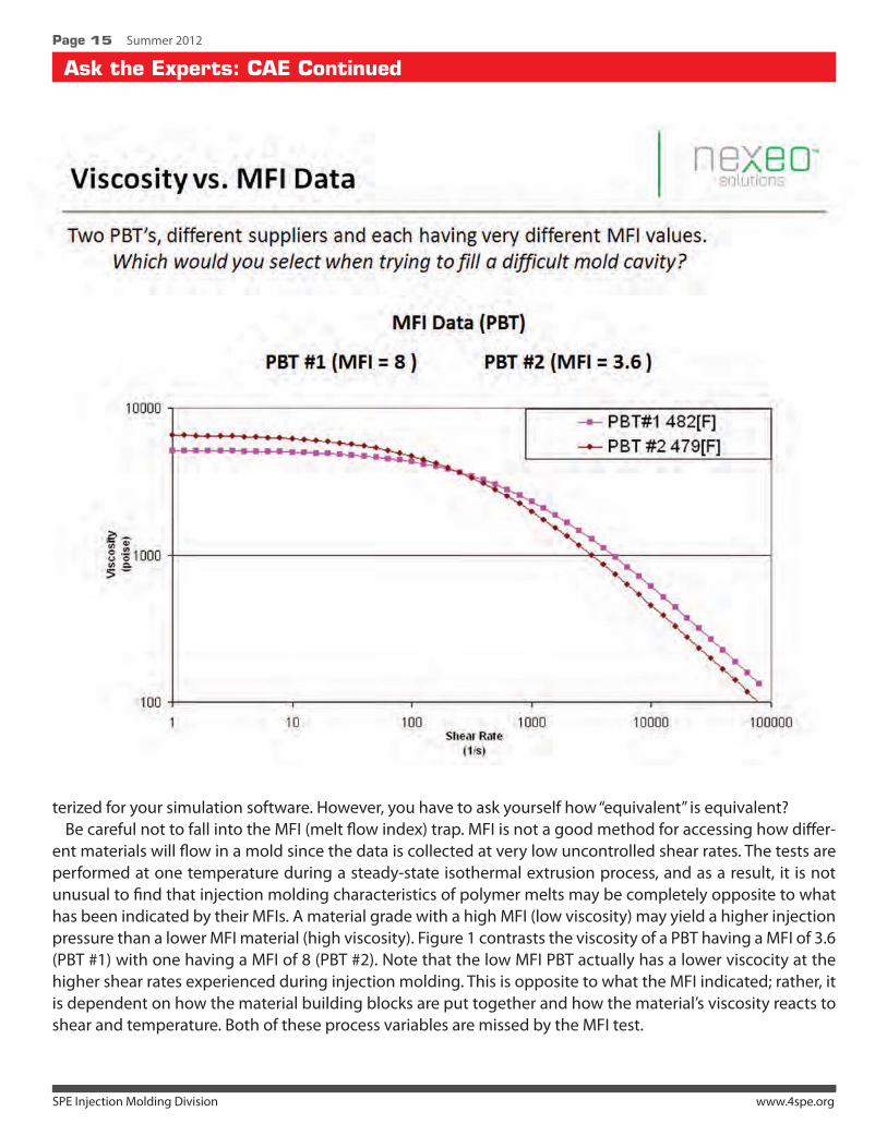
terized for your simulation software. However, you have to ask yourself how “equivalent” is equivalent? Be careful not to fall into the MFI (melt flow index) trap. MFI is not a good method for accessing how differ-
ent materials will flow in a mold since the data is collected at very low uncontrolled shear rates. The tests are performed at one temperature during a steady-state isothermal extrusion process, and as a result, it is not unusual to find that injection molding characteristics of polymer melts may be completely opposite to what has been indicated by their MFIs. A material grade with a high MFI (low viscosity) may yield a higher injection pressure than a lower MFI material (high viscosity). Figure 1 contrasts the viscosity of a PBT having a MFI of 3.6 (PBT #1) with one having a MFI of 8 (PBT #2). Note that the low MFI PBT actually has a lower viscocity at the higher shear rates experienced during injection molding. This is opposite to what the MFI indicated; rather, it is dependent on how the material building blocks are put together and how the material’s viscosity reacts to shear and temperature. Both of these process variables are missed by the MFI test.
SPE Injection Molding Division www.4spe.org
Feature
Page 16 Summer 2012
Ask the Experts: CAE Continued
If the material supplier turns out to be of no help, there are other options. Independent testing laboratories are available to test your material and develop the data needed for flow simulation. The material is character-ized with a capillary rheometer to generate viscosity versus shear rate curves at multiple temperatures. Tested shear rates may range from 1 up to 100,000 1/s or more. Other material data typically included in the test-ing is PvT, melt density, thermal conductivity, specific heat and melt-to-solid phase transition temperatures. The various commercial programs may recommend characterizations that complement their programs. For example, Autodesk Moldflow recommends corrected residual in-mold stress (CRIMS) testing to improve its shrinkage and warpage predictions for midplane meshes. Having your material fully characterized will add cost to your project, but it will provide much more reliable simulation results as compared to using an alter-nate material with a similar MFI. Also, if you are having your material characterized, it is highly recommended that you contract a company that has extensive experience characterizing materials for injection molding simulation programs.
If all else fails, you can scour the multitude of online material databases, such as IDES and Matweb for a simi-lar material. Key properties to look for include the material’s melt flow index (if capillary rheometer data is not available), viscosity index, transition temperatures, processing temperatures, density, filler type and content. The more properties that are similar to the required material, the more reliable the final result will be. Remem-
SPE Injection Molding Division www.4spe.org
Feature
Page 17 Summer 2012
Ask the Experts: CAE Continued
ber, this approach of using substitute materials, with apparently similar properties, carries a high degree of risk. Also, when using any characterization file, it is important to evaluate all data points and check to see if any supplemental (generic) data has been utilized. Any generic values that do not correlate to your specific material’s properties can interfere with developing accurate results. Supplemental data can include, but not be limited to, a material’s mechanical or PvT properties. If generic data is used for these values, the accuracy of your results could be jeopardized.
Even with a fully-characterized material in the database, the analysis can still provide inaccurate results. As stated earlier, standard industry material characterization techniques do not replicate the cyclic non-isother-mal conditions of injection molding that includes extremely high thermal exchange rates and material phase changes. Viscosity is captured by rheometers that are isothermal extrusion-based tests. Frozen layer thick-nesses are developed at cooling rates that can be hundreds of degrees per second. There is no test method that can capture this fluid-to-solid phase change at these cooling rates. The resultant differences in current testing techniques versus actual molding conditions, coupled with the inherent error expected when trying to mathematically model polymer properties and the injection molding process, will result in some degree of error in injection mold filling simulations.
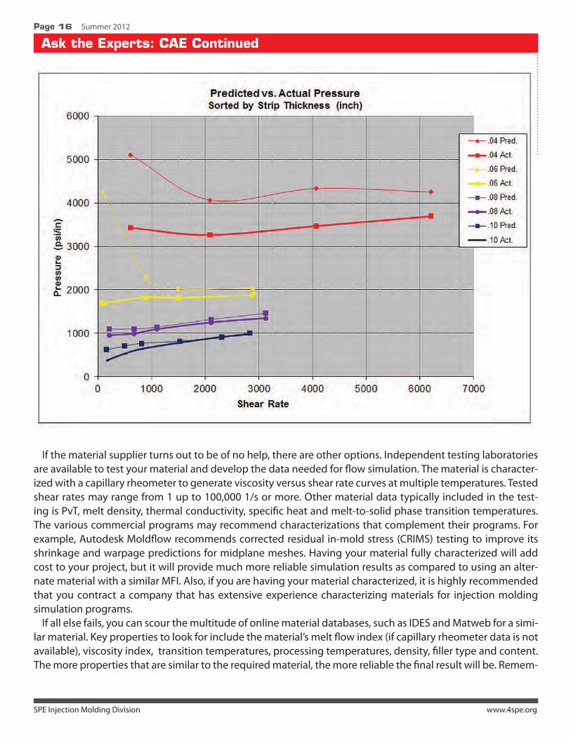
In recognition of these short comings, Beaumont Technologies, Inc. has developed proprietary test methods and an apparatus that correlates mold filling simulation values to actual molded results. This is accomplished by injection molding a given polymer through a wide variaety of specially designed mold geometries at up to 10 different injection rates for each. We collect the in-mold data and correlate the results with the pre-dicted analysis results. Figure 2 is a graphical representation of Veri-flo™ results that contrasts actual molding behavior with mold filling simulation. There are limitations to the data we can collect, but these methods are especially proficient at developing pressure correlations between predicted pressures versus actual in-mold pressure values. More reliable pressure predictions are at the heart of all injection molding simulation pro-grams and improve the ability of the analyst to optimize the application and the resultant designs. Beaumont continues to study and advance the in-mold characterization technology with the goal of providing a better material characterization method for processors, designers and analysts alike.
Design of Experiments for Optimizing Injection Molding
Page 18 Summer 2012
Part 1It is well known amongst injection molders, that stability is the alpha and omega for the process. There are
several approaches to ensure this, but they build on common principles whether you call it systematic set-up, scientific molding or G & A Process Optimization.
It is all based on a good understanding of the process, whereby optimizing the parameters sequentially ensures that each part of the set-up is founded on a correct setting from the previous step.
That has over the years been a well documented way to effectively ensure a good process set-up. But more optimization is possible. First of all, you can ask yourself if optimizing the last parameters does not affect the optimum setting of the first parameters? If so, the set-up has to be an iteration where you return an re-optimize some parameters. The other interesting question you could ask is, if it is possible to determine some “universal solutions” making future set-up or optimizing possible in fewer steps. It could turn out that POM is running at its optimum at the same back pressure in all 30 mm screws in your machines or that a certain product range in general should be produced at the same temperature profile.
Part 2A powerful tool for answering these questions is Design of Experiments (DoE). It is a method for plan-
ning and analyzing experiments. Or rather it is several methods as several people have developed different approaches: Taguchi, Yates and many more, but as the user of DoE this is of less importance.
The purposes for using DoE are:• Pointing out the parameters of importance to the process and the parameters which can rightfully
be ignored.• To determine how much a change of setting will affect product features like dimensions.• To uncover what happens when parameters interact. That meaning something unexpected or
unpredictable happens when changing two or more parameters at the same time.• To gain as much knowledge about the process as possible running as few tests as possible. That way the
Using Design of Experiments for Optimizing Injection Molding
SPE Injection Molding Division www.4spe.org
Design of Experiments for Optimizing Injection Molding Continued
Page 19 Summer 2012
interruption of the production is the least possible and using the fewest possible number of parts for test-ing and measuring afterwards.
Especially the last issue is important if the test must be used for troubleshooting when you really want to reach a conclusion fast.
The idea behind DoE is that before you even start the experiment it is possible to determine how much detail you will go into, how many samples and how to cover several parameters at the same time and how much time must be invested to gain the conclusion. In most situations it is possible to significantly reduce the number of test runs because it might be well known that parameters affect each other, but the main effect is usually from individual parameters or perhaps two interacting parameters. For more information about the background and the math behind DoE a book like Del Vecchios “Understanding Design of Experiments” is a good starting point.
Several tools (software like Minitab®) for setting up and analyzing DoE are available. These tools are used to do the necessary calculations, but the most important factor is the tech-nical know-how and expertise to set-up the criteria for the experiment. What parameters should be investi-gated, how large intervals must be tested and how should the parts be measured or tested? It is obvi-ous to most that not all param-eters have a significant effect on the final part and it is just as evident that there are physi-cal limitations to the pos-sible process adjustments. For these reasons it is very important to involve the persons with technical skills and deep process knowledge when starting to set up a DoE.
Part 3To illustrate the effect of DoE for
injection molding an example could be investigating and optimizing the pro-cess for stability. The goal is to make sure all parameters for plasticizing must be investigated to determine the process-ing window leading to the least pos-sible variation in shot weight. That is the plasticizing settings with the best repeatability and thus least sensitive to effects like raw material variations.
DF Gold Systems offer proven performance advantages, reliability, and cost
effectiveness in the most demanding applications. With more than 50 years
of in-fi eld experience, our technology is supported globally with responsive
technical expertise. That’s INCOE® Hot Runner Performance.
I Proven Performance
I SoftGate® Valve Pin Velocity Control
I Multi Zone Dual Heater Performance
I Unitized, Leak-Proof Reliability
Over 25 Gating Options
I Exclusive Opti-Flo®
Manifold Technology
Technology
with
SPE Injection Molding Division www.4spe.org
Design of Experiments for Optimizing Injection Molding Continued
Page 20 Summer 2012
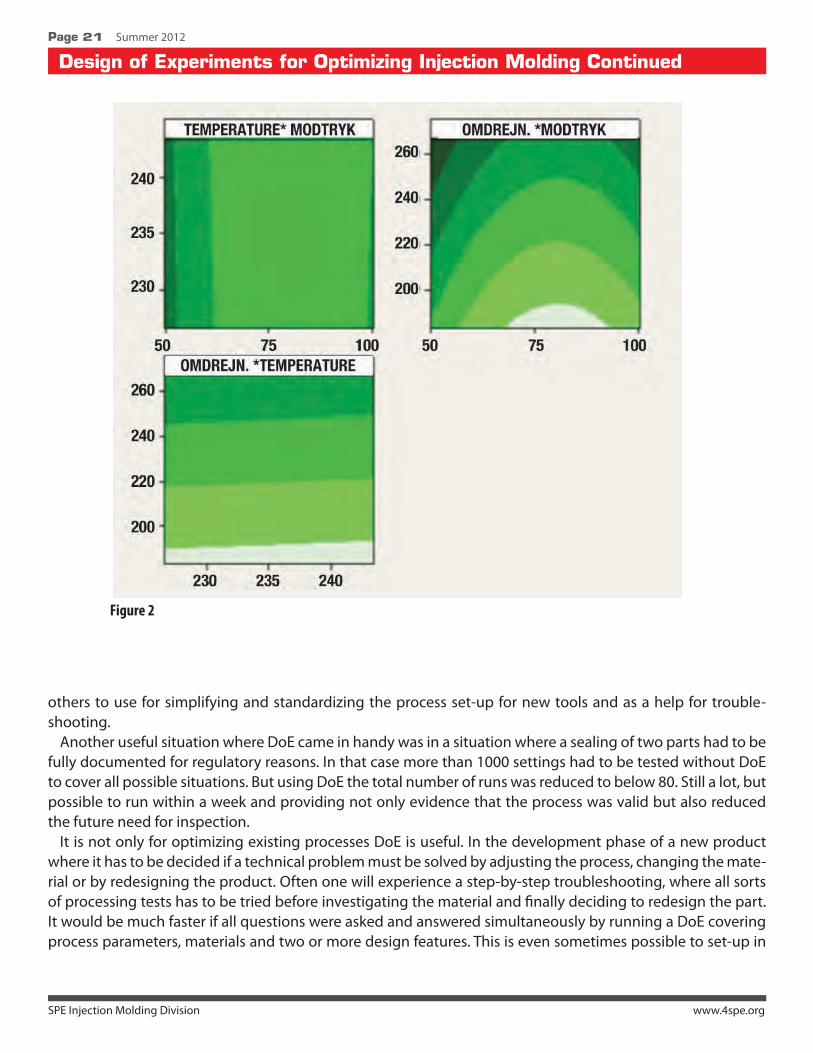
The results from an analysis like that could turn out that screw speed, cylinder temperature and back pres-sure were the significant parameters. By looking at the effect graphically it is quite simple to point out the ideal processing window, but DoE also includes tools for modeling effects to calculate the optimum setting.
As it can be seen in Figure 1 the variation is at its lowest at a back pressure of approximately 75 bar and the temperature can be chosen at any value. But what happens when the third parameter enters the picture?
The upper left graph in Figure 2 shows how Figure1 looks “from above”. The bright areas show where the shot weight variation is low and the dark areas indicates lack of stability in the plasticizing.
As shown, the optimal areas can be placed not only to determine specific values, but intervals. It is thus possible to determine the processing window. In this case a back pressure of 75-90 bar has been chosen from the upper left graph (indicated by the red frame). This interval has then been used in the upper right graph to determine that a low screw speed (180-190 RPM) is recommendable.
The temperature can per se be chosen throughout the tested interval, but in the graph at the bottom where temperature and RPM are combined a small interaction is indicated, showing that the best interval (no dark areas) would be 235-245°.
The conclusion is that it is possible to determine a processing window where it is certain that the stability is acceptable even if the parameters are changed.
Not only processing parameters can be part of a DoE. Using another machine, type of screw or type of ma-terial can be used as a variable in the experiment. That way it can be determined if the selection of machine is critical to part quality or not. At the same time one will obtain data describing what process setting might need to be changed and how they should be adjusted if the machine has a significant effect on the product .
By mapping your processes, machines etc., it is possible to build a library of know-how for tool setters and
Figure 1
SPE Injection Molding Division www.4spe.org
Design of Experiments for Optimizing Injection Molding Continued
Page 21 Summer 2012
others to use for simplifying and standardizing the process set-up for new tools and as a help for trouble-shooting.
Another useful situation where DoE came in handy was in a situation where a sealing of two parts had to be fully documented for regulatory reasons. In that case more than 1000 settings had to be tested without DoE to cover all possible situations. But using DoE the total number of runs was reduced to below 80. Still a lot, but possible to run within a week and providing not only evidence that the process was valid but also reduced the future need for inspection.
It is not only for optimizing existing processes DoE is useful. In the development phase of a new product where it has to be decided if a technical problem must be solved by adjusting the process, changing the mate-rial or by redesigning the product. Often one will experience a step-by-step troubleshooting, where all sorts of processing tests has to be tried before investigating the material and finally deciding to redesign the part. It would be much faster if all questions were asked and answered simultaneously by running a DoE covering process parameters, materials and two or more design features. This is even sometimes possible to set-up in
Figure 2
SPE Injection Molding Division www.4spe.org
Design of Experiments for Optimizing Injection Molding Continued
Page 22 Summer 2012
the Mold Flow analysis even before building the tool — and in simulations the DoE is just as useful since simu-lations, interpretations and reporting takes time and costs money.
Part 4DoE is an efficient way to control your tests and make well-informed conclusions even if one experiment
ends in a need for more testing as part of the analysis is finding the right course for further improvements. It can be used for very detailed analysis but is just as useful if you only need a general course of direction for further investigations.
The statistics behind DoE can seem intimidating, but if you are familiar with basic statistics it is not an insur-mountable task and by using dedicated software for the calculations you will through it fast and easy. As the analysis of the results is based on well known statistical methods, the DoE also gives you a strong documen-tation for the process and the product which is highly useful whether it is for validation purposes or simply because you see the value in a well documented process that would ease future troubleshooting.
About the AuthorM.Sc. Carsten Lund established Epsilon in September 2009. He has Master degree at Polytehcnical University of
Denmark at the department of plastic technology in the institute of process technology. He has a black belt Lean/Six Sigma training at SBTI and has been working with injection molding and process optimizations for more than a decade. Epsilon rests on three pillars: Process analysis (primarily Injection Molding), GMP and Six Sigma. These three concepts supports each other well as validation must be founded on statistical evidence and because the op-timization of many processes can be rather complex Six Sigma is very advantageous. Epsilon addresses companies who need help for optimizations, validation, quality management, process mapping, data analysis and measure-ment system analysis. More information can be found at www.epsilonplus.dk/eng
Mark A. Spalding, The Dow Chemical Company
Midland, MI
Gregory A. Campbell, Castle Research Associates
Jonesport, ME
IMD Best Paper
SPE Injection Molding Division www.4spe.org
Page 24 Summer 2012
Black specks and color streaks in injection molded parts can reduce the yield and profitability of an injection molding process. This paper presents some of the common root causes for black specks and color streaks, and the technical solutions to remove them. Three case studies are presented.
IntroductionInjection molding processes must be able to operate at low cycle times and high yields to remain competi-
tive in the market place. Once a process is optimized for rate and thus minimum cycle times, loss of yield can reduce the profitability of a plant. Yield can be reduced by off dimension parts due to improper shrinkage, short shots, surface defects known as splay, black specks, and color streaks. Black specks and color streaks can originate from the feedstock resin, the plasticator, non-return valve, and the runner system. The focus of this paper is the troubleshooting of black specks and color streaks that originate from the plasticator.
The goal of this paper is to provide common troubleshooting techniques to determine root causes for black specks and color streak contamination in injection molded parts. Three case studies are presented that show these problems. Although black specks can originate from any flow section of the process, the plasticator is the focus of this paper.
BackgroundThe diagnosis of the root cause
and the technical solution to elimi-nate a defect can be difficult, time consuming, and costly to identify. The time required troubleshooting a process and thus the cost can be decreased if a systematic approach is used. This approach starts by verifying operational data, per-forming simple calculations, and developing strong hypotheses1-5. Next, the troubleshooter must develop experiments that either
Troubleshooting Black Specks and Color Streaks in Injection Molded Parts
�� ��������
�� �����
�� ������
�� �����
�
������������������ ������������������
������������������������ !�����������
SPE Injection Molding Division www.4spe.org
IMD Best Paper Continued
Page 25 Summer 2012
validate or invalidate the hypotheses. Once the root cause is determined, the best technical solution will de-pend on many factors including the cost of lost production, the time and cost to implement, machine owner acceptance, and the risk associated with the modified process.
Several root causes exist for black specks and color streak contamination in molded parts. These root causes include degradation of the resin in the screw channels, non-return valve, and runner system 6-9, degraded material or contamination entering with the resin feedstock, and poorly dispersed pigments in the color masterbatch 10. For example, screws that have very small flight radii at the pushing and trailing screw flights can allow resin to have very long residence times here due to Moffat eddies 11. These regions can cause resin to degrade, and the degradation products will eventually contaminate the part with black specks. Mixing sec-tions can often have stagnant regions that lead to resin degradation. For example, the exit and entry regions of a spiral dam can cause resin degradation if they are not designed properly 9.
The metering section of the screw must be the rate controlling step for plastication. If the metering section is not rate controlling, then the metering section will operate partially filled with resin. Partially filled channels will have a portion of the channel that is stagnant, allowing resin to degrade 6,8. The troubleshooter should always verify that the metering section is operating as the rate controlling step. The rate calculation for the metering section can be found elsewhere 12,13.
Black Specks in a Beige PartA small interior automotive part was injection molded using a 700 ton press equipped with a 105 mm
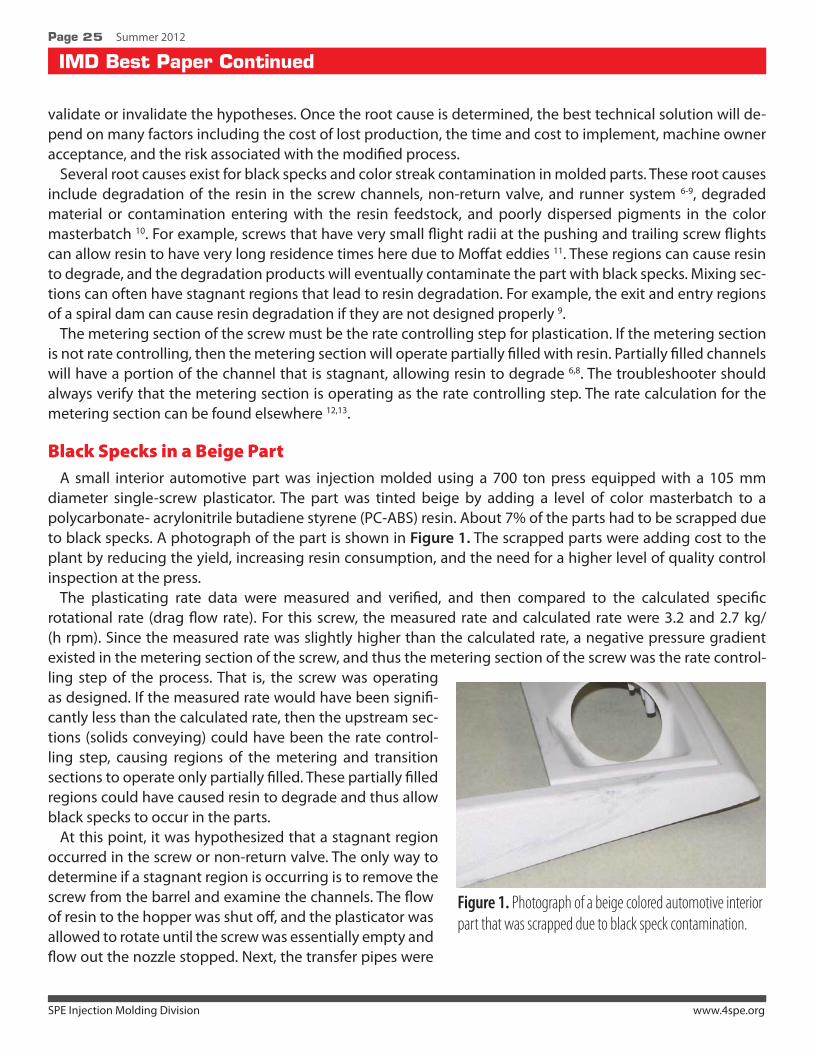
diameter single-screw plasticator. The part was tinted beige by adding a level of color masterbatch to a polycarbonate- acrylonitrile butadiene styrene (PC-ABS) resin. About 7% of the parts had to be scrapped due to black specks. A photograph of the part is shown in Figure 1. The scrapped parts were adding cost to the plant by reducing the yield, increasing resin consumption, and the need for a higher level of quality control inspection at the press.
The plasticating rate data were measured and verified, and then compared to the calculated specific rotational rate (drag flow rate). For this screw, the measured rate and calculated rate were 3.2 and 2.7 kg/(h rpm). Since the measured rate was slightly higher than the calculated rate, a negative pressure gradient existed in the metering section of the screw, and thus the metering section of the screw was the rate control-ling step of the process. That is, the screw was operating as designed. If the measured rate would have been signifi-cantly less than the calculated rate, then the upstream sec-tions (solids conveying) could have been the rate control-ling step, causing regions of the metering and transition sections to operate only partially filled. These partially filled regions could have caused resin to degrade and thus allow black specks to occur in the parts.
At this point, it was hypothesized that a stagnant region occurred in the screw or non-return valve. The only way to determine if a stagnant region is occurring is to remove the screw from the barrel and examine the channels. The flow of resin to the hopper was shut off, and the plasticator was allowed to rotate until the screw was essentially empty and flow out the nozzle stopped. Next, the transfer pipes were
�
Figure 1. Photograph of a beige colored automotive interior part that was scrapped due to black speck contamination.
SPE Injection Molding Division www.4spe.org
IMD Best Paper Continued
Page 26 Summer 2012
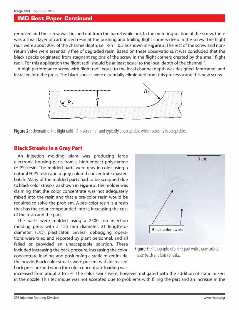
removed and the screw was pushed out from the barrel while hot. In the metering section of the screw, there was a small layer of carbonized resin at the pushing and trailing flight corners deep in the screw. The flight radii were about 20% of the channel depth; i.e., R/h = 0.2 as shown in Figure 2. The rest of the screw and non-return valve were essentially free of degraded resin. Based on these observations, it was concluded that the black specks originated from stagnant regions of the screw in the flight corners created by the small flight radii. For this application the flight radii should be at least equal to the local depth of the channel 7.
A high performance screw with flight radii equal to the local channel depth was designed, fabricated, and installed into the press. The black specks were essentially eliminated from this process using this new screw.
Figure 2: Schematic of the flight radii. R1 is very small and typically unacceptable while radius R2 is acceptable.
Black Streaks in a Gray PartAn injection molding plant was producing large
electronic housing parts from a high-impact polystyrene (HIPS) resin. The molded parts were gray in color using a natural HIPS resin and a gray colored concentrate master-batch. Many of the molded parts had to be scrapped due to black color streaks, as shown in Figure 3. The molder was claiming that the color concentrate was not adequately mixed into the resin and that a pre-color resin would be required to solve the problem. A pre-color resin is a resin that has the color compounded into it, increasing the cost of the resin and the part.
The parts were molded using a 2500 ton injection molding press with a 125 mm diameter, 21 length-to- diameter (L/D) plasticator. Several debugging opera-tions were tried and reported by plant personnel, and all failed or provided an unacceptable solution. These included increasing the back pressure, increasing the color concentrate loading, and positioning a static mixer inside the nozzle. Black color streaks were present with increased back pressure and when the color concentrate loading was increased from about 2 to 5%. The color swirls were, however, mitigated with the addition of static mixers in the nozzle. This technique was not accepted due to problems with filling the part and an increase in the
�Figure 3: Photographs of a HIPS part with a gray colored masterbatch and black streaks.
IMD Best Paper Continued
Page 27 Summer 2012
cycle time. The static mixers required that the injection pressure be increased to un-acceptable levels to maintain cycle time.
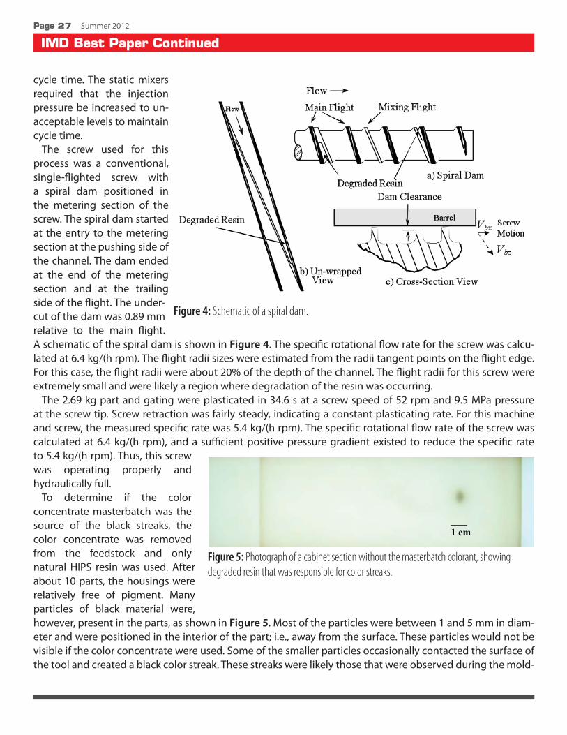
The screw used for this process was a conventional, single-flighted screw with a spiral dam positioned in the metering section of the screw. The spiral dam started at the entry to the metering section at the pushing side of the channel. The dam ended at the end of the metering section and at the trailing side of the flight. The under-cut of the dam was 0.89 mm relative to the main flight. A schematic of the spiral dam is shown in Figure 4. The specific rotational flow rate for the screw was calcu-lated at 6.4 kg/(h rpm). The flight radii sizes were estimated from the radii tangent points on the flight edge. For this case, the flight radii were about 20% of the depth of the channel. The flight radii for this screw were extremely small and were likely a region where degradation of the resin was occurring.
The 2.69 kg part and gating were plasticated in 34.6 s at a screw speed of 52 rpm and 9.5 MPa pressure at the screw tip. Screw retraction was fairly steady, indicating a constant plasticating rate. For this machine and screw, the measured specific rate was 5.4 kg/(h rpm). The specific rotational flow rate of the screw was calculated at 6.4 kg/(h rpm), and a sufficient positive pressure gradient existed to reduce the specific rate to 5.4 kg/(h rpm). Thus, this screw was operating properly and hydraulically full.
To determine if the color concentrate masterbatch was the source of the black streaks, the color concentrate was removed from the feedstock and only natural HIPS resin was used. After about 10 parts, the housings were relatively free of pigment. Many particles of black material were, however, present in the parts, as shown in Figure 5. Most of the particles were between 1 and 5 mm in diam-eter and were positioned in the interior of the part; i.e., away from the surface. These particles would not be visible if the color concentrate were used. Some of the smaller particles occasionally contacted the surface of the tool and created a black color streak. These streaks were likely those that were observed during the mold-
Figure 4: Schematic of a spiral dam.
�Figure 5: Photograph of a cabinet section without the masterbatch colorant, showing degraded resin that was responsible for color streaks.
SPE Injection Molding Division www.4spe.org
IMD Best Paper Continued
Page Summer 2012
ing of the cabinets with the color concentrate. It was hypothesized that the black particles were degraded resin that was coming from the stagnant regions of the screw and non-return valve. The next step was to remove the screw and look for stagnant regions.
To locate the regions where the material was degrading in the screw, pellet flow to the screw was stopped and rotation of the screw was continued until all natural HIPS resin emptied from the plasticator. Next, the screw was removed from the barrel and examined for black and degraded resin. There was a relatively large amount of severely degraded resin at the entry to the spiral dam on the collection side of the channel, as shown in Figures 4 and 6. This region is known to be a place for long residence times; i.e., a location for resin degradation. The degraded resin was soft, leathery, and black in color. There was also a considerable amount of this degraded material at both the pushing and trailing flight radii, starting in the middle of the transition section and extending the rest of the length of the screw. The non-return valve also had considerable levels of black degraded resin adhering to its surface. These leathery, black flecks were the root cause of the black colored swirls in the parts. It is not known whether the screw or the non-return valve was the major contribu-tor of the black specks. These procedures convinced the plant personnel that it was their process equipment that was creating the black color streaks and not the resin or the color concentrate masterbatch. The only permanent solution to this problem was to eliminate the regions where the polymer was degrading. That is, the existing screw and non-return valve needed to be replaced with streamlined equipment; i.e., a screw and non-return nozzle that does not have regions with long residence times for the resin.
A high-performance screw was designed for the injection molding press. This screw was designed with a much higher compression ratio and with large flight radii in all sections of the screw. The press was started
back up using the high-performance screw and natural HIPS resin with 2% of a light gray color concentrate master-batch. For this startup the same 2.69 kg part was produced and the barrel set point temperatures were the same as before. After steady operation was obtained (about 10 parts), the 2.69 kg part and gating were plasticated in 33.5 s at a screw speed of 52 rpm and 9.5 MPa pressure at the screw tip. The screw retraction rate was steady, indicating a constant plasticating rate. The measured specific rate was 5.6 kg/(h rpm), a specific rate that was about 3% higher than that for the original screw. The specific rotational flow rate of the screw was calculated at 7.1 kg/(h rpm), and a sufficient positive pressure gradient existed to reduce the specific rate to 5.6 kg/(h rpm). Thus, this screw was operating properly and hydraulically full. During the remainder of the trial, black color streaks were never observed.
The high-performance screw was monitored closely for about one month after its installation. During this period, black color streaks were never observed, and plant personnel have indicated that the problem was solved.
�
Figure 6: Photograph of the entry to the spiral dam of the screw, showing dark degraded resin due to long residence times.
SPE Injection Molding Division www.4spe.org
IMD Best Paper Continued
Page 29 Summer 2012
Pigment Steaks in a Gray PartAn injection molding plant was producing large
parts from a natural polypropylene (PP) resin. The natural resin was blended with a 35 to 1 letdown ratio of a light gray color concentrate. The molder was ex-periencing problems with black streaks on the surface of the parts, causing a high scrap rate. A photograph of the black streaks is shown in Figure 7. When the back pressure on the screw was increased from 0.7 MPa to 2.5 MPa, the fraction of parts with black streaks decreased from 50% down to less than 10%.
The injection molding press was equipped with a 140 mm diameter, 20 L/D plasticator. The press was designed with a pressure intensification factor of 10. That is, for a back pressure setting of 2.5 MPa the pressure at the discharge of the screw during rota-tion was 25 MPa. The specific rotational flow rate for the metering section of the screw was calculated at 9.5 kg/(h rpm). Due to the very short metering section length (2 diameters), the specific rate that the screw will operate at will be highly dependent on the discharge pressure during operation; i.e., the back pressure setting. The screw was capable of operating at a maximum speed of 99 rpm.
This press had a new barrel, barrier screw, and non-return valve, and the press had been thoroughly inspected for operation. The molder had spent considerable time working with the current process to achieve the best results. They concluded that high temperatures helped with the recovery time and minimized the level of defects. The main concern was that the defects were coming from the degradation of the PP resin or were related to the masterbatch colorant. Some adjustments were made to increase the back pressure and decrease the barrel temperatures, resulting in a constant barrel or “flat” temperature profile. The molder determined that a constant barrel temperature profile at 235°C, coupled with 2.5 MPa back pressure allowed a more consistent operation of the barrel heating zones and more consistent recovery time while minimiz-ing the level of color streaks. The cycle time, however, increased to an unacceptable level of 85 s with the plasticating process limiting the rate.
At the start of the trial, the target for the plant was to run a 65 s cycle time with a 1% scrap rate or less due to all defects. The plasticator was running at 235°C for all four barrel zones, a screw speed of 99 rpm, and with a back pressure of 2.5 MPa. The barrel zone located over the metering section of the screw was measured at 262oC, a temperature that was more than 25oC over the set point temperature. For this case, the cooling capability of the zone was unable to remove the dissipated energy fast enough. This process gave a cycle time of 82 s, but kept the scrap rate at the lowest and about 10%. The plasticating time was 36 s, and the instantaneous specific rate for this process was measured at 3.45 kg/(h rpm). This plasticating rate was consid-erably less than the calculated rotational flow rate for the screw; i.e., the rotational flow rate for the screw was calculated at 9.5 kg/(h rpm). This press was rate limited by the current 36 s plasticating time. Observations showed slight inconsistencies for the screw plasticating times. Although these inconsistencies were minor, they were a concern that the screw and plasticator were not functioning properly. The injectate temperature was
�Figure 7: Photograph of the black colored streaks in a PP molded part.
SPE Injection Molding Division www.4spe.org
IMD Best Paper Continued
Page 30 Summer 2012
measured by producing an “air shot” and then measuring the temperature using a hand-held temperature sensor. An air shot is when the nozzle of the plasticator is pulled away from the mold, and then the material is discharged onto a piece of cardboard, creating a molten mass of material that can be viewed. The injectate temperature was measured at 259°C, a temperature that is considered relatively high for this type of process.
In order to understand why the plasticator operated at a low specific rate, several changes were made to the process. First the back pressure was decreased to 1.4 MPa for a discharge pressure of 14 MPa. This allowed the plasticating time to decrease to 21 s and the specific rate to increase to 5.9 kg/(h rpm). The parts produced at these conditions were 100% scrap due to black streaks. This increase in specific rate and a flow calculation confirmed that the discharge pressure was responsible for the low specific rates.
Next, the color concentrate flow was turned off and allowed to run out. The color was removed from the system to determine whether the color streaks were caused by degraded PP resin or from poorly compound-ed pigments into the color concentrate. If the streaks were caused by degraded resin, the streaks should still be present after the color concentrate is removed. Once the parts were completely natural in color, there were no black streaks present in the parts. The screw speed and back pressure were varied between 50 and 90 rpm and between 0.7 and 2.5 MPa, respectively, in an attempt to disrupt the process. The hypothesis was that if any degraded resin had accumulated on the screw due to a poor screw design, then the variations in screw speed and back pressure would cause the degraded resin to exit with the injectate, creating streaks in the parts. In all cases, the parts did not contain streaks, indicating that the screw was operating properly with the natural PP resin. The process data indicated that molder could operate the screw at 99 rpm and a back pressure of 0.7 MPa to produce high-quality parts with a cycle time of 65 s or less.
The molding conditions were returned to the original settings of a screw speed of 99 rpm and a back pressure of 2.5 MPa and then the masterbatch colorant was added back into the process at a letdown ratio of 35 to 1. As soon as the colorant was observed in the parts, the black streaks re-appeared. Based on the data here the root cause for the black streaks was the color concentrate. Although not completely evaluated, it is likely that pigment agglomerates in the masterbatch were created during the compounding operation. These agglomerates cannot be effectively dispersed using this barrier screw. When the back pressure was increased to 2.5 MPa, the mixing abilities of the screw increased slightly and the level of streaks in the parts decreased. The obvious goal was to obtain a color concentrate free of agglomerated pigment particles, allowing the press to operate using a back pressure of 0.7 MPa and a minimum cycle time.
The melt flow rate (MFR) for the PP resin and the masterbatch colorant were measured to see if the master-batch material meets the criteria defined by Benkreira and Britton [10]. Benkreira and Britton’s mixing experi-ments indicated that the viscosity ratio at the processing conditions of the natural resin to that of the master-batch resin should be as high as possible. Masterbatches with very low viscosities, however, can be difficult to produce since the stresses during the compounding operation may not be high enough to disperse the pig-ments. In general and as a compromise, the viscosity of the masterbatch at processing conditions should be about one half that of the natural resin. The MFRs were 20 and 116 dg/min (230°C, 2.16 kg) for the natural PP resin and the masterbatch colorant, respectively. Obviously, the color concentrate masterbatch was not well matched for the natural PP resin according to the guidelines developed by Benkreira and Britton. That is, the carrier resin used to make the masterbatch was too low in viscosity to allow the breakup of pigment agglom-erates during the twin-screw compounding process. If the pigment, however, could have been dispersed in this carrier resin, the masterbatch would have been acceptable. Comparing the shear viscosity of the natural resin and the masterbatch is preferred over comparing the MFRs. For these materials, the shear viscosity of the natural PP resin and the color masterbatch were 160 and 40 Pa.s, respectively, at processing conditions.
SPE Injection Molding Division www.4spe.org
IMD Best Paper Continued
Page 31 Summer 2012
As expected the ratio of the shear viscosity for the natural resin to that of the concentrate was about 4, a value larger than the guideline value of 2. A better masterbatch could be made with a more viscous carrier PP resin such that additional stress can be applied during the compounding step to aid in the dispersion of the pigment agglomerates.
Due to preset specifications, changing the color concentrate masterbatch was an unacceptable technical solution for the plant. Instead, the pigment agglomerates in the masterbatch would need to be dispersed in the plasticator of the injection molding machine. That is, a new screw would need to be designed and fabricated that is capable of dispersing the agglomerates while meeting the cycle time of 65 s. A high-perfor-mance screw with a spiral mixer was chosen for the application. This screw was designed with multiple dis-persing dams in the high-performance section, providing a gap between the peak of the dam and the barrel wall of 1.1 mm. The clearance between the mixing flights of the spiral mixer and the barrel wall were 0.89 mm. The dispersing ability of this screw was considerably higher than the original screw. The original screw had a barrier flight undercut gap of about 1.5 mm and a spiral mixer undercut of 4.8 mm.
The high-performance screw was installed and trialed. The screw immediately produced high-quality parts without black streaks and with a cycle time of 65 s. The plasticating time was 15 s at a screw speed of 99 rpm for a specific rate of 8.3 kg/(h rpm). This specific rate is just slightly less than the calculated specific rotational rate of 8.9 kg/(h rpm). The back pressure used for this plastication was 0.7 MPa. These results indicate that the dispersion gaps on the high-performance screw were small enough to provide a high enough stress level to disperse the pigment agglomerates that were in the color concentrate masterbatch.
DiscussionFor many resins, long residence times in the flow path will cause the resin to degrade into dark colored
material. If the degraded resin comes off of the metal surface where they formed, they will flow downstream and result in black specks or color streaks. These black specks and color streaks are easy to observe and diagnose in parts that are not black or gray colored. In almost all cases, the screw must be removed from the barrel to determine the source. Common sources include regions where the flow is stagnant such as partially filled metering channels, small flight radii, and mixers that are not streamlined.
For gray colored parts, black specks may originate from the screw design problems discussed above or they could be poorly dispersed pigment in the masterbatch. Removing the masterbatch from the feedstock is the best method to determine if the black specks are from the screw or from the pigment.
Conclusions
Troubleshooting and elimination of black specks and color streaks from injection molding parts is present-ed. Three cases studies are presented that show root causes and the technical solutions to eliminate the prob-lems. The work focuses on the plasticator, although downstream sections of the process can cause resin to degrade and form black specks.
References1. J.R. Platt, Science, 146, 347 (1964).2. M.A. Spalding and G.A. Campbell, G.A., SPE-ANTEC Tech. Papers, 57, 1392 (2011).3. R.J. Gould, “Introduction – Basics of Extrusion Troubleshooting,” in “The SPE Guide on Extrusion Tech-
nology and Troubleshooting” Chapter I, Edited by J. Vlachopoulos and J.R. Wagner, SPE, 2001.
SPE Injection Molding Division www.4spe.org
IMD Best Paper Continued
Page 32 Summer 2012
4. R.F. Mager, “Troubleshooting the Troubleshooting Course or Debug D’Bugs,” Center for Effective Per-formance, Atlanta, Georgia, 1983.
5. H.S. Fogler and S.E. LeBlanc, “Strategies for Creative Problem Solving,” Prentice Hall PTR, Upper Saddle River, New Jersey, 1995.
6. K.S. Hyun, M.A. Spalding, and J. Powers, SPE-ANTEC Tech. Papers, 41, 293 (1995).7. M.A. Spalding, J. Dooley, J., and K.S. Hyun, SPE-ANTEC Tech. Papers, 45, 190 (1999).8. M.A. Spalding, SPE-ANTEC Tech. Papers, 50, 329 (2004).9. M.A. Spalding and J. Powers, SPE-ANTEC Tech. Papers, 55, 2463 (2009).10. H. Benkreira and R.N. Brittin, R.N., Int. Polym. Process., 9, 205 (1994).11. H.K. Moffat, J. Fluid Mech. 18, 1 (1964).12. Z. Tadmor and I. Klein, “Engineering Principles of Plasticating Extrusion,” Van Nostrand Reinhold Com-
pany, New York, 1970.13. M.A. Spalding and K.S. Hyun, “The Plasticating System for Injection Molding Machines,” Chapter 3 in
“Injection Molding, Fundamentals and Applications” ed. Kamal, M.R., Isayev, A.I., and Liu, S-J., Hanser, Munich, 2009.
Coming This Summer:• The Engineer as a Business Person—Things You Need to Know
• Accelerated Weathering of Plastics
• Impact of Plastics Materials
• Part Design for Extrusion
• Plastic Materials Selection
• Metal Replacement
Increase your knowledge of the plastics industry and improve your job performance, all from the convenience of your home or office. Internet access/phone line required.
For more information on these webinars or for more listings of webinar events visit www.4spe.org
SPE Injection Molding Division www.4spe.org
Feature
Page 33 Summer 2012
IMD Board of Directors Meeting
SPE Injection Molding Division www.4spe.org
Page 34 Summer 2012
Welcome Chair Susan Montgomery called the meeting to order at 9:00 am ET, and welcomed all attendees. Susan
asked Tom Turng to introduce his guest Dr. Sreekanth Pilla from Wisconsin Institute of Discovery. Later in the meeting, Mal Murthy introduced his guest, Rick Puglielli, President of Promold Plastics. The Board welcomed Sreekanth, Rick and SPE staff Tricia Mcknight, Barbara Spain and Margie Weiner.
Susan led the Board in a moment of silence in remembrance of Emeritus Director Don Allen and Mrs. Frances Grelle, Peter’s mother, both of whom had recently passed away.
Roll CallPresent in person were:Susan Montgomery (Chair), Jim Wenskus; Peter Grelle; Hoa Pham; Pat Gorton; Erik Foltz, Adam
Kramschuster; Jack Dispenza, Nick Fountas; Larry Schmidt; Lee Filbert; Tom Turng; Michael Uhrain; Jeremy Dworshak, David Kusuma; David Okonski, Mal Murthy (Emeritus),
Guests were: Srikanth Pilla, Rick Puglielli, Tricia McKnight, Barbara Spain, and Margie Weiner
Absent were: Brad Johnson (at Council meetings), Kishor Mehta, Raymond McKee
This constituted quorum.
Approval of February 3, 2012 Meeting MinutesThe meeting minutes of February 3, 2012 were presented.
Motion: Peter Grelle moved that the February 3, 2012 meeting minutes be approved, as written and distrib-uted. Jim Wenskus seconded and the motion carried.
Pinnacle Award – Susan MontgomerySusan announced that the Division received the Pinnacle Award, Gold level. She would receive the award on
behalf of the Division at the Award Luncheon.
Nomination Committee – Hoa Pham, ChairHoa presented the results of the Board elections. Pat Gorton, Raymond McKee, Adam Kramschuster, Jeremy
Dworshak and Lee Filbert were elected to the Board for a three-year term, ending at ANTEC 2015.
Officers for the 2012 – 2013 Board are: Susan Montgomery (Chair), Erik Foltz (Chair-Elect), Jim Wenskus (Trea-surer), Peter Grelle (Technical Director), Brad Johnson (Councilor) and Hoa Pham (Secretary). The TPC for Antec 2013 is Pat Gorton.
April 1, 2012 –Orlando, FLSubmitted by Hoa Pham, Secretary
IMD Board of Directors Meeting Continued
SPE Injection Molding Division www.4spe.org
Page 35 Summer 2012
Financial Report – Jim Wenskus, TreasurerFinancial figures from July 1, 2011 through February 29, 2012 were reviewed. SPE Rebate was on target.
Discussions ensued on collecting sponsorship payments. Jim mentioned that he had finalized the PayPal process. Sponsors now can pay either through PayPal or the SPE office. The IMD pays a small fee for this service.
Expenses were reviewed. Jim noted that the report did not include recent payments for ANTEC activities, such as Gold level support for student activities, cost of award plaques, cost of the IMD reception, and other expenses. Updates would be provided at the next meeting.
The proposal for 2012 – 2013 budget was reviewed. The budget for SPE rebate was updated to reflect the new program.
SPE Update – Barbara Spain Barbara Spain reported that the ANTEC 2012 proceeding was e-mailed to ANTEC registrants. The e-mail
included a link to access or download the proceeding. Barbara also gave updates on activities to revamp the webinar program to increase attendance. Work has been in progress on the extrusion series. Susan proposed that the IMD Board consider the feasibility of organizing a molding series. The primary contact for the Board is Peter Grelle.
Action Item: Pete Grelle to initiate the discussions to consider an injection molding series.
ANTEC 2012 Report – Erik Foltz, TPCErik gave an update on the IMD technical program for ANTEC 2012. Slides for in-between presentations
would be e-mailed to all moderators. ANTEC meeting rooms would be in the Convention Center South Building. Erik asked the moderators to do a headcount, complete the moderator sheets and give them to the door monitors.
Discussions on future ANTEC conferences were conducted. ANTEC 2013 would be April 22 – April 24 in Cin-cinnati. The dealine for papers would be in October 2012. ANTEC 2014 would be April 27 – May 1 in Las Vegas. David Okonski expressed concern that some attendees would face difficulty in getting their organization’s approval to travel to Las Vegas for the conference.
Barbara Spain noted that the SPE direction was to build on the ‘ANTEC’ brand name. So, there would be ‘regional’ ANTEC conferences world wide, such as ANTEC-Mumbai which would send out call for papers at the end of April 2012.
The discussions culminated in the Board joining Susan in thanking Erik for his efforts in organizing a great ANTEC program for the IMD.
Technical Director Report – Peter GrellePeter thanked the Board for the flowers and condolences for his mother’s funeral. Peter reported that he has been involved with the Detroit section, and proposed that the IMD co-sponsor
local plant visits.
IMD Board of Directors Meeting Continued
SPE Injection Molding Division www.4spe.org
Page 36 Summer 2012
Discussions about having a TOPCON in India and China have started between Brad Johnson and John Ratzlaff. Additional discussions would be necessary to formulate how the IMD could participate in these conferences.
Peter was still not able to connect with the Upper Midwest section for the medical conference. He also tried several times to connect with the Philadelphia Section but no progress after the initial contact. Tricia said she could help with the contact.
Action Item: Pete to follow-up with SPE for a contact at the Philadelphia section, and to revive discussions with this section for a possible joint TOPCON.
Education Committee – Pat Gorton, Chair Pat reported that he invited MAPP to speak to the Board. However due to schedule conflict, the MAPP
representative could not attend. Susan also contacted Bill Tobin to speak to the Board because Bill has been training for many years and could provide some insights into industry needs for training.
Bill gave his presentation after Adam’s report.
Communications Committee Report – Adam Kramschuster Adam gave an update on the newsletter. The Spring edition had been distributed. Content for the Summer
edition is due on June 10, 2012. Adam reviewed the sponsorship list. Currently the newsletter is self-funding.The administrators of the Facebook page are Adam and Raymond McKee. Adam asked Board members with
Facebook accounts to ‘like’ the IMD page.Adam was finalizing the renewal contract with Heidi.
Guest Speaker – Bill Tobin, “Effective Technician Training”
Bill presented his perspectives and experience in training the technician. He gave some examples of how training helped molding companies improve their process and profitability.
Councilor Report – Brad Johnson, CouncilorAttending Council meetings.
Membership Committee – Nick Fountas, Chair No report
Fast Track Program, Fellows & HSM Committee – Larry Schmidt, ChairLarry reported that there was no new update on Fellows & HSM. He asked the Board to recommend candi-
dates. The SPE had seminar programs in the past. Three years ago, SPE HQ decided to discontinue the seminars
for cost-savings. Recently, PTI proposed to revive the seminars, with the agreement that PTI would organize and run the program while the SPE provided the brand (SPE logo). In 2011 at ANTEC-Boston, the SPE had 9 seminars, three of which were injection molding. PTI now organized the Fast Track Program, which would of-fer different tracks such as injection molding, extrusion, blow molding, thermoforming and part design. This scheme would allow registrants to attend more than one seminar within the track. PTI suggested that the Di-
IMD Board of Directors Meeting Continued
SPE Injection Molding Division www.4spe.org
Page 37 Summer 2012
vision consider promoting the Fast Track Program in newsletter, website, and perhaps Facebook. The Division could also partner with PTI to organize a seminar program, which would potentially provide some revenue for the Division. David Kusuma noted that OEMs would be more inclined to support their employees to attend seminars about innovation or best practices.
Old BusinessNone discussed.
New BusinessTom Turng mentioned that the University of Wisconsin would hold their Colloquium in Wisconsin after AN-
TEC. Jack informed the Board that he would be the SPE Membership Chair, and gave a brief update.
AdjournmentMotion: Adam Kramschuster made a motion to adjourn the meeting. Tom Turng seconded and the motion
The Stout University Foundation announces that a new endowed scholarship has been established for eligible upper classmen pursuing a Plastics Engineering Degree at the University of Wisconsin-Stout. An alumni group, honoring a 1962 Stout grad killed in action in Vietnam, spearheaded the initiative to establish the memorial and scholarship. The recently inaugurated Plastics Engineering Degree program at Stout will equip graduates with the skills essential to immediately contribute to the growth of the plastics industry.
The John Leon Abrams Memorial Scholarship is named for Lt. Abrams, a Navy helicopter pilot attached to an elite attack group named the Seawolves, who supported SEAL and Special Forces in the Mekong Delta region of Vietnam. The Seawolves experienced greater than a 30% attrition rate due to their dangerous missions, where they inserted, extracted, provided air cover, patrolled and rescued elite US and Allied forces.
The annual scholarship will both honor Lt. Abrams and benefit the next generation of plastics professionals. An endowed fund is established and individual or company tax deductible contributions are encouraged to provide the funding necessary to permanently sustain the scholarship. The administration, collection and distribution of funding are under the auspices of the Stout University Foundation.
Contributions are to be sent to:
The University of Wisconsin – Stout University Foundation
Tetra Pak Packaging Solution ABTexas A&M UniversityThe Lubrizol Corp.Ticona AutomotiveTNT Plastic Molding DivisionTomas Bata U.Toyota Tsusho (Australasia) Pty. Ltd.Tupperware Brands Corp.Turck Inc.Uflex Ltd.United Solar OvonicsU. CincinnatiU. Technology-DresdenU. Wisconsin-MadisonU. Wisconsin-StoutVari-Tek Co.Vision Technical Molding LLCVistakon - Johnson & JohnsonWG Strohwig Tool & DieWacker Chemical Corp.Wagener & Associates Inc.WAL Consulting (HK) Ltd.Washington Penn Plastic Co.WDIWestern Washington U.Westminster Tool IncWestmoreland Plastics Co.Xten IndustriesZeiger IndustriesZirc Co.
Membership Application
SPE Injection Molding Division www.4spe.org
Page 45 Summer 2012
Publisher Note | Sponsors
SPE Injection Molding Division www.4spe.org
Page 46 Summer 2012
The SPE Injection Molding Division has joined the ranks on facebook. There you will find all Molding Views issues, news, events and more! See what’s going on in your IM community by stopping by for a visit at: http://www.facebook.com/SPEInjectionMoldingDivision Have a news item for our facebook community? Send it in to share with your IM Members!
I also want to thank everyone for there support. Keep sending in your articles! It’s a great way to share your know-lege with your peers. Have a great summer and see you in the Fall!
TERRA Community College ......................................... 38www.terra.edu
Support Your Injection Molding DivisionWe are always accepting sponsors and writers for each issue. Your support puts your company in front of over 5000 professionals in the Injection Molding Industry. The Injection Molding Division publication is issued three times a year to current and past members worldwide.
For more information on sponsorships and/or articles please e-mail: [email protected]
A big thank you to the authors and sponsors who supported