20
1 Page 2-18 Installation Manual IP Video Door Station D1812 Series VERSION 1.3, MIN. HW 1.3 D1812

1
Page 2-18Installation Manual IP Video Door Station D1812 Series
VERSION 1.3, MIN. HW 1.3D1812

2
INSTALLATION MANUAL
Read these instructions carefully before starting to use any components. Keep the manual so you can refer to it at a later date if required. If you hand over the device to other persons for use, please hand over the operating manual as well.
You can always find the most up-to-date version of the installation manual on www.doorbird.com/supportTo make things easier we use the term “device” for the product “IP Video Door Station D1812 series” and “mobile device” for a smartphone or tablet.
LiabilityEvery care has been taken in the preparation of this document. Please inform Bird Home Automation GmbH of any inaccuracies or omissions. Bird Home Automation GmbH cannot be held responsible for any technical or typographical errors and reserves the right to make changes to the product and manuals without prior notice. Bird Home Automation GmbH makes no warranty of any kind with regard to the content of this document, including, but not limited to, the implied warranties of merchantability and fitness for a particular purpose. Bird Home Automation GmbH shall neither be liable nor responsible for incidental or consequential damages in connection with the furnishing, performance or use of this material. This product is only to be used for its intended purpose.
Equipment ModificationsThis equipment must be installed and used in strict accordance with the instructions given in the user documentation. This equipment contains no components that require service by the user. Unauthorized equipment changes or modifications will invalidate all applicable regulatory certifications and approvals.
Symbols used
Danger: Indicates a hazardous situation which, if not avoided, will result in death or serious injury.
Warning: Indicates a hazardous situation which, if not avoided, could result in death or serious injury.
Caution: Indicates a hazardous situation which, if not avoided, could result in minor or moderate injury.
NOTICE Notice: Indicates a situation which, if not avoided, could result in damage to property.
Important: Indicates significant information which is essential for the product to function correctly.
Note: Indicates useful information which helps in getting the most out of the product.
Hazard information
• Mounting, installation and servicing work on electrical devices may only be performed by a qualified eletrician. Failure to observe this regulation could result in the risk of serious damage to health or fatal injury due to electric shocks.
• Devices with 110-240 V connection: The device may only be connected to an easily accessible power socket outlet. The mains adapter must be pulled out if a hazard occurs.
• For power supply, only use the original plug-in mains adapter delivered with the device or a recommended PoE-Switch/PoE-Injector as specified in this manual.
• Because of electrostatic charging, direct contact with the circuit board can result in destruction of the device. Direct contact with the circuit board must therefore be avoided at any time.
• Observe the EN 60065 resp. EN 60950 resp. EN 62368 standard.
• Do not use the device if there are signs of damage to the housing, control elements or connecting sockets, for example, or if it demonstrates a malfunction. If you have any doubts, please have the device checked by an authorized expert.
• Do not open the device. This voids the warranty of the device. The device does not contain any parts that can be maintained by the user. In the event of an error, please have the device checked by an authorized expert.
• For safety, approval and licensing reasons (CE/FCC/IC etc.), unauthorized change and/or modification of the device is not permitted.
• The device is not a toy; do not allow children to play with it. Do not leave packaging material lying around. Plastic films/bags, pieces of polystyrene, etc. can be dangerous in the hands of a child.
• Always lay cables in such a way that they do not become a risk to people and domestic animals.
• Voltage is applied to parts within the equipment. Do not touch any parts that are not associated with the installation, wiring, or connection. Electric shock could result.
• On devices which are not marked as weather-proof: Keep the device away from water or any other liquid.
• Do not install or make any wire terminations while power supply is plugged in. It can cause eletric shock or damage to the device.
• Before turning on power, make sure wires are not crossed or shorted. If not, fire or eletric
WARNING
ENG
LISH
3
shock could result.• High voltage may be present internally. Do not open the device. Electric shock could result.
• The device is not of explosion-proof. Do not install or use near gases or flammable materials. Fire or explosion could result.
• Do not install two power supplies in parallel to a single input. Fire or damage to the device could result. Be sure to connect a single power supply to the device.
• Do not connect any terminal on the device to an AC power line. Fire or electric shock could result.
• Keep AC cord from being marred or crushed. If the AC cord is fractured, fire or electric shock could result.
• Do not plug or unplug with wet hands. Electric shock could result.
• Do not put any metal or flammable material into the device. Fire, electric shock, or device trouble could result.
• Existing wiring may contain high voltage AC electricity. Damage to the device or electric shock could result. Wiring and installation must be done by a qualified eletrician.
• When mounting the device on a wall or ceiling, install the device in a convenient location, but not where it could be jarred or bumped. Injury could result.
• On devices with ground terminals, connect to an earth ground. Otherwise fire or malfunction could result.
• On devices with plastic or real glass, do not put high pressure on the glass. If fractured, injury could result.
• On devices with LCD, if LCD is punctured, do not allow contact with the liquid crystal inside. Injury could result. If necessary, gargle your mouth and clean your eyes or skin with clear water for at least 15 minutes and consult your doctor.
• Do not put anything on the device or cover the device with cloth, silicone, glue, coating, separate covering etc. Fire or device issues could result.
• Do not install the device in any of the following locations. Fire, electric shock, or device trouble could result.
Places under direct sunlight or places near heating equipment that varies in temperature.
Places subject to dust, oil, chemicals, hydrogen sulfide (hot spring).
Places subject to moisture and humidity extremes, such as bathrooms, cellars, greenhouses, etc.
WARNING Places where the temperature is very low, such as inside a refrigerated area or in front of an air conditioner.
Places subject to steam or smoke (e.g. near heating or cooking surfaces).
Where noise generating devices such as dimmer switches or inverter electrical appliances are closeby.
Locations subject to frequent vibration or impact.
• On devices with intercom, be sure to perform a call test with low audio volume on both intercom devices. A sudden call etc. may arrive causing for example damage to your ear.
• If the device does not operate properly, unplug the power supply.
• All devices which are not marked as weather-proof are designed for indoor use only. Do not use outdoor.
• On devices which are marked weather-proof: Do not spray with high-pressure water. Device issues could result.
• We do not assume any liability for damage to property or personal injury caused by improper use or the failure to observe the
• hazard information. In such cases, any claim under warranty ceases. For consequential damages, we assume no liability!
Safety instructions
• The device shall be used in compliance with local laws and regulations.
• Store the device in a dry and ventilated environment.
• Avoid exposing the device to shocks or heavy pressure.
• Do not install the device on unstable brackets, surfaces or walls. Make sure the material is strong enough to support the weight of the device.
• Use only applicable tools when installing the device. Using excessive force with tools could cause damage to the device.
• Do not use chemicals, caustic agents, or aerosol cleaners.
• Use a clean dry cloth for cleaning. • Use only accessories that comply with technical specification of the device. These can be provided by Bird Home Automation GmbH.
• Use only spare parts provided by or recommended by Bird Home Automation GmbH.
• Do not attempt to repair the device by yourself. Contact Bird Home Automation GmbH for service matters.
NOTICE

4
• Keep the device more than 1 m (3.3‘) away from microwave, radio, TV, wireless router and any other wireless devices.
• On devices with intercom or built-in speaker or built-in microphone or signal transmission functions, keep the wires more than 30 cm (12‘‘) away from AC 100-240 V wiring. AC induced noise and/or device malfunction could result.
• Install the device in an area that will be accessible for future inspections, repairs and maintenance.
• If the device is used close to a cellular phone, the device may malfunction.
• The device can be damaged if dropped. Handle with care.
• The device turns inoperative during power failure.
• On devices with intercom or built-in speaker or built-in microphone, in areas where cellular or Radio / TV broadcasting station antennas are closeby, the device may be affected by radio frequency interference.
• On devices with LCD screen, it must be noted in advance that the LCD panel, though manufactured with very high precision techniques, inevitably will have a very small portion of its picture elements always lit or not lit at all. This is not considered a device malfunction.
• On devices with intercom, due to the environmental sound around the device, it may hinder smooth communication, but this is not a malfunction.
• On devices with Username/Password, the Username/Password to access the device is the customer‘s responsibility. Make sure to use a password that cannot be easily guessed by a third party. We recommend that you change the Password on a regular basis.
• We will, under no circumstances, be liable for damage that occurs due to failures in power supply, network equipment or terminal devices; failures due to Internet providers and cellular network providers; failures such as disconnected lines and other losses in communication, which makes it impossible to provide this service as well as in any way delay this service due to any other causes outside of our responsibility; or if an error or missing data occurs during transmission.
Transportation
NOTICE When transporting the device, use the original packaging or equivalent to prevent damage to the device.
Warranty Information
For information about the device warranty, see www.doorbird.com/warranty
Information on disposal for users of waste electrical & electronic equipment (private household)
This symbol on the products and/or accompanying documents means that used electrical and electronic products should not be mixed with general household waste. For proper treatment, recovery and recycling, please take these products to designated collection points, where they will be accepted an a free of charge basis. Alternatively, in some countries you may be able to return your products to your local retailer upon the purchase of an equivalent new product. Disposing of this product correctly will help to save valuable resources and prevent any potential negative effects on human health and the environment which could otherwise arise from inappropriate waste handling. Please contact your local authority for further details of your nearest designated collection point. Penalties may be applicable for incorrect disposal of this waste, in accordance with national legislation.
Information on disposal in other countries outside the European Union This symbol is only valid in the European Union. If you wish to discard this product, please contact your local authorities or dealer and ask for the correct method of disposal.
ENG
LISH
5
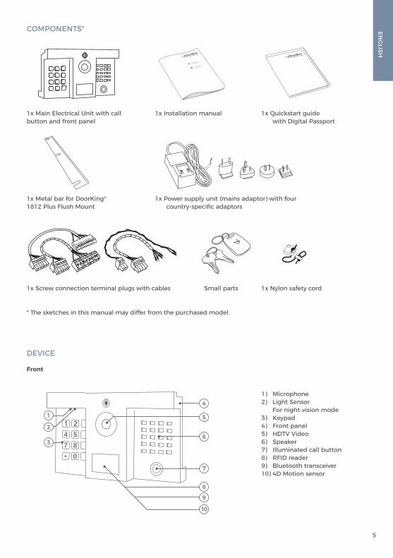
1x Metal bar for DoorKing®
1812 Plus Flush Mount1x Power supply unit (mains adaptor) with four country-specific adaptors
Small parts 1x Nylon safety cord 1x Screw connection terminal plugs with cables
1x Quickstart guide with Digital Passport
1x Installation manual1x Main Electrical Unit with call button and front panel
* The sketches in this manual may differ from the purchased model.
COMPONENTS*
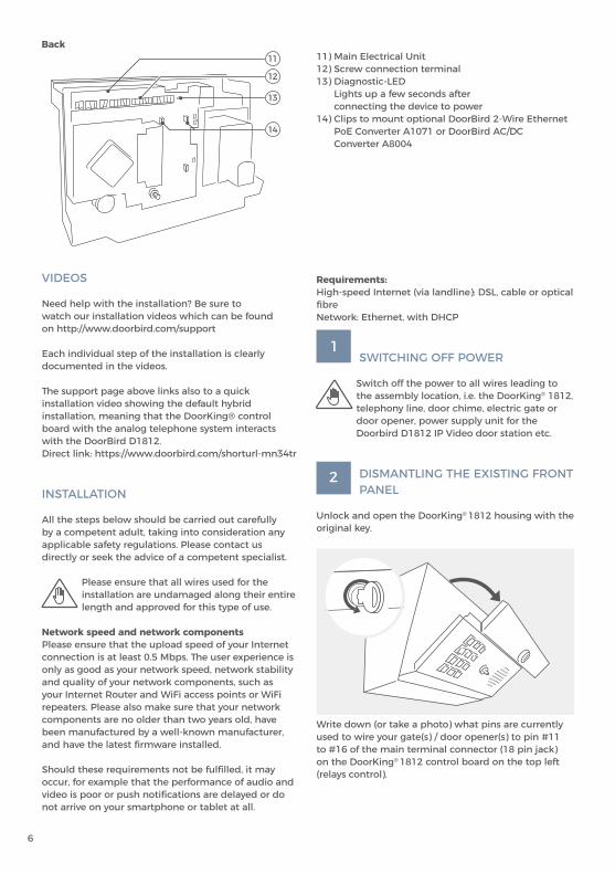
DEVICE
Front
4
5
6
7
9
10
1
2
3
1) Microphone2) Light Sensor For night-vision mode 3) Keypad4) Front panel5) HDTV Video6) Speaker 7) Illuminated call button8) RFID reader9) Bluetooth transceiver 10) 4D Motion sensor
8
6
VIDEOS
Need help with the installation? Be sure to watch our installation videos which can be found on http://www.doorbird.com/support
Each individual step of the installation is clearly documented in the videos.
The support page above links also to a quick installation video showing the default hybrid installation, meaning that the DoorKing® control board with the analog telephone system interacts with the DoorBird D1812. Direct link: https://www.doorbird.com/shorturl-mn34tr
INSTALLATION
All the steps below should be carried out carefully by a competent adult, taking into consideration any applicable safety regulations. Please contact us directly or seek the advice of a competent specialist.
Please ensure that all wires used for the installation are undamaged along their entire length and approved for this type of use.
Network speed and network componentsPlease ensure that the upload speed of your Internet connection is at least 0.5 Mbps. The user experience is only as good as your network speed, network stability and quality of your network components, such as your Internet Router and WiFi access points or WiFi repeaters. Please also make sure that your network components are no older than two years old, have been manufactured by a well-known manufacturer, and have the latest firmware installed.
Should these requirements not be fulfilled, it may occur, for example that the performance of audio and video is poor or push notifications are delayed or do not arrive on your smartphone or tablet at all.
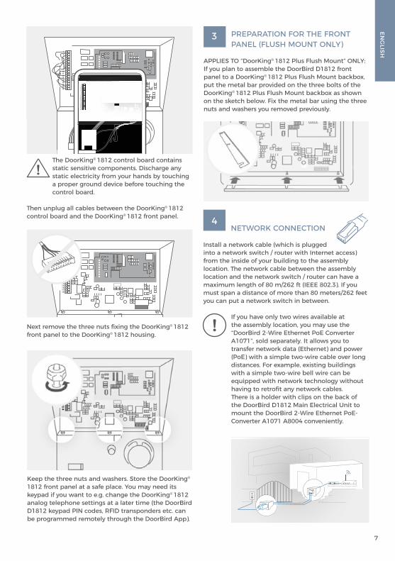
Back11) Main Electrical Unit12) Screw connection terminal13) Diagnostic-LED Lights up a few seconds after connecting the device to power14) Clips to mount optional DoorBird 2-Wire Ethernet PoE Converter A1071 or DoorBird AC/DC Converter A8004
Write down (or take a photo) what pins are currently used to wire your gate(s) / door opener(s) to pin #11 to #16 of the main terminal connector (18 pin jack) on the DoorKing® 1812 control board on the top left (relays control).
Requirements:High-speed Internet (via landline): DSL, cable or optical fibreNetwork: Ethernet, with DHCP
1SWITCHING OFF POWER
Switch off the power to all wires leading to the assembly location, i.e. the DoorKing® 1812, telephony line, door chime, electric gate or door opener, power supply unit for the Doorbird D1812 IP Video door station etc.
2 DISMANTLING THE EXISTING FRONT PANEL
Unlock and open the DoorKing® 1812 housing with the original key.
14
11
12
13
ENG
LISH
7
4 NETWORK CONNECTION
Install a network cable (which is plugged into a network switch / router with Internet access) from the inside of your building to the assembly location. The network cable between the assembly location and the network switch / router can have a maximum length of 80 m/262 ft (IEEE 802.3). If you must span a distance of more than 80 meters/262 feet you can put a network switch in between.
If you have only two wires available at the assembly location, you may use the “DoorBird 2-Wire Ethernet PoE Converter A1071”, sold separately. It allows you to transfer network data (Ethernet) and power (PoE) with a simple two-wire cable over long distances. For example, existing buildings with a simple two-wire bell wire can be equipped with network technology without having to retrofit any network cables.There is a holder with clips on the back of the DoorBird D1812 Main Electrical Unit to mount the DoorBird 2-Wire Ethernet PoE-Converter A1071 A8004 conveniently.
Next remove the three nuts fixing the DoorKing® 1812 front panel to the DoorKing® 1812 housing.
Keep the three nuts and washers. Store the DoorKing®
1812 front panel at a safe place. You may need its keypad if you want to e.g. change the DoorKing® 1812 analog telephone settings at a later time (the DoorBird D1812 keypad PIN codes, RFID transponders etc. can be programmed remotely through the DoorBird App).
3 PREPARATION FOR THE FRONT PANEL (FLUSH MOUNT ONLY)
APPLIES TO “DoorKing® 1812 Plus Flush Mount” ONLY: If you plan to assemble the DoorBird D1812 front panel to a DoorKing® 1812 Plus Flush Mount backbox, put the metal bar provided on the three bolts of the DoorKing® 1812 Plus Flush Mount backbox as shown on the sketch below. Fix the metal bar using the three nuts and washers you removed previously.
123456789
101112131415161718
123456789
101112131415161718
123456789
101112131415161718
The DoorKing® 1812 control board contains static sensitive components. Discharge any static electricity from your hands by touching a proper ground device before touching the control board.
Then unplug all cables between the DoorKing® 1812 control board and the DoorKing® 1812 front panel.

8
5 PREPARE POWER SUPPLY
OPTION 2Power supply and network connection using PoE (Power over Ethernet)
To power the device via a PoE-Switch (e.g. D-Link DGS-1008P) or PoE-Injector (e.g. DoorBird Gigabit PoE Injector A1091), use a CAT.5 cable or higher in accordance with the PoE standard IEEE 802.3af Mode A.
A CAT.5 cable or higher must be used for this purpose, as network signals can only be transmitted over completely insulated, shielded and twisted cables. If you use PoE as a source of power, the four wires for PoE then simultaneously form the data line. The device will not start if your PoE-Switch/PoE-Injector does not support the PoE Standard IEEE 802.3af Mode A.
If you must power more than one device with one power supply , we recommend to use a PoE-Switch with PoE Standard IEEE 802.3af Mode A or an appropriate DIN rail power supply (see “OPTION 3”).
Theoretically (not recommended by us!), an unshielded, but over the whole length (max. 80 m/262 ft) twisted bell wire with two pairs of wires (first twisted pair of wires: “T+, T-”, second twisted pair of wires “R+, R-”) can be used for the network and PoE transmission as an alternative to a Cat.5 network cable or better. This is comparable to a Cat.3 network cable. In this case, however, we cannot guarantee the data throughput or the stability of the network connection and power supply; this must be measured and checked on site by qualified personnel over several hours (network data is transmitted at high frequency, therefore a shielded Cat.5 network cable twisted in pairs or better must normally be used).
NOTICE Do not combine the power supply from the power supply unit (mains adaptor) with the power supply via PoE.
You can find further information about PoE here: http://www.doorbird.com/poe
1. Disconnect the PoE-Switch or PoE-Injector from the power grid.2. Place the network cable in the installation site of the device.
OPTION 1 Power supply using the power supply unit (mains adaptor)
To power the device using the provided mains adapter, 2 insulated wires are required. The power supply unit has a 300 cm (9.8 ft) long cable with two insulated wires. The network connection is then established via a network cable.
The provided mains adaptor is only capable to power one device. It is not designed to power multiple devices simultaneously.
If you must power more than one device with one power supply, we recommend to use a PoE-Switch with PoE Standard IEEE 802.3af Mode A or an appropriate DIN rail power supply (see “OPTION 3”).
NOTICE Do not plug the power supply unit into the wall socket yet.
Only use the power supply unit provided along with the device, or a DIN-rail power supply unit (see “OPTION 3”) that you can obtain from us separately, since this has been specially stabilized electrically and is equipped with an integrated audio interference reduction device. Other power supply units may destroy the device or cause poor transmission quality. The warranty automatically expires if you use a different power supply unit.
The power supply unit is plugged into a wall socket inside your house (Step 10), usually where the two wires from your assembly location come out of the wall in the interior of the house.
The provided mains adapter is not outdoor-ready, it is for indoor-use only.
The DoorBird D1812 is not powered via the DoorKing® 1812 power supply. It requires a separate power supply via PoE or 12-15 VDC (15 VDC power supply unit in scope of delivery).
ENG
LISH
9
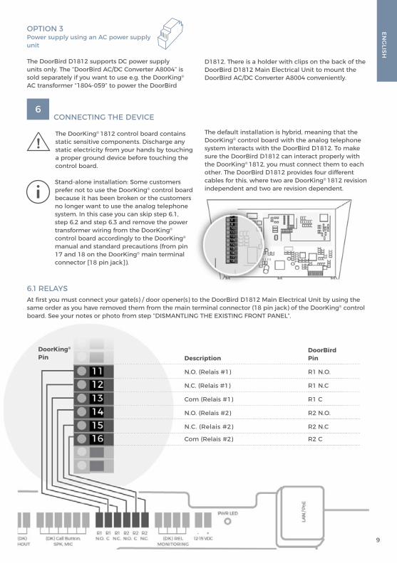
OPTION 3Power supply using an AC power supply unit
The DoorBird D1812 supports DC power supply units only. The “DoorBird AC/DC Converter A8004” is sold separately if you want to use e.g. the DoorKing® AC transformer “1804‐059” to power the DoorBird
6.1 RELAYSAt first you must connect your gate(s) / door opener(s) to the DoorBird D1812 Main Electrical Unit by using the same order as you have removed them from the main terminal connector (18 pin jack) of the DoorKing® control board. See your notes or photo from step “DISMANTLING THE EXISTING FRONT PANEL”.
DoorBird Pin
R1 N.O.
R1 N.C
R1 C
R2 N.O.
R2 N.C
R2 C
Description
N.O. (Relais #1)
N.C. (Relais #1)
Com (Relais #1)
N.O. (Relais #2)
N.C. (Relais #2)
Com (Relais #2)
DoorKing®
Pin
D1812. There is a holder with clips on the back of the DoorBird D1812 Main Electrical Unit to mount the DoorBird AC/DC Converter A8004 conveniently.
6 CONNECTING THE DEVICE
The DoorKing® 1812 control board contains static sensitive components. Discharge any static electricity from your hands by touching a proper ground device before touching the control board.
Stand-alone installation: Some customers prefer not to use the DoorKing® control board because it has been broken or the customers no longer want to use the analog telephone system. In this case you can skip step 6.1, step 6.2 and step 6.3 and remove the power transformer wiring from the DoorKing® control board accordingly to the DoorKing® manual and standard precautions (from pin 17 and 18 on the DoorKing® main terminal connector [18 pin jack]).
The default installation is hybrid, meaning that the DoorKing® control board with the analog telephone system interacts with the DoorBird D1812. To make sure the DoorBird D1812 can interact properly with the DoorKing® 1812, you must connect them to each other. The DoorBird D1812 provides four different cables for this, where two are DoorKing® 1812 revision independent and two are revision dependent.
10
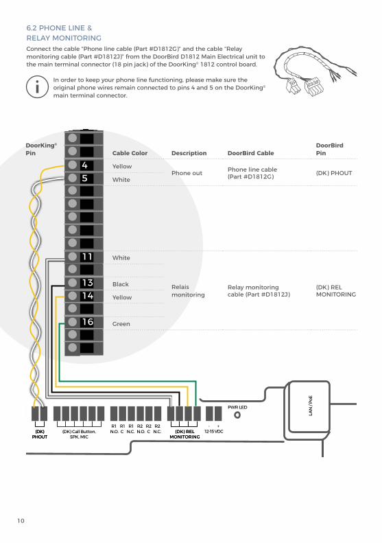
6.2 PHONE LINE & RELAY MONITORINGConnect the cable “Phone line cable (Part #D1812G)” and the cable “Relay monitoring cable (Part #D1812J)” from the DoorBird D1812 Main Electrical unit to the main terminal connector (18 pin jack) of the DoorKing® 1812 control board.
In order to keep your phone line functioning, please make sure the original phone wires remain connected to pins 4 and 5 on the DoorKing®
main terminal connector.
Cable Color Description DoorBird CableDoorBird Pin
YellowPhone out Phone line cable
(Part #D1812G) (DK) PHOUTWhite
White
Relais monitoring
Relay monitoring cable (Part #D1812J)
(DK) REL MONITORING
Black
Yellow
Green
DoorKing®
Pin
E1 E1 GND D1 D0WIEGAND
R1 R1 R1 R2 R2 R2 - +12-15 VDC(DK)
PHOUT(DK) Call Button,
SPK, MIC(DK) REL
MONITORINGN.O. C N.C. N.O. C N.C.
LightMIC Sensor
PWR LED
123456789101112131415161718
E1 E1 GND D1 D0WIEGAND
R1 R1 R1 R2 R2 R2 - +12-15 VDC(DK)
PHOUT(DK) Call Button,
SPK, MIC(DK) REL
MONITORINGN.O. C N.C. N.O. C N.C.
LightMIC Sensor
PWR LED
123456789101112131415161718
123456789101112131415161718
123456789101112131415161718
E1 E1 GND D1 D0WIEGAND
R1 R1 R1 R2 R2 R2 - +12-15 VDC(DK)
PHOUT(DK) Call Button,
SPK, MIC(DK) REL
MONITORINGN.O. C N.C. N.O. C N.C.
LightMIC Sensor
PWR LED

ENG
LISH
11
123456789
101112131415161718
E1 E1 GND D1 D0WIEGAND
R1 R1 R1 R2 R2 R2 - +12-15 VDC(DK)
PHOUT(DK) Call Button,
SPK, MIC(DK) REL
MONITORINGN.O. C N.C. N.O. C N.C.
LightMIC Sensor
PWR LED
E1 E1 GND D1 D0WIEGAND
R1 R1 R1 R2 R2 R2 - +12-15 VDC(DK)
PHOUT(DK) Call Button,
SPK, MIC(DK) REL
MONITORINGN.O. C N.C. N.O. C N.C.
LightMIC Sensor
PWR LED
6.3 INTERFACE CABLEFor the next step you must determine the revision of the DoorKing® 1812 control board. You can find the revision written on a sticker or printed on the bottom right on the control board as marked in the drawing. It is either “1871-010” or “1970-010”. If you find a different revision, please contact us before continuing with the installation.
123456789101112131415161718
1970-010
123456789101112131415161718
1871-010
6.4 OTHER CABLES
It is possible to connect all other cables and wires to the device conveniently and safely via the labeled screw connection terminals. You can connect all necessary cables and wires to the device now.
Use the cable “Interface cable type A (Part #D1812H)” for revision “1871-010” and connect it to the white 8 pin jack on the bottom right of the DoorKing® 1812 control board.
Use the cable “Interface cable type B (Part #D1812I)” for revision “1970-010” and connect it to the black 8 pin jack on the bottom right of the DoorKing® 1812 control board.
For easier installation we strongly recommend to remove the plug from screw connection terminal while you connect the cables and wires.
NOTICEPlease remove any cables and wires from the connection ports of the device that you do not need.
123456789
101112131415161718
12
E1 E1 GND D1 D0WIEGAND
R1 R1 R1 R2 R2 R2 - +12-15 VDC(DK)
PHOUT(DK) Call Button,
SPK, MIC(DK) REL
MONITORINGN.O. C N.C. N.O. C N.C.
LightMIC Sensor
PWR LED
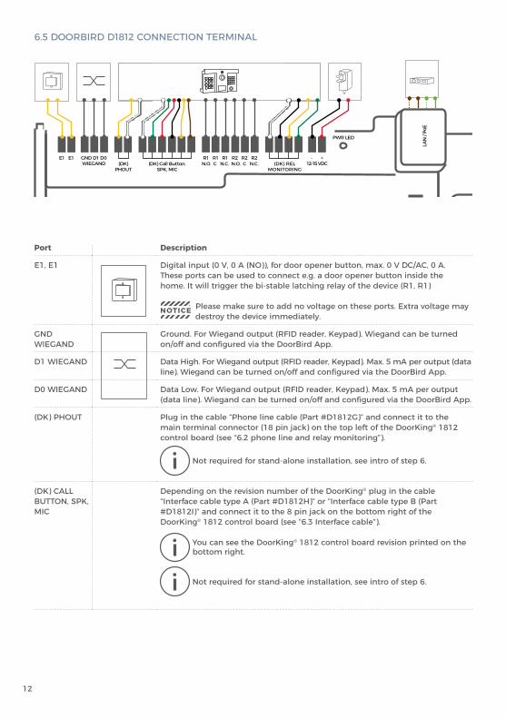
Port Description
E1, E1 Digital input (0 V, 0 A (NO)), for door opener button, max. 0 V DC/AC, 0 A. These ports can be used to connect e.g. a door opener button inside the home. It will trigger the bi-stable latching relay of the device (R1, R1)
NOTICE Please make sure to add no voltage on these ports. Extra voltage may destroy the device immediately.
GND WIEGAND
Ground. For Wiegand output (RFID reader, Keypad). Wiegand can be turned on/off and configured via the DoorBird App.
D1 WIEGAND Data High. For Wiegand output (RFID reader, Keypad). Max. 5 mA per output (data line). Wiegand can be turned on/off and configured via the DoorBird App.
D0 WIEGAND Data Low. For Wiegand output (RFID reader, Keypad). Max. 5 mA per output (data line). Wiegand can be turned on/off and configured via the DoorBird App.
(DK) PHOUT Plug in the cable “Phone line cable (Part #D1812G)” and connect it to the main terminal connector (18 pin jack) on the top left of the DoorKing® 1812 control board (see “6.2 phone line and relay monitoring”).
Not required for stand-alone installation, see intro of step 6.
(DK) CALL BUTTON, SPK, MIC
Depending on the revision number of the DoorKing® plug in the cable “Interface cable type A (Part #D1812H)” or “Interface cable type B (Part #D1812I)” and connect it to the 8 pin jack on the bottom right of the DoorKing® 1812 control board (see “6.3 Interface cable”).
You can see the DoorKing® 1812 control board revision printed on the bottom right.
Not required for stand-alone installation, see intro of step 6.
6.5 DOORBIRD D1812 CONNECTION TERMINAL
ENG
LISH
13
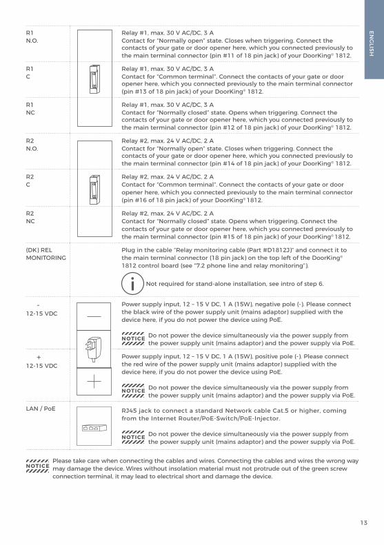
R1 N.O.
Relay #1, max. 30 V AC/DC, 3 AContact for “Normally open” state. Closes when triggering. Connect the contacts of your gate or door opener here, which you connected previously to the main terminal connector (pin #11 of 18 pin jack) of your DoorKing® 1812.
R1C
Relay #1, max. 30 V AC/DC, 3 AContact for “Common terminal”. Connect the contacts of your gate or door opener here, which you connected previously to the main terminal connector (pin #13 of 18 pin jack) of your DoorKing® 1812.
R1NC
Relay #1, max. 30 V AC/DC, 3 AContact for “Normally closed” state. Opens when triggering. Connect the contacts of your gate or door opener here, which you connected previously to the main terminal connector (pin #12 of 18 pin jack) of your DoorKing® 1812.
R2N.O.
Relay #2, max. 24 V AC/DC, 2 AContact for “Normally open” state. Closes when triggering. Connect the contacts of your gate or door opener here, which you connected previously to the main terminal connector (pin #14 of 18 pin jack) of your DoorKing® 1812.
R2C
Relay #2, max. 24 V AC/DC, 2 AContact for “Common terminal”. Connect the contacts of your gate or door opener here, which you connected previously to the main terminal connector (pin #16 of 18 pin jack) of your DoorKing® 1812.
R2NC
Relay #2, max. 24 V AC/DC, 2 AContact for “Normally closed” state. Opens when triggering. Connect the contacts of your gate or door opener here, which you connected previously to the main terminal connector (pin #15 of 18 pin jack) of your DoorKing® 1812.
(DK) REL MONITORING
Plug in the cable “Relay monitoring cable (Part #D1812J)” and connect it to the main terminal connector (18 pin jack) on the top left of the DoorKing®
1812 control board (see “7.2 phone line and relay monitoring”).
Not required for stand-alone installation, see intro of step 6.
-12-15 VDC
Power supply input, 12 – 15 V DC, 1 A (15W), negative pole (-). Please connect the black wire of the power supply unit (mains adaptor) supplied with the device here, if you do not power the device using PoE.
NOTICE Do not power the device simultaneously via the power supply from the power supply unit (mains adaptor) and the power supply via PoE.
+12-15 VDC
Power supply input, 12 – 15 V DC, 1 A (15W), positive pole (-). Please connect the red wire of the power supply unit (mains adaptor) supplied with the device here, if you do not power the device using PoE.
NOTICE Do not power the device simultaneously via the power supply from the power supply unit (mains adaptor) and the power supply via PoE.
LAN / PoE RJ45 jack to connect a standard Network cable Cat.5 or higher, coming from the Internet Router/PoE-Switch/PoE-Injector.
NOTICE Do not power the device simultaneously via the power supply from the power supply unit (mains adaptor) and the power supply via PoE.
NOTICEPlease take care when connecting the cables and wires. Connecting the cables and wires the wrong way may damage the device. Wires without insolation material must not protrude out of the green screw connection terminal, it may lead to electrical short and damage the device.
14
8 ACTIVATE THE DEVICE
Switch on the power to all wires leading to the assembly location and to your DoorKing® 1812 control board.
If the device is to be supplied with power by a mains adapter, plug the power adapter of the device into a wall socket. If the device is to be powered via PoE, switch on the PoE-Switch/ PoE-Injector which is connected to the device. If the device is to be powered via DIN-rail power supply, switch on the DIN-rail power supply.
The Diagnostic-LED indicates whether the device is supplied with power. This LED lights up in blue color a few seconds after you have connected the device to the power supply. The device is now ready for operation. If the Diagnostic LED does not light up, please check the power supply. When using a wall plug power supply and not PoE please check whether you have connected the positive pole and negative pole to the device correctly. The device is ready for operation (booting up process, any software updates, etc.) once it has emitted a short diagnosis sound from the integrated loudspeaker. This may last for up to 5 minutes.
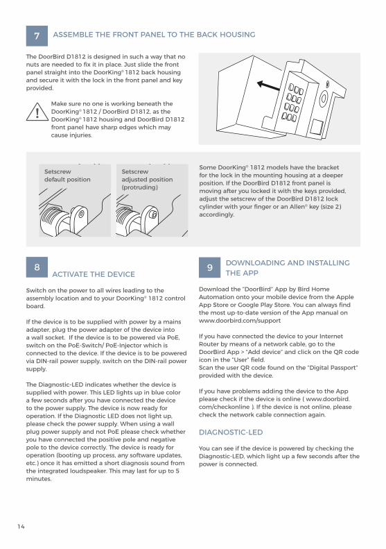
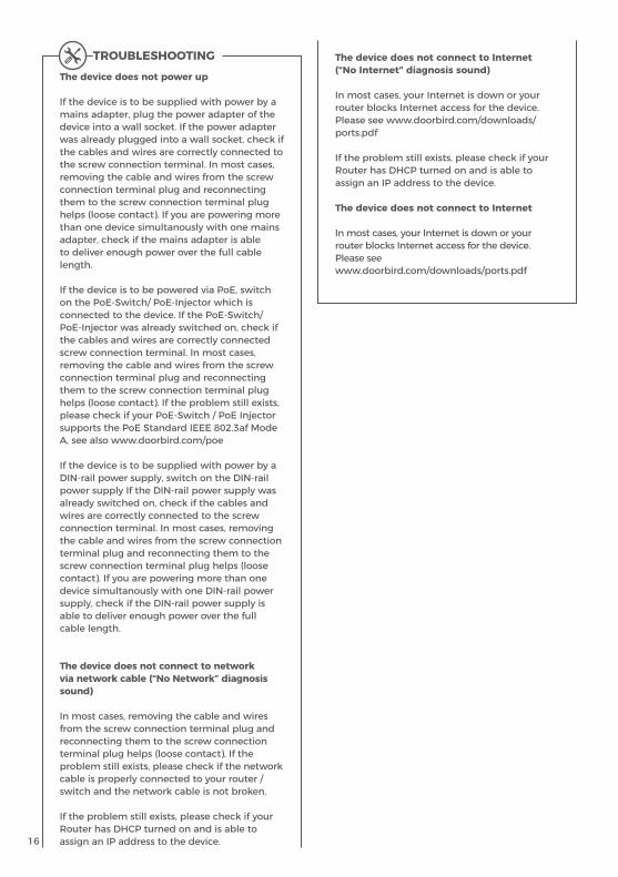
Some DoorKing® 1812 models have the bracket for the lock in the mounting housing at a deeper position. If the DoorBird D1812 front panel is moving after you locked it with the keys provided, adjust the setscrew of the DoorBird D1812 lock cylinder with your finger or an Allen® key (size 2) accordingly.
Setscrew default position
Setscrew adjusted position(protruding)
9 DOWNLOADING AND INSTALLING THE APP
Download the “DoorBird” App by Bird Home Automation onto your mobile device from the Apple App Store or Google Play Store. You can always find the most up-to-date version of the App manual on www.doorbird.com/support
If you have connected the device to your Internet Router by means of a network cable, go to the DoorBird App > “Add device” and click on the QR code icon in the “User” field. Scan the user QR code found on the “Digital Passport” provided with the device.
If you have problems adding the device to the App please check if the device is online ( www.doorbird. com/checkonline ). If the device is not online, please check the network cable connection again.
DIAGNOSTIC-LED
You can see if the device is powered by checking the Diagnostic-LED, which light up a few seconds after the power is connected.
7 ASSEMBLE THE FRONT PANEL TO THE BACK HOUSING
The DoorBird D1812 is designed in such a way that no nuts are needed to fix it in place. Just slide the front panel straight into the DoorKing® 1812 back housing and secure it with the lock in the front panel and key provided.
Make sure no one is working beneath the DoorKing® 1812 / DoorBird D1812, as the DoorKing® 1812 housing and DoorBird D1812 front panel have sharp edges which may cause injuries.

ENG
LISH
15
CONFIGURE THE SPEAKER AND MICROPHONE
You can configure the speaker and microphone volume using the potentiometer on the DoorKing® 1812 control board. Please see the manual of your DoorKing® 1812 how to do this (https://www.doorking.com/product-documents-and-downloads). Normally you can leave this at the DoorKing® 1812 default settings.
DIAGNOSTIC-SOUNDS
After around one minute, the device emits brief diagnostic sounds after it has been connected to power supply / network / internet.
LENS
The product uses a straightened Wide-Eye hemispheric lens (HD). Due to the wide angle of coverage (horizontal, vertical, diagonal), a small edge may appear in the corners of the image as well as reflections in the image from the surface of the front of the unit.
Recommended lens installation height: 145 cm (4 ft).
MOTION SENSOR
The device has a built-in Motion Sensor with 4D Technology. You can use it for numerous applications, e. g. to send an alarm to a mobile device or to switch a relay to turn on an outdoor light.
The adjustable distance is optimized for a 1.75m (69 in) tall 70kg (165 lbs) person in a free environment. The accuracy of the distance of the motion sensor can vary depending on the environment.
BLUETOOTH TRANSCEIVER
The device has a built-in Bluetooth® transceiver. We will add further functionality for interesting applications soon. Please check our company news blog or the latest version of this manual at www.doorbird.com/support for updates.
API
The device features a well documented API for third-party integration. For information, terms and conditions see www.doorbird.com/api
DOORBIRD CONNECT
The device features many options to integrate it into third-party applications. For information, terms and conditions see www.doorbird.com/connect
MAINTENANCE OF THE FRONT PANEL
Cleaning and maintenance instructionsAll of our front panels are made of high-quality materials and are designed for a durable lifetime. Since door stations are usually installed in unprotected outdoor areas, they are exposed to adverse weather conditions and aggressive substances, especially close to frequently used roads, in coastal and industrial areas. Therefore, please consider the following care instructions. Unfortunately, we cannot accept any liability for damage if these instructions are not being observed. Aggressive dirt such as bird droppings should be removed as quickly as possible.
NOTICEAggressive stains such as bird droppings should be removed as soon as possible.
NOTICENever use abrasive detergents such as steel wool or scouring milk!
Warm water is usually sufficient, if necessary with a little detergent, a soft cloth or brush. Plastic parts (camera or name tags) must not be treated with metal care products. Remove all residues of cleaning agents or lubricants to avoid stains or discolouration after the maintenance.
Stainless SteelOnly high-quality stainless steel is used for all available DoorBird door stations. However, high-quality stainless steel can also rust, as approx. 70 % of stainless steel is made of iron. Rust resistance is only achieved by a protective layer (also called passive layer), which covers the iron like a skin. This protective layer consists essentially of chromium and other precious metals.
Iron particles, grinding dust and chips deposited on stainless steel can lead to corrosion (rust film). These iron particles can be found everywhere, but especially in coastal and industrial areas and close to frequently used roads. Please remove ferrous deposits immediately, as they will attack your door station and lead to real rust if not removed. To remove rust, simply wipe off the dust; in addition, a care product is recommended, e.g. WD 40, available e.g. at Amazon for less than € 5.00. Simply apply in a thin layer and rub in. The same applies if rust appears on the engravings on the stainless steel surface.
Cement or lime splashes should be carefully removed as soon as possible with a wooden spatula before hardening.
The following cleaning detergents are not to be used as they reduce corrosion resistance:• products containing chloride and hydrochloric acid• Bleach (in case of accidental use, rinse thoroughly with water)• Silver polish
After the cleaning with clear water wipe with damp
16
The device does not power up
If the device is to be supplied with power by a mains adapter, plug the power adapter of the device into a wall socket. If the power adapter was already plugged into a wall socket, check if the cables and wires are correctly connected to the screw connection terminal. In most cases, removing the cable and wires from the screw connection terminal plug and reconnecting them to the screw connection terminal plug helps (loose contact). If you are powering more than one device simultanously with one mains adapter, check if the mains adapter is able to deliver enough power over the full cable length.
If the device is to be powered via PoE, switch on the PoE-Switch/ PoE-Injector which is connected to the device. If the PoE-Switch/ PoE-Injector was already switched on, check if the cables and wires are correctly connected screw connection terminal. In most cases, removing the cable and wires from the screw connection terminal plug and reconnecting them to the screw connection terminal plug helps (loose contact). If the problem still exists, please check if your PoE-Switch / PoE Injector supports the PoE Standard IEEE 802.3af Mode A, see also www.doorbird.com/poe
If the device is to be supplied with power by a DIN-rail power supply, switch on the DIN-rail power supply If the DIN-rail power supply was already switched on, check if the cables and wires are correctly connected to the screw connection terminal. In most cases, removing the cable and wires from the screw connection terminal plug and reconnecting them to the screw connection terminal plug helps (loose contact). If you are powering more than one device simultanously with one DIN-rail power supply, check if the DIN-rail power supply is able to deliver enough power over the full cable length.
The device does not connect to network via network cable (“No Network” diagnosis sound)
In most cases, removing the cable and wires from the screw connection terminal plug and reconnecting them to the screw connection terminal plug helps (loose contact). If the problem still exists, please check if the network cable is properly connected to your router / switch and the network cable is not broken.
If the problem still exists, please check if your Router has DHCP turned on and is able to assign an IP address to the device.
TROUBLESHOOTING The device does not connect to Internet (“No Internet” diagnosis sound)
In most cases, your Internet is down or your router blocks Internet access for the device. Please see www.doorbird.com/downloads/ ports.pdf
If the problem still exists, please check if your Router has DHCP turned on and is able to assign an IP address to the device.
The device does not connect to Internet
In most cases, your Internet is down or your router blocks Internet access for the device. Please see www.doorbird.com/downloads/ports.pdf
ENG
LISH
17
LEGAL NOTESGeneral remarks1. DoorBird is a registered trademark of Bird Home Automation
GmbH.
2. Apple, the Apple logo, Mac, Mac OS, Macintosh, iPad, Multi-Touch, iOS, iPhone and iPod touch are trademarks of Apple Inc.
3. Google, Android and Google Play are trademarks of Google, Inc.
4. The Bluetooth® word mark and logos are registered trademarks of Bluetooth SIG, Inc.
5. DoorKing® is trademark of DoorKing, Inc.
6. All other company and product names may be trademarks of the respective companies with which they are associated.
7. We reserve the right to make changes to our products in the interests of technical advancement. The products shown may also look different from the products supplied based on ongoing enhancement.
8. Reproducing or using texts, illustrations and photos from this instruction manual in any media – even if only in the form of excerpts – shall only be permitted with our express written consent.
9. The design of this manual is subject to copyright protection. We do not accept any liability for any errors or any erroneous content or printing errors (even in the case of technical specifications or within graphics and technical sketches).
10. Our products are in compliance with all technical guidelines, electrical and telecommunications regulations applicable in Germany, the EU and the USA.
11. Our products and also the components contained therein (ICs, software, etc.) may only be used for civilian non-military purposes.
Data privacy and data security1. For maximum security, the device uses the same encryption
technologies as are used in online banking. For your security, no port forwarding or DynDNS is used either.
2. The data centre location for remote access over the Internet by means of an App is obligatory in the EU if the determined Internet IP-Address location of the device is within the EU. The data centre is operated in line with the most stringent security standards.
3. Video, audio and any other surveillance methods can be regulated by laws that vary from country to country. Check the laws in your local region before installing and using this device for surveillance purposes.
If the device is a door-, indoor station or camera: • In many countries video and voice signal may only be transmitted
once a visitor has rung the bell (data privacy, configurable in the App).
• Please carry out the mounting in such a way that the detection range of the camera limits the device exclusively to the immediate entrance area.
• The device may come with a visitor history and motion sensor. You can activate/deactivate this function if required.
If necessary, indicate the presence of the device in a suitable place and in a suitable form.
Please observe any relevant country-specific statutory regulations concerning the use of surveillance components and surveillance cameras applicable at the installation site.
Check with the property owner and your house community if you are allowed to install and use this product. Bird Home Automation GmbH cannot be held responsible for any miss-use or miss-configuration of this product, including the unauthorized opening of a door.
Bird Home Automation cannot be held responsible for damages caused by improper existing installations or improper installation.
Software and operating system’s updates (so-called “firmware updates”) are generally automatically installed on the products of Bird Home Automation GmbH via Internet, if technically possible. Automatic firmware updates keep the products‘ software up to date so that they always work reliably, safely and efficiently. Through further development, features can be added, extended or slightly changed. Major changes or limitations to existing features will generally occur if Bird Home Automation GmbH deems it necessary (e.g. for data protection, data security or stability reasons, or to keep them up to date). When a firmware update is available, Bird Home Automation GmbH‘s servers generally automatically distribute it to all compatible products connected to the Internet or Bird Home
Automation GmbH‘s servers. This process is gradual and can take several weeks. As soon as a product receives a firmware update, the system will be installed and will restart by itself. Installed firmware updates cannot be undone. Since the products and software of Bird Home Automation GmbH are not explicitly customer-specific products, a customer cannot deny an automatic update if the product is connected to the Internet or to the Bird Home Automation GmbH’s server.
PublisherBird Home Automation GmbHUhlandstraße 16510719 BerlinGermany
Web: www.doorbird.comEmail: [email protected]
It is possible that these manual still contains typographical errors or printing errors.The information in this manual will be checked regularly and corrections will be made in the next version. We accept no liability for errors of a technical or printing nature and their consequences.

18
Space for notes / Platz für Notizen


www.doorbird.com


