110
Energy Carriers for Powertrains < for a clean and efficient mobility > Status: Final for publication Version: 1.0 Date: 27.02.2014 ERTRAC Working Group: Energy and Environment NGVA Europe
Energy Carriers for Powertrains < for a clean and efficient mobility >
Status: Final for publication
Version: 1.0
Date: 27.02.2014
ERTRAC Working Group: Energy and Environment
NGVA Europe

www.ertrac.org
Page 2 of 110
Table of contents
Table of contents .............................................................................. 2
1 Executive Summary ............................................................ 4
2 Introduction ......................................................................... 7
3 Benefits and challenges ................................................... 11
4 Future energy carriers for mobility and derived infrastructure and powertrain implication....................... 14
4.1 Today’s energy carriers for mobility ..............................................................14 4.1.1 Fossil situation (reserves, resources) .............................................................. 16 4.1.2 ‘First generation’ / ‘State of the art’ biofuels ..................................................... 21 4.1.3 State of the art infrastructure ........................................................................... 25
4.2 Renewable Electricity ...................................................................................28
4.3 Biomass availability / Feedstock ...................................................................30
4.4 Renewable liquid fuels ..................................................................................36 4.4.1 Hydro treated (vegetable) oils and fats (HVO) and Hydrotreated Esters
(HEFA) ............................................................................................................ 36 4.4.2 Biomass to liquid (BtL) ..................................................................................... 38 4.4.3 Dimethyl Ether (DME) ...................................................................................... 40 4.4.4 Sugar to Diesel ................................................................................................ 42 4.4.5 Advanced sugar to Ethanol (or higher alcohols) pathways ............................... 44 4.4.6 Algae to liquid technologies ............................................................................. 44 4.4.7 Biotechnological fuel production ...................................................................... 46 4.4.8 Fuels from power-to-liquid ............................................................................... 48 4.4.9 Methyl-tertiary-butyl ether (MTBE) and Methanol ............................................ 51 4.4.10 Tailor made fuels from biomass (TMFB) .......................................................... 52 4.4.11 Liquid Air ......................................................................................................... 55
4.5 Renewable gaseous fuels.............................................................................56 4.5.1 Bio / Algae Methane (CH4) via biogas .............................................................. 56 4.5.2 Gaseous fuels from power-to-gas .................................................................... 58 4.5.3 Renewable hydrogen ....................................................................................... 60 4.5.4 Solar to gas ..................................................................................................... 61
4.6 Powertrains adaption caused by alternative fuels / energies ........................62 4.6.1 Diesel combustion system ............................................................................... 63 4.6.2 Gasoline combustion system ........................................................................... 66
www.ertrac.org
Page 3 of 110
4.6.3 Gas and Dual Fuel combustion systems .......................................................... 72 4.6.4 Fuel cell vehicles (FCEV) ................................................................................ 79 4.6.5 Battery electric vehicles (BEV)......................................................................... 80 4.6.6 Hybrid demands .............................................................................................. 80 4.6.7 Conclusion ...................................................................................................... 82
4.7 Future infrastructure .....................................................................................83 4.7.1 Infrastructure for diesel and gasoline fuels ...................................................... 83 4.7.2 Infrastructure for gas ....................................................................................... 83 4.7.3 Infrastructure for electricity recharging ............................................................. 85 4.7.4 Infrastructure for Electric Road Systems .......................................................... 86
4.8 Competition assessment of renewable energy .............................................86 4.8.1 Well-to-Wheel Analysis of complex energy systems ........................................ 86 4.8.2 Competitive assessment.................................................................................. 90 4.8.3 Technological assessment of different pathways ............................................. 92 4.8.4 Technological assessment of powertrain requirements ................................... 93 4.8.5 Conclusions ..................................................................................................... 93
5 Milestones .......................................................................... 95
5.1 Start to decarbonised and clean mobility (2015) ...........................................95
5.2 Milestone 1: Rising of decarbonised vehicles (2025) - [Market 2028 - 2030] ............................................................................................................96
5.3 Milestone 2: Alternative vehicles dominate sales to approach 50% CO2 reduction (2035) - [Market 2038 - 2040] .......................................................97
5.4 Milestone 3: Decarbonized and clean road mobility to obtain 60% CO2 reduction (2050) - [Market 2050+] .................................................................98
6 Roadmaps and recommendations for energy carriers, powertrains and infrastructure ........................................ 99
6.1 Roadmaps for energy carriers ....................................................................100
6.2 Future infrastructure ...................................................................................103
6.3 Powertrains adaption for advanced energy carriers ...................................103
6.4 Conclusion ..................................................................................................105
7 References ....................................................................... 107

www.ertrac.org
Page 4 of 110
1 Executive Summary
Road transport is essential in providing personal mobility and supporting economic growth that is vital to European society. On the other hand side, road transport is today strongly dependent on crude oil for its energy supply, so that the combustion of transport fuels constitutes a 20 - 25% share of overall GHG emissions in industrialized countries. Moreover, transport demand is still increasing, resulting in the transport sector projected to have a growing share of total European GHG emissions in the future. The increasing demand for resource-limited fossil energy carriers and climate change concerns due to anthropogenic global greenhouse gas (GHG) emissions represent two major challenges for society in general and for mobility in particular.
While efficiency improvements in today’s vehicle propulsion systems are essential, the transition to renewable and decarbonized energy carriers for transport is also of great importance. To limit global warming to less than 2°C by the end of this century, global greenhouse gas emissions need to be halved by 2050 relative to 1990. To give room for growth to developing countries and in view of the larger contribution of industrialised countries to GHG emissions, the industrialised countries need to have reduced their GHG emissions in 2050 by 80% or more relative to the year 1990. The European Commission has committed itself to this goal. A vision on how to transport should contribute to this goal has been worked out in the recent whitepaper1, in which the European Commission has defined a sectorial target for transport of 60% reduction in 2050 relative to 1990. This relates to the total emissions from the European transport sector, including domestic aviation and inland shipping. The target applies to the direct GHG emissions to be attributed to the transport sector, according to ‘Intergovernmental Panel on Climate Change’ (IPCC) definitions, meaning that electricity, hydrogen and biofuels count as zero-emission energy carriers towards the target2.
Within the transport sector three main reduction routes are available that can contribute to meeting the target:
• Improving the energy efficiency of vehicles, specifically of internal combustion engine vehicles by more efficient engines and powertrains, weight reduction, improved aerodynamics and a range of other measures;
• Application of alternative, low CO2 energy carriers, such as electricity, hydrogen or synthetic methane from renewable sources, and gaseous and liquid biofuels;
1 COM(2011) 144 final, Roadmap to a Single European Transport Area – Towards a competitive and resource efficient transport system. 2 In the sectoral IPCC definition upstream (WTT) emissions for the production of energy carriers for transport are attributed to the energy sector and the agricultural sector (in case of biofuels).
www.ertrac.org
Page 5 of 110
• Behavioural measures including energy efficient driving styles, improved logistics and curbing the growth of travel demand.
Both electro mobility (pure electric vehicles, fuel cell vehicles and plug-in hybrid configurations) and advanced internal combustion engines (powered by advanced liquid or gaseous fuels) will play significant roles in achieving this target. The energy carriers for these vehicles will need to be produced increasingly from renewable, low-carbon energy sources.
This roadmap provides an overview of energy carriers and production routes that offer significant potential to contribute to decarbonisation of the transport system’s energy supply in view of the above 2050 target. For each of the options the state-of-the art and future R&D needs are identified. Based on the current understanding of the status and potential of various options, milestones are defined for development and implementation of various options resulting in a roadmap for research and development that is intended to provide useful input to the European Commission’s Horizon 2020 programme as well as the R&D strategies of industry and research organisations throughout Europe.
The ‘Clean Power for Transport Package’ (CPT) from the European Commission also provides direction for the development of alternative energies and associated infrastructure in each Member State. This initiative recently proposed by the EC’s DG MOVE has as its main objective the provision of a sufficient infrastructure network for alternative fuels. The main alternative fuels with a potential for decarbonisation considered by the CPT proposal for further infrastructure deployment are electricity, hydrogen, biofuels and methane (CNG and LNG).
Another document that helps to assess different alternative fuels and vehicles is the JRC-EUCAR-CONCAWE (JEC) Well-to-Wheels (WtW) Study3. This study provides data on WtW GHG emissions and primary energy consumption for different energy pathways to the 2020+ horizon applied to C-segment vehicles.
Using these and related information sources, this roadmap also provides perspective on several important policy issues in the context of future energy carriers for mobility:
• Revision of the ‘Fuel Quality Directive’ (FQD, 2009/30/EC) • Revision of the ‘Renewable Energy Directive’ (RED, 2009/28/EC), including the
‘Impact of Indirect Land Use Change’ (ILUC) • Future vehicle emission standards • Vehicle efficiency targets beyond 2020
Based on this analysis, this roadmap finds that the European targets to achieve a 60% reduction in CO2 emissions from transport by 2050 is challenging but realisable with two main fields of activity:
3 version 4 July 2013

www.ertrac.org
Page 6 of 110
• Development of alternative and decarbonised fuels and energy carriers • Higher powertrain efficiency leading to cleaner mobility and reduction in
resource demand
In order to reduce fossil energy demand, diversification of other energy carriers will continue and grow. The most important part of decarbonised energy in 2050 will come from ‘green’ electricity produced from renewable sources like wind, solar and hydroelectric. Electricity will be stored in battery electric or plug-in hybrid vehicles, which are fully integrated to the electricity grid. Because there is a need to store renewable electricity for later use, a surplus of ‘green’ electricity could be stored in batteries or could be converted via power-to-gas technology into synthetic methane (SNG), liquid fuels or hydrogen.
Until 2035 and beyond, liquid and gaseous biofuels are expected to replace up to 20% of fossil energy for road mobility. The overall potential is limited by the availability of sustainable biomass. In this sector the use of residues will dominate. For gasoline use, blend rates of alcohols will increase. For diesel use, drop-in components (e.g. ‘Hydrotreated vegetable oils’ (HVO), BtL diesel and sugar-to-diesel technologies) will be important.
These biofuels must, as a minimum, meet the quality expectations contained in the FQD and RED, but could also provide better properties for efficient combustion and finally lower emissions. If this can be achieved, engine and powertrain technology will be further optimised with these new fuel qualities, also compliant with CEN standards.
Replacing more than 20% of fossil energy with new biogenic fuels will require direct CO2 recycling, without the production of biomass on agricultural land. Technologies based on ‘CO2 + Sunlight’ to fuel are under research and offer a huge potential which should be exploited.
For gaseous fuels, there is no blending restriction on the use of bio methane and a second source for decarbonised methane is from power-to-gas technology to synthetic methane, also fully interoperable with existing natural gas infrastructures, refuelling and vehicle technologies. In today’s powertrains, up to 25% CO2 emissions can be saved by the use of natural gas (mainly the molecule methane, CH4), compared to gasoline. Until 2030, the market share of new natural gas vehicles may increase towards 10%; a European-wide refuelling infrastructure is essential in order to achieve this level. For long haul heavy-duty truck and corridor related applications, methane is expected to be an option as liquefied natural gas (LNG) on the TEN-T network.
This roadmap reflects the current situation of energy carriers for powertrains. Technologic, economic or political changes in the future might / will influence the prioritisation. Therefor this roadmap will be reviewed and updated in future.
www.ertrac.org
Page 7 of 110
2 Introduction
Energy supply, sustainability and affordability are key factors for a clean future mobility. This roadmap will describe technologies and pathways to achieve these goals for road mobility. Therefore two major fields of research need to be optimized in parallel:
• Pathways to the energy carriers (focus: decarbonisation) • Powertrain technologies (focus: efficiency)
In its new ‘Strategic Research Agenda’ (SRA), ERTRAC has addressed theses major societal challenges of transport.
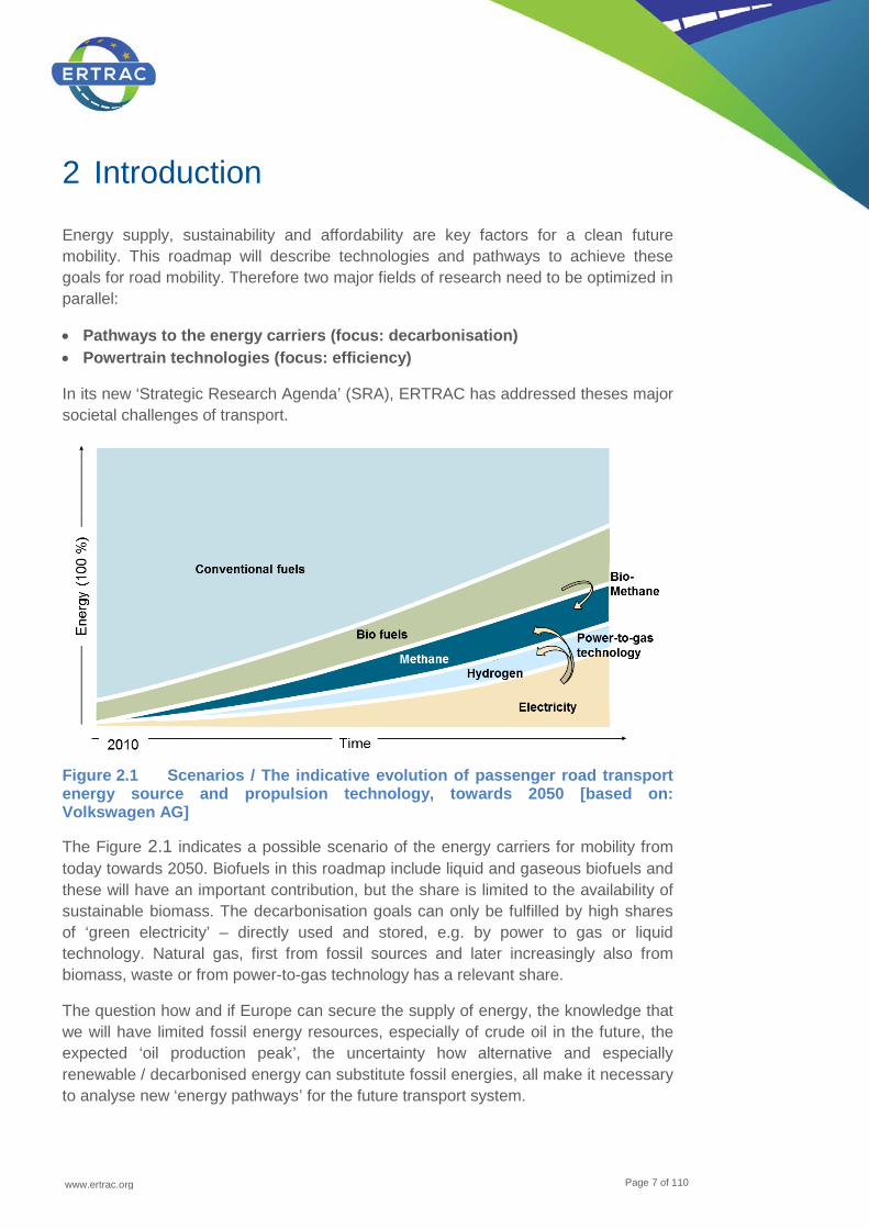
Figure 2.1 Scenarios / The indicative evolution of passenger road transport energy source and propulsion technology, towards 2050 [based on: Volkswagen AG]
The Figure 2.1 indicates a possible scenario of the energy carriers for mobility from today towards 2050. Biofuels in this roadmap include liquid and gaseous biofuels and these will have an important contribution, but the share is limited to the availability of sustainable biomass. The decarbonisation goals can only be fulfilled by high shares of ‘green electricity’ – directly used and stored, e.g. by power to gas or liquid technology. Natural gas, first from fossil sources and later increasingly also from biomass, waste or from power-to-gas technology has a relevant share.
The question how and if Europe can secure the supply of energy, the knowledge that we will have limited fossil energy resources, especially of crude oil in the future, the expected ‘oil production peak’, the uncertainty how alternative and especially renewable / decarbonised energy can substitute fossil energies, all make it necessary to analyse new ‘energy pathways’ for the future transport system.
www.ertrac.org
Page 8 of 110
In 2011 the European Commission published the White Paper on Transport4. Herein “Ten Goals for a competitive and resource efficient transport system: benchmarks for achieving the 60% GHG emission reduction target” in are defined in three sections:
• Developing and deploying new and sustainable fuels and propulsion systems • Optimising the performance of multimodal logistic chains, including by making
greater use of more energy-efficient modes • Increasing the efficiency of transport and of infrastructure use with information
systems and market-based incentives
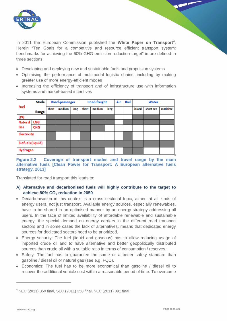
Figure 2.2 Coverage of transport modes and travel range by the main alternative fuels [Clean Power for Transport: A European alternative fuels strategy, 2013]
Translated for road transport this leads to:
A) Alternative and decarbonised fuels will highly contribute to the target to achieve 80% CO2 reduction in 2050
• Decarbonisation in this context is a cross sectorial topic, aimed at all kinds of energy users, not just transport. Available energy sources, especially renewables, have to be shared in an optimised manner by an energy strategy addressing all users. In the face of limited availability of affordable renewable and sustainable energy, the special demand on energy carriers in the different road transport sectors and in some cases the lack of alternatives, means that dedicated energy sources for dedicated sectors need to be prioritized.
• Energy security: The fuel (liquid and gaseous) has to allow reducing usage of imported crude oil and to have alternative and better geopolitically distributed sources than crude oil with a suitable ratio in terms of consumption / reserves.
• Safety: The fuel has to guarantee the same or a better safety standard than gasoline / diesel oil or natural gas (see e.g. FQD).
• Economics: The fuel has to be more economical than gasoline / diesel oil to recover the additional vehicle cost within a reasonable period of time. To overcome
4 SEC (2011) 359 final, SEC (2011) 358 final, SEC (2011) 391 final

www.ertrac.org
Page 9 of 110
the ‘chicken-and-egg’ problem, reliable and binding European wide harmonized political boundary conditions need to be defined.
• Quality: The mainstream fuels will resemble current fuels (diesel oil and gasoline) and will consist of blends of fossil fuel with increasing amounts of biomass-derived / decarbonized components5. Biofuels (and blend components) have to fulfil at least the current standards of quality.
• Customer acceptance: The fuel has to comply with customer appeal comparable to conventional fuels in term of availability and handling (adequate number of refuelling stations per area and / or citizens).
• Energy consumption: The goal is to apply fuels / energy carriers which allow high efficient powertrains and reduce the energy consumption significantly with respect to current technology.
B) Higher powertrain efficiency leads to cleaner mobility and resource protection
• Well-to-Wheel energy consumption has to be reduced in comparison to the currently applied pathways (Diesel and gasoline from crude oil used in internal combustion engines). Pathways which lead to an increase of WtW energy consumption should be avoided.
• In order to realise sustainable mobility in Europe, both urban and long distance vehicles for road transport will have to become significantly more efficient by 2020+. Mostly this target will be achieved by improving engine and powertrain efficiency, by improving vehicle aerodynamics, by reducing vehicle weight, by enlarging CV-payloads, by logistic optimisation and by influencing driving patterns.
• Environmental benefits: Lower exhausts (i.e. CO, NOx, particulate matter (PM), ozone promoters) and lower acoustical emissions
• With the diversification of decarbonised energies, the powertrains systems need to be adapted and optimised.
• As a matter of fact the ‘Internal Combustion Engines’ (ICEs) have been on the marketplace for a long time and they will be still in place for at least two decades. Due to this conventional powertrains need to become thermodynamically more efficient.
• The combination of electrical components and internal combustion engines need (e.g. hybrids, Plug-In hybrids) to be optimised. New (electric) components need to be developed.
• Customer acceptance: New powertrain technologies have to fulfil the customer demands in terms of vehicle range and vehicle / engine performance
This roadmap So optimising the whole chain from the sustainable production of energy, the energy carriers and the energy distribution via the infrastructure and use will be one of the most challenging goals for the next decades.
5 Fuel Quality Directive 2009/30/EC
www.ertrac.org
Page 10 of 110
The goal of this joint ERTRAC and NGVA roadmap is to provide an overview of energy carriers and production routes that offer significant potential to contribute to decarbonisation of the transport system’s energy supply in the short, mid and long term. For each of the options the state-of-the art and future R&D needs are identified. Issues discussed for the different options include:
• Technology maturity • Number of possible feedstocks and the availability of resources • Complexity of the process in terms of the number of conversion steps (which has
an impact on the needed investment) • WtW GHG savings potential • Cost for developments • Concurrency to e.g. food, agricultural and bio mass • Compatibility with engine technologies and distribution infrastructures • The potential to reduce ILUC and the competition with food (specifically for
biofuels).
Based on the current understanding of the status and potential of various options, milestones are defined for development and implementation of various options for today and the years 2025, 2035 and 2050+. These milestones provide an indicative picture of how the various options discussed in the roadmap can be applied in different transport subsectors to contribute to achieve a sustainable mobility system in the longer term.
This results in a roadmap for research and development that is intended to provide useful input to the European Commission’s Horizon 2020 programme as well as the R&D strategies of industry and research organisations throughout Europe. This roadmap is directly linked to other ERTRAC roadmaps6.
6 Other related ERTRAC roadmaps:
• Working Group Urban Mobility: ‘Integrating the Urban Mobility System’ ‘European Bus System of the Future’
• Working Group Long Distance Freight Transport: ‘Sustainable Long Distance Freight Transport’
• Working Group Road Safety: ‘Safe Road Transport’ ‘Road User Behaviour & Expectations’
• Working Group Global Competitiveness ‘European Technology & Production Concepts for Electric Vehicles’
www.ertrac.org
Page 11 of 110
3 Benefits and challenges
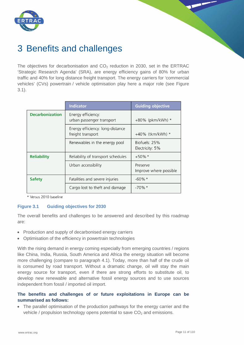
The objectives for decarbonisation and CO2 reduction in 2030, set in the ERTRAC ‘Strategic Research Agenda’ (SRA), are energy efficiency gains of 80% for urban traffic and 40% for long distance freight transport. The energy carriers for ‘commercial vehicles’ (CVs) powertrain / vehicle optimisation play here a major role (see Figure 3.1).
Figure 3.1 Guiding objectives for 2030
The overall benefits and challenges to be answered and described by this roadmap are:
• Production and supply of decarbonised energy carriers • Optimisation of the efficiency in powertrain technologies
With the rising demand in energy coming especially from emerging countries / regions like China, India, Russia, South America and Africa the energy situation will become more challenging (compare to paragraph 4.1). Today, more than half of the crude oil is consumed by road transport. Without a dramatic change, oil will stay the main energy source for transport, even if there are strong efforts to substitute oil, to develop new renewable and alternative fossil energy sources and to use sources independent from fossil / imported oil import.
The benefits and challenges of or future exploitations in Europe can be summarised as follows: • The parallel optimisation of the production pathways for the energy carrier and the
vehicle / propulsion technology opens potential to save CO2 and emissions.
www.ertrac.org
Page 12 of 110
• Identification of energy production and usage pathways which meet the given goals. Already the identification of not practical pathways will help.
• Advanced biofuels have a high potential to use residuals or ‘CO2 and sunlight’ as feedstocks in the future. Those fuels could achieve in future a very high quality and therefore the powertrain can become more efficient and clean.
• New combustion systems, optimised e.g. for hybrid or plug-in powertrains and enabled by e.g. heat recovery systems offers the potential to reach higher efficiencies.
• Drop-in type fuel will not require vehicle modifications or induce additional vehicle costs.
• For commercial vehicles (CV) new vehicle concepts adopting vehicle weight and / or dimensions enables higher payload efficiencies and reduces greenhouse emissions.
• The refuelling station infrastructure needs to become harmonised Europe-wide and able to fulfil customers’ demands.
• Harmonised fuel qualities and blend levels of bio components offer more cross European customer acceptance and the technical potential for further optimisation of powertrains. The engines can be optimised and adapted for the harmonised introduced qualities.
• Natural gas powertrains have not reached their theoretically achievable performance as today´s engines have the drawback of either being developed based on conventional gasoline-fuelled combustion engines or derived from diesel engines, and not designed and optimized for natural gas only. New dual fuel combustion concepts can moreover bring an additional gain in efficiency in the near future.
• Electric mobility with ‘battery electric vehicles’ (BEV) is for urban areas the most efficient and cleanest (locally) option for mobility. Moreover the integration in the flexible energy network will help to overcome the storage problem of volatile ‘green’ electricity. Surplus of ‘green’ electricity can be stored in automotive batteries and / or converted into chemical energy carriers like power-to-gas hydrogen, methane or liquid fuels. In this way the energy sector and the mobility can both reach advantages: Long term storage of electricity and utilisation of decarbonised energy carriers for mobility.
A brief overview on benefits and challenges for an ‘Energy Carriers for Powertrains’ roadmap is given in the following list: • Due to higher energy density, liquid and liquefied fuels will play an important role
for long distance mobility. The integrated optimisation of the vehicle and the powertrain systems will lead to higher efficiency and lower emissions.
• Green electricity and BEV will highly contribute to the CO2 emission reduction • By developing new decarbonised pathways to liquid and gaseous fuels the existing
infrastructure can be used. • Drop-In fuels offer the potential to decarbonise the energy in the existing fleet and
offer the potential for more efficiency in new dedicated vehicles.

www.ertrac.org
Page 13 of 110
• Natural gas will play a major role in terms of affordability and energy security. Gas powertrains can reduce the CO2 emissions compared to gasoline engines by 20 - 25%, considering the even stronger reduction potential in optimised engine technologies.
Answers and details on the above described benefits will be given in the following chapters.
www.ertrac.org
Page 14 of 110
4 Future energy carriers for mobility and derived infrastructure and powertrain implication
Biofuels, regardless if liquid or gaseous, and electricity, could technically substitute oil in all transport modes. To achieve this, various challenges need to be overcome. For the gaseous and especially the liquid fuels a lot of knowledge and hardware already exists for the power train technologies and re-fuelling infrastructures. Depending on the properties of future energy carriers these technologies need to be optimised and adapted - in parallel. Also for the electricity the transport and distribution network is available.
4.1 Today’s energy carriers for mobility
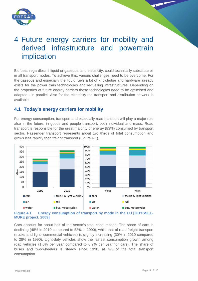
For energy consumption, transport and especially road transport will play a major role also in the future, in goods and people transport, both individual and mass. Road transport is responsible for the great majority of energy (83%) consumed by transport sector. Passenger transport represents about two thirds of total consumption and grows less rapidly than freight transport (Figure 4.1).
Figure 4.1 Energy consumption of transport by mode in the EU [ODYSSEE-MURE project, 2009]
Cars account for about half of the sector’s total consumption. The share of cars is declining (48% in 2010 compared to 53% in 1990), while that of road freight transport (trucks and light- commercial vehicles) is slightly increasing (30% in 2010 compared to 28% in 1990). Light-duty vehicles show the fastest consumption growth among road vehicles (1.6% per year compared to 0.9% per year for cars). The share of buses and two-wheelers is steady since 1990, at 4% of the total transport consumption.
www.ertrac.org
Page 15 of 110
In the latest report of ‘Transport and Environment Reporting Mechanism’ (TERM), the ‘European Environmental Agency’ (EEA) reports that freight transport demand increased sharply in 2010, exceeding GDP growth. Rail freight marginally increased its share from its lowest level in 2009 to just 17% in EU-27. Passenger transport demand fell slightly in 2010 despite the return to GDP growth. Modal split for passenger transport remains stable for EU-15 Member States with car modal share at well over 80%. In the EU-12, car modal share has reached EU-15 levels in some Member States, however, bus modal share increased marginally from its lowest level in 2009.
Passenger transport demand expressed in car, bus and rail passenger-kilometres (pkm) in the EEA-32 member countries increased by 10% between 2000 and 2010, at an annual rate of just less than 1%. Cars represent the largest share of inland passenger transport in the EEA-32 member countries. Bus travel had the second largest modal share in all but seven European countries, where rail accounted for a higher percentage of pkm (Austria, France, Germany, the Netherlands, Sweden, Switzerland and the United Kingdom).
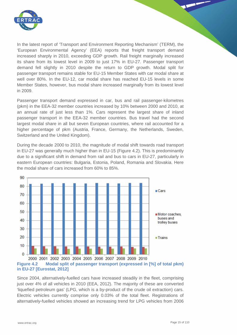
During the decade 2000 to 2010, the magnitude of modal shift towards road transport in EU-27 was generally much higher than in EU-15 (Figure 4.2). This is predominantly due to a significant shift in demand from rail and bus to cars in EU-27, particularly in eastern European countries: Bulgaria, Estonia, Poland, Romania and Slovakia. Here the modal share of cars increased from 60% to 85%.
Figure 4.2 Modal split of passenger transport (expressed in [%] of total pkm) in EU-27 [Eurostat, 2012]
Since 2004, alternatively-fuelled cars have increased steadily in the fleet, comprising just over 4% of all vehicles in 2010 (EEA, 2012). The majority of these are converted ‘liquefied petroleum gas’ (LPG, which is a by-product of the crude oil extraction) cars. Electric vehicles currently comprise only 0.03% of the total fleet. Registrations of alternatively-fuelled vehicles showed an increasing trend for LPG vehicles from 2006
www.ertrac.org
Page 16 of 110
onwards. However, LPG registrations declined rapidly from 2009, mainly caused by the significant market slump in France and Italy, a development that was precipitated by the change in economic incentive schemes and the trend is likely to stay negative mainly due to the lack of European OEM support. There are no specific targets for the percentage of the vehicle fleet that use alternative fuels, but the European Commission aims for European substitution of fossil oil and much greater share of alternative and renewable fuels.
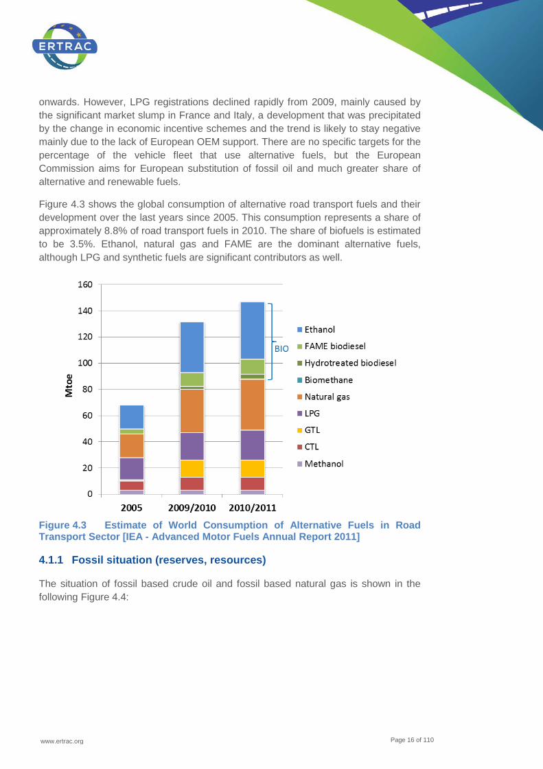
Figure 4.3 shows the global consumption of alternative road transport fuels and their development over the last years since 2005. This consumption represents a share of approximately 8.8% of road transport fuels in 2010. The share of biofuels is estimated to be 3.5%. Ethanol, natural gas and FAME are the dominant alternative fuels, although LPG and synthetic fuels are significant contributors as well.
Figure 4.3 Estimate of World Consumption of Alternative Fuels in Road Transport Sector [IEA - Advanced Motor Fuels Annual Report 2011]
4.1.1 Fossil situation (reserves, resources)
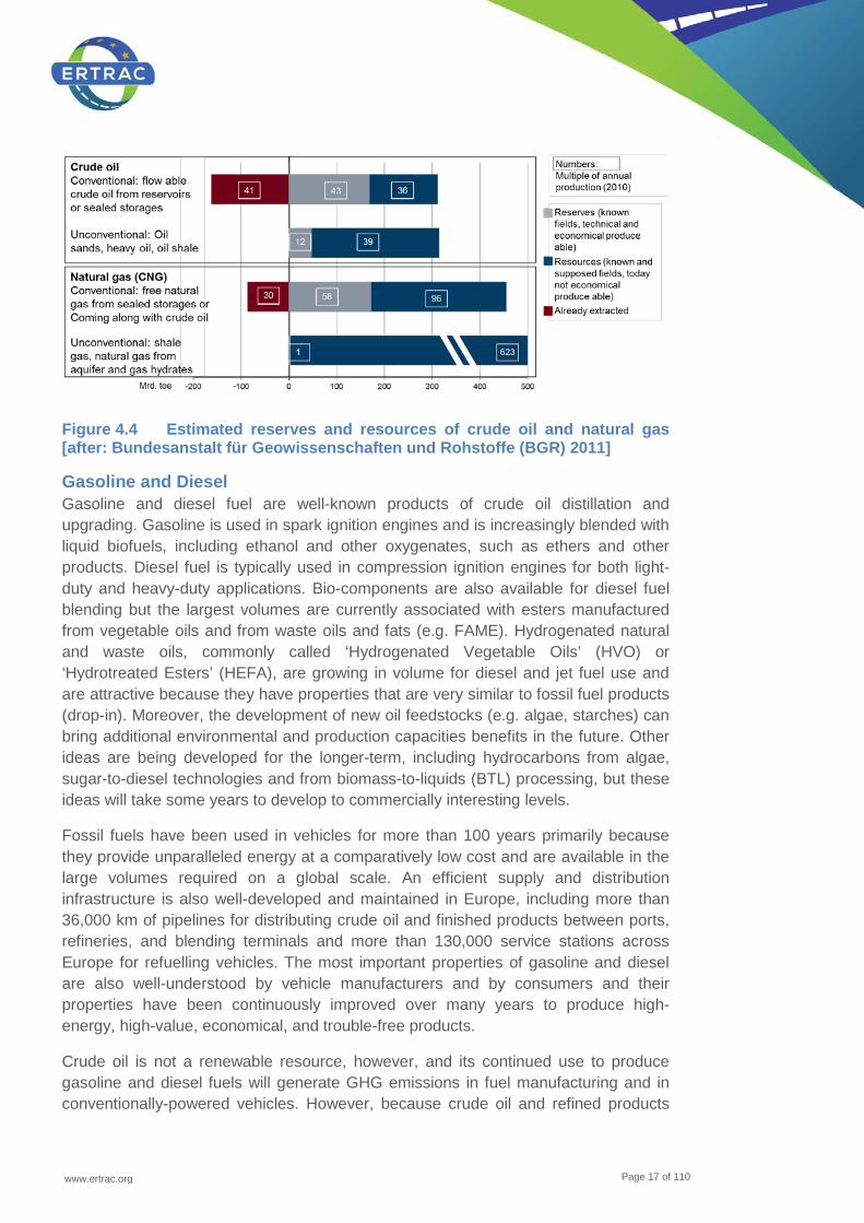
The situation of fossil based crude oil and fossil based natural gas is shown in the following Figure 4.4:
www.ertrac.org
Page 17 of 110
Figure 4.4 Estimated reserves and resources of crude oil and natural gas [after: Bundesanstalt für Geowissenschaften und Rohstoffe (BGR) 2011]
Gasoline and Diesel Gasoline and diesel fuel are well-known products of crude oil distillation and upgrading. Gasoline is used in spark ignition engines and is increasingly blended with liquid biofuels, including ethanol and other oxygenates, such as ethers and other products. Diesel fuel is typically used in compression ignition engines for both light-duty and heavy-duty applications. Bio-components are also available for diesel fuel blending but the largest volumes are currently associated with esters manufactured from vegetable oils and from waste oils and fats (e.g. FAME). Hydrogenated natural and waste oils, commonly called ‘Hydrogenated Vegetable Oils’ (HVO) or ‘Hydrotreated Esters’ (HEFA), are growing in volume for diesel and jet fuel use and are attractive because they have properties that are very similar to fossil fuel products (drop-in). Moreover, the development of new oil feedstocks (e.g. algae, starches) can bring additional environmental and production capacities benefits in the future. Other ideas are being developed for the longer-term, including hydrocarbons from algae, sugar-to-diesel technologies and from biomass-to-liquids (BTL) processing, but these ideas will take some years to develop to commercially interesting levels.
Fossil fuels have been used in vehicles for more than 100 years primarily because they provide unparalleled energy at a comparatively low cost and are available in the large volumes required on a global scale. An efficient supply and distribution infrastructure is also well-developed and maintained in Europe, including more than 36,000 km of pipelines for distributing crude oil and finished products between ports, refineries, and blending terminals and more than 130,000 service stations across Europe for refuelling vehicles. The most important properties of gasoline and diesel are also well-understood by vehicle manufacturers and by consumers and their properties have been continuously improved over many years to produce high-energy, high-value, economical, and trouble-free products.
Crude oil is not a renewable resource, however, and its continued use to produce gasoline and diesel fuels will generate GHG emissions in fuel manufacturing and in conventionally-powered vehicles. However, because crude oil and refined products
www.ertrac.org
Page 18 of 110
are typically transported and upgraded in large volumes and in large manufacturing units, WtT GHG emissions typically represent only about 17% of total WtW GHG emissions from conventional vehicles. The remaining 83% of GHG emissions result from the combustion of fuel to produce useful work, some of which is subsequently lost to friction and waste heat.
It is also well-documented that Europe has limited sources of crude oil production within its borders so fossil fuel use increases Europe’s dependence on imported energy. Over the past 15 - 20 years, Europe’s demand for diesel fuel has increased because of consumer preference for diesel passenger cars and business preference of diesel commercial vehicles (e.g. heavy-duty trucks). This increasing diesel demand is more than can be produced in today’s European refineries, resulting in greater imports of distillate fuels from trading partners. At the same time, excess gasoline production from European refineries must be exported to other parts of the world. Increasing the use of bio-blending components into gasoline will increase this imbalance between diesel and gasoline demand, making Europe more dependent on exports of gasoline and on imports of distillate products. This imbalance in the diesel / gasoline ratio is a serious concern that is not expected to be corrected for many years. Increased demand for middle distillates can also be expected in aviation and in the marine sector, the latter due to tightening environmental regulations.
Compressed Natural Gas (CNG) and Liquefied Natural Gas (LNG) When referring to alternative fuels of fossil origin, it is important to take into account that some fossil fuels are perfect enablers for the integration of renewables and the engine technology and combustion behaviour will not change. This is specifically the case for Natural Gas, which has the same molecular structure as renewably sourced methane, including biomethane from waste and other advanced feedstock or synthetic methane from Power to Gas technologies, and no blending limitations of fossil and renewably sourced methane would occur. CNG and LNG technologies therefore refer to methane from both fossil and renewable sources. These aspects will be more detailed explained in chapter 4.5 on CNG and LNG.
Natural Gas is a mixture of hydrocarbons - mainly consisting of methane (CH4) (values typically ranging from 87 - 97%). It can also contain some minor impurities such as nitrogen or carbon dioxide. It is naturally produced by the decomposition of organic matter over extensive periods of time (generally millions of years).
Natural Gas is a fundamental strategic option to fulfil the EU target to move towards a decarbonisation and oil replacement scenario for the transportation sector as technical, economic and social acceptability and sustainability criteria are fully fulfilled. It represents a viable immediate solution with huge potential in the short, medium and long term option for energy diversification and to minimise the transportation system dependence on crude oil due to globally wider reserves and a better geopolitical distribution. In addition to that, unconventional shale gas reserves have increased with estimated reserves up to 150 years for Europe and theoretically even more than some hundred years. The trading of LNG as a global commodity
www.ertrac.org
Page 19 of 110
should lead to an increasingly and stronger decoupling of gas and oil prices and consequently also leading to a favourable fuel price development of CNG and LNG vs. oil derived fuels. The available vast feedstock material for production of methane from renewable sources adds on to this huge security of supply of natural gas or liquid fuels and opens the way for locally sourced production of methane as a fuel in Europe.
For increasing energy density, when used for transportation purposes, natural gas can either be found in compressed or liquefied form:
• Compressed Natural Gas (CNG) refers to Natural Gas, which has been compressed after processing, for storage and/ or transportation purposes. CNG is mainly used for vehicles, and typically compressed (as maximum working pressure) to 200 bar in gaseous state.
• Liquefied Natural Gas (LNG) refers to Natural Gas, which has been liquefied after processing, for storage and/ or transportation purposes. LNG temperature is about minus 161.7°C at atmospheric pressure but, when used as an automotive fuel, it can be stored inside on-board cryogenic tanks (vacuum-isolated stainless-steel vessels) also at different operating pressures and temperature ranges.
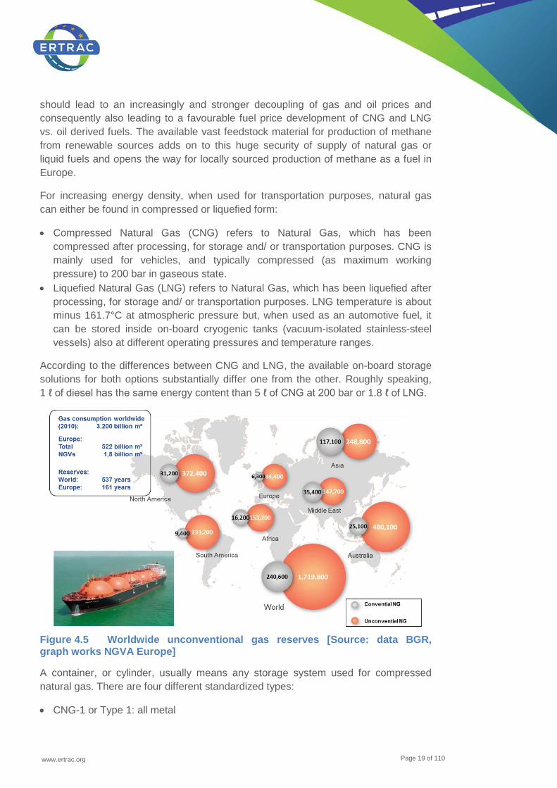
According to the differences between CNG and LNG, the available on-board storage solutions for both options substantially differ one from the other. Roughly speaking, 1 ℓ of diesel has the same energy content than 5 ℓ of CNG at 200 bar or 1.8 ℓ of LNG.
Figure 4.5 Worldwide unconventional gas reserves [Source: data BGR, graph works NGVA Europe]
A container, or cylinder, usually means any storage system used for compressed natural gas. There are four different standardized types:
• CNG-1 or Type 1: all metal

www.ertrac.org
Page 20 of 110
• CNG-2 or Type 2: metal liner reinforced with resin impregnated continuous filament (hoop wrapped)
• CNG-3 or Type 3: metal liner reinforced with resin impregnated continuous filament (fully wrapped)
• CNG-4 or Type 4: resin impregnated continuous filament with a non-metallic liner (all composite)
Figure 4.6 Growing spread between oil and gas prices7 [LNG spot market]
In Europe the CNG pressure level is limited to 200 bar. Advanced storage efficiency could be realized by the increase of the operating pressure up to 260 bar (as with US standards) or 350 bar (as with today’s pressure standard for hydrogen fuelled city buses).
A tank, or vessel, usually means any storage system used for liquefied natural gas. When used as a transportation fuel, the LNG cryogenic tank (vacuum isolated stainless-steel vessel) can have different operating pressure ranges.
These reasons above regarding NG chemical and physical properties lead to the fact that NG, when burnt into an internal combustion engine is an intrinsically clean fuel with the lowest carbon content and lowest CO2 tailpipe emissions among all the hydrocarbon fuels, able to help to significantly reduce greenhouse gas. With regards to the expected growing trend towards increased transportation of passengers and goods and demand for individual mobility in the EU, the immediate availability of an affordable and environmental friendly fuel, such as Natural Gas is becoming fundamentally important.
The Natural Gas Vehicle technology is proven and available; incremental technology cost is competitive with regards to other alternative propulsion and based on mature and robust technology ready to meet a significant growing market demand. Also from
7 1 $ / MMBTU = 2.81 € / MWh
www.ertrac.org
Page 21 of 110
the point of view of the end user, CNG results an attractive fuel due to its lower operating cost compared to conventional and other alternative fuels such as LPG.
Natural Gas supports progressive diversification in the fossil fuels mix and in combination with biomethane and synthetic natural gas, the overall carbon footprint for CNG and LNG vehicles will be further improved. Further R&D to further improve CNG and LNG drivetrain technologies (e.g. high pressure direct injection in spark ignited and compression injection engines) will be necessary to further exploit the full potential of Natural Gas Vehicles.
Liquefied petroleum gas (LPG) Liquefied petroleum gas, sometimes called ‘autogas’, is a mixture of propane and butane. LPG is a by-product of the crude oil refining and natural gas clean-up. Due to the dependence on the availability to crude oil LPG is not an alternative energy carrier. Alternative pathways to produce decarbonised LPG are not in the focus of research.
New alternatives from fossil sources Natural gas or coal could be also converted to other gaseous or liquid forms. Examples of this technology are ‘gas to liquid’ (GtL) or ‘coal to liquid’ (CtL). In both technologies the hydro carbon carrier is gasified (to hydrogen and carbon monoxide as synthesis gas) and later recombined to liquid fuel by e.g. Fischer-Tropsch synthesis. The same process is also use for the pathway ‘Biomass to liquid’ (BtL), see 4.4.2. Synthetic hydrocarbons (XtL), whether from coal, gas or biomass can be drop-in fuel, eliminating the need for dedicated refuelling infrastructure and dedicated vehicles.
4.1.2 ‘First generation’ / ‘State of the art’ biofuels
‘First generation’ biofuels started their market introduction with the 1st oil crisis in the early seventies. Based on agricultural commodities such as cereals, sugar beet and sugar cane as well as vegetable oils and using conversion technologies well established in food or chemical industries, their production did not pose major technical problems. However economic viability of these processes originally aimed at higher value markets needed to be optimised and scaled up to the larger quantities required in the fuel market. Consumption in EU27 in 2012 amounted to 14.4 Mtoe, dominated by 79% biodiesel with 20% bioethanol on 2nd place.
From the end-use point of view, the use of first generation biofuels such as ethanol (EtOH) and conventional esterified biodiesel (FAME) is often limited for technical reasons (so-called blending wall issues, i.e. incompatibility issues).
Some definitions are needed:
• First generation, second generation, advanced • Sustainability depends on feedstock • Sustainability does not guarantee end-use performance
www.ertrac.org
Page 22 of 110
• Blending wall • Drop-in etc. etc.
Ethanol The most popular biogenous component in gasoline engines is Ethanol (EtOH). Some countries in the EU have already introduced up to 10 vol.% of Ethanol in gasoline fuel grades.
EtOH is a naturally widespread chemical, produced by ripe fruits and by wild yeasts or bacteria through fermentation. Ethanol from biomass can be produced from any feedstock containing appreciable amounts of sugar or materials that can be converted into sugar.
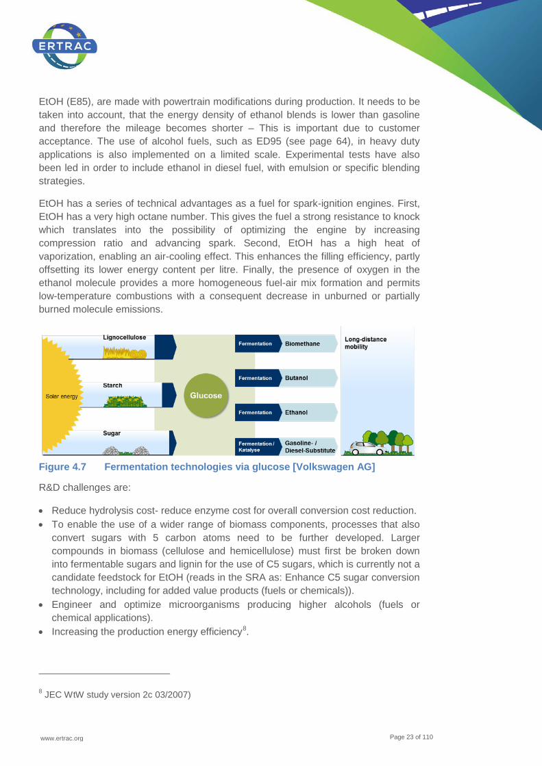
Fermentation (biotechnology) is the predominant pathway for EtOH production. Biomass can also be converted to EtOH via biotechnological and thermochemical pathways (see Figure 4.7; Pathway from sugar or starch to Ethanol).
In the biochemical pathways, the most common raw materials are sugar cane and corn, and in temperate climates also sugar beet, wheat or potatoes. The overall fermentation process starting from glucose is:
C6H12O6 2 C2H5OH + 2 CO2 Adapted yeasts, for example Saccharomyces cerevisiae are used and fermentation can be carried out with or without the presence of oxygen. With oxygen some yeast are prone to respiration, the conversion of sugars to carbon dioxide and water. As EtOH is a toxin, there is a limit to the maximum concentration in the brew produced by the yeasts. This results in a high energy demand for EtOH purification by distillation.
In industrial processes an efficiency of about 90 to 95% of theoretical yields can be reached. But, unmodified yeast will only convert sugars with six carbon atoms. As sugars with six carbon atoms are only a part of the biomass the overall conversion efficiency is much lower.
Non-biotechnological methods for production of EtOH have been developed. EtOH from chemical conversion routes is called synthetic ethanol. The most common chemical process for EtOH production is the acid-catalysed hydration of ethylene:
C2H4 + H2O C2H5OH Ethylene is obtained from petrochemical feedstocks. Phosphoric acid is mostly used as a catalyst.
EtOH can also be produced from synthesis gas through chemical synthesis. In addition, certain microorganisms are able to digest synthesis gas to produce ethanol.
Low-percentage ethanol-gasoline blends (E5, E10) can be effectively used in most conventional spark-ignition engines with no major technical changes, while modern ‘flex-fuel vehicles’ (FFV), which can run on any gasoline-EtOH mixture up to 85%
www.ertrac.org
Page 23 of 110
EtOH (E85), are made with powertrain modifications during production. It needs to be taken into account, that the energy density of ethanol blends is lower than gasoline and therefore the mileage becomes shorter – This is important due to customer acceptance. The use of alcohol fuels, such as ED95 (see page 64), in heavy duty applications is also implemented on a limited scale. Experimental tests have also been led in order to include ethanol in diesel fuel, with emulsion or specific blending strategies.
EtOH has a series of technical advantages as a fuel for spark-ignition engines. First, EtOH has a very high octane number. This gives the fuel a strong resistance to knock which translates into the possibility of optimizing the engine by increasing compression ratio and advancing spark. Second, EtOH has a high heat of vaporization, enabling an air-cooling effect. This enhances the filling efficiency, partly offsetting its lower energy content per litre. Finally, the presence of oxygen in the ethanol molecule provides a more homogeneous fuel-air mix formation and permits low-temperature combustions with a consequent decrease in unburned or partially burned molecule emissions.
Figure 4.7 Fermentation technologies via glucose [Volkswagen AG]
R&D challenges are:
• Reduce hydrolysis cost- reduce enzyme cost for overall conversion cost reduction. • To enable the use of a wider range of biomass components, processes that also
convert sugars with 5 carbon atoms need to be further developed. Larger compounds in biomass (cellulose and hemicellulose) must first be broken down into fermentable sugars and lignin for the use of C5 sugars, which is currently not a candidate feedstock for EtOH (reads in the SRA as: Enhance C5 sugar conversion technology, including for added value products (fuels or chemicals)).
• Engineer and optimize microorganisms producing higher alcohols (fuels or chemical applications).
• Increasing the production energy efficiency8.
8 JEC WtW study version 2c 03/2007)
www.ertrac.org
Page 24 of 110
Fatty acid methyl ester (FAME / biodiesel) FAME is produced from vegetable oils, animal fats or waste cooking oils by trans-esterification and esterification. In the trans-esterification process a triglyceride reacts with an alcohol in the presence of a catalyst (liquid or solid), forming a mixture of fatty acids esters and an alcohol, whereas the esterification process is necessary to convert free fatty acids of oils or fats to fatty acid esters and water. Using triglycerides result in the production of by-product glycerol.
Trans-esterification is a reversible reaction and is carried out by mixing the reactants. A strong base or a strong acid can be used as a catalyst. At the industrial scale, sodium or potassium methanolate is mostly used. Some recent industrial developments have also been made in order to use a solid catalyst instead of liquid one, enabling to strongly increase the quality of glycerol by-product. This higher quality allows an enhanced valorisation of the products and consequently a substantial increase in the economic and environmental balance of the process9.
The production of biodiesel is relatively simple from a technical standpoint, but is still often challenging, when dealing multiple feedstocks like ‘used cooking oil’ (UCO) or trap grease. This is also allowing the construction of small decentralized production units without excessive extra costs. This limits the need to transport raw materials long distances and permits operations to start with modest-sized installations.
The end products of the trans-esterification process are raw biodiesel and raw glycerol. After a cleaning step biodiesel is produced. Based on used raw material the purified glycerol can be used in the food and cosmetic industries, as well as in the oleo-chemical industry. The glycerol can also be used as a substrate for anaerobic digestion.
‘Fatty Acid Methyl Esters’ (FAME) are esters of fatty acids. The physical characteristics of fatty acid esters are closer to those of fossil diesel fuels than pure vegetable oils, but properties depend on the type of vegetable oil. A mixture of different fatty acid methyl esters is commonly referred to as biodiesel, which is a renewable alternative fuel. It is also non-toxic and biodegradable.
Some properties of biodiesel are different from those of fossil diesel and for correct low temperature behaviour and for slowing down oxidation processes biodiesel requires a different set of additives than fossil diesel. Impurities, such as metals, in FAME must be limited for use as a motor fuel.
The R&D challenges are:
• Strengthen the sustainability of FAME with regard to both economic and environmental performance. Environmental issues to be taken into consideration include GHG emissions, energy balances, water balance and management as well as material input
9 http://www.axens.net/product/technology-licensing/10104/esterfip-h.html
www.ertrac.org
Page 25 of 110
• Broadening of feedstock base • Increasing the production energy • Commercialization of a trans-esterification process based on heterogeneous
catalysis (process intensification, higher glycerol purity, etc.) • Ensure high level of quality in respect with FQD standard
4.1.3 State of the art infrastructure
Conventional Fuels In Europe today, more than 130,000 service stations are available to consumers, often at almost every other street corner in populated areas. On an average day, more than 25 million vehicles are refuelled with approximately one billion litres of liquid fuels. These service stations are refuelled from a sophisticated and highly-developed supply and distribution network that consists of refineries, blending terminals, and service stations, efficiently interconnected by pipelines, barge operations, and delivery trucks. Approximately 36,000 km of pipelines ensures the efficient movement of crude oil and refined products across Europe. Blending terminals are typically used to blend in certain bio-components, especially ethanol, before the finished product is delivered to the service station. Typically, proprietary additive packages are also added at the terminal location in order to ensure the performance of fuels in consumers’ vehicles.
Importantly, fuel taxes collected by European service stations represent about 7% on average of total Member State tax revenues.
Compressed Natural Gas (CNG), Liquefied Natural Gas (LNG) and methane stations today
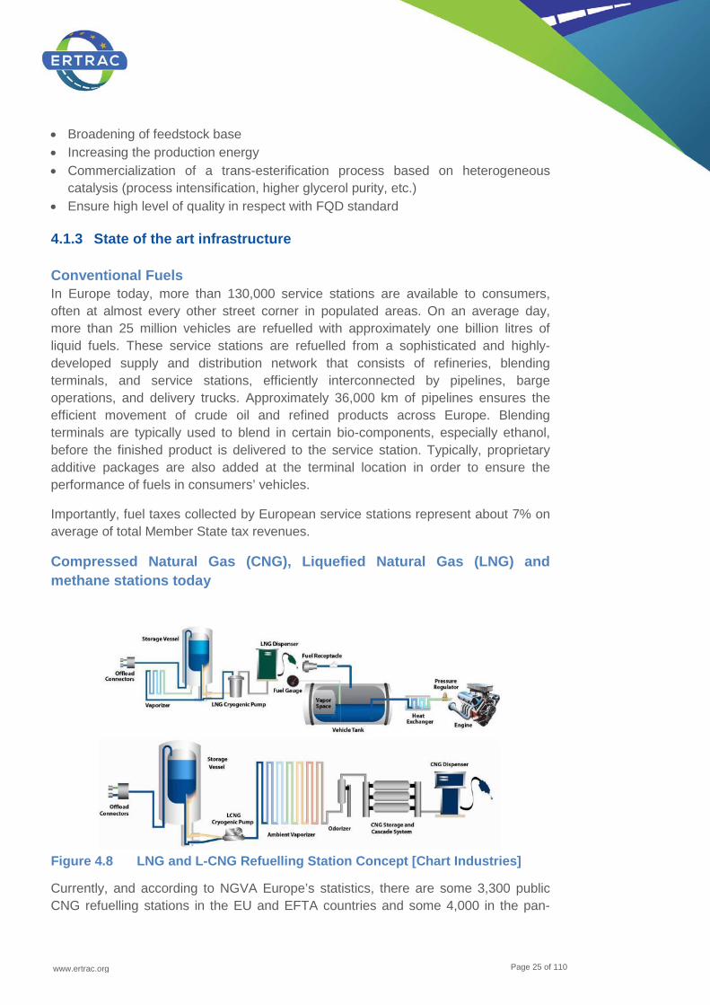
Figure 4.8 LNG and L-CNG Refuelling Station Concept [Chart Industries]
Currently, and according to NGVA Europe’s statistics, there are some 3,300 public CNG refuelling stations in the EU and EFTA countries and some 4,000 in the pan-
www.ertrac.org
Page 26 of 110
European territory, while there are to date only some 50 LNG and L-CNG filling stations existing. Normally CNG refuelling stations are connected to the NG gas grid as the feeding source where NG is compressed up to 200 bar for automotive use as CNG. During the process the gas is also dried and filtered particularly in absence of a gas grid (e.g. Eastern part of Sweden). Movable CNG racks are used as feeding buffers to stations where no grid connections was possible.
Some 3 - 4 years ago new developments started to use LNG either directly as a fuel or for CNG supply when no grid connections were available. This describes the so called L-CNG refuelling station concept in which, LNG is stored in a stationary tank and the cryogenic gas is then gasified the in a heat exchanger, odorised and compressed to obtain CNG as a final product (total energy used for compression much lower than grid gas, due to the pressure built during gasification).
Additionally, when L-CNG stations started to appear in Europe, the industry started looking at the possibility of enabling the direct use of LNG as a vehicle fuel and especially for Heavy-Duty applications. The Figure 4.10 provides a schematic on the LNG and L-CNG refuelling station concept.
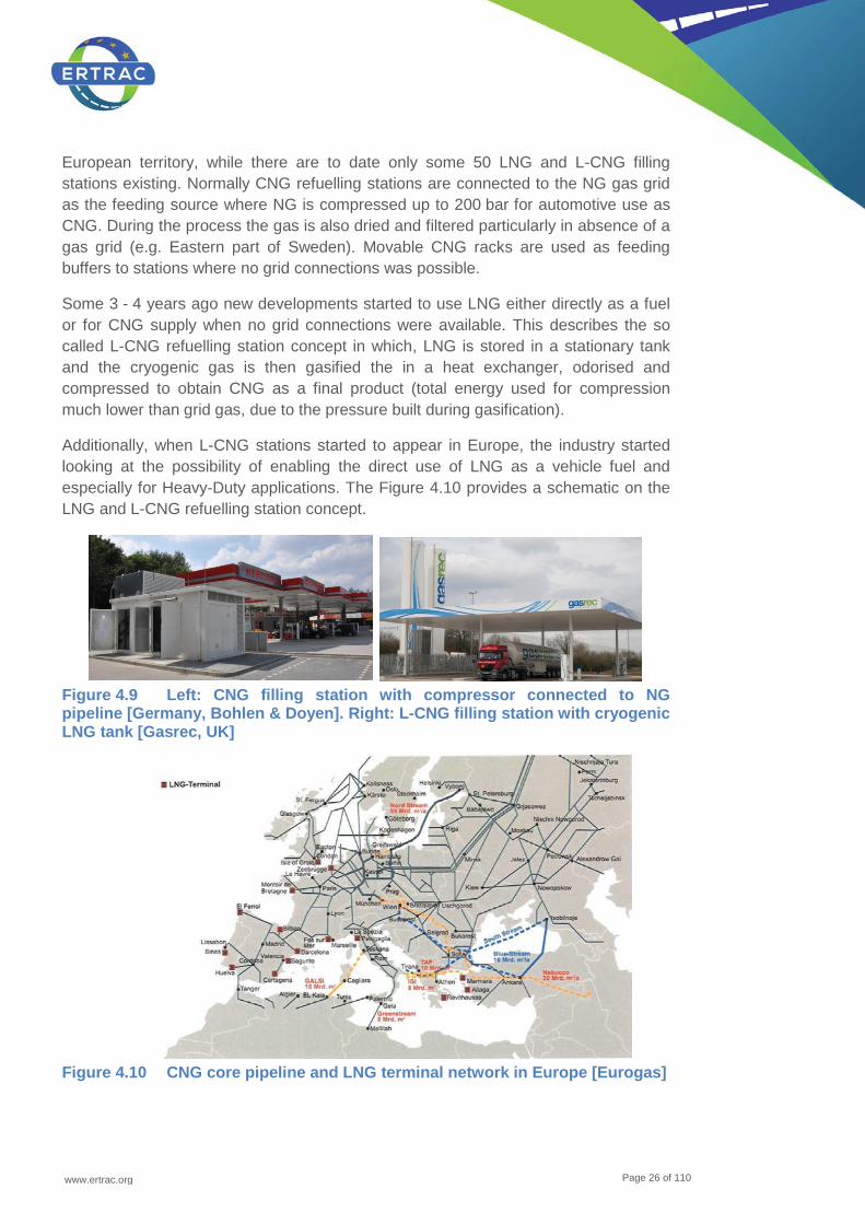
Figure 4.9 Left: CNG filling station with compressor connected to NG pipeline [Germany, Bohlen & Doyen]. Right: L-CNG filling station with cryogenic LNG tank [Gasrec, UK]
Figure 4.10 CNG core pipeline and LNG terminal network in Europe [Eurogas]
www.ertrac.org
Page 27 of 110
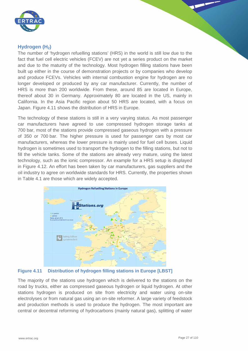
Hydrogen (H2) The number of ‘hydrogen refuelling stations’ (HRS) in the world is still low due to the fact that fuel cell electric vehicles (FCEV) are not yet a series product on the market and due to the maturity of the technology. Most hydrogen filling stations have been built up either in the course of demonstration projects or by companies who develop and produce FCEVs. Vehicles with internal combustion engine for hydrogen are no longer developed or produced by any car manufacturer. Currently, the number of HRS is more than 200 worldwide. From these, around 85 are located in Europe, thereof about 30 in Germany. Approximately 80 are located in the US, mainly in California. In the Asia Pacific region about 50 HRS are located, with a focus on Japan. Figure 4.11 shows the distribution of HRS in Europe.
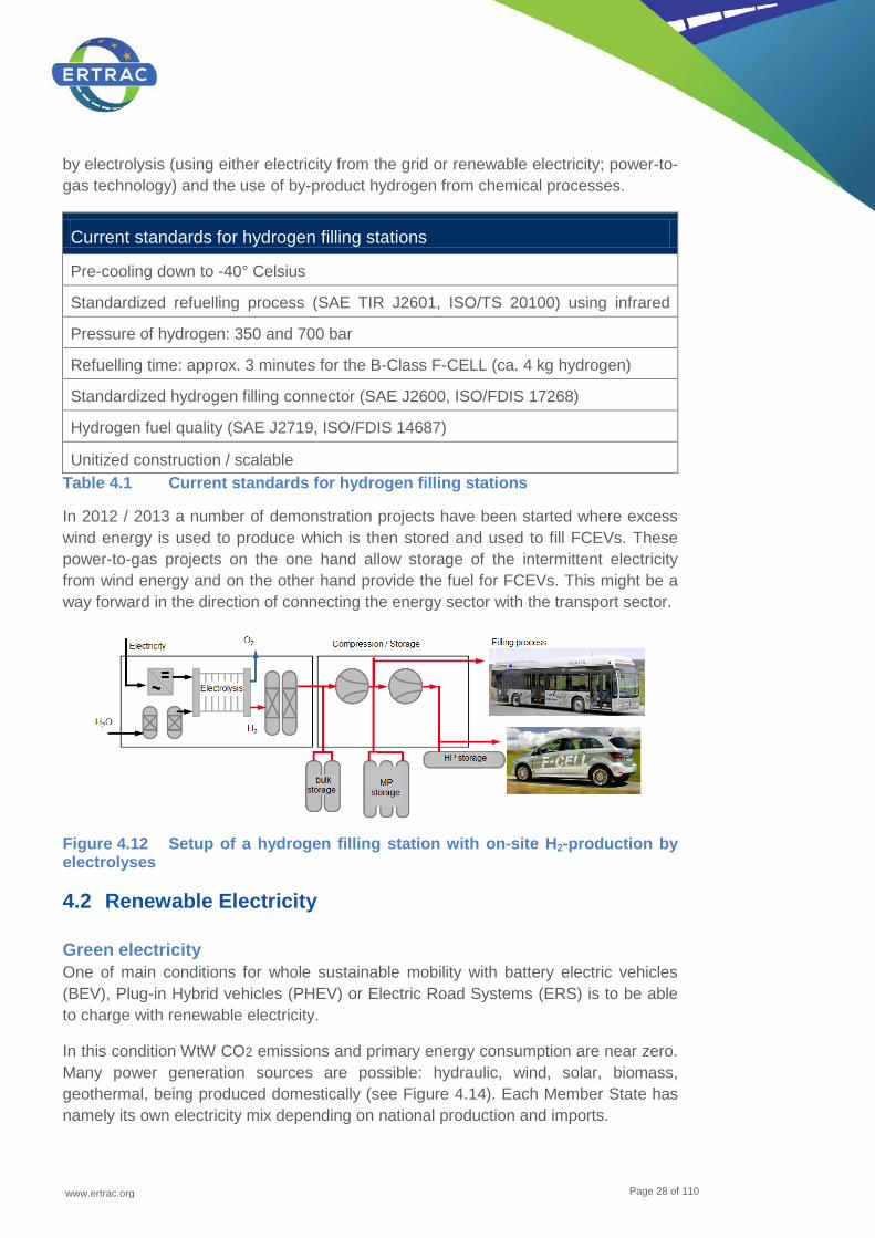
The technology of these stations is still in a very varying status. As most passenger car manufacturers have agreed to use compressed hydrogen storage tanks at 700 bar, most of the stations provide compressed gaseous hydrogen with a pressure of 350 or 700 bar. The higher pressure is used for passenger cars by most car manufacturers, whereas the lower pressure is mainly used for fuel cell buses. Liquid hydrogen is sometimes used to transport the hydrogen to the filling stations, but not to fill the vehicle tanks. Some of the stations are already very mature, using the latest technology, such as the ionic compressor. An example for a HRS setup is displayed in Figure 4.12. An effort has been taken by car manufacturers, gas suppliers and the oil industry to agree on worldwide standards for HRS. Currently, the properties shown in Table 4.1 are those which are widely accepted.
Figure 4.11 Distribution of hydrogen filling stations in Europe [LBST]
The majority of the stations use hydrogen which is delivered to the stations on the road by trucks, either as compressed gaseous hydrogen or liquid hydrogen. At other stations hydrogen is produced on site from electricity and water using on-site electrolyses or from natural gas using an on-site reformer. A large variety of feedstock and production methods is used to produce the hydrogen. The most important are central or decentral reforming of hydrocarbons (mainly natural gas), splitting of water
www.ertrac.org
Page 28 of 110
by electrolysis (using either electricity from the grid or renewable electricity; power-to-gas technology) and the use of by-product hydrogen from chemical processes.
Current standards for hydrogen filling stations
Pre-cooling down to -40° Celsius
Standardized refuelling process (SAE TIR J2601, ISO/TS 20100) using infrared
Pressure of hydrogen: 350 and 700 bar
Refuelling time: approx. 3 minutes for the B-Class F-CELL (ca. 4 kg hydrogen)
Standardized hydrogen filling connector (SAE J2600, ISO/FDIS 17268)
Hydrogen fuel quality (SAE J2719, ISO/FDIS 14687)
Unitized construction / scalable Table 4.1 Current standards for hydrogen filling stations
In 2012 / 2013 a number of demonstration projects have been started where excess wind energy is used to produce which is then stored and used to fill FCEVs. These power-to-gas projects on the one hand allow storage of the intermittent electricity from wind energy and on the other hand provide the fuel for FCEVs. This might be a way forward in the direction of connecting the energy sector with the transport sector.
Figure 4.12 Setup of a hydrogen filling station with on-site H2-production by electrolyses
4.2 Renewable Electricity
Green electricity One of main conditions for whole sustainable mobility with battery electric vehicles (BEV), Plug-in Hybrid vehicles (PHEV) or Electric Road Systems (ERS) is to be able to charge with renewable electricity.
In this condition WtW CO2 emissions and primary energy consumption are near zero. Many power generation sources are possible: hydraulic, wind, solar, biomass, geothermal, being produced domestically (see Figure 4.14). Each Member State has namely its own electricity mix depending on national production and imports.
www.ertrac.org
Page 29 of 110
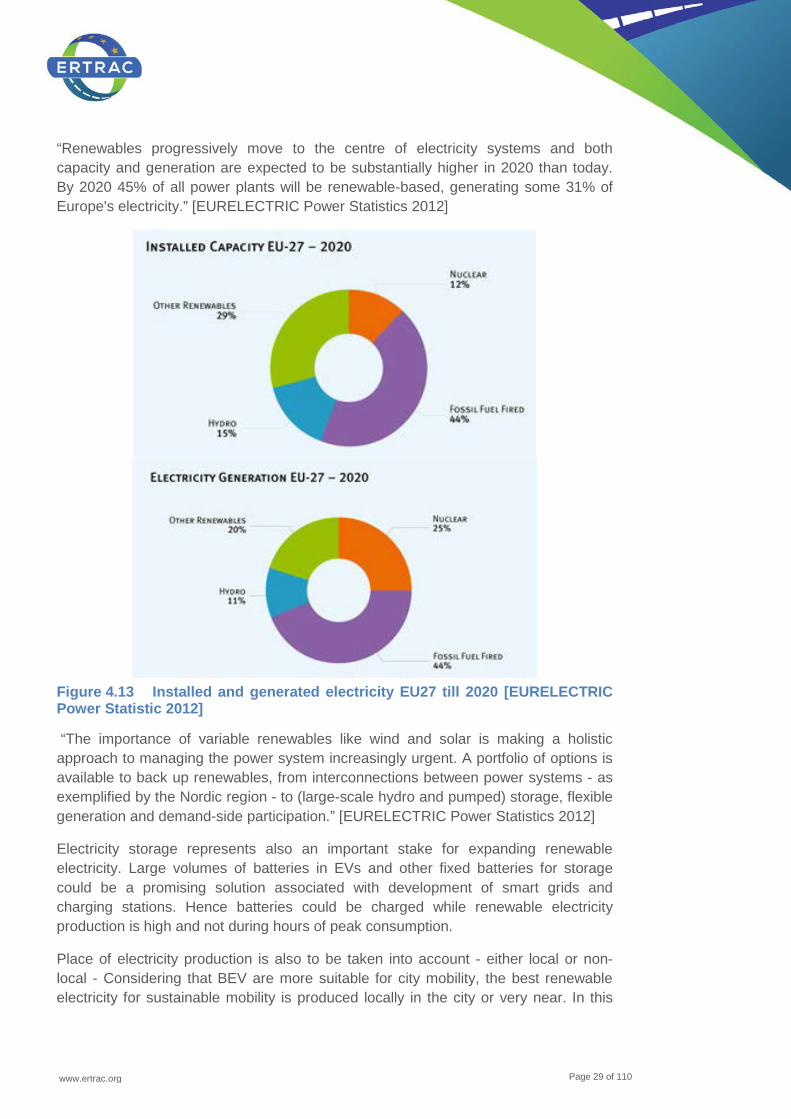
“Renewables progressively move to the centre of electricity systems and both capacity and generation are expected to be substantially higher in 2020 than today. By 2020 45% of all power plants will be renewable-based, generating some 31% of Europe's electricity.” [EURELECTRIC Power Statistics 2012]
Figure 4.13 Installed and generated electricity EU27 till 2020 [EURELECTRIC Power Statistic 2012]
“The importance of variable renewables like wind and solar is making a holistic approach to managing the power system increasingly urgent. A portfolio of options is available to back up renewables, from interconnections between power systems - as exemplified by the Nordic region - to (large-scale hydro and pumped) storage, flexible generation and demand-side participation.” [EURELECTRIC Power Statistics 2012]
Electricity storage represents also an important stake for expanding renewable electricity. Large volumes of batteries in EVs and other fixed batteries for storage could be a promising solution associated with development of smart grids and charging stations. Hence batteries could be charged while renewable electricity production is high and not during hours of peak consumption.
Place of electricity production is also to be taken into account - either local or non-local - Considering that BEV are more suitable for city mobility, the best renewable electricity for sustainable mobility is produced locally in the city or very near. In this
www.ertrac.org
Page 30 of 110
purpose, one of the best solutions is to develop positive energy buildings, associated with smart grid, energy smart management and electricity storage. For example in France by 2020 all new buildings should be energy positive, i.e. produce energy. Of course charging infrastructure has to be developed simultaneously with the buildings with a sufficient number of charging stations.
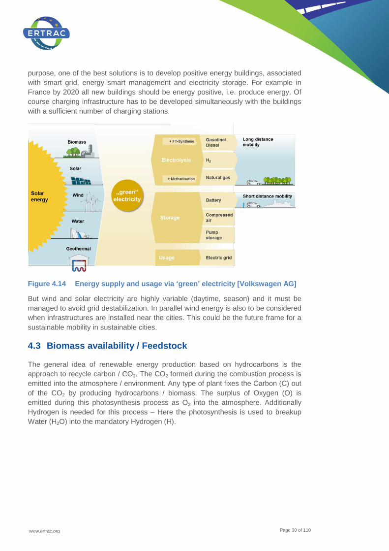
Figure 4.14 Energy supply and usage via ‘green’ electricity [Volkswagen AG]
But wind and solar electricity are highly variable (daytime, season) and it must be managed to avoid grid destabilization. In parallel wind energy is also to be considered when infrastructures are installed near the cities. This could be the future frame for a sustainable mobility in sustainable cities.
4.3 Biomass availability / Feedstock
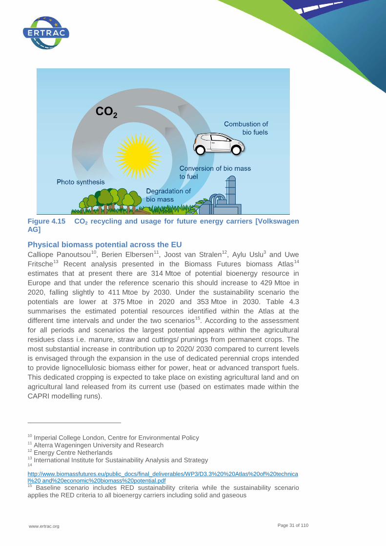
The general idea of renewable energy production based on hydrocarbons is the approach to recycle carbon / CO2. The CO2 formed during the combustion process is emitted into the atmosphere / environment. Any type of plant fixes the Carbon (C) out of the CO2 by producing hydrocarbons / biomass. The surplus of Oxygen (O) is emitted during this photosynthesis process as O2 into the atmosphere. Additionally Hydrogen is needed for this process – Here the photosynthesis is used to breakup Water (H2O) into the mandatory Hydrogen (H).
www.ertrac.org
Page 31 of 110
Figure 4.15 CO2 recycling and usage for future energy carriers [Volkswagen AG]
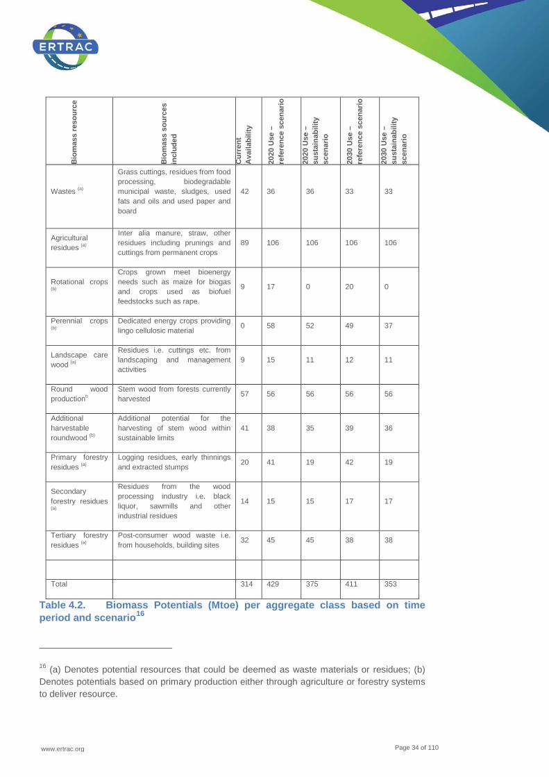
Physical biomass potential across the EU Calliope Panoutsou10, Berien Elbersen11, Joost van Stralen12, Aylu Uslu3 and Uwe Fritsche13 Recent analysis presented in the Biomass Futures biomass Atlas14 estimates that at present there are 314 Mtoe of potential bioenergy resource in Europe and that under the reference scenario this should increase to 429 Mtoe in 2020, falling slightly to 411 Mtoe by 2030. Under the sustainability scenario the potentials are lower at 375 Mtoe in 2020 and 353 Mtoe in 2030. Table 4.3 summarises the estimated potential resources identified within the Atlas at the different time intervals and under the two scenarios15. According to the assessment for all periods and scenarios the largest potential appears within the agricultural residues class i.e. manure, straw and cuttings/ prunings from permanent crops. The most substantial increase in contribution up to 2020/ 2030 compared to current levels is envisaged through the expansion in the use of dedicated perennial crops intended to provide lignocellulosic biomass either for power, heat or advanced transport fuels. This dedicated cropping is expected to take place on existing agricultural land and on agricultural land released from its current use (based on estimates made within the CAPRI modelling runs).
10 Imperial College London, Centre for Environmental Policy 11 Alterra Wageningen University and Research 12 Energy Centre Netherlands 13 International Institute for Sustainability Analysis and Strategy 14 http://www.biomassfutures.eu/public_docs/final_deliverables/WP3/D3.3%20%20Atlas%20of%20technical%20 and%20economic%20biomass%20potential.pdf 15 Baseline scenario includes RED sustainability criteria while the sustainability scenario applies the RED criteria to all bioenergy carriers including solid and gaseous
www.ertrac.org
Page 32 of 110
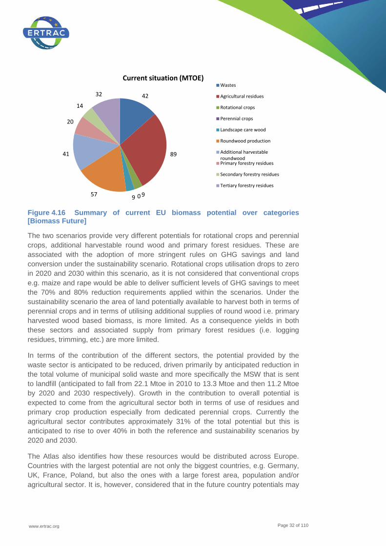
Figure 4.16 Summary of current EU biomass potential over categories [Biomass Future]
The two scenarios provide very different potentials for rotational crops and perennial crops, additional harvestable round wood and primary forest residues. These are associated with the adoption of more stringent rules on GHG savings and land conversion under the sustainability scenario. Rotational crops utilisation drops to zero in 2020 and 2030 within this scenario, as it is not considered that conventional crops e.g. maize and rape would be able to deliver sufficient levels of GHG savings to meet the 70% and 80% reduction requirements applied within the scenarios. Under the sustainability scenario the area of land potentially available to harvest both in terms of perennial crops and in terms of utilising additional supplies of round wood i.e. primary harvested wood based biomass, is more limited. As a consequence yields in both these sectors and associated supply from primary forest residues (i.e. logging residues, trimming, etc.) are more limited.
In terms of the contribution of the different sectors, the potential provided by the waste sector is anticipated to be reduced, driven primarily by anticipated reduction in the total volume of municipal solid waste and more specifically the MSW that is sent to landfill (anticipated to fall from 22.1 Mtoe in 2010 to 13.3 Mtoe and then 11.2 Mtoe by 2020 and 2030 respectively). Growth in the contribution to overall potential is expected to come from the agricultural sector both in terms of use of residues and primary crop production especially from dedicated perennial crops. Currently the agricultural sector contributes approximately 31% of the total potential but this is anticipated to rise to over 40% in both the reference and sustainability scenarios by 2020 and 2030.
The Atlas also identifies how these resources would be distributed across Europe. Countries with the largest potential are not only the biggest countries, e.g. Germany, UK, France, Poland, but also the ones with a large forest area, population and/or agricultural sector. It is, however, considered that in the future country potentials may
42
89
9 0 9 57
41
20
14
32
Current situation (MTOE) Wastes
Agricultural residues
Rotational crops
Perennial crops
Landscape care wood
Roundwood production
Additional harvestableroundwoodPrimary forestry residues
Secondary forestry residues
Tertiary forestry residues
www.ertrac.org
Page 33 of 110
shift with a decline in the contribution of big countries like Germany and Italy to the EU potential.
Conversely an increase would be expected France, Spain, Poland and Romania. Besides these; differences among relative country contributions across the scenarios are limited.
The regional distribution of the forestry potential is expected to remain stable over regions, with the largest potentials concentrated in Scandinavia, the Baltic States and France. Landscape care wood potential is expected to increase towards the future.
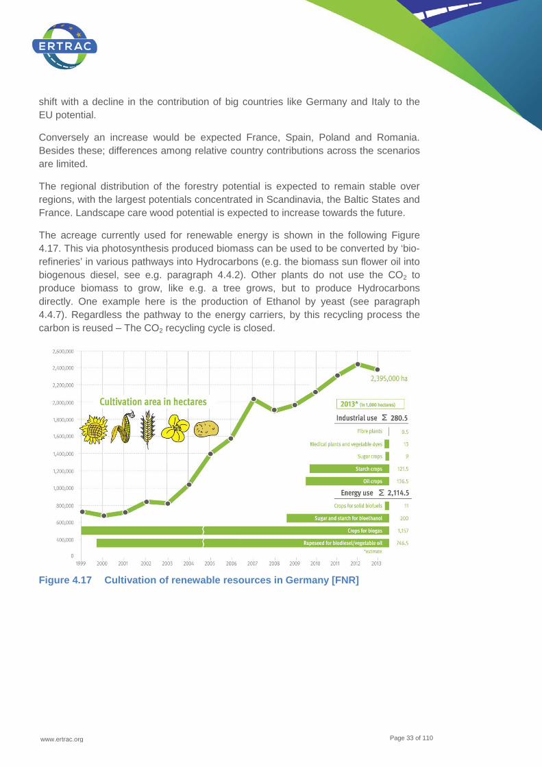
The acreage currently used for renewable energy is shown in the following Figure 4.17. This via photosynthesis produced biomass can be used to be converted by ‘bio-refineries’ in various pathways into Hydrocarbons (e.g. the biomass sun flower oil into biogenous diesel, see e.g. paragraph 4.4.2). Other plants do not use the CO2 to produce biomass to grow, like e.g. a tree grows, but to produce Hydrocarbons directly. One example here is the production of Ethanol by yeast (see paragraph 4.4.7). Regardless the pathway to the energy carriers, by this recycling process the carbon is reused – The CO2 recycling cycle is closed.
Figure 4.17 Cultivation of renewable resources in Germany [FNR]
www.ertrac.org
Page 34 of 110
Bio
mas
s re
sour
ce
Bio
mas
s so
urce
s in
clud
ed
Cur
rent
A
vaila
bilit
y
2020
Use
–
refe
renc
e sc
enar
io
2020
Use
–
sust
aina
bilit
y sc
enar
io
2030
Use
–
refe
renc
e sc
enar
io
2030
Use
–
sust
aina
bilit
y sc
enar
io
Wastes (a)
Grass cuttings, residues from food processing, biodegradable municipal waste, sludges, used fats and oils and used paper and board
42 36 36 33 33
Agricultural residues (a)
Inter alia manure, straw, other residues including prunings and cuttings from permanent crops
89 106 106 106 106
Rotational crops (b)
Crops grown meet bioenergy needs such as maize for biogas and crops used as biofuel feedstocks such as rape.
9 17 0 20 0
Perennial crops (b)
Dedicated energy crops providing lingo cellulosic material 0 58 52 49 37
Landscape care wood (a)
Residues i.e. cuttings etc. from landscaping and management activities
9 15 11 12 11
Round wood productionb
Stem wood from forests currently harvested 57 56 56 56 56
Additional harvestable roundwood (b)
Additional potential for the harvesting of stem wood within sustainable limits
41 38 35 39 36
Primary forestry residues (a)
Logging residues, early thinnings and extracted stumps 20 41 19 42 19
Secondary forestry residues (a)
Residues from the wood processing industry i.e. black liquor, sawmills and other industrial residues
14 15 15 17 17
Tertiary forestry residues (a)
Post-consumer wood waste i.e. from households, building sites
32 45 45 38 38
Total 314 429 375 411 353
Table 4.2. Biomass Potentials (Mtoe) per aggregate class based on time period and scenario16
16 (a) Denotes potential resources that could be deemed as waste materials or residues; (b) Denotes potentials based on primary production either through agriculture or forestry systems to deliver resource.
www.ertrac.org
Page 35 of 110
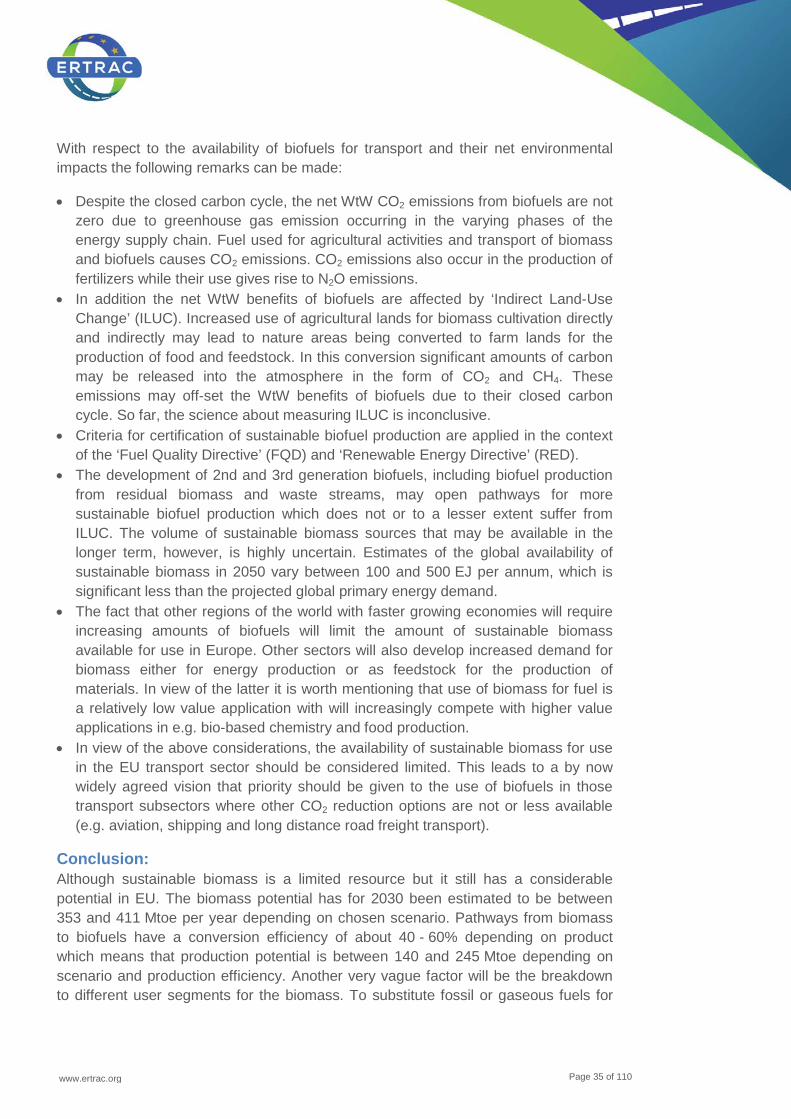
With respect to the availability of biofuels for transport and their net environmental impacts the following remarks can be made:
• Despite the closed carbon cycle, the net WtW CO2 emissions from biofuels are not zero due to greenhouse gas emission occurring in the varying phases of the energy supply chain. Fuel used for agricultural activities and transport of biomass and biofuels causes CO2 emissions. CO2 emissions also occur in the production of fertilizers while their use gives rise to N2O emissions.
• In addition the net WtW benefits of biofuels are affected by ‘Indirect Land-Use Change’ (ILUC). Increased use of agricultural lands for biomass cultivation directly and indirectly may lead to nature areas being converted to farm lands for the production of food and feedstock. In this conversion significant amounts of carbon may be released into the atmosphere in the form of CO2 and CH4. These emissions may off-set the WtW benefits of biofuels due to their closed carbon cycle. So far, the science about measuring ILUC is inconclusive.
• Criteria for certification of sustainable biofuel production are applied in the context of the ‘Fuel Quality Directive’ (FQD) and ‘Renewable Energy Directive’ (RED).
• The development of 2nd and 3rd generation biofuels, including biofuel production from residual biomass and waste streams, may open pathways for more sustainable biofuel production which does not or to a lesser extent suffer from ILUC. The volume of sustainable biomass sources that may be available in the longer term, however, is highly uncertain. Estimates of the global availability of sustainable biomass in 2050 vary between 100 and 500 EJ per annum, which is significant less than the projected global primary energy demand.
• The fact that other regions of the world with faster growing economies will require increasing amounts of biofuels will limit the amount of sustainable biomass available for use in Europe. Other sectors will also develop increased demand for biomass either for energy production or as feedstock for the production of materials. In view of the latter it is worth mentioning that use of biomass for fuel is a relatively low value application with will increasingly compete with higher value applications in e.g. bio-based chemistry and food production.
• In view of the above considerations, the availability of sustainable biomass for use in the EU transport sector should be considered limited. This leads to a by now widely agreed vision that priority should be given to the use of biofuels in those transport subsectors where other CO2 reduction options are not or less available (e.g. aviation, shipping and long distance road freight transport).
Conclusion: Although sustainable biomass is a limited resource but it still has a considerable potential in EU. The biomass potential has for 2030 been estimated to be between 353 and 411 Mtoe per year depending on chosen scenario. Pathways from biomass to biofuels have a conversion efficiency of about 40 - 60% depending on product which means that production potential is between 140 and 245 Mtoe depending on scenario and production efficiency. Another very vague factor will be the breakdown to different user segments for the biomass. To substitute fossil or gaseous fuels for

www.ertrac.org
Page 36 of 110
mobility there is a potential between 15% and 30% for biofuels. Herein the residuals as feedstock (see Table 4.2 and Figure 4.16) have the most significant influence. Biomass resources set aside for other needs may alter the potential considerably and therefore the biofuels will under all circumstances reach a limit and will not substitute fossil based fuels in total (see Figure 2.1).
Biofuels will play a very important role to decarbonise the energy carries for mobility but they will not substitute fossil energy in total.
4.4 Renewable liquid fuels
In the following chapter the various pathway to liquid fuels are described. Before entering into the pathways ‘Drop-In’ fuels are defined.
Definition of ‘Drop-In Fuels’ So called ‘Drop-In Fuels’ are fuels, which overcome the challenges of state of the art biofuels, enabling high concentration blends compatible with current vehicles or infrastructure. E.g. ethanol and FAME are not “drop-in fuels”. The main challenges to be solved are:
• Compatibility with infrastructure • Compatibility with vehicles • Sustainability
A ‘Drop-In Fuel’ needs to meet the sustainability criteria (including 60% GHG reduction for new manufacturing plants), is not produced from food (cereals and other starches, sugars, oil crops) and includes biofuels produced from the waste, residue and lignocellulosic feedstocks listed in Annex IX in the proposed amendment to the RED.
The compatibility does not need to be met for the pure / neat bio fuel. Due to the potential of biomass based renewable fuels an overall substitution < 30% is achievable (compare to Figure 4.16 and Figure 4.17). Alongside a European wide harmonised fuel quality standard a drop-in-fuel ‘only’ need to fulfil the compatibility challenge up to a level of approximately 30%.
The drop-in fuel needs to be backwardly compatible with the existing fleet and infrastructure. Due to the good quality (e.g. of HVO, see paragraph 4.1.1) the combustion process might be optimised to achieve higher efficiencies with new introduced and optimised vehicles.
4.4.1 Hydro treated (vegetable) oils and fats (HVO) and Hydrotreated Esters (HEFA)
Hydrotreated vegetable oil which can be made also from waste animal fats or new alternative oil production pathways is a paraffinic diesel fuel close to ‘gas to liquid’ (GtL) and ‘Biomass to liquid’ (BtL) in terms of chemical composition and physical

www.ertrac.org
Page 37 of 110
properties, compare to paragraph 4.4.2. HVO can be blended, as a drop-in fuel, without a fixed ‘blending wall’ into EN 590 diesel fuel. In practice the maximum amount is defined case by case from the lower density limit of EN 590 since HVO in a blend reduces density. Up to about 30% blending ratios have been used until now, and up to 100% in technically adapted, captured fleets.
HVO with its paraffinic nature, reasonable distillation range, very low amount of ash forming components, high cetane number and good winter properties, achievable thank to hydro-isomerisation production step and is consequently a very suitable fuel to be used in diesel engines. It fits for old, existing and future engines as well as for different exhaust aftertreatment systems. One diesel fuel type with remarkable share of HVO fits for everyone without any need for separate ‘protection grade’ fuel like E5 today and obviously E10 in the future for part of the existing otto-engined car park. HVO can be delivered for consumers through the existing diesel fuel logistic system without any additional challenges.
HVO can be used as such in the current diesel engine technology, when the lubricity is balanced by adequate additives. However, a validation may be needed in order to meet regulatory exhaust requirements and warranty liabilities. If engine and exhaust aftertreatment systems are tuned especially for HVO, additional benefits in fuel economy and tailpipe emissions can be obtained. This will give an opportunity to design ‘Diesel-FFV’ -vehicles like otto-FFV-engines today for mixtures of gasoline and 85% ethanol.
HVO's energy content is even slightly higher per kg than of fossil diesel fuel. Due to the lower density energy content is slightly lower per liter but in any case, the best of all renewable fuels together with BtL. This means that the current storage tank and vehicle fuel tank sizes as well as the wide driving range of diesel vehicles can be maintained. When taking also engine efficiency into account a certain volume of HVO propels a vehicle about double mileage compared to ethanol.
Quality of HVO is defined by CEN TS 15940:2012 which will be updated to a formal EN 15940 standard according to CEN's procedures.
HVO production technology is ready and used in large commercial scale over one million tons in Europe. Technology is in many respects similar to catalytic processes used in traditional oil refining, and it is available from many process technology suppliers. Regarding know-how, logistics and utilities HVO production fits well to be built in connection with current oil refineries.
Main product of an HVO process is diesel fuel and in addition to that some volumes of aviation kerosene can be produced. Minor amounts of renewable hydrocarbon gasoline and renewable LPG are produced as side products.
Renewable origin resembling HVO can be added into fossil fuel also by using so called co-feed where renewable and fossil feedstock are used as a blend into a
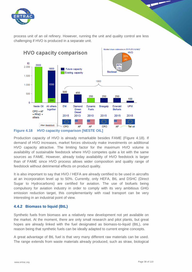
www.ertrac.org
Page 38 of 110
process unit of an oil refinery. However, running the unit and quality control are less challenging if HVO is produced in a separate unit.
Figure 4.18 HVO capacity comparison [NESTE OIL]
Production capacity of HVO is already remarkable besides FAME (Figure 4.18). If demand of HVO increases, market forces obviously make investments on additional HVO capacity attractive. The limiting factor for the maximum HVO volume is availability of sustainable feedstock where HVO competes quite a lot with the same sources as FAME. However, already today availability of HVO feedstock is larger than of FAME since HVO process allows wider composition and quality range of feedstock without detrimental effects on product quality.
It is also important to say that HVO / HEFA are already certified to be used in aircrafts at an incorporation level up to 50%. Currently, only HEFA, BtL and DSHC (Direct Sugar to Hydrocarbons) are certified for aviation. The use of biofuels being compulsory for aviation industry in order to comply with its very ambitious GHG emission reduction target, this complementarity with road transport can be very interesting in an industrial point of view.
4.4.2 Biomass to liquid (BtL)
Synthetic fuels from biomass are a relatively new development not yet available on the market. At the moment, there are only small research and pilot plants, but great hopes are already linked with the fuel designated as biomass-to-liquid (BtL), one reason being that synthetic fuels can be ideally adapted to current engine concepts.
A great advantage of BtL fuel is that very many different raw materials can be used. The range extends from waste materials already produced, such as straw, biological
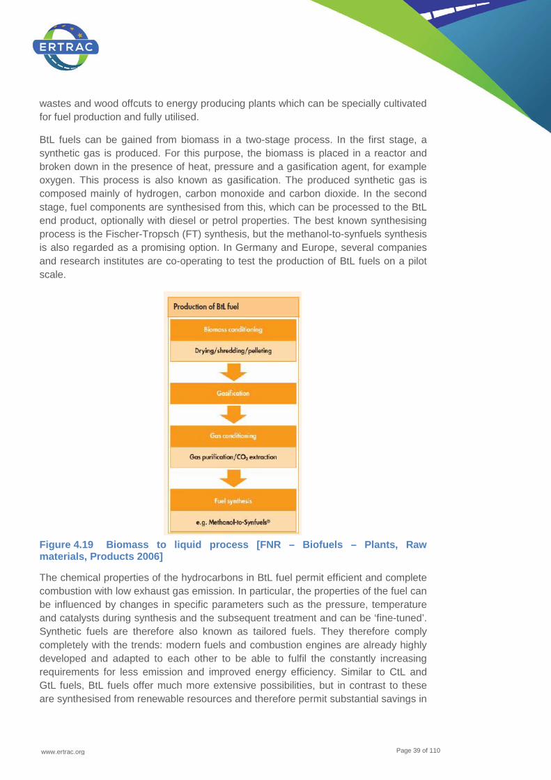
www.ertrac.org
Page 39 of 110
wastes and wood offcuts to energy producing plants which can be specially cultivated for fuel production and fully utilised.
BtL fuels can be gained from biomass in a two-stage process. In the first stage, a synthetic gas is produced. For this purpose, the biomass is placed in a reactor and broken down in the presence of heat, pressure and a gasification agent, for example oxygen. This process is also known as gasification. The produced synthetic gas is composed mainly of hydrogen, carbon monoxide and carbon dioxide. In the second stage, fuel components are synthesised from this, which can be processed to the BtL end product, optionally with diesel or petrol properties. The best known synthesising process is the Fischer-Tropsch (FT) synthesis, but the methanol-to-synfuels synthesis is also regarded as a promising option. In Germany and Europe, several companies and research institutes are co-operating to test the production of BtL fuels on a pilot scale.
Figure 4.19 Biomass to liquid process [FNR – Biofuels – Plants, Raw materials, Products 2006]
The chemical properties of the hydrocarbons in BtL fuel permit efficient and complete combustion with low exhaust gas emission. In particular, the properties of the fuel can be influenced by changes in specific parameters such as the pressure, temperature and catalysts during synthesis and the subsequent treatment and can be ‘fine-tuned’. Synthetic fuels are therefore also known as tailored fuels. They therefore comply completely with the trends: modern fuels and combustion engines are already highly developed and adapted to each other to be able to fulfil the constantly increasing requirements for less emission and improved energy efficiency. Similar to CtL and GtL fuels, BtL fuels offer much more extensive possibilities, but in contrast to these are synthesised from renewable resources and therefore permit substantial savings in

www.ertrac.org
Page 40 of 110
climate gas emission. BtL fuel is a drop-in fuel and can be used without major technical modifications to the engine and logistics is possible using the existing infrastructure.
Moreover, as said above for the HVO pathway, a great synergy exists between road and air transport for this type of product.
4.4.3 Dimethyl Ether (DME)
The current key markets for DME as a fuel are (1) LPG blend stock; (2) transportation fuel as diesel substitute; (3) fuel for power generation using gas turbines; and (4) chemical intermediate for olefins and gasoline production.
DME is an environmentally benign, non-toxic, biodegradable product with physical properties similar to LPG, with very low soot combustion properties. Global DME annual production capacity is approximately 10 million metric tons and actual market use is reported to be about 3 million metric tons (2011)
Figure 4.20 Molecule structure DME, Methanol and Methane (Black= Carbon, Red= Oxygen, White=Hydrogen) [Volvo]
DME is a synthetic fuel that can be produced in number of pathways, with both fossil and renewable feedstock.
DME is primarily produced by converting hydrocarbons sourced from natural gas or coal via gasification to synthesis gas (syngas). Synthesis gas is then converted into methanol in the presence of catalyst (usually copper-based), with subsequent methanol dehydration in the presence of a different catalyst (for example, silica-alumina) resulting in the production of DME. As described, this is a two-step (indirect synthesis) process that starts with methanol synthesis and ends with DME synthesis (methanol dehydration). The same process can be conducted using organic waste or biomass.
DME can be produced from natural gas via gasification. Natural gas is increasingly important as primary energy source. DME can be produced from natural gas either directly or via methanol with subsequent dehydration to DME.
DME from coal: In China, DME is produced from coal derived methanol.
DME from methanol: When producing DME with conventional processes methanol is an intermediate product that in a second stage under moderate process conditions and at moderate investment cost is dehydrated to form DME:
www.ertrac.org
Page 41 of 110
2CH3OH C2H6O + H2O (Methanol DME + Water)
This fact can be utilized to sub-divide the value chain so that methanol produced in one or several existing conventional and/or biomass-based methanol plants is transported to the targeted DME market and there converted into DME in a local dehydration plant. In this way a considerable flexibility in supply and a reduction of investment and logistics costs can be achieved, multiple feedstock sources could be used, as e.g.:
• Low cost natural bas based methanol • Low GHG emissions renewable methanol
DME from gasification of biomass: Several studies have shown that DME is one of the best scoring alternatives for alternative fuels. DME from gasification, either direct gasification or via black liquor gives very high GHG reduction and is energy efficient.
Gasification is key technology to efficient use of biomass, and large potential. It also enables use of non-crops based biomass. Furthermore, when producing energy carriers from synthesis gas it is advantageous to produce monomers such as DME, methanol and methane. The processes for these chemicals are highly selective compared to processes that produce hydrocarbons such as the Fisher-Tropsch process. The FT-processes produces all types of hydrocarbons from light to heavy ones and therefore additional process steps are needed in order to reach a final usable product. The FT process is also more strongly exothermal lowering the overall conversion efficiency. Comparisons between single-molecule processes, including methanol and DME, and FT-processes are available in literature, e.g. the EUCAR/CONCAWE/JRC well-to-tank study from 2007.
DME from wood + renewable electricity: When gasifying biomass, a concentrated stream of renewable CO2 is available and a combination with hydrogen produced from renewable electricity can further enhance the environmental benefit, by producing more DME from the CO2 and the hydrogen.
DME from CO2 capture + renewable electricity (electrolysis): In the future, the DME could be produced from captured CO2 and hydrogen from electrolysis.
DME is a gas at atmospheric pressure, boiling point is minus 25°C, but it condenses to a liquid at low pressure 5,1 bar @ 20°C. Physical properties and handling are very similar to LPG. DME has been commercially used as a high-grade propellant for various health care products, and its ‘environmental, health and safety’ (EHS) characteristics are rather ‘impeccable’ (vs. conventional petroleum-based fuels). DME is a flammable, thermally stable liquid like LPG and can be handled like LPG with similar safety guidelines and codes as LPG.
LPG infrastructure for vehicle fuel currently exists in many countries in the world. The same technology can be used for DME with only minor modifications, mainly change to DME compatible sealing materials.
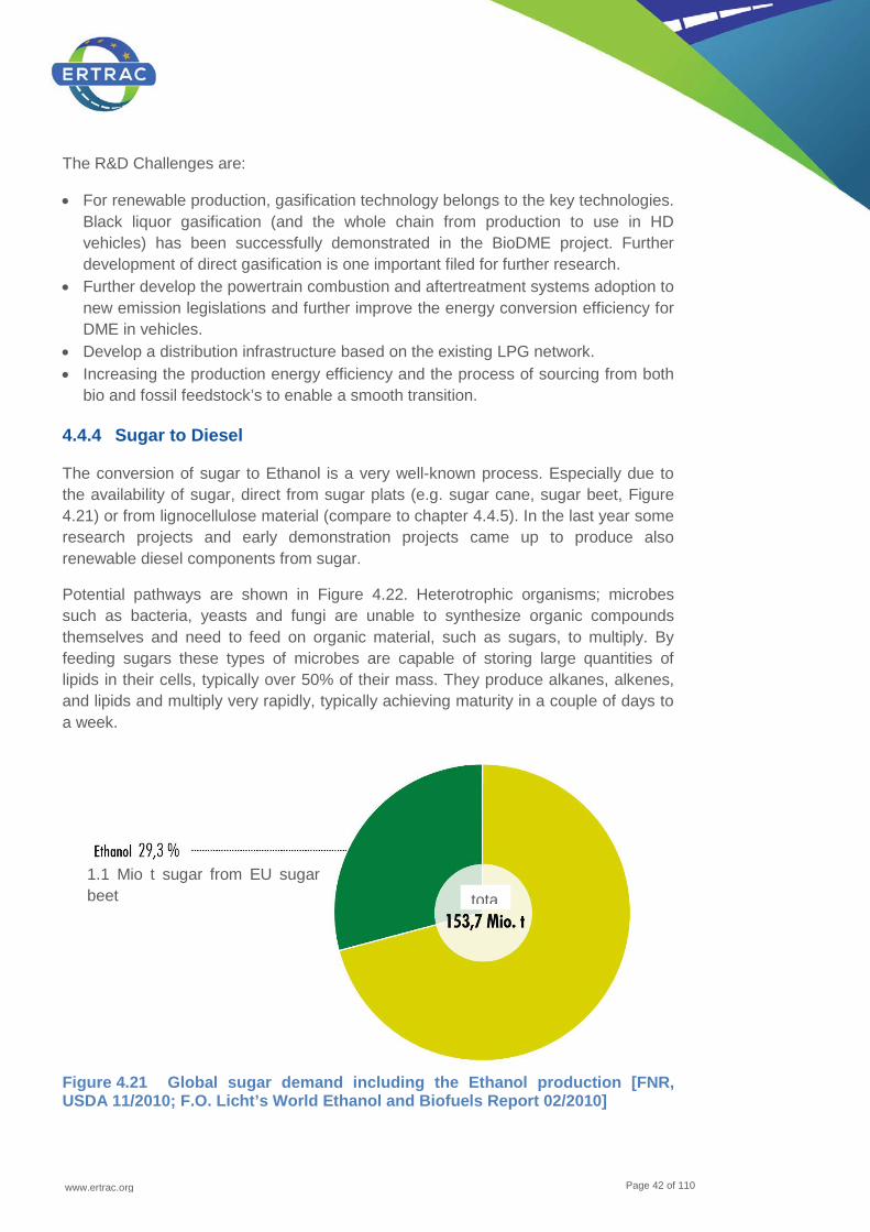
www.ertrac.org
Page 42 of 110
The R&D Challenges are:
• For renewable production, gasification technology belongs to the key technologies. Black liquor gasification (and the whole chain from production to use in HD vehicles) has been successfully demonstrated in the BioDME project. Further development of direct gasification is one important filed for further research.
• Further develop the powertrain combustion and aftertreatment systems adoption to new emission legislations and further improve the energy conversion efficiency for DME in vehicles.
• Develop a distribution infrastructure based on the existing LPG network. • Increasing the production energy efficiency and the process of sourcing from both
bio and fossil feedstock’s to enable a smooth transition.
4.4.4 Sugar to Diesel
The conversion of sugar to Ethanol is a very well-known process. Especially due to the availability of sugar, direct from sugar plats (e.g. sugar cane, sugar beet, Figure 4.21) or from lignocellulose material (compare to chapter 4.4.5). In the last year some research projects and early demonstration projects came up to produce also renewable diesel components from sugar.
Potential pathways are shown in Figure 4.22. Heterotrophic organisms; microbes such as bacteria, yeasts and fungi are unable to synthesize organic compounds themselves and need to feed on organic material, such as sugars, to multiply. By feeding sugars these types of microbes are capable of storing large quantities of lipids in their cells, typically over 50% of their mass. They produce alkanes, alkenes, and lipids and multiply very rapidly, typically achieving maturity in a couple of days to a week.
Figure 4.21 Global sugar demand including the Ethanol production [FNR, USDA 11/2010; F.O. Licht’s World Ethanol and Biofuels Report 02/2010]
1.1 Mio t sugar from EU sugar beet
tota
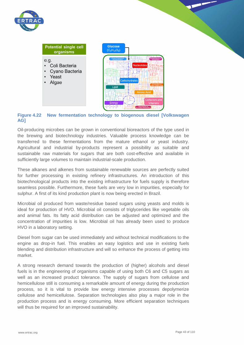
www.ertrac.org
Page 43 of 110
Figure 4.22 New fermentation technology to biogenous diesel [Volkswagen AG]
Oil-producing microbes can be grown in conventional bioreactors of the type used in the brewing and biotechnology industries. Valuable process knowledge can be transferred to these fermentations from the mature ethanol or yeast industry. Agricultural and industrial by-products represent a possibility as suitable and sustainable raw materials for sugars that are both cost-effective and available in sufficiently large volumes to maintain industrial-scale production.
These alkanes and alkenes from sustainable renewable sources are perfectly suited for further processing in existing refinery infrastructures. An introduction of this biotechnological products into the existing infrastructure for fuels supply is therefore seamless possible. Furthermore, these fuels are very low in impurities, especially for sulphur. A first of its kind production plant is now being erected in Brazil.
Microbial oil produced from waste/residue based sugars using yeasts and molds is ideal for production of HVO. Microbial oil consists of triglycerides like vegetable oils and animal fats. Its fatty acid distribution can be adjusted and optimized and the concentration of impurities is low. Microbial oil has already been used to produce HVO in a laboratory setting.
Diesel from sugar can be used immediately and without technical modifications to the engine as drop-in fuel. This enables an easy logistics and use in existing fuels blending and distribution infrastructure and will so enhance the process of getting into market.
A strong research demand towards the production of (higher) alcohols and diesel fuels is in the engineering of organisms capable of using both C6 and C5 sugars as well as an increased product tolerance. The supply of sugars from cellulose and hemicellulose still is consuming a remarkable amount of energy during the production process, so it is vital to provide low energy intensive processes depolymerize cellulose and hemicellulose. Separation technologies also play a major role in the production process and is energy consuming. More efficient separation techniques will thus be required for an improved sustainability.
www.ertrac.org
Page 44 of 110
4.4.5 Advanced sugar to Ethanol (or higher alcohols) pathways
Glucose, as one molecule from the wide field of sugars, is a ubiquitous found mostly as a polymer in cellulose and hemicellulose. Glucose metabolism can be found in nearly any form of organisms and is leading to the same intermediates, which can be coupled by modern biology to virtually any type of product. Amongst them is the formation of alcohols, especially ethanol. Ethanol formation is among the oldest and best surveyed biotechnological processes for mankind.
The technology thus is established in industrial scale and spread out worldwide. Ethanol is produced currently mainly on basis of e.g. corn, wheat or sugar beet, with cellulosic ethanol being now introduced in industrial scale. Furthermore, butanol and its isomers are also very interesting fuel components. Especially for butanol, an increasing number of companies are investing due to its interesting properties. Butanol formation is achieved nowadays through fermentation by specially adapted microorganisms.
Butanol can be introduced into existing gasoline fuels already today within the boundaries of current European and U.S. specifications. Its production processes using sugars from sustainable, renewable sources or even waste streams are highly attractive for fuels with reduced carbon footprint. Enabling an Ethanol industry on the basis of cellulosic sugars is enabling butanol production from these sources.
Higher alcohols including pentanol and its isomers upwards have not been proven today in a semi-technical or technical scale. For these alcohols, all the advantages for butanol compared to ethanol will also be in place. With an ever increasing C-number, one must take into account that these molecules will show rising CFPP and CP as well as increasing melting points. At the same time the acidity is decreasing.
A strong research demand towards the production of (higher) alcohols is in the engineering of organisms capable of using both C6 and C5 sugars as well as an increased product tolerance. The supply of sugars from cellulose and hemicellulose still is consuming a remarkable amount of energy during the production process, so it is vital to provide low energy intensive processes depolymerize cellulose and hemicellulose. Separation technologies also play a major role in the production process and is energy consuming. More efficient separation techniques will thus be required for an improved sustainability.
4.4.6 Algae to liquid technologies
Algae are a very large and diverse group of unicellular and multicellular atrophic organisms. Particularly microalgae got into the focus of the biofuel industry because of their high lipid content and very fast growth rates. It has been estimated that microalgae could produce between 25 - 30 t oil per hectare and year, which could be used as basis for the production of biodiesel and kerosene. The yield depends on the

www.ertrac.org
Page 45 of 110
strain’s genetics, the growth method, assess to key nutrients and location (Rösch & Posten, 2012). Theoretical calculations show attractive potential for future algae –based biofuels.
Since the 1950s algae have been grown commercially to produce fish food, human food additives and pigments. In the past, industrial application of algae has focused solely on high-value products. Algae technology is becoming more and more prominent. Algae are seen as alternative resource with increasing importance for the production of biofuels. However, the viability of the involved production and conversion processes are strongly connected to further development and increasing efficiency of algae biotechnology.
The production pathways of drop-in fuels from algae oil follow similar production pathways as other biofuels pathways using e.g. vegetable oils as feedstocks. However, different measures have to be applied to harvest the algae biomass in the first place (e.g. centrifugation, sedimentation and filtration) and to extract the oil from the algae (e.g. using organic solvents or supercritical CO2). Depending of the algae species, the oil will be characterized by a high degree of unsaturation, which will cause problems in the production process of biodiesel if the unsaturated fatty acids are not at least partially saturated beforehand. For the conversion into biodiesel the lipids need to undergo two processes: esterification and hydrogenenation. About twelve kg of dry algal biomass are needed to produce 1 kg biodiesel (Petkov, et al., 2011).
Today, using algae exclusively for energy purposes is economically not viable. The synergetic combination of industrial and energetic uses of algae in a bio refinery approach will become more important in the future.
The R&D needs of algae as drop-in fuels cover the full range of topics from basic biology to engineering.
• The ecology of algae, their lipid productivity and composition, growth rates and growth control have to be developed and optimized. This does not only refer to yield rates and strain improvement towards a desired fatty acid profile but also to increased tolerance of contaminants.
• Scale up is a critical issue for algae fuel production. • Ongoing research and cost reduction of efficient cultivation reactors is of
importance. • Low-cost, high-efficiency algae cultivation technology needs to be developed for
large scale algae production. • The energy balance of cultivation, harvesting and oil extraction must be improved. • Facilitation of sustainable cost-competitiveness of algae- fuels. This needs to
include identifying algae species with high oil contents and with higher yields, but also developing and optimising different steps in the cultivation process.

www.ertrac.org
Page 46 of 110
Further R&D needs to ensure a whole value-chain approach, which takes economic, socials, environmental and technological, as well as bio refining and LCA into account.
Microalgae of microscopic size can be grown in seawater and on land unsuitable for cultivation. Microalgae produce sugars, lipids, and proteins from CO2, water, and nutrients using photosynthesis. They can make use of the nutrients contained in wastewater, for example. As they also bind CO2, they also offer a number of exciting possibilities in helping us meet tomorrow’s energy needs. Under favourable conditions, microalgae can produce lipids year-round, and offer a dramatically higher production potential than oil plants.
Microalgae are seen as the origin of the world’s crude oil. They grow within a few days, and most species produce intracellular lipids. Tens of thousands of different species exist, and can be found wherever water and light is available. These unicellular organisms can divide as often as several times a day and normally double their biomass in one to three days.
Lipids from algae are suitable for raw material for HVO production. Current constraint is that microalgae are not yet grown at an industrial scale for biofuel production.
4.4.7 Biotechnological fuel production
The idea of biotechnological fuel production originates from the thousands of years old principle of microbial fermentation of sugar-rich raw materials. The microorganism itself represents the central conversion unit, e.g. eukaryotes like yeast, prokaryotes like bacteria (Escherichia coli) and archaea bacteria, could act as a little factories. Within a cell multiple synthesis steps occur, numerous subsequent chemical reactions which convert the nutrition material via metabolic pathways into various products, as the cell needs to multiply itself and assembles energy from the substrate. In the case of the yeast the cell metabolises sugar performing cell-internal fermentation and produces ethanol as product.
Ethanol represents a suitable fuel component and can be fuelled into gasoline automotive combustion engines. From this start point the idea of microbial fuel production extends to the target of a designed biofuel production to get a variety of gasoline and diesel fuel compatible components which offer the potential of biofuel production.
At present the concept of photosynthetic direct fuel production gets into the focus of science and industry. Photosynthetic microorganisms are able to collect solar radiation (sunlight) and take up carbon dioxide as nutrient and convert them into components which show compatibility as fuel, see Figure 4.23. For the collection of the sunlight the photosynthetic microorganisms like cyanobacteria and algae have either so-called light antenna or chloroplasts as embodiments in the cell. The photosynthesis precedes the conversion to chemical energy which the cell uses in metabolic pathways to synthesize products. For example cyanobacteria transform the
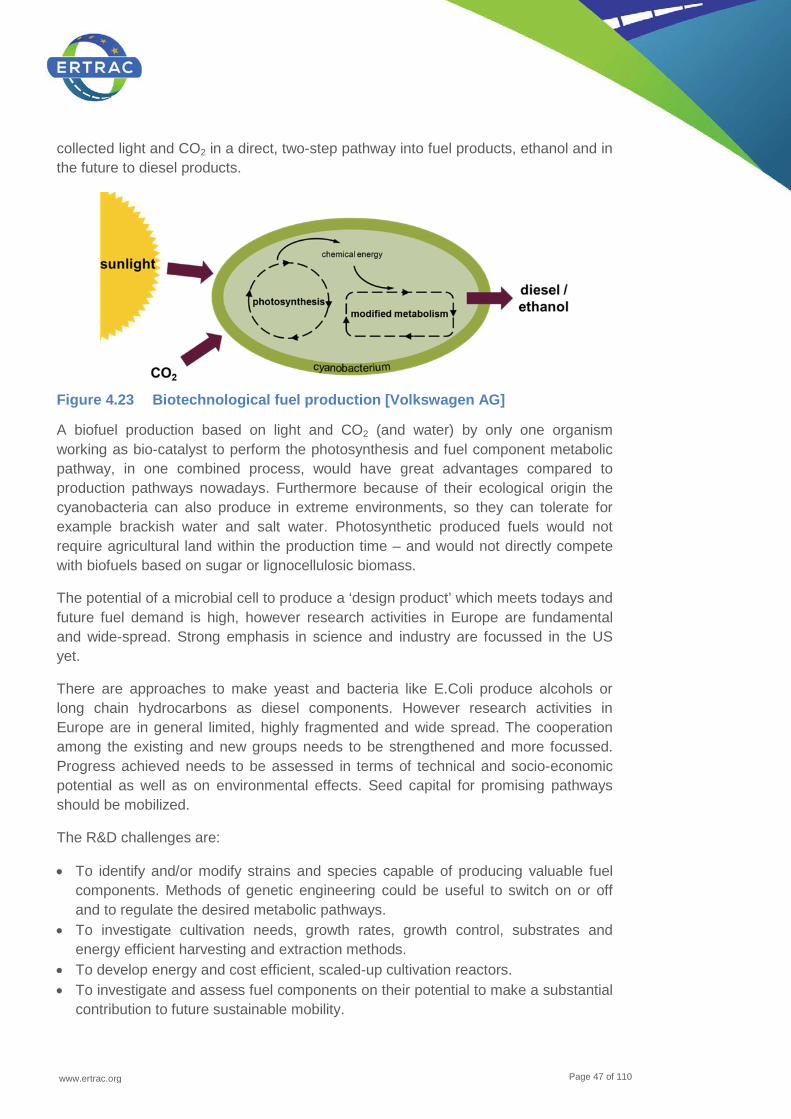
www.ertrac.org
Page 47 of 110
collected light and CO2 in a direct, two-step pathway into fuel products, ethanol and in the future to diesel products.
Figure 4.23 Biotechnological fuel production [Volkswagen AG]
A biofuel production based on light and CO2 (and water) by only one organism working as bio-catalyst to perform the photosynthesis and fuel component metabolic pathway, in one combined process, would have great advantages compared to production pathways nowadays. Furthermore because of their ecological origin the cyanobacteria can also produce in extreme environments, so they can tolerate for example brackish water and salt water. Photosynthetic produced fuels would not require agricultural land within the production time – and would not directly compete with biofuels based on sugar or lignocellulosic biomass.
The potential of a microbial cell to produce a ‘design product’ which meets todays and future fuel demand is high, however research activities in Europe are fundamental and wide-spread. Strong emphasis in science and industry are focussed in the US yet.
There are approaches to make yeast and bacteria like E.Coli produce alcohols or long chain hydrocarbons as diesel components. However research activities in Europe are in general limited, highly fragmented and wide spread. The cooperation among the existing and new groups needs to be strengthened and more focussed. Progress achieved needs to be assessed in terms of technical and socio-economic potential as well as on environmental effects. Seed capital for promising pathways should be mobilized.
The R&D challenges are:
• To identify and/or modify strains and species capable of producing valuable fuel components. Methods of genetic engineering could be useful to switch on or off and to regulate the desired metabolic pathways.
• To investigate cultivation needs, growth rates, growth control, substrates and energy efficient harvesting and extraction methods.
• To develop energy and cost efficient, scaled-up cultivation reactors. • To investigate and assess fuel components on their potential to make a substantial
contribution to future sustainable mobility.
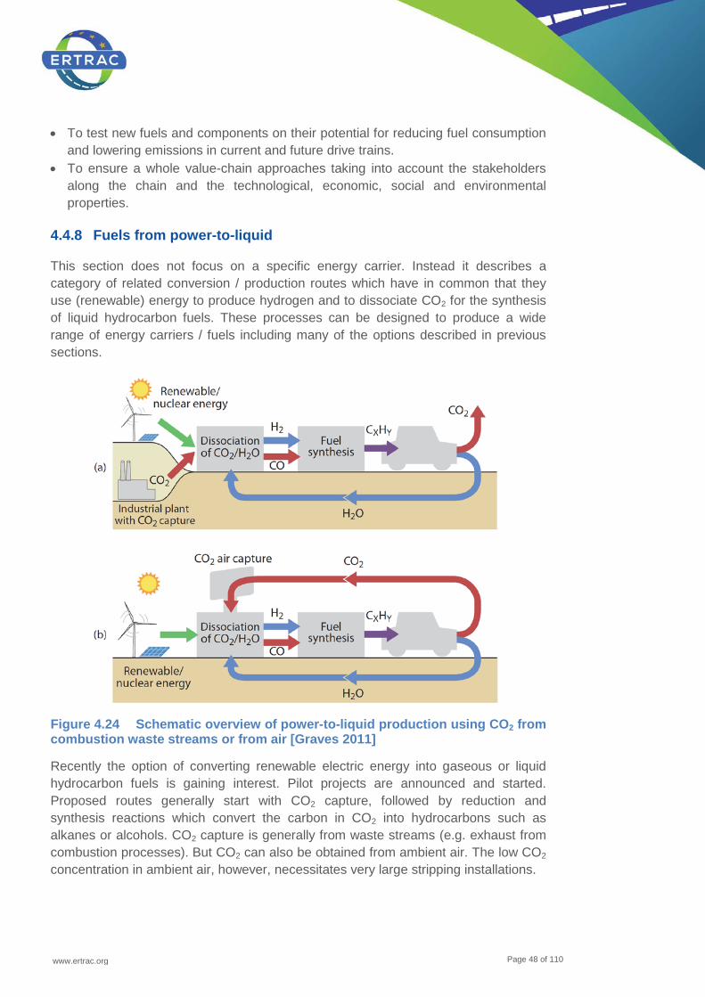
www.ertrac.org
Page 48 of 110
• To test new fuels and components on their potential for reducing fuel consumption and lowering emissions in current and future drive trains.
• To ensure a whole value-chain approaches taking into account the stakeholders along the chain and the technological, economic, social and environmental properties.
4.4.8 Fuels from power-to-liquid
This section does not focus on a specific energy carrier. Instead it describes a category of related conversion / production routes which have in common that they use (renewable) energy to produce hydrogen and to dissociate CO2 for the synthesis of liquid hydrocarbon fuels. These processes can be designed to produce a wide range of energy carriers / fuels including many of the options described in previous sections.
Figure 4.24 Schematic overview of power-to-liquid production using CO2 from combustion waste streams or from air [Graves 2011]
Recently the option of converting renewable electric energy into gaseous or liquid hydrocarbon fuels is gaining interest. Pilot projects are announced and started. Proposed routes generally start with CO2 capture, followed by reduction and synthesis reactions which convert the carbon in CO2 into hydrocarbons such as alkanes or alcohols. CO2 capture is generally from waste streams (e.g. exhaust from combustion processes). But CO2 can also be obtained from ambient air. The low CO2 concentration in ambient air, however, necessitates very large stripping installations.
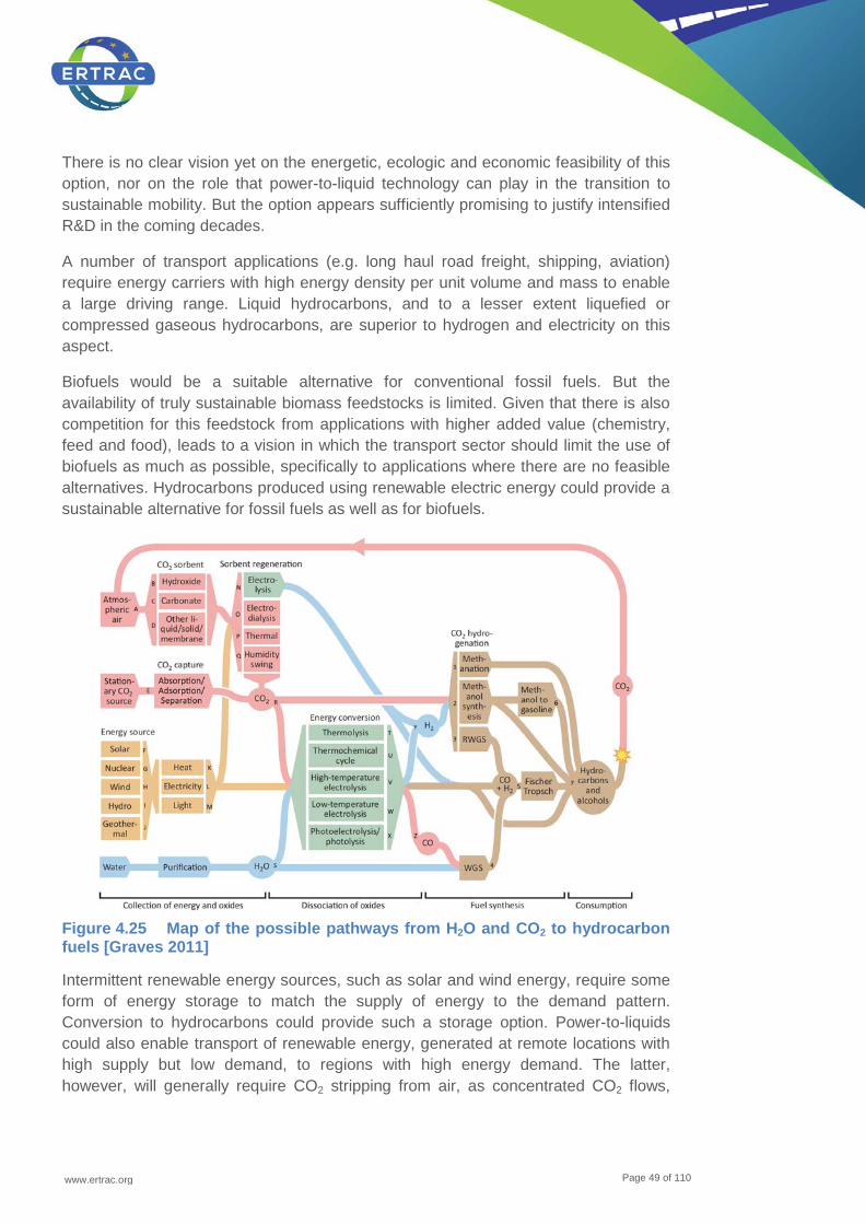
www.ertrac.org
Page 49 of 110
There is no clear vision yet on the energetic, ecologic and economic feasibility of this option, nor on the role that power-to-liquid technology can play in the transition to sustainable mobility. But the option appears sufficiently promising to justify intensified R&D in the coming decades.
A number of transport applications (e.g. long haul road freight, shipping, aviation) require energy carriers with high energy density per unit volume and mass to enable a large driving range. Liquid hydrocarbons, and to a lesser extent liquefied or compressed gaseous hydrocarbons, are superior to hydrogen and electricity on this aspect.
Biofuels would be a suitable alternative for conventional fossil fuels. But the availability of truly sustainable biomass feedstocks is limited. Given that there is also competition for this feedstock from applications with higher added value (chemistry, feed and food), leads to a vision in which the transport sector should limit the use of biofuels as much as possible, specifically to applications where there are no feasible alternatives. Hydrocarbons produced using renewable electric energy could provide a sustainable alternative for fossil fuels as well as for biofuels.
Figure 4.25 Map of the possible pathways from H2O and CO2 to hydrocarbon fuels [Graves 2011]
Intermittent renewable energy sources, such as solar and wind energy, require some form of energy storage to match the supply of energy to the demand pattern. Conversion to hydrocarbons could provide such a storage option. Power-to-liquids could also enable transport of renewable energy, generated at remote locations with high supply but low demand, to regions with high energy demand. The latter, however, will generally require CO2 stripping from air, as concentrated CO2 flows,
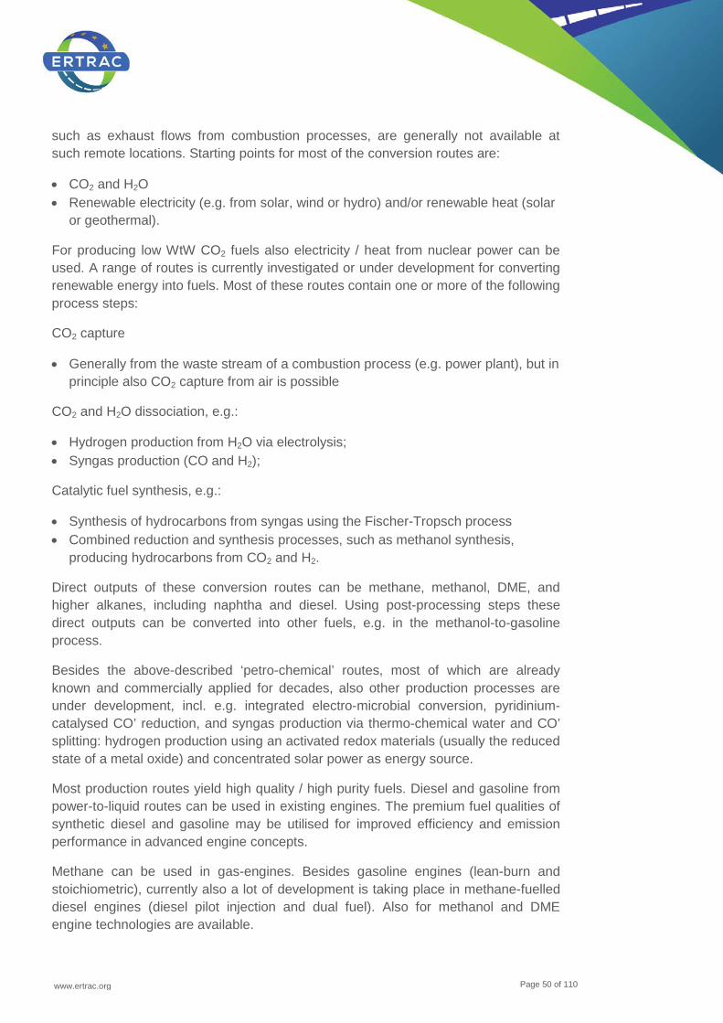
www.ertrac.org
Page 50 of 110
such as exhaust flows from combustion processes, are generally not available at such remote locations. Starting points for most of the conversion routes are:
• CO2 and H2O • Renewable electricity (e.g. from solar, wind or hydro) and/or renewable heat (solar
or geothermal).
For producing low WtW CO2 fuels also electricity / heat from nuclear power can be used. A range of routes is currently investigated or under development for converting renewable energy into fuels. Most of these routes contain one or more of the following process steps:
CO2 capture
• Generally from the waste stream of a combustion process (e.g. power plant), but in principle also CO2 capture from air is possible
CO2 and H2O dissociation, e.g.:
• Hydrogen production from H2O via electrolysis; • Syngas production (CO and H2);
Catalytic fuel synthesis, e.g.:
• Synthesis of hydrocarbons from syngas using the Fischer-Tropsch process • Combined reduction and synthesis processes, such as methanol synthesis,
producing hydrocarbons from CO2 and H2.
Direct outputs of these conversion routes can be methane, methanol, DME, and higher alkanes, including naphtha and diesel. Using post-processing steps these direct outputs can be converted into other fuels, e.g. in the methanol-to-gasoline process.
Besides the above-described ‘petro-chemical’ routes, most of which are already known and commercially applied for decades, also other production processes are under development, incl. e.g. integrated electro-microbial conversion, pyridinium-catalysed CO’ reduction, and syngas production via thermo-chemical water and CO’ splitting: hydrogen production using an activated redox materials (usually the reduced state of a metal oxide) and concentrated solar power as energy source.
Most production routes yield high quality / high purity fuels. Diesel and gasoline from power-to-liquid routes can be used in existing engines. The premium fuel qualities of synthetic diesel and gasoline may be utilised for improved efficiency and emission performance in advanced engine concepts.
Methane can be used in gas-engines. Besides gasoline engines (lean-burn and stoichiometric), currently also a lot of development is taking place in methane-fuelled diesel engines (diesel pilot injection and dual fuel). Also for methanol and DME engine technologies are available.

www.ertrac.org
Page 51 of 110
Open questions and research topics for this technology are:
• WtW energy efficiency assessment and GHG emissions of the various routes [Graves 2011] states that an overall electricity-to-fuel efficiency of 70% can be reached with current state-of-the-art technology and sufficient system integration.
• Analyses of other process energy inputs besides electricity. How can these process energy inputs be obtained from renewable sources (e.g. solar power)?
• Analyse of overall costs for producing power-to-liquids • Assessments by [Graves 2011] indicate that at current European gasoline prices of
around 1 €/litre excl. tax, the power-to-liquid production of synthetic gasoline could be competitive at an electricity price of 0.08 €/kWh. This is generally lower than the costs of renewable electricity.
• What are the possibilities for using power-to-liquids to resolve short term (daily / weekly) and long-term (seasonal) mismatches between the supply or intermittent renewables and energy demand, and how does this application affect the overall costs?
• Using excess renewables reduces the costs of energy, but also leads to underutilisation of production plants as they can only run at full capacity when excess renewables are available.
The R&D issues for power-to-liquids are:
• Efficiency improvement of CO2-capture processes; • Efficiency improvement of electrolysis, e.g. by using solid oxide electrolysis cell
stacks at high current densities, and improving capabilities of these systems for intermittent operation;
• Development of alternative options for H2 production (e.g. increase the efficiency thermo-chemical water and CO2 splitting routes)
• Sustainable production of required process heat; • Gas cleaning technologies for CO2 capture and syngas production; • Further improvement of synthesis processes (costs, efficiency, composition of
outputs); • Energetic system integration within conversion routes; • Energetic system integration of conversion routes with other industrial processes
to optimise the use of waste energy flows; • Insight in impact of use of excess renewable energy on the cost competitiveness of
power-to-liquid routes; • Depending on the fuel produced there are limited or no R&D needs on the side of
engines / powertrains.
4.4.9 Methyl-tertiary-butyl ether (MTBE) and Methanol
Methyl-tert-butyl ether (MTBE) is a blend component of gasoline fuel. MTBE has a high octane number, which improves the knocking behaviour. MTBE is manufactured via the chemical reaction of methanol and isobutylene.

www.ertrac.org
Page 52 of 110
With the chemical structure CH3OH, methanol is the simplest alcohol, with the lowest carbon content and highest hydrogen content of any liquid fuel.
As a basic alcohol, methanol is today a transportation fuel due to its efficient combustion, ease of distribution and high level of availability around the globe. Methanol is used today in transportation in three main ways:
• Directly as fuel or blended with gasoline in captured fleets and niche markets, • Converted in dimethyl ether (DME) to be used as a diesel replacement, • Converted to MTBE, • As a part of the biodiesel production process.
Methyl-tert-butyl ether (MTBE) is a blend component of gasoline fuel. MTBE has a high octane number, which improves the knocking behaviour. MTBE is manufactured via the chemical reaction of methanol and isobutylene.
Methanol is a liquid fuel that is currently made from a number of different feedstock resources - natural gas and coal as well as renewable resources like wood or agricultural waste as well as even directly from CO2 captured from power plant and factory emissions. When produced from natural gas and coal, costs have the potential to be comparable to gasoline and diesel fuel on an energy basis. When produced from renewables/ biomass, it reduces greenhouse gases in the longer term. When methanol is derived from natural gas, CO2 intensity is not worse than conventional fuels. There is also the possibility of achieving greenhouse gas reduction by CO2 sequestration in the methanol generation process.
Alcohol fuels have been used widely in transportation ever since the invention of the internal combustion engine, and continue to be employed today as an alternative to gasoline derived from oil in different part of the world.
4.4.10 Tailor made fuels from biomass (TMFB)
As conventional feedstocks for biofuels of the 1st generation compete with applications with higher added value (chemistry, feed and food) the Cluster of Excellence ‘Tailor-Made Fuels from Biomass’ was established in 2007 at RWTH Aachen University to address this problem and improve the whole process chain from biofuel production to its utilization in the engine. The long-term target is to derive new, biomass-based, synthetic fuels with optimized properties for use in vehicle applications. These properties do not only include the physical and chemical combustion properties of the fuel as the final product but at the same time take the biomass conversion and fuel production by (bio-) catalysis into account, thereby optimizing the fuel production along the whole process chain from biomass to fuel to combustion products. It is important to point out that this research project has been setup in an iterative way, meaning that neither the fuel production pathways from biomass nor the final fuels have been defined a-priori. Instead, by combining the production and the fuel combustion research iteratively, the pathways as well as the produced fuel are altered as the project evolves.
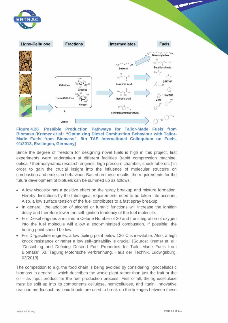
www.ertrac.org
Page 53 of 110
Figure 4.26 Possible Production Pathways for Tailor-Made Fuels from Biomass [Kremer et al.: “Optimizing Diesel Combustion Behaviour with Tailor-Made Fuels from Biomass”, 9th TAE International Colloquium on Fuels, 01/2013, Esslingen, Germany]
Since the degree of freedom for designing novel fuels is high in this project, first experiments were undertaken at different facilities (rapid compression machine, optical / thermodynamic research engines, high pressure chamber, shock tube etc.) in order to gain the crucial insight into the influence of molecular structure on combustion and emission behaviour. Based on these results, the requirements for the future development of biofuels can be summed up as follows:
• A low viscosity has a positive effect on the spray breakup and mixture formation. Hereby, limitations by the tribological requirements need to be taken into account. Also, a low surface tension of the fuel contributes to a fast spray breakup.
• In general: the addition of alcohol or furanic functions will increase the ignition delay and therefore lower the self-ignition tendency of the fuel molecule.
• For Diesel engines a minimum Cetane Number of 30 and the integration of oxygen into the fuel molecule will allow a soot-minimized combustion. If possible, the boiling point should be low.
• For DI-gasoline engines, a low boiling point below 120°C is inevitable. Also, a high knock resistance or rather a low self-ignitability is crucial. [Source: Kremer et. al.: “Describing and Defining Desired Fuel Properties for Tailor-Made Fuels from Biomass”, XI. Tagung Motorische Verbrennung, Haus der Technik, Ludwigsburg, 03/2013]
The competition to e.g. the food chain is being avoided by considering lignocellulosic biomass in general – which describes the whole plant rather than just the fruit or the oil – as input product for the fuel production process. First of all, the lignocellulose must be split up into its components cellulose, hemicellulose, and lignin. Innovative reaction media such as ionic liquids are used to break up the linkages between these
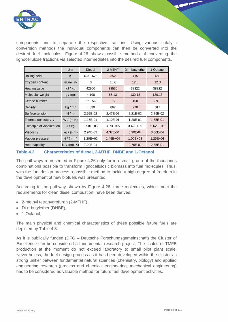
www.ertrac.org
Page 54 of 110
components and to separate the respective fractions. Using various catalytic conversion methods the individual components can then be converted into the desired fuel molecules. Figure 4.26 shows possible methods of converting the lignocellulose fractions via selected intermediates into the desired fuel components.
Table 4.3. Characteristics of diesel, 2-MTHF, DNBE and 1-Octanol
The pathways represented in Figure 4.26 only form a small group of the thousands combinations possible to transform lignocellulosic biomass into fuel molecules. Thus, with the fuel design process a possible method to tackle a high degree of freedom in the development of new biofuels was presented.
According to the pathway shown by Figure 4.26, three molecules, which meet the requirements for clean diesel combustion, have been derived:
• 2-methyl tetrahydrofuran (2-MTHF), • Di-n-butylether (DNBE), • 1-Octanol,
The main physical and chemical characteristics of these possible future fuels are depicted by Table 4.3.
As it is publically funded (DFG – Deutsche Forschungsgemeinschaft) the Cluster of Excellence can be considered a fundamental research project. The scales of TMFB production at the moment do not exceed laboratory to small pilot plant scale. Nevertheless, the fuel design process as it has been developed within the cluster as strong unifier between fundamental natural sciences (chemistry, biology) and applied engineering research (process and chemical engineering, mechanical engineering) has to be considered as valuable method for future fuel development activities.
Unit Diesel 2-MTHF Di-n-butylether 1-Octanol
Boiling point K 423 - 626 352 415 468
Oxygen content m./m. % 0 18.6 12.3 12.3
Heating value kJ / kg 42900 33530 38322 38322
Molecular weight g / mol ~ 198 86.13 130.13 130.13
Cetane number / 52 - 56 15 100 39.1
Density kg / m³ ~ 830 867 770 817
Surface tension N / m 2.69E-02 2.47E-02 2.21E-02 2.75E-02
Thermal conductivity W / (m K) 1.16E-01 1.10E-01 1.20E-01 1.65E-01
Enthalpie of vaporization J / kg 3.58E+05 3.89E+05 3.42E+05 5.62E+05
Viscosity kg / (s m) 2.94E-03 4.37E-04 6.90E-04 8.50E-04
Vapour pressure N / (m m) 1.20E+02 1.49E+04 1.00E+03 1.25E+01
Heat capacity kJ / (mol K) 7.20E-01 2.76E-01 2.85E-01
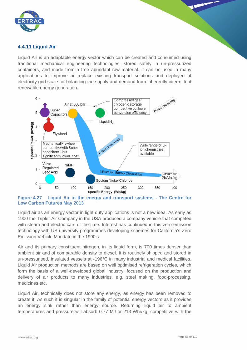
www.ertrac.org
Page 55 of 110
4.4.11 Liquid Air
Liquid Air is an adaptable energy vector which can be created and consumed using traditional mechanical engineering technologies, stored safely in un-pressurized containers, and made from a free abundant raw material. It can be used in many applications to improve or replace existing transport solutions and deployed at electricity grid scale for balancing the supply and demand from inherently intermittent renewable energy generation.
Figure 4.27 Liquid Air in the energy and transport systems - The Centre for Low Carbon Futures May 2013
Liquid air as an energy vector in light duty applications is not a new idea. As early as 1900 the Tripler Air Company in the USA produced a company vehicle that competed with steam and electric cars of the time. Interest has continued in this zero emission technology with US university programmes developing schemes for California’s Zero Emission Vehicle Mandate in the 1990’s.
Air and its primary constituent nitrogen, in its liquid form, is 700 times denser than ambient air and of comparable density to diesel. It is routinely shipped and stored in un-pressurised, insulated vessels at -196°C in many industrial and medical facilities. Liquid Air production methods are based on well optimised refrigeration cycles, which form the basis of a well-developed global industry, focused on the production and delivery of air products to many industries, e.g. steel making, food-processing, medicines etc.
Liquid Air, technically does not store any energy, as energy has been removed to create it. As such it is singular in the family of potential energy vectors as it provides an energy sink rather than energy source. Returning liquid air to ambient temperatures and pressure will absorb 0.77 MJ or 213 Whr/kg, competitive with the

www.ertrac.org
Page 56 of 110
best high energy density Li-ion batteries. The supply temperature of -169°C is a key enabler for harvesting low grade waste heat sources (around 100°C) such as combustion engine cooling systems.
Use of liquid air in propulsion systems has progressed from simple external heating to direct injection of the cryogenic liquid into a piston engine such as that developed by the Dearman Engine Company. Research work on split cycle concepts mixing both internal combustion and liquid air injection has also shown the potential for thermal efficiencies of around 60%.
Zero emission applications as a primary source is certainly of interest in urban scenarios for light duty, short range applications. For heavy duty applications, the energy density of Liquid Air is inappropriate for use as a primary fuel but it may provide opportunities for more efficient and cost effective waste heat recovery from internal combustion engines.
4.5 Renewable gaseous fuels
4.5.1 Bio / Algae Methane (CH4) via biogas
Biomethane is a methane-rich gas derived from biogas (generic term for gases produced by anaerobic fermentation or digestion of organic matter, main components are CH4 and CO2) or from gasification of biomass by upgrading to properties similar to those of Natural Gas (mainly CH4). A great benefit of biogas / biomethane when compared to other biofuels is that it can be produced from a great variety of sources as, basically, all types of bio matter can be used for this purpose (one of the most interesting options is the production from waste). Another important aspect for biomethane is that, being the same chemical composition as its fossil counterpart, there’s no blending limitation mandated by the engine performance.
As previously commented, its production is caused by the anaerobic digestion of organic matter (dead animal and plant material, manure, sewage sludge, organic waste, etc.), which is stored in air-tight tanks in order to reproduce the best possible conditions for the anaerobic microbes producing gas during the digestion process. It can also be produced by anaerobic degradation of organic matter in landfills, and then is referred to as landfill gas.
The raw gas derived from this process is known as biogas, and mainly consists of methane and CO2 plus some minor / trace components which greatly depend on the feedstock. Biomethane is known as the upgraded form of biogas, and its final quality/ composition is dependent on the operational parameters of the final use to be done of it, and on the upgrading technology used. See next Figure 4.28 for more details:
This basically means that biomethane, which is almost pure methane, is an ideal fuel for automotive applications. Depending on the source, several trace components have to be closely controlled when using biomethane as a vehicle fuel, such as siloxanes / silicon (risk of abrasion and increased probability for knocking and silica
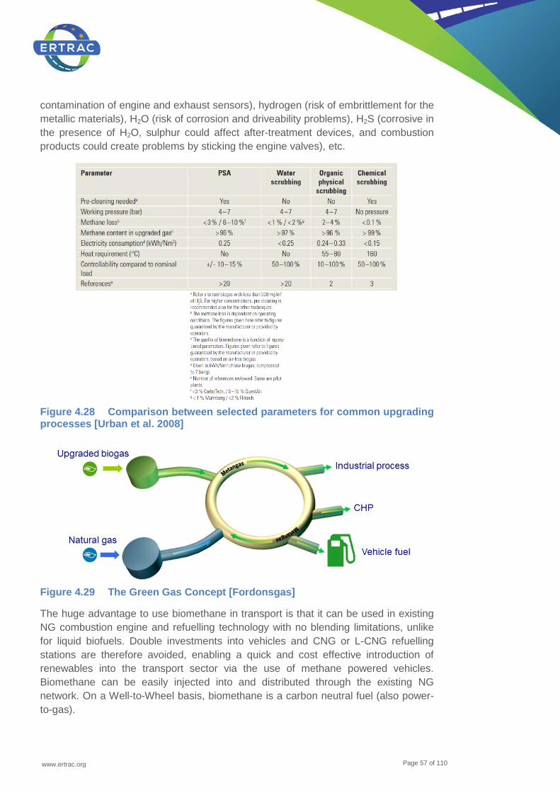
www.ertrac.org
Page 57 of 110
contamination of engine and exhaust sensors), hydrogen (risk of embrittlement for the metallic materials), H2O (risk of corrosion and driveability problems), H2S (corrosive in the presence of H2O, sulphur could affect after-treatment devices, and combustion products could create problems by sticking the engine valves), etc.
Figure 4.28 Comparison between selected parameters for common upgrading processes [Urban et al. 2008]
Figure 4.29 The Green Gas Concept [Fordonsgas]
The huge advantage to use biomethane in transport is that it can be used in existing NG combustion engine and refuelling technology with no blending limitations, unlike for liquid biofuels. Double investments into vehicles and CNG or L-CNG refuelling stations are therefore avoided, enabling a quick and cost effective introduction of renewables into the transport sector via the use of methane powered vehicles. Biomethane can be easily injected into and distributed through the existing NG network. On a Well-to-Wheel basis, biomethane is a carbon neutral fuel (also power-to-gas).
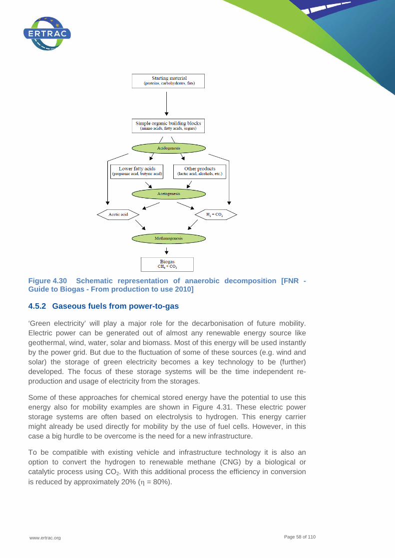
www.ertrac.org
Page 58 of 110
Figure 4.30 Schematic representation of anaerobic decomposition [FNR - Guide to Biogas - From production to use 2010]
4.5.2 Gaseous fuels from power-to-gas
‘Green electricity’ will play a major role for the decarbonisation of future mobility. Electric power can be generated out of almost any renewable energy source like geothermal, wind, water, solar and biomass. Most of this energy will be used instantly by the power grid. But due to the fluctuation of some of these sources (e.g. wind and solar) the storage of green electricity becomes a key technology to be (further) developed. The focus of these storage systems will be the time independent re-production and usage of electricity from the storages.
Some of these approaches for chemical stored energy have the potential to use this energy also for mobility examples are shown in Figure 4.31. These electric power storage systems are often based on electrolysis to hydrogen. This energy carrier might already be used directly for mobility by the use of fuel cells. However, in this case a big hurdle to be overcome is the need for a new infrastructure.
To be compatible with existing vehicle and infrastructure technology it is also an option to convert the hydrogen to renewable methane (CNG) by a biological or catalytic process using CO2. With this additional process the efficiency in conversion is reduced by approximately 20% (η = 80%).
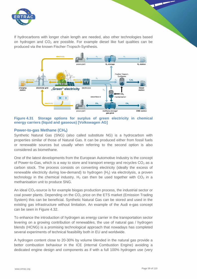
www.ertrac.org
Page 59 of 110
If hydrocarbons with longer chain length are needed, also other technologies based on hydrogen and CO2 are possible. For example diesel like fuel qualities can be produced via the known Fischer-Tropsch-Synthesis.
Figure 4.31 Storage options for surplus of green electricity in chemical energy carriers (liquid and gaseous) [Volkswagen AG]
Power-to-gas Methane (CH4) Synthetic Natural Gas (SNG) (also called substitute NG) is a hydrocarbon with properties similar of those of Natural Gas. It can be produced either from fossil fuels or renewable sources but usually when referring to the second option is also considered as biomethane.
One of the latest developments from the European Automotive Industry is the concept of Power-to-Gas, which is a way to store and transport energy and recycles CO2 as a carbon stock. The process consists on converting electricity (ideally the excess of renewable electricity during low-demand) to hydrogen (H2) via electrolysis, a proven technology in the chemical industry. H2 can then be used together with CO2 in a methanisation unit to produce SNG.
An ideal CO2-source is for example biogas production process, the industrial sector or coal power plants. Depending on the CO2 price on the ETS market (Emission Trading System) this can be beneficial. Synthetic Natural Gas can be stored and used in the existing gas infrastructure without limitation. An example of the Audi e-gas concept can be seen in Figure 4.32.
To enhance the introduction of hydrogen as energy carrier in the transportation sector levering on a growing contribution of renewables, the use of natural gas / hydrogen blends (HCNG) is a promising technological approach that nowadays has completed several experiments of technical feasibility both in EU and worldwide.
A hydrogen content close to 20-30% by volume blended in the natural gas provide a better combustion behaviour in the ICE (internal Combustion Engine) avoiding a dedicated engine design and components as if with a full 100% hydrogen use (very
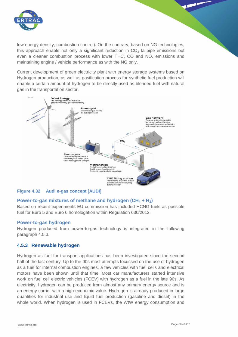
www.ertrac.org
Page 60 of 110
low energy density, combustion control). On the contrary, based on NG technologies, this approach enable not only a significant reduction in CO2 tailpipe emissions but even a cleaner combustion process with lower THC, CO and NOx emissions and maintaining engine / vehicle performance as with the NG only.
Current development of green electricity plant with energy storage systems based on Hydrogen production, as well as gasification process for synthetic fuel production will enable a certain amount of hydrogen to be directly used as blended fuel with natural gas in the transportation sector.
Figure 4.32 Audi e-gas concept [AUDI]
Power-to-gas mixtures of methane and hydrogen (CH4 + H2) Based on recent experiments EU commission has included HCNG fuels as possible fuel for Euro 5 and Euro 6 homologation within Regulation 630/2012.
Power-to-gas hydrogen Hydrogen produced from power-to-gas technology is integrated in the following paragraph 4.5.3.
4.5.3 Renewable hydrogen
Hydrogen as fuel for transport applications has been investigated since the second half of the last century. Up to the 90s most attempts focussed on the use of hydrogen as a fuel for internal combustion engines, a few vehicles with fuel cells and electrical motors have been shown until that time. Most car manufacturers started intensive work on fuel cell electric vehicles (FCEV) with hydrogen as a fuel in the late 90s. As electricity, hydrogen can be produced from almost any primary energy source and is an energy carrier with a high economic value. Hydrogen is already produced in large quantities for industrial use and liquid fuel production (gasoline and diesel) in the whole world. When hydrogen is used in FCEVs, the WtW energy consumption and

www.ertrac.org
Page 61 of 110
GHG emissions are significantly lower than these of vehicles with internal combustion engine. Traditional sources of H2 are natural gas, coal and refinery off-gases as well as electricity from the grid (by using the splitting of water by electrolysis). A reduction of GHG-emissions and energy consumption in comparison to internal combustion engines fuelled with gasoline or diesel can already be achieved when using hydrogen from natural gas reforming as fuel for FCEVs, due to their high energy conversion efficiency. However, only the production of hydrogen from renewable energy sources leads to almost zero GHG-emissions. Currently, hydrogen can already be produced by using renewable electricity (such as electricity from wind farms). The well-to-wheels energy consumption and GHG emissions using this pathway is significantly reduced with respect to ICEs fuelled with gasoline, diesel or CNG. Renewable energy sources such as solar power can produce renewable H2 from water electrolysis or emerging thermo-chemical water splitting technologies. Additionally, hydrogen can also be produced from biomass by a variety of processes, such as the gasification of biomass. The first process step of biomass gasification produces syngas, a mixture of mainly hydrogen and carbon monoxide, which can easily transformed into hydrogen with the water gas shift reaction. Another method is the production of hydrogen using by-products from the biodiesel production.
4.5.4 Solar to gas
Solar hydrogen from water thermochemical splitting is itself a totally renewable fuel and, if properly combined with CO (acquired from CO2 recycling), can produce clean energy fuels. Solar hydrogen can also be considered as a storage option of surplus green energy to chemical energy, substituting the hydrolysis step in relative installations.
Figure 4.33 The concept of carbon neutral solar fuel plant [CERT]
Recently, the HYDROSOL technology has been modified to produce carbon monoxide by carbon dioxide (CO2) splitting, under the same solar-aided two step concept described above. The two splitting processes can be combined and the produced carbon monoxide and hydrogen (solar synthesis gas) can be utilized for the production of synthetic fuels by established chemical processes, like the well-known
CO2
H2O
CH4, CxHyFuels & Chemicals
H2
Waste Heat for Solar Desalination H2O
Electric Energy
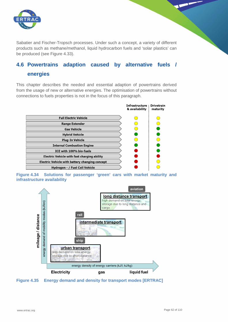
www.ertrac.org
Page 62 of 110
Sabatier and Fischer-Tropsch processes. Under such a concept, a variety of different products such as methane/methanol, liquid hydrocarbon fuels and ‘solar plastics’ can be produced (see Figure 4.33).
4.6 Powertrains adaption caused by alternative fuels / energies
This chapter describes the needed and essential adaption of powertrains derived from the usage of new or alternative energies. The optimisation of powertrains without connections to fuels properties is not in the focus of this paragraph.
Figure 4.34 Solutions for passenger ‘green’ cars with market maturity and infrastructure availability
Figure 4.35 Energy demand and density for transport modes [ERTRAC]
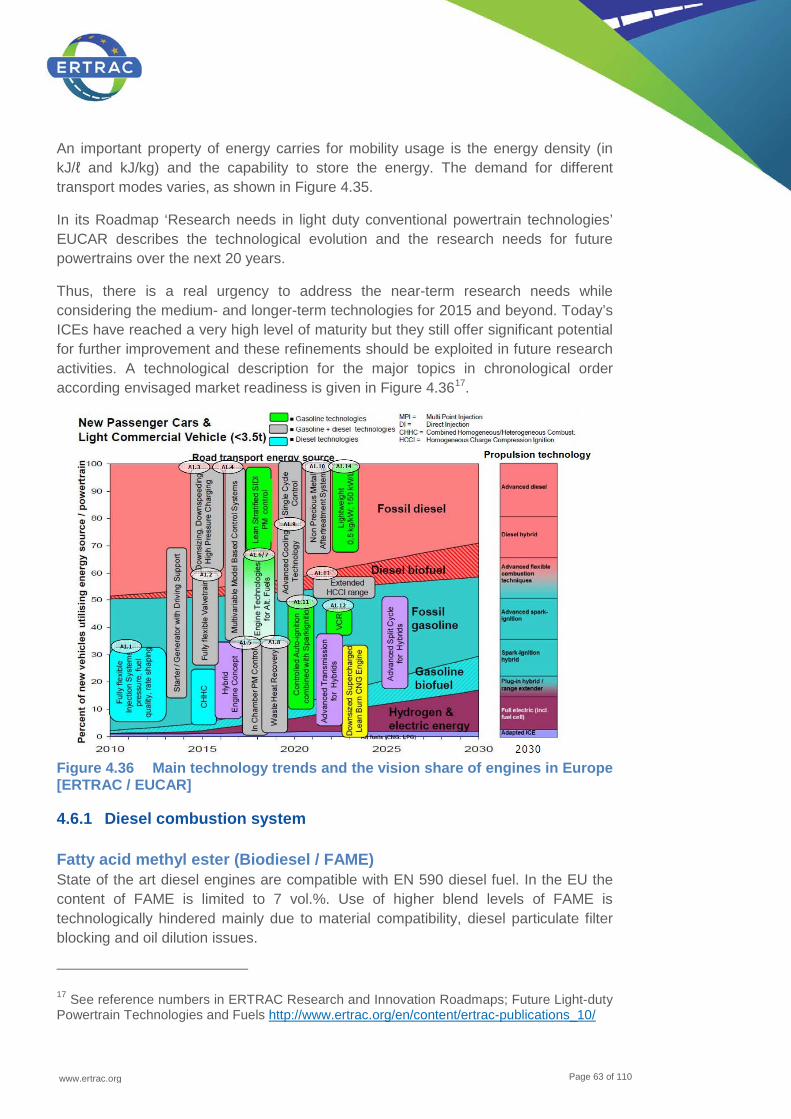
www.ertrac.org
Page 63 of 110
An important property of energy carries for mobility usage is the energy density (in kJ/ℓ and kJ/kg) and the capability to store the energy. The demand for different transport modes varies, as shown in Figure 4.35.
In its Roadmap ‘Research needs in light duty conventional powertrain technologies’ EUCAR describes the technological evolution and the research needs for future powertrains over the next 20 years.
Thus, there is a real urgency to address the near-term research needs while considering the medium- and longer-term technologies for 2015 and beyond. Today’s ICEs have reached a very high level of maturity but they still offer significant potential for further improvement and these refinements should be exploited in future research activities. A technological description for the major topics in chronological order according envisaged market readiness is given in Figure 4.3617.
Figure 4.36 Main technology trends and the vision share of engines in Europe [ERTRAC / EUCAR]
4.6.1 Diesel combustion system
Fatty acid methyl ester (Biodiesel / FAME) State of the art diesel engines are compatible with EN 590 diesel fuel. In the EU the content of FAME is limited to 7 vol.%. Use of higher blend levels of FAME is technologically hindered mainly due to material compatibility, diesel particulate filter blocking and oil dilution issues.
17 See reference numbers in ERTRAC Research and Innovation Roadmaps; Future Light-duty Powertrain Technologies and Fuels http://www.ertrac.org/en/content/ertrac-publications_10/

www.ertrac.org
Page 64 of 110
Advanced biogenous diesel components (HVO, BtL) The development of future liquid bio-fuels made from renewable resources as well as the significant further optimisation of currently existing bio-fuels (e.g. FAME, HVO) are also crucial steps on the road to sustainable mobility.
The development of process technologies for advanced diesel components e.g. synthetic diesel by ‘Fischer-Tropsch’ (FT) technology and ‘Hydrogenated vegetable oils’ (HVO, as well as hydrogenated animal fats) enables a wider panel of combustion approaches thanks to the specific fuel properties, mainly consisting in higher cetane number and low aromatics composition. Due to the good chemical and physical properties (in many cases mostly paraffinic) those fuels can be easily blended into conventional diesel. So called ‘blend walls’ are very high, e.g. some HVOs can be blended into diesel up to 30% without transgressing the diesel norm (EN 590). A good example is the currently running project ‘Diesel Regenerative’18. Advanced diesel component shall be compatible in very high blend amounts to the existing diesel technology to be called ‘drop-in fuels’ (definition see page 37).
Gasoline components in diesel combustion systems ED95 is a fuel consisting of ethanol (95 w/w%) and components to improve self-igniting properties and lubricity. The components make the ethanol fit to use in a compression ignited engine. An example on how this could work is the Scania ED95 engine (D95 ethanol fuel used in Scania engine consists of 95 w/w% hydrous ethanol (including denaturants) and 5 w/w% defined components).
Modifications have been made to an ordinary diesel engine:
• Compression ratios have been increased due to different ignition properties of the fuel (those engines aren’t downward compatible to EN 590 diesel)
• Fuel flow has been increased due to lower energy content of the fuel • Gasket, filters, sealing are exchanged to ethanol resistant materials
The engine is now the third generation ethanol engine at Scania. Some additional developments have been made in order to include ethanol in diesel fuel, such as emulsion pathways or specific blending strategies. These pathways have shown a great potential in terms of combustion optimisation, but still need development on a logistical point of view (fuel stability still not optimal, dedicating this type of fuels to captive fleets).
Combination of gasoline and diesel combustion Systems (HCCI / LTCS / GCI) ‘Homogeneous Charge Compression Ignition’ (HCCI), ‘Low Temperature Combustion Systems’ (LTCS) or ‘Gasoline Compressed Ignited’ (GCI) can be highlighted again in future regarding NOx emission if its issues are solved. HCCI can reduce NOx drastically due to its low combustion temperature and this can be attractive for ‘World
18 See http://www.hs-coburg.de/diesel_regenerativ.html

www.ertrac.org
Page 65 of 110
Light-duty Test Cycle’ (WLTC). Issues of the HCCI are: Realization in high load (difficult to control the auto ignition); Mode switching from/to the normal combustion (drivability during the mode switching).
Different projections suggest that in the coming decades, a) the worldwide demand for transport fuels will increase significantly, b) transport energy will still come substantially (around 90% share) from petroleum-based fuels and c) the demand increase will be significantly skewed towards commercial vehicles. On the current fuel/ engine technology trajectory, there will be a massive shift in demand towards diesel and jet fuels. Hence there is likely to be a surplus of lighter, less-processed fuels such as straight run gasoline from the initial distillation of crude.
Current diesel engines are efficient but expensive and complicated because they try to reduce NOx and soot simultaneously while using conventional diesel fuels which ignite very easily. Gasoline like fuels with high ignition delay make low-NOx/ low soot combustion very much easier – ‘Gasoline Compression Ignition’ (GCI) engines. Moreover, the RON of the optimum fuel for GCI engines is likely to be in the range of 70 - 85 and hence very much lower than that of current gasoline. Also, the fuel does not need to have high volatility to enable low soot/ low NOx combustion as long as the ignition delay is sufficiently large.
Thus the advantages of the GCI concept are:
• There is a potential for the engine to reach the same efficiency as current diesel engines and to be less complex for some parts (lower injection pressure, after-treatment focus on CO and HC rather than soot and NOx).
• The optimum fuel will be less processed and hence simpler to make compared to current gasoline or diesel fuels.
• It provides a path to mitigate the global demand imbalance between heavier and lighter fuels that is otherwise projected. The alternative is investment running into hundreds of millions of dollars globally in refineries to make the required diesel fuel even as the diesel engine continues to be expensive in order to meet stringent NOx/ soot requirements.
• On the other hand side the GCI combustion system implies new vehicles with new technology, because the very different fuel properties make the existing fleet not downwards compatible. This also causes a very high investment of hundreds of millions of dollars.
A lot of development work is needed before a GCI engine can power a practical vehicle. We should expect diesel engines to continue to run on diesel fuels in the near future since diesel manufacturers have such huge investments in and are able to meet all the requirements with current advanced, though expensive, technology. Also, the deployment of a new fuel/engine system such as GCI requires coordination between many stakeholders. This might be more feasible in markets where the commitment to existing technology is relatively weak or when the expected demand imbalance between diesel and gasoline begins to bite.

www.ertrac.org
Page 66 of 110
4.6.2 Gasoline combustion system
Alcohols: Butanol and Ethanol In the past the application of alternative fuels was mostly concentrated to special markets – e.g. for ethanol and ethanol blends in Brazil or Sweden. The increasing sensitivity towards dependency on crude oil significantly enhances the interest in alternative fuels. Besides of alcohol fuels made from food stock, bio-fuels of second generation from other sources are gaining interest. With spark ignited engines, different kinds of alcohols as well as gasoline/ alcohol blends still are the most promising alternative (liquid) fuels.
In Europe a remarkable technological trend has started during the last few years: Downsized TGDI (Turbocharged Gasoline Direct Injection) engines. The combination of gasoline direct injection and turbo charging leads to very attractive engine concepts yielding big improvements with regard to performance, fun-to-drive, emissions and fuel economy. This TGDI technology is expected to become the leading trend in passenger car population.
As ethanol is known to be a very attractive fuel for boosted engines, it does make sense to have a closer look into TGDI engine performance with ethanol as well as other alcohol fuels:
• The high octane number of alcohol fuels (especially ethanol) and the resulting excellent knock performance gives significant benefits, especially with highly boosted engines.
• The high heat of evaporation can be used to cool the charge for again knock suppression and increase of volumetric efficiency.
• The high oxygen content leads to reduced soot in the combustion process even under rich operating conditions.
• Small hardware changes are needed to use alcohol blends.
The same advantages described for Ethanol can be repeated for Butanol. Butanol is considered as a potential biofuel. Due to its lower oxygen contend the bend rate of butanol can be higher compared to ethanol and it contains more energy for a given volume than ethanol and almost as much as gasoline, so a vehicle using butanol would return fuel consumption more comparable to gasoline than ethanol. Butanol can also be used as a blended additive to diesel fuel to reduce soot emissions. Moreover, butanol is less hygroscopic in comparison with ethanol, which is remarkable advantage.
Use of a 10% ethanol blend results in a 25 - 30% reduction in carbon monoxide (CO) emissions by promoting a more complete combustion of the fuel. Use of ethanol can reduce net carbon dioxide (CO2) emissions by up to 100%, on a full life-cycle basis. Use of 10% ethanol-blended fuels results in a 6 - 10% reduction in net CO2. The carbon dioxide released from ethanol production activities and inputs, and its use, is less than that absorbed by the plants used to produce ethanol and the soil organic

www.ertrac.org
Page 67 of 110
matter. The carbon dioxide produced during ethanol production and gasoline combustion is extracted from the atmosphere by plants for starch and sugar formation during photosynthesis. It is assimilated by the crop in its roots, stalks and leaves, which usually return to the soil to maintain organic matter, or to the grain, the portion currently used to produce ethanol. Over time, the organic matter breaks down to carbon dioxide, but with the implementation of soil conservation measures, such as reduced tillage, the soil organic matter will build up. Therefore, by increasing its organic matter content, the soil acts as a significant sink for carbon dioxide.
There is little difference in the amount of emissions of nitrogen oxides from ethanol-blended fuels in relation to conventional fuels. Reports cite this difference in the range of a 5% decrease to a 5% increase for low-level ethanol blends. For ethanol blends in the range of 85 - 95%, the reduction in emissions of nitrogen oxides may be of the magnitude of 20%.
Agricultural grain production for ethanol may generate a slight increase in nitrous oxide (N2O) emissions resulting from heavy fertilizer use. However, research and advances in agricultural technology in grain production is resulting in a reduction of these emissions, often to levels below other common crops.
The net effect of ethanol use still results in an overall decrease in ozone formation, since the significant reduction in carbon monoxide emissions compensates for any slight increase in NOx.
Volatile organic compounds (VOCs) are highly reactive in the atmosphere, and are significant sources of ground-level ozone formation. Because ethanol oxygenates the fuel, there is approximately a 7% overall decrease in exhaust VOC's emitted from low-level ethanol-blended fuels in relation to conventional fossil fuels. In high level blends, the potential for exhaust VOC reduction is 30% or more.
Neither sulphur dioxide nor particulate matter emissions are considered of significance in gasoline-powered engines. Nevertheless, it is encouraging lower sulphur levels in gasoline, since sulphur can adversely affect the performance of emission-reducing catalytic converters. As ethanol contains no sulphur, and because it promotes more complete fuel combustion, blending gasoline with ethanol would reduce any potential for these emissions and the adverse effects of sulphur. In diesel engines, where SO2 and particulates are of concern, the use of ethanol-blended diesel or neat ethanol shows a significant reduction in these emissions.
Aldehydes have been associated with health risks. All oxygenates, including ethanol, emit higher levels of aldehydes than non-oxygenated gasoline. However, the risks associated with increased aldehyde emissions from ethanol-blended fuels are negligible, as the real quantity of emissions is quite small relative to other hazardous emissions, and are efficiently removed by the catalytic converter in a car.
R&D Challenges are:
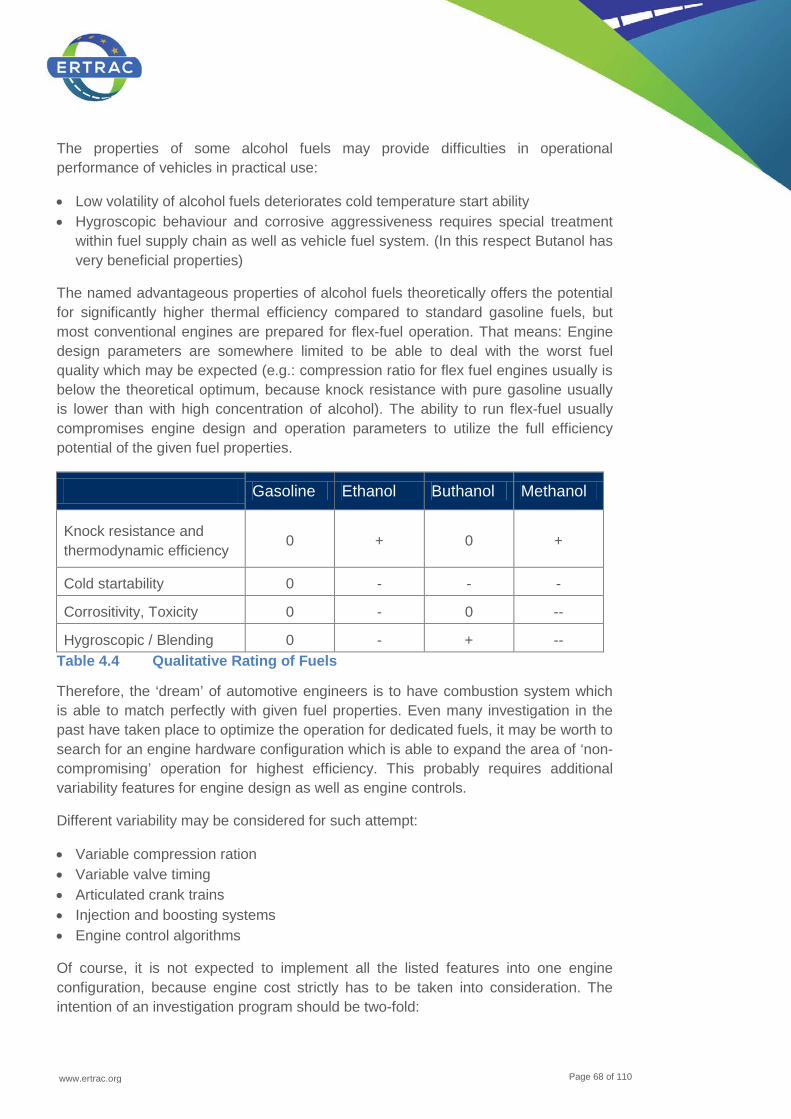
www.ertrac.org
Page 68 of 110
The properties of some alcohol fuels may provide difficulties in operational performance of vehicles in practical use:
• Low volatility of alcohol fuels deteriorates cold temperature start ability • Hygroscopic behaviour and corrosive aggressiveness requires special treatment
within fuel supply chain as well as vehicle fuel system. (In this respect Butanol has very beneficial properties)
The named advantageous properties of alcohol fuels theoretically offers the potential for significantly higher thermal efficiency compared to standard gasoline fuels, but most conventional engines are prepared for flex-fuel operation. That means: Engine design parameters are somewhere limited to be able to deal with the worst fuel quality which may be expected (e.g.: compression ratio for flex fuel engines usually is below the theoretical optimum, because knock resistance with pure gasoline usually is lower than with high concentration of alcohol). The ability to run flex-fuel usually compromises engine design and operation parameters to utilize the full efficiency potential of the given fuel properties.
Gasoline Ethanol Buthanol Methanol
Knock resistance and thermodynamic efficiency
0 + 0 +
Cold startability 0 - - -
Corrositivity, Toxicity 0 - 0 --
Hygroscopic / Blending 0 - + -- Table 4.4 Qualitative Rating of Fuels
Therefore, the ‘dream’ of automotive engineers is to have combustion system which is able to match perfectly with given fuel properties. Even many investigation in the past have taken place to optimize the operation for dedicated fuels, it may be worth to search for an engine hardware configuration which is able to expand the area of ‘non-compromising’ operation for highest efficiency. This probably requires additional variability features for engine design as well as engine controls.
Different variability may be considered for such attempt:
• Variable compression ration • Variable valve timing • Articulated crank trains • Injection and boosting systems • Engine control algorithms
Of course, it is not expected to implement all the listed features into one engine configuration, because engine cost strictly has to be taken into consideration. The intention of an investigation program should be two-fold:

www.ertrac.org
Page 69 of 110
• Identification of most promising fuel composition and blending range (preferably ethanol and/ or butanol)
• Identification of engine technology configuration, blend rate as well as control features which provide best cost/ benefit ratio
CNG and LNG Despite its long-time tradition, the potential of the ICE still remains significant due to its flexibility for both renewable and low-fossil-carbon fuels, high power density combined with long operation range and overall well-to-wheel efficiency in real-life operation.
The high power density achieved by the ICE downsizing reaches twofold effects. The smaller and lighter engine saves energy because it reduces vehicle weight and therefore also the corresponding vehicle driving resistances. Furthermore, under real-life conditions, the engine operates at higher specific torque levels and friction losses become relatively less important.
With NGVs (Natural Gas Vehicles), the limits of downsizing are not fully investigated and further investments into R&D are needed. Well-to-wheels efficiency and fossil CO2 emissions of Natural Gas ICE based powertrains are competitive in comparison to electric vehicles with an evident benefit in terms of operating range and vehicle price.
Fuel flexibility is of utmost importance in times of changing infrastructure for renewable fuels, including, e.g., shale NG, NG/ hydrogen blends. Adaptive ICEs shall bridge the time of developing infrastructures without requiring the customers to buy fuel-dedicated powertrains with limited operation range. Consequently, adaptive engine control for fuel flexibility has to be developed using advanced control strategies, sensors and actuators. They require intensive Hardware-in-the-Loop and Software-in-the-Loop R&D, including the integration of control to higher (traffic network management) systems. Low carbon fuels with uncompromised operation range make the ICE very competitive at global markets.
The low production cost, the proven durability and operation reliability of Natural Gas ICE powertrains are very reasonable and offer further design improvement potential.
In conclusion, Natural Gas ICE powertrains development continues to offer the steady progress towards sustainable mobility with limited risk and based on long proven technology while searching for innovative concepts and breakthroughs in emerging technologies.
That is why the provident R&D support should balance all possible ways to the future mobility devices. The main expectations coming from the Natural Gas exploitation in transportation sector are:
• Primary energy savings (aiming at energy security) • Cut of GHG emissions (preventing climate change)
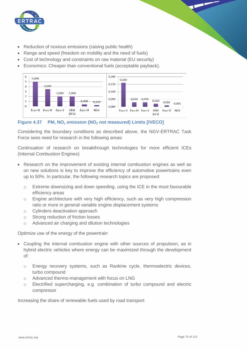
www.ertrac.org
Page 70 of 110
• Reduction of noxious emissions (raising public health) • Range and speed (freedom on mobility and the need of fuels) • Cost of technology and constraints on raw material (EU security) • Economics: Cheaper than conventional fuels (acceptable payback).
Figure 4.37 PM, NOx emission (NO2 not measured) Limits [IVECO]
Considering the boundary conditions as described above, the NGV-ERTRAC Task Force sees need for research in the following areas:
Continuation of research on breakthrough technologies for more efficient ICEs (Internal Combustion Engines)
• Research on the improvement of existing internal combustion engines as well as on new solutions is key to improve the efficiency of automotive powertrains even up to 50%. In particular, the following research topics are proposed:
o Extreme downsizing and down speeding, using the ICE in the most favourable efficiency areas
o Engine architecture with very high efficiency, such as very high compression ratio or more in general variable engine displacement systems
o Cylinders deactivation approach o Strong reduction of friction losses o Advanced air charging and dilution technologies
Optimize use of the energy of the powertrain
• Coupling the internal combustion engine with other sources of propulsion, as in hybrid electric vehicles where energy can be maximized through the development of:
o Energy recovery systems, such as Rankine cycle, thermoelectric devices, turbo compound
o Advanced thermo-management with focus on LNG o Electrified supercharging, e.g. combination of turbo compound and electric
compressor
Increasing the share of renewable fuels used by road transport
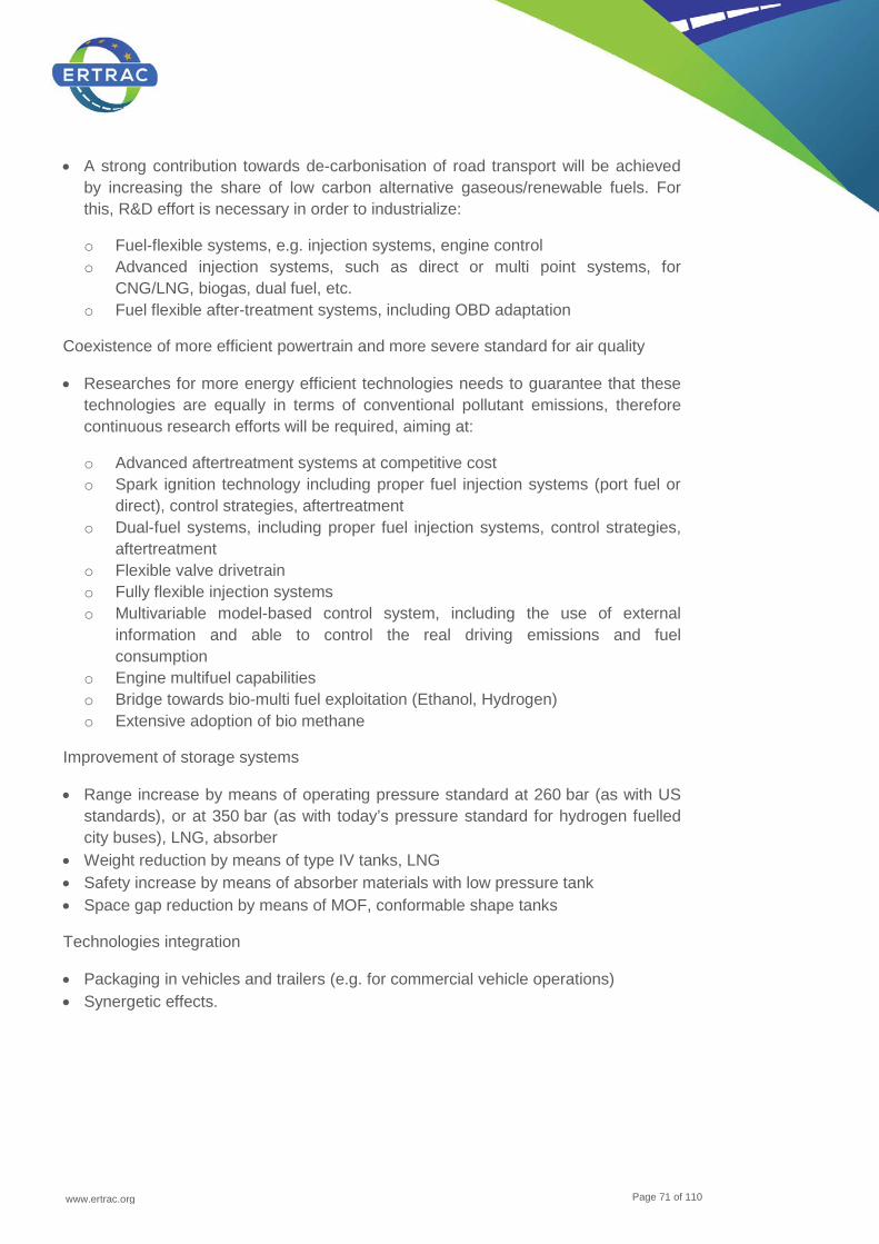
www.ertrac.org
Page 71 of 110
• A strong contribution towards de-carbonisation of road transport will be achieved by increasing the share of low carbon alternative gaseous/renewable fuels. For this, R&D effort is necessary in order to industrialize:
o Fuel-flexible systems, e.g. injection systems, engine control o Advanced injection systems, such as direct or multi point systems, for
CNG/LNG, biogas, dual fuel, etc. o Fuel flexible after-treatment systems, including OBD adaptation
Coexistence of more efficient powertrain and more severe standard for air quality
• Researches for more energy efficient technologies needs to guarantee that these technologies are equally in terms of conventional pollutant emissions, therefore continuous research efforts will be required, aiming at:
o Advanced aftertreatment systems at competitive cost o Spark ignition technology including proper fuel injection systems (port fuel or
direct), control strategies, aftertreatment o Dual-fuel systems, including proper fuel injection systems, control strategies,
aftertreatment o Flexible valve drivetrain o Fully flexible injection systems o Multivariable model-based control system, including the use of external
information and able to control the real driving emissions and fuel consumption
o Engine multifuel capabilities o Bridge towards bio-multi fuel exploitation (Ethanol, Hydrogen) o Extensive adoption of bio methane
Improvement of storage systems
• Range increase by means of operating pressure standard at 260 bar (as with US standards), or at 350 bar (as with today’s pressure standard for hydrogen fuelled city buses), LNG, absorber
• Weight reduction by means of type IV tanks, LNG • Safety increase by means of absorber materials with low pressure tank • Space gap reduction by means of MOF, conformable shape tanks
Technologies integration
• Packaging in vehicles and trailers (e.g. for commercial vehicle operations) • Synergetic effects.
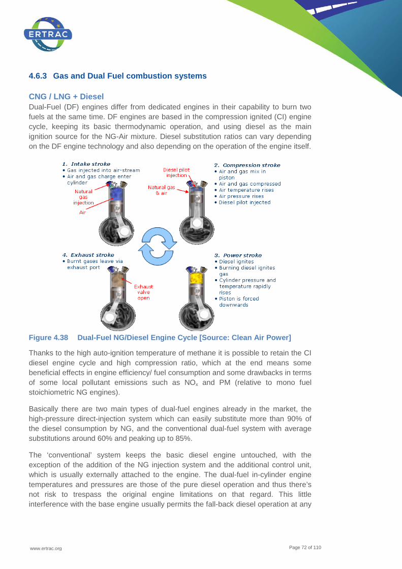
www.ertrac.org
Page 72 of 110
4.6.3 Gas and Dual Fuel combustion systems
CNG / LNG + Diesel Dual-Fuel (DF) engines differ from dedicated engines in their capability to burn two fuels at the same time. DF engines are based in the compression ignited (CI) engine cycle, keeping its basic thermodynamic operation, and using diesel as the main ignition source for the NG-Air mixture. Diesel substitution ratios can vary depending on the DF engine technology and also depending on the operation of the engine itself.
Figure 4.38 Dual-Fuel NG/Diesel Engine Cycle [Source: Clean Air Power]
Thanks to the high auto-ignition temperature of methane it is possible to retain the CI diesel engine cycle and high compression ratio, which at the end means some beneficial effects in engine efficiency/ fuel consumption and some drawbacks in terms of some local pollutant emissions such as NOx and PM (relative to mono fuel stoichiometric NG engines).
Basically there are two main types of dual-fuel engines already in the market, the high-pressure direct-injection system which can easily substitute more than 90% of the diesel consumption by NG, and the conventional dual-fuel system with average substitutions around 60% and peaking up to 85%.
The ‘conventional’ system keeps the basic diesel engine untouched, with the exception of the addition of the NG injection system and the additional control unit, which is usually externally attached to the engine. The dual-fuel in-cylinder engine temperatures and pressures are those of the pure diesel operation and thus there’s not risk to trespass the original engine limitations on that regard. This little interference with the base engine usually permits the fall-back diesel operation at any

www.ertrac.org
Page 73 of 110
moment, offering the vehicle owner the possibility to run completely on diesel if there’s any problem of NG supply i.e.
In these conventional DF systems, the injection signals are generally based on manifold pressure, charge air temperature, gas pressure, gas temperature, and fuel mapping, providing the best combination of emissions and efficiency.
These engines can run with either Compressed Natural Gas or Liquefied Natural Gas and this difference will basically fall under the final customer decision, as it is just a matter of required vehicle range through the energy density accumulated in the NG storage system.
The second type of DF technology already in the market but not so widespread yet is the High-Pressure Direct-Injection (HPDI).
HPDI technology uses natural gas as the primary fuel along with a small amount of diesel as a pilot ignition source, or ‘liquid spark plug’.
At the heart of the engine is a new injector with a dual-concentric needle design. It allows for small quantities of diesel fuel and large quantities of natural gas to be delivered at high pressure to the combustion chamber. The natural gas is injected at the end of the compression stroke. Under the pressures found in the combustion chamber of a normal diesel engine, natural gas requires a higher ignition temperature than diesel. To assist with ignition, a small amount of diesel fuel is injected into the engine cylinder followed by the main natural gas fuel injection. The diesel acts as a pilot, rapidly igniting the hot combustion products, and thus the natural gas. HPDI replaces approximately 95% of the diesel fuel (by energy) with natural gas.
HPDI injectors are designed to be incorporated into these engines with minimal or no modifications to the cylinder head. No special pistons, cams, gas mixer or port injectors are needed.
Late-cycle, high-pressure direct injection ensures diffusion type combustion and therefore retains the high power, torque, and efficiency of a diesel engine.
The benefits of the Natural Gas Vehicles adoption in Europe can be summarised as follows:
• Capability to provide a relevant contribution for 2020 CO2 abatement targets
o Allowing drastic reductions of greenhouse gases (especially through the use of biomethane or NG/ hydrogen mixtures and synthetic methane using from a surplus of renewable electricity via the Power-to-Gas technology) and local pollution as photochemical smog (ozone)
• Real alternative to conventional liquid fuelled vehicles (both from fossil and renewable sources)

www.ertrac.org
Page 74 of 110
o Strategic in terms of energy security due to independence to crude oil and replacement with geopolitically well distributed sources and higher ratio consumption / reserves than conventional fuels
• Compliance towards 2020+ targets with massive adoption of bio methane
o Immediate usage of bio methane w/o change in technology and a bridge for bio-multi fuel exploitation (Ethanol, Hydrogen)
• The already most relevant fleet of alternative fuel vehicles in Europe (close to 1 Million units)
o It’s a mature technology that have already demonstrated a relevant contribution to lower gaseous and acoustical emissions than conventional fuels
• Flexibility to adopt all technologies under development for conventional fuel enhancing the benefits thanks to a synergic integration
o Capability to improve engine efficiency above 50% adopting new technologies under development for conventional fuel engines
o Capability to sustain market demand during economic crisis and/or price peaks for the barrel of oil, cheaper than conventional fuels with acceptable payback
• Pipelines network well diffused and ready to host bio methane injection
o In some European countries there is an adequate availability of refuelling stations (some 3,300 stations all over the European Union), and vehicle portfolio with conventional fuel equivalent range and engine performance.
The main challenges for DF engines are:
• Minimize CO2 emission by maximizing engine efficiency and blend ratio ‘CNG and diesel’. This also leads to minimal operating (fuel) costs;
• Control tailpipe methane and NMHC emissions to levels set by emission legislation. This is a research topic for monofuel as well as dual fuel concepts;
• Flexibility to usage of different fuels, like bio methane, DME, methanol.
To meet emission targets, especially for HC emissions, steps are required in aftertreatment technology and engine control. Engine out HC emissions can be reduced by hardware optimization in combination with advanced fuelling strategies. Enhanced low temperature methane emission reduction requires improved catalyst technology and thermal management.
CNG + Hydrogen (H2) To enhance the introduction of hydrogen as energy carrier in the transportation sector levering on a growing contribution of renewables, the use of natural gas / hydrogen
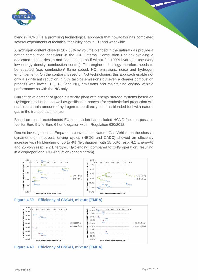
www.ertrac.org
Page 75 of 110
blends (HCNG) is a promising technological approach that nowadays has completed several experiments of technical feasibility both in EU and worldwide.
A hydrogen content close to 20 - 30% by volume blended in the natural gas provide a better combustion behaviour in the ICE (internal Combustion Engine) avoiding a dedicated engine design and components as if with a full 100% hydrogen use (very low energy density, combustion control). The engine technology therefore needs to be adapted (e.g. combustion/ flame speed, NOx emissions, noise and hydrogen embrittlement). On the contrary, based on NG technologies, this approach enable not only a significant reduction in CO2 tailpipe emissions but even a cleaner combustion process with lower THC, CO and NOx emissions and maintaining engine/ vehicle performance as with the NG only.
Current development of green electricity plant with energy storage systems based on Hydrogen production, as well as gasification process for synthetic fuel production will enable a certain amount of hydrogen to be directly used as blended fuel with natural gas in the transportation sector.
Based on recent experiments EU commission has included HCNG fuels as possible fuel for Euro 5 and Euro 6 homologation within Regulation 630/2012.
Recent investigations at Empa on a conventional Natural Gas Vehicle on the chassis dynamometer in several driving cycles (NEDC and CADC) showed an efficiency increase with H2 blending of up to 4% (left diagram with 15 vol% resp. 4.1 Energy-% and 25 vol% resp. 9.2 Energy-% H2-blending) compared to CNG operation, resulting in a disproportional CO2-reduction (right diagram).
Figure 4.39 Efficiency of CNG/H2 mixture [EMPA]
Figure 4.40 Efficiency of CNG/H2 mixture [EMPA]

www.ertrac.org
Page 76 of 110
These measurements were performed without any modifications on the vehicle (test series: “…/org”) as well as with lightly modified ignition map (test series: “…/mod”) in the operational range of the NEDC. Without ECU modification, the NOx emissions in the NEDC were reduced with hydrogen blending of 9.2 energy-percent by 20 - 30% and the T.HC emissions by 10 to 40%. With a simple ignition retard of 1-3 °CA, the NOx-reduction could be increased to 50 – 70% and the T.HC reduction to 30 - 80%.
These investigations show, that the H2 blending to CNG is improving the ignition phase significantly, which is improving both the efficiency and the emissions behaviour. However, more research is needed for understanding the underlying processes, the catalyst and oil aging or the operational behaviour in real operation as well as the resulting knocking resistance of the fuel and the engine control system capability to match base fuel (CNG) composition and hydrogen concentration.
Partially premixed combustion with two fuels Generally the main idea of advanced combustion systems is based on ‘low temperature combustion’ (LTC), using very lean homogeneous mixture. The advantages consist in high ratio of constant pressure/constant volume thermal capacities, which enhances thermal efficiency due to low temperature (up to 1500 – 1700 K, still sufficient for good Carnot efficiency of approx. 80%) and low tri-atomic gas contents and reduces cooling losses. Moreover, the knock occurrence is supressed and additional increase of compression ratio is possible. NOx formation is reduced together with soot unlike the standard trade-off behaviour of diffusion flame. The disadvantages may consist in problems with stable ignition (both spark and compression ignition), slow flame speed and high amount of unburned organic species due to flame quenching.
Therefore, the pure principle has to be modified for practical use. The huge amount of modifications exists, using flame acceleration by moderate knock in the whole lean mixture volume (homogeneous charge compression ignition, HCCI) supported by increased temperature due to internal or external uncooled exhaust gas recirculation (IGR or EGR), which needs often variable valve timing or actuation (VVT, VVA) for negative valve overlap. Those measures act obviously against the basic idea (low temperature and low contents of burnt gases). In practice, some compromise has to be found for stable HCCI. Spark assistance of compression ignition (SACI) may stabilize ignition of highly compressed lean mixture, while the initial deflagration flame is changed to knock of a suitable part of rest mixture.
Local concentration inhomogeneity acts in the same way, whereas flexibility of injection splitting in todays’ common-rail fuel injection systems is applied. The early injection forms almost homogeneous mixture, which is chemically transformed and prepared for compression ignition during compression stroke. The other injected sprays act as igniters and rest of injected fuel may be burnt in diffusion flame without too intensive soot and NOx formation (premixed charge compression ignition, PCCI, partially premixed charge PPC, etc.). The originally lean mixture may be formed outside of a cylinder by injecting of liquid fuel or delivering gaseous fuel to, e.g., inlet
www.ertrac.org
Page 77 of 110
port again, compromise solution has to be found. Ignition issue and small flame velocity are solved by replacing small number of rich mixture occurrence to reduce soot formation inside diffusion flame core and to avoid knock despite using high compression ratio.
PCCI makes a bridge to dual fuel LTC engines with reaction controlled combustion (RCCI, etc.), while more reactive fuel of high cetane number is injected into a cylinder just before combustion start but the basic lean mixture of 40 – 70% of the total energy supply is prepared with significantly advance during inlet process or at the start of compression. The second fuel may be stored in vehicle tanks, produced in an on-board reformer or created during combustion in dedicated cylinders of the engine. The results published and summarized by R. Reitz, ERC University of Wisconsin-Madison, are enclosed in the following pictures. The experiments were done using gasoline/ diesel or E85/ diesel and fuel blends. RCCI is well controllable.
The RCCI and dual-fuel operation of a vehicle powertrain is promising in the case of combination of lean NG mixture and diesel oil or other high-cetane fuel (e.g. HVO, DME) used as the secondary fuel supply. The slow methane combustion may be accelerated by multiple ignitions from sprays of high cetane number fuel and the afterburning may be terminated by knock onset. Low carbon gaseous fuels (including addition of hydrogen) may be used as basic lean mixture sources. The specific power of those engines has to be supported by turbo/supercharging with appropriate EGR. The stable ignition at any load/speed and during transients calls for highly flexible control (VVT, VVA combined with boost control and/ or externally driven supercharger). The exhaust gas aftertreatment system should be able to transform unburned organic species even at low temperature, since HC (especially methane) and CO emissions can be high. NOx and soot do not seem to create a major problem. Despite these engine lay-out complications, dual-fuel RCCI engines may solve both efficiency and pollution issues for the future, especially if cheap shale gas is available.
DME Currently, virtually all heavy duty trucks are powered with diesel engines. The heavy duty truck with a diesel engine is a concept that has been developed and continuously improved for a long time to provide a combination of features (power, reliability, range, etc.) that enables a high productivity for a transport provider. The engine features together with the high energy density and the simple and efficient transport and storage of the diesel fuel makes it a challenge to compete with for any alternative propulsion system.
DME has been identified as a promising alternative, where the disadvantages compared to diesel are acceptable, and even with some advantages. A DME installation on a HD vehicle has very good synergies with existing diesel engine installation in platforms; by changing a limited amount of components it’s possible to develop a DME variant of a diesel vehicle. This possibility reduces the complexity of the system which is very important to bring down the cost. Because of volume effects,
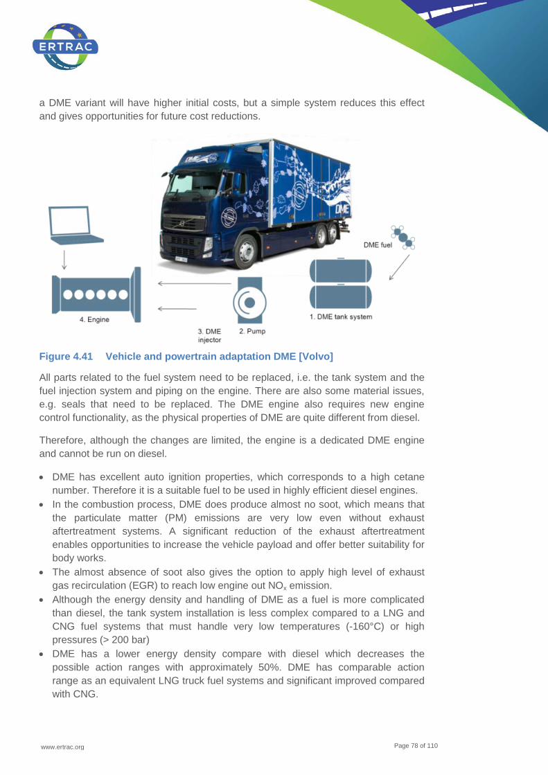
www.ertrac.org
Page 78 of 110
a DME variant will have higher initial costs, but a simple system reduces this effect and gives opportunities for future cost reductions.
Figure 4.41 Vehicle and powertrain adaptation DME [Volvo]
All parts related to the fuel system need to be replaced, i.e. the tank system and the fuel injection system and piping on the engine. There are also some material issues, e.g. seals that need to be replaced. The DME engine also requires new engine control functionality, as the physical properties of DME are quite different from diesel.
Therefore, although the changes are limited, the engine is a dedicated DME engine and cannot be run on diesel.
• DME has excellent auto ignition properties, which corresponds to a high cetane number. Therefore it is a suitable fuel to be used in highly efficient diesel engines.
• In the combustion process, DME does produce almost no soot, which means that the particulate matter (PM) emissions are very low even without exhaust aftertreatment systems. A significant reduction of the exhaust aftertreatment enables opportunities to increase the vehicle payload and offer better suitability for body works.
• The almost absence of soot also gives the option to apply high level of exhaust gas recirculation (EGR) to reach low engine out NOx emission.
• Although the energy density and handling of DME as a fuel is more complicated than diesel, the tank system installation is less complex compared to a LNG and CNG fuel systems that must handle very low temperatures (-160°C) or high pressures (> 200 bar)
• DME has a lower energy density compare with diesel which decreases the possible action ranges with approximately 50%. DME has comparable action range as an equivalent LNG truck fuel systems and significant improved compared with CNG.
www.ertrac.org
Page 79 of 110
• DME fuel is basically composed of only one single molecule. This reduces the risk for any local market issues related to different fuel qualities, Diesel as a comparison is a mixture of thousands of different hydrocarbons and the quality varies over the world, also natural gas quality can be very different in different markets. Nevertheless, a fuel specification is necessary to control impurities and secure the addition of lubricity additives.
• DME has poor lubricity, and therefore a lubricity improver is needed to be added to the fuel.
• DME is non-toxic with rapid degradation to CO2 in air. There are no known environmental impacts.
• The physical properties of DME make it more difficult to reach very high injection pressures.
• The e.g. Volvo BioDME vehicles meet Euro V emission levels by use of EGR and oxidation catalyst.
4.6.4 Fuel cell vehicles (FCEV)
Fuel Cell Electric Vehicles are vehicles which are propelled by an electric motor which receives the electricity from a fuel cell system. In the fuel cell system, the chemical energy of a fuel is converted in electricity in an electrochemical process. The driving range of FCEVs is comparable to the range of vehicles with internal combustion engine; the filling time is also similar. FCEVs have been developed intensively by many car manufacturers since the early nineties of the last century and will be available on the market in the next years. Currently, some hundreds of FCEVs are operated worldwide, mainly in demonstration projects. Like battery electric vehicles, they offer a significant reduction of green-house-gas emissions and energy consumption, especially when the fuel is produced from renewable energy sources (e.g. wind energy, photovoltaic, and biomass). Today, only hydrogen is used as a fuel for FCEVs, it is usually stored as compressed gas in 700 bar pressure tanks. The most active regions in the world are Europe (mainly Germany, Scandinavia, United Kingdom and Spain), the United States, Japan and Korea. In these regions, the governments provide significant budgets for research and development, demonstration projects and infrastructure build up. To overcome the chicken-and-egg problem FCEV/ hydrogen infrastructure, in all these regions, initiatives have been found to initiate the build-up of a hydrogen infrastructure. In these initiatives, car industry, gas industry, oil industry, electricity providers and the governments join forces to carry the initial financial burden for the build-up of the needed hydrogen infrastructure with the clear goal to achieve a positive business case in a later stage. Besides the hurdle of the almost not yet existing hydrogen refuelling stations, cost of the FCEV is the other main barrier for market success. Thus, the car industry is working on measures to reduce the cost of FCEV technology significantly by a factor of more than 10 compared to the status in 2010 until 2020. This can only be achieved by the combination of technological development, build-up of a supplier network and scale effects through higher production numbers. Just recently, some of the car manufacturers have joined forces by agreeing upon cooperation (e.g. the Daimler-

www.ertrac.org
Page 80 of 110
Ford-Nissan cooperation and the BMW-Toyota cooperation) to achieve the goal of a market introduction between 2015 and 2020 (depending on the individual company goals).
4.6.5 Battery electric vehicles (BEV)
Due to the goal of this roadmap the potential of the usage of electricity is not described in this roadmap. Details on the usage of electricity in vehicles, like battery electric vehicles, are given in the joint ERTRAC, EPoSS, Smartgrids roadmap ‘Electrification Roadmap version - 2nd Edition’19.
4.6.6 Hybrid demands
The electrification of vehicle drive trains is an important step to increase energy security, improvement of air quality and CO2 reduction. ERTRAC published a roadmap on hybridisation ‘Hybridisation of Road Transport’19. Future customer demands combined with legal requirements will drive the introduction of ‘Hybrid Electric Vehicle’ (HEV) technologies, increasing the energy efficiency of vehicles propelled by conventional power-trains which solely utilise fossil fuels, while developing enabling technologies for the future large scale vehicle electrification. Without brought hybridisation, especially with Plug-In Hybrids, the goals of decarbonisation could not be achieved.
Figure 4.42 The classification of Hybrids [ERTRAC]
As a first step to electrification start-stop and starter-generator systems are already in a market penetration phase, pure Electric Vehicles (EV) is announced for the next years. A real series market penetration is seen after 2020. Currently starter/ generator systems are not a part of propulsion. However, recent discussions indicate that 5 to 10 kW starters could be used for driving support.
19 See http://www.ertrac.org/en/content/ertrac-publications_10/

www.ertrac.org
Page 81 of 110
With the help of hybrid system, ICE can optimize its running conditions. This leads to the idea to optimize intake/ compression stroke and combustion/ expansion stroke by splitting them. Thus we would expect in future such advanced split cycles for hybrids.
An essential question for the moment is however, if hybrid configurations are to be seen as a suitable transition-form, as the bridge technology to pure Electric Vehicles, or if e.g. Plug-In Hybrid, Range Extender Hybrid and other new hybrid solutions are the meaningful alternative to pure Electric Vehicles at the end. The advantage of these hybrid configurations lays in the stepwise transition to electrification without giving away customer benefits.
We expect that hybrids will play a role for long time, more than today expected. Hybrids are one solution to reduce CO2 and thus the answer for future CO2 legislation. This demand of the future regarding sustainable mobility will show us as most build hybrid configurations the ‘Plug-In Hybrids’ as best utility for ‘All-round’ cars and the ‘Range Extender Hybrid’ as a solution for conurbation. For more details see ERTRAC roadmap on ‘Hybridisation of Road Transport’. Heavy Duty truck hybrids for use on Electric Road Systems (ERS) also hold potential to increase the use of renewable electricity. For details see ERTRAC roadmap on “Heavy Duty Trucks” Special demands coming from hybridisation are:
• Energy Storage Systems • Drive Train Technologies (e.g. more robust ICEs due to less operation time) • New fuel quality demands (e.g. due to the longer resistance in the vehicle tank) • System Integration & Modular Hybrid Architecture • Grid Integration • Safety aspects • Integration into the Transport System • Combination of ICE control with ICT: GPS can help to optimize braking
recuperation of the Hybrid system and some ideas have been developed; for example, start regenerative braking gently before entering e.g. zone 30.
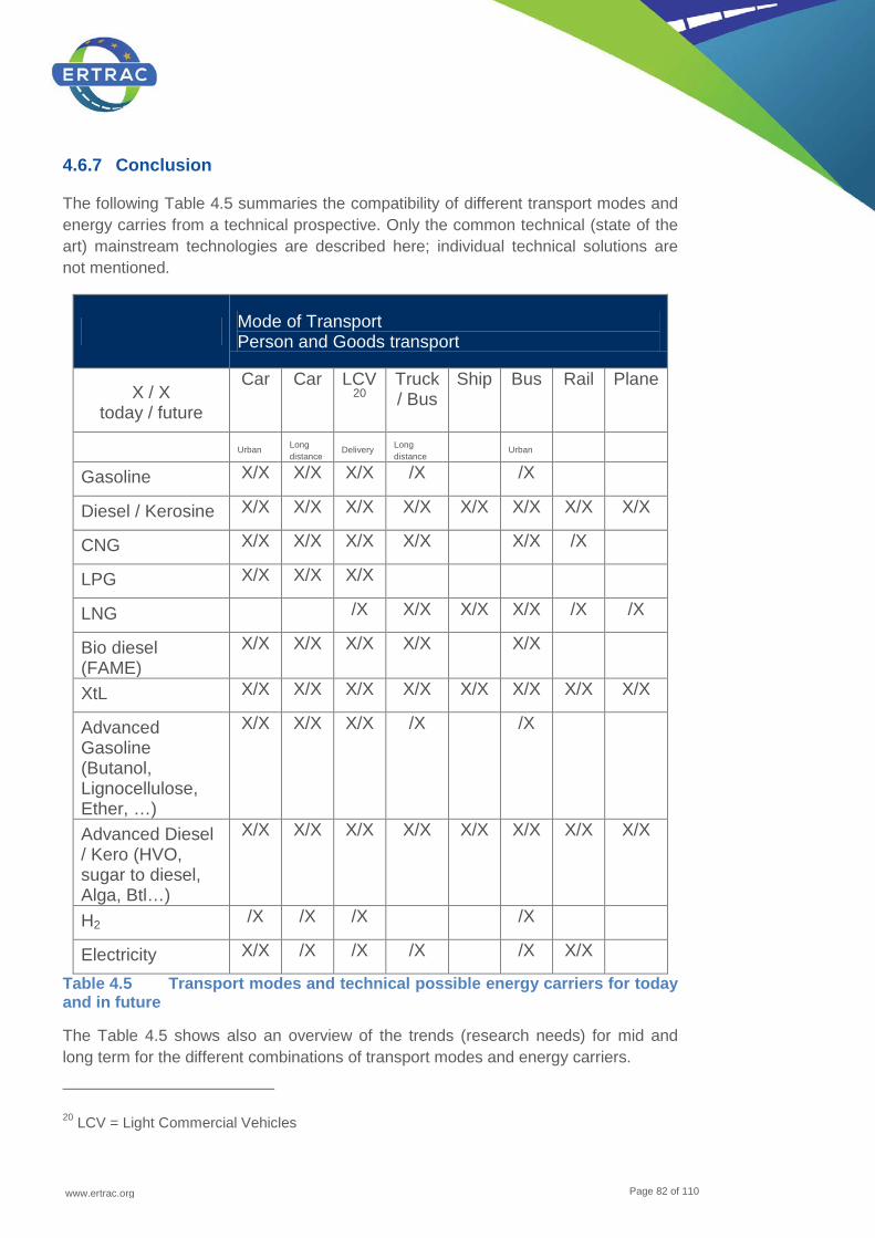
www.ertrac.org
Page 82 of 110
4.6.7 Conclusion
The following Table 4.5 summaries the compatibility of different transport modes and energy carries from a technical prospective. Only the common technical (state of the art) mainstream technologies are described here; individual technical solutions are not mentioned.
Mode of Transport Person and Goods transport
X / X today / future
Car Car LCV20
Truck/ Bus
Ship Bus Rail Plane
Urban Long distance
Delivery Long distance
Urban
Gasoline X/X X/X X/X /X /X
Diesel / Kerosine X/X X/X X/X X/X X/X X/X X/X X/X
CNG X/X X/X X/X X/X X/X /X
LPG X/X X/X X/X
LNG /X X/X X/X X/X /X /X
Bio diesel (FAME)
X/X X/X X/X X/X X/X
XtL X/X X/X X/X X/X X/X X/X X/X X/X
Advanced Gasoline (Butanol, Lignocellulose, Ether, …)
X/X X/X X/X /X /X
Advanced Diesel / Kero (HVO, sugar to diesel, Alga, Btl…)
X/X X/X X/X X/X X/X X/X X/X X/X
H2 /X /X /X /X
Electricity X/X /X /X /X /X X/X
Table 4.5 Transport modes and technical possible energy carriers for today and in future
The Table 4.5 shows also an overview of the trends (research needs) for mid and long term for the different combinations of transport modes and energy carriers.
20 LCV = Light Commercial Vehicles

www.ertrac.org
Page 83 of 110
4.7 Future infrastructure
4.7.1 Infrastructure for diesel and gasoline fuels
Today’s fuel supply and distribution systems have been adapted to the properties of conventional bio-blend stocks. For example, ethanol, because of its affinity for water, is typically added to gasoline at blending terminals and transported to service stations by truck in order to minimise water separation and corrosion. Similarly, conventional biodiesel components (FAME) can increase the potential for materials incompatibilities and contamination in manufacturing and distribution. Fuel supply and distribution systems have been successfully engineered to minimise these problems over a range of environmental and climatic conditions. Major new research is not needed because most problems can be resolved through proper materials selection, quality control, and supply system housekeeping.
In the future, liquid bio-components produced by thermochemical or catalytic processes or by hydrogenation of vegetable oils can be expected to have less of an impact on the manufacturing and distribution system. This is because there will be a preference for bio-products whose properties are more compatible with fossil hydrocarbons as a means to reduce system incompatibilities and improve vehicle performance. For this reason, fuel supply and distribution system can be expected to be less sensitive to advanced biofuel blends as the quality of bio-components improves.
Some research questions may arise as new fuel types and blends enter the market. For example, there can be problems with spark ignition engines using blends of high biofuel content distributed by pipeline and for compression ignition and gas engines in the supply and distribution of biogas and hydrogen.
More information regarding the performance of different types of biofuels in current and future vehicle technologies could help ensure the best and most economical selections of biofuel and fossil fuel blends. Because service station tanks and pumps are frequently limited and difficult to retrofit, logistics and market scale-up become increasingly difficult if new engine configurations are introduced to the market requiring a specific fuel that is not routinely available at the service station. Better integration and optimisation of fuel, engine and vehicle also requires the development of robust standards for liquid and gaseous blends.
4.7.2 Infrastructure for gas
Compressed Natural Gas (CNG), Liquefied Natural Gas (LNG) network Interesting initiatives such as the Clean Power for Transport Package (CPT) from the European Commission confirm the previously commented estimations on the potential for NGVs to become a most important player in the future automotive market.

www.ertrac.org
Page 84 of 110
This initiative recently proposed by the EC’s DG MOVE has as its main scope the provision of a sufficient infrastructure network for alternative fuels. The main alternative fuels considered by the proposal for a Directive to develop minimum infrastructure coverage are electricity, hydrogen and natural gas.
Between the different measures foreseen in the proposal for a Directive, these are the main points re the use of NG as a transport fuel:
• Member States shall ensure that a sufficient number of publicly accessible refuelling points are available, with maximum distances of 100 km, to allow the circulation of CNG vehicles Union-wide by 31 December 2020 at the latest.
• Member States shall ensure that heavy duty motor vehicles running on LNG can travel all along the roads on the TEN-T Core Network. For this purposes, publicly accessible refuelling points for LNG shall be established within distances not exceeding 400 km by 31 December 2020 at the latest.
Today, there are about 3000 public filling stations, and about 1 million vehicles in the European market.
The strongest NGV market is Italy representing 70% of the total European NGV share with 750.000 units, second is Germany with now 100.000 vehicles and both countries combined holding 2/3 of the filling station share (approx. 950 each). Even in these more developed markets, NGVs are still a niche facing the problem that only approx. 6% of the filling stations are equipped with CNG. At the same time there are 50 LNG filling stations. It would be possible to develop this market rather quickly as stations would be installed on the TEN-T core network for long-haul trucking and on commercial routes only.
Compressed Natural Gas filling stations are connected to the Natural Gas grid, the pipeline gas is compressed up to 200 bar by means of a compressor, in order to dispense it. Liquefied Natural Gas filling stations do not require a pipeline connection, but use cryogenic LNG stored in an isolated tank able to serve both LNG and CNG vehicles (L-CNG filling stations). LNG at a lower pressure can be put back to high pressure. The solution choice is based on customer needs and vehicle requirements by allowing full flexibility.
Technology requirements (components) for CNG and LNG/ L-CNG stations might be different to some extend with respect to the physical state of the gas but the fuel product chemically always remains the same. The only basic difference is the storage of the gas (compressed or liquefied).
Hydrogen (H2) The build-up of the network of ‘hydrogen refuelling station’ (HRS) is one of the important prerequisites for a successful market introduction of FCEVs. Without such a network, it will not be possible to sell FCEVs to the customers. Thus, initiatives to overcome the chicken-and-egg problem FCEV/ hydrogen infrastructure have been found to initiate the build-up of a hydrogen infrastructure in Europe, the US, Japan

www.ertrac.org
Page 85 of 110
and Korea. In these initiatives, car industry, gas industry, oil industry, electricity providers and the governments join forces to carry the initial financial burden for the build-up of the needed hydrogen infrastructure with the clear goal to achieve a positive business case in a later stage. Business plans have been developed, which show that initially the operators of HRS will have to invest significant budgets without being able to cover the costs by selling the hydrogen, especially in the early phase of market introduction of FCEVs, when the number of vehicles is still low. On the other hand, it has been clearly shown in several studies in the course of these initiatives, that profits are possible in a later stage. The plans of the different initiatives, like H2 Mobility Germany and UK H2 Mobility, are demanding. However, challenging targets are needed for the introduction of such total new technologies which have a disruptive character. One of the cornerstones is the standardisation of HRS concepts, in order to reduce the cost of HRS significantly. Another important point is the use of a mix of production technologies to achieve a trade-off between cost and environmentally friendly hydrogen production. At the beginning, the share of hydrogen produced from fossil energy sources will probably be higher, changing to more renewable hydrogen in a later stage.
4.7.3 Infrastructure for electricity recharging
On the way to decarbonised energy for mobility and road mobility the energy carrier electricity will play a significant role (see Figure 2.1). The main advantage is the option to produce electricity from several renewable sources (Figure 4.14). The published joint roadmap on Electrification (Version 2)21 of ERTRAC, EPoSS, and Smartgrids describes the grid integration.
To reach future target the electrification of mobility will play a major role. Effectively, since the trends is the progressive electrification of cars, in the future most of the vehicles on the streets are expected to be partially or fully electrified, and most of these partially electrified cars should be rechargeable (Plug-in Hybrids). As a consequence, the development of the electrical recharging infrastructure is mandatory.
In buildings many solutions will be developed from the simple plug up to wall box piloted by sophisticated building energy management systems. It might be important that construction sector is beneficing some help from public sector for the development of such systems. Concerning public recharging, in addition to EV recharging stations, it will be essential to have recharging spot in every service station. This should allow recharging batteries of plug-in hybrid cars while recharging the other energy (gas, diesel, hydrogen, etc.).
In some words, it is essential to understand that electrical recharging infrastructure is mandatory for the future of transportation means, even if some other energies are promoted. Luckily, electricity is everywhere, thus doesn’t need huge effort for the
21 See http://www.ertrac.org/en/content/ertrac-publications_10/

www.ertrac.org
Page 86 of 110
development of recharging infrastructure compare to other energy. Last but not least electricity is the ‘greenest’ energy.
4.7.4 Infrastructure for Electric Road Systems
Although battery technology holds great promise for passenger cars and light vehicles the outlook for long-haul heavy duty vehicles is very different. However, technologies for a continuous supply of electric energy during driving, so called Electric Road Systems (ERS), have the potential to transfer road traffic to electric energy, especially for heavy duty freight trucks. Both overhead contact line, ground based inductive and conductive versions of such technologies exist as prototypes or early commercial versions from several suppliers worldwide. Successfully applied, these technologies have the potential not only to a paradigm shift in energy supply but also to a general big increase in energy efficiency for road transport.
4.8 Competition assessment of renewable energy
The chapters 4.1 to 4.5 describe technology neutral the pathways of energy production for mobility. Various studies on the portion of the numerous available decarbonised pathways have been made. In this chapter of the roadmap will give an indication of high and less promising pathways. Therefor three approaches to assess the pathways are described.
4.8.1 Well-to-Wheel Analysis of complex energy systems
Existing methodologies for Well-to-Wheel (WtW) analysis are well developed for application to linear energy chains as well as to moderately complex non-linear energy chains. Methodologies exist to account for the impact of process energies as well as for attributing emissions, energy consumption and other impacts to by-products. Different methodologies, however, lead to different results. Chain emissions can be attributed to by-products on the basis of e.g. volume, mass, energy content or added value.
Methodologies also exist for dealing with time-dependent characteristics of energy chains. An example is the electricity generation system where average emissions fluctuate over time depending on the types of power plants that are supplying base and peak load power. Methodologies exist to assess the marginal emissions to be attributed to time-dependent additional electricity demand.
The future energy system for transport is expected to be more complex than today’s system, with more interaction between different energy chains leading to optimised efficiency and costs at the overall system level as well as increased time-dependence of energy chain characteristics. Spot markets may exist for various energy carriers, as a financial instrument to facilitate/ steer grid management, and enabling development of new business models for energy supply. Vehicles may perform certain functions in the energy system, in which case their net environmental impact is a combination of the direct WtW impact of the energy used by the vehicles and the indirect impacts the
www.ertrac.org
Page 87 of 110
vehicles have on the overall system efficiency and GHG emissions. This will make it more difficult to assess WtW impacts of combinations of energy carriers and powertrains.
Methodological improvements may be necessary to adequately assess WtW emissions and energy consumption of vehicles as well as at the overall system level. Similarly also improved cost assessment methodologies may be needed.
Complex system interactions are expected to occur with various future energy carriers / powertrain combinations. Examples are:
Electric vehicles:
• Preferential charging (G2V) may be applied to electric vehicles to control the grid load (smart grids) or to enable the batteries in EVs to function as a buffer in the energy system to match the intermittent energy supply from renewable sources such as solar and wind.
• Electric vehicles may also be performing a number of other (V2G) services such as grid stabilisation and supplying energy back to the grid.
• Smart grids will be matching supply and demand at a more local level, with future local grids characterised by increased local (renewable) energy production and additional demand from e.g. electric vehicles and heat pumps.
Fuel cell vehicles:
• Centralised or local hydrogen production may function as a buffer in the future energy system, with excess renewable energy being converted to hydrogen for use in vehicles.
• Evaluation of renewable energy production routes. • The overall WtW GHG emissions and energy consumption of renewable energy
sources such as solar and wind are determined by the way they are integrated in the energy system and depend on provisions for matching intermittent supply with energy demand patterns. This includes e.g. variations in output power of fossil power plants and storage systems for dealing with daily/ weekly/ seasonal variations in renewable energy yield.
Power-to-liquids:
• This new more embryonic option may also play a role in matching the intermittent supply of renewables (with daily, weekly and seasonal variations) with the demand for energy. It is expected that power-to-liquid plants will be integrated with larger energy systems, to make optimal use of waste CO2 and waste heat streams, and could be cost-optimised by making use of excess renewable electricity.
Renewably sourced methane: Biomethane and Power-to-gas
• Biomethane can be produced from forestry, household waste, sewage, slurry etc. to then be directly used as a vehicle fuel or be injected in the gas grid. Natural gas
www.ertrac.org
Page 88 of 110
has no blending limitations with biomethane. The same applies to renewably source synthetic methane based on the Power-to-Gas technology, where natural gas is produced from a surplus of renewable energy from wind or solar. Several pathways are possible, as the process can i.e. be fed with bio-CO2 derived from a biogas-to-biomethane site, etc.
The WtW analysis is motivated by:
• WtW assessment of energy chains is not just an academic exercise. It can also be used to optimise design and control of energy chains and systems.
• From a policy point of view methodologies for WtW assessment of complex energy systems may be necessary to motivate policy choices for energy sources and carriers in general and for transport in particular. Such methodologies can also be used to assess impacts of market-based instruments on WtW emissions of energy systems.
• In complex energy systems with increased degrees of freedom for system control, advanced algorithms based on WtW analysis may be necessary to find the right balance in optimising system performance towards low costs as well as low GHG emissions.
• The ability of determining time-dependent CO2-footprinting of energy carriers supplied by complex energy systems may also be useful in the context of e.g. CO2 taxation or attaching CO2 footprint information to kWhs sold.
• For post-2020 CO2 legislation for road vehicles the options of moving from a Tank-to-Wheel (TtW) -based to a WtW-based metric is being discussed. Using a WtW-based metric requires an agreed methodology for determining WtW GHG emissions of various energy carriers for transport.
R&D issues are:
• Development of methodologies for WtW assessment of complex energy systems with strong interaction between different sub-systems and large temporal variation in the use of different energy sources and conversion routes and resulting emissions and efficiency characteristics.
Two examples for Well-to-Wheel assessment are given in Figure 4.44 and Figure 4.43.

www.ertrac.org
Page 89 of 110
Figure 4.43 Well-to-Wheel assessment of different production pathways and powertrain systems [Ricardo-AEA analysis]
Herein different production pathways on different feedstocks and two internal combustion systems (diesel and gasoline) and battery electric mobility (E-Mobility with BEV) are compared. The basis for the calculations is the CO2 savings from the Renewable Energy Directive (RED) on the energy production side and the efficiencies of the propulsion systems.
The Well-to-Wheel assessment is a powerful instrument to compare energy production and usage in a transparent and economical way. The European targets can be tracked with a WtW approach. Due to different stakeholders – the energy producing industry on the one hand side, and the energy using industry on the other hand side – the goals for each industrial sector need to be broken down. This might lead to decarbonisation goals on the production side and goals to utilise the energy in a most efficient way for the usage.
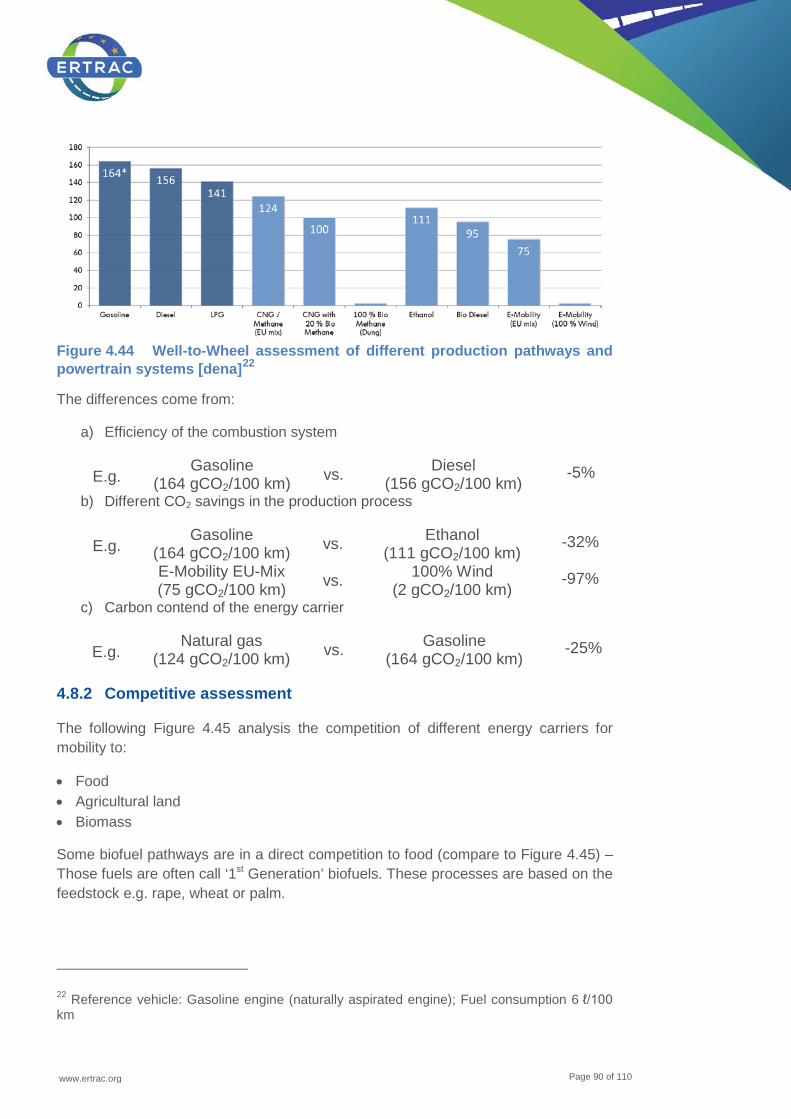
www.ertrac.org
Page 90 of 110
Figure 4.44 Well-to-Wheel assessment of different production pathways and powertrain systems [dena]22
The differences come from:
a) Efficiency of the combustion system
E.g. Gasoline
(164 gCO2/100 km) vs. Diesel (156 gCO2/100 km)
-5%
b) Different CO2 savings in the production process
E.g. Gasoline
(164 gCO2/100 km) vs. Ethanol (111 gCO2/100 km)
-32%
E-Mobility EU-Mix (75 gCO2/100 km) vs. 100% Wind
(2 gCO2/100 km) -97%
c) Carbon contend of the energy carrier
E.g. Natural gas
(124 gCO2/100 km) vs. Gasoline (164 gCO2/100 km)
-25%
4.8.2 Competitive assessment
The following Figure 4.45 analysis the competition of different energy carriers for mobility to:
• Food • Agricultural land • Biomass
Some biofuel pathways are in a direct competition to food (compare to Figure 4.45) – Those fuels are often call ‘1st Generation’ biofuels. These processes are based on the feedstock e.g. rape, wheat or palm.
22 Reference vehicle: Gasoline engine (naturally aspirated engine); Fuel consumption 6 ℓ/100 km

www.ertrac.org
Page 91 of 110
Figure 4.45 Competitive assessment of renewable energy [Volkswagen AG]
When land is used to produce non-food biomass for the biofuel production (e.g. corn, switch grass, short rotation plants or wood) there is no direct impact on food but there is competition on land use which may also affect food prices.
Biofuels produced from residuals, e.g. from the agriculture, like straw from the wheat production, are not in competition to food or use of land. The only lasting completion is on the biomass itself, which could be e.g. used for heating purpose.
Rivalry can be overcome, when “green” electricity or direct conversion of sunlight to fuels (via algae or microorganisms, see e.g. paragraph 4.4.7) reaches high efficiencies and low costs.
The fuels out of the last two categories are the most promising approaches to guarantee a sustainable feedstock. Research is needed here.

www.ertrac.org
Page 92 of 110
4.8.3 Technological assessment of different pathways
Table 4.6 Industrial status of different renewable energy production pathways
The Table 4.6 gives an overview of different criteria to assess the various describes pathways. The following criteria are qualitatively analysed:
• Industrial status of different renewable energy production pathways: • This parameter indicates the industrial status of the different pathways and refers
to existing facilities in different scales: Research, Pilot/ Demo and Industrial • Number of processes/ investment in process technology:
Ener
gy p
rodu
ctio
n pa
thw
ays
/ pro
cess
esFu
el ty
pe
Research
Pilot / Demo
Commercial
complex
medium
easy
little
medium
many
Hyd
ro T
reat
ed V
eget
able
Oils
(H
VO
)D
iese
lX
XX
Dim
ethy
l Eth
er (D
ME
)D
iese
lX
XX
Bio
mas
s to
liqu
id (B
tL)
Die
sel /
G
asol
ine
XX
X
Sug
ar to
Die
sel
Die
sel
XX
X
Sug
ar to
Eth
anol
(or h
ighe
r al
coho
ls)
Gas
olin
eX
XX
Bio
mas
s pr
oduc
tion
by A
lgea
te
chnl
ogie
sD
iese
l /
Gas
olin
eX
XX
Bio
tech
nolo
gica
l fue
l pr
oduc
tion
(e.g
. Alg
ea, e
-Col
i, D
iese
lX
XX
Pow
er-to
-liqu
idD
iese
l /
Gas
olin
eX
XX
Met
hyl-t
ert-b
utyle
ther
(MTB
E)
via
Met
hano
lG
asol
ine
XX
X
Met
hano
l, re
new
able
Die
sel /
G
asol
ine
XX
X
Tailo
r mad
e fu
els
from
bi
omas
sD
iese
lX
XX
Oxy
met
al te
chno
logi
esX
X
Bio
Met
hane
(CH
4)M
etha
neX
XX
Alg
ae M
etha
ne (C
H4)
Met
hane
XX
X
Pow
er to
Met
hane
(CH
4)M
etha
neX
XX
Mix
ture
s of
Met
hane
and
H
ydro
gen
(CH
4 + H
2)M
etha
ne +
H
2X
XX
Hyd
roge
n (H
2)M
etha
ne +
H
2X
XX
Liqu
ide
Air
XX
X
Indu
stria
l sta
tus
of d
iffer
ent
rene
wab
le e
nerg
y pr
oduc
tion
path
way
s
Num
ber o
f pro
cess
es /
inve
stm
ent i
n pr
oces
s te
chno
logy
Num
ber o
f pos
sibl
e fe
edst
ocks
fo
r the
pat
hway
s
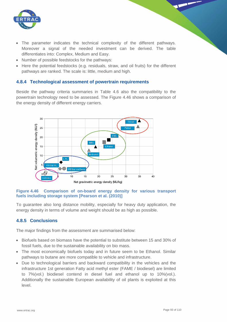
www.ertrac.org
Page 93 of 110
• The parameter indicates the technical complexity of the different pathways. Moreover a signal of the needed investment can be derived. The table differentiates into: Complex, Medium and Easy.
• Number of possible feedstocks for the pathways: • Here the potential feedstocks (e.g. residuals, straw, and oil fruits) for the different
pathways are ranked. The scale is: little, medium and high.
4.8.4 Technological assessment of powertrain requirements
Beside the pathway criteria summaries in Table 4.6 also the compatibility to the powertrain technology need to be assessed. The Figure 4.46 shows a comparison of the energy density of different energy carriers.
Figure 4.46 Comparison of on-board energy density for various transport fuels including storage system [Pearson et al. (2010)]
To guarantee also long distance mobility, especially for heavy duty application, the energy density in terms of volume and weight should be as high as possible.
4.8.5 Conclusions
The major findings from the assessment are summarised below:
• Biofuels based on biomass have the potential to substitute between 15 and 30% of fossil fuels, due to the sustainable availability on bio mass.
• The most economically biofuels today and in future seem to be Ethanol. Similar pathways to butane are more compatible to vehicle and infrastructure.
• Due to technological barriers and backward compatibility in the vehicles and the infrastructure 1st generation Fatty acid methyl ester (FAME / biodiesel) are limited to 7%(vol.) biodiesel contend in diesel fuel and ethanol up to 10%(vol.). Additionally the sustainable European availability of oil plants is exploited at this level.
www.ertrac.org
Page 94 of 110
• In the overall economic assessment costs for fuel production, and in addition, costs for possible new infrastructure and new vehicles have to be taken into account. In this respect drop-in fuels offer substantial benefit.
• To extend biogenous diesel components pathways to drop-in fuels are in the focus (E.g. HVO, sugar to diesel, BtL). The feedstock will be based on residuals.
• Captured fleets offer the potential to bring higher blends of biofuels (like e.g. E20 and B7) into the market.
• Methanol and DME have to potential to be a cost efficient way to become fuels in dedicated fleets of HD transports, busses and ships as well as, for methanol, as a blend component in gasoline in captured fleets.
• Natural gas offers the possibility to overcome the blend wall discussion. No matter where the molecule methane (CH4) comes from (bio methane or power-to-gas methane), it can be injected into the network or liquefied and used in all CNG and LNG vehicles in any volume without limitation.
• CNG and LNG from fossil and renewable sources represent an effective and relative near-term way to decarbonise and reduce regulated emissions the European transport sector and deserve specific immediate attention.
• LPG on the other hand is a dead-end fuel in terms of research needs. • Green electricity is the very promising feedstock for energy carries for mobility in
the future. The electricity might be used in batteries or converted to chemical energy carriers (e.g. power-to-gas methane, hydrogen or liquids).
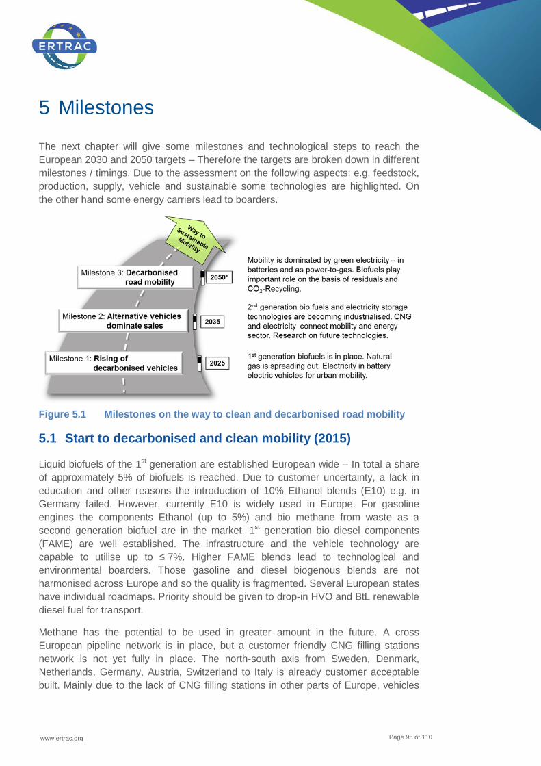
www.ertrac.org
Page 95 of 110
5 Milestones
The next chapter will give some milestones and technological steps to reach the European 2030 and 2050 targets – Therefore the targets are broken down in different milestones / timings. Due to the assessment on the following aspects: e.g. feedstock, production, supply, vehicle and sustainable some technologies are highlighted. On the other hand some energy carriers lead to boarders.
Figure 5.1 Milestones on the way to clean and decarbonised road mobility
5.1 Start to decarbonised and clean mobility (2015)
Liquid biofuels of the 1st generation are established European wide – In total a share of approximately 5% of biofuels is reached. Due to customer uncertainty, a lack in education and other reasons the introduction of 10% Ethanol blends (E10) e.g. in Germany failed. However, currently E10 is widely used in Europe. For gasoline engines the components Ethanol (up to 5%) and bio methane from waste as a second generation biofuel are in the market. 1st generation bio diesel components (FAME) are well established. The infrastructure and the vehicle technology are capable to utilise up to ≤ 7%. Higher FAME blends lead to technological and environmental boarders. Those gasoline and diesel biogenous blends are not harmonised across Europe and so the quality is fragmented. Several European states have individual roadmaps. Priority should be given to drop-in HVO and BtL renewable diesel fuel for transport.
Methane has the potential to be used in greater amount in the future. A cross European pipeline network is in place, but a customer friendly CNG filling stations network is not yet fully in place. The north-south axis from Sweden, Denmark, Netherlands, Germany, Austria, Switzerland to Italy is already customer acceptable built. Mainly due to the lack of CNG filling stations in other parts of Europe, vehicles
www.ertrac.org
Page 96 of 110
are bivalent and can additionally run on gasoline. Important markets like France, Spain or Poland slowly start to catch up with regards to developing a denser public natural gas refuelling network.
For heavy duty application first terminals/ filling stations for liquefied natural gas (LNG) are under construction and in use in parts of Europe, first Corridors are being established (e.g. LNG Blue Corridor FP7 project).
Green electricity is produced in significant amounts - First battery electric vehicles are on the road in Europe (some ten thousands of vehicles). Many vehicle manufacturers have announced and commercialize new alternative vehicles. EV partnerships are spreading up between cities, EV manufacturers and energy producers. First charging stations for electrically chargeable vehicles have been established, plans for further buildup of charging stations are under developed in a number of EU member states. First hydrogen filling stations have been built up in some EU member states.
The insufficient grid/ network and volatile production indicate the need for storage technology development and major grid enhancement. Here a synergy between the energy sector and the mobility is coming up effectively, when surplus of green electricity occurs, it can be stored in power-to-gas methane or hydrogen or directly in batteries (power to battery).
5.2 Milestone 1: Rising of decarbonised vehicles (2025) - [Market 2028 - 2030]
The engine technology is optimised and higher efficiencies are achieved (+ 2%) with new higher biofuel blends of alcohol. Those bends need to be introduced in high qualities and harmonised across Europe. Blend rates of Ethanol up to 20% might come into the market.
Production pathways to biogenic diesel components are more diverse: 7% of FAME is still in the market and additional substitution potential comes from drop-in diesel components (e.g. HVO and paraffinic components, BtL). Drop-in HVO production capacity has expanded. More and more feedstocks come from residuals and those are co-processed in refineries or produced by standalone plants. The same feedstock platform as for ethanol is used for diesel: sugar-to-diesel technology on the basis of residuals. These are the first commercialised 2nd generation bio fuel plants. Future technologies, like ‘CO2 + Sunlight’ to fuels is under research and demonstration.
Due to the European initiative on alternative energy carriers the natural gas filling station network has expanded strongly. Also the west-east axis in Europe is acceptable developed. Due to the availability of natural gas in each European country, the engines (based on a gasoline combustion system) are designed for monovalent application, which lead to > 2% higher efficiency. The market share of new registered natural gas cars increases and may reach 10%. The decarbonisation of natural gas is expanding – 20% of the used natural gas is coming from

www.ertrac.org
Page 97 of 110
decarbonised sources; mainly from bio methane, but the several industrial power-to-gas plants are running supplying.
For heavy duty application a filling station network along the European core network (TEN-T) with liquefied natural gas and liquefied biogas blends (LNG) is available. In heavy duty urban vehicles, i.e. buses, garbage and delivery trucks, bio CNG is an interesting choice with an increasing market share of up to 30% in newly registered CNG buses and trucks, including gas hybrids. Other alternative fuels such as DME, are available in certain parts of EU. In this way, a limited number of alternative fuel filling stations are required to supply a captured vehicle fleet.
E-Mobility is playing a major role in urban and start to do in suburban areas – even as battery electric vehicles or as plug-in hybrid vehicles. More than 10% of new registered vehicles have the capability to run at least 50 km (plug in hybrids) up to 250 km (battery electric vehicles) on electricity stored in batteries. The vehicle batteries are connected to electrical grid which helps to stabilise it (smart grid) and offer large capacities to store directly green electricity. Fast charging infrastructures have been deployed. EVs are able to travel on designated highways.
The European network of hydrogen filling station has grown significantly, hydrogen fuelled vehicles are able to travel in the core of the EU member states via corridors. In remote areas, the density of hydrogen filling stations is still low. Fuel cell electric vehicles begin to have an important share in new cars sales numbers.
In total the market share of new registered alternative vehicles has reached 12%.
5.3 Milestone 2: Alternative vehicles dominate sales to approach 50% CO2 reduction (2035) - [Market 2038 - 2040]
Due to sustainable available bio mass, liquid and gaseous biofuels have reached a limit to substitute 20% fossil fuels. The biomass is converted into biofuels in 2nd generation plants. The infrastructure and vehicle technology is compatible.
First plants to overcome the availability of bio mass are in place. Desert like land and salt water is used to produce fuels from ‘Sunlight and CO2’ in microorganisms. The product can be ethanol, higher alcohols or drop-in diesel components. The engines are hybridised and optimised to use the high quality drop-in fuels.
Electrified vehicles represent up to 33% of all vehicles sales and green electricity is available through a large recharging infrastructure, as well as renewable hydrogen by a dense network of hydrogen filling stations.
CNG, including hybrids is very well established in the mobility sector. The share has reached 33% of new registered vehicles. For heavy duty application LNG has become a second pillar beside diesel. The last infrastructure gaps for CNG and LNG refuelling are filled.

www.ertrac.org
Page 98 of 110
The potential of decarbonised electricity is still significant. Storage technology (new batteries and power-to-gas methane or hydrogen) has closed the gap between the electricity and mobility sector. E.g. electrified vehicles are fully integrated into the energy management of households as well as of positive energy buildings, through the smart grid. By storing electricity in chemical energy carriers (e.g. power-to-gas methane or hydrogen), long distance mobility with energy carries coming from renewable electricity is available.
For HD vehicles the full electric vehicles come to play only in city distribution and buses, while for the majority HD vehicles a range of solutions including blend-in, mono bio-fuels and continuous electric grid systems for dedicated LH application. The bio fuel qualities used are now fully defined.
In total the market share of new registered alternative vehicles has the potential to approach 50%.
5.4 Milestone 3: Decarbonized and clean road mobility to obtain 60% CO2 reduction (2050) - [Market 2050+]
Still, liquid and gaseous biofuels give an important contribution to the energy used in mobility – This is e.g. due to the high energy density of liquid and even gaseous fuels. Powertrains are optimised for the most available renewable monofuels.
Overall renewable electricity became the most important source as energy carrier for mobility. Battery technology has further developed in high capacity, light weight and low costs. A significant (> 60%) proportion of all passenger car trips are covered by battery electric power. All of Europe has a sufficient coverage of recharging infrastructure.
By power-to-gas technologies the amount of electricity used in mobility is opened (power-to-gas methane and hydrogen). Additionally the energy density is acceptable for mobile long distance application – in all modes of road mobility.
Methane is playing relevant role: On one hand the availability is still secured by fossil sources, on the other hand no blend wall covers the injection of decarbonised components. Those are produced form residuals to bio methane or from ‘green electricity’ to power-to-gas methane. The overall market share of new CNG and LNG registered vehicles, including hybrids, for passenger and freight transport has continued to increase. All of Europe has a sufficient coverage of methane refuelling.
For HD vehicles a fully developed distribution net of renewable fuel and rapid HD vehicle charging stations and an EU network of electric roads, supplies a significant part of the HD transportation operations. The HD renewable mono-fuel network is established with a minimal set of qualities.
The goal to decarbonise 60% of the mobility is reached.
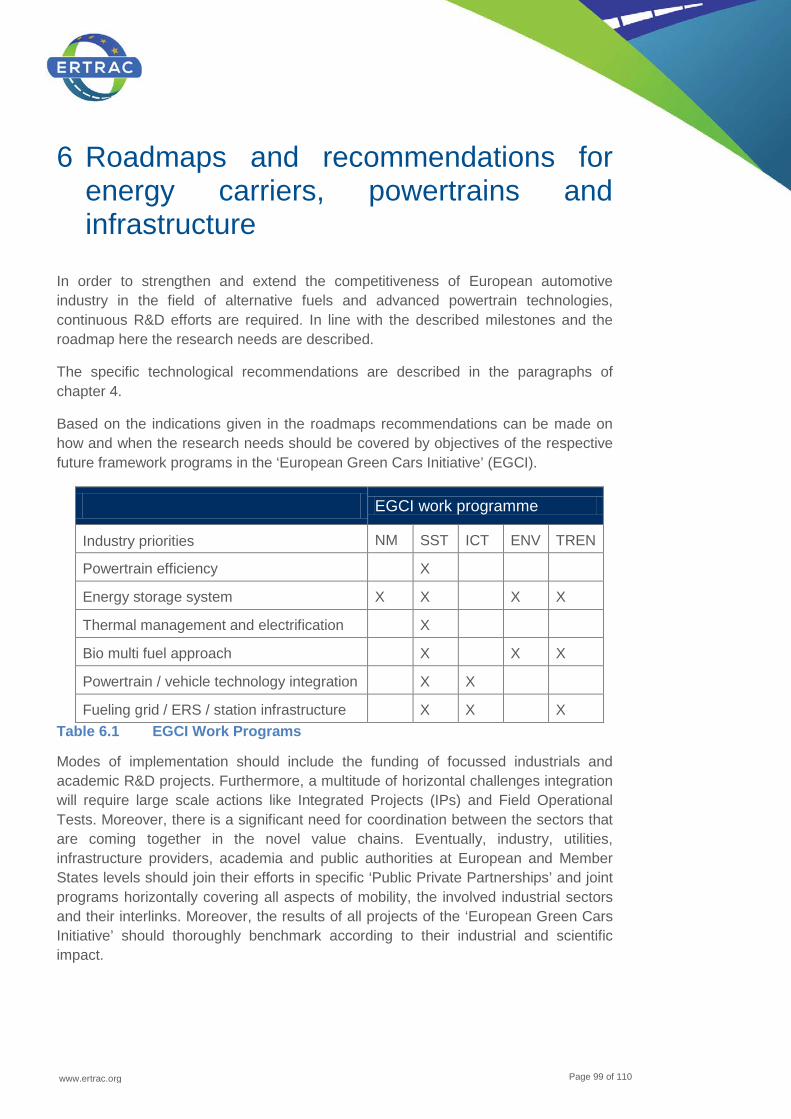
www.ertrac.org
Page 99 of 110
6 Roadmaps and recommendations for energy carriers, powertrains and infrastructure
In order to strengthen and extend the competitiveness of European automotive industry in the field of alternative fuels and advanced powertrain technologies, continuous R&D efforts are required. In line with the described milestones and the roadmap here the research needs are described.
The specific technological recommendations are described in the paragraphs of chapter 4.
Based on the indications given in the roadmaps recommendations can be made on how and when the research needs should be covered by objectives of the respective future framework programs in the ‘European Green Cars Initiative’ (EGCI).
EGCI work programme
Industry priorities NM
SST ICT ENV TREN
Powertrain efficiency X
Energy storage system X X X X
Thermal management and electrification X
Bio multi fuel approach X X X
Powertrain / vehicle technology integration X X
Fueling grid / ERS / station infrastructure X X X Table 6.1 EGCI Work Programs
Modes of implementation should include the funding of focussed industrials and academic R&D projects. Furthermore, a multitude of horizontal challenges integration will require large scale actions like Integrated Projects (IPs) and Field Operational Tests. Moreover, there is a significant need for coordination between the sectors that are coming together in the novel value chains. Eventually, industry, utilities, infrastructure providers, academia and public authorities at European and Member States levels should join their efforts in specific ‘Public Private Partnerships’ and joint programs horizontally covering all aspects of mobility, the involved industrial sectors and their interlinks. Moreover, the results of all projects of the ‘European Green Cars Initiative’ should thoroughly benchmark according to their industrial and scientific impact.

www.ertrac.org
Page 100 of 110
6.1 Roadmaps for energy carriers
Following the definitions of milestones, the involved companies and organisations from ERTRAC and NGVA agreed on actions to be taken in order to achieve the stated objectives. Considering phases of R&D, production and market introduction as well as the establishment of regulatory frameworks, dedicated roadmaps were drafted. Those indicate what has to be done when for a well-timed move of Europe towards the hybridisation and thus the electrification of road transport.
The explanation of the arrows used in the roadmaps is given below:
Research & Development
Production & Market
Regulatory Framework
Milestone
2015 2025 2035 2050
Gasoline Biofuels Blends23 Ethanol 5 / 10% Ethanol 20%
Optimised engines for higher alcohol blends
Higher Alcohols
Diesel Biofuels Blends23 2015 2025 2035 2050
FAME 7% Drop-In24 Diesel
HVO
Optimised engines for drop-in fuels
Sugar-to-fuel 2015 2025 2035 2050
Gasoline
23 Blends are Mixtures of fossil based fuel products and bio components. The infrastructure and vehicle technology need to be adapted to theses fuels (except for drop-in components). 24 Drop-In components are compatible to vehicles and infrastructure (definition, see page 32)
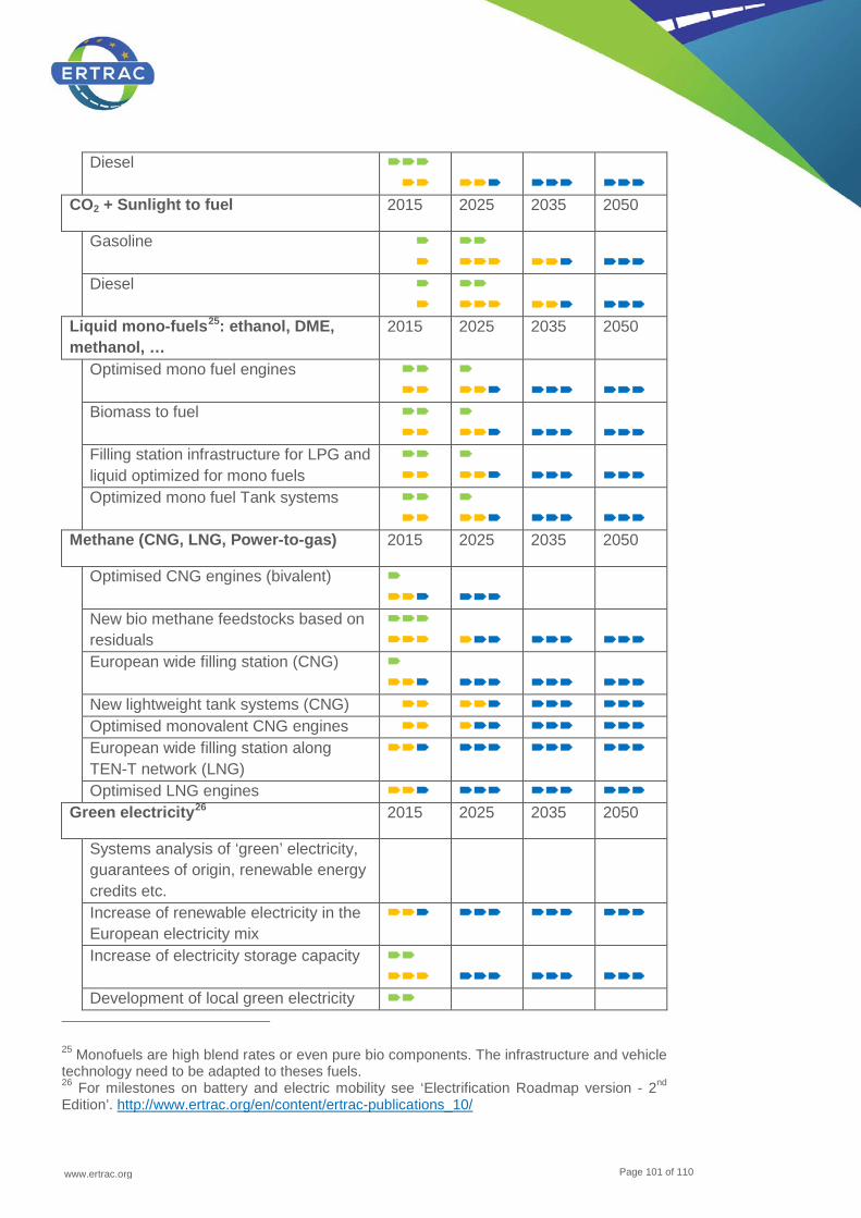
www.ertrac.org
Page 101 of 110
Diesel
CO2 + Sunlight to fuel 2015 2025 2035 2050
Gasoline
Diesel
Liquid mono-fuels25: ethanol, DME, methanol, …
2015 2025 2035 2050
Optimised mono fuel engines
Biomass to fuel
Filling station infrastructure for LPG and liquid optimized for mono fuels
Optimized mono fuel Tank systems
Methane (CNG, LNG, Power-to-gas) 2015 2025 2035 2050
Optimised CNG engines (bivalent)
New bio methane feedstocks based on residuals
European wide filling station (CNG)
New lightweight tank systems (CNG) Optimised monovalent CNG engines European wide filling station along
TEN-T network (LNG)
Optimised LNG engines Green electricity26 2015 2025 2035 2050
Systems analysis of ‘green’ electricity, guarantees of origin, renewable energy credits etc.
Increase of renewable electricity in the European electricity mix
Increase of electricity storage capacity
Development of local green electricity
25 Monofuels are high blend rates or even pure bio components. The infrastructure and vehicle technology need to be adapted to theses fuels. 26 For milestones on battery and electric mobility see ‘Electrification Roadmap version - 2nd Edition’. http://www.ertrac.org/en/content/ertrac-publications_10/
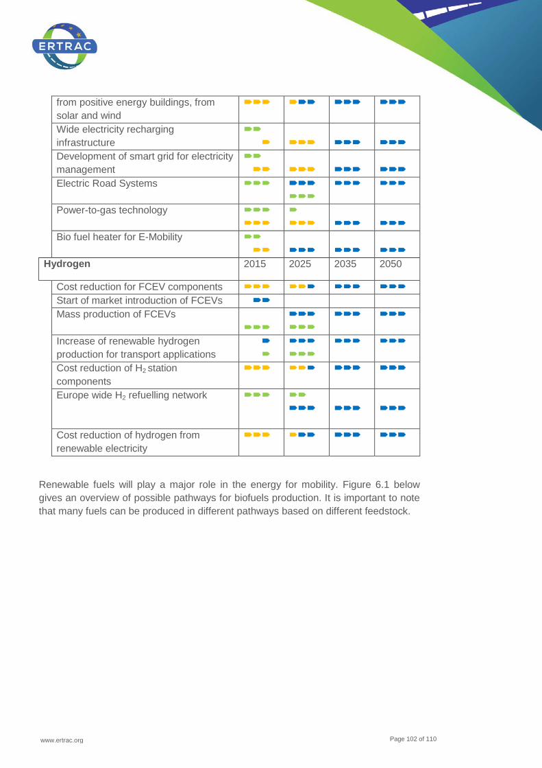
www.ertrac.org
Page 102 of 110
from positive energy buildings, from solar and wind
Wide electricity recharging infrastructure
Development of smart grid for electricity management
Electric Road Systems
Power-to-gas technology
Bio fuel heater for E-Mobility
Hydrogen 2015 2025 2035 2050
Cost reduction for FCEV components Start of market introduction of FCEVs Mass production of FCEVs
Increase of renewable hydrogen production for transport applications
Cost reduction of H2 station components
Europe wide H2 refuelling network
Cost reduction of hydrogen from renewable electricity
Renewable fuels will play a major role in the energy for mobility. Figure 6.1 below gives an overview of possible pathways for biofuels production. It is important to note that many fuels can be produced in different pathways based on different feedstock.
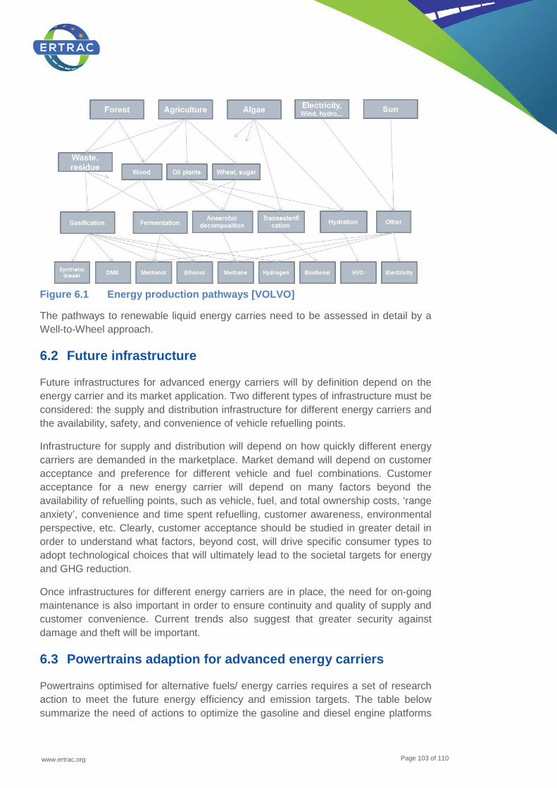
www.ertrac.org
Page 103 of 110
Figure 6.1 Energy production pathways [VOLVO]
The pathways to renewable liquid energy carries need to be assessed in detail by a Well-to-Wheel approach.
6.2 Future infrastructure
Future infrastructures for advanced energy carriers will by definition depend on the energy carrier and its market application. Two different types of infrastructure must be considered: the supply and distribution infrastructure for different energy carriers and the availability, safety, and convenience of vehicle refuelling points.
Infrastructure for supply and distribution will depend on how quickly different energy carriers are demanded in the marketplace. Market demand will depend on customer acceptance and preference for different vehicle and fuel combinations. Customer acceptance for a new energy carrier will depend on many factors beyond the availability of refuelling points, such as vehicle, fuel, and total ownership costs, ‘range anxiety’, convenience and time spent refuelling, customer awareness, environmental perspective, etc. Clearly, customer acceptance should be studied in greater detail in order to understand what factors, beyond cost, will drive specific consumer types to adopt technological choices that will ultimately lead to the societal targets for energy and GHG reduction.
Once infrastructures for different energy carriers are in place, the need for on-going maintenance is also important in order to ensure continuity and quality of supply and customer convenience. Current trends also suggest that greater security against damage and theft will be important.
6.3 Powertrains adaption for advanced energy carriers
Powertrains optimised for alternative fuels/ energy carries requires a set of research action to meet the future energy efficiency and emission targets. The table below summarize the need of actions to optimize the gasoline and diesel engine platforms
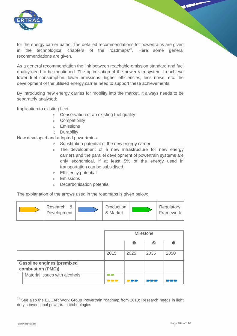
www.ertrac.org
Page 104 of 110
for the energy carrier paths. The detailed recommendations for powertrains are given in the technological chapters of the roadmaps27. Here some general recommendations are given.
As a general recommendation the link between reachable emission standard and fuel quality need to be mentioned. The optimisation of the powertrain system, to achieve lower fuel consumption, lower emissions, higher efficiencies, less noise, etc. the development of the utilised energy carrier need to support these achievements.
By introducing new energy carries for mobility into the market, it always needs to be separately analysed:
Implication to existing fleet o Conservation of an existing fuel quality o Compatibility o Emissions o Durability
New developed and adopted powertrains o Substitution potential of the new energy carrier o The development of a new infrastructure for new energy
carriers and the parallel development of powertrain systems are only economical, if at least 5% of the energy used in transportation can be subsidised.
o Efficiency potential o Emissions o Decarbonisation potential
The explanation of the arrows used in the roadmaps is given below:
Research & Development
Production & Market
Regulatory Framework
Milestone
2015 2025 2035 2050
Gasoline engines (premixed combustion (PMC))
Material issues with alcohols
27 See also the EUCAR Work Group Powertrain roadmap from 2010: Research needs in light duty conventional powertrain technologies
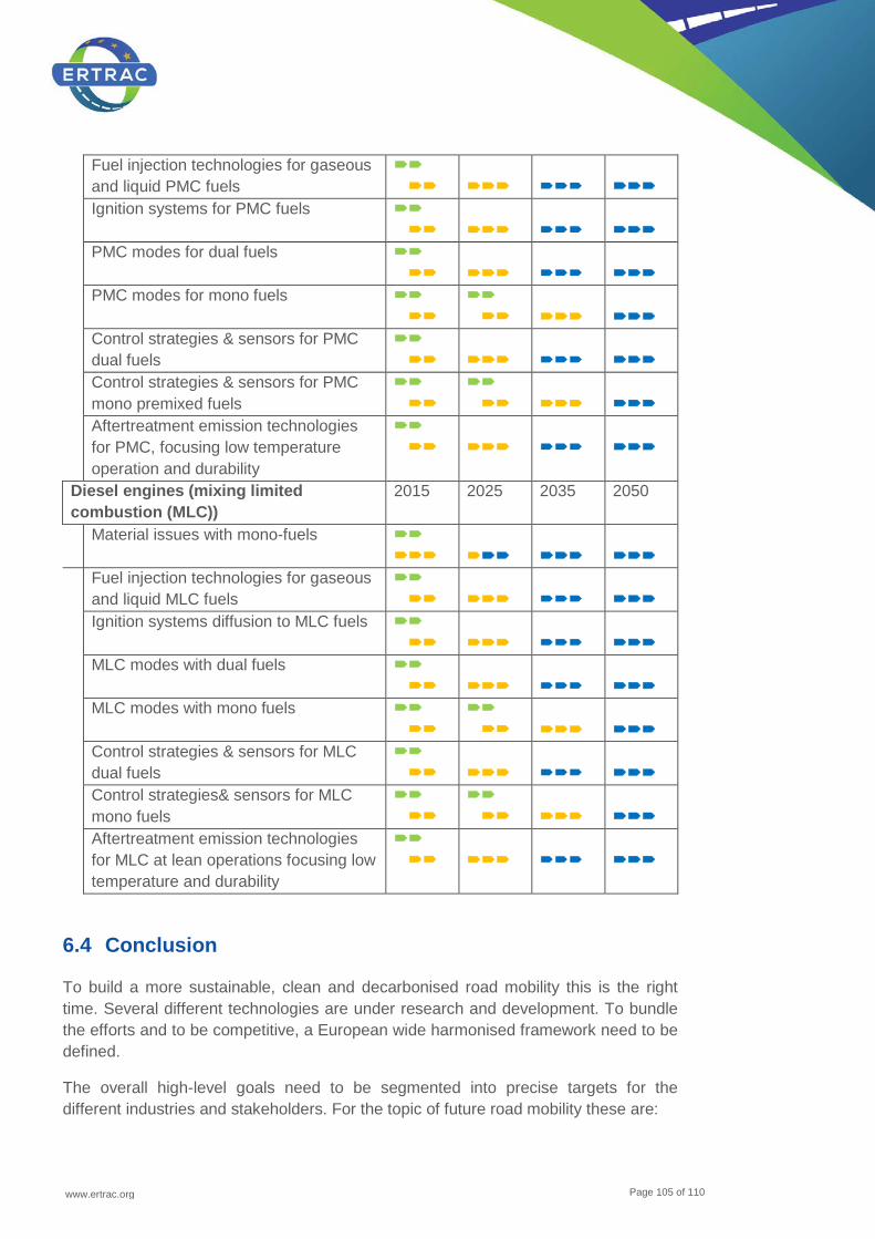
www.ertrac.org
Page 105 of 110
Fuel injection technologies for gaseous and liquid PMC fuels
Ignition systems for PMC fuels
PMC modes for dual fuels
PMC modes for mono fuels
Control strategies & sensors for PMC dual fuels
Control strategies & sensors for PMC mono premixed fuels
Aftertreatment emission technologies for PMC, focusing low temperature operation and durability
Diesel engines (mixing limited combustion (MLC))
2015 2025 2035 2050
Material issues with mono-fuels
Fuel injection technologies for gaseous and liquid MLC fuels
Ignition systems diffusion to MLC fuels
MLC modes with dual fuels
MLC modes with mono fuels
Control strategies & sensors for MLC dual fuels
Control strategies& sensors for MLC mono fuels
Aftertreatment emission technologies for MLC at lean operations focusing low temperature and durability
6.4 Conclusion
To build a more sustainable, clean and decarbonised road mobility this is the right time. Several different technologies are under research and development. To bundle the efforts and to be competitive, a European wide harmonised framework need to be defined.
The overall high-level goals need to be segmented into precise targets for the different industries and stakeholders. For the topic of future road mobility these are:

www.ertrac.org
Page 106 of 110
• Production and supply of decarbonised energy carriers • Increased efficiency during usage
The regulatory framework should break down the overall targets to different industries. These targets need to be reliable to secure high effort and progress. The priority of decarbonizing transport will be based on cost-effective low carbon electricity and biofuels when optimizing the whole value chain from fuel production, infrastructure and vehicle fleet.
www.ertrac.org
Page 107 of 110
7 References
• Alger T.: Dedicated EGR™ - A High Efficiency, Low Emissions Concept for SI Engines. SAE High Efficiency Engine Symposium, Detroit 2013
• Andreae-Jäckering, Brüschke, Kazemekas, Tusel: Has Butanol the potential to become the biofuel No. 1?: 6th World Bioenergy Symposium (2012)
• Assessment of Net Emissions of Greenhouse Gases from Ethanol-Gasoline Blends in Southern Ontario (Levelton Engineering Ltd. and (S&T) 2 Consulting Inc., 1999)
• Bechtold, R. L. (1997) Alternative Fuels Guidebook - Properties, Storage, Dispensing, and Vehicle Facility Modifications. Society of Automotive Engineers, Inc.
• Bechtold, R., Goodman, M. and Timbario, T. (2007) Use of Methanol as a Transportation Fuel. Report prepared for Methanol Institute.
• Bromberg, L. and Cheng, W. (2010) Methanol as an alternative transportation fuel in the US: Options for sustainable and/or energy- secure transportation. Final report. UT-Battelle Subcontract Number:4000096701
• Chang, J.; Kalghatgi, G.; Amer, A.; Adomeit, P. Rohs, H.; Heuser, B.; Vehicle Demonstration of Naphtha Fuel Achieving Both High Efficiency and Drivability with EURO6 Engine-Out NOx Emission; SAE paper 2013-01-0267; 2013
• CORE FP7 DG Research project • Daynard; What do Canadian Commitments on Greenhouse Gas Emissions mean
for Agriculture; 1998, Ontario Corn Producers' Association, http://www.ontariocorn.org/greenhou.html
• DG Move; LNG Blue corridors FP7 project • DG Research; GASTONE FP7 project proposal • DG Research; INGAS FP7 project • DG Research; More efficient – less polluting Report 2011 • Doidge and Burgess; Corn Ethanol in Ontario: A Profile of Ontario's Corn Ethanol
Industry (1996, Ridgetown Agricultural College) • EBTP Fact Sheet on bio-ethanol • EBTP SRA Update 2010 • EBTP SRA Update 2012 • EC, 2011a, White Paper 'Roadmap to a Single European Transport Area -
Towards a competitive and resource efficient transport system' (COM(2011) 144 final). http://eur-lex.europa.eu/LexUriServ/LexUriServ.do?uri=COM:2011: 0144:FIN:EN:PDF
• EC, 2013, Clean Power for Transport: A European alternative fuels strategy, 2013; http://ec.europa.eu/transport/themes/urban/cpt/
• EEA Report No 10/2012. The contribution of transport to air quality • EGCI Ad-hoc Industrial Advisory Group of the European Green Cars Initiative
PPP; Multi-annual roadmap and long-term strategy, November 2010
www.ertrac.org
Page 108 of 110
• Emissions Performance of Ethanol-Containing Transportation Fuels (Prakash and Wachmann, 1989, Environment Canada)
• ERTRAC Strategic Research Agenda 2010; Towards a 50% more efficient road transport system by 2030, May 2010
• ERTRAC, EPoSS, SmartGrids; European Roadmap Electrification of Road Transport; October 2009
• EU renewable energy targets in 2020: Analysis of scenarios for transport - JEC Biofuels Program
• Eurogas Roadmap 2050 • European Gas Forum. Decarbonisation of the Transportation Sector to 2050 • Eurostat, 2012. Eurostat Statistical Database, Eurostat, Luxembourg,
http://epp.eurostat.ec.europa.eu/portal/page/portal/transport/data/database • Expert Group on Future Transport Fuels, DG MOVE • FNR – Bioenergy – Plants, Raw materials, Products 2009 • FNR – Biofuels – Plants, Raw materials, Products 2006 • FNR – Guide to Biogas - From production to use 2010 • Fuel Cycle Fossil Energy Use and Greenhouse Gas Emissions of Corn and
Cellulosic Ethanol (Wang, 1998, Argonne National Laboratory) • G. Petkov, A. Ivanovova, I. Iliev, I. Vaseva: A critical look at the microalgae
biodiesel, Eur. J. Lipid Sci. Technology 2012 • Graboski, M. (1999) Tautomerism and octane quality in carbonyl-containing
oxygenates. Ind. Eng. Chem. Res. 38(1999)3776-3778. • Graves 2011; Sustainable hydrocarbon fuels by recycling CO2 and H2O with
renewable or nuclear energy, Christopher Graves, Sune D. Ebbesen, Mogens Mogensen, and Klaus S. Lackner, Renewable and Sustainable Energy Reviews 15 (2011) 1–23
• Green Car Advisor (2009) China Approves Methanol as Clean-Burning Alternative to Gasoline. 10 November 2009. blogs.edmunds.com.
• Hofmann, L.; Leohold, J.; Steiger, W.; Böhm, T.; Volkswagen AG, Wolfsburg; twinDrive – Ein Schritt in Richtung Elektromobilität
• http://www.ngvaeurope.eu/eurogas-roadmap-2050-natural-gas-vehicles-should-reach-a-market-share-of-13-and-33-respectively-for-passenger-and-freight-transport
• http://www.ngvaeurope.eu/eurogas-roadmap-2050-natural-gas-vehicles-should-reach-a-market-share-of-13-and-33-respectively-for-passenger-and-freight-transport
• http://www.ngvaeurope.eu/european-gas-forum-study-concludes-greater-use-of-ngvs-will-meet-co2-abatement-targets-with-huge-cost-savings
• http://www.ngvaeurope.eu/european-gas-forum-study-concludes-greater-use-of-ngvs-will-meet-co2-abatement-targets-with-huge-cost-savings
• HVO, Hydrotreated Vegetable Oil - a Premium Renewable Biofuel for Diesel Engines. http://www.nesteoil.com/binary.asp?GUID=7A041F14-022A-4295-B1E4-1102585F5E3F

www.ertrac.org
Page 109 of 110
• HVO, Hydrotreated Vegetable Oil - a Premium Renewable Biofuel for Diesel Engines. 9th International Colloquium Fuels - Conventional and Future Energy for Automobiles. Technische Akademie Esslingen, Ostfildern, 15. - 17.1.2013. In Fuels - Mineral Oil Based and Alternative Fuels, ISBN 98-3-943563-04-7, p. 281 - 291.
• IEA - Advanced Motor Fuels Annual Report 2011 • IEA - World Energy Outlook 2012 • Internetpage - www.methanol.org • Kalghatgi G.: The Outlook for Transport Fuels and GCI (Gasoline Compression
Ignition) Engines. SAE High Efficiency Engine Symposium, Detroit 2013 • Lorenz and Morris; How Much Energy Does it Take to Make a Gallon of Ethanol
(1995, Institute for Local Self-Reliance, http://www.ilsr.org/carbo/ethanol/netethan.html)
• Lösche-ter Horst; Seyfried; Krinke; Schmerbeck; Schmidt - Biofuels for sustainable mobility – Status of today and in future; Volkswagen AG, Wolfsburg
• Methanol Institute (2011). online www.methanol.org. • Methanol Institute a. Methanol Institute's Technical Product Bulletin: Methanol Use
in Gasoline - Blending, Storage and Handling of Gasoline Containing Methanol. Available online: http://www.methanol.org/.../Blending-Handling-Bulletin-(Final).aspx
• Methanol Institute b. Methanol Institute's Technical Product Bulletin: Methanol Gasoline Blends - Alternative Fuel For Today's Automobiles and Cleaner Burning Octane For Today's Oil Refinery. Available online: http://www.methanol.org/.../Blenders-Product- Bulletin-(Final).aspx
• More efficient – less polluting DG Research Report 2011Ferrera, M.; CRF Powertrain Research & Technologies; “Alternative fuel engines for public transportation”, Rome June 2010 – NGV 2010
• Nichols, R. (2003) The Methanol Story: A Sustainable Fuel for the Future. Journal of Scientific & Industrial Research. Vol. 62, p. 97 105.
• ODYSSEE-MURE, 2009. Energy Efficiency Trends and Policies in the EU 27 Results of the ODYSSEE-MURE project.
• Ohlström, M., Mäkinen, T., Laurikko, J. and Pipatti, R. (2001) New concepts for biofuels in transportation. Biomass-based methanol production and reduced emissions in advanced vehicles. VTT Research Notes 2074.
• Owen, K. and Coley, T. (1995) Automotive fuels reference book. 2nd edition. Warrendale,
• Pearson, R., Turner, J. & Pitcher, G. (2010). Fueling the future: Carbon-neutral fuels from air, water, and renewable energy. Lotus Engineering. Retrieved ; 5 February 2013 from http://81.29.73.156/~eeegrdev99/uploads/DOCS/778-20100726131932.pdf
• Reitz, R. D.: Reactivity Controlled Compression Ignition (RCCI) for ultra-high efficiency IC engine operation with low NOx and PM emissions plus transient control. SAE High Efficiency Engine Symposium, Detroit 2013
www.ertrac.org
Page 110 of 110
• Ricardo-AEA; Powering Ahead - The future of low-carbon cars and fuels, Duncan Kay; Nikolas Hill and Dan Newman; April 2013
• Rivkin, Radler, Dunne and Bayh; The Positive Impact of Ethanol Blends on the Environment (Direnfeld, 1989,)
• Rösch, C.; Posten, C.; Technikfolgenabschätzung – Theorie und Praxis 21. Jg., Heft 1, Juli 2012
• SAE (2007) Alternative Automotive Fuels. Surface Vehicle Information Report J1297. Society of Automotive Engineers.
• SAE; Current and Potential Future Performance of Ethanol Fuels (Sinor and Bailey, 1993, SAE Technical Paper Series)
• Splitter et al. “RCCI Engine Operation Towards 60% Thermal Efficiency”, SAE 2013-01-0279 and earlier papers, as Splitter, SAE 2010-01-2167; Hanson, SAE 2011-01-0361, etc.
• Steiger, W.; Volkswagen AG, Wolfsburg; twinDrive – Concept for Electrification of Powertrains
• Study of a portfolio of power-trains for Europe; a fact-based analysis; The role of Battery Electric Vehicles, Plug-In Hybrids and Fuel Cell Electric Vehicles
• Szybist J. P., Splitter D. A., Kalaskar V., Pihl J. A. and Daw C. S.: An Investigation Of Non‐Catalytic In‐Cylinder Fuel Reforming. SAE High Efficiency Engine Symposium, Detroit 2013
• Turner, J.W.G., Pearson, R.J., McGregor, M.A., Ramsay, J.M., Dekker, E., Iosefa, B., Dolan, G.A., Johansson, K. and Bergström, K. ac (2012) GEM Ternary blends
• Urban W.; Girod, K.; Lohmann, H., Technologien und Kosten der Biogasaufbereitung und Einspeisung in das Erdgasnetz, Ergebnisse der Markterhebung 2007-2008. Fraunhofer UMSICHT, 2008
• USA: Society of Automotive Engineers. 963 p. ISBN 1-56091-589-7.


