20
Page 27-1 Fusion-Welding Processes CHAPTER 7-1
| Date post: | 16-Dec-2015 |
| Category: |
Documents |
| Upload: | aileen-williams |
| View: | 238 times |
| Download: | 1 times |
Page 27-1
Fusion-Welding Processes
CHAPTER 7-1
Page 27-2
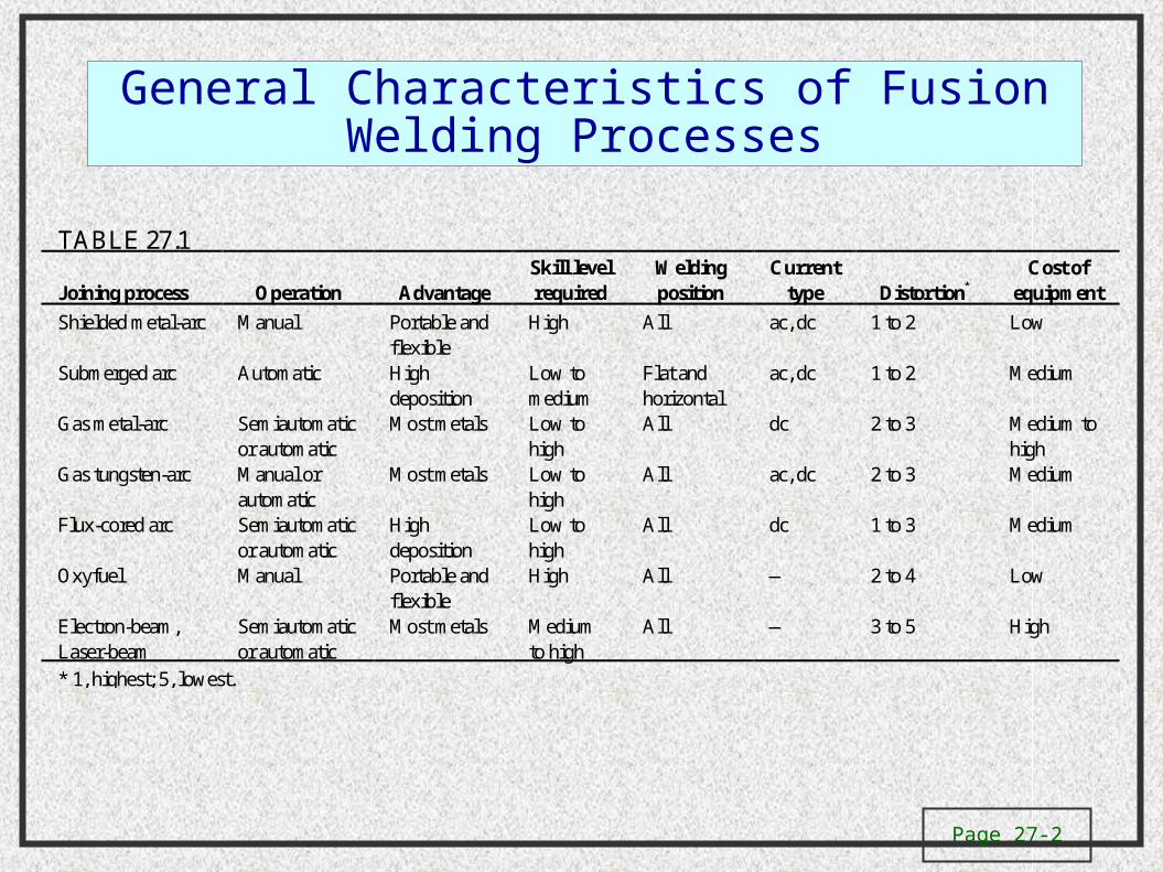
General Characteristics of Fusion Welding Processes
TABLE 27.1
Joining process Operation AdvantageSkill levelrequired
Weldingposition
Currenttype Distortion*
Cost ofequipment
Shielded metal-arc Manual Portable andflexible
High All ac, dc 1 to 2 Low
Submerged arc Automatic Highdeposition
Low tomedium
Flat andhorizontal
ac, dc 1 to 2 Medium
Gas metal-arc Semiautomaticor automatic
Most metals Low tohigh
All dc 2 to 3 Medium tohigh
Gas tungsten-arc Manual orautomatic
Most metals Low tohigh
All ac, dc 2 to 3 Medium
Flux-cored arc Semiautomaticor automatic
Highdeposition
Low tohigh
All dc 1 to 3 Medium
Oxyfuel Manual Portable andflexible
High All — 2 to 4 Low
Electron-beam,Laser-beam
Semiautomaticor automatic
Most metals Mediumto high
All — 3 to 5 High
* 1, highest; 5, lowest.
Page 27-3
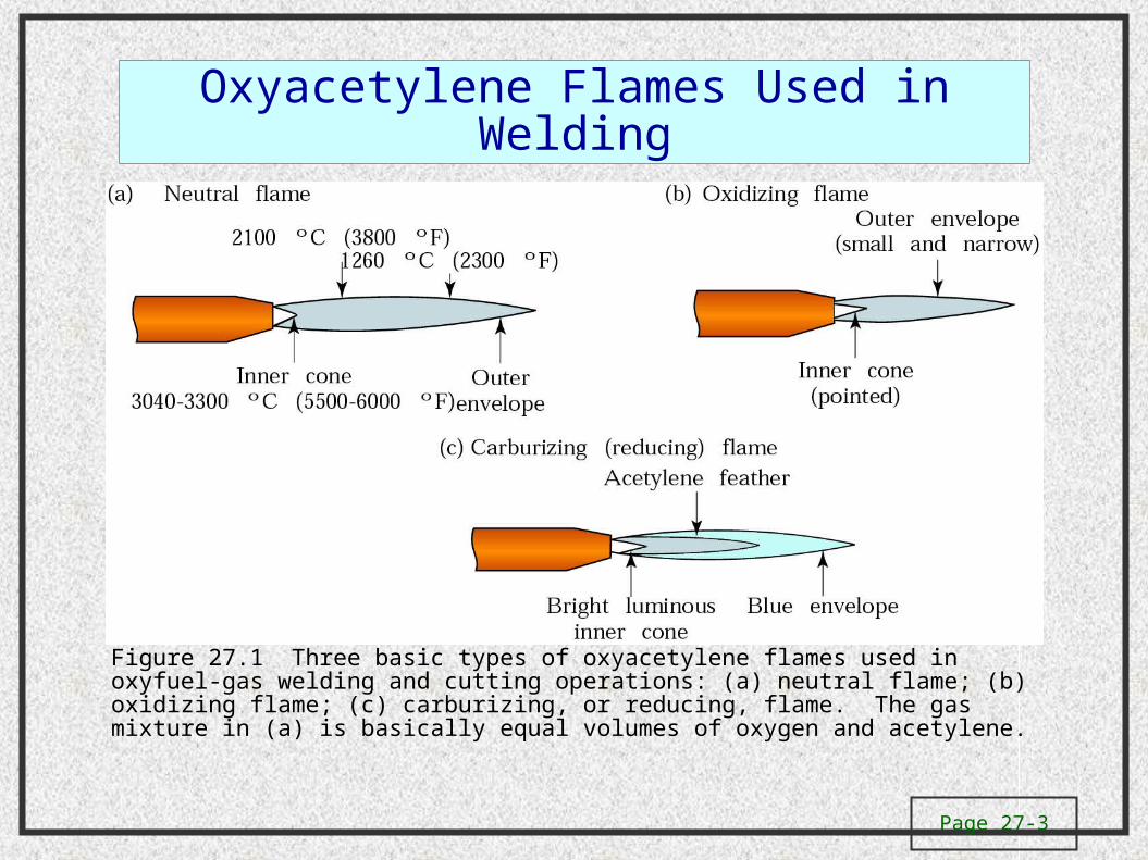
Oxyacetylene Flames Used in Welding
Figure 27.1 Three basic types of oxyacetylene flames used in oxyfuel-gas welding and cutting operations: (a) neutral flame; (b) oxidizing flame; (c) carburizing, or reducing, flame. The gas mixture in (a) is basically equal volumes of oxygen and acetylene.

Page 27-4
Torch Used in Oxyacetylene WeldingFigure 27.2 (a) General view of and (b) cross-section of a torch used in oxyacetylene welding. The acetylene valve is opened first; the gas is lit with a spark lighter or a pilot light; then the oxygen valve is opened and the flame adjusted. (c) Basic equipment used in oxyfuel-gas welding. To ensure correct connections, all threads on acetylene fittings are left-handed, whereas those for oxygen are right-handed. Oxygen regulators are usually painted green, acetylene regulators red.
Page 27-5
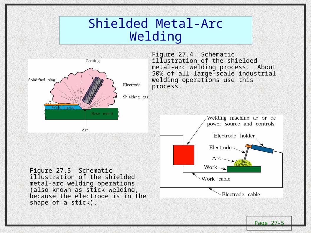
Shielded Metal-Arc Welding
Figure 27.4 Schematic illustration of the shielded metal-arc welding process. About 50% of all large-scale industrial welding operations use this process.
Figure 27.5 Schematic illustration of the shielded metal-arc welding operations (also known as stick welding, because the electrode is in the shape of a stick).
Page 27-6
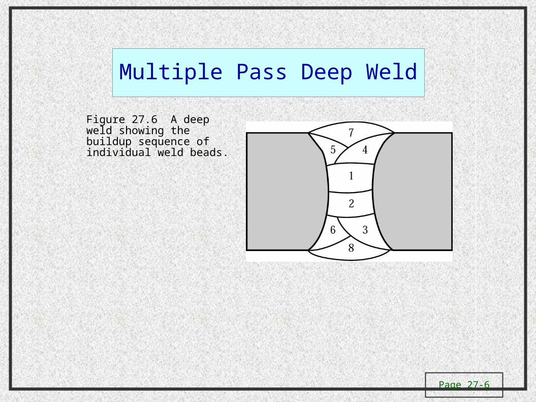
Multiple Pass Deep Weld
Figure 27.6 A deep weld showing the buildup sequence of individual weld beads.
Page 27-7
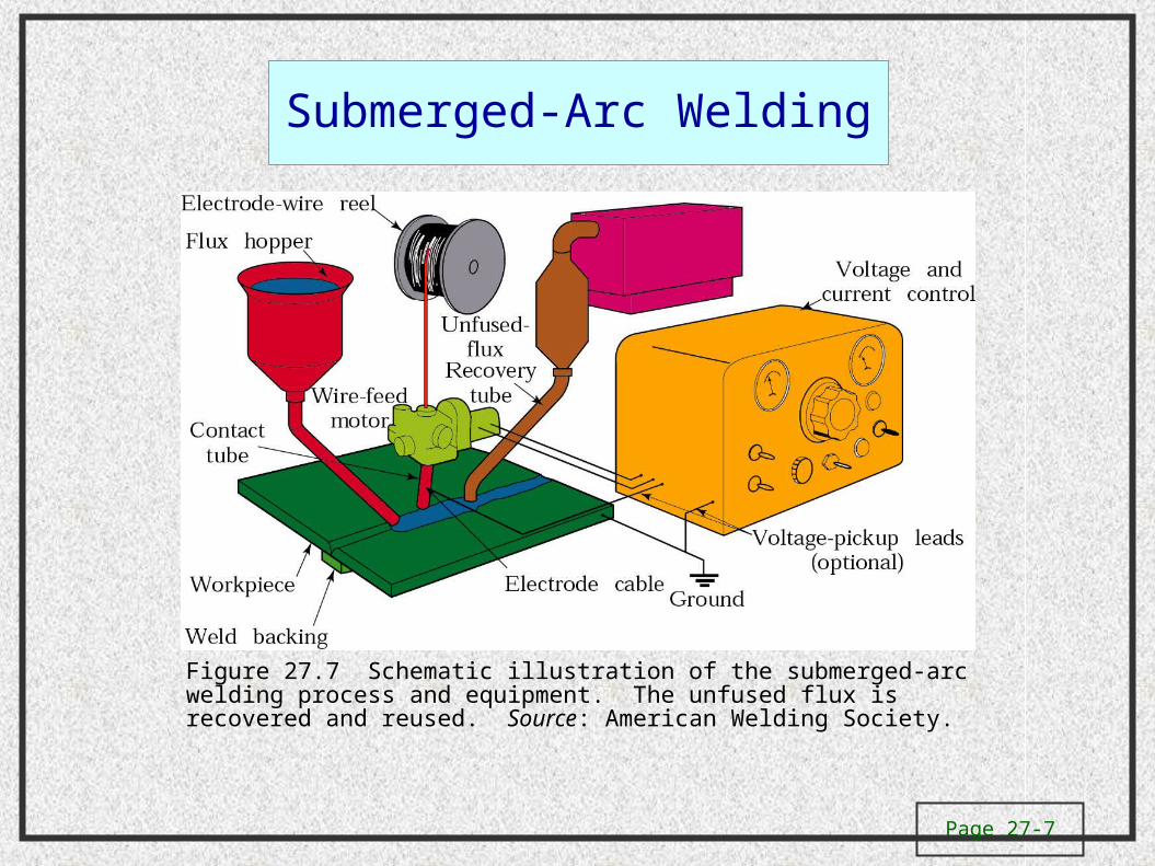
Submerged-Arc Welding
Figure 27.7 Schematic illustration of the submerged-arc welding process and equipment. The unfused flux is recovered and reused. Source: American Welding Society.
Page 27-8
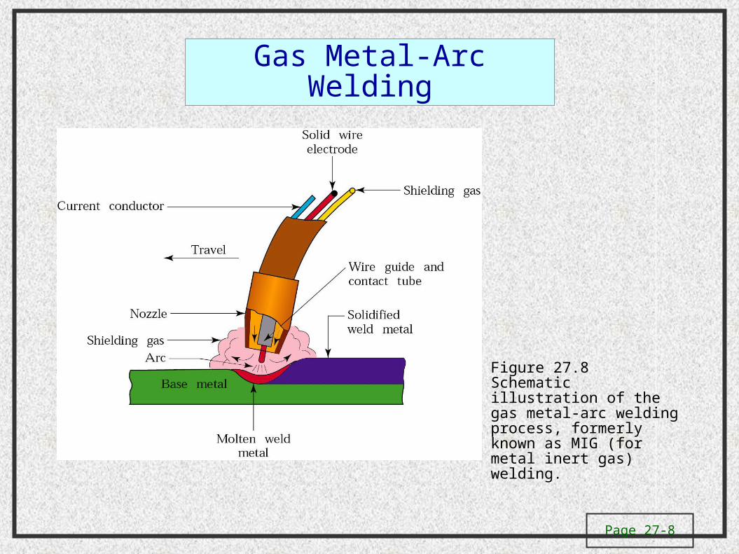
Gas Metal-Arc Welding
Figure 27.8 Schematic illustration of the gas metal-arc welding process, formerly known as MIG (for metal inert gas) welding.
Page 27-9
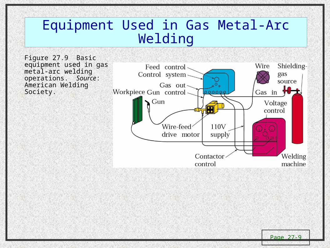
Equipment Used in Gas Metal-Arc Welding
Figure 27.9 Basic equipment used in gas metal-arc welding operations. Source: American Welding Society.
Page 27-10
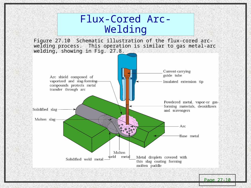
Flux-Cored Arc-Welding
Figure 27.10 Schematic illustration of the flux-cored arc-welding process. This operation is similar to gas metal-arc welding, showing in Fig. 27.8.
Page 27-11
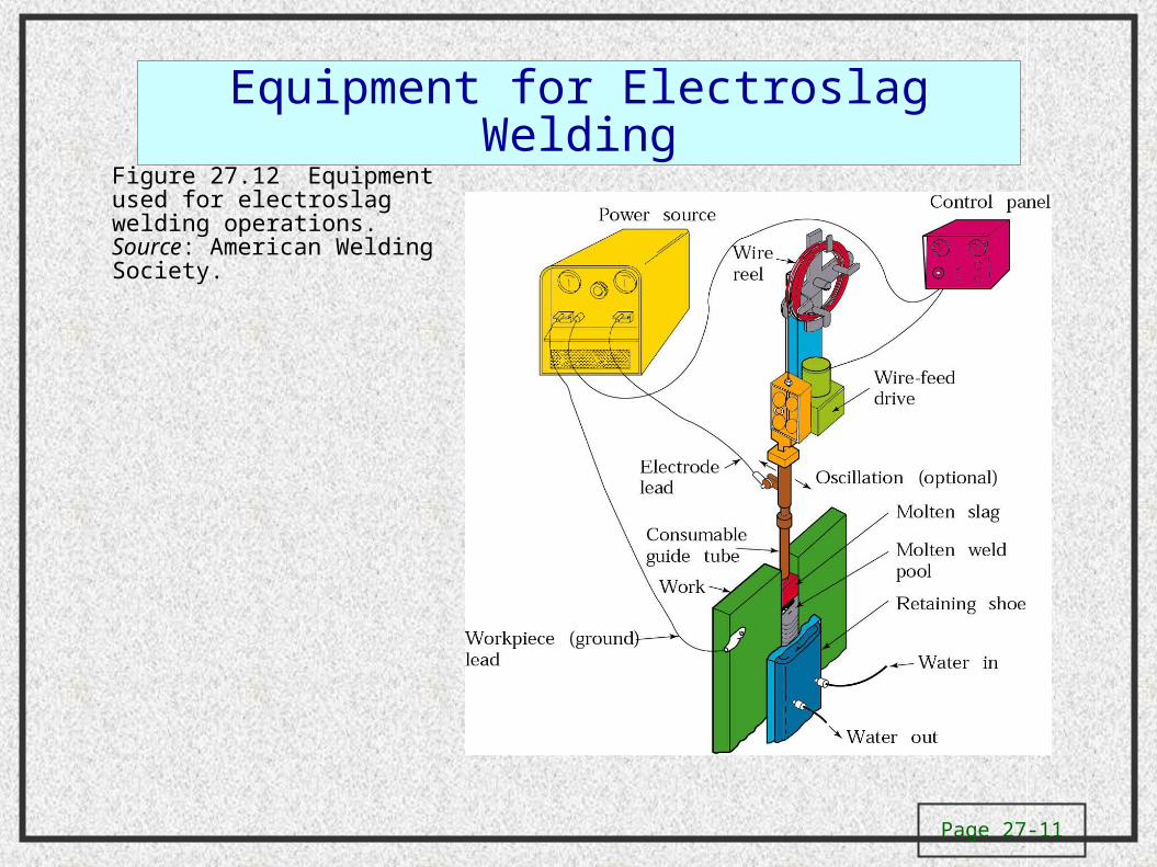
Equipment for Electroslag Welding
Figure 27.12 Equipment used for electroslag welding operations. Source: American Welding Society.
Page 27-12
Designations for Mild Steel Coated Electrodes
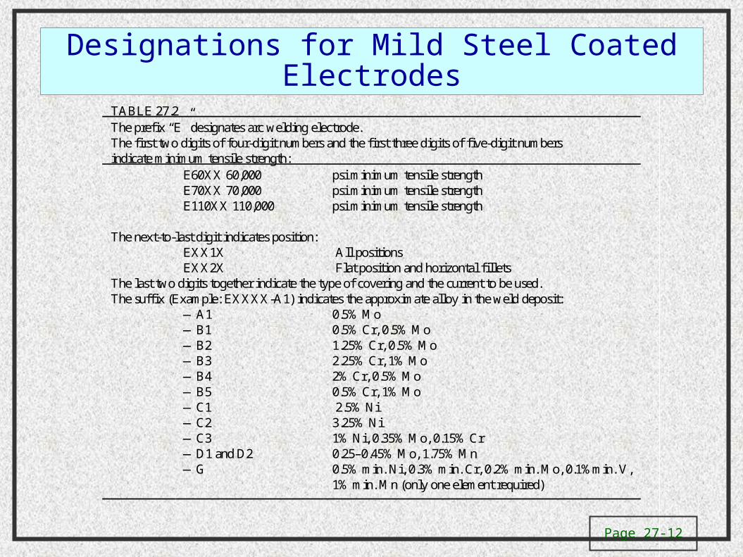
TABLE 27.2The prefix “E” designates arc welding electrode.The first two digits of four-digit numbers and the first three digits of five-digit numbersindicate minimum tensile strength:
E60XX 60,000 psi minimum tensile strengthE70XX 70,000 psi minimum tensile strengthE110XX 110,000 psi minimum tensile strength
The next-to-last digit indicates position:EXX1X All positionsEXX2X Flat position and horizontal fillets
The last two digits together indicate the type of covering and the current to be used.The suffix (Example: EXXXX-A1) indicates the approximate alloy in the weld deposit:
—A1 0.5% Mo—B1 0.5% Cr, 0.5% Mo—B2 1.25% Cr, 0.5% Mo—B3 2.25% Cr, 1% Mo—B4 2% Cr, 0.5% Mo—B5 0.5% Cr, 1% Mo—C1 2.5% Ni—C2 3.25% Ni—C3 1% Ni, 0.35% Mo, 0.15% Cr—D1 and D2 0.25–0.45% Mo, 1.75% Mn—G 0.5% min. Ni, 0.3% min. Cr, 0.2% min. Mo, 0.1%min. V,
1% min. Mn (only one element required)
Page 27-13
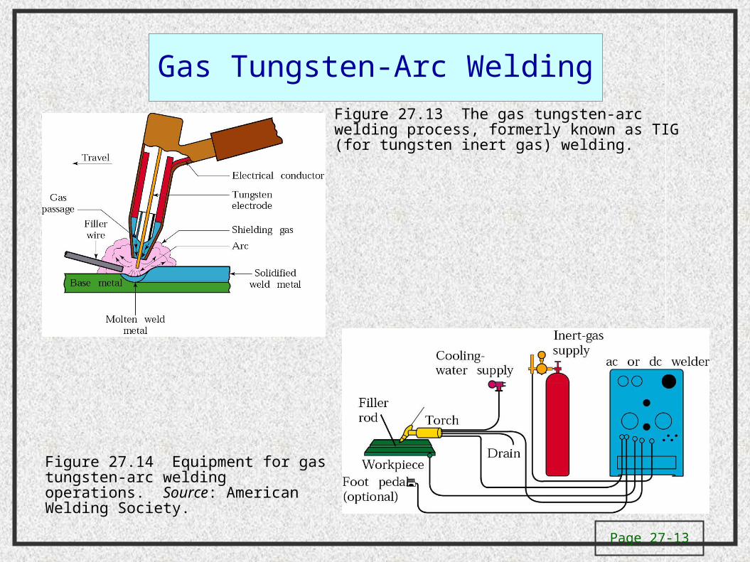
Gas Tungsten-Arc Welding
Figure 27.13 The gas tungsten-arc welding process, formerly known as TIG (for tungsten inert gas) welding.
Figure 27.14 Equipment for gas tungsten-arc welding operations. Source: American Welding Society.
Page 27-14
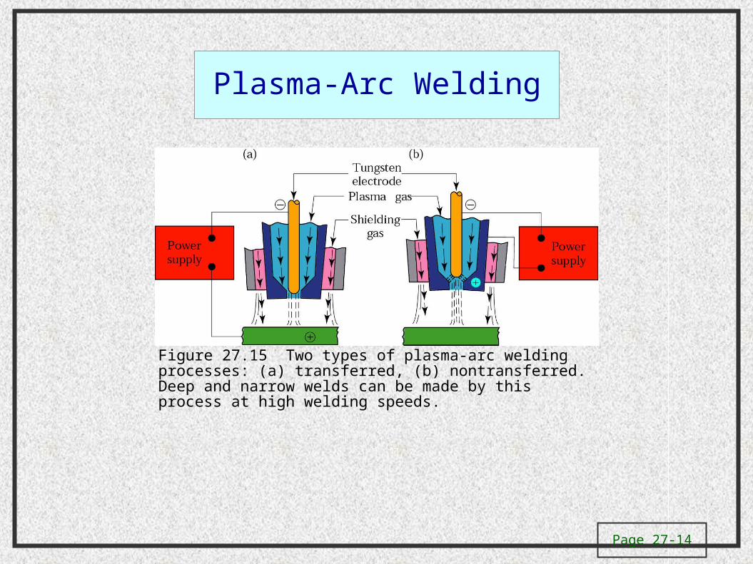
Plasma-Arc Welding
Figure 27.15 Two types of plasma-arc welding processes: (a) transferred, (b) nontransferred. Deep and narrow welds can be made by this process at high welding speeds.
Page 27-15
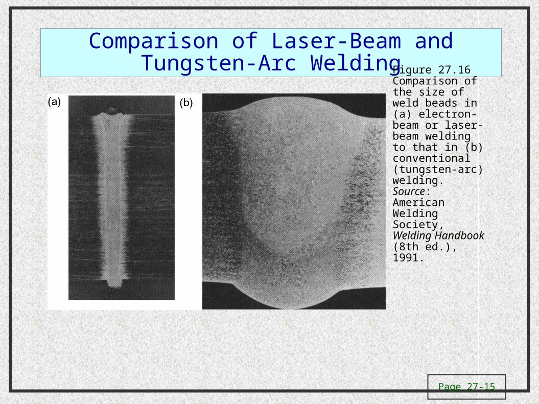
Comparison of Laser-Beam and Tungsten-Arc Welding
Figure 27.16 Comparison of the size of weld beads in (a) electron-beam or laser-beam welding to that in (b) conventional (tungsten-arc) welding. Source: American Welding Society, Welding Handbook (8th ed.), 1991.
Page 27-16
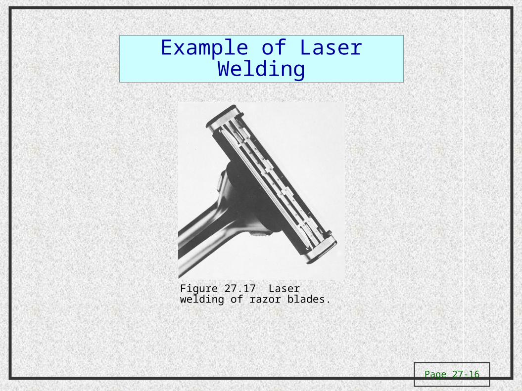
Example of Laser Welding
Figure 27.17 Laser welding of razor blades.
Page 27-17
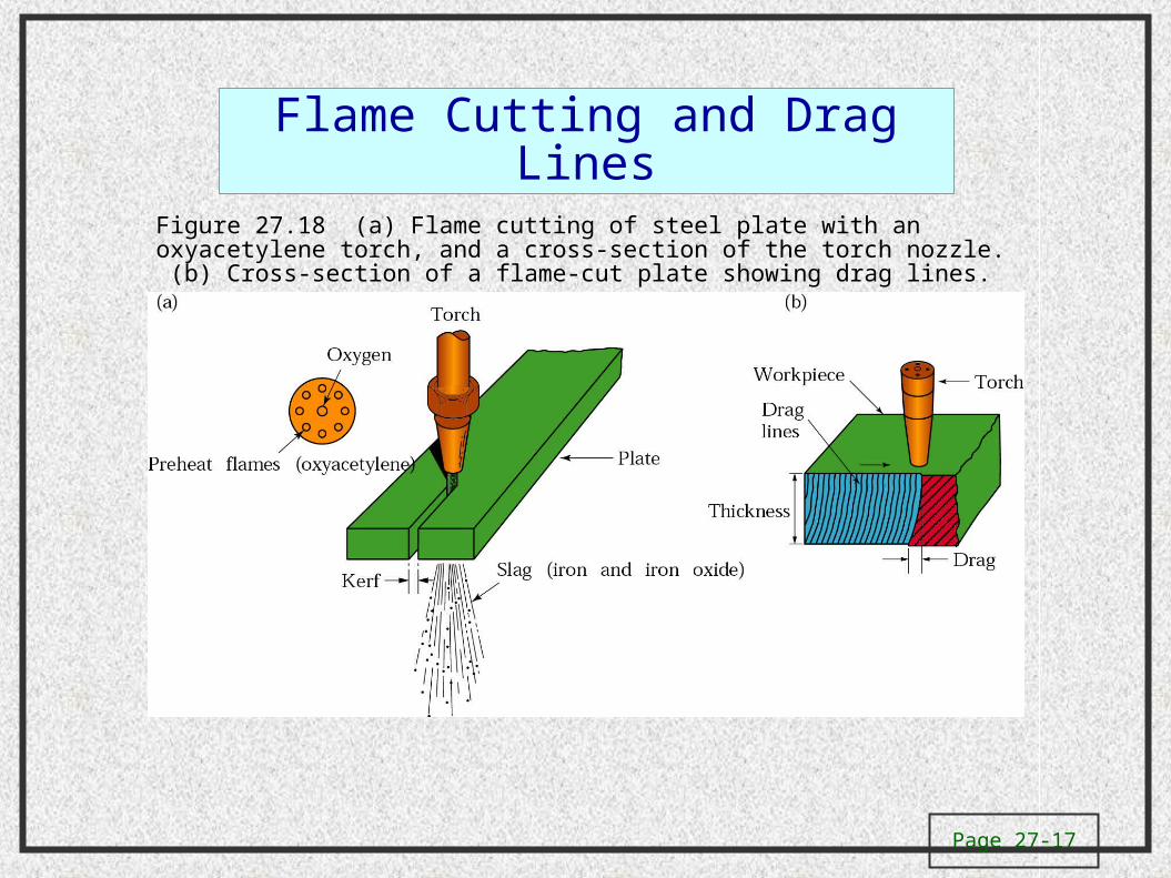
Flame Cutting and Drag Lines
Figure 27.18 (a) Flame cutting of steel plate with an oxyacetylene torch, and a cross-section of the torch nozzle. (b) Cross-section of a flame-cut plate showing drag lines.
Page 27-18
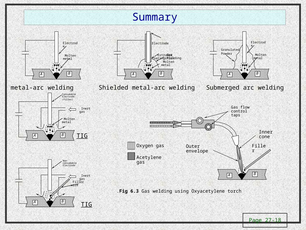
Summary
A B
Electrode
Molten metal
A B
Electrode
Extruded coating flux
Molten metal
Gas shielding
A B
Electrode
Molten metal
Granulated Powder
A B
Consumable Electrode(filler)
Molten metal
Inert gas
A B
Non-consumable Electrode
Filler wire
Inert gas
TIG
TIG
Submerged arc welding Shielded metal-arc welding metal-arc welding
Filler
A B
Oxygen gas
Acetylene gas
Gas flow control taps
Inner cone
Outer envelope
Fig 6.3 Gas welding using Oxyacetylene torch.
Page 27-19
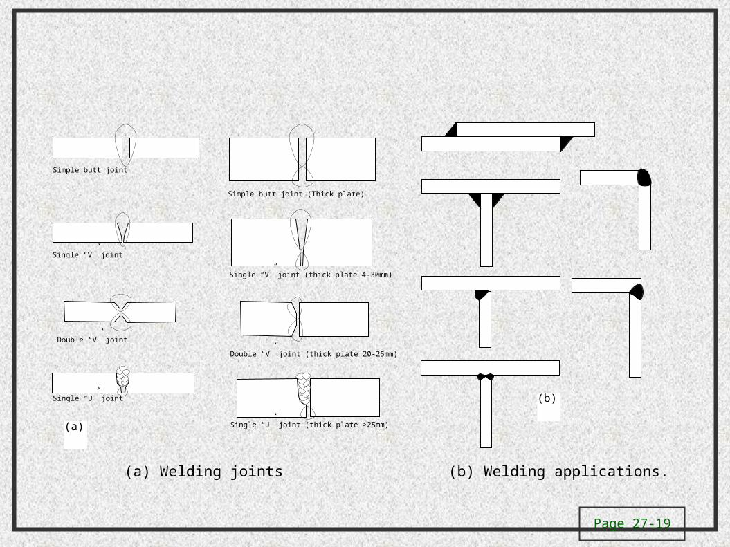
Simple butt joint
Simple butt joint (Thick plate)
Single “V” joint
Single “V” joint (thick plate 4-30mm)
Double “V” joint
Double “V” joint (thick plate 20-25mm)
Single “U” joint
Single “J” joint (thick plate >25mm)(a)
(b)
(a) Welding joints (b) Welding applications.
Page 27-20
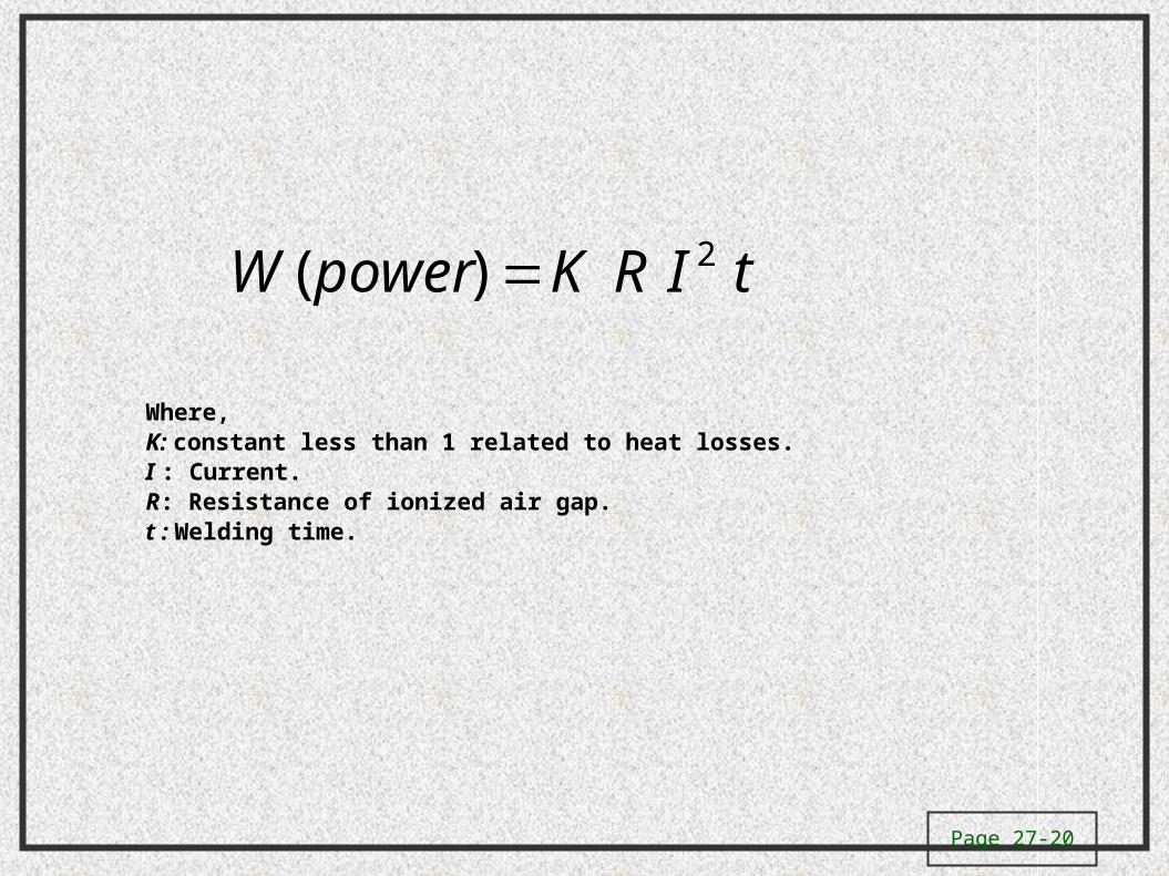
tIRKpowerW 2)(
Where,K: constant less than 1 related to heat losses.I : Current. R: Resistance of ionized air gap.t : Welding time.


