SECTION 2 – STANDARD SPECIFICATIONS 00950 – MEASUREMENT AND PAYMENT
1.1 TRENCHING, BACKFILLING AND COMPACTION OF UTILITIES 00950-1 1.2 WATER 00950-6 1.3 SEWER 00950-15
02275-TRENCHING, BACKFILLING AND COMPACTION OF UTILITIES TRENCHING, BACKFILLING AND COMPACTION OF UTILITIES REVISION SUMMARY SHEET
PART 1 - GENERAL 1.1 GENERAL 02275-1 1.2 RELATED DOCUMENTS 02275-1 1.3 SUMMARY 02275-2 1.4 DEFININITIONS 02275-2 1.5 SUBMITTALS 02275-3 1.6 QUALITY ASSURANCE 02275-4 1.7 QUALITY STANDARDS 02275-4 1.8 TESTING SERVICES 02275-6 1.9 PROJECT CONDITIONS 02275-6
1.10 LOCATING SERVICES 02275-6 1.11 COORDINATION 02275-7 1.12 PUBLIC CONVENIENCE 02275-7 1.13 EROSION AND SEDIMENTATION CONTROL AND NPDES
MONITORING, CONTROLS, AND LIMITATIONS FOR PERMITTED DISCHARGES
02275-7
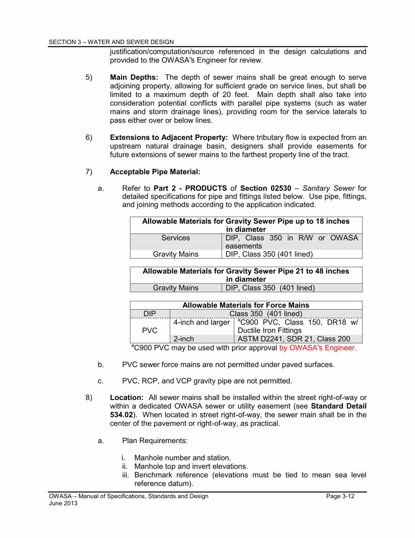
PART 2-PRODUCTS 2.1 SOIL, BEDDING, AND BACKFILL 02275-10 2.2 MISCELLANEOUS 02275-12
PART 3-EXECUTION 3.1 PREPARATION 02275-14 3.2 TRENCH EXCAVATION 02275-20 3.3 BEDDING 02275-28 3.4 BACKFILLING (MATERIALS AND METHODS) 02275-29 3.5 COMPACTION/DENSITY 02275-31 3.6 SERVICE CUTS, DIRECTION BORED OR PUNCHED SERVICE 02275-34 3.7 PAVEMENT REPAIR AND REPLACEMENT 02275-34 3.8 BLASTING 02275-35 3.9 HIGHWAY CROSSING 02275-39
3.10 RAILROAD CROSSING/TRACKS 02275-39 3.11 UNDERGROUND RIVER OR CREEK CROSSING 02275-40 3.12 SURFACE WATER CROSSINGS 02275-41 3.13 CONCRETE COLLARS ON SEWER MAINS 02275-41
OWASA – Manual of Specifications, Standards and Design Table of Contents June 2013 Page 2
3.14 CLEANUP AND RESTORATION OF SITE 02275-41 3.15 SEEDING AND GROUNDCOVER 02275-42 3.16 MISCELLANEOUS 02275-42
02510 – WATER DISTRIBUTION WATER DISTRIBUTION REVISION SUMMARY SHEET
PART 1 - GENERAL 1.1 RELATED DOCUMENTS 02510-1 1.2 SUMMARY 02510-1 1.3 DEFINITIONS 02510-1 1.4 SUBMITTALS 02510-2 1.5 QUALITY ASSURANCE 02510-2 1.6 QUALITY STANDARDS 02510-3 1.7 PRODUCT DELIVERY, STORAGE AND HANDLING 02510-4 1.8 PRODUCT SUBSTITUTIONS 02510-5 1.9 PRODUCT CONDITIONS 02510-5
PART 2 – PRODUCTS 2.1 PIPE AND FITTINGS 02510-7 2.2 VALVES AND FIRE HYDRANTS 02510-15 2.3 MISCELLANEOUS APPURTENANCES 02510-21
PART 3-EXECUTION 3.1 PIPE AND FITTINGS 02510-30 3.2 VALVES AND HYDRANTS 02510-40 3.3 MISCELLANEOUS APPURTENANCES 02510-43 3.4 TESTING AND DISINFECTION 02510-47 3.5 FINAL ACCEPTANCE 02510-56
02520 – RECLAIMED WATER DISTRIBUTION PART 1 - GENERAL
1.10 SEPARATIONS OF RECLAIMED WATER MAINS AND SANITARY AND/OR COMBINED SEWERS
02520-2
1.11 COORDINATION 02520-2 1.12 CROSS CONNECTION CONTROL 02520-2
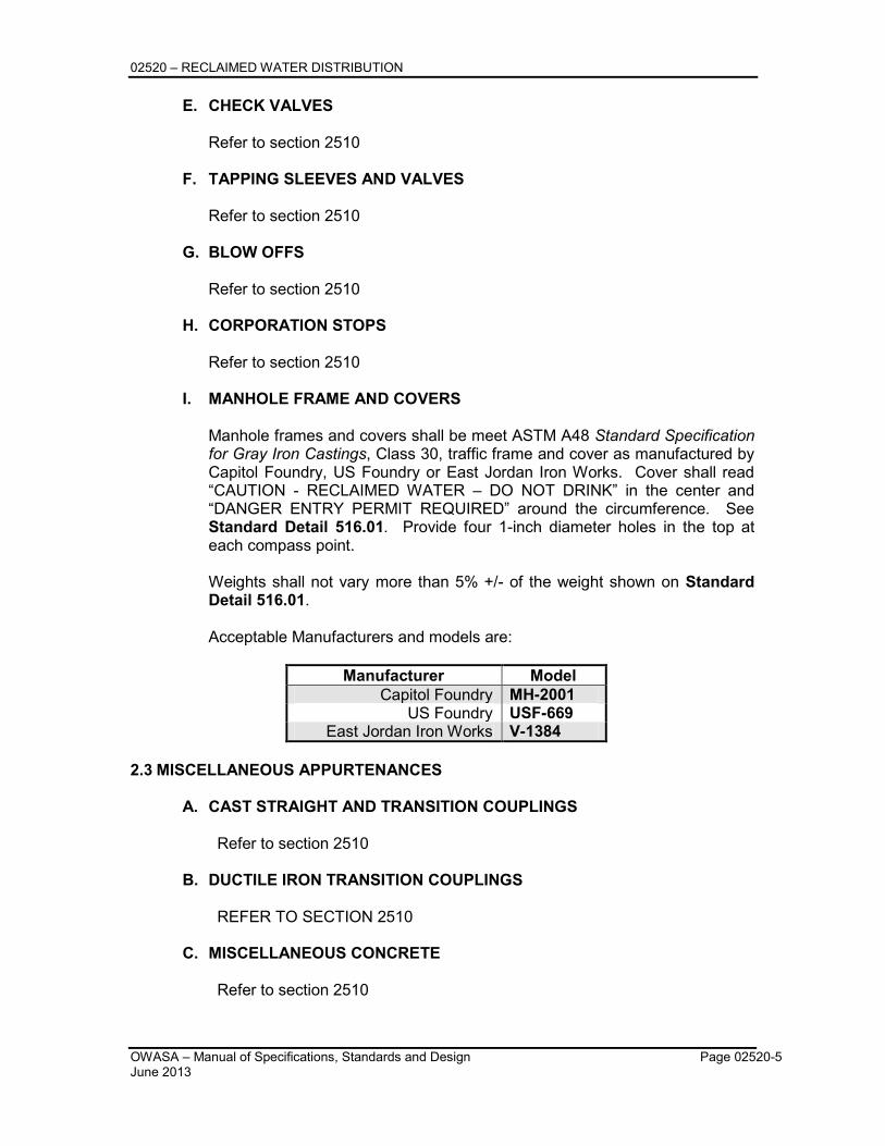
PART 2 – PRODUCTS 2.1 PIPE, FITTINGS AND IDENTIFICATION 02520-2 2.2 VALVES AND FIRE HYDRANTS 02520-4 2.3 MISCELLANEOUS APPURENANCES 02520-5
PART 3 – EXECUTION 3.1 PIPE AND FITTINGS 02520-6 3.2 UTILITY PROTECTION 02520-7 3.3 SURFACE GROUND WATER IN TRENCHES / PIPE 02520-7 3.4 ABANDONING OF AN EXISTING WATER SERVICE/ LINES 02520-7 3.5 STEEL ENCASEMENT PIPE – DRY BORING AND JACKING OR
OPEN CUT 02580-7
3.6 HORIZONTAL DIRECTIONAL DRILLING OF HDPE WATER PIPE 02520-7 3.7 PVC PIPE FOR RECLAIMED WATER MAIN 02520-8
OWASA – Manual of Specifications, Standards and Design Table of Contents June 2013 Page 3
3.8 RECLAIMED GATE VALVES 02520-8 3.9 VALVES 16 INCHES AND LARGER (GATE OR BUTTERFLY VALVES) 02520-8
3.10 TAPPING SLEEVES AND VALVES 02520-8 3.11 AIR / VACUUM RELEASE VALVES 02520-8 3.12 MISCELLANEOUS APPURTENANCES 02520-8 3.13 RESTRAINTS 02520-9 3.14 VAULT CONSTRUCTION 02520-9 3.15 MANHOLE INSTALLATIONS 02520-9 3.16 CONNECTION TO EXISTING RECLAIMED MAINS 02520-9
PART 4 – TESTING 4.1 TESTING 02520-10 4.2 ORDER OF OPERATIONS 02520-11 4.3 FINAL ACCEPTANCE 02520-11
PART 2 – PRODUCTS 2.1 PIPE AND FITTINGS 02530-8 2.2 MISCELLANEOUS APPURTENANCES AND MATERIAL 02530-12
PART 3 - EXECUTION 3.1 PIPE AND FITTINGS 02530-19 3.2 TUNNELING METHOD 02530-22 3.3 MANHOLE CONSTRUCTION 02530-24 3.4 ABANDONING SEWER LINES & MANHOLES 02530-25 3.5 BYPASS PUMPING 02530-26 3.6 SERVICE CONNECTIONS 02530-28 3.7 CONCRETE ENCASEMENTS 02530-29 3.8 USE OF SLOPE ANCHORS ON STEEP LINES 02530-30 3.9 TESTING 02530-30
3.10 PUMP STATIONS AND FORCE MAINS 02530-37 3.11 PIPE DESIGN LIFE 02530-42 3.12 CLEANUP AND RESTORATION OF SITE 02530-42
OWASA – Manual of Specifications, Standards and Design Table of Contents June 2013 Page 4
SECTION 3 – MODULES 1 & 2: WATER AND SEWER DESIGN
SANITARY SEWER REVISION SUMMARY SHEET 1.1 GENERAL 3-1
A. SPECIFICATIONS AND DESIGN MANUAL 3-1 B. PROJECT OVERVIEW REPORT REQUIREMENTS 3-1 C. PERMITS 3-2 D. PLAN REVIEW AND OBSERVATION FEES 3-2
1.2 WATER SYSTEM DESIGN STANDARDS 3-2 A. DISTRIBUTION SYSTEM 3-2
1.3 GRAVITY COLLECTION SYSTEM DESIGN STANDARDS 3-10 A. GENERAL 3-10 B. DEFINITIONS 3-10 C. COLLECTION SYSTEM DESIGN 3-11 D. DESIGN – MANHOLES 3-16 E. SEWERS IN RELATION TO STREAMS AND OTHER BODIES 3-19 F. PROTECTION OF POTABLE WATER SUPPLIES AND
STORM SEWERS 3-22
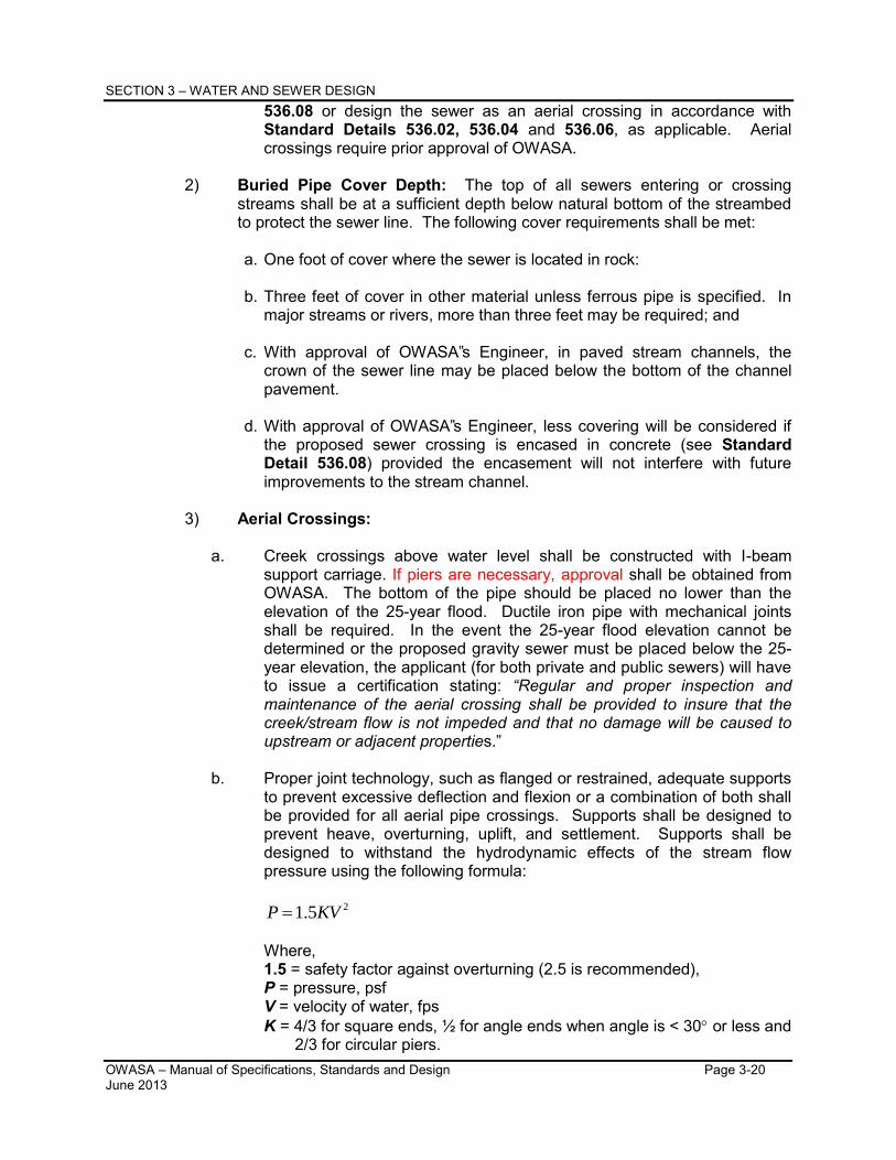
G. PUMP STATION 3-23 SECTION 4 – PROCEDURES FOR APPROVAL OF WATER AND/OR SEWER EXTENSTION PROJECTS
PROCEDURES FOR APPROVAL OF WATER AND/OR SEWER EXTENSION PROJECTS REVISION SUMMARY SHEET
1.1. INTRODUCTION 4-1 1.2 PLAN REQUIREMENTS 4-2
A. GENERAL 4-2 B. WATER LINE EXTENTION PLANS 4-4 C. SEWER LINE EXTENSION PLANS 4-4
1.3 DESIGN AND PLAN APPROVAL 4-5 A. DISCUSS PRELIMINARY DESIGN REQUIREMENTS WITH
OWASA 4-5
B. DISCUSS AVAILABILITY FEES WITH OWASA 4-5 C. SUBMIT PRELIMINARY PROJECT PLANS TO LOCAL
PLANNING UNIT AND OWASA 4-6
D. REVIEW OF PRELIMINARY (ZONING COMPLIANCE) PLANS BY OWASA
4-6
E. PRELIMINARY DESIGN APPROVAL BY OWASA 4-6 F. SUBMIT CONSTRUCTION DRAWINGS TO OWASA 4-6 G. CONSTRUCTION DESIGN APPROVAL BY OWASA 4-7 H. SUBMIT PROJECT FACT SHEET 4-7 I. RECORDED OFF-SITE DEEDS OF EASEMENT 4-7 J. PROJECT CONSTRUCTION DRAWINGS APPROVAL 4-7 K. PROJECT DRAWINGS, APPLICATIONS, AND APPLICATION
FEES ARE SUBMITTED TO STATE REGULATORY AGENCIES BY OWASA
4-8
L NCDOT RIGHT OF WAY ENCROACHMENT 4-8 M. DESIGN APPROVAL BY STATE REGULATORY AGENCIES
(DWQ, DEH) 4-8
N. FINAL DESIGN APPROVAL BY OWASA 4-8 1.4 CONSTRUCTION 4-8
A. PRECONSTRUCTION CONFERENCE 4-8 B. BEGIN CONSTRUCTION 4-9 C. CONSTRUCTION INSPECTION 4-9 D. PRESSURE, VACUUM, AND BACTERIOLOGICAL TEST 4-10 E. PRELIMINARY FINAL INSPECTION 4-10
OWASA – Manual of Specifications, Standards and Design Table of Contents June 2013 Page 5
F. PROVISION OF CONSTRUCTION METERS BY OWASA 4-10 G. FINAL INSPECTION BY OWASA 4-10
1.5 CLOSE-OUT DOCUMENTS 4-10 A. SUBMIT ENGINEER’S CERTIFICATION OF PUBLIC WATER
LINES TO OWASA 4-10
B. SUBMIT ENGINEER’S CERTIFICATION OF PUBLIC SEWER LINES TO OWASA
4-11
C. SUBMIT RECORDED FINAL PLAT TO OWASA 4-11 D. SUBMIT 1”=100’ SCALE SITE PLAN TO OWASA 4-11 E. SUBMIT ORIGINAL RECORDED DEED OF EASEMENT TO
OWASA 4-11
F. SUBMIT LETTER OF DEDICATION TO OWASA 4-11 G. SUBMIT ASSET EVALUATION FORM TO OWASA 4-12 H. SUBMIT RECORD DRAWINGS TO OWASA FOR REVIEW 4-12 I. SUBMIT ELECTRONIC FILES TO OWASA 4-12 J. SUBMIT MANHOLE DATA SHEETS TO OWASA 4-12 K. SUBMIT OPERATION AND MAINTENANCE MANUALS TO
OWASA 4-13
L. SUBMIT LETTER OF CREDIT TO OWASA 4-13 1.6 TENTATIVE ACCEPTANCE AND BEGINNING OF ONE-YEAR
WARRANTY 4-13
1.7 PAYMENT OF FEES AND SETTING OF METERS 4-13 A. CALCULATION OF AVAILABILITY FEES BY OWASA 4-13 B. PAY AVAILABILITY FEES TO OWASA CUSTOMER SERVICE
DEPARTMENT FOR SERVICE INITIATION 4-14
C. SETTING OF WATER METERS 4-14 1.8 FINAL ACCEPTANCE 4-14
A. WARRANTY CHECKS AND REPAIRS 4-14 B. EXPIRATION OF WARRANTY 4-14 C. LETTERS OF FINAL ACCEPTANCE 4-15
OWASA – Manual of Specifications, Standards and Design Table of Details June 2013 Page 1
TABLE OF DETAILS
DetailNumber Water Details
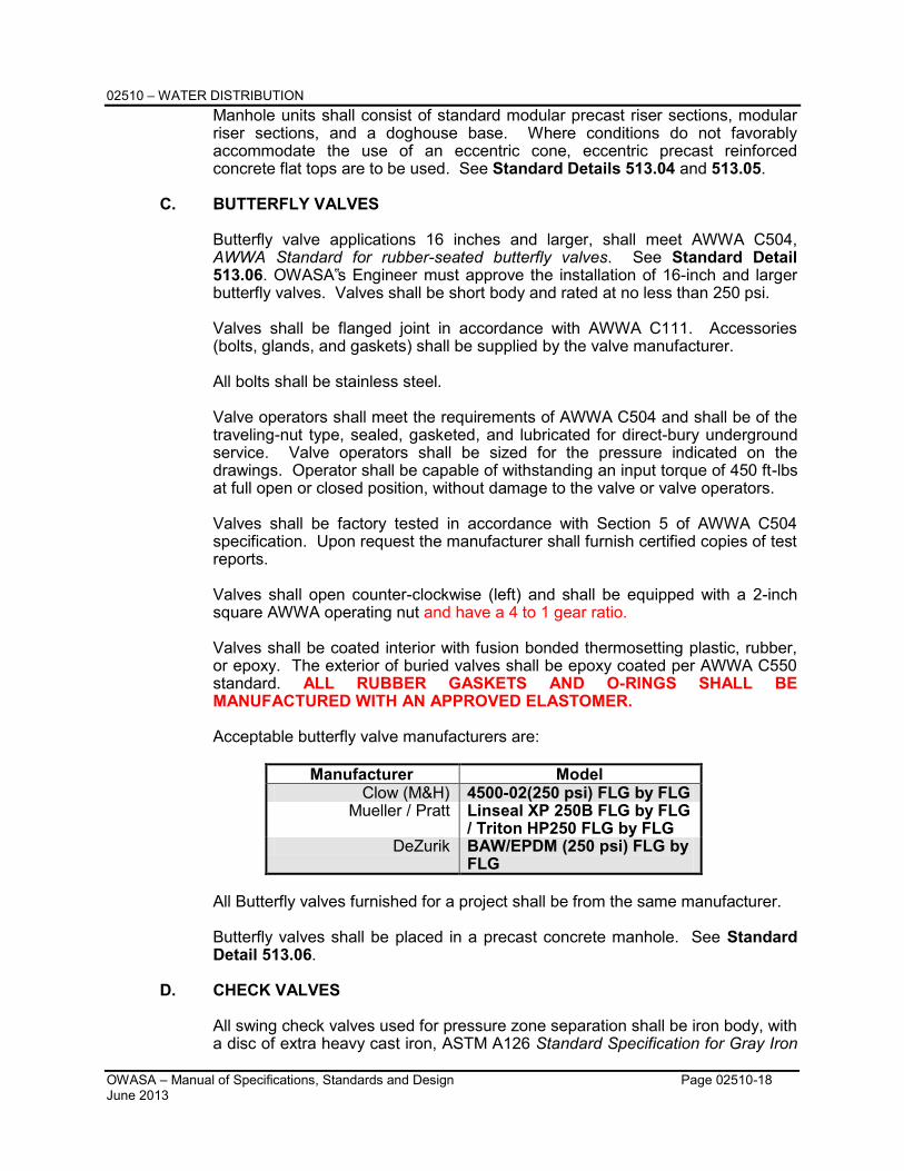
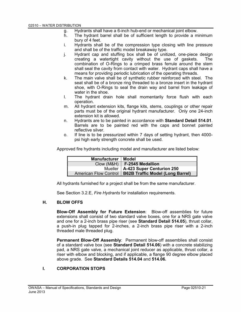
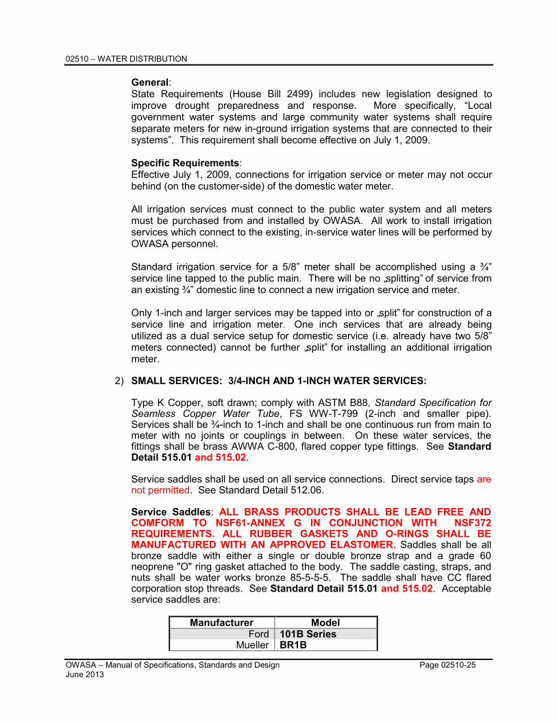
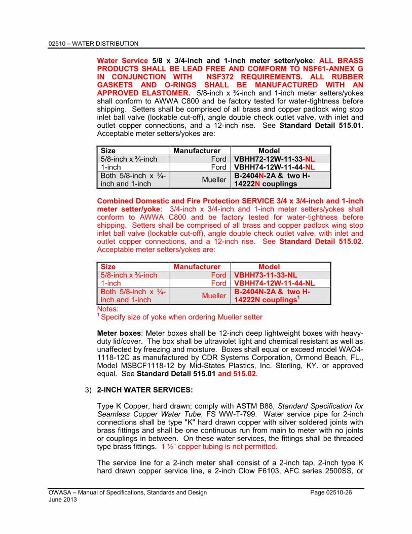
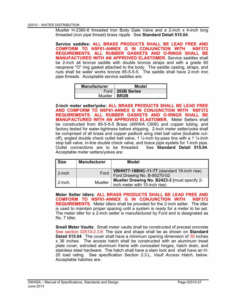
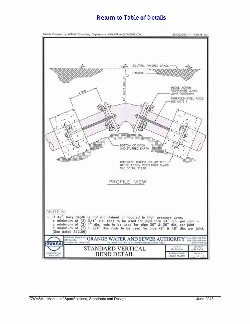
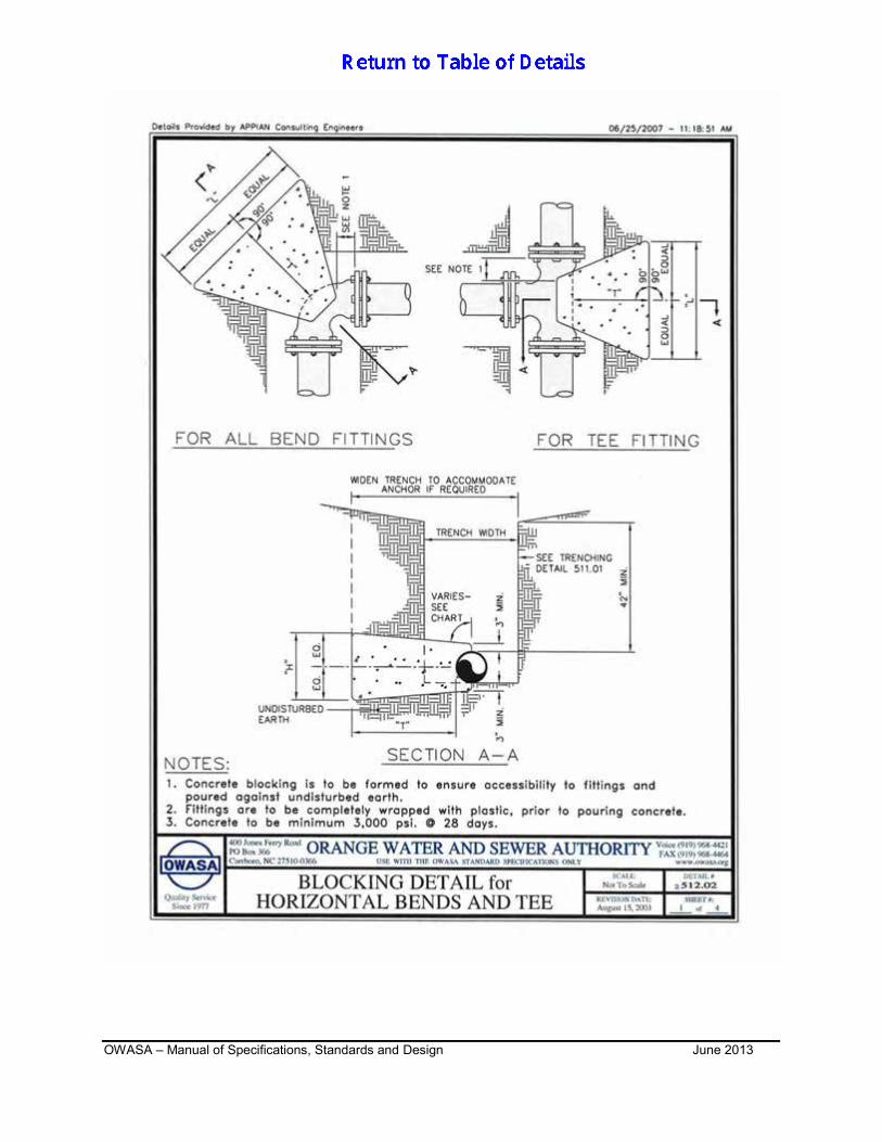
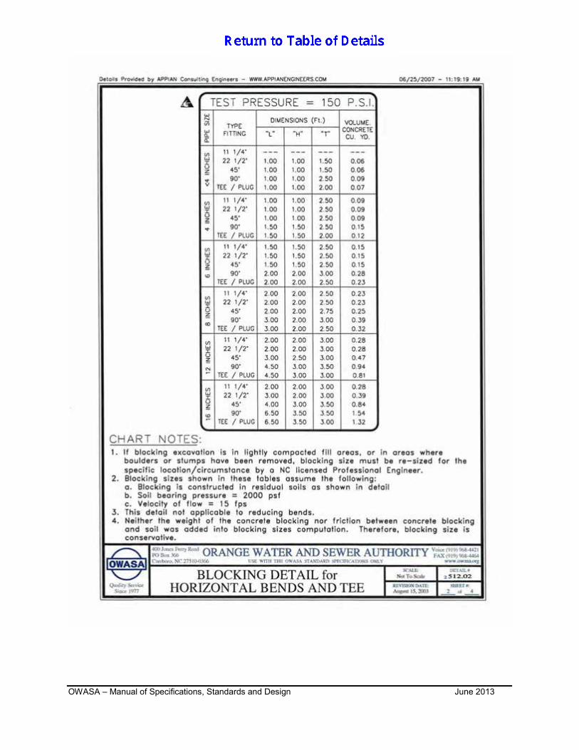
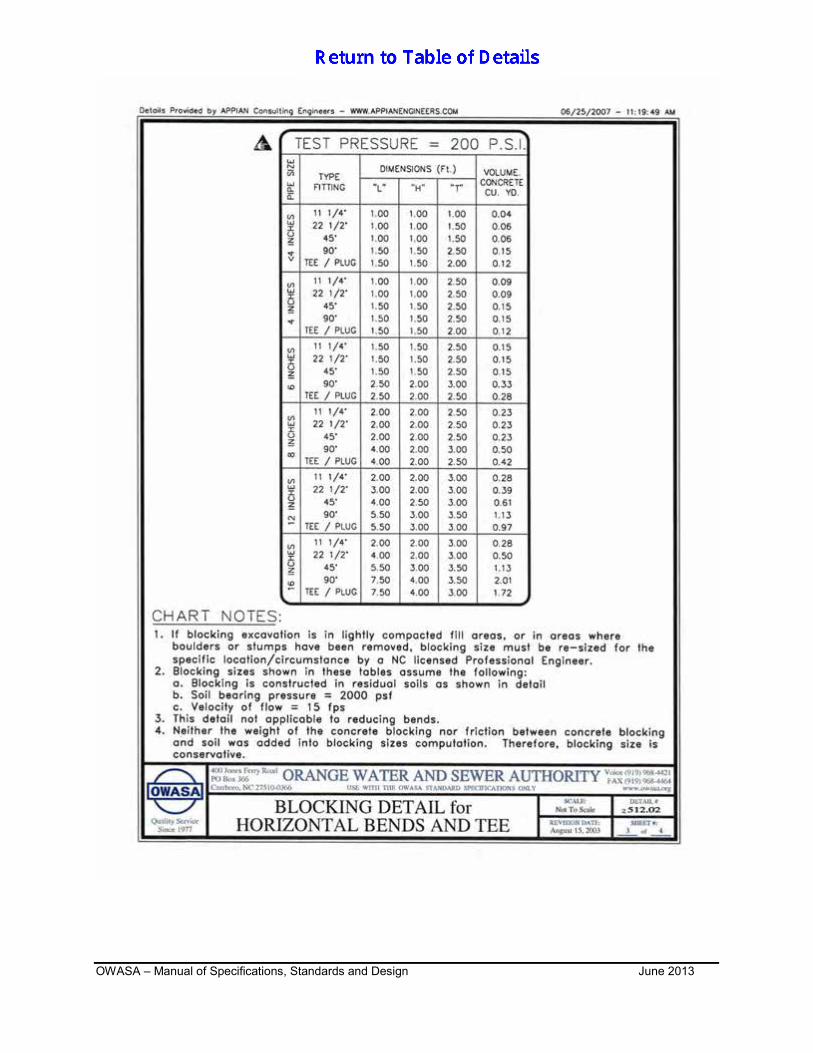
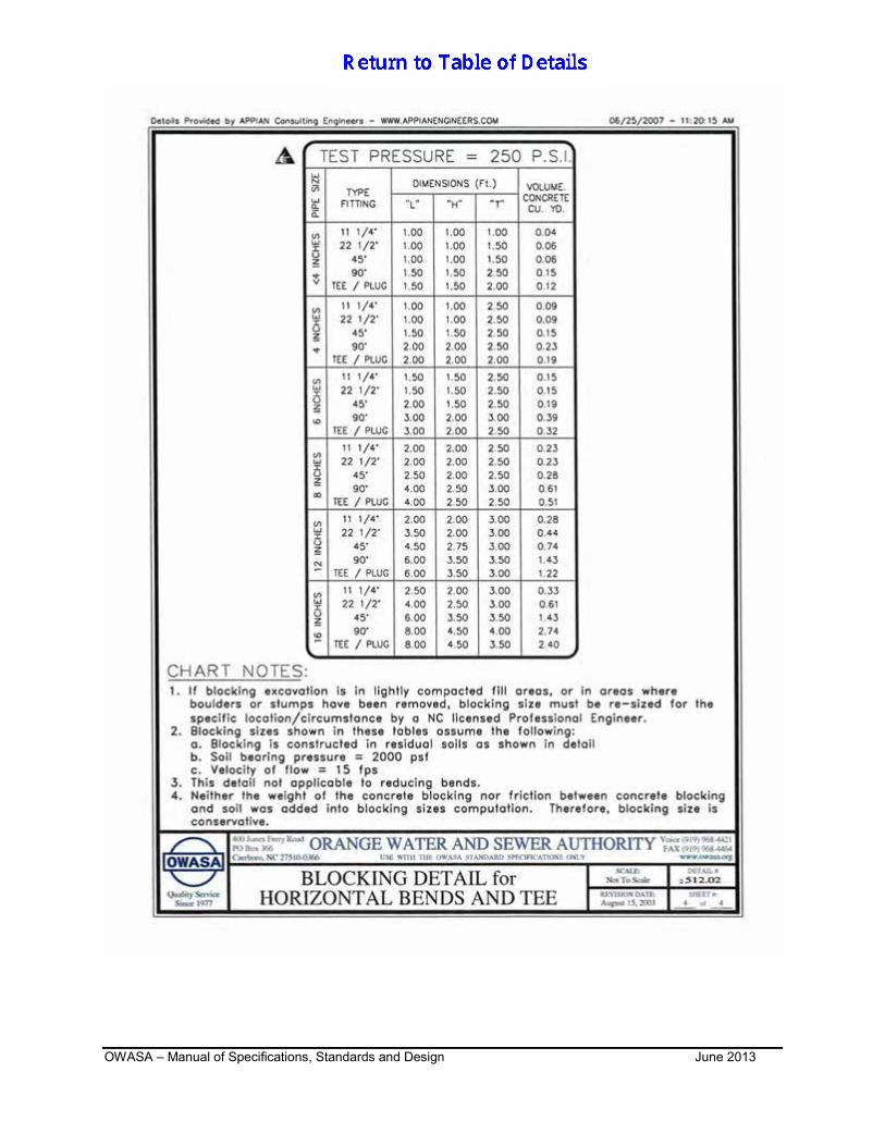
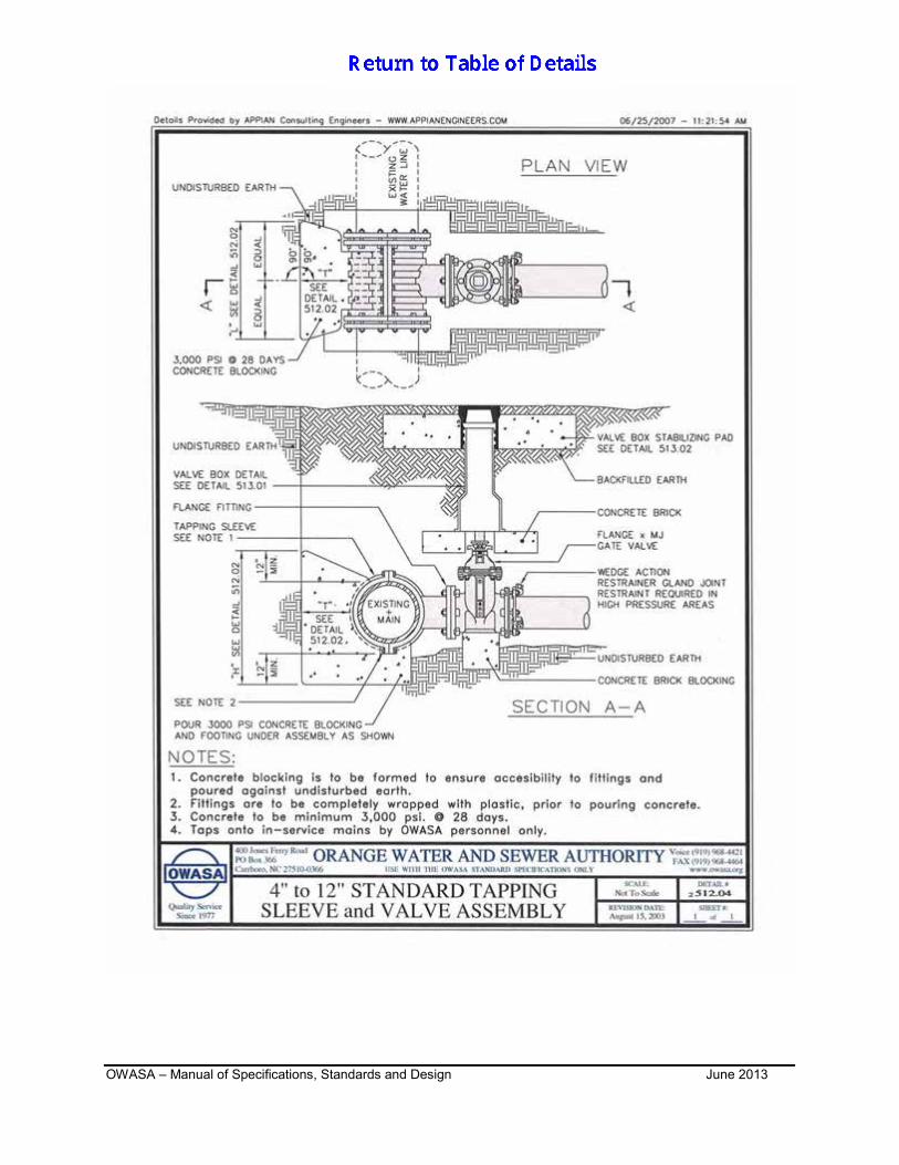
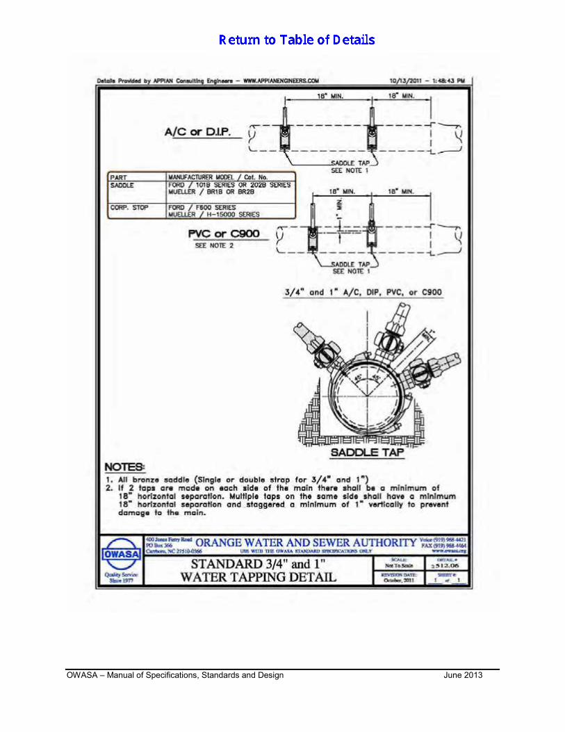
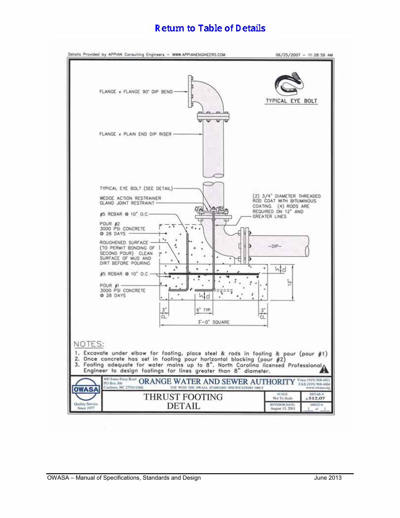
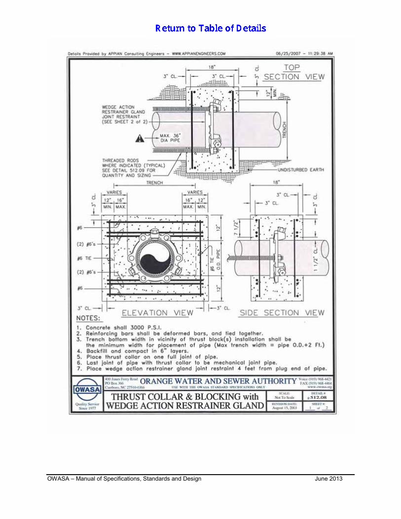
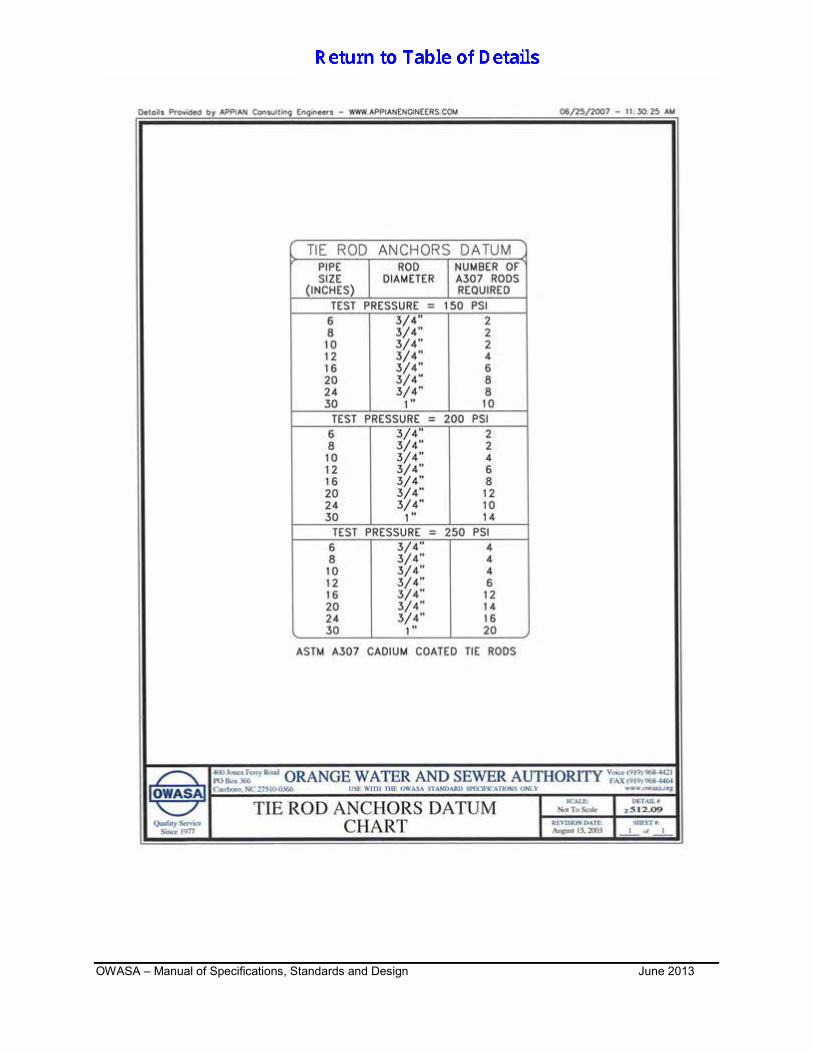
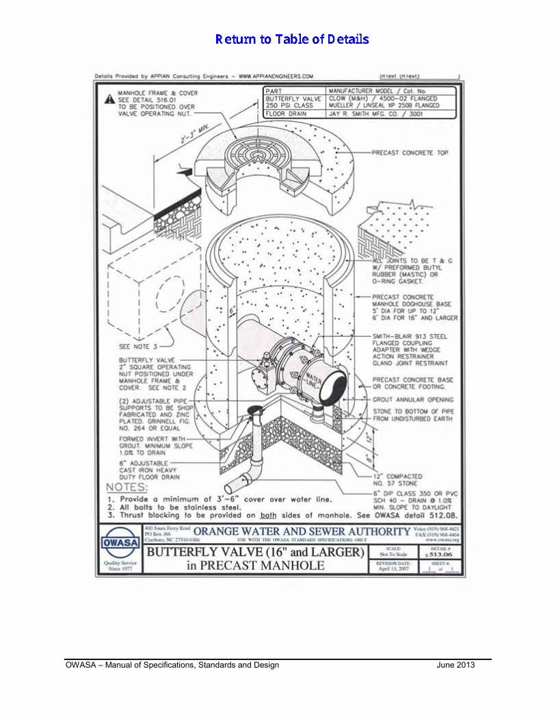
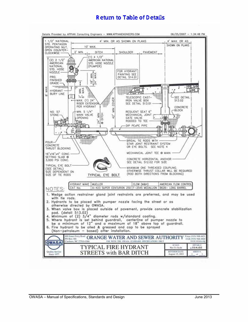
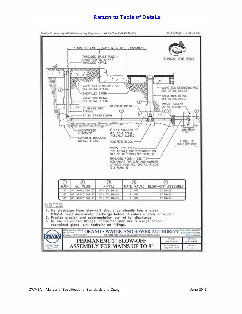
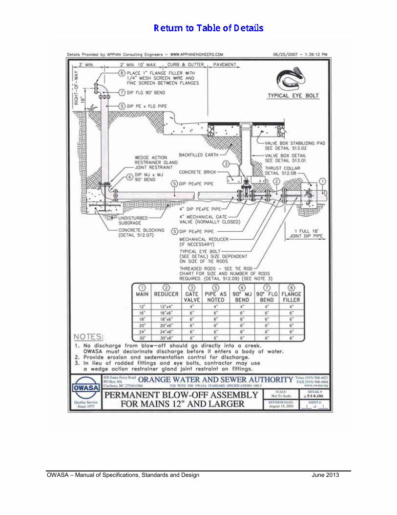
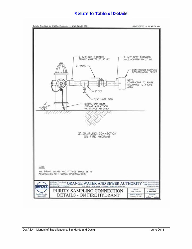
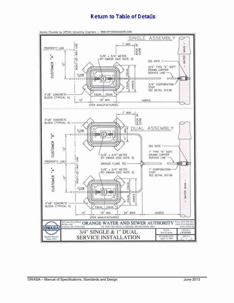
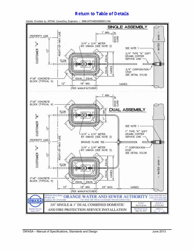
- WATER DISTRIBUTION REVISION SUMMARY SHEET 511.01 DETAIL OF ROCK EXCAVATION 512.01 STANDARD VERTICAL BEND DETAIL 512.02 BLOCKING DETAIL FOR HORIZONTAL BENDS AND TEE 512.03 BLOCKING DETAIL FOR PVC PIPE IN-LINE VALVE 512.04 4” TO 12” STANDARD TAPPING SLEEVE AND VALVE ASSEMBLY 512.05 LINE ABANDONMENT DETAIL 512.06 STANDARD ¾” AND 1” WATER TAPPING DETAIL 512.07 THRUST FOOTING DETAIL 512.08 THRUST COLLAR & BLOCKING WITH MEG-A-LUG THRUST RING 512.09 TIE ROD ANCHORS DATUM CHART 513.01 STANDARD SCREW VALVE BOX DETAIL 513.02 VALVE BOX STABILIZING PAD DETAILS 513.03 ZONE SEPARATOR DETAIL 513.04 1” AIR RELEASE VALVE & MANHOLE (PIPE 2” TO 12”) 513.05 2” AIR RELEASE VALVE & MANHOLE (PIPE 16” AND LARGER) 513.06 BUTTERFLY VALVE (16” AND LARGER) IN PRECAST MANHOLE 513.07 BLANK SHEET 513.08 GATE VALVE (16” AND LARGER) IN PRECAST MANHOLE 514.01 FIRE HYDRANT PAINTING SPECIFICATIONS 514.02 TYPICAL FIRE HYDRANT STREETS WITH BAR DITCH 514.03 TYPICAL FIRE HYDRANT STREETS WITH CURB & GUTTER 514.04 PERMANENT 2” BLOW-OFF ASSEMBLY FOR MAINS UP TO 8” 514.05 TEMPORARY 2” BLOW-OFF ASSEMBLY FOR MAINS UP TO 24” 514.06 PERMANENT BLOW-OFF ASSEMBLY FOR MAINS 12” AND LARGER 514.07 PURITY SAMPLING CONNECTION 2” BLOW OFF LINE 514.08 PURITY SAMPLING CONNECTION ON FIRE HYDRANT 514.09 PURITY SAMPLING CONNECTION AT BACKFLOW PREVENTER 515.01 ¾” SINGLE & 1” DUAL SERVICE INSTALLATION 515.02 3/4” and 1” DUAL COMBINED DOMESTIC AND FIRE PROTECTION
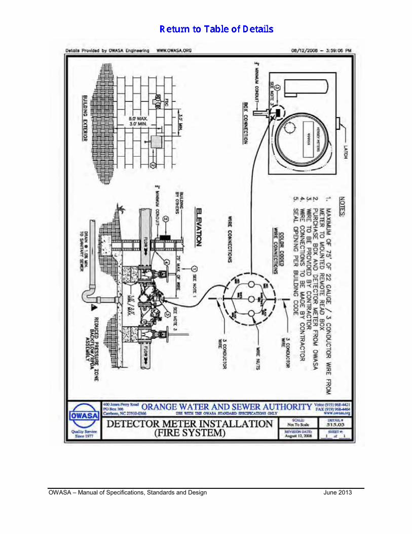
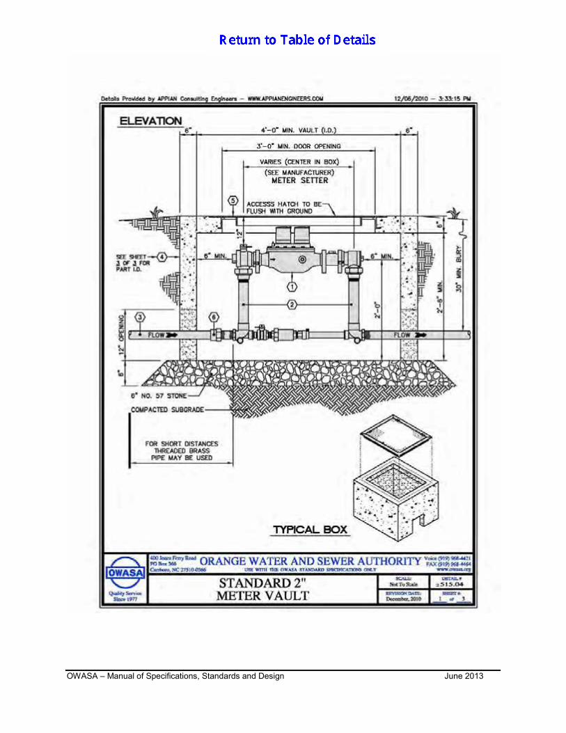
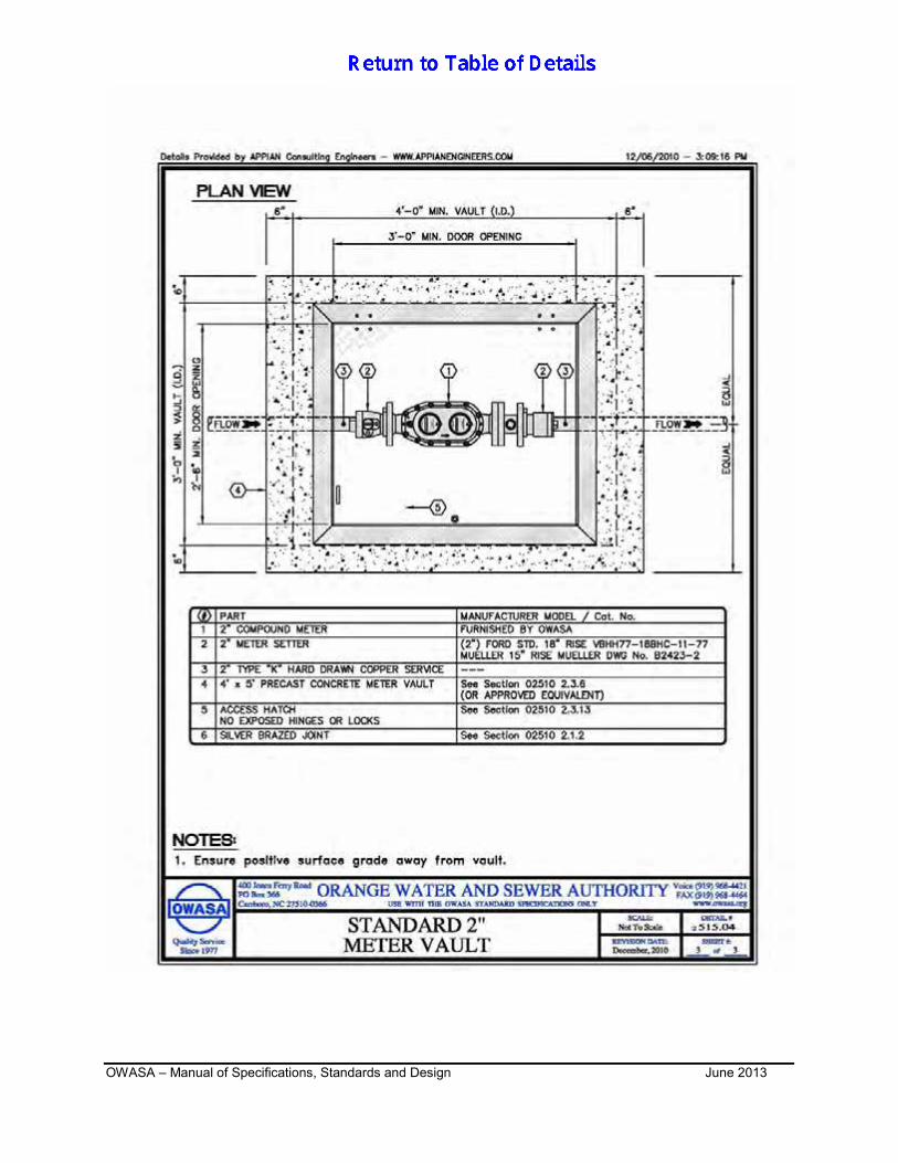
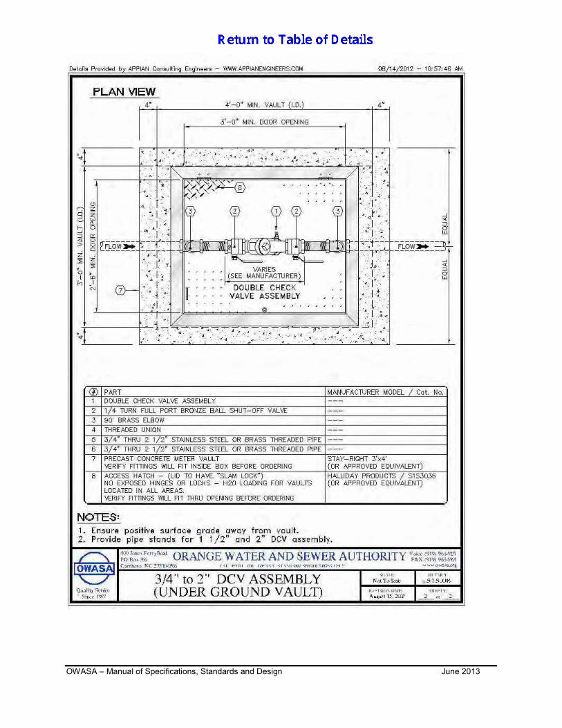
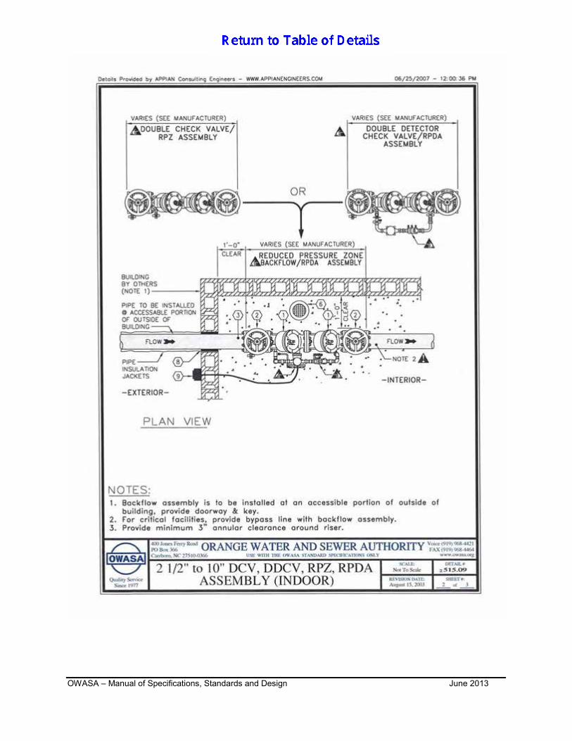
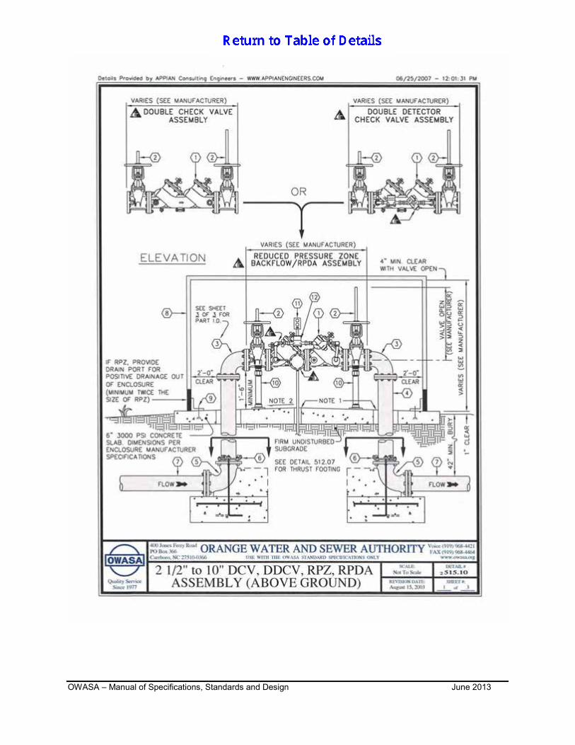
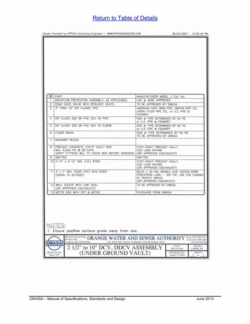
SERVICE INSTALLATION 515.03 DETECTOR METER INSTALLATION (FIRE SYSTEM) 515.04 STANDARD 2” METER VAULT 515.05 ¾” TO 2” DCV, RPZ ASSEMBLY (INDOOR) 515.06 ¾” TO 2” DCV, RPZ ASSEMBLY (ABOVE GROUND) 515.07 ¾” OR 1” DCV ASSEMBLY (ALTERNATE UNDER GROUND BOX) 515.08 ¾” OR 2” DCV ASSEMBLY (UNDER GROUND VAULT) 515.09 2 ½” TO 10” DCV, DDCV, RPZ ASSEMBLY (INDOOR) 515.10 2 ½” TO 10” DCV, DDCV, RPZ ASSEMBLY (ABOVE GROUND) 515.11 2 ½” TO 10” DCV, DDCV, RPZ ASSEMBLY (UNDERGROUND VAULT)
OWASA – Manual of Specifications, Standards and Design Table of Details June 2013 Page 2
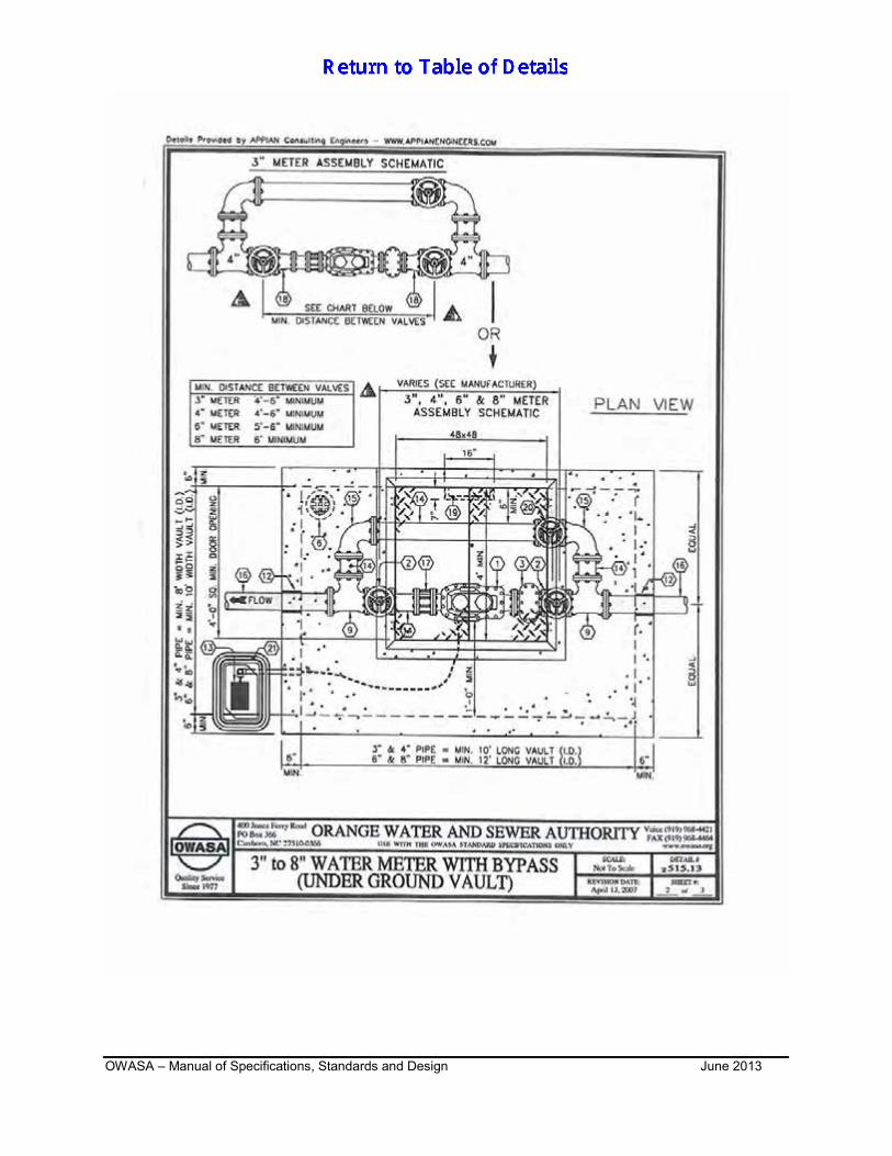
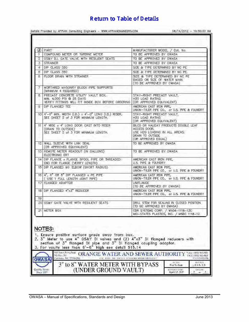
515.12 BACKFLOW PREVENTION TANKER TRUCK (AIR GAP & REDUCED PRESSURE) 515.13 3” TO 8” WATER METER WITH BYPASS (UNDERGROUND VAULT)
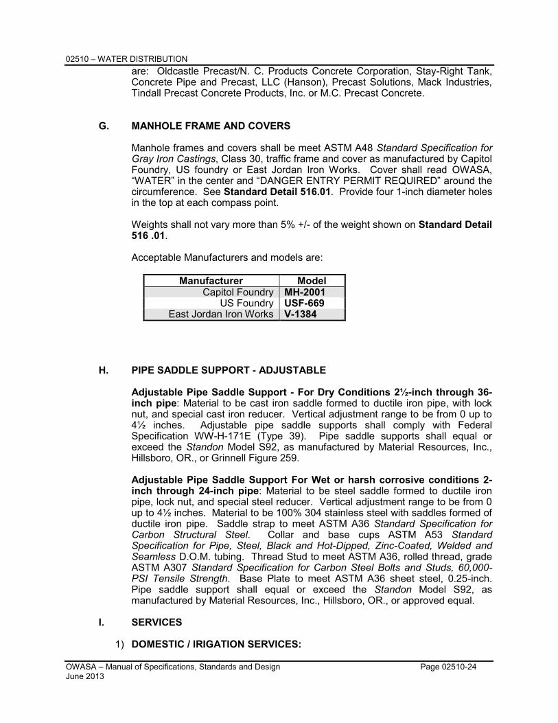
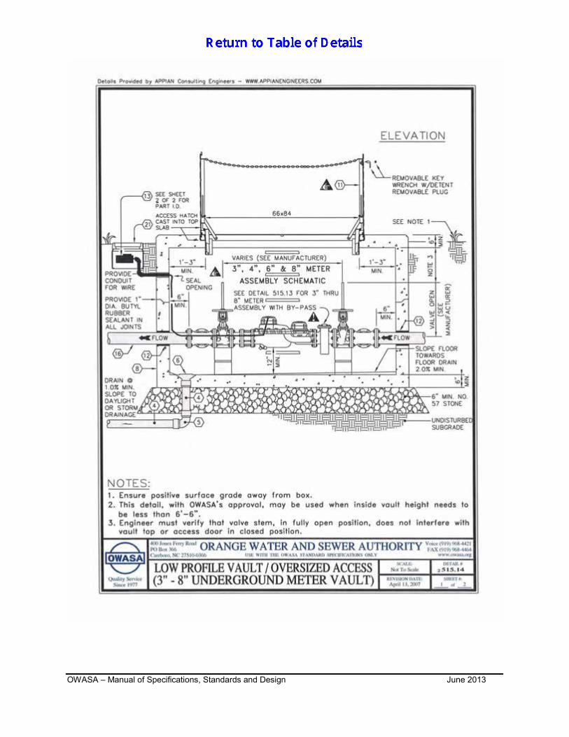
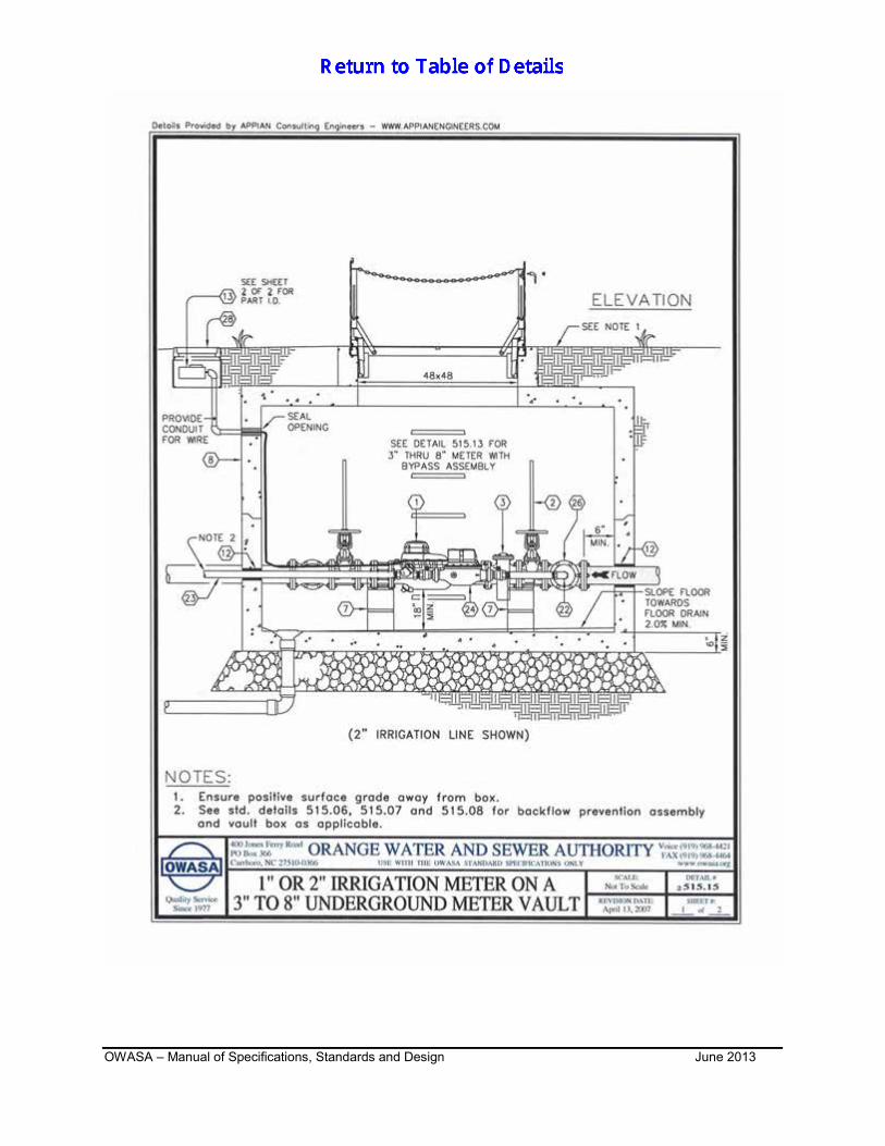
515.14 LOW PROFILE VAULT / OVERSIZED ACCESS (3” – 8” UNDERGROUND METER VAULT) 515.15 1” OR 2” IRRIGATION METER ON A 3” TO 8” UNDERGROUND METER VAULT 516.01 STANDARD WATER MANHOLE FRAME AND COVER
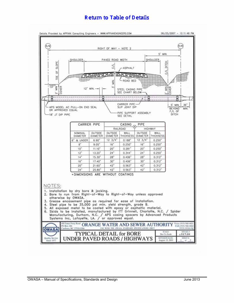
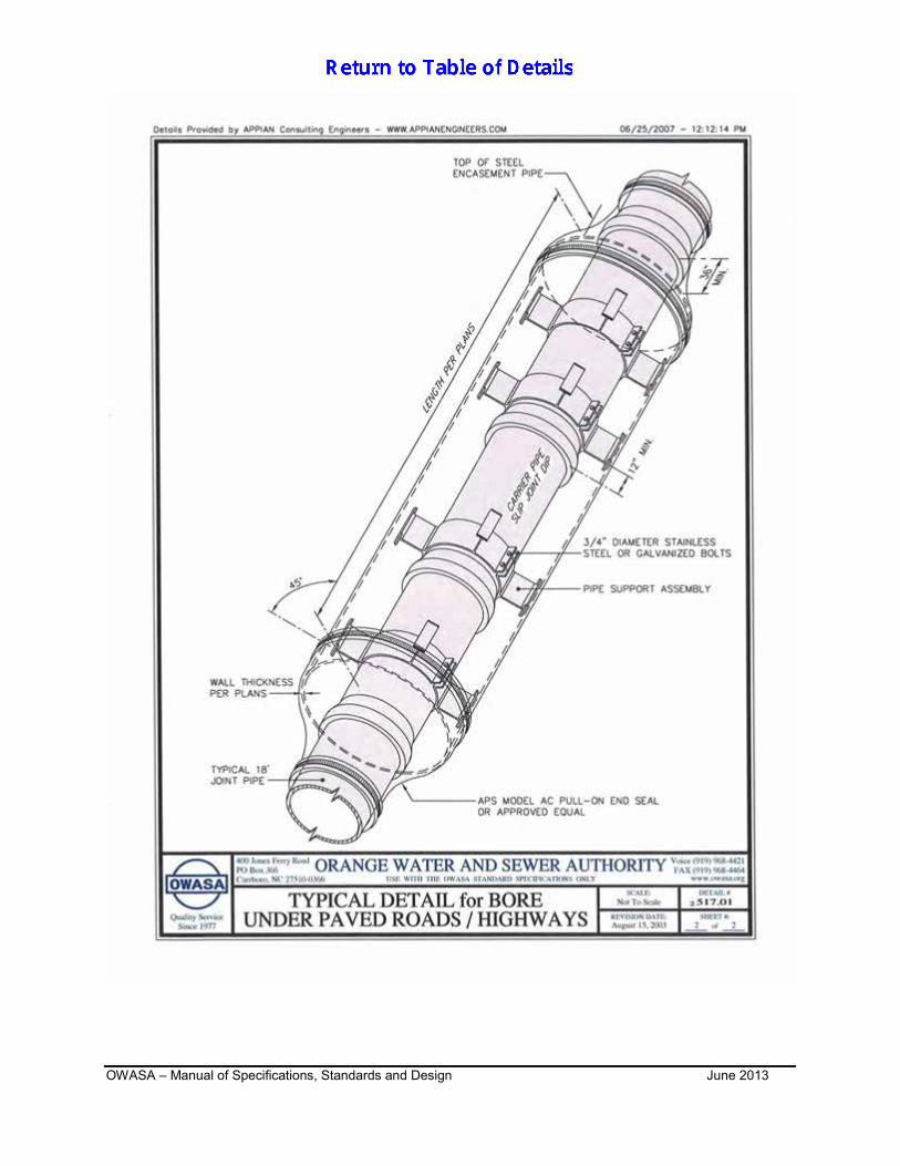
517.01 TYPICAL DETAIL FOR BORE UNDER PAVED ROADS/HIGHWAYS TABLE OF DETAILS Detail Number
SEWER DETAILS
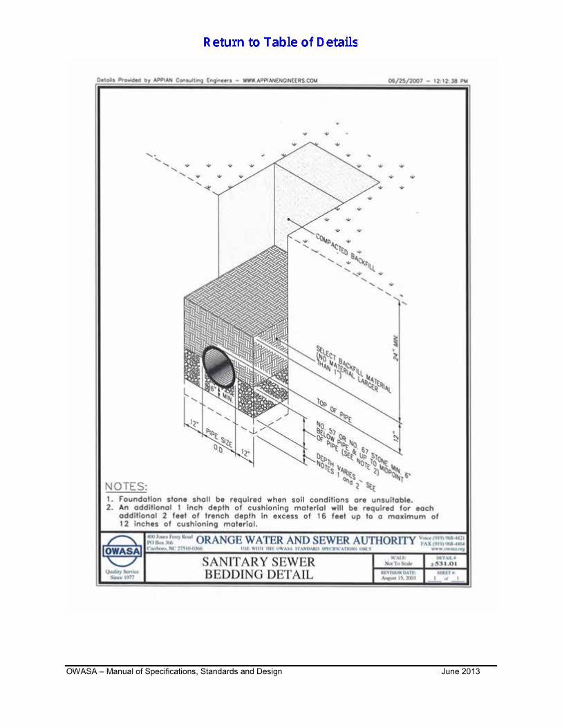
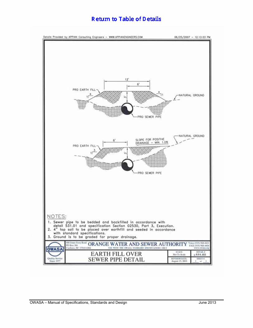
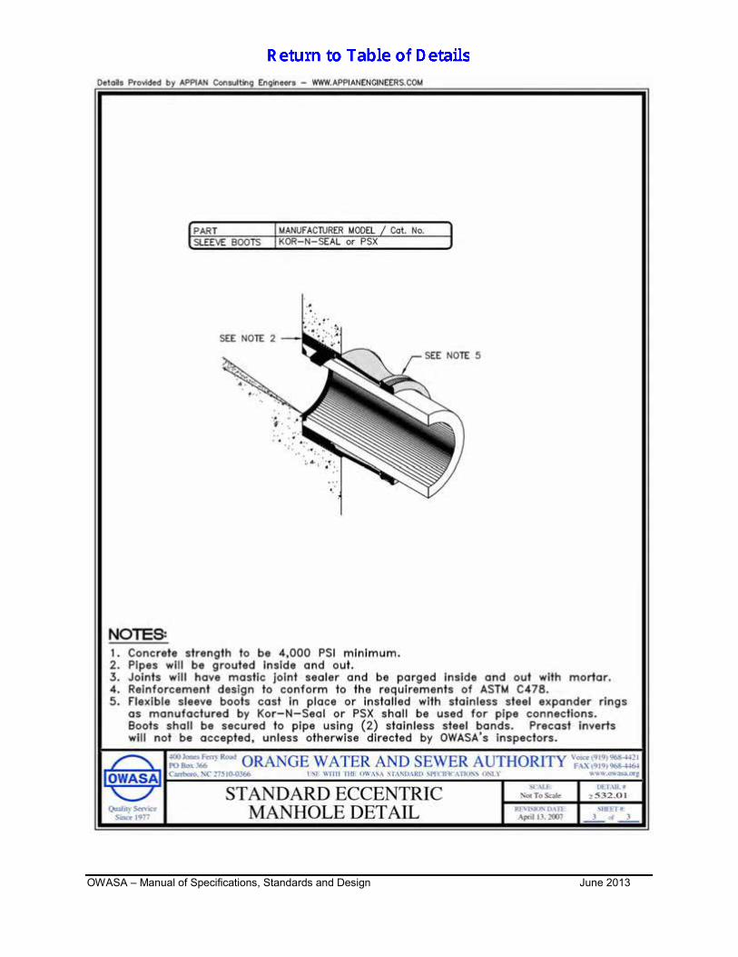
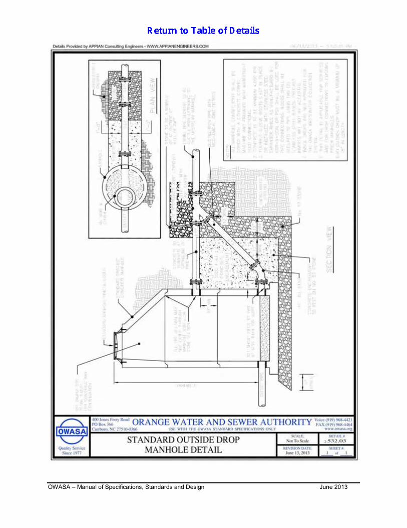
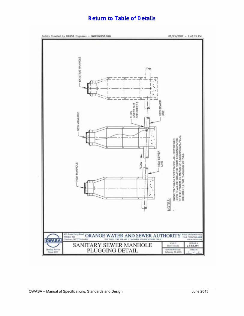
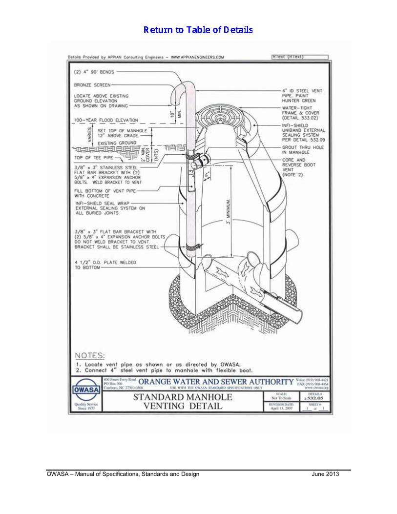
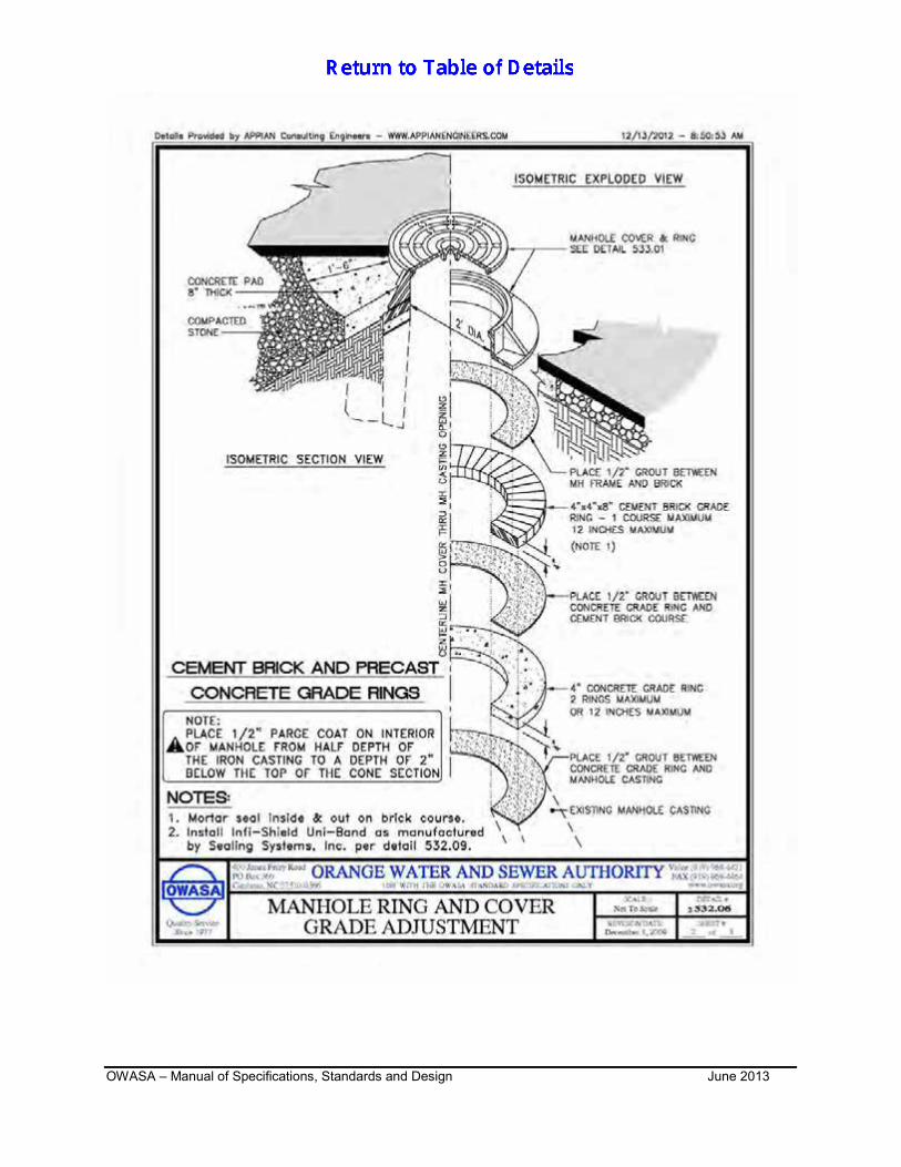
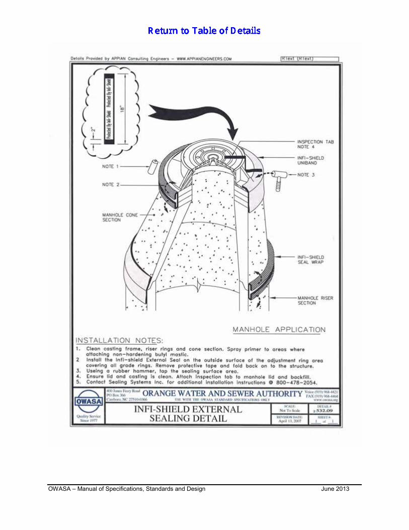
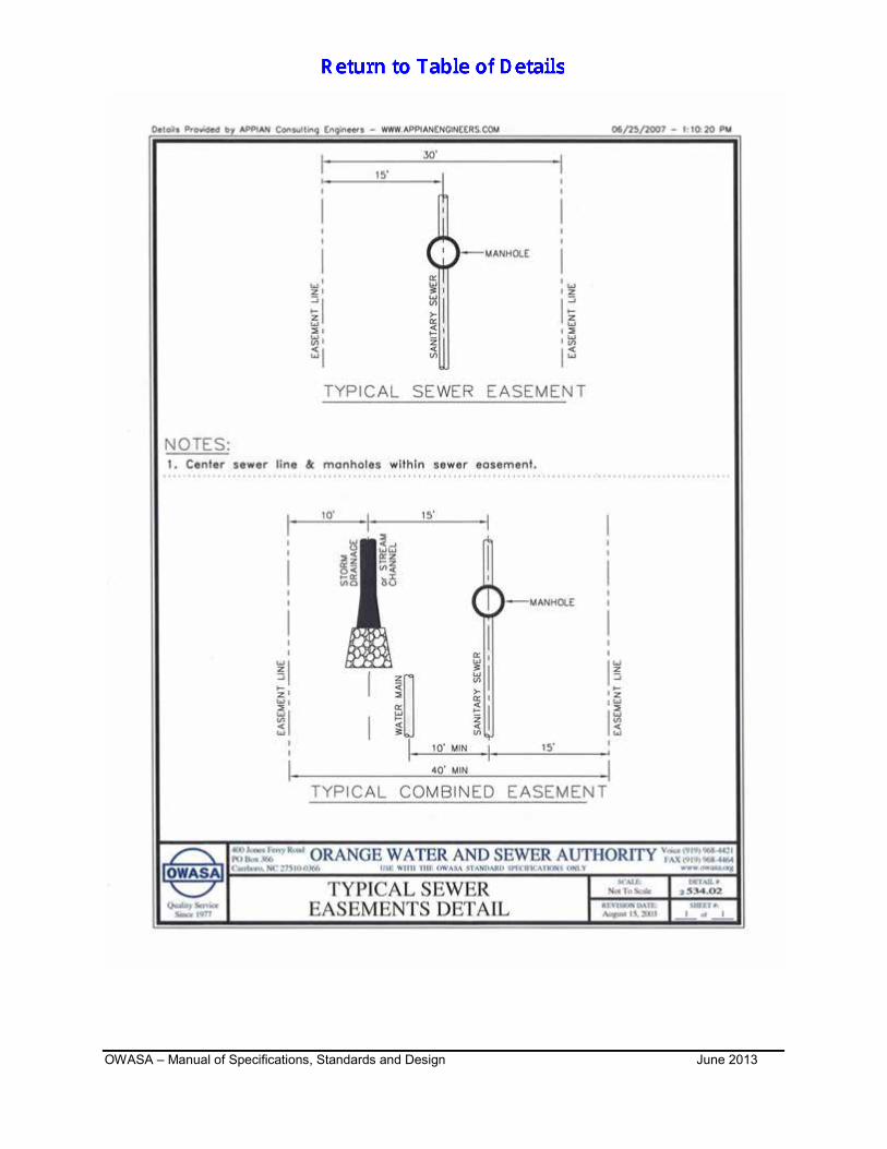
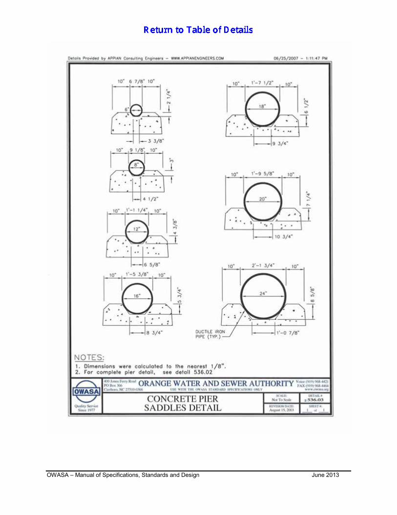
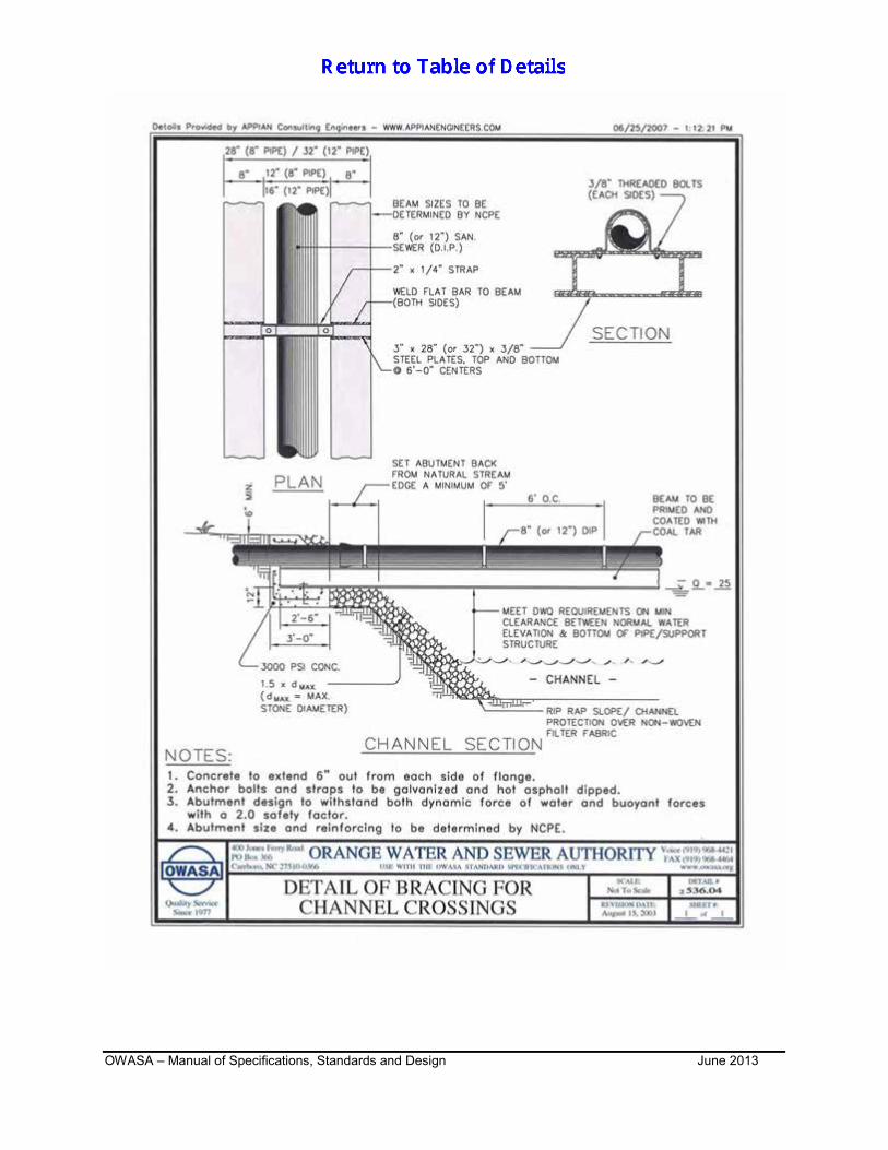
- SANITARY SEWER REVISION SUMMARY SHEET 531.01 SANITARY SEWER BEDDING DETAIL 531.02 EARTH FILL OVER SEWER PIPE DETAIL 532.01 STANDARD ECCENTRIC MANHOLE DETAIL 532.02 STANDARD SEWER INVERT PLANS FOR MANHOLE 532.03 STANDARD OUTSIDE DROP MANHOLE DETAIL 532.04 SANITARY SEWER MANHOLE PLUGGING DETAIL 532.05 STANDARD MANHOLE VENTING DETAIL 532.06 MANHOLE RING AND COVER GRADE ADJUSTMENT 532.07 STRUCTURE PROTECTION UNFINISHED ROAD GRADE 532.08 PRECAST CONCRETE DOGHOUSE MANHOLE 532.09 INFI-SHIELD EXTERNAL SEALING DETAIL 533.01 SANITARY SEWER MANHOLE FRAME AND COVER 533.02 SANITARY SEWER WATERTIGHT MANHOLE FRAME AND COVER 534.01 4” SEWER TAP AND STUB-OUT PAVED APPLICATION CLEAN OUT 534.02 TYPICAL SEWER EASEMENT DETAIL 535.01 CASING PIPE PEDESTRIAN BARRIER 536.01 CONCRETE COLLAR DETAIL 536.02 CONCRETE PIER DETAIL 536.03 CONCRETE PIER SADDLES DETAIL 536.04 DETAIL OF BRACING FOR CHANNEL CROSSINGS 536.05 SANITARY SEWER LINE AND MANHOLE ABANDONMENT DETAIL 536.06 536.07
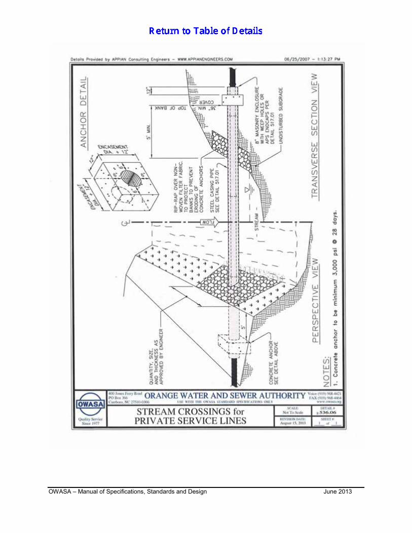
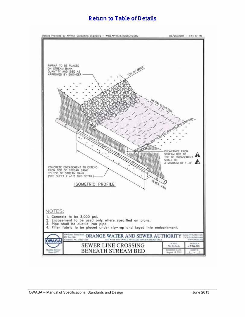
STREAM CROSSINGS FOR PRIVATE SERVICE LINES BLANK SHEET 536.08 SEWER LINE CROSSING BENEATH STREAM BED
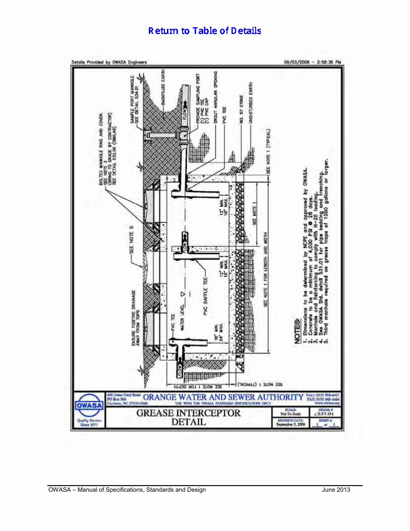
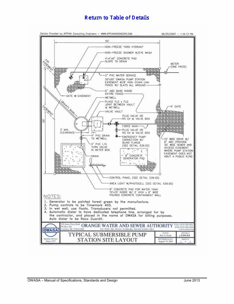
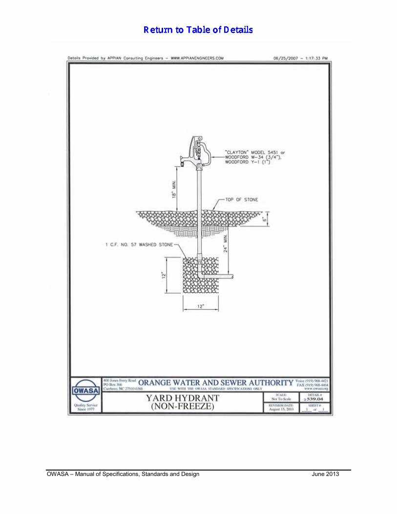
537.01 GREASE INTERCEPTOR DETAIL 538.01 COMBINATION AIR VALVE AIR RELEASE MANHOLE 539.01 TYPICAL SUBMERSIBLE PUMP STATION SITE LAYOUT 539.02 TYPICAL EMERGENCY PUMP CONNECTION 539.03 TYPICAL CHAIN-LINK FENCE DETAIL – 8 FT. HEIGHT 539.04 YARD HYDRANT (NON-FREEZE) 539.05 PUMP STATION SERVICE PANEL DETAIL
OWASA – Manual of Specifications, Standards and Design Foreword January 2013 Page i
FOREWORD About OWASA OWASA is the public, nonprofit water and sewer utility serving the Carrboro-Chapel Hill community. OWASA's 9-member Board of Directors is appointed by the Chapel Hill Town Council, the Carrboro Board of Aldermen and the Orange County Board of Commissioners. OWASA has served the community since February, 1977, when the University of North Carolina at Chapel Hill and the Towns of Carrboro and Chapel Hill transferred their water and wastewater facilities to OWASA. Our services are funded entirely from our rates and fees, which reflect legal requirements to use the "cost of service" approach in setting rates, fees, and charges. OWASA provides services within a basic framework of State and Federal law, our 1977 Agreements of Sale and Purchase with the University and the Towns, certain contractual obligations to holders of OWASA Revenue Bonds, and agreements with the Towns and County regarding the extension and provision of public water and sewer services. OWASA is an equal opportunity employer and a member of the American Water Works Association and the Water Environment Federation. Manual Introduction The latest approved version of OWASA‟s Standard Specifications was prepared in September 1990. OWASA‟s Standard Specifications explain the water and sewer extension and construction process and establish minimum acceptable guidelines or standards for the design and construction of water and sewer lines and appurtenances. Although the document still serves as a good reference manual and guide to contractors, there have been changes in materials, methods and procedures that need to be incorporated into a revised document. Since 1990, new and revised standard details had also been developed by OWASA staff, and need to be incorporated as revised Standard Specifications. This new Standard Specifications Manual was prepared by Appian Consulting Engineers, PA, Rocky Mount, NC for the Orange Water and Sewer Authority. The manual contains specific technical information related to the proposed construction of infrastructure improvements within the OWASA service area. The materials, improvement specifications, standard details, and design methodology contained herein are established as the minimum requirements for OWASA and have been determined to be reasonable as applicable to OWASA. This document has been compiled from current standards and practices used by OWASA, from improvement standards used in other areas of the State of North Carolina, and applicable enabling legislation of the State of North Carolina. Manual format This manual was prepared to facilitate ease of use by both the design engineers and the contractor. The various elements that comprise this book have been compiled from adopted policies and procedures, both current and new standard details, specifications, and practices. This manual contains the information needed by design engineers, developers, and contractors
OWASA – Manual of Specifications, Standards and Design Foreword January 2013 Page ii
to facilitate design, development, and construction within the OWASA service area. Additionally, the information contained herein is available on OWASA‟s website. Standard Specifications The standard specification section includes the following sections: Trenching, Backfilling and Compaction of Utilities, Water Distribution, and Sanitary Sewer.
Technical Specifications and details excluded from this manual: Erosion Control - permitting and plan review is administered by: NCDENR, Division of Land Quality, and Erosion and Sediment Control Planning and Design Manual, latest revision.
Street Repair and Paving – The Town of Chapel Hill, Town of Carrboro and/or the NCDOT will provide review and permitting of their facilities. The standard details provided herein are water and sewer construction details. All structures, as well as a few non-structure type standards, are high-quality drawings, when practical, in both isometric and exploded views. Standard Details Sections included in manual: Sewer Water
Design Section A design section has been provided which incorporates the following: regulatory requirements of the NCDENR, Division of Water Quality, NCAC Title 15A 2H .0200 Waste not Discharged to Surface Waters, NCDENR Division of Environmental Management, Public Water Supply Section, NCAC Title 15A Subchapter 18C, Rules for Governing Public Water Supply Systems, ASCE–Manuals of Reports on Engineering Practice-No. 60 “Gravity Sanitary Sewer
Design and Construction,” The “Recommended Standards for Sewage Works” by the Great Lakes-Upper
Mississippi River Board of State Sanitary Engineers, and The applicable requirements specific to OWASA.
To the best of their ability, the authors have insured that the information presented here is correct and that the procedures are reliable. The execution of an engineering design, however, involves the judgment of the design engineer, and only the engineer can ascertain whether a technique or item of information can be applied to a given situation.
OWASA – Manual of Specifications, Standards and Design Foreword January 2013 Page iii
Policy and Ordinance Rather than include the specific policies and ordinance in their entirety, a reference sheet has been provide listing key policies and ordinances. These policies and ordinances can be obtained directly from OWASA. Jurisdiction On or after August 15, 2003 this Manual of Specifications, Standards and Design shall be applicable to all new improvements and alterations in existing improvements lying within the regulatory jurisdiction of OWASA. Variance or Modification Any variances, alternate designs, construction methods and materials, not specifically prescribed herein, shall be subject to the approval of the Executive Director or his (her) designee. Copyright This is a copyrighted document. Reuse of the printed material or standard details contained in this manual, either in whole or in part, by private concerns or individuals for the purpose of monetary gain in the preparation of municipal public facilities manuals or similar documents, without the written permission of Appian Consulting Engineers, PA, is strictly prohibited.
OWASA – Manual of Specifications, Standards and Design Foreword January 2013 Page iv
Project Team: OWASA Michael Jakubiak, EI, Utilities Engineer and Project Team Leader (2003) Darren K. Berger, Engineering Associate and Project Team Leader (2007, 2011, 2012 Revision) Mason Crum, P.E., Director of Engineering and Planning (2007, 2012 Revision) Barbara Oslund, P.E., Engineering Manager, Capital Projects (2003) Bob Russell, Customer Relations Manager (2003) David Lewis, Jr., Purchasing Specialist (2003 and 2007 Revision) Donald Robinson, LSI, Engineering Technician (2003) Donnie Nolf, Construction Inspector (2003 and 2007 Revision) Elijah Williams, EI, Utilities Engineer (2003) John Greene, P.E., General Manager (2003 and 2007, 2012 Revision) M. Imtiaz Ahmad, P.E., Director of Engineering and Planning (2003) Mary Darr, P.E., Operations Engineer (2003 and 2007 Revision) Patrick Davis, Utilities Engineer (2003) Randy Horton, Assistant Distribution & Collection System Manager (2003 and 2007 Revision) Sandy Beckham, Engineering Technician (2003 and 2007 Revision) Ted Blake, Engineering Associate (2003 and 2007 Revision) Thurman Green, Distribution & Collection System Manager (2003 and 2007 Revision) Todd Spencer, P.E., Engineering Manager, System Development (2003 and 2007, 2011, 2012 Revision) F. Stuart Carson, P.E., Engineering Manager, Capital Improvements Program (2007, 2012 Revision) Joe Leo, Engineering Technician (2007, 2011, 2012 Revision) Nick Parker, Engineering Associate (2007, 2012 Revision) Adam Haggerty, Engineering Technician (2012 Revision) Mike Smith, Purchasing Specialist (2012) Appian Consulting Engineers, PA Bobby L. Joyner, P.E., Project/Team Leader and Author Pete Sokalski, EI, Assistant Project Manager Mike Gallina, CAD Supervisor Kevin Harrell, CAD Technician
OWASA – Manual of Specifications, Standards and Design Introduction January 2013 Page I-1
(Last revised 6/1/13) INTRODUCTION
1.1 PURPOSE This manual was created to explain the water and sewer extension process and to
establish standards for design and construction of water and sewer lines and appurtenances.
1.2 OWASA The Orange Water and Sewer Authority is a regional public water and sewer utility
established in 1977 to serve the Chapel Hill-Carrboro community and nearby areas. 1.3 DEFINITIONS
Adjacent and Abutting This policy for water and sewer projects ensures the orderly development of the system by requiring that each property benefiting from the water or sewer lines must have at least a part of that line abutting or adjacent to the property. This policy prevents properties from simply installing long laterals across neighboring properties or connecting to neighboring property‟s laterals to reach public sewer or water lines. Applicant The person or company which is proposing new connections to or extension of the water distribution and wastewater collection systems, also known as the developer. Approved Equal Approved equal is the annotation given to a product or material that has been approved by OWASA as a substitute for the product or material specified in the specifications or standard details. “Approved Equal” products and materials must be approved by the OWASA Product and Design Review Committee. Availability Fees These are fees collected for each new connection to the water and sewer systems. The availability charge is a charge to collect for the demand on the infrastructure of the system as represented by meter size and use. Collector A collector is a sewer pipe typically 8 inches in diameter into which the wastewater from two or more laterals (individual homeowner's pipe) is discharged and which subsequently discharges into a main, interceptor, or other collector. Conditional Use Permit This is a permit from a zoning authority (e.g. the Towns of Chapel Hill and Carrboro) which allows a plot of land to be used for a project provided specific conditions are met. Contractor The contractor is hired by the owner/developer to install the water and/or sewer lines in accordance with approved plans.
OWASA – Manual of Specifications, Standards and Design Introduction January 2013 Page I-2
Cross Connection Any physical connection between a potable water supply system and any other piping system, sewer fixture, container, or device, whereby water or other liquids, mixtures, or substances may flow into or enter the potable water supply system; Any potable water supply outlet which is submerged or is designed or intended to be submerged in non-potable water or in any source of contamination or; An air gap, providing a space between the potable water pipe outlet and the flood level rim of a receiving vessel of less than twice the diameter of the potable water pipe. Developer The person or company responsible for the design and construction of water and sewer lines to serve their property. Director of Engineering and Planning The Director of Engineering and Planning for OWASA or his/her designee. Division of Environmental Health (DEH) Division of Environmental Health is one department of the North Carolina Division of Environmental Health and Natural Resources. It is responsible for oversight of water plant operations, water distribution, water supplies, water quality, and facility permitting for compliance with state and federal regulations. Division of Water Quality (DWQ) Division of Water Quality is one department of the North Carolina Division of Environmental Health and Natural Resources. It is responsible for oversight of wastewater plant operations, collection systems, treatment plant effluent discharge, and sludge disposal including permitting for compliance with state and federal regulations. Easement A piece of private property which the owner grants to a public utility or government to use, maintain, access, and clear. The owner forfeits certain uses of the property. Easements are acquired through the owner's signing of an easement agreement, negotiation and monetary settlement or, if negotiations fail, condemnation under eminent domain statutes. Elastomers (Gaskets, o-rings, etc) Approved elastomeric materials are: EPDM, fluorocarbon, silicone, or isobutylene-isoprene. Executive Director The Executive Director of OWASA. Force Main A force main is a pressure pipe joining the pump discharge at a wastewater pumping station with a point of gravity flow. Gravity Flow System This is a system of conduits in which no wastewater pumping is required. Sewage flows by gravity from service points to public sewer lines.
OWASA – Manual of Specifications, Standards and Design Introduction January 2013 Page I-3
Grinder Pump A grinder pump is a mechanical device that shreds solids and raises the fluid to a higher elevation through pressure sewers. Interceptor An interceptor is a sewer pipe which transports wastewater from collection sewers to a treatment facility. Lateral A water lateral is the pipe which connects a building to the water meter located on the customer's property. A sewer lateral is the pipe which connects a building to the collector sewer located in the street. In the OWASA system, both the water and sewer laterals are owned and maintained by the property owner. Local Planning Unit The local planning unit is the Planning Department and/or Planning Board of the Town of Chapel Hill, Town of Carrboro, Orange County, Durham County; or the appropriate planning office at the University of North Carolina at Chapel Hill or UNC Hospitals. National Pollutant Discharge Elimination System (NPDES) The federal government's system of controlling all discharge of pollutants from point sources into U.S. waterways. NPDES permits discharges into navigable waters from all point sources of pollution, including industries, municipal treatment plants, large agricultural feed lots, and return irrigation flows. Lift Station A lift station is a specific kind of pump station. It is a small sewer pump used when gravity can no longer carry wastewater through sewer. The lift station pumps wastewater from a lower elevation to a higher elevation so that gravity can again be used to carry the wastewater. OWASA‟s Engineer The Project Engineer or his or her authorized representative. Plat A plat is a map or chart of a subdivision or piece of land that provides survey information on lot size and location and often includes the tax identification code. Professional Engineer An engineer certified and licensed by the North Carolina Board of Examiners for Engineers and Surveyors. Project Engineer The Project Engineer is the engineer hired by the owner/developer to prepare a set of plans and specifications for the water and sewer utilities that serve the project. The Project Engineer is also responsible for construction administration of the project. The Project Engineer will prepare plans in accordance with OWASA Standard Specifications, North Carolina Division of Environmental Health and Natural Resources, and all other federal, state, and local regulations pertaining to the project.
OWASA – Manual of Specifications, Standards and Design Introduction January 2013 Page I-4
The Project Engineer will submit plans for review to OWASA, make revisions as necessary to comply with OWASA guidelines, observe construction to ensure utilities are constructed in accordance with OWASA standards, and provide certification to OWASA and NCDENR that utilities were installed in accordance with approved plans. Public Sewer System Sewer lines, manholes, pump stations, force mains owned and maintained by OWASA. Public Water System Water mains and appurtenances owned and maintained by OWASA. Pump Station A pump station is a structure containing pumps, piping, valves, and other mechanical and electrical equipment for pumping water, wastewater, or other liquids. A pump station is used to pump wastewater from a sewer main of lower elevation to a sewer main of higher elevation. A lift station; often used synonymously with the term pump station, provides a vertical lift to sewage in order for it, in many instances, to again flow by gravity. Punch List The punch list identifies deficiencies of the water and sewer construction found during the pre-final inspection. A punch list is generated by the OWASA Inspector after a pre-final Inspection. Right-of-Way Right-of-way is land or property that has been dedicated to a public entity for use by the public, the entity itself, or both and is maintained by that entity. Sanitary Sewer A sewer that carries liquid and waterborne wastes from residences, commercial buildings, industrial plants, and institutions, together with minor quantities of ground, storm, and surface waters that are not admitted intentionally. The spent or used water of a community or industry which contains dissolved and suspended matter. Service Area This is an area that a utility serves or is authorized to serve. Special Use Permit This is a permit from a zoning authority (e.g. the Towns of Chapel Hill and Carrboro) which allows a plot of land to be used for a purpose other than its normally permitted use. Supplemental Fire Protection Fire protection services include fire lines that feed sprinkler systems and fire hydrants that are not a part of the general hydrant service supplied by OWASA to the public but at no charge. Taps The connection of a new main for extension or service line to public water or sewer lines
OWASA – Manual of Specifications, Standards and Design Introduction January 2013 Page I-5
that are in-service. OWASA must make all taps to in-service mains. A fee is charged to cover the expense of time and equipment. Third Party Project This is a water or sewer project that is being constructed by a developer or party other than OWASA. Third party projects are dedicated to OWASA upon completion and become part of the public water and/or sewer system.
1.4 ABBREVIATIONS AASHTO American Association of State Highway Transportation Officials ANSI American National Standards Institute ASTM American Society for Testing Materials AWWA American Water Works Association DEH North Carolina Division of Environmental Health DENR Department of Environment, Health, and Natural Resources DWQ North Carolina Division of Water Quality NCDOT North Carolina Department of Transportation NPDES National Pollutant Discharge Elimination System NSF National Sanitation Foundation OWASA Orange Water and Sewer Authority UNC University of North Carolina USGS United States Geological Survey
OWASA – Manual of Specifications, Standards and Design June 2013 Page 00950-1
00950 – MEASUREMENT & PAYMENT (Last revised 6-1-13) SUGESTED SEARCH WORDS FOR THIS SECTION THIS SECTION APPLIES ONLY TO OWASA CAPITAL IMPROVEMENT PROJECTS Measurement & Payment - Trenching, Backfilling & Compaction of Utilities Measurement & Payment - Sewer Measurement & Payment - Water
1.1 TRENCHING, BACKFILLING AND COMPACTION OF UTILITIES
Measurements for purpose of payment shall be in accordance with the unit quantities stated in the proposal as defined below. Whenever units of measure (i.e. linear feet, each, and similar units of measurement) are mentioned in a proposal, it shall be interpreted to mean the unit installed in accordance with the plans and specifications, and ready for use. Prices for the following bid items shall include all labor, materials, tools, equipment, and other incidentals necessary to complete the work as shown on the plans and in accordance with these specifications. A. Access or Haul Roads: Measurement: Any grading or excavation required for equipment travel during the
course of construction as well as erosion control, removal, restoration, and seeding and ground cover shall be included in other items bid.
Payment: Included in other items bid. Not a pay item. B. Aggregate Backfill: Measurement: Coarse granular fill will be measured by the ton in place in the
trench. Payment: Price per ton for coarse granular fill shall include all materials, equipment,
and labor required to furnish and install clean coarse granular stone in the locations designated by OWASA‟s Engineer. For purposes of measurement, 1 cubic yard of #57 stone = 1.5 tons.
C. Bedding, Crushed Stone for: Measurement: Bedding stone is considered to be incidental to the cost of the pipe. Payment: Not a pay item. D. Clearing and Grubbing, Lightly Wooded Areas: Measurement: Measurement for clearing and grubbing will be by the acre. Width
shall not exceed width as defined in the disturbing and construction limits criteria of water and/or sewer construction.
00950 – MEASUREMENT AND PAYMENT
OWASA – Manual of Specifications, Standards and Design June 2013 Page 00950-2
Payment: Price per acre for clearing and grubbing in lightly wooded areas shall include all material, equipment, and labor required to clear and grub lightly wooded areas in accordance with these specifications. Lightly wooded areas shall be defined as areas where the prevalent vegetation consists of trees less than 12 inches in diameter. The price shall also include the removal and disposal of items that cannot be mulched or built into brush piles.
E. Clearing and Grubbing, Heavily Wooded Areas: Measurement: Measurement for clearing and grubbing will be by the acre. Width
shall not exceed width as defined in the disturbing and construction limits criteria of water and/or sewer construction.
Payment: Price per acre for clearing and grubbing in heavily wooded areas shall
include all material, equipment, and labor required to clear and grub heavily wooded areas in accordance with these specifications. Heavily wooded areas shall be defined as areas where the prevalent vegetation consists of trees 12 inches or greater in diameter. The price shall also include the removal and disposal of items that cannot be mulched or built into brush piles.
F. Concrete Encasement: Measurement: Payment for furnishing concrete encasement will be at the unit price
bid per cubic yard for the class of concrete stated in the proposal, such price to be paid in addition to that paid per foot of water or sewer main.
Payment: The unit priced stated in the proposal shall include the cost of additional
depth of excavation, forming, the furnishing and placing of concrete, cofferdams if applicable, laying of pipe line to grade but excluding the cost of the pipe itself, complete in place, including all labor, equipment and material necessary, and all other work incidental to the complete installation of the concrete encasement in accordance with the specification and details shown on the plans. Payment will be made to neat lines of construction shown on the plans with no allowance being made for extra ditch width.
G. Concrete Anchors and Piers: Measurement: This item will be measured on and each basis for Concrete Anchors
and Piers. Concrete thrust blocking is considered incidental to the cost of water lines and is not a pay item.
Payment: This item will be paid for at the contact unit price bid for Concrete Anchors
and Piers, complete in place, including all labor, equipment, and material necessary for furnishing, excavating, forming, installing, backfilling, and all other work incidental to the complete installation of the concrete anchors and piers in accordance with the specification and details shown on the plans. Payment will be made to neat lines of construction shown on the plans with no allowance being made for extra ditch width.
H. Concrete – Miscellaneous Unformed: Measurement: Concrete, except that used in manholes, will be measured in cubic
yards of unformed concrete actually placed. Typical uses include concrete collars (slope anchors), cradles, and all other miscellaneous concrete related to water or sewer line installation.
00950 – MEASUREMENT AND PAYMENT
OWASA – Manual of Specifications, Standards and Design June 2013 Page 00950-3
Payment: This item will be paid for at the contract unit price per cubic yard for un-formed concrete for collars, cradles, and all other miscellaneous concrete related to water and sewer line construction, in place, including all material, equipment, and labor to place the concrete in the locations shown on the construction drawings and/or as directed by OWASA‟s Engineer including the cost of removing and disposing of the material replaced by the concrete. Payment will be made only for the quantities and dimensions as shown on drawings or applicable details. Price does not include pipe.
I. Excavation and Backfill: Measurement and Payment: All excavation and backfill shall be included in the cost
of the other items bid – not a pay item. When the removal of existing structures or materials is classified separately as a
contract pay item, payment will be made in accordance with the contract price; otherwise, such work will be considered as incidental work and will not be paid for directly, but the cost shall be included in the unit price for other items of work. In either case, such price or prices shall be full compensation for all labor, materials, tools, equipment, and incidentals necessary to complete the work.
J. Exploratory Excavation: Measurement: Such excavation, where ordered by OWASA, will be measured by
the cubic yard. Payment: The cost of such excavation, where ordered by OWASA, will be paid at
the contract unit price bid, per cubic yard. K. Flowable Fill Concrete: Measurement: Measurement shall be by the cubic yard of concrete placed,
regardless of the specified strength. Payment: Paid for in place by the cubic yard. L. Foundation Stone: Measurement: Foundation stone used in stabilizing the bottom of trenches will be
field measured in the trench and converted to tons, complete in place. For purposes of measurement, 1 cubic yard of #57 stone = 1.5 tons.
Payment: When the use of foundation stone is directed by OWASA‟s Engineer,
foundation stone shall be paid for at the contract unit price for foundation stone by the ton. Payment shall include all materials and labor incidental to the placing of the stone and any additional extra depth of trench or excavation necessary to accommodate the stone including disposal of unusable material necessary to allow for placement of the foundation stone.
M. Pavement Removal and Replacement: Measurement: Where pavement is encountered, as shown on the plans, pavement
removal and replacement will be measured by the linear foot along the centerline of construction regardless of the existing pavement material or depth. See
00950 – MEASUREMENT AND PAYMENT
OWASA – Manual of Specifications, Standards and Design June 2013 Page 00950-4
Specifications Section 02275– Trenching, Backfilling, and Compaction of Utilities, paragraph 3.7, Pavement Repair and Replacement.
Payment: This item will be paid for at the contract unit price per linear foot for
pavement removal and replacement. The unit price bid shall include all labor, tools, equipment, and material necessary to complete the work and shall include, but is not necessarily limited to, saw cutting the pavement, removal of existing pavement materials which are not suitable for backfilling the trench from the job, placement of suitable backfill material, and the cost for compaction and compaction testing by a certified and approved laboratory. In the case of pavement cut and removal, such price or prices shall include the cost of the required permit for cutting pavement, unless permit fees are included as a bid item in the Contract Documents. Extra width will not be measured for payment and there will be no extra payment for any of the above work, the cost of which shall be included in the unit price bid, for pavement removal and replacement.
N. Portland Cement Concrete Sidewalk: Measurement: Where existing concrete sidewalk is encountered, as shown on the
plans, removal and replacement will be measured by the square foot of sidewalk ordered removed and replaced by OWASA, regardless of the depth of the existing sidewalk.
Payment: This item will be paid for at the contract unit price per square foot for
removal and replacement of concrete sidewalk, depth to match the depth removed with no extra compensation for depth. The unit price bid shall include all labor, tools, equipment, and material necessary to complete the work and shall include, but is not necessarily limited to, saw cutting the sidewalk, removal of all existing materials, which are not suitable for backfill in the trench from the job, compaction of the trench, and replacement of the sidewalk.
O. Remove and Replace Asphalt Drive and Remove and Replace Concrete Drive: Measurement: Where either an existing asphalt or concrete drive is encountered,
as shown on the plans, pavement removal and replacement will be measured by the linear foot along the centerline of construction regardless of the existing pavement material or depth.
Payment: This item will be paid for at the contract unit price per linear foot for
removal and replacement of either asphalt or concrete drives. The unit price bid shall include all labor, tools, equipment, and material necessary to complete the work and shall include, but is not necessarily limited to, saw cutting the pavement, removal of all paving materials which are not suitable for backfill in the trench from the job, and compaction of the trench. Extra width will not be measured for payment and there will be no extra payment for any of the above work, the cost of which shall be included in the unit price bid, for removal and replacement of asphalt or concrete drives.
P. Resurfacing Existing Pavement: Measurement: Payment for resurfacing existing pavement will be made at the unit
price bid per square yard in accordance with field measurements made by OWASA.
00950 – MEASUREMENT AND PAYMENT
OWASA – Manual of Specifications, Standards and Design June 2013 Page 00950-5
Payment: The unit price bid shall include all labor, tools, equipment, and material necessary to complete the work and shall include, but is not necessarily limited to, saw cutting the pavement if necessary, adjusting valves and manholes, and meeting density requirements. The Contractor shall furnish OWASA with all asphalt weight tickets at the time the work is accomplished. The computed yield, arrived at by dividing the weight used by the measured area, shall be a minimum of 200 pounds per square yard. In those areas where the work is acceptable to the NCDOT and OWASA, yet the computed yield is less than 200 pounds per square yard, payment will be made in direct ratio to the square of the actual yield to the square of 200 pounds per square yard.
Q. Rock Excavation: Measurement: Where rock excavation is to be measured for payment, quantities will
be as determined by OWASA. Rock excavation will be measured by the cubic yard. For pay purposes, dimensions shall be computed as the difference in elevation between the top and bottom of the rock (as determined by OWASA) multiplied by the specified trench ditch width for the pipe size being laid. Where rock is encountered in the bottom of the trench, the maximum depth for payment purposes shall be 6 inches below the bottom of the pipe. Rock excavation shall consist of the removal and satisfactory disposal of all materials, which in the opinion of OWASA‟s Engineer, cannot be excavated except by drilling, blasting, “jack hammering or hoe ramming.” All boulders containing a volume of more than one-half cubic yard will be classified as rock.
Payment: Rock excavation will be paid for at the contract unit price per cubic yard
for rock excavation and shall include all labor, materials, tools, equipment, and incidentals necessary to excavate and dispose of rock off site, backfilling the excavated trench to the bottom of the pipe with select backfill material, and shall include the cost of removing all excavated materials which are not suitable for backfill. No payment will be made for rock which has been excavated subsequent to ripping operation.
R. Sheeting and Bracing (Piling): Measurement and Payment: Payment for sheeting and bracing, except when
ordered to be left in place, and all other work incidental to sheeting and bracing, shall not be made separately unless specified or as shown on the plans or as directed by OWASA, but shall be included in the bid price for other items.
When specified, payment for “Timber Sheeting Left in Place” shall be made at the
contract unit price bid per 1000 board feet. When specified, payment for “Steel Sheet Piling” shall be made at the contract unit
price bid per square foot. When specified, payment for “Steel Sheet Piling Left in Place” shall be made at the
contract unit price bid per square foot. S. Sodding, Fertilizing, Seeding, and Fine Grading: Measurement: Measurement of surfaces to be sodded or seeded shall be measured
to the nearest 1/10 acre for the class specified. Sodding, fertilizing, seeding, and fine grading shall be provided as described in Section 02275, Trenching, Backfilling,
00950 – MEASUREMENT AND PAYMENT
OWASA – Manual of Specifications, Standards and Design June 2013 Page 00950-6
and Compaction of Utilities. Extra compensation will not be made for additional seeding beyond all limits of construction as defined in applicable section.
Payment: Payment for sodding, fertilizing, seeding, and fine grading will be at the
contract unit price per acre for sodding, fertilizing, seeding, and fine grading as described in Section 02275, Trenching, Backfilling, and Compaction of Utilities. No compensation will be made for reseeding, if required. The cost of restoring areas located beyond the designated area(s) shall be borne by the Contractor.
T. Trench Borrow - Select: Measurement: Trench excavation determined to be unusable by OWASA‟s
Engineer, or his representative, resulting from material which may be non-compactable, naturally wet (when removed from trench), and otherwise unusable due to too high a moisture content for compaction (as opposed to unprotected soil exposed carelessly to rain which becomes unusable in which case there is no claim for payment for Trench borrow). Trench borrow shall be measured by the cubic yard of material removed from the trench, limiting the trench width to a maximum of 2 feet plus the pipe OD.
Payment: Trench borrow shall be paid by the cubic yard for material placed in the
trenches, compacted and in place. Trench borrow for water lines shall be included in the contract unit price per linear foot bid for water line (see paragraph 1.2 EE of this specification).
U. Other: Other items shall be paid for as stated in the Proposal.
1.2 WATER
Measurements for purpose of payment shall be in accordance with the unit quantities stated in the proposal as defined below. Whenever units of measure (i.e. linear feet, each, and similar units of measurement) are mentioned in a proposal, it shall be interpreted to mean the unit installed in accordance with the plans and specifications, and ready for use. Prices for the following bid items shall include all labor, materials, tools, equipment, and other incidentals necessary to complete the work as shown on the plans and in accordance with these specifications.
A. Aggregate Backfill: Measurement: Coarse granular fill will be measured by the ton in place in the
trench. Payment: Price per ton for coarse granular fill shall include all materials,
equipment, and labor required to furnish and install No. 57 stone in the locations designated by OWASA‟s Engineer. For purposes of measurement, 1 cubic yard of #57 stone = 1.5 tons.
B. Bedding Stone for Pipe: Measurement: When called for in the proposal or on the plans, aggregate material
used for bedding water lines will be measured by the ton of pipe bedding material placed.
00950 – MEASUREMENT AND PAYMENT
OWASA – Manual of Specifications, Standards and Design June 2013 Page 00950-7
Payment: Pipe bedding stone will be paid for at the contract unit price per ton for pipe bedding material, complete and in place.
C. Concrete Encasement: Measurement: Payment for furnishing concrete encasement will be at the unit price
bid per cubic yard for the class of concrete stated in the proposal, such price to be paid in addition to that paid per foot of water main.
Payment: The unit priced stated in the proposal shall include the cost of additional
depth of excavation, forming, the furnishing and placing of concrete, cofferdams, laying of pipe line to grade but excluding the cost of the pipe itself, complete in place, including all labor, equipment and material necessary, and all other work incidental to the complete installation of the concrete encasement in accordance with the specification and details shown on the plans. Payment will be made to neat lines of construction shown on the plans with no allowance being made for extra ditch width.
D. Concrete Piers: Measurement: This item will be measured on and each basis for concrete piers. Payment: This item will be paid for at the contract unit price bid for concrete piers
complete in place, including all labor, equipment and material necessary, for furnishing, excavating, forming, installing, backfilling, and all other work incidental to the complete installation of the concrete piers in accordance with the specification and details shown on the plans. Payment will be made to neat lines of construction shown on the plans with no allowance being made for extra ditch width.
E. Connecting to Existing Mains: Not a pay item. Fittings and specialty items used in making the connections will be
measured and paid for at the unit price bid by the Contractor for “Fittings” and at the unit price bid for “Tapping Tees and Valve.”
F. Copper Tubing (Pipe) for Water services (open cut): Measurement: Measurement of copper pipe for water services shall be made by
the linear foot of pipe through all fittings from the center of the water main to the center of the water meter box.
Payment: The accepted quantity of water service pipe shall be paid for at the
contract unit bid price per linear foot of the size indicated on the drawings, complete and in place, at a minimum depth of 24 inches. The price shall include all equipment, labor, and materials for installation, complete in place, to include testing and disinfection.
G. Copper Tubing (Pipe) for Water services (by Jacking or Boring): Measurement: Jacking water services will be measured by the linear foot of pipe
through all fittings from the center of the water main to the center of the water meter box.
00950 – MEASUREMENT AND PAYMENT
OWASA – Manual of Specifications, Standards and Design June 2013 Page 00950-8
Payment: The accepted quantity of jacked service pipe shall be paid for at the contract unit bid price per linear foot of the size indicated on the drawings, complete and in place. This price shall include all equipment, labor, and materials for installation, complete in place, including testing and disinfection.
H. Ductile Iron Pipe: Measurement: By the linear foot. All pipes shall be measured from the exact
beginning of the pipe to the end of the line without deduction for fittings (i.e. fittings and valves) and shall be made through casings. Hydrants leads will be measured as line.
Payment: The accepted quantities of water line pipe will be paid for at the contract
unit price per linear foot of the type and size pipe specified (fittings, valves, and specialty items are paid separately), complete in place. This price shall include labor, equipment, materials, trench excavation (excluding rock), shoring, or use of trench box, installation, concrete thrust blocking, making connections to existing mains, installing in existing casing, pumping, backfilling, compaction, testing of failed trenches, disposal of excess material, pressure testing, chlorinating and bacteriological testing, and all other work incidental to the complete installation of the mains in accordance with these specifications. Fittings, valves, and specialty items are paid separately.
I. Ductile Iron Pipe, Bored and Jacked: Measurement: Measurement of Ductile Iron Pipe, bored and jacked, shall be
measured by the linear feet of pipe installed. Bored and jacked Ductile Iron Pipe shall include any excavation, any backfill, bore, jacking, the pipe, dewatering, clean up, restoration, and any other work required for a complete in place installation.
Payment: Ductile Iron Pipe, bored and jacked will be paid for at the contract unit
price per linear foot for pipe bored, complete and in place. The price shall be full compensation for pipe, labor, equipment, and all other work incidental to the complete installation of the mains in accordance with these specifications. Fittings, valves, and specialty items are paid separately.
J. Encasement Pipe (bored): Measurement: Steel casing pipe of the wall thickness and diameter specified will
be measured by the linear feet of steel casing pipe installed. Encasement of water lines by the dry bore and jacking method shall include any
excavation, any backfill, the encasement pipe, bore, jacking, spiders, drain pipe, french drain, the end seals, dewatering, clean up, restoration, and any other work required for a complete in place installation.
Payment: Steel casing pipe will be paid for at the contract unit price per linear foot
per diameter per thickness for steel casing pipe bored, complete and in place. However, the bore shall be paid one time on a linear foot basis and no extra compensation will be paid for failures and the subsequent withdrawal and re-jacking attempts. Lines off either on grade or alignment shall be rejected or corrected in a manner approved by OWASA‟s Engineer. The cost of the carrier pipe is not to be included (see paragraph 1.3 F of this Section).
00950 – MEASUREMENT AND PAYMENT
OWASA – Manual of Specifications, Standards and Design June 2013 Page 00950-9
K. Encasement Pipe (open cut): Measurement: Steel casing pipe of the wall thickness and diameter specified will
be measured by the linear feet of steel casing pipe installed. Encasement of water lines by the open cut method shall include any excavation,
any backfill, the encasement pipe, spiders, drain pipe, french drain, the ends seals, dewatering, clean up, restoration, and any other work required for a complete in place installation.
Payment: Steel casing pipe will be paid for at the contract unit price per linear foot
per diameter per thickness for steel casing pipe installed by the pipe open cut, complete and in place. Lines off either on grade or alignment shall be rejected or corrected in a manner approved by OWASA‟s Engineer. The cost of the carrier pipe is not to be included (see paragraph 1.3 F of this Section).
L. Excavation and Backfill: Measurement and payment: In accordance with Section 02275, Trenching,
Backfilling, and Compaction of Utilities, all excavation and backfill shall be included in the cost of the other items bid – not a pay item.
M. Fittings and Accessories: Measurement: Fittings and specialty items used in conjunction with ductile iron
pipe will be measured per each. Payment: Payment for ductile iron fittings shall include all labor, equipment, and all
materials necessary for installing, making connections to existing mains, tie rods, wedge action restrainer glands, backfilling, testing, sterilizing, and all other work incidental to the complete installation of these fittings in accordance with the specifications.
N. Fire Hydrants: Measurement: Fire hydrants will be measured by the number of hydrants installed
on an each basis. Payment: Price shall include all labor, equipment, and all materials (including
extensions and fittings) necessary to install the hydrant including construction staking, #57 stone, painting, testing, and disinfecting, complete and in place. Valves and pipe will be paid for separately. The cost of surveying for staking hydrant location is to be included in the cost of the hydrant unless an item is provided in the proposal for utility construction staking whereupon the costs shall then be included in that line item.
O. Fire Vaults and Large Meter Vaults: Measurement: Vaults for backflow prevention devices, detector check, RPZ, or
large meters (meters larger than 2 inches) shall be paid lump sum. Cost for vault is to include all labor, materials, equipment, backfill, compaction, etc. complete and in place. The cost of the vault is to also include the precast reinforced concrete vault, stone bedding, the backflow prevention device and/or meter, gate valves, post indicator valves (if applicable), fittings, check valves, couplings, sleeves, fire
00950 – MEASUREMENT AND PAYMENT
OWASA – Manual of Specifications, Standards and Design June 2013 Page 00950-10
department connection (if applicable), hatch, floor drain, pipe stands, vents, ladder (if applicable), painting of pipe and fittings (if applicable), defect repair, testing, etc. necessary to render a complete unit as shown on the contract drawings.
Payment: Vault payment will be paid as lump sum. P. Installation of Fire Hydrants on Existing Water Mains: Measurement: The work included under this item is the unit price for installing a
new hydrant on any existing water line within the OWASA utility district and any incidental work normally associated with it. Items such as pipe, pavement cuts, fittings, seeding, and grading, etc. will be paid under appropriate unit price items as approved by OWASA‟s Engineer. Installation of fire hydrants on existing water lines will be measured by the number of hydrants installed on an each basis.
Payment: Price shall include all labor, equipment, and all materials (including
extensions and fittings) necessary to install the hydrant including construction staking, #57 stone, painting, testing and disinfecting, complete and in place. Valves and pipe will be paid for separately. No additional compensation will be made regardless of whether the hydrant is a high or low pressure hydrant.
Q. Foundation Stone: Measurement: Foundation stone used in stabilizing the bottom of trenches will be
field measured in the trench and converted to tons, complete in place. For purposes of measurement, 1 cubic yard of #57 stone = 1.5 tons.
Payment: When the use of foundation stone is directed by OWASA‟s Engineer,
foundation stone shall be paid for at the contract unit price for foundation stone by the ton. Payment shall include all materials and labor incidental to the placing of the stone and any additional extra depth of trench or excavation necessary to accommodate the stone including disposal of unusable material necessary to allow for placement of the foundation stone.
R. Manholes – Valve and Air/Vacuum Release: Measurement: Measurement for manholes will be by the vertical foot of manhole
constructed. Manholes shall be measured from the floor of the manhole to the top of the concrete casting and recorded to the nearest ½ foot.
Payment: Manholes will be paid for at the contract unit price per linear foot for
manholes. The price shall include bedding stone, drains (if applicable), concrete grade rings (if applicable), iron frames and covers, invert forming, and grade adjustments to iron frame if necessary, complete in place.
S. Miscellaneous Fittings:
Measurement: By the pound. Payment: Payment for ductile iron fittings where specified on the plans shall be made on the basis of AWWA C110/ANSI 21.10 published weights for mechanical joint fittings without accessories. Accessories shall be paid for at the contract unit price based on AWWA C110/ANSI 21.10 published weights.
00950 – MEASUREMENT AND PAYMENT
OWASA – Manual of Specifications, Standards and Design June 2013 Page 00950-11
T. Pavement Removal and Replacement: Measurement: Where pavement is encountered, as shown on the plans, pavement
removal and replacement will be measured by the linear foot along the centerline of construction regardless of the existing pavement material or depth. See Specification Section 02275 – Trenching, Backfilling, and Compaction of Utilities, paragraph 3.7, Pavement Repair and Replacement.
Payment: This item will be paid for at the contract unit price per linear foot for
pavement removal and replacement. The unit price bid shall include all labor, tools, equipment, and material necessary to complete the work and shall include, but is not necessarily limited to, saw cutting the pavement, removal of existing pavement materials which are not suitable for backfilling the trench from the job, placement of suitable backfill material, and the cost for compaction and compaction testing by a certified and approved laboratory. In the case of pavement cut and removal, such price or prices shall include the cost of the required permit for cutting pavement, unless permit fees are included as a bid item in the Contract Documents. Extra width will not be measured for payment and there will be no extra payment for any of the above work, the cost of which shall be included in the unit price bid, for pavement removal and replacement.
U. Portland Cement Concrete Sidewalk: Measurement: Where existing concrete sidewalk is encountered, as shown on the
plans, removal and replacement will be measured by the square foot of sidewalk ordered removed and replaced by OWASA, regardless of the depth of the existing sidewalk.
Payment: This item will be paid for at the contract unit price per square foot for
removal and replacement of concrete sidewalk, depth to match the depth removed with no extra compensation for depth. The unit price bid shall include all labor, tools, equipment, and material necessary to complete the work and shall include, but is not necessarily limited to, saw cutting the sidewalk, removal of all existing materials, which are not suitable for backfill in the trench from the job, compaction of the trench, and replacement of the sidewalk.
V. Remove and Replace Asphalt Drive and Remove and Replace Concrete Drive: Measurement: Where either an existing asphalt or concrete drive is encountered,
as shown on the plans, pavement removal and replacement will be measured by the linear foot along the centerline of construction regardless of the existing pavement material or depth.
Payment: This item will be paid for at the contract unit price per linear foot for
removal and replacement of either asphalt or concrete drives. The unit price bid shall include all labor, tools, equipment, and material necessary to complete the work and shall include, but is not necessarily limited to, saw cutting the pavement, removal of all paving materials which are not suitable for backfill in the trench from the job, and compaction of the trench. Extra width will not be measured for payment and there will be no extra payment for any of the above work, the cost of which shall be included in the unit price bid, for removal and replacement of asphalt or concrete drives.
00950 – MEASUREMENT AND PAYMENT
OWASA – Manual of Specifications, Standards and Design June 2013 Page 00950-12
W. Resurfacing Existing Pavement: Measurement: Payment for resurfacing existing pavement will be made at the unit
price bid per square yard in accordance with field measurements made by OWASA. Payment: The unit price bid shall include all labor, tools, equipment, and material
necessary to complete the work and shall include, but is not necessarily limited to, saw cutting the pavement if necessary, adjusting valves and manholes, and meeting density requirements. The Contractor shall furnish OWASA with all asphalt weight tickets at the time the work is accomplished. The computed yield, arrived at by dividing the weight used by the measured area, shall be a minimum of 200 pounds per square yard. In those areas where the work is acceptable to the NCDOT and OWASA, yet the computed yield is less than 200 pounds per square yard, payment will be made in direct ratio to the square of the actual yield to the square of 200 pounds per square yard. New pavement shall be a minimum of 2 inches thick.
X. PVC Pipe (when applicable): Measurement: By the linear foot. All pipes shall be measured from the exact
beginning of the pipe to the end of the line without deduction for fittings (i.e. fittings and valves). Hydrants leads will be measured as line.
Payment: The accepted quantities of PVC water line pipe will be paid for at the
contract unit price per linear foot of the type and size pipe specified (including fittings and specialty items, but excluding valves), complete in place. This price shall include all labor, equipment, materials, trench excavation (excluding rock), shoring or use of trench box, installation, making connections to existing mains, installing in existing casing, pumping, backfilling, compaction, testing of failed trenches, disposal of excess material, pressure testing, chlorinating and bacteriological testing, and all other work incidental to the complete installation of the mains in accordance with these specifications. No special payment will be made for fittings, specialty items, or pipe used in making connections to existing mains where such connections are noted on the plans.
Y. Removal and Disposal of Asbestos Cement Pipe: Measurement: When the amount of pipe to be removed is less than 12 feet, the
Contractor shall be paid a lump sum per each event. When the amount removed exceeds 12 feet, the Contractor shall be paid the lump sum plus the bid price per linear foot for pipe removed in excess of 12 feet.
Payment: Asbestos Cement Pipe removal will be paid for at the contract unit price
per lump sum and/or by the foot as bid and shall include all labor, materials, and equipment to excavate, remove, and properly dispose of pipe. Contractor shall provide documentation to OWASA as to the legal disposition of the pipe in accordance with the Solid Waste Disposal Act, as amended from time to time.
Z. Rock Excavation: Measurement: Where rock excavation is to be measured for payment, quantities
will be as determined by OWASA. Rock excavation will be measured by the cubic yard. For pay purposes, dimensions shall be computed as the difference in elevation between the top and bottom of the rock (as determined by OWASA)
00950 – MEASUREMENT AND PAYMENT
OWASA – Manual of Specifications, Standards and Design June 2013 Page 00950-13
multiplied by the specified trench ditch width for the pipe size being laid. Where rock is encountered in the bottom of the trench, the maximum depth for payment purposes shall be 6 inches below the bottom of the pipe. Rock excavation shall consist of the removal and satisfactory disposal of all materials, which in the opinion of OWASA‟s Engineer, cannot be excavated except by drilling, blasting, “jack hammering or hoe ramming.” All boulders containing a volume of more than one-half cubic yard will be classified as rock.
Payment: Rock excavation will be paid for at the contract unit price per cubic yard
for rock excavation and shall include all labor, materials, tools, equipment, and incidentals necessary to excavate and dispose of rock off site, backfilling the excavated trench to the bottom of the pipe with select backfill material, and shall include the cost of removing all excavated materials which are not suitable for backfill. No payment will be made for rock which has been excavated subsequent to ripping operations.
AA. Sodding, Fertilizing, Seeding, and Fine Grading: Measurement: Measurement of surfaces to be sodded or seeded shall be
measured to the nearest 1/10 acre for the class specified. Sodding, fertilizing, seeding, and fine grading shall be provided as described section in Section 02275, Trenching, Backfilling, and Compaction of Utilities. Extra compensation will not be made for additional seeding beyond all limits of construction as defined in applicable section.
Payment: Payment for sodding, fertilizing, seeding, and fine grading will be at the
contract unit price per acre for sodding, fertilizing, seeding, and fine grading as described in Section 02275, Trenching, Backfilling, and Compaction of Utilities. No compensation will be made for reseeding, if required. The cost of restoring areas located beyond the designated area(s) shall be borne by the Contractor.
BB. Tapping Tees and Valves: Measurement: Tapping tees and valves will be measured on an each basis for the
number of each size and type of valve installed. Payment: Tapping tees and valves will be paid for at the contract unit price per
valve for the type and size specified, complete in place. This price shall include all labor, equipment and materials, concrete thrust blocking, concrete footing, incidental to making the taps, includes installation and furnishing of the tees and valves, backfilling, testing, sterilizing, and all other work incidental to the complete installation of the tapping tee and valve, with necessary valve box, in accordance with the specifications. Cost for accessory kit to be included in price of valve.
CC. Testing and Sterilizing: Not a pay item. The associated work, materials, and labor involved in testing and
sterilizing water mains is incidental to the cost of the water main construction and shall be included in other bid items.
00950 – MEASUREMENT AND PAYMENT
OWASA – Manual of Specifications, Standards and Design June 2013 Page 00950-14
DD. Tie Rods, Restraint Flange, Retainer Glands and Retainer Clamps: Measurement: Tie rods, wedge action restrainer glands, retainer glands, and
retainer clamps are considered incidental to the cost of construction. Payment: Not a pay item. EE. Trench Borrow - Select: Measurement: Incidental to cost of line. Not a pay item. Payment: Trench borrow shall be included in the unit price of the water line for
material placed in the water main trenches, compacted and in place. FF. Tunneling: Measurement: Tunneling will be measured by the linear feet of tunnel installed. The tunneling method shall include any and all excavation, shoring and bracing, any
backfill, steel liner plates and bolts, ventilation system for workers, lagging, spiders, grout plugs, sand-cement grouting of voids, steel drain pipe, french drain, concrete paved invert, the ends seals, dewatering, clean up, restoration, and any other work required for a complete in place installation.
Payment: Tunneling will be paid for at the contract unit prices per linear foot for
diameter installed by the tunneling cut, complete and in place. Lines off either on grade or alignment shall be rejected or corrected in a manner approved by OWASA‟s Engineer. Unit price does not include the carrier pipe (see paragraph 1.3 F of this specification).
GG. Valves – Air Release: Measurement: Air/Vacuum Release valves will be measured on a per each basis
for the number of units installed. Payment: Air and vacuum valves will be paid for at the contract unit price per air
and vacuum valve for the size specified, and all materials incidental to the installation of the air release valves, complete in place. This price shall include the direct tap and/or saddle, brass plumbing valves, brass street ells and screen, vent pipe, tapped tees/tees as applicable, pipe stands, (excluding the manhole, drain, and frame and cover), and other incidentals as shown on Standard Details 513.04 and 513.05.
HH. Valve with Box: Measurement: Gate valves, butterfly valves, and inserting valves will be measured
by the number of each size and type of valve installed. Payment: Gate valves, butterfly valves, tapping valves, and inserting valves will be
paid for at the contract unit price, per valve for the type and size specified, complete in place. This price shall include all labor, equipment, and materials necessary for installing, valve footing (if applicable), furnishing, backfilling, testing, sterilizing, and all other work incidental to the complete installation of the valves, with necessary
00950 – MEASUREMENT AND PAYMENT
OWASA – Manual of Specifications, Standards and Design June 2013 Page 00950-15
valve box, in accordance with the specifications. Cost for accessory kit to be included in price of valve.
II. Vault (Large Meter/Fire): Measurement: Measurement of the large meter vaults shall be made in terms of
one complete vault and piping assembly. This price shall include all equipment, labor and materials, excavation, backfilling, chlorinating, bacteriological testing, pressure testing, meter, vault, valves, access hatch, and other fittings, etc. as shown on the contract drawings or in the standard details, complete in place.
Payment: Large meter vaults will be paid for at the contract price per unit of size
indicated, complete in place. JJ. Water Meter Box and Assembly (5/8-inch x ¾-inch, 1-inch, and 2-inch): Measurement: Measurement of the water meter box shall be made in terms of one
complete box and meter connection assembly. This price shall include all equipment, labor, and materials for installation, complete in place.
Payment: Meter boxes, excluding meter, will be paid for at the contract price per
unit of size indicated, complete and in place and shall include excavation, backfilling, testing, chlorinating, bacteriological testing, cost of the meter box, angle stop, yoke, and double check valve. If replacing an existing meter box, cost shall include removal and disposal of the old meter box and assembly. If meter box does not require tying into existing service, pipe shall be plugged for future extension by others.
KK. Wet Tap – Tapping Tee & Valve: Measurement: Wet taps will be measured by the number of each size installed. Payment: Wet tap price shall include furnishing all materials, equipment, and labor
to make a wet tap on an existing line, complete in place, to include valve, valve box, tapping tee sleeve, tap, anchor blocks, excavations, backfill, and testing of sleeve. Wet taps will be paid for at the contract unit price per tap for the size specified, complete in place.
LL. Other: Other items shall be paid for as stated in the Proposal.
1.3 SEWER
Measurements for purpose of payment shall be in accordance with the unit quantities stated in the proposal as defined below. Prices for the following bid items shall include all labor, materials, tools, equipment, and other incidentals necessary to complete the work as shown on the plans and in accordance with these specifications.
A. Aggregate Backfill: Measurement: Coarse granular fill will be measured by the ton in place in the
trench.
00950 – MEASUREMENT AND PAYMENT
OWASA – Manual of Specifications, Standards and Design June 2013 Page 00950-16
Payment: Price per ton for coarse granular fill shall include all materials, equipment, and labor required to furnish and install No. 57 stone in the locations designated by OWASA‟s Engineer. For purposes of measurement, 1 cubic yard of #57 stone = 1.5 tons.
B. Backfill, Select Granular (Trench Borrow):
Measurement: Trench excavation determined to be unusable by OWASA‟s
Engineer resulting from material which may be non-compactable, naturally wet (when removed from trench), and otherwise unusable due to too high a moisture content for compaction (as opposed to unprotected soil exposed carelessly to rain which becomes unusable in which case there is no claim for payment for trench borrow). Measurement shall be made along the centerline of the pipe and the pay quantity shall be determined based on the depth of fill placed times the maximum trench width as shown on Standard Detail 531.01 (pipe outside diameter plus 2 feet). Select granular backfill in excess of the maximum quantity, as specified, shall be furnished and placed by the Contractor.
Payment: Payment shall be made at the contract unit price bid per cubic yard for
selected granular backfill placed in sewer line trenches, compacted and complete in place.
C. Bedding Stone, Granular: Measurement: Stone for bedding, when required, is considered to be incidental to
the cost of the pipe. Payment: Not a pay item. D. Building Connections/Service Laterals:
1) Service Laterals – Pipe/Fittings: Measurement: Measurement of building connection service pipe shall be along
the pipe from the outside surface of the main sewer to the extreme end of the last pipe or fitting placed. Measurement shall be to the nearest 1 foot. See Standard Detail 534.01.
Payment: Payment for Service Laterals shall be at the contract unit price bid,
per linear foot, for the sized indicated, complete-in-place. Bends, adapters, and plugs shall be considered incidental to the construction and all costs thereof shall be included in other pay items of the proposal. Any temporary pumps required to by-pass sewer around work areas shall be provided at no additional cost.
2) Service Risers: Measurement: Measurement for the service risers shall be from invert of the
service wye to the top of the riser fitting along the centerline of the pipe. Measurement shall be to the nearest 1 foot.
Payment: Payment for Service Risers shall be at the contract unit price bid, per
linear foot, for the sized indicated, complete-in-place. Bends, adapters, plugs, and clean-out box and lid shall be considered incidental to the construction and all costs thereof shall be included. See Standard Detail 534.01.
00950 – MEASUREMENT AND PAYMENT
OWASA – Manual of Specifications, Standards and Design June 2013 Page 00950-17
3) Wye Branches Measurement: Measurement for the wyes shall be on an each basis. Payment: Payment for wyes shall be at the contract unit price bid, per each, for
the sized indicated, complete-in-place. Payment for cut-in connections to main sewer, where no wye branch exists, shall be at the unit price bid for wye branches, complete in place. Any temporary pumps required to by-pass sewer around work areas shall be provided at no additional cost. See Standard Detail 534.01.
E. Bypass Pumping: Measurement: Bypass pumping is considered to be incidental to the cost of the pipe
unless otherwise shown in the proposal. Payment: Not a pay item. F. Carrier Pipes (Installed in either Steel Encasements or Tunnel Liners): Measurement: Measurement shall be along the centerline of the pipe. Payment: Payment for carrier pipes will be made at the contract unit price bed per
linear foot and shall include all materials, tools, and equipment necessary to install and, if necessary, grout the ductile iron pipe inside the casing. The unit price does not include the casing pipe (see the individual pay items Encasement Pipe and Tunneling). The unit price shall include the cost of excavation, bedding, backfilling, cleanup, and testing.
G. Clearing and Grubbing, Lightly Wooded Areas: Measurement: Measurement for clearing and grubbing will be by the acre in
accordance with Section 02275, Trenching, Backfilling, and Compaction of Utilities. Width shall not exceed the width as defined in the disturbing and construction limits criteria.
Payment: Price per acre for clearing and grubbing in lightly wooded areas shall
include all material, equipment, and labor required to clear and grub lightly wooded areas in accordance with Section 02275, Trenching, Backfilling, and Compaction of Utilities. Lightly wooded areas shall be defined as areas where the prevalent vegetation consists of trees less than 12 inches in diameter. The price shall also include the removal and disposal of items that cannot be mulched or built into brush piles.
H. Clearing and Grubbing, Heavily Wooded Areas: Measurement: Measurement for clearing and grubbing will be by the acre in
accordance with Section 02275, Trenching, Backfilling, and Compaction of Utilities. Width shall not exceed the width as defined in the disturbing and construction limits criteria.
Payment: Price per acre for clearing and grubbing in heavily wooded areas shall
include all material, equipment, and labor required to clear and grub heavily wooded
00950 – MEASUREMENT AND PAYMENT
OWASA – Manual of Specifications, Standards and Design June 2013 Page 00950-18
areas in accordance with Section 02275, Trenching, Backfilling, and Compaction of Utilities. Heavily wooded areas shall be defined as areas where the prevalent vegetation consists of trees 12 inches or greater in diameter. The price shall also include the removal and disposal of items that cannot be mulched or built into brush piles.
I. Combination Air Valve and Air Release Manhole: Measurement: Measurement for combination air valve and air release manholes
shall be on an each basis. Payment: Payment for combination air valve and air release manholes shall be paid
for at the contract unit price bid for combination air valve and air release manholes. The price shall include all labor, material, equipment, stone bedding, tap and saddle, valve, and piping complete in place as shown on Standard Detail 538.01. Manhole and cast iron frame and cover shall be paid for separately (see pay item Manholes – Standard and Drop).
J. Concrete Encasement Measurement: Payment for furnishing concrete encasement will be at the unit price
bid per cubic yard for the class of concrete stated in the proposal, such price to be paid in addition to that paid per foot of sewer main.
Payment: The unit priced stated in the proposal shall include the cost of additional
depth of excavation, forming, the furnishing and placing of concrete, cofferdams, and laying of pipe line to grade but excluding the pipe itself, complete in place, including all labor, equipment and material necessary, and all other work incidental to the complete installation of the concrete encasement in accordance with the specification and details shown on the plans. Payment will be made to neat lines of construction shown on the plans with no allowance being made for extra ditch width.
K. Concrete – Miscellaneous Unformed: Measurement: Concrete, except that used in manholes, will be measured in cubic
yards of unformed concrete actually placed. Typical uses include concrete collars (slope anchors), cradles, and all other miscellaneous concrete related to sewer line installation.
Payment: This item will be paid for at the contract unit price per cubic yard for un-
formed concrete for collars, cradles, and all other miscellaneous concrete related to sewer line installation, in place, including all material, equipment, and labor to place the concrete in the locations shown on the construction drawings and/or as directed by OWASA‟s Engineer including the cost of removing and disposing of the material replaced by the concrete. Payment will be made only for the quantities and dimensions as shown on drawings or applicable details. Price does not include pipe.
L. Connections to Other Sewers or to Appurtenances: Measurement: Measurement shall be by made on an each basis for connections
made to other sanitary sewers and appurtenances. Payment: Connections to other sewers or appurtenances shall be made on a lump
sum basis and shall be full compensation for removing, repairing, and/or replacing
00950 – MEASUREMENT AND PAYMENT
OWASA – Manual of Specifications, Standards and Design June 2013 Page 00950-19
pipe and/or structures and shall be full compensation for the completed work in place including all materials, labor, tools, and equipment.
M. Ductile Iron Sewer Line: Measurement: See pay item Measurement of Sewer Pipe. Payment: See pay item Measurement of Sewer Pipe. N. Encasement Pipe (bored): Measurement: Steel casing pipe of the wall thickness and diameter specified will be
measured by the linear feet of steel casing pipe installed. Encasement of sewer mains by the dry bore and jacking method shall include any
excavation, any backfill, the encasement pipe, bore, jacking, spiders, drain pipe, french drain, the end seals, dewatering, clean up, restoration, and any other work required for a complete in place installation.
Payment: Steel casing pipe will be paid for at the contract unit price bid per linear
foot per diameter per thickness for steel casing pipe bored, complete and in place. However, the bore shall be paid one time on a linear foot basis and no extra compensation will be paid for failures and the subsequent withdrawal and re-jacking attempts. Lines off either on grade or alignment shall be rejected or corrected in a manner approved by OWASA‟s Engineer. Unit price does not include the carrier pipe (see pay item “Carrier Pipe”).
O. Encasement Pipe (open cut): Measurement: Steel casing pipe of the wall thickness and diameter specified will be
measured by the linear feet of steel casing pipe installed. Encasement of sewer mains by the open cut method shall include any excavation,
any backfill, the encasement pipe, spiders, drain pipe, french drain, the ends seals, dewatering, clean up, restoration, and any other work required for a complete in place installation.
Payment: Steel casing pipe will be paid for at the contract unit price bid per linear
foot per diameter per thickness for steel casing pipe installed by the pipe open cut, complete and in place. Lines off either on grade or alignment shall be rejected or corrected in a manner approved by OWASA‟s Engineer. Unit price does not include the carrier pipe (see pay item “Carrier Pipe”).
P. Excavation and Backfill: Measurement and Payment: In accordance with Section 02275, Trenching,
Backfilling, and Compaction of Utilities, all excavation and backfill shall be included in the cost of the other items bid – not a pay item.
When the removal of existing structures or materials is classified separately as a
contract pay item, payment will be made in accordance with the contract price; otherwise, such work will be considered as incidental work and will not be paid for directly, but the cost shall be included in the unit price for other items of work. In
00950 – MEASUREMENT AND PAYMENT
OWASA – Manual of Specifications, Standards and Design June 2013 Page 00950-20
either case, such price or prices shall be full compensation for all labor, materials, tools, equipment, and incidentals necessary to complete the work.
Q. Exploratory Excavation: Measurement: Such excavation, where ordered by OWASA, will be measured by
the cubic yard. Payment: The cost of such excavation, where ordered by OWASA, will be paid at
the contract unit price bid, per cubic yard. R. Foundation Stone: Measurement: Foundation stone used in stabilizing the bottom of trenches will be
field measured in the trench and converted to tons, complete in place. For purposes of measurement, 1 cubic yard of #57 stone = 1.5 tons.
Payment: When the use of foundation stone is directed by OWASA‟s Engineer,
foundation stone shall be paid for at the contract unit price for foundation stone by the ton. Payment shall include all materials and labor incidental to the placing of the stone and any additional extra depth of trench or excavation necessary to accommodate the stone including disposal of unusable material necessary to allow for placement of the foundation stone.
S. Cleanout Frame and Cover: Measurement and Payment: Not a pay item. The cost, setting, and final
adjustment of the cleanout frame and cover is covered under the cost of the service riser. See Standard Detail 534.01.
T. Manholes – Standard and Drop:
Measurement: Manholes shall be measured on an each basis for a basic 6 foot deep manhole inclusive of frame and cover and base. For all depths in excess of 6 feet, manholes shall be measured by the vertical foot of depth of the manhole constructed. For the purpose of determining the additional depth of manhole to be paid for at the unit price bid per vertical foot, manholes shall be measured from the invert of the pipe outlet to the top of the concrete casting and recorded to the nearest 1/10 of a foot. Where more than one type or size (diameter) designation is shown on the drawings, or called for in the special provisions, each shall be covered by a separate bid item of the following form:
1) Type (or Size) Manhole, per each. 2) Additional Depth of Manhole, per vertical foot. 3) Drop Manhole Connection, per vertical foot.
Payment: Manholes shall be paid for at the contract unit price bid for a 6 foot deep manhole on an each basis plus a unit price per vertical foot for all depths in excess of 6 feet deep, plus a unit price per vertical foot for each drop manhole connection, where they occur. Price shall include furnishing and constructing manholes complete-in-place including excavation, connection to existing sewers if necessary, complete invert forming in accordance with the standards and drawings, rubber
00950 – MEASUREMENT AND PAYMENT
OWASA – Manual of Specifications, Standards and Design June 2013 Page 00950-21
boots, bedding stone, bolting castings to cone, gaskets, external joint sealing system, parging interior joints, vent pipe if required, vacuum testing, backfill, and compaction complete in every detail. See Standard Details 532.01, 532.02 and 532.03.
U. Manholes – Doghouse: Measurement: Manholes shall be measured on an each basis for a basic 6 foot
deep manhole inclusive of frame and cover and a base constructed in accordance with Standard Detail 532.08. For all depths in excess of 6 feet, manholes shall be measured by the vertical foot of depth of the manhole constructed. For the purpose of determining the additional depth of manhole to be paid for at the unit price bid per vertical foot, manholes shall be measured from the invert of the pipe outlet to the top of the concrete casting and recorded to the nearest 1/10 of a foot.
Where more than one type or size (diameter) designation is shown on the drawings,
or called for in the special provisions, each shall be covered by a separate bid item of the following form:
1) Type (or Size) Manhole, per each. 2) Additional Depth of Manhole, per vertical foot. 3) Drop Manhole Connection, per vertical foot.
Payment: Doghouse manholes shall be paid for at the contract unit price bid for a 6 foot deep manhole on an each basis plus a unit price per vertical foot for all depths in excess of 6 feet deep, plus a unit price per vertical foot for each drop manhole connection, where they occur. Price shall include furnishing and constructing manholes complete-in-place including excavation, base construction, complete invert forming in accordance with the standards and drawings, rubber boots if applicable, bedding stone, bolting castings to cone if applicable, gaskets, external joint sealing system, parging interior joints, vent pipe if required, vacuum testing, backfill and compaction complete in every detail. See Standard Detail 532.08.
V. Manhole Frames and Covers – Watertight: Measurement: Frames and covers shall be measured on an each basis. Payment: Frames and covers shall be paid for at the contract unit price bid per
each and shall include all labor, tools, materials, and equipment for furnishing and installing this frame and cover in lieu of a standard frame and cover, complete-in-place.
W. Manhole - Precast Concrete Riser Ring: Measurement: Manhole precast concrete riser rings, as shown on Standard
Details 532.01 and 532.06, shall include all labor, material, and equipment necessary to adjust the height of manhole frame and cover by inserting a precast concrete riser ring on top of a precast concrete manholes and sealing the joint with mastic.
Payment: Manhole precast concrete riser rings shall be paid for at the contract unit
price on an each basis and shall include all labor, material, and equipment necessary complete-in-place.
00950 – MEASUREMENT AND PAYMENT
OWASA – Manual of Specifications, Standards and Design June 2013 Page 00950-22
X. Measurement of Sewer Pipe: Measurement: Sewer pipe shall be measured from center to center of manholes
and depth of cut from invert to original ground line at centerline. No deductions in length will be made for branches and appurtenances along the line. The original ground line must be determined by the Contractor immediately prior to any trench excavation. It is the Contractor‟s responsibility to provide this information to OWASA within 24 hours of the beginning of the trench excavation activities.
Payment: Payment will be made at the contract unit prices bid per linear foot as
stated in the proposal for the type of pipe specified and shall include trench excavation (excluding rock), shoring or use of trench box, installation, pumping, backfilling, compaction, testing of failed trenches, disposal of excess material, pressure testing, and cleanup complete in place.
Y. Pavement Removal and Replacement: Measurement: Where pavement is encountered, as shown on the plans, pavement
removal and replacement will be measured by the square foot along the centerline of construction regardless of the existing pavement material or depth. See Specification Section 02275 – Trenching, Backfilling, and Compaction of Utilities, paragraph 3.7, Pavement Repair and Replacement.
Payment: This item will be paid for at the contract unit price per square foot for
pavement removal and replacement. The unit price bid shall include all labor, tools, equipment, and material necessary to complete the work and shall include, but is not necessarily limited to, saw cutting the pavement, removal of existing pavement materials which are not suitable for backfilling the trench from the job, placement of suitable backfill material, and the cost for compaction and compaction testing by a certified and approved laboratory. In the case of pavement cut and removal, such price or prices shall include the cost of the required permit for cutting pavement, unless permit fees are included as a bid item in the Contract Documents. Extra width will not be measured for payment and there will be no extra payment for any of the above work, the cost of which shall be included in the unit price bid, for pavement removal and replacement.
Z. Concrete Piers: Measurement: Reinforced concrete piers shall be measured on an each basis
based on the class height and the structural details shown on the contract drawings. See Standard Detail 536.02.
Payment: Reinforced concrete piers shall be paid for at the contract unit price bid
based on class height. The cost shall include excavation and disposal of excess material, stone bedding, reinforcement, anchor bolts, stainless steel straps, forming, concrete, testing, concrete finishing, drilling and epoxying of rock pins if required, restoration of grade and all labor and equipment as required, complete in place.
AA. Portland Cement Concrete Sidewalk: Measurement: Where existing concrete sidewalk is encountered, as shown on the
plans, removal and replacement will be measured by the square foot of sidewalk ordered removed and replaced by OWASA, regardless of the depth of the existing sidewalk.
00950 – MEASUREMENT AND PAYMENT
OWASA – Manual of Specifications, Standards and Design June 2013 Page 00950-23
Payment: This item will be paid for at the contract unit price per square foot for
removal and replacement of concrete sidewalk, depth to match the depth removed with no extra compensation for depth. The unit price bid shall include all labor, tools, equipment, and material necessary to complete the work and shall include, but is not necessarily limited to, saw cutting the sidewalk, removal of all existing materials, which are not suitable for backfill in the trench from the job, compaction of the trench, and replacement of the sidewalk.
BB. Pump Stations: Measurement: Sanitary sewer lift stations shall be measured based on an each
basis. Payment: Sanitary sewer lift stations shall be paid for at the contract lump sum
price bid based on the contract drawings. Payment shall cover complete installation including, but not necessarily limited to, auxiliary generator, fencing, access road, water tank pad, wetwell and valve vault, pumps, yard hydrant, stoned fenced enclosure, shower and eye wash station, water service and meter, electrical service, disconnect and meter, area light, control panel, manufacturer‟s start up, witness and operational test, operational manuals, a hut or building for self priming pumps if applicable, emergency backup pump valved connection, complete in place.
CC. Remove and Replace Asphalt Drive and Remove and Replace Concrete Drive: Measurement: Where either an existing asphalt or concrete drive is encountered,
as shown on the plans, pavement removal and replacement will be measured by the linear foot along the centerline of construction regardless of the existing pavement material or depth.
Payment: This item will be paid for at the contract unit price per linear foot for
removal and replacement of either asphalt or concrete drives. The unit price bid shall include all labor, tools, equipment, and material necessary to complete the work and shall include, but is not necessarily limited to, saw cutting the pavement, removal of all paving materials which are not suitable for backfill in the trench from the job, and compaction of the trench. Extra width will not be measured for payment and there will be no extra payment for any of the above work, the cost of which shall be included in the unit price bid, for removal and replacement of asphalt or concrete drives.
DD. Resurfacing Existing Pavement: Measurement: Payment for resurfacing existing pavement will be made at the unit
price bid per square yard in accordance with field measurements made by OWASA. Payment: The unit price bid shall include all labor, tools, equipment, and material
necessary to complete the work and shall include, but is not necessarily limited to, saw cutting the pavement if necessary, adjusting valves and manholes, and meeting density requirements. The Contractor shall furnish OWASA with all asphalt weight tickets at the time the work is accomplished. The computed yield, arrived at by dividing the weight used by the measured area, shall be a minimum of 200 pounds per square yard. In those areas where the work is acceptable to the NCDOT and OWASA, yet the computed yield is less than 200 pounds per square
00950 – MEASUREMENT AND PAYMENT
OWASA – Manual of Specifications, Standards and Design June 2013 Page 00950-24
yard, payment will be made in direct ratio to the square of the actual yield to the square of 200 pounds per square yard. New pavement shall be a minimum of 2 inches thick.
EE. Rock Excavation – Trench: Measurement: Where rock excavation is to be measured for payment, quantities
will be as determined by OWASA. Rock excavation will be measured by the cubic yard. For pay purposes, dimensions shall be computed as the difference in elevation between the top and bottom of the rock (as determined by OWASA) multiplied by the specified trench ditch width for the pipe size being laid. Where rock is encountered in the bottom of the trench, the maximum depth for payment purposes shall be 6 inches below the bottom of the pipe. Rock excavation shall consist of the removal and satisfactory disposal of all materials, which in the opinion of OWASA‟s Engineer, cannot be excavated except by drilling, blasting, “jack hammering or hoe ramming.” All boulders containing a volume of more than one-half cubic yard will be classified as rock.
Payment: Rock excavation will be paid for at the contract unit price per cubic yard
for rock excavation and shall include all labor, materials, tools, equipment and incidentals necessary to excavate and dispose of rock off site, backfilling the excavated trench to the bottom of the pipe with select backfill material, and shall include the cost of removing all excavated materials which are not suitable for backfill. No payment will be made for rock which has been excavated subsequent to ripping operations.
FF. Sheeting and Bracing (Piling): Measurement and Payment: Payment for sheeting and bracing, except when
ordered to be left in place, and all other work incidental to sheeting and bracing, shall not be made separately unless specified or as shown on the plans or as directed by OWASA, but shall be included in the bid price for other items.
When specified, payment for “Timber Sheeting Left in Place” shall be made at the
contract unit price bid per 1000 board feet. When specified, payment for “Steel Sheet Piling” shall be made at the contract unit
price bid per square foot. When specified, payment for “Steel Sheet Piling Left in Place” shall be made at the
contract unit price bid per square foot. GG. Sodding, Fertilizing, Seeding and Fine Grading: Measurement: Measurement of surfaces to be sodded or seeded shall be
measured to the nearest 1/10 acre for the class specified. Sodding, fertilizing, seeding, and fine grading shall be provided as described is Section 02275, Trenching, Backfilling, and Compaction of Utilities. Extra compensation will not be made for additional seeding beyond all limits of construction as defined in applicable section.
Payment: Payment for sodding, fertilizing, seeding, and fine grading will be at the
contract unit price per acre for sodding, fertilizing, seeding, and fine grading as described in Section 02275, Trenching, Backfilling, and Compaction of Utilities. No
00950 – MEASUREMENT AND PAYMENT
OWASA – Manual of Specifications, Standards and Design June 2013 Page 00950-25
compensation will be made for reseeding, if required. The cost of restoring areas located beyond the designated area(s) shall be borne by the Contractor.
HH. Testing: Not a pay item. The associated work, materials, and labor involved in testing
sewer mains and manholes are considered to be incidental to the cost of the sewer main construction and shall be included in other bid items.
II. Trench Borrow - Select: Measurement: Trench excavation determined to be unusable by OWASA‟s
Engineer, or his representative, resulting from material which may be non-compactable, naturally wet (when removed from trench) and otherwise unusable due to too high a moisture content for compaction (as opposed to unprotected soil exposed carelessly to rain which becomes unusable in which case there is no claim for payment for Trench borrow). Trench borrow shall be measured by the cubic yard of material removed from the trench, limiting the trench width to a maximum of 2 feet plus the pipe OD.
Payment: Trench borrow shall be paid by the cubic yard for material placed in the
water main trenches, compacted and in place. JJ. Tunneling: Measurement: Tunneling will be measured by the linear feet of tunnel installed. The tunneling method shall include any and all excavation, shoring and bracing, any
backfill, steel liner plates and bolts, ventilation system for workers, lagging, spiders, grout plugs, sand-cement grouting of voids, steel drain pipe, french drain, concrete paved invert, the ends seals, dewatering, clean up, restoration, and any other work required for a complete in place installation.
Payment: Tunneling will be paid for at the contract unit prices per linear foot for
diameter installed by the tunneling cut, complete and in place. Lines off either on grade or alignment shall be rejected or corrected in a manner approved by OWASA‟s Engineer. Unit price does not include the carrier pipe (see pay item “Carrier Pipe”).
KK. Other: Other items shall be paid for as stated in the Proposal.
END OF SECTION 00950
Back to top
OWASA – Manual of Specifications, Standards and Design Page 02275-1 June 2013
02275 - TRENCHING, BACKFILLING AND COMPACTION OF UTILITIES (Last revised 6-1-13) SUGESTED SEARCH WORDS FOR THIS SECTION Part 1- General Common Trench Backfill Highway Crossings Part 2 – Products Compaction – Min Require‟ts Minimum Pipe Cover Part 3 – Execution Def-Common Trench Backfill Pavement Repair Backfilling Def-Select Earth Backfill River & Creek Crossings Bedding Definitions Detectable Warning Tape Rock Excavation Bedding for Pipe Dewatering Seeding & Groundcover Blasting Erosion Control, NPDES Select Earth Backfill Cleanup & Restoration Flowable Fill Concrete Trench Backfilling Clearing and Grubbing Foundation Preparation Unclassified Trench Excavation PART 1 – GENERAL 1.1 GENERAL:
A. The Contractor shall furnish all labor, materials, tools, equipment, and perform all
work and services necessary for or incidental to the furnishing and installation, complete, of all operations in connection with excavation, trenching, and backfilling of underground utilities as shown on drawings and as specified, in accordance with provisions of the Contract Documents, and completely coordinated with work of all other trades.
Although such work is not specifically indicated, furnish and install all supplementary or miscellaneous items, appurtenances and devices incidental to or necessary for a sound, secure, complete and compatible installation.
Work included in the project consists of, but is not necessarily limited to, methods of
installation of the following:
1) Sanitary Sewer Pipe Installation & appurtenances. 2) Water Distribution Pipe Installation & appurtenances. 3) Relocation of piping systems.
1.2 RELATED DOCUMENTS
A. Drawings and general provisions of the Contract, including General and Supplementary Conditions apply to this specification.
B. Section 02530 – SANITARY SEWER. C. Section 02510– WATER DISTRIBUTION.
02275 – TRENCHING, BACKFILLING AND COMPACTION OF UTILITIES
OWASA – Manual of Specifications, Standards and Design Page 02275-2 June 2013
1.3 SUMMARY
A. This section includes:
1) Excavating and backfilling trenches for buried water and sewer, buried utility structures, and appurtenances.
2) Preparing subgrade for buried water and sewer, buried utility structures, and appurtenances.
1.4 DEFINITIONS
A. For the purposes of this specification, the following definitions refer to sanitary sewer and water distribution systems that come under the authority of OWASA as specified within this section and other sections of this manual.
B. Backfill: Soil materials used to fill an excavated trench:
beside and over the top 12-inches of the pipe in a trench, including haunches to support sides of pipe.
2) Final Backfill (Common Trench Backfill): Backfill placed over the initial backfill to fill a trench.
C. Bedding Course: Layer of clean coarse stone placed over the excavated subgrade
in a trench before laying pipe. D. Foundation Stone: Clean well-graded stone, authorized by OWASA‟s Engineer,
used to strengthen and/or provide support to an otherwise weak subgrade. Foundation stone is placed, and the subgrade improved before bedding stone is placed.
E. Rock Excavation: Removal and satisfactory disposal of all unsuitable materials,
which, in the opinion of OWASA‟s Engineer, cannot be excavated except by drilling, blasting, wedging, jack hammering or hoe ramming. It shall consist of undecomposed stone, hard enough to ring under hammer. All boulders containing a volume of more than ½ cubic yard and/or solid ledges, bedded deposits, unstratified masses and conglomerations of material so firmly cemented as to possess the characteristics of solid rock which cannot be removed without systematic drilling and blasting, will be classified as rock.
F. Structures: Buildings, footings, foundations, retaining walls, slabs, tanks, curbs,
mechanical and electrical appurtenances, or other man-made stationary features constructed above or below the ground surface.
G. Subgrade: Surface or elevation remaining after completing the trench excavation or,
the top surface of a backfill (stone or soil) immediately below the pipe conduit or pipe bedding, as applicable.
H. Trench Borrow: Trench borrow shall consist of approved material imported from off-
site for use as fill or backfill required to be placed in trenches either as initial carefully controlled select earth backfill or final common trench backfill. Trench borrow shall trench, unless authorized by OWASA‟s Engineer. Unless otherwise designated on the plans and in the contract documents, the Contractor shall make his own arrangements for obtaining borrow and pay all costs involved.
02275 – TRENCHING, BACKFILLING AND COMPACTION OF UTILITIES
OWASA – Manual of Specifications, Standards and Design Page 02275-3 June 2013
I. Unclassified Excavation: Removal and disposal of any and all material above subgrade elevation, except solid rock and undercut excavation, located within the limits of construction.
J. Undercut Excavation: Undercut excavation shall consist of the removal and
satisfactory disposal of all unsuitable material located below subgrade elevation. Where excavation to the finished grade section results in a subgrade or slopes of muck, peat, matted roots, etc., the Contractor shall remove such material below the grade shown on the plans or as directed; and areas so excavated shall be backfilled with approved select earth trench borrow or stone as ordered by OWASA‟s Engineer.
K. The following are industry abbreviation for various pipe materials:
1) AC: Asbestos Cement Pipe 2) DIP: Ductile Iron Pipe 3) HDPE: High Density Polyethylene Pipe 4) PVC: Polyvinyl Chloride Plastic Pipe 5) RCP: Reinforced Concrete Pipe.
1.5 SUBMITTALS
A. Submit product data and a sample of drainage fabric or separation fabric and fully
document each with specific location or stationing information, date, and other pertinent information.
B. Material Test Reports: Provided from a qualified testing agency which either
indicate or interpret test results for compliance of the following requirements indicated:
1) Classification according ASTM D2487 of each on-site or borrow soil proposed for
backfill, unless otherwise directed by OWASA‟s Engineer. 2) Laboratory compaction curve according to ASTM D698 for each on-site or
borrow soil material proposed for backfill.
C. Blasting:
1) Insurance Certificate naming OWASA‟s Engineer as “additional Insured.” See paragraph 3.8.A – Blasting for other blasting insurance requirements.
2) Qualifications, proposed procedures, and schedule shall be submitted at least 2 weeks prior to commencing any blasting operations.
3) Permits from local Fire Department and Town officials. 4) Blasters shall, at all times, have their license and blasting permits on the job site,
and shall allow examination of same by any official that may have jurisdiction. 5) If required by OWASA‟s Engineer, seismic survey agency report, for record
purposes. D. Bury Depth Computations: Computations justifying pipe bury when bury depth
exceeds the allowable depth shown in this specification. Provide method, applicable charts/graphs, printouts, assumptions, etc. used in justifying the adequacy of the pipe to withstand the loads imposed by the excessive depth.
02275 – TRENCHING, BACKFILLING AND COMPACTION OF UTILITIES
OWASA – Manual of Specifications, Standards and Design Page 02275-4 June 2013
E. Product Data:
1) Each type of plastic warning tape 2) Stabilization/Separation fabric 3) Drainage Fabric
1.6 QUALITY ASSURANCE
A. Geotechnical Testing Agency Qualifications: An independent testing agency
qualified according to ASTM E329 Standard Specification for Agencies Engaged in Construction Inspection and/or Testing to conduct soil materials and rock-definition testing as documented according to ASTM D3740 Standard Practice for Minimum Requirements for Agencies Engaged in the Testing and/or Inspection of Soil and Rock as Used in Engineering Design and Construction.
B. Comply with all codes, laws, ordinances, and regulations of governmental authorities
having jurisdiction over this part of the work. C. The contractor shall comply with North Carolina Department of Environment and
Natural Resources, “Erosion and Sedimentation Control Handbook,” latest revision. D. Comply with applicable requirements of NFPA 495, “Explosive Materials Code.” E. “Gravity Sanitary Sewer Design and Construction,” ASCE Manuals and Reports on
Engineering Practice – NO. 60, WPCF Manual of Practice NO. FD-5. F. Comply with Uni-Bell PVC Pipe Association “Handbook of PVC Pipe: Design and
Construction,” 4th Ed. Dallas: UNI, August 2001 for the installation of PVC piping. 1.7 QUALITY STANDARDS
Materials and operations shall comply with the latest revision of the Codes and Standards listed below:
American Society for Testing and Materials ASTM C33 Standard Specification for Concrete Aggregates
ASTM D698 Test Method for Laboratory Compaction Characteristics of
Soil Using Standard Effort (12,400 ft-lbf/ft3) (Standard Proctor).
ASTM D1556 Standard Method of Test for Density of Soil in Place by the
Sand-Cone Method ASTM D1557 Test Method for Laboratory Compaction Characteristics of
Soil Using Modified Effort (56,000 ft-lbf/ft3) (Modified Proctor).
ASTM D2167 Standard Method of Test for Density of Soil in Place by the
Rubber-Balloon Method ASTM D2487 Standard Classification of Soils for Engineering Purposes
(Unified Soil Classification System).
02275 – TRENCHING, BACKFILLING AND COMPACTION OF UTILITIES
OWASA – Manual of Specifications, Standards and Design Page 02275-5 June 2013
ASTM D2922 Test Methods for Density of Soil and Soil-Aggregate in Place by Nuclear Methods (Shallow Depth).
ASTM D2937 Standard Test Method for Density of Soil in Place by the
Drive-Cylinder Method ASTM D4253 Standard Test Methods for Maximum Index Density and
Unit Weight of Soils Using a Vibratory Table. ASTM D4254 Test Method for Minimum Index Density and Unit Weight of
Soils and Calculation of Relative Density. ASTM D4318 Test Method for Liquid Limit, Plastic Limit, and Plasticity
Index of Soils. American Association of State Highway & Transportation Officials AASHTO T99 The Moisture-Density Relations of Soils using a 5.5-pound Rammer and a 12-inch drop. AASHTO M 145 The Classification of Soils and Soil-Aggregate Mixtures for Highway Construction Purposes. AASHTO T180 The Moisture Density Relations of Soils using a 10-pound Rammer and an 18-inch drop. AASHTO T191 Density of Soil In-Place by the Sand-Cone Method AASHTO T204 Density of Soil In-Place by the Drive Cylinder Method AASHTO T205 Density of Soil in Place by the Rubber-Ballon Mehtod American Water Works Association AWWA C600 Installation of Ductile Iron Water Mains and Their Appurtenances. Other ANSI American National Standards Institute AREA American Railway Engineers Association DWQ Division of Water Quality MSDS Material Safety Data Sheets NCDENR NC Department of Environment and Natural Resources NCDOT North Carolina Department of Transportation NPDES National Pollutant Discharge Elimination System OSHA Occupational Safety and Health Administration
02275 – TRENCHING, BACKFILLING AND COMPACTION OF UTILITIES
OWASA – Manual of Specifications, Standards and Design Page 02275-6 June 2013
NCDOT North Carolina Department of Transportation
1.8 TESTING SERVICES
A. The Testing Laboratory shall be (selected by the Contractor) approved by OWASA‟s Engineer and will be responsible for conducting and interpreting tests. The Testing Laboratory shall state in each report whether or not the test specimens conform to all requirement of the Contract Documents and specifically note any deviation there from.
B. Specific test and inspection requirements shall be as specified herein.
1.9 PROJECT CONDITIONS
A. Demolition: Demolish and completely remove from the site existing underground
utilities indicated on the plans to be removed. B. Environmental - Wetlands: Before crossing or entering into any jurisdictional
wetlands, contractor shall verify whether or not a wetlands permit has been obtained for the encroachment and whether special restrictions have been imposed. Care shall be taken to prevent draining or otherwise destroying non-permitted wetlands. Restore as stated on either the project drawings, the contract documents, and/or as noted in the permit.
C. Environmental - Buffer Crossing Requirements: Before crossing streams or
ditches or working within 50 feet of ponds, lakes, or rivers, the Contractor shall verify whether either the line is exempt or a permit has been obtained to encroach into a nutrient sensitive river basin buffer and if so, to what extent work is permitted to occur. Unless otherwise permitted, shown on the contract drawings, or exempted, water and sewer crossing stream, river, pond, or lake buffers are to be as near perpendicular as possible (the crossing is considered to be perpendicular if it intersects the stream or surface water between an angle of 75 and 105 degrees). Do not disturb more than 40 linear feet (longitudinal) of riparian buffer. When permitted to encroach into zone 1 (the lower 30 feet beside the stream or water), adhere to all of the following Best Management Practices in during construction.
1) Woody vegetation is cleared by hand. No grading allowed. 2) Stumps to remain except in trench where trees are cut. Minimize disturbance to roots in
buffer zone. 3) Backfill trench with the excavated soil immediately following installation. 4) Do not use fertilizer except for the one-time application to reestablish vegetation. 5) Minimize removal of woody vegetation, the amount of disturbed area, and the time the
disturbed area remains disturbed. 6) Take measures to ensure diffuse flow of water through the buffer after construction. 7) In wetland areas, use mats to minimize soil disturbance.
D. Safety: The Contractor shall keep the surface over and along the trenches and other
excavation in a safe a satisfactory condition during the progress of the work. 1.10 LOCATING SERVICES
Contact OWASA Distribution and Collections Division to coordinate interruption of service, operation of valves, line cut-ins, or placement of a tapping sleeve and valve. If interruption is necessary, the interruption shall be arranged to occur at such a time to cause the least disruption and minimize loss of service. At the direction of OWASA‟s
02275 – TRENCHING, BACKFILLING AND COMPACTION OF UTILITIES
OWASA – Manual of Specifications, Standards and Design Page 02275-7 June 2013
Engineer, temporary service may be required to be provided. Provide a minimum of 10 working days notice of the proposed utility interruption or necessary operation of valves.
1.11 COORDINATION
A. Coordinate tie-in to municipal water mains with OWASA‟s Engineer. OWASA will be
the sole operator of all valves and hydrants on the OWASA water distribution system. Do not interrupt existing utilities or shut off valves of active lines unless approved by OWASA‟s Engineer. If interruption is necessary, the interruption shall be arranged to occur at such a time to cause the least disruption and minimize loss of service.
B. Coordinate tie-in to municipal sewer mains and manholes with OWASA‟s Engineer. C. At the direction of OWASA‟s Engineer, temporary pumping/bypass of sewerage flow
may be required to be provided. See Section 02530 - Sanitary Sewer, Bypass Pumping for by pass pumping requirements and procedure.
D. When traffic signals, loops, or their appurtenances are likely to be damaged or
interfere as a result of the construction, coordinate temporary operation with the applicable agency having jurisdiction of the signals. Provide a minimum of 48 hours notice prior to anticipated disturbance or interruption.
E. Contact “NC One Call” 1-800-632.4949 or The National “Call Before You Dig” 811
before digging. . 1.12 PUBLIC CONVENIENCE
The contractor shall at all times so conduct his work as to insure the least possible inconvenience to the general public and the residents in the vicinity of the work. Fire hydrants on or adjacent to the work shall be kept accessible to firefighting equipment at all times. Temporary provisions shall be made by the Contractor to insure the proper functioning of all gutters, sewer inlets, drainage ditches, and irrigation ditches, which shall not be obstructed except as approved by OWASA‟s Engineer.
1.13 EROSION AND SEDIMENTATION CONTROL AND NPDES MONITORING,
CONTROLS, AND LIMITATIONS FOR PERMITTED DISCHARGES The Project Engineer shall submit a sedimentation and erosion control plan to the appropriate authority and obtain all necessary construction permits. The Contractor shall follow all local and state requirements regarding sedimentation and erosion control. Construction methods shall minimize sedimentation and erosion.
It is the Contractor‟s responsibility to periodically monitor the Stormwater Discharge Outfall points at the specified frequency and maintain reports as outlined in these specifications.
A. Final Limitations and Controls for Stormwater Discharges
During the period beginning on the effective date of the permit and lasting until expiration, the Owner (Permittee) is allowed and authorized to discharge stormwater associated with construction activity. Such discharges shall be controlled, limited, and monitored as specified below.
02275 – TRENCHING, BACKFILLING AND COMPACTION OF UTILITIES
OWASA – Manual of Specifications, Standards and Design Page 02275-8 June 2013
1) The Contractor shall implement the Erosion & Sedimentation Control plan, which has been approved by the approval authority. The approved plan is considered a requirement or condition of the general NPDES permit. Deviation from the approved plan, or approved amendment to the plan, shall constitute a violation of the terms and conditions of this general permit except that deviation from the approved plan will be allowed:
a. To correct an emergency situation where sediments are being discharged off
the site, or b. When minor modifications have been made for the purpose of improving the
performance of the erosion and sedimentation control measures and notification of the minor modification has been made to the Division of Land Resources (or approved local program).
Such a deviation from the approved plan shall be noted on the approved plan maintained at the job site. During active construction, a copy of the approved plan shall be maintained on the site.
2) Equipment utilized during the construction activity on a site must be operated and
maintained in such a manner as to prevent the potential or actual pollution of the surface or ground waters of the state. Fuels, lubricants, coolants, and hydraulic fluids, or any other petroleum products, shall not be discharged onto the ground or into surface waters. Spent fluids shall be disposed of in a manner so as not to enter the waters, surface, or ground, of the state and in accordance with applicable state and federal disposal regulations. Any spilled fluids shall be cleaned up to the extent practicable and disposed of in a manner so as not to allow their entry into the waters, surface or ground, of the state.
3) Herbicide, pesticide, and fertilizer usage during the construction activity shall be consistent with the Federal Insecticide, Fungicide, and Rodenticide Act and shall be in accordance with label restrictions.
4) All wastes composed of building materials shall be disposed of in accordance with North Carolina General Statutes, Chapter 130A, Article 9 – Solid Waste Management, and rules governing the disposal of solid waste (North Carolina Administrative Code Section 15A NCAC 13B).
5) The Contractor, for the Permittee, shall control the management and disposal of litter and sanitary waste from the site such that no adverse impacts to water quality occur.
B. Minimum Monitoring and Reporting Requirements
Minimum monitoring and reporting requirements are as follows unless otherwise approved in writing by the Director of the Division of Water Quality.
1) All erosion and sedimentation control facilities shall be inspected by or under the
direction of the permittee (the Owner). However, the responsibility for inspection is herein delegated by the Owner to the Contractor as part of this project. Inspections shall be made:
02275 – TRENCHING, BACKFILLING AND COMPACTION OF UTILITIES
OWASA – Manual of Specifications, Standards and Design Page 02275-9 June 2013
a. At least once every seven calendar days (at least twice every seven days for those facilities discharging to waters of the State listed on the latest EPA approved 303(d) list1 for construction related indicators of impairment such as turbidity or sedimentation),
b. And within 24 hours after any storm event of greater than 0.5 inches of rain per 24-hour period. A rain gauge shall be maintained on the site by the contractor and a record of the rainfall amounts and dates shall be kept by the contractor.
2) Once land disturbance has begun on the site, stormwater runoff discharges shall
be inspected by observation for stormwater discharge characteristics as defined below at the frequency in stated above to evaluate the effectiveness of the pollution control facilities or practices. If any visible sedimentation is leaving the disturbed limits of the site, corrective action shall be taken immediately to control the discharge of sediments outside the disturbed limits.
Stormwater Discharge
Characteristics Monitoring
Type1 Monitoring Location2
Clarity By observation SDO Floating Solids By observation SDO Suspended Solids By observation SDO Oil Sheen By observation SDO Other obvious indicators of stormwater pollution
By observation SDO
Footnotes: 1 Monitoring Type: The monitoring requires a qualitative observation of
each stormwater outfall. No analytical testing or sampling is required. 2 Sample (observation) location: SDO= Stormwater Discharge Outfall
3) The operator (Contractor) shall keep a record of inspections and forward copies
of these reports to OWASA‟s Engineer. Visible sedimentation found outside of the disturbed limits shall be recorded and a brief explanation kept with the records as to the measures taken to control future releases. Any measures taken to clean up the sediment that has left the disturbed limits shall also be recorded. These records shall also be made available to DWQ or an authorized agent upon request. If OWASA‟s Engineer discovers sedimentation outside the limits of disturbance, the Contractor will be notified in writing and requested to remediate the situation.
4) All records of monitoring shall be turned over to OWASA along with the “red
lined” record water and/or sewer drawings.
1 The latest approved list may be obtained from the Division of Water Quality, or from the following website location: http://h2o.enr.state.nc.us/su/construction303d.
02275 – TRENCHING, BACKFILLING AND COMPACTION OF UTILITIES
OWASA – Manual of Specifications, Standards and Design Page 02275-10 June 2013
C. Schedule of Compliance
1) The Contractor shall comply with Final Limitations and Controls specified for stormwater discharges once disturbance has begun on the site and until completion of construction or development and the establishment of a permanent ground cover.
2) During construction and until the completion of a construction or development and the establishment of a permanent ground cover, the Contractor shall provide the operation and maintenance necessary to operate the stormwater controls at optimum efficiency.
PART 2 – PRODUCTS 2.1 SOIL, BEDDING AND BACKFILL
A. MATERIAL CLASSIFICATION
1) Bedding Material: #57 or #67 stone.
2) Excavation: All excavation material shall be classified as either Rock or Unclassified Earth Excavation. Prices bid for the various sizes of pipe shall include excavation and backfilling.
3) Flowable Fill Concrete Backfill
a. Non-excavatable flowable fill concrete shall have a minimum 28 day compressive strength of 125 psi but no more than 200 psi (to be excavatable by machine equipment). Materials shall comply with the recommendations within chapter 3 of ACI 229, latest revision, which include cement, aggregates, fly ash, water, admixtures, slag and other non standard materials).
Excavatable is an application where it may be necessary to remove the flowable fill at a later date. Non-excavatable is an application where it is not necessary to remove or otherwise excavate the flowable fill at a later date.
b. Flowable Fill Concrete for Pipe Abandonment Controlled Low Strength
Material. Concrete strength shall be liquid enough to flow, be self-leveling, excavatable, and have a minimum 56 day compressive strength of 50 psi but not more than 150 psi.
4) Foundation Stone: Foundation/Trench Stabilization Material: #5, #357 or
#57 stone. 5) Select Earth Backfill: Select earth backfill shall be free of debris, roots,
frozen materials, organic matter, rock, or gravel larger than 1 inch in any dimension, or other harmful matter and shall generally meet NCDOT Standard Specifications for Roads and Structures, Section 1016 – Select Material for properties and gradation.
02275 – TRENCHING, BACKFILLING AND COMPACTION OF UTILITIES
OWASA – Manual of Specifications, Standards and Design Page 02275-11 June 2013
6) Common Trench Backfill:
a. Satisfactory Soils: ASTM D2487 soil classification group (Unified Classification System) GW, GP, GM, SW, SW, SM, SC, ML, and CL or a combination of these group symbols; free of rock or gravel larger than 3 inches in any dimension, debris, waste frozen materials, vegetation, and other deleterious matter.
b. Unsatisfactory soils: ASTM D2487 soil classification group CH, MH, OH, OL and PT; soils which contain rock or gravel larger than 3 inches in any dimension, debris, waste frozen materials, vegetation, and other deleterious matter. Unsatisfactory soils also include satisfactory soils not maintained within 2-percent of optimum moisture content at time of compaction, unless otherwise approved by either OWASA‟s Engineer or a Geotechnical Engineer.
7) Structures, Backfill around: Backfill shall be approved by OWASA‟s
Engineer and shall be free from large or frozen lumps, wood, or rocks more than 3 inches in their greatest dimension or other extraneous material. Porous backfill shall be either #67, #57, or #357 clean stone.
8) Topsoil: Topsoil shall consist of friable clay loam, free from roots, stones,
and other undesirable material and shall be capable of supporting a good growth of grass. Topsoil shall be free of material greater than 1-inch in any dimension.
B. PIPE BEDDING DEFINITIONS
1) Pipe Bedding Definitions
a. Class D Bedding is that condition existing when the ditch is
excavated slightly above grade by excavation equipment and cut to finish grade by hand. Bell holes are dug, to prevent point loading the pipe bells, so that pipe bears uniformly upon the trench bottom. Existing soil should be shovel sliced or otherwise compacted under the hunching of the sewer pipe to provide some uniform support. Soil is tamped to 90% of the maximum Standard Proctor dry density around the pipe to a point one foot above the pipe. The remainder of the soil to the ground surface is to be compacted to the density specified in Table 02275.3. In poor soils, granular bedding material is generally a more practical, cost effective installation. The bedding factor for class D bedding is 1.1.
b. Class C Bedding is that condition where the sewer pipe is bedded in
compacted granular material. The granular bedding has a minimum thickness of one-eighth the outside sewer pipe diameter, but not less than 4 inches or more than 6 inches, and shall extend up the sides of the sewer pipe one-sixth of the pipe outside diameter. The remainder of the sidefills, to a minimum depth of 6 inches over the top of the pipe, consists of lightly compacted backfill. The remainder of the soil to ground surface is to be compacted to the density specified in Table 02275.3. The bedding factor for class C bedding is 1.5.
c. Class B Bedding is that condition where the sewer pipe is bedded in
carefully compacted granular material. The granular bedding has a minimum thickness of one-eighth the outside sewer pipe diameter, but
02275 – TRENCHING, BACKFILLING AND COMPACTION OF UTILITIES
OWASA – Manual of Specifications, Standards and Design Page 02275-12 June 2013
not less than 4 inches or more than 6 inches, between the barrel and the trench bottom, and covering the full width of the trench.
The haunch area of the sewer pipe must be fully supported; therefore, the granular material should be shovel sliced or otherwise compacted under the pipe haunch to the springline of the pipe. Both granular haunching (to the springline) and initial backfill to a minimum depth of 12 inches over the top of the sewer pipe should be placed and compacted. The initial backfill material, to a depth of 12 inches over the top of the pipe, should be compacted to no less than 90% of the maximum Standard Proctor dry density. The remainder of the soil to the ground surface is to be compacted to the density specified in Table 02275.3. The bedding factor for class B bedding is 1.9.
d. Class B-1 Bedding (PVC pipe applications) is the same as Class B
Bedding except that granular backfill is placed to the top of the pipe rather than to the springline of the pipe. The remainder of the soil to the ground surface is to be compacted to the density specified in Table 02275.3.
e. Class A Bedding is that condition when the sewer pipe is bedded in
a cast-in-place cradle of either plain or reinforced concrete having a thickness equal to one-fourth the inside pipe diameter, with a minimum of 4 inches and a maximum of 15 inches under the pipe barrel and extending up the sides for a height equal to one-fourth the outside pipe diameter. The cradle width shall have a width at least equal to the outside diameter of the sewer pipe barrel plus 8 inches. The bedding factor for class A bedding is 2.2.
The haunching and initial backfill material above the concrete cradle should be crushed stone or a well graded granular material and carefully compacted to 12 inches above the crown of the sewer pipe. The remainder of the soil to the ground surface is to be compacted to the density specified in Table 02275.3.
2.2 MISCELLANEOUS
A. GEOTEXTILE FABRIC Geotextile fabric shall be protected from mud, dirt, dust, sunlight, and debris during transport and storage. Material shall be inert to commonly encountered chemicals; resistant to mildew, rot, insects, and rodents; and biologically and thermally stable. Geotextile fabric for subsurface installation shall not be exposed to direct sunlight for more than 24 hours before or during installation.
Nonwoven geotextile, specifically manufactured as a drainage fabric; made from polyolefins, polyesters, or polyamides; and with the following minimum properties determined according to ASTM D4759 Standard Practice for Determining the Specification Conformance of Geosynthetics and referenced test methods:
02275 – TRENCHING, BACKFILLING AND COMPACTION OF UTILITIES
OWASA – Manual of Specifications, Standards and Design Page 02275-13 June 2013
1) Drainage Fabric:
Physical Property Test Method Requirements Apparent opening size ASTM D4751 Equal to or greater
than No. 30 sieve Permittivity ASTM D 4491 Minimum 0.51 sec. Tensile strength @ 20% (max) elongation
VT<52 Minimum 25 in-lbs/lin
2) Geotextile for use with Rip-Rap:
Physical Property Test Method Requirements
Apparent opening size ASTM D4751 Equal to or greater than No. 50 sieve
Seams shall be equal in strength to the basic material. Additional fabric material or noncorrosive steel wire may be incorporated into fabric to increase overall strength.
3) Separation Fabric:
Physical Property Test Method Requirements
Apparent opening size ASTM D4751 Equal to or greater than No. 30 sieve
Puncture Strength ASTM D 4833 90 lbf Grab Tensile strength ASTM D 4632 Minimum 200 lbf Water Flow Rate ASTM D 4491 4 gpm per sq. ft.
4) Stabilization Fabric:
Provide fabric meeting Geotechnical Engineers recommendations for the application intended.
B. DETECTABLE WARNING TAPE
Metallic Underground Warning Tape: Metallic detectable underground warning tape shall consist of a solid aluminum foil core, 35 gauge minimum, encased on each side with plastic (minimum overall thickness 5 mils) and be 3 inches wide with black lettering imprinted on a color coded background that conforms to APWA uniform color code specification with black ink letters. Minimum tensile strength shall be 22 lbs/inch. Soil tolerance range to be pH 2.5 to pH 11.0. On one side of the tape, the text shall include the wording “WATER LINE BELOW”, “SEWER LINE BELOW” or “CAUTION - RECLAIMED WATER – DO NOT DRINK” repeated along the length of the tape. Underground warning tape for water or sewer mains shall be placed 18 to 24 inches below the finished grade directly above the line. See section 02520 for Reclaimed warning tape requirements. Standard color code for tape:
Blue: Water Systems Green: Sewer Systems
02275 – TRENCHING, BACKFILLING AND COMPACTION OF UTILITIES
OWASA – Manual of Specifications, Standards and Design Page 02275-14 June 2013
1) Contractor shall plan construction to minimize disturbance to properties adjacent to the water or sewer lines.
2) OWASA‟s Engineer reserves the right to limit the width of land to be disturbed and to designate on the drawings or in the field certain areas or items within this width to be protected from damage.
3) Access and/or Haul Roads: Any grading or excavation required for equipment travel during the course of construction as well as erosion control, access or haul road removal, restoration, seeding and ground cover shall be provided by the contractor.
4) The contractor shall be responsible for damage to areas or items designated by OWASA‟s Engineer to be protected. Repairs to, replacement of, or reparations for areas or items damaged shall be made to the satisfaction of OWASA‟s Engineer before acceptance of the completed project.
5) The contractor shall protect all buildings or structures located along the utility line. Hand trenching, shoring, or other methods may be required.
6) Any fences disturbed by the Contractor shall be repaired with new materials to a condition equal to or better than their original condition or to the satisfaction of OWASA‟s Engineer.
7) Contractor shall limit width of disturbed area through garden areas to a width absolutely necessary for construction of utility line.
8) Contractor shall obtain written permission from property owners for use of any access other than ones located within public rights-of-way or easements. Written permission shall contain conditions for use and restoration agreements between property owner and contractor.
9) All areas disturbed shall be restored to a condition equal to or better than their original condition and shall be graded to drain.
10) The contractor shall replace or repair all damaged or destroyed hedgerows and property corners using the services of a licensed Professional Surveyor.
02275 – TRENCHING, BACKFILLING AND COMPACTION OF UTILITIES
OWASA – Manual of Specifications, Standards and Design Page 02275-15 June 2013
B. CONSTRUCTION LIMITS
1) Contractor shall not disturb any areas outside the limits contained in this section without express written permission from OWASA‟s Engineer.
2) Except as indicated on the plans, no “clear cutting” of timber shall be permitted within the construction limits. Contractor shall make select cutting of trees, taking smallest trees first, that are mandatory for the construction of the utility line. The decision of OWASA‟s Engineer shall be final on the determination of which trees are to be cut.
3) The widths measured from the centerline of the water or sewer lines shall be as shown on the contract drawings. The Contractor shall protect all areas outside these construction limits unless written variations are granted by OWASA‟s Engineer.
4) Specific requirements applying to developed subdivision/lots
a. All trees located beyond 15 feet of the centerline of water or sewer line
shall be protected by the contractor. OWASA‟s Engineer reserves the right to designate other trees located closer to the centerline for protection where possible.
b. All shrubs, hedges, or other ornamental plantings located along the line
shall be protected or removed and replanted by the contractor. c. The contractor shall protect septic systems or springs located beyond 15
feet from the centerline of the line. d. Contractor shall grub only brush, roots, and stumps of removed trees.
Damage to lawns shall be kept to an absolute minimum necessary for construction.
e. Excavated or blasted rock shall be removed from the site unless
otherwise ordered by OWASA‟s Engineer. f. Restoration and fine grading shall follow within 15 calendar days from the
time an area is disturbed or within 1000 feet from the immediate work site, whichever occurs first. Seeding shall follow as ordered by OWASA‟s Engineer.
5) Specific requirements applying to undeveloped areas
a. In wooded areas, the clearing shall be 15 feet on each side of pipe,
unless indicated differently on the OWASA approved construction drawings, in which case, the work shall be confined to the limits defined on the plans. All permanent easements shall be fully cleared. All trees 12 inches in diameter or larger located beyond 15 feet of the centerline of the water or sewer line shall be protected unless contractor obtains written authorization from OWASA‟s Engineer to remove them. OWASA‟s Engineer reserves the right to designate select trees located closer to the centerline for protection where possible.
b. In areas where livestock is kept, the contractor shall notify property owner
prior to commencing work and keep owner advised of progress of work.
02275 – TRENCHING, BACKFILLING AND COMPACTION OF UTILITIES
OWASA – Manual of Specifications, Standards and Design Page 02275-16 June 2013
Fences shall be kept secure at all times and livestock protected from open ditches, machinery, blasting, and other hazards.
c. Restoration, fine grading, and permanent seeding shall follow within 15
working days or 30 calendar days, whichever is shorter, from the time an area is disturbed or within 1000 feet from the immediate work site, whichever occurs first. See paragraph 3.15 – Seeding and Groundcover.
C. CLEARING AND GRUBBING
1) Description: This work shall consist of clearing, grubbing, removing, and disposing of all vegetation and debris within the limits of construction, as designated on the plans or as required by OWASA‟s Engineer. The work shall also include the preservation from injury or defacement of all vegetation or objects designated to remain. Clearing shall consist of cutting, removal, and satisfactory disposal of all trees, down timber, brush, rocks, projected roots, stumps, rubbish, laps, and other material within easement.
2) A preconstruction meeting shall be held with appropriate urban forestry personnel from the Town of Chapel Hill or Town of Carrboro prior to any clearing. Tree protection fencing shall be installed and all tree ordinances shall be followed.
3) The Contractor shall provide barricades, fences, coverings, or other types of protection necessary to prevent damage to existing improvements, not indicated to be removed, and improvements on adjoining property. All improvements damaged by this work shall be restored to their original condition to a condition acceptable to the owner or other parties or authorities having jurisdiction. Trees and shrubs that are to remain within the construction limits will be indicated on the drawings or conspicuously marked on site. Unless otherwise noted, trees within the construction limits shall become the property of the Contractor and shall be removed from the site.
4) Contractor shall protect existing tress and other vegetation indicated by OWASA‟s Engineer to remain in place against limb, bark or root damage such as cutting, breaking, or skinning of roots, skinning and bruising of bark, smothering of trees by stockpiling construction materials or excavated materials within drip line, excess foot or vehicular traffic, or parking of vehicles within drip line. When such damage does occur, all rough edges of scarred areas shall be removed in accordance with accepted horticultural practices.
5) Carefully and cleanly cut roots and branches of trees indicated to remain where the roots and branches obstruct construction of the utility line. If directed by OWASA‟s Engineer, the Contractor shall provide protection for roots and branches over 1 ½ inches diameter that are cut during construction operations. Coat the cut faces with emulsified asphalt, or other coating especially formulated for horticultural use on cut or damaged plant tissues. Temporarily cover all exposed roots with wet burlap to prevent roots from drying out. Provide earth cover as soon as possible.
6) Trees and vegetation designated to remain shall be repaired or replaced at contractor‟s expense in a manner acceptable to OWASA‟s Engineer if they are damaged by construction operations. Repair tree damage as directed by a qualified tree surgeon.
02275 – TRENCHING, BACKFILLING AND COMPACTION OF UTILITIES
OWASA – Manual of Specifications, Standards and Design Page 02275-17 June 2013
7) Debris from the site shall be removed in such a manner as to prevent
spillage. Keep pavement and area adjacent to site clean and free from mud, dirt, dust, and debris at all times.
8) The method of stripping, clearing, and grubbing the site shall be at the discretion of the Contractor. However, all stumps, roots and other debris protruding through the ground surface or in excavated areas shall be completely removed and disposed of off the site by the Contractor.
9) Stripping of Topsoil: Remove the existing topsoil to a depth of 6 inches or to the depth encountered from all areas in which excavation will occur. The topsoil shall either be stored in stockpiles separate from the excavated trench material if the topsoil is to be re-spread or otherwise disposed of off-site. Topsoil stockpiles shall be graded to freely drain surface water, and shall have a silt fence placed around the base of the stockpile.
10) Disposal: All brush, tree tops, stumps, and debris shall be hauled away from site or otherwise disposed of in a manner acceptable to OWASA‟s Engineer. The Contactor shall clean up debris resulting from clearing operations continuously with the progress of the work and remove promptly all salvageable material that becomes his property and is not to be reused in construction. Sale of material on the site is prohibited. Disposal of cleared material shall be in accordance with all local and state laws. Trees cut down on the construction site will be hauled away from the site for proper disposal unless instructed otherwise by OWASA. Stumps of trees cut down outside of the excavation area will be removed. Perishable material shall not be disposed of at the construction site. Brush, laps, roots, and stumps from trees shall be disposed of in a NCDENR approved and permitted land clearing and inert debris type landfill. The Contractor will be responsible for obtaining all applicable permits and paying all fees for the disposal of excess material.
D. PROTECTION OF EXISTING UTILITIES AND STRUCTURES
1) Subsurface obstructions
a. Subsurface obstructions: Take necessary precautions to protect
existing utilities from damage due to any construction activity. The contractor shall locate existing utilities, culverts, and structures (above or below ground), before any excavation starts and coordinate work with utility companies. The Contractor shall be responsible for notifying utility companies when working within the vicinity of the existing utilities. Omission from or inclusion of located utility items on plans do not constitute non-existent or definite location. Even though for convenience, the utility may be shown on the plans, the Contractor is responsible for and shall call for utility location a minimum of 48 hours prior to excavations. Contact underground damage protection services NC One Call at 1.800.632.4949. Secure and examine local utility surveyor records for available location data including building service lines.
b. Unless shown to be removed, protect active utility lines shown on the
drawings or otherwise made known to the Contractor prior to trenching. In excavating, care must be taken not to remove or injure any subsurface
02275 – TRENCHING, BACKFILLING AND COMPACTION OF UTILITIES
OWASA – Manual of Specifications, Standards and Design Page 02275-18 June 2013
structure. All existing gas pipes, water pipes, steam pipes, telephone lines, cable TV lines, electrical conduits, sewers, drains, fire hydrants, and other structures which, in the opinion of the utility company, do not require relocation shall be carefully supported, shored up, the flow maintained, if applicable, and the line/main protected from damage by the Contractor. If damaged, the contractor shall give immediate notice to the proper authorities. The utility shall be restored, at the Contractor‟s expense, by the appropriate utility to original or better condition. Where pipes, conduits, or sewers are removed from the trench leaving dead ends in the ground, such ends shall be carefully plugged or bulkheaded by the Contractor at the Contractor‟s expense. The Contractor shall be responsible for any damage to persons or property caused by such breaks.
c. The Contractor shall be responsible for anticipating and locating
underground utilities and obstructions. When construction appears to be in close proximity to existing utilities, the trench(es) shall be opened a sufficient distance ahead of the work or test pits made to verify the exact locations and inverts of the utility to allow for changes in line and grade.
d. If active utility lines are encountered, and are not shown on the Drawings
or otherwise made known to the Contractor, promptly take necessary steps to assure that service is not interrupted.
e. Should it become necessary to move the position of any underground
structure, the contractor may be required to do such work and shall be paid on a force account basis or on an extra work basis.
f. If existing utilities are found to interfere with the permanent facilities being
constructed under this Section, immediately notify OWASA‟s Engineer and secure his instructions.
g. Do not proceed with permanent relocation of utilities until written
instructions are received from OWASA‟s Engineer.
2) Protection of Surface Features
a. Whenever the utility line is to be placed in or near a paved street, the Contractor shall provide pads or take necessary precautions to protect the pavement from damage by the construction equipment. Pavement damaged by cleated or tracked equipment, or by any other means, shall be repaired by the Contractor at his expense.
b. Where a utility line is in an existing paved area, the Contractor shall use
care to cut in sharp, neat lines ahead of the excavating/ditching equipment and parallel to the pipe on each side as may be applicable. If the existing road to be cut is located within either the Town of Carrboro or Town of Chapel Hill‟s corporate limits, the Contractor is responsible for contacting the Town Engineer or representative about pavement repair/replacement.
c. Avoid overloading or surcharge a sufficient distance back from edge of excavation to prevent slides or caving. Maintain and trim excavated materials in such manner to be as little inconvenience as possible to public and adjoining property.
02275 – TRENCHING, BACKFILLING AND COMPACTION OF UTILITIES
OWASA – Manual of Specifications, Standards and Design Page 02275-19 June 2013
d. Provide full access to public and private premises, to fire hydrants, at
street crossings, sidewalks and other points as designated by OWASA‟s Engineer to prevent serious interruption of travel.
e. Protect and maintain benchmarks, monuments, or other established
points and reference points and if disturbed or destroyed, replace items to full satisfaction of OWASA‟s Engineer and the jurisdictional agency.
3) Procedures for repairing damaged utility services
a. If a located service is interrupted as a result of work under this Section,
immediately restore service by repairing the damaged utility at no additional cost to OWASA.
b. House services: If a service pipe supplying water or gas to an adjoining
house is broken, the Contractor shall repair same at once and at his expense. OWASA may, at the Contractor‟s expense, repair any such service without prior notice to the Contractor.
E. PROTECTION OF PERSONS AND PROPERTY
1) Barricade open holes and depressions occurring as part of the work, and post
warning lights on property adjacent to or part of public access. 2) Protect structures, utilities, sidewalks, pavements, and other facilities from
damage caused by settlement, lateral movement, washout, and other hazards created by operations under this or other related sections.
F. TRAFFIC CONTROL
1) When working within the OWASA service area, conform to the Manual on Uniform Traffic Control Devices, latest revision (MUTCD) as well as the NCDOT Standard Specifications for Roads and Structures, latest revision.
2) Traffic Maintenance shall comply with the latest revision of the NCDOT
Standard Specifications for Roads and Structures, Division 9 – Signing and Division 11 – Work Zone Traffic Control, as well as other applicable sections.
3) When traffic signals or their appurtenances are likely to be damaged or interfere as a result of the construction, coordinate temporary operation with the NCDOT or the applicable Town‟s Traffic or Town Engineer. Provide 48 hours notice prior to anticipated disturbance or interruption.
4) Whenever it becomes necessary to leave a section of trench open after completion of the day‟s work, the Contractor shall provide barricades and lights to protect the public. Operate warning lights during hours from dusk to dawn each day and as otherwise required for inclement weather and visibility.
G. DEWATERING
1) Water in trenches: When ground water in encountered, the contractor shall remove the water that accumulates in the trenches or pits, which would affect the construction of the lines or their appurtenances, by pumping, bailing, well-
02275 – TRENCHING, BACKFILLING AND COMPACTION OF UTILITIES
OWASA – Manual of Specifications, Standards and Design Page 02275-20 June 2013
pointing, or other approved dewatering method and shall perform all work necessary to keep the trenches or pits entirely clear from water while bedding is being placed, the pipe is being laid, masonry units are being placed, and structures are either being set or constructed. All water removed from the trench shall be conveyed in a proper manner to a suitable point of discharge and shall comply with applicable erosion and sediment control laws.
2) No pipe shall be constructed in water and water shall not be allowed to drain through the pipe. The open end of the pipe shall be kept closed with a tight fitting plug to prevent washing of any foreign matter into the line.
3) No structure shall be constructed in water and water shall not be allowed to flow over or rise upon any concrete masonry structure until the work has been accepted.
4) The Contractor shall dispose of water from the trenches in such a manner to cause no injury to public health, public or private property, work completed or in progress, street surfaces, or which may cause any interference with the use of the streets. Water, if odorless and stable, may be discharged into an existing storm drain, channel, or street gutter in a manner approved by OWASA‟s Engineer. When required by OWASA‟s Engineer, a means shall be provided for desilting (filtering) the water before discharge. Under no circumstances shall water be discharged to the sanitary sewer.
5) Prevent surface water from ponding on prepared subgrades and from flooding project site and the surrounding area. Reroute surface water runoff away from or around excavated areas.
6) Do not allow water to accumulate in excavations. Do not use excavated trenches as temporary drainage ditches.
7) Install a dewatering system to keep subgrades dry and convey ground water away from excavations. Maintain until dewatering is no longer required.
8) Protect subgrades from softening, undermining, washout, and damage by
rain or water accumulation. Include cost of de-watering in proposal for water or sewer lines. No additional remuneration for this item is permitted.
9) Where underground streams or springs are encountered, provide temporary drainage or bailing. Notify OWASA‟s Engineer of such conditions.
3.2 TRENCH EXCAVATION
A. GENERAL
1) Classification of Excavated Material: All excavated material shall be
classified as either earth or rock. Prices bid for the various sizes of pipe shall include excavation and backfilling; such excavation shall be classified as earth. Rock excavation shall be paid for as a separate item.
2) Remove all material of whatever nature, including but not limited to clay, silt, and gravel. Material, of a compactable nature that can be re-used as trench backfill shall be replaced and re-compacted to the requirements set forth in these specifications.
02275 – TRENCHING, BACKFILLING AND COMPACTION OF UTILITIES
OWASA – Manual of Specifications, Standards and Design Page 02275-21 June 2013
3) Unsuitable Material and Wasting: When directed by the Owner‟s Engineer or OWASA‟s Engineer, unsuitable material in the trench shall be removed to an appropriate depth and width. At the Contractor‟s expense, dispose of all unsuitable material, of whatever nature, to a site which legally can accept such material as fill. Adhere to all applicable laws and ordnances regarding permitting of waste site, erosion control, zoning, etc. as may be applicable.
4) Excavation shall be performed in accordance with OSHA Standard 29 CFR Part 1926, OSHA Subpart P “Excavation and Trenching.”
5) Sewer Alignment and Grade: Offset stakes set at each manhole shall indicate the line and grade of the sewer. Alignment and grade of the pipe by the Contractor shall be established by laser beam. The Contractor shall employ personnel experienced in the use of laser beams. The alignment and grade of the sewer shall be constructed as indicated on the approved plans. Prior to making changes in the field, OWASA‟s Engineer shall approve any change in grade or alignment which deviates from the approved plans.
6) Concrete collars shall be installed on lines with slopes 20% or greater. See Standard Detail 536.01.
B. PIPE COVER
1) General: Where lines transverse public property or are subject to other governmental or utility company jurisdiction, provide depth, bedding, cover, and other requirements as set forth by legally constituted authority having jurisdiction, but in no case less than the depth shown in the Contract Documents.
2) Minimum Cover: Unless shown otherwise on the construction documents, provide minimum trench depth indicated below to maintain a minimum cover over the top of the installed item. Minimum cover on pipe is measured perpendicular from top of pipe or fittings to original ground or proposed finished grade as applicable and shall be per Table 02275.1, below. Where the minimum cover is not provided, either use Ductile Iron Pipe or encase the pipe(s) in concrete as indicated. Provide concrete with a minimum 28-day compressive strength of 3000 psi.
02275 – TRENCHING, BACKFILLING AND COMPACTION OF UTILITIES
OWASA – Manual of Specifications, Standards and Design Page 02275-22 June 2013
Table 02275.1
Minimum Cover above top of Main Pipe Lines
Utility Condition
Subject to vehicular traffic
NOT subject to vehicular traffic
With Concrete Encasement
Sanitary Sewer 36b inches (use DIP if < 36 inches of cover)
24b inches (use DIP if < 36 inches of cover)
As Designed
Sewer Services At depth shown on plans but no less than 36b
inches
At depth shown on plans but no less than 12b
inches
As Designed
Water Distribution
42a inches 42a inches 18 inches (encasement, if required, shall
extend to at least 5 feet beyond each side of a ditch or culvert
crossing) Water services 30a inches 30a inches As Designed
aMinimum/Maximum Cover for Water Pipe: OWASA‟s Engineer must approve all installations of water line with less than 30 inches of cover or greater than 72 inches of cover. bMinimum/Maximum Cover for Sewer Pipe: OWASA‟s Engineer must approve all installations of sewer lines with 24 inches of cover or less or with greater than 18 feet of cover. Ductile iron pipe is required where depth of pipe exceeds 12 feet or the line is placed in fill.
3) Water lines which have no more than 18 inches of cover at ditch or culvert
crossings may be required by OWASA‟s Engineer to be encased in concrete for a length of at least 5 feet beyond each side of the ditch or culvert.
C. TRENCHING
1) General: The trench for gravity pipe shall be excavated to conform to Standard Detail 531.01, Standard Sewer Bedding Detail. Where it is necessary to remove existing pavements, prepared road surfaces, sidewalks and curbs, these structures/surfaces must be replaced by the Contractor. When making a pavement cut, the Contractor shall use care to saw cut in sharp, neat lines ahead of the excavating/ditching equipment and parallel to the pipe on each side as may be applicable. All trenching shall be open-cut from the surface. No tunneling or boring will be allowed without the consent of OWASA‟s Engineer. All trenches shall be excavated to the lines and grades as shown on the plans. Where utility lines are in an existing paved area, the edges of the pavement for the utility line shall be cut in a straight line, parallel to the pipe. Trenches shall be excavated in straight lines, in general, following the contour of the ground, and shall be accurately graded in order to establish a true elevation of the invert of the pipe. Trenches for water lines may be curved within the limits of curvature of the pipe as allowed by AWWA C600.
02275 – TRENCHING, BACKFILLING AND COMPACTION OF UTILITIES
OWASA – Manual of Specifications, Standards and Design Page 02275-23 June 2013
In no case shall the trench alignment exceed the allowable vertical or horizontal pipe deflection of offset recommended by the pipe manufacturer. a. Trench Width: The sides of trench shall be uniform and vertical. The
width of the trench at the top of the pipe shall be a width that will permit the proper construction of joints and compaction of backfill around the pipe and shall be equal to the largest outside diameter of the pipe plus 12 inches on each side of the pipe, measured at the top of the pipe. The sides of the trenches shall be vertical unless otherwise approved by OWASA‟s Engineer. Vertical walls should project at least 2 feet above the top of the pipeline laid to existing construction grade unless the finished grade fill depth is less than 2 feet. Lowering trench wall height may necessitate a change in either pipe or bury classification. Notwithstanding, this section is subject to OSHA guidelines and regulations regarding trench protection and shoring.
Every effort shall be made to maintain the width of the pipe plus 24 inches but trench width must also be wide enough to provide adequate space for laying and connecting pipe and appurtenances. Sufficient space shall be allowed at the joints for the free use of wrenches for tightening of bolts. The minimum trench width should generally be no less than 36 inches in order to accommodate a “Rammax” tamp.
In excavating for the trench, it is essential that the trench bottom be uniform in grade and remains static during backfilling and under all subsequent trench conditions. To insure a uniform depth of stone, the grade of the bottom of the trench shall be graded to within 0.04 foot (1/2-inch) of the plan specified grade. The stone shall be graded to the same tolerance. Care shall be taken not to over excavate the trench. All trenches excavated below grade (over excavated) shall be refilled to grade with clean #57 stone. No extra compensation shall be allowed for this work unless such excavations are ordered by OWASA‟s Engineer.
b. Trench Depth:
i. General: All trenches shall be excavated to accommodate the
bedding as shown in Standard Detail 531.01. No extra compensation will be made for stone bedding used to bring the trench up to grade other than that required in Standard Detail 531.01.
ii. Water: Trench depth shall generally conform to that shown on the
plans and in conformity to the requirements of Table 02275.1, Minimum Cover above top of Main Pipe Lines.
iii. Gravity sewer: Excavate to the depth and grades shown on the plans. Trench depth shall generally conform to the requirements of Table 02275.1, Minimum Cover above top of Main Pipe Lines.
c. Open trench exposure: Once trench is opened, proceed immediately
and with dispatch to place specified materials in trench, or to otherwise utilize trench for intended purpose. Long stretches of open trench ahead
02275 – TRENCHING, BACKFILLING AND COMPACTION OF UTILITIES
OWASA – Manual of Specifications, Standards and Design Page 02275-24 June 2013
of pipe laying shall be avoided. Excavating, pipe laying, and backfilling must move forward at approximately equal rates of progress. The Contractor shall only open as much ditch as he can completely install pipe, backfill, compact, and cleanup within that working day. The Contractor shall string out the pipe that can be installed in one day, and no more than 300 feet of trench shall be open in advance of the completed work in any section. There shall be no trenches left open without proper supervision during working hours or after work has been completed for day. Any exception to this construction practice must be approved, in writing, by OWASA‟s Engineer. Schedule work and order materials so that trenches are not left open for a longer period than is reasonably necessary. If the Contractor should fail to heed the aforementioned requirement, OWASA‟s Engineer may refuse payment until these conditions are complied with.
d. Containment of Sediment (solids and mud): The Contractor shall at all
times so conduct his work to insure that all solids and mud are contained within the trench. This containment shall be by the employment of a brick or block weir at the junction of new construction and the existing OWASA system in order to trap material for the Contractor‟s removal and OWASA‟s inspection prior to acceptance. The installation and removal of this dam shall be at the Contractor‟s expense and shall be removed before the line is televised.
D. SHEETING AND BRACING, TRENCH BOXES
Trench walls may have vertical sides up to a maximum depth of 5 feet above subgrades elevation. Above this depth the entire side must be laid back or either shoring or a trench box, certified for the depths being used, must be used. The contractor shall be required to furnish, put in place, and maintain such sheeting, bracing, etc. as may be required to support the sides of the trenches. Brace and sheet trenches must be in full compliance with OSHA requirements. Brace trenches running near walls or columns, to prevent any settlement or other disturbance of walls or columns. Do not remove sheeting until backfilling has progressed to stage that no damage to piping, utility service, or conduit will result due to removal. All shoring and form material shall be removed before backfilling. When sheeting, bracing, or trench boxes are required, in order to prevent damage to existing facilities or structures, or as a matter of safety, or as directed by OWASA‟s Engineer, the costs are to be included in the unit prices as bid for sanitary sewers, storm drains, water lines or structures as applicable and there shall be no additional cost for these items. Sloping trench walls: If trench walls are to be sloped or benched, contractor is responsible for determining the proper and applicable slope based on soil type in order to meet OSHA requirements. Laying back slopes also applies for areas where the top of the trench box is lower than the top of the bank. Contractor shall employ the services of a Geotechnical Engineer for direction and guidance if unstable or difficult soils are encountered. In any event, the Contractor shall hold OWASA harmless for injuries and/or damages resulting from failure to properly adhere to trench protection regulations/requirements in force at the time of a failure or mishap including, but not limited to, damage to utilities, equipment, structures, paving, etc.
02275 – TRENCHING, BACKFILLING AND COMPACTION OF UTILITIES
OWASA – Manual of Specifications, Standards and Design Page 02275-25 June 2013
E. ROCK:
1) Rock Excavation/Definition: Rock excavation shall consist of the removal
and satisfactory disposal of all materials, which in the opinion of OWASA‟s Engineer, cannot be excavated except by drilling, blasting, “jack hammering or hoe ramming” (reasonable production for rock excavation by “jack hammering or hoe ramming” will be defined as 5 or more cubic yards per hour). Rock shall consist of undecomposed stone, hard enough to ring under hammer. All boulders containing a volume of more than one-half cubic yard will be classified as rock. When rock is encountered in the trench, OWASA‟s Engineer must be notified before any rock has been blasted or removed. OWASA‟s Engineer will measure the rock, after which, the rock shall be excavated to a depth 6 inches below the grade of pipe and the bottom of trench brought back to grade by using an approved fill material. See paragraph 3.8, Blasting for other requirements regarding rock excavation.
2) Cushioning pipe in rock: Special precautions shall be exercised to prevent any pipe from resting on rock or any other hard projection that might cause breakage of pipe. At no time shall the pipe bell or the pipe barrel rest on rock. A minimum of 6 inches of stone cushioning is required between the barrel of the pipe and rock. A minimum of 12 inches of clearance is required between the sides of the pipe and the rock. See Standard Detail 511.01. Thicker cushioning may be required for deeper pipe on a case-by-case basis.
3) Disposal of Rock: Rock excavated from the trench shall be hauled off the
site at the Contractor‟s expense. Borrow required to replace excavated rock shall be provided by the Contractor and shall be included in the unit price bid for rock excavation. No rocks or boulders shall be used as backfill in any part of the trench. Where rock has scattered over adjoining property as a result of blasting, the Contractor shall remove the rock and restore the area to its original condition at no cost to OWASA.
F. PREPARATION OF FOUNDATION FOR PIPE LAYING
1) Excavation of trenches for all pipe lines shall be done to line and grade as
established by the Engineer. The bedding surface shall provide a firm, stable, and uniform support through the entire length of the pipe. Recesses shall be excavated to accommodate bells and joints. When bedded firmly on the subgrade, the pipe shall be on the exact grade of the completed water or sewer line.
2) Unsuitable Trench Subgrade/Foundation Improvement: If the trench subgrade is found to be soft, spongy, excessively wet, unstable or in any other way unfit such that there is inadequate pipe support, when directed by OWASA‟s Engineer, the material shall be removed for the full width of the trench, and the excavated area shall be strengthened for foundation purposes by furnishing and placing either approved clean stone, a concrete cradle, concrete mud mat, concrete encasement or a combination of these materials. Whenever the bottom of the trench is such that it cannot be reasonably stabilized, OWASA‟s Engineer may require the sewer to be laid in cradles or in cradles supported on piles. These foundations shall be placed as directed by the OWASA‟s Engineer.
02275 – TRENCHING, BACKFILLING AND COMPACTION OF UTILITIES
OWASA – Manual of Specifications, Standards and Design Page 02275-26 June 2013
Observe the following requirements when unstable trench bottom materials are encountered:
a. Notify OWASA when unstable materials are encountered and define by
drawing station locations and limits when encountered. b. Remove unstable trench bottom materials as directed and replace with
subgrade stabilization material specified.
3) Over-excavation: Unauthorized over-excavation consists of removal of material beyond indicated subgrade elevations or side dimensions, without specific approval of OWASA‟s Engineer. Exercise care to avoid excavations below established grade where firm earth conditions exist. Where unauthorized excavations have been carried beyond points required, restore these areas to the elevations and dimensions shown on the drawings with approved fill material and compact as specified (as noted in the preceding paragraph). In no case shall the pipe be brought to grade by blocking under the barrel of the pipe. A uniform support shall be provided for the entire length of the pipe. Unauthorized excavation shall be replaced at Contractor‟s expense.
G. TRENCH PREPARATION FOR PIPE
1) Preparation of trenches for Gravity pipelines
The bottom of the trench for gravity pipelines shall be excavated to a minimum over depth as shown on Standard Detail 531.01 to provide for improved pipe bedding material for the entire length of the gravity pipeline, including sewer lateral connections, except in rock where bedding shall be a minimum of 6 inches deep (see Standard Detail 511.01 and paragraph 3.2.E.2, above). The bedding shall be shaped so that the bottom half of the pipe rests on the bed. Bell holes and depressions as required of the joint shall be dug after the bedding has been graded and shaped, and shall be only of such length, depth, and width as required for properly making the particular type of joint. The trench for sanitary sewers and lateral connections shall then be backfilled and compacted as indicated in Table 02275.3.
2) Preparation of trenches for Water Mains and Force Mains The trenches for water lines and sewage force mains shall be graded to avoid local high points. Trenches shall be graded either level or on a continuous upslope to the high points designated on the drawings. Trenches shall be of such depth as to provide a minimum cover over the top of the pipe as noted in Table 02275.1. The trenches shall have 4 inches of loose soil in the bottom before pipe is placed, so pipe is firmly and continuous in contact with the soil. Pipe shall not bridge any areas. Rock larger than 3 inches shall be removed from the trench bottom and any voids filled with soil or clean stone. Bell holes shall be provided at each joint to permit proper joint assembly and proper pipe support. Rock shall be removed 6 inches below pipe and the void filled with clean stone.
3) Surface or Ground Water in Trenches/Pipe When ground water is encountered, the Contractor shall pump, or otherwise remove any water that accumulates in the trenches and shall perform all
02275 – TRENCHING, BACKFILLING AND COMPACTION OF UTILITIES
OWASA – Manual of Specifications, Standards and Design Page 02275-27 June 2013
work necessary to keep the trenches clear from water while pipe is being laid. No pipe shall be laid in water and the pipe shall not be used as a means of draining ground water from the trench. The open end of the pipe shall be kept closed with a watertight plug to prevent washing of any foreign matter into the line. At the conclusion of the workday, or at any other time when pipe laying is not in progress, a watertight plug shall be placed in the bell of the last joint of pipe laid. All water removed from the trench shall be conveyed in a proper manner to a suitable point of discharge and shall comply with the applicable erosion and sedimentation laws. See paragraph 3.1.G – Dewatering, of this specification.
H. TRENCHING IN FILLS
In areas where trenching for pipes will be in fills, the fills shall be brought to an elevation of at least 12 inches above the top of the pipe, and then the trench excavated in the compacted fill, as herein specified for trench excavation.
I. EXCAVATION FOR STRUCTURES 1) Excavate to provide a minimum of 12 inches of horizontal clearance between
outer surface of structure and trench wall.
2) Where rock is encountered so that a built-in-place manhole, precast structure (such as a manhole or vault), or other structure will bear over rock, remove the rock to a minimum of 8 inches below the foundation or footing of the structure and place an 8 inch cushion of clean #57 stone over the rock.
J. WATER MAIN BEND BLOCKING INSTALLATION
1) Excavate area to receive poured in place concrete blocking to exact
dimensions shown in Standard Detail 512.02. Blocking is to be placed in undisturbed residual soils. If blocking is to be placed in areas where boulders or stumps have been removed or in areas of loosely compacted fills, such as in landscaped areas (outside of pavements or parking lots), contact OWASA‟s Engineer for directions.
2) Concrete shall be plain concrete with a minimum compressive strength of 3000 psi at 28 days.
3) Wrap bolts in plastic or provide other acceptable means of protection, approved by OWASA‟s Engineer before pouring concrete blocking.
4) Concrete thrust blocking and rodding is not required for installation of restrained joint piping unless directed and at the discretion of the OWASA Representative.
02275 – TRENCHING, BACKFILLING AND COMPACTION OF UTILITIES
OWASA – Manual of Specifications, Standards and Design Page 02275-28 June 2013
K. DEPOSITION OF EXCAVATED MATERIAL 1) All excavated material shall be placed on one side of the trench away from
the roadway unless permission is given by OWASA‟s representative to place it on both sides. Excavated materials shall be so placed as not to endanger the work and so that free access may be had at all times to all parts of the trench and to all fire alarm boxes, fire hydrants and gate valves on water pipes, which are located in the vicinity. Excavated material shall be placed so as to inconvenience the public as little as possible. All fences and walls shall be protected and, if damaged, shall be repaired or replaced in as good condition as before it was disturbed. Protect shade trees from stockpiling of material.
2) Exercise care when stockpiling excavated material on the bank in order to prevent surcharging the bank of the trench and potentially rendering the excavation unstable.
3) Wasting of Unsuitable Material: Material of an uncompactable nature, material unsatisfactory for backfill, trash and excess material shall be removed from project site and disposed at the Contractor‟s expense. Where removal of unsatisfactory material is due to negligence on the part of the contractor (i.e. resulting from inadequate shoring or bracing, failure to dewater, improper material storage exposing it to rain or flooding, or other failure to meet specified requirements), work shall be performed at no additional cost to OWASA. If additional material is required, the Contractor shall supply same from an approved borrow pit at no additional cost to OWASA. Rock excavated from the trench shall be hauled off the site at the Contactor‟s expense.
3.3 BEDDING
A. BEDDING DEFINITIONS: see paragraph 2.1 B, Pipe Bedding Definitions. B. MINIMUM BEDDING REQUIREMENTS by type of pipe:
1) Sewer Pipe Bedding: Provide granular trench bedding material. In no case,
unless specifically exempted in writing by OWASA‟s Engineer, shall the stone bedding be less than the minimum bedding shown in Standard Detail 531.01.
2) Bedding Water Pipe, Water Service Pipe, and Sewage Force Mains: Do not bed water pipe, water service pipe, and sewage force mains in stone except as indicated for rock areas.
3) Bedding for Structures: The bottom of manhole bases and other precast structures and appurtenances shall be excavated to minimum over depth of 12 inches below the bottom of the structure. The structures shall be placed on a minimum of 12 inches of clean stone bedding that has been firmly consolidated. Bedding material shall be shaped, graded, and compacted so that the entire bottom of the structure rests level on the material for its entire area.
02275 – TRENCHING, BACKFILLING AND COMPACTION OF UTILITIES
OWASA – Manual of Specifications, Standards and Design Page 02275-29 June 2013
C. BEDDING MATERIAL PLACEMENT
1) Unless class D bedding is specified, the bottom of the pipe trench for sanitary sewer shall be excavated to a minimum over depth of 6 inches below the bottom of the pipe, to provide for the compacted bedding materials, expect as specified in rock. Bedding material shall be placed, shaped, and compacted so that at least the bottom half of the pipe rests uniformly upon the material for the entire length of the pipe. Bell holes and depressions required for the jointing of pipe shall be dug after the compacted bedding material has been graded and shaped and shall be only of the length, depth, and width required to make the joint properly. Care shall be taken to make sure bedding fills the voids beneath the pipe haunches, by poking with a shovel or tamper.
3.4 BACKFILLING (MATERIALS AND METHODS)
A. BACKFILLING
1) GENERAL:
a. Materials: See paragraph 2.1.A - Material Classification for Select Earth Backfill and Common Trench Backfill classification. In areas of extensive rock excavation, where there is a shortage of suitable backfill, the Contractor shall, at his own expense, haul suitable material in to be placed over the pipe.
b. Pipe and fittings shall be inspected before backfilling. c. Except as otherwise specified or directed for special conditions, backfill
trenches to the ground surface with Common Trench Backfill material approved by OWASA‟s Engineer. After the pipe has been brought to grade on a proper foundation, earth fill shall be placed carefully about the pipe and tamped properly to hold the pipe in position. Exercise extreme care in backfilling operations to avoid displacing joints and appurtenances or causing any horizontal or vertical misalignment, separation, or distortion. Repair damages, distortions, or misalignments to full satisfaction of OWASA‟s Engineer. Pipe shall be removed if broken or damaged during installation. Backfill shall closely follow the pipe installation. Unless otherwise directed or permitted by OWASA‟s Engineer, all pipe laid shall be backfilled during the same day, and prior to the completion of the day‟s work, to provide a firm continuous support and covering for the pipe.
d. Reopen trenches that have been improperly backfilled, to a depth as
required for proper compaction. Refill and compact as specified, or otherwise correct to the approval of OWASA‟s Engineer.
e. Do not allow or cause any of the work performed or installed to be covered
up or enclosed by work prior to required inspections, tests, and approvals. Should any of the work be so enclosed or covered up before it has been approved, uncover all such work and, after approvals have been made, refill and compact as specified, all at no additional cost to OWASA.
f. Observe specific pipe manufacturer's recommendations regarding methods
of backfilling and compaction.
02275 – TRENCHING, BACKFILLING AND COMPACTION OF UTILITIES
OWASA – Manual of Specifications, Standards and Design Page 02275-30 June 2013
g. Insure compaction of each lift to requirements stated in these specifications.
h. Metallic underground warning tape shall be installed directly over water or
sewer main pipe approximately 18 inches to 24 inches below finished grade. See section 02520 for Reclaimed Water installation requirements.
2) METHODS:
Provide backfill and compaction methods of following types:
a. Carefully Compacted SELECT EARTH BACKFILL: Furnish carefully compacted select earth backfill where indicated on drawings and specified for compacted backfill conditions up to 12 inches above top of pipe. See paragraph 2.1 Soil, Bedding, and Backfill for definition of Select Earth Backfill. Comply with the following:
Care shall be taken to prevent any disturbance to the pipe or damage to newly made joints. The filling of the trench shall be carried on simultaneously on both sides of the pipe in such a manner that injurious side pressures do not occur such that the pipe could be displaced or dislodged. Do not backfill on muddy or frozen soil.
Sheeting and shoring generally should be removed only when the trench
below it has become substantially filled, and every precaution shall be taken to prevent any slides of material from the sides of the trench onto or against the pipe.
i. Place backfill in lifts not exceeding 6 inches (loose thickness).
ii. Hand place, shovel slice, and hand tamp carefully compacted backfill
solidly around pipe. Only hand tamping shall be used to compact earth around the pipe line. When the backfill has been brought to 12 inches above the top of the barrel, pneumatic tampers may be used to compact the remainder of the soil.
b. COMMON TRENCH (FINAL) BACKFILL. Perform remaining backfill in
accordance with drawings. See paragraph 2.1 Soil, Bedding, and Backfill for definition of Common Trench Backfill. Comply with the following:
i. Unless otherwise specified or approved by OWASA‟s Engineer, backfill the remainder of the trench, from 12 inches above the pipe to grade, with clean earth fill free of stones larger than 3 inches in diameter. Material shall be free from all perishable and objectionable materials. Before placing any backfill, all rubbish, forms, blocks, wires, or other unsuitable material shall be removed from excavation. The backfilling shall be placed in layers not over 6 inches thick in the street right of way and 12-inch layers outside of the street right of way. See Table 02275.4. Final backfill shall be tamped with a mechanical or pneumatic tamper. See Table 02275.3 below, for specific density requirements.
ii. All areas within the limits designated on the drawings, including
adjacent transition areas, shall be uniformly graded. The Contractor shall finish surfaces within the specified tolerances with uniform levels
02275 – TRENCHING, BACKFILLING AND COMPACTION OF UTILITIES
OWASA – Manual of Specifications, Standards and Design Page 02275-31 June 2013
or slopes between points where elevations or existing grades are shown.
a) Finish subgrade areas that are to receive topsoil. Bring such
areas to within 0.10 foot of required subgrade elevations. b) Shape subgrade under sidewalks to line, grade, and cross-
section. Subgrade is to be brought to within 0.10 foot of required subgrade elevations.
c) Shape subgrade under pavement to line, grade, and cross-
section. Bring to within ½ inch of required subgrade elevations.
iii. Surface Protection – Traffic: The Contractor shall protect newly graded
areas from traffic and erosion and repair and re-establish grade in settled, eroded, or rutted areas. Where compacted areas are disturbed by subsequent construction or adverse weather, the Contractor shall scarify the surface, reshape, and re-compact to the required density. If the Contractor shall fail to maintain any trench within 2 days after receipt of written notice from OWASA‟s Engineer, OWASA may refill said depressions and the cost of such work may be retained from monies due the Contractor. In case of emergency, OWASA‟s Engineer may refill any dangerous depressions without prior notice to the Contractor.
c. Structure Backfill: Backfill placed within 2 feet of manholes and other
special structures shall be of the same quality as that specified for backfill around water or sewer lines. Take care to prevent wedging action of the backfill against structure by carrying the material uniformly around the structure so approximately the same elevation is maintained in each lift. Material shall be solidly tamped with a mechanical or pneumatic tamper in such a way as to avoid damaging the structures or producing unequal pressures. The Contractor shall refill all excavations as rapidly as practical after completion of the structural work therein, or after the excavations have served their purpose.
3.5 COMPACTION/DENSITY Soil shall be compacted using equipment suitable for the material and the work area location. There are two types of testing discussed in section 3.5, Quality Control (QC) and Quality Assurance (QA). A. Testing
Testing of backfill shall be performed by an independent laboratory approved by OWASA and the Contractor. The CONTRACTOR shall be responsible for excavation of both types (QC and/or QA) of testing at no additional cost to OWASA Quality Control (QC) vs. Quality Assurance (QA): QC testing is required testing that shall be performed by the Contractor to assure compliance with the requirements of these specifications. The associated cost for QC testing is the Contractor‟s responsibility. The contractor is also responsible for “re-testing” costs incurred by OWASA when OWASA‟s test results (tests for QA) results in a “failure.”
02275 – TRENCHING, BACKFILLING AND COMPACTION OF UTILITIES
OWASA – Manual of Specifications, Standards and Design Page 02275-32 June 2013
QA testing, and associated costs will be paid for by OWASA. OWASA will contract with a separate testing firm for QA testing. QA testing may be conducted to ensure CONTRACTOR compliance with these specifications.
B. Quality Assurance (QA): In the course of backfilling trenches for utility installations, OWASA‟s Engineer may require “Field Density Determinations” or compaction tests. OWASA‟s Engineer will determine the location of the tests and OWASA shall engage a qualified testing firm to perform the test. The CONTRACTOR shall perform the excavation during normal working hours at no additional cost to OWASA. Field density determinations shall be performed in accordance with AASHTO T191, T204, and T205 modified to include material sizes used in the laboratory determination of density with nuclear field density testing device or by other approved methods. A representative of OWASA will observe tests and a copy of the test results and inspection report will be submitted by the testing firm directly to the OWASA‟s Engineer. When the average of 3 test results, with no one test failing by more than 3 percentage points, indicate that the density is less than the percent specified, the Contractor shall excavate and re-compact the areas that have failed at no expense to OWASA. Payment for a failed compaction test shall be made by the Contractor.
C. Quality Control (QC): The CONTRACTOR is required to perform Quality Control testing. Field density or compaction tests determinations shall be performed in accordance with AASHTO T191, T204, and T205 modified to include material sizes used in the laboratory determination of density with nuclear field density testing device or by other approved methods. A representative of OWASA will observe tests and a copy of the test results and inspection report will be submitted by the testing firm directly to the OWASA‟s Engineer. When the average of 3 test results, with no one test failing by more than 3 percentage points, indicate that the density is less than the percent specified, the Contractor shall excavate and re-compact the areas that have failed at no expense to OWASA. However, where backfill compaction is suspect and questionable, the material shall be removed as directed by OWASA‟s Engineer and the area tested. If a suspect area fails to meet the prescribed minimum moisture density test requirements, the soil shall be removed, replaced, compacted, and re-tested, as directed by OWASA‟s Engineer, until the backfill meets or exceeds the minimum density requirements. The Contractor shall pay for all costs associated with testing.
Table 02275.2 Testing Frequency
Location Frequency Trench areas in road crossings
1 per road crossing, and/or
Trench areas 1 per 200 linear feet per two feet of fill thickness
Exception: Where additional tests are required to determine the extent of unacceptable compaction. In this case, the costs for these additional tests are the responsibility of the contractor.
02275 – TRENCHING, BACKFILLING AND COMPACTION OF UTILITIES
OWASA – Manual of Specifications, Standards and Design Page 02275-33 June 2013
D. Site access for testing: Insure OWASA, at all times, has immediate access to the site for the testing of all soils related work. Insure excavations are in a safe condition for testing personnel.
E. Compaction Requirements: Unless noted otherwise on drawings or more
stringently by other sections of these specifications, place and insure backfill and fill materials achieve an equal or "higher" degree of compaction than undisturbed materials adjacent to the work; however, in no case shall degree of compaction fall below the following percentages of the maximum density at optimum moisture content. Tolerance is to be within +/- 2 percentage points of the optimum moisture content.
Table 02275.3
Minimum Compaction Limits (Cohesive Soils)
Location Density Beneath and within 5 feet of buildings
100% of the maximum dry density by ASTM D698 (Standard Proctor), AASHTO T99.
Areas under roadway pavement surfaces, curb and gutter, and sidewalks
Top 12 inches 100% of the maximum dry density by ASTM D698 (Standard Proctor), AASHTO T99.
Up to within 12 inches
95% of the maximum dry density by ASTM D698 (Standard Proctor), AASHTO T99.
Roadway shoulders
95% of the maximum dry density by ASTM D698 (Standard Proctor), AASHTO T99.
Under turf, sodded, planted, or seeded non-traffic areas
90% of the maximum dry density by ASTM D698 (Standard Proctor), AASHTO T99.
F. Compaction Lifts:
Table 02275.4 Compaction Lift Thickness
Lift Thickness (inches) Location 6 Inside street rights-of-way 12 Outside street rights-of-way
G. In-place testing of soils shall be tested based on the following:
Table 02275.5
In-Place Density Tests Soil Type/Classification Reference Standard
Crushed Rock ASTM D2049 by percentage of relative density ASTM D1557 or D698 (standard Proctor)
GW, GP, SW and SP ASTM D2049 by percentage of relative density ASTM D1557 or D698 (standard Proctor)
GM, GC, SM, SC, ML, CL ASTM D2167, D1556, D2922, or D2937 by percentage of Standard Proctor Density according to ASTM D698 or AASHTO T99
02275 – TRENCHING, BACKFILLING AND COMPACTION OF UTILITIES
OWASA – Manual of Specifications, Standards and Design Page 02275-34 June 2013
3.6 SERVICE CUTS, DIRECTIONAL BORED OR PUNCHED SERVICES A. Open trenches: Sewer lateral and water service connections that cross paved
streets shall be installed by saw cutting the pavement and opening the trench. The open trench width shall be no wider than 12 inches.
Lateral connection trenches in non-paved areas shall be buried as specified for gravity sewers and for water lines, as applicable. See Table 02275.1. Do not bed water or sewer service pipe, except when rock is encountered.
B. Directional Boring or Punching: At the direction of OWASA‟s Engineer, service
pipes may be required to be “punched” or “directional bored” beneath the pavement. 3.7 PAVEMENT REPAIR AND REPLACEMENT
A. General: This work shall consist of replacing sub base stone, and bituminous
material in the street in areas where it becomes necessary to remove the original pavement for sewer and water main trenches. Pavement repair shall be the type to match the existing street pavement, as shown on the drawings, or as determined by OWASA‟s Engineer. The pavement patch shall provide a uniform and smooth driving surface free of humps or depressions.
B. Construction in Public Rights of Way: Water and sewer lines installed in or across NCDOT roads shall be installed in accordance with, if applicable, the requirements stipulated in the approved encroachment permit and the latest requirements of both the NCDOT Standard Specifications for Roads and Structures and the Roadway Standard Drawings. All water and sewer lines installed in or across Town of Carrboro or Town of Chapel Hill roads shall be in accordance with the respective Town‟s standards.
When it is necessary to remove the existing pavements, prepared road surfaces,
sidewalks, or curbing, it shall be the responsibility of the Contractor to replace these surfaces to original or better condition. The Contractor shall be responsible for contacting NCDOT, the Town of Carrboro, or the Town of Chapel Hill regarding pavement replacement, as applicable. Unless specified more stringently by the owner of the right-of-way, the backfill shall be compacted in accordance with Table 02275.3.
Contractor shall replace pavement base with a minimum of 10 inches of ABC
compacted to 100% of the Modified Proctor (ASTM D1557) maximum dry density prior to pavement overlay.
C. When water and/or sewer lines are installed in or across roadways that have been
macadamized or graveled, the Contractor shall save the gravel or stone and refill the upper 12 inches of the trench with the material and supply sufficient new stone or gravel to return the roadway to the original grade. It shall be the Contractor‟s responsibility to maintain the original grade by adding gravel or ABC until the ditch is stable and the pipeline accepted by OWASA. Maintain area as outlined in paragraph 3.4.A.2.b.iii- Surface Protection - Traffic.
D. Cutting Pavement: See also paragraph 3.1.D-2 – Protection of Surface Features.
Perform cutting operations prior to commencing excavation operations to avoid excessive removal of asphalt / damage to roadway.
02275 – TRENCHING, BACKFILLING AND COMPACTION OF UTILITIES
OWASA – Manual of Specifications, Standards and Design Page 02275-35 June 2013
E. Protection of Pavement: See paragraph 3.1.D-2 – Protection of Surface Features.
3.8 BLASTING A. GENERAL
1) Blasting procedures shall conform to all applicable local, state, and federal laws
and ordinances and shall be performed in accordance with OSHA Standard 29 CFR part 1910.109, Explosives and Blasting Agents, NCDOT Rules for Transporting Explosives, and local Fire Department Regulations. Prior to any blasting, a blasting permit shall be obtained. The approval of the OWASA‟s Engineer shall be obtained before any blasting takes place and OWASA‟s Engineer may fix the hours of blasting if he/she deems it to be necessary. The use of explosives shall be in accordance with approved methods that safeguard lives and property. Explosives shall only be handled, placed, and detonated by persons licensed in this work. It is the responsibility of the Contractor to provide proper notification to appropriate parties.
2) Rock Excavation: See paragraph 3.2.E., - Rock for the definition of rock.
3) The minimum insurance coverage for blasting shall be as annotated in Section 00800, Supplementary Conditions. The coverage shall include explosion and collapse. If blasting occurs within 200 feet of any underground structure or utility, underground coverage will be required. The owner and the property owners shall be named as “additional insured.”
4) Storage: Store explosives in accordance with the Occupational Safety and
Health Act and with other Federal, State and Local ordinances and regulations. The Contractor shall keep explosive materials that are on the job site in special constructed boxes provided with locks. These boxes shall be plainly identified as to their contents. Failure to comply with this specification shall be grounds for suspension of blasting operations until full compliance is made. No blasting shall be allowed unless a galvanometer is employed to check cap circuits.
5) OWASA may prohibit blasting when the method of detonation or the means of
protection provided is inadequate. Blasting conducted with or without direct supervision of OWASA will not relieve the Contractor of the responsibilities stipulated herein.
6) Blasters shall not explode or attempt to explode blasting powder or high
explosives unless it is performed with a suitable electric blasting machine. Electric current from batteries, telephone, or power lines shall not be used for detonation.
7) A minimum of 3 minutes prior to the detonation, the blaster shall inform
competent flagmen, equipped with red flags, stationed at reasonable distances from the blast area at every avenue of approach, to warn all persons.
8) Immediately after the loading and tamping of the drill hole and before fixing the
blast, the material to be blasted shall be covered on all exposed sides with blasting mats, or other approved protective material. After the protection has been applied, the blast shall be fired without unnecessary delay.
02275 – TRENCHING, BACKFILLING AND COMPACTION OF UTILITIES
OWASA – Manual of Specifications, Standards and Design Page 02275-36 June 2013
B. BLASTING PROCEDURE 1) The Contractor shall provide a blast warning signal system. The blast warning
signal system shall consist of one or more air horns located at the blast site. The air horn(s) shall be audible a minimum of 1 mile from the blast site. The signals shall be one long horn 5 minutes prior to the blast, one short horn 1 minute prior to the blast, and one long horn after the blast to signal all clear. The Contractor shall erect two clear and legible blast warning signal signs at locations determined by OWASA‟s Engineer. The signs shall list the blast warning signal system, the Contractor Superintendent‟s name and telephone number, and the OWASA representative‟s name and telephone number.
2) The Contractor shall establish test pits at up to two representative locations along the alignment and up to three locations adjacent to the site proposed to be blasted to determine if the rock is “rippable” with a track backhoe caterpillar 225 or equivalent and the feasibility of rock excavation by “hoe ramming.” If these procedures do not offer reasonable production for rock excavation, then blasting will be allowed unless otherwise indicated.
3) The Contractor shall notify in writing all property Owners within 300 feet of the
proposed blast at least 1 week prior to the proposed blast and verbally on the day of the scheduled blast.
4) Blasting shall be limited to mid-morning hours on days of clear-to-partly cloudy
skies with increasing surface temperature and light wind. The Contractor shall provide monitoring equipment to monitor all blasting. A copy of monitor record shall be given to OWASA daily.
5) The use of unconfined explosives shall be prohibited.
6) Unless otherwise stipulated in Title 13 of the NC Administrative Code, chapter 7,
the maximum allowable peak particle velocity shall be 1.25 inches per second for all structures located 0 to 300 feet from the blasting site. The maximum allowable peak particle velocity shall be 1.00 inch per second for all structures located 301 to 5,000 feet from the blasting site. The maximum allowable peak particle velocity shall be 0.75 inch per second for all structures located 5,001 feet and beyond from the blasting site.
7) To minimize vibration, minimum scaled distance (SD) of 50 shall be used to
determine maximum explosive weight per delay. A test blast shall be conducted to verify the scaled distance. The maximum explosive weight per delay shall not exceed the distance from the blast to the nearest structure divided by 50 squared. Maximum explosive weight per delay may be revised pending outcome of test blast. The recommendations indicated for blasting criteria in no way relieves the Contractor of his liability.
8) The peak overpressure of air blast shall not exceed 0.015 pound per square inch
or 138 decibels.
9) Pre-blast meetings may be scheduled with OWASA‟s Engineer to document hole depths and spacing, charge weight per delay, shot scheduling, and weather conditions. The Contractor shall obtain accurate measured distances from structures to center of blast area prior to determining the safe maximum charge-weight per delay and loading blast holes.
02275 – TRENCHING, BACKFILLING AND COMPACTION OF UTILITIES
OWASA – Manual of Specifications, Standards and Design Page 02275-37 June 2013
10) Pre-blast and post blast surveys will be obtained by the Contractor using an “Independent Blasting Firm”. The pre-blast and post blast surveys will include all occupied and vacant buildings and other Structures within 250 feet of the blasting area. Any pre-blast and post blast surveys performed by OWASA or the property owner in no way relieve the Contractor of his liability. The firm selected by the Contractor will be evaluated by the Engineer and Owner for approval. The “Independent Blasting Firm” shall obtain written permission from the property owners and submit a copy or copies to the engineer and owner prior to entering upon private property.
C. Blasting Monitoring Requirements
1) Monitoring of Blast-Related Vibrations
Pre-Construction Condition Assessment: The geotechnical engineering firm shall perform a pre-construction condition assessment to document the conditions of the nearby buildings and other sensitive nearby structures prior to the beginning of construction. The assessment shall be performed on all properties adjacent to the project site and any other properties as directed by the engineer or owner. The assessment shall include full color video and photographic documentation of all exteriors including building foundations and installation of crack monitors on façade cracks that might propagate due to blasting vibrations. All documentation of existing building conditions and information concerning the type and location of crack monitors shall be presented to the engineer and owner in a report prior to construction.
2) Crack Monitoring During Blasting:
During blasting operations, the geotechnical firm shall perform periodic readings of sufficient frequency of the crack monitors that were installed during the pre-construction condition assessment to assess/monitor the effects of the blasting operations. All readings shall be provided to the Engineer and Owner within 48 hours of taking the reading. If the crack readings suggest that blasting vibrations are contributing to crack width, then the geotechnical firm shall immediately notify the Engineer and Owner and review the blasting operations. The geotechnical firm and the contractor shall then submit a detailed plan for repair, the contractor shall perform the repair at no cost to the Owner and develop and submit for review a revised blasting plan to address the vibration problems and minimize further damage and complaints.
3) Vibration Monitoring During Blasting:
Procedure – The geotechnical firm shall monitor vibrations at no less than two locations at the closest structures to the project during all blasting activities. The locations shall be selected by the geotechnical firm based on the location of the blasting activities and their relative position to nearby structures. Prior to blasting, a plan of the monitoring locations shall be submitted to the Engineer and Owner for approval. The location of the vibration monitors shall be adjusted during construction with approval by Engineer and Owner. The vibration monitors shall be established at the site so that background vibrations may be determined prior to beginning construction and blasting. The sensitivity range of the seismograph shall be selected so that the recording is initiated below the maximum allowable particle velocity and extends above the highest excepted intensity. Specific activities of the vibration source shall be indexed in time to allow correlation with the arrivals on the vibration.
02275 – TRENCHING, BACKFILLING AND COMPACTION OF UTILITIES
OWASA – Manual of Specifications, Standards and Design Page 02275-38 June 2013
Project Vibration Criteria – The maximum allowable particle velocity is as indicated in Section 3.8.B.6. If the data from the monitors indicate that vibrations are exceeding the established criteria, then the geotechnical firm shall immediately notify the Engineer and Owner and suspend the blasting operations which are generating the vibrations, until the geotechnical firm and Contractor have developed a revised blasting plan to resolve the problem. The problem shall be resolved by the Contractor at no additional cost to the Owner. Instrumentation – The vibration monitors shall consist of digital seismographs that display the particle velocities and associated frequencies plotted against the criteria for this project. Each seismograph shall contain geophones with response capability in three mutually perpendicular axes or components; one vertical and two horizontal (radial and transverse). The frequency response of the geophones shall be linear from at least 4 Hz to more than 200 Hz. The sensitivity shall range from less than 0.02 in/sec to more than 5.0 in/sec. The Blastmate III by Instantel is one type of seismograph that is suitable for this project. Calibration and Instrument Use – The geotechnical firm shall field calibrate the vibration monitors before the start of each recoding period. The transducer shall be positioned with the longitudinal axis toward the vibration source. Transducers must be adequately coupled with the ground. Operation of all vibration monitors shall be in accordance with the instrument manufacturer‟s instructions and recommendations. Vibration records shall be collected in waveform plot or strip chart plot. The peak vector sum of the particle velocity in longitudinal, transverse, and vertical planes shall be shown along with the respective dominant or principal frequencies. The highest recorded particle velocity (i.e., the vector sum of the three orthogonal directions), when indexed to a particle vibration event, shall be reported as the peak particle velocity. The recorded peak particle velocity shall be compared to criteria appropriate for the subject of concern. Complaints – In the event of a complaint, the geotechnical firm shall immediately contact the Engineer and Owner and review those blasting activities that are introducing vibrations. The geotechnical firm shall prepare a report documenting all relevant data such as the time and date presented in the complaint, a description of the blasting activities during the subject time/date, data from the monitoring instruments for the subject time/date, complaint information and a description (including photographs, if possible) of the alleged damage. The geotechnical firm and Contractor shall then submit for review a detailed plan for repair, and revised blasting plan to address the complaints. The Contractor will be required to perform the necessary repairs at no cost to the owner. Additional Requirements – In addition to the pre-construction condition assessment report, the geotechnical firm shall also provide monthly reports, as required, containing the results of the crack monitors and vibration monitors during the blasting procedures. The reports shall document that the geotechnical firm is providing the work described by this specification.
The geotechnical firm shall submit a final report after the completion of the blasting operation that contains all previous reports in one document. The final report shall contain an “executive” summary of the various reports.
02275 – TRENCHING, BACKFILLING AND COMPACTION OF UTILITIES
OWASA – Manual of Specifications, Standards and Design Page 02275-39 June 2013
3.9 HIGHWAY CROSSING A. Pipeline crossing shall be installed in a steel casing pipe installed by the “dry bore
and jacking” method. Length of steel pipe shall be welded to the preceding length installed. The carrier pipe shall be protected by spiders/skids constructed as shown on Standard Detail 517.01. The ductile iron carrier pipe shall be as specified for sewer and water pipe and shall be slip joint ductile iron pipe. If, in the opinion of the Contractor, boring and jacking of the highway crossing is not possible due to rock, he shall test drill, in the presence of OWASA‟s Engineer at the proposed crossing locations, at least 3 evenly spaced points in the placement along the crossing alignment. Upon verifying the presence of rock at a depth that would conflict with the boring and jacking operation, the Contractor shall make application to the applicable Town or the NCDOT, as applicable, to allow open cutting of the crossing. The Contractor shall be responsible for providing all data and shall pay any fees required for this application. If the trench is allowed to be open cut, casing pipe shall be provided and the trench shall be backfilled entirely with #57 stone to the bottom of the pavement base course and the pavement restored within one day of placing the pipe. Non-woven fabric separation fabric is to be provided between the stone and the pavement.
B. The steel casing pipe shall be of the thickness as specified in Standard Detail
517.01. Refer to specification Section 02530, Sanitary Sewer and Section 02510, Water Distribution for casing pipe specifications.
C. Installation shall be in accordance with AREA.
D. The jacking operation shall be carried on in such a manner that settlement of the ground or the highway above the pipeline will not occur. The use of water or other fluids in connection with the boring and jacking operation shall not be allowed. Excavation shall be made by auger or manual methods, at the Contractor‟s option, to suit the conditions encountered. The Contractor shall repair or replace, as directed by OWASA‟s Engineer, at his own expense, casing pipe damaged during the jacking operation.
E. After installation of the casing pipe, the carrier pipe, if required, shall be installed. The ends of the casing shall be plugged in accordance with Standard Detail 517.01. Place a ¾-inch diameter steel drain line at downstream end of casing and drain either to daylight or a blind french drain consisting of 1/4 cubic yard of #57 stone.
F. All operations of the Contractor shall be subordinate to the free and unobstructed
use of the highway right of way for passage of traffic without delay or danger to life, equipment, or property. The Contractor shall provide all necessary bracing, bulkheads, and shields to ensure complete safety to all traffic at all times.
3.10 RAILROAD CROSSING/TRACKS
Crossing of railroad tracks with water or sewer lines shall be by the method shown on the contract drawings and approved by the applicable Railroad Company. It is the responsibility of the Project Engineer and Contractor to contact the Railroad Company and to comply with all Railroad Company requirements for specifications, drawings, permits, etc. All water and sewer lines installed beneath railroad tracks shall be in accordance with the Railroad Company‟s policies, procedures, and permits requirements. The railroad right of way and track structure shall be fully restored to its original pre-existing condition and to the full satisfaction of the Railroad Company. The
02275 – TRENCHING, BACKFILLING AND COMPACTION OF UTILITIES
OWASA – Manual of Specifications, Standards and Design Page 02275-40 June 2013
work shall not interrupt the use of the railroad tracks or in any way endanger the traffic on them.
3.11 UNDERGROUND RIVER OR CREEK CROSSINGS In accordance with the contract drawings, underground river or creek crossings shall be made either by horizontal directional drilling (HDD) with HDPE pipe or constructed in the dry by providing a temporary cofferdam or bulkhead. River or creek crossings shall be in accordance with OWASA‟s “Policy on Sewer Lines Crossing Creeks and Easements.” Unless horizontal directional drilling is specified in the contract documents, river or creek crossings shall be made by providing a temporary cofferdam or bulkhead using ductile iron pipe for the crossing. River or creek crossings shall be as near to perpendicular as possible to the stream. A. Cofferdam Method: The Contractor shall construct the river crossing in the “dry” by
providing a temporary cofferdam or bulkhead of non-erodible material. The cofferdam shall not obstruct more than one-half of the water surface at any time and shall not extend more than 3 feet above the normal water surface. The Contractor shall not be allowed to operate construction equipment on the native steam bottom, except during removal of the cofferdam. The Contractor shall be advised that the level in the river can fluctuate rapidly. 1) Non-erodible material shall be defined as heavy coarse aggregate as specified
on the plans. An earth core for the cofferdam may be constructed over the propose excavations; however, the non-erodible materials shall be in place prior to the placement of the earth, so that the erodible earth does not come in contact with the flowing water.
2) A bulkhead may be constructed in lieu of the cofferdam. The bulkhead shall be
made of wood, steel or some like material suitable to withstand the hydraulic forces to permit construction in a dry trench.
3) Construct the crossings as indicated. The Contractor shall then remove the
cofferdam, bulkhead, or whatever equipment or material that was used to construct the crossing. The bottom of the river in the construction area shall be restored to its original cross section. All disturbed areas on the banks of the river shall be seeded and mulched in accordance with paragraph 3.15 – Seeding and Groundcover.
4) Comply with all terms and conditions of all permits issued by the US Army Corps
of Engineers and/or NCDENR for this work. 5) The pipe and joints of water or sewer main entering or crossing streams shall be
tested in place and shall exhibit zero infiltration. This testing shall be done prior to encasing in concrete.
B. Horizontal Directional Drilling (HDD) Method: HDPE pipe shall be installed by
horizontal directional drilling using a surface mounted rig, first to drill a guided hole along a bore path consisting of a shall arc and then to pull a string of pipe into the hole. Pull back is facilitated by a back-reamer, which enlarges the hole to approximately one and a half times the pipe diameter. Drilling fluids are injected into the bore hole to stabilize the hole and lubricate the pipe and drilling string. Tracking equipment is used to guide and direct the drilling. See Section 02510, Water
02275 – TRENCHING, BACKFILLING AND COMPACTION OF UTILITIES
OWASA – Manual of Specifications, Standards and Design Page 02275-41 June 2013
Distribution for installation, testing and other requirements for horizontal directional drilling.
3.12 SURFACE WATER CROSSINGS
Surface water crossings, with pipe above the water, shall be adequately supported by casing pipe or beams as shown on Standard Details 536.03, 536.04, 536.06. Surface water crossings with pipe under streambed shall have the pipe encased in concrete in accordance with Standard Detail 536.08.
3.13 CONCRETE COLLARS ON SEWER MAINS
Concrete collars shall be used on sewer lines with slopes 20% or greater. At least one concrete collar shall be placed before the bell of each joint of pipe (see Standard Detail 536.01). Additional collars may be required by OWASA.
3.14 CLEANUP AND RESTORATION OF SITE
A. During the progress of the work, the Contractor shall keep the premises and the vicinity of the work clear from unsightly and disorderly piles of debris. Suitable locations shall be specified for the various construction materials and for debris. The materials shall be kept in their storage locations, except as needed for the work and debris shall be promptly and regularly collected and deposited in the specified location.
B. Upon completion of section of pipeline and appurtenances, the Contractor shall fine
grade the ground adjacent thereto, removing all surplus excavated material, leaving the area free from surface irregularities. He shall dispose of all surplus material, dirt, and rubbish from the site; and shall keep the site free of mud and dust to the satisfaction of OWASA‟s Engineer. The contractor may be required to flush or sprinkle the street to prevent dust nuisance.
C. When working on the shoulders of paved roads, the Contractor shall keep the
pavement clean of all loose earth, dust, mud, grave, etc., and shall restore road surfaces, shoulders, and ditches as required by either the NCDOT or the right-of-way owner.
D. Grading Easements: Easements shall be graded to have cross slopes of 4% or
less. The ground surfaces of easements shall be graded and cleared in such a way to promote proper drainage and allow mowing by vehicular equipment without damage to equipment from rocks and other debris.
E. After all work is completed, the Contractor shall remove all tools and other
equipment, leaving the site free, clean, and in good condition.
F. The Contractor shall keep the surface over and along the trenches and other excavation in a safe and satisfactory condition during the progress of the work and for a period of one year after the work has been completed. He shall be held responsible for any accidents that may occur on the account of the defective condition of such surface.
02275 – TRENCHING, BACKFILLING AND COMPACTION OF UTILITIES
OWASA – Manual of Specifications, Standards and Design Page 02275-42 June 2013
3.15 SEEDING & GROUNDCOVER Seeding and groundcover includes seedbed preparation, liming, fertilizing, seeding, and mulching of all disturbed areas. Areas inside or outside the limits of construction that are disturbed by the Contractor‟s operation and activity shall be seeded and mulched. A. Unless called for otherwise on the Erosion and Sedimentation Control Plan, in areas
where natural sod or vegetation has been disturbed, the area shall be seeded with the following:
Fertilizer: 10-10-10 Rate: 500 lbs. per Acre Seed: Kentucky 31 Fescue Rate: 80 lbs. per Acre
If the line is installed through a landscaped lawn, the seeding shall be modified to restore ground cover comparable to the existing lawn.
B. Seeding shall be carried out as soon as practical after the construction in any one
area, and shall be maintained against erosion through the completion of the project. Seeding shall be accomplished as work progresses.
The Contractor shall be responsible for proper care of the seeded area during the period that vegetation is being established. In the event of an erosive rain before an adequate stand of vegetation has been established, damaged areas shall be repaired, fertilized, seeded, and mulched at the Contractor‟s expense.
Seeding on rights of way of NCDOT maintained roads shall be in accordance with NCDOT specifications and the requirements of the approved encroachment permit.
C. Temporary Seeding: Denuded areas to be graded during the construction phases
that are not to be brought to final grade within 30 days shall receive temporary seeding within 15 days of completing initial earthwork. Note that the time for establishment of permanent ground cover is 15 working days or 30 calendar days whichever is shorter. Temporary seeding shall also be used to stabilize finished grade areas if the time of year is outside the specified permanent seeding periods.
D. Stockpile Area: The Contractor is responsible for securing a material lay down and stockpile storage area for this contract. As such, the Contractor is responsible for the necessary erosion control measures, including but not necessarily limited to, a construction entrance, silt fence, protection of streams/buffers, clean up and restoration of site to the satisfaction of both OWASA and the NCDENR, Department of Water Quality, Land Quality Section. Stockpile and/or waste areas must be maintained within the limits of the areas protected by the proposed measures and otherwise temporarily seeded if to be left stockpiled over 30 days.
3.16 MISCELLANEOUS
A. DUST CONTROL
The Contractor shall be required to sprinkle with water or to apply dust allaying materials in the vicinity of dwellings, schools, churches, stores, or other places, where in the opinion of OWASA‟s Engineer, it is necessary to ensure that dust is held to an absolute minimum. Dust control is considered incidental and shall be carried out at the Contractor‟s expense.
02275 – TRENCHING, BACKFILLING AND COMPACTION OF UTILITIES
OWASA – Manual of Specifications, Standards and Design Page 02275-43 June 2013
B. IDENTIFICATION OF NEW WATER OR SEWER LINES Underground Warning Tape
Placement of underground warning tape during backfill operations shall be required on all newly installed mains and service laterals. Underground warning tape is to be placed 18 to 24 inches below the finished grade directly above the line. For reclaimed water mains see section 02520. The metallic locating tape shall be per paragraph 2.2.2, Warning Tape of this specification. No separate payment will be made for locating tape as it is considered to be incidental to the cost of construction of the line being installed.
C. FLOWABLE FILL CONCRETE BACKFILL
When directed by OWASA‟s Engineer, the Contractor shall backfill trenches or undercut areas with flowable fill concrete plant mix. To allow for future re-excavation of filled area, concrete strength shall be liquid enough to flow, be self-leveling, and have an ultimate minimum strength 225 psi (this product is a combination of sand and Portland cement). Except for structural applications, traffic can be placed on mixture within an hour or two after placement. Final surfacing of pavements; however, should be delayed if possible at least 24 hours to allow for shrinkage and hydration of concrete. Settlement of 2" to 3" is to be expected. The option to use flowable fill is open to the Contractor to reduce delay and inconvenience to traffic. However, payment for flowable fill backfill is considered incidental to the cost of construction unless a pay item has been provided in the proposal, a change order has been approved, or the Contractor is ordered by the OWASA‟s Engineer to place flowable fill concrete as an emergency measure.
D. SALVAGE OF USEABLE MATERIALS
All materials such as paving blocks, brick, castings, and pipe etc., removed during excavation that is useable on this project shall be used after approval of its use by OWASA‟s Engineer or the applicable owner of the street right-of-way. Such material shall be stockpiled on site. Unnecessary abuse and damage to these items shall be the Contractor‟s responsibility and the cost of replacement may be deducted from the retainage.
END OF SECTION 02275 OWASA-Manual.Specs.OWASAdv02275UtilTrench.doc
02275 – TRENCHING, BACKFILLING AND COMPACTION OF UTILITIES
OWASA – Manual of Specifications, Standards and Design Page 02275-44 June 2013
Div 02275 –Trenching, Backfilling and Compaction of Utilities
Revision Summary Sheet Section
No. Rev No.
Rev. Date
By Reason for change What Changed
OWASA.Revisions-Util Trenching.doc Back to Top
OWASA – Manual of Specifications, Standards and Design Page 02510-1 June 2013
02510 - WATER DISTRIBUTION (Last revised 06-01-13) SUGESTED SEARCH WORDS FOR THIS SECTION Part 1 – General Hydrant Bagging Steel Encas‟t Pipe-Install Part 2 – Products Fire Hydrant-Spec Steel Encasement Pipe-Spec Part 3 – Execution Fire Hydrants-Setting Sterilization Air Release Valve-Spec Gate Valves-Spec Small Service Connections-Spec Backflow Preventers 1 ½” & 2” Service-Spec Tape, Detector Butterfly Valve-Spec Meter Boxes, Small-Spec Tunneling Method Check Valve-Spec Meters Tunnel Liner - Spec Ductile Iron Pipe - Spec Parallel Pipe-Clearances Tapping Sleeve & Valve-Spec DIP-Installation Pipe Crossing Clearances Vault Access Frames-Spec DIP Fittings Pipe Separation Req‟ts Valve Boxes-Spec DIP Joints Pressure Test & Leakage Valves-Settings Fire Hydrant Painting PVC Pipe Spec
PART 1 – GENERAL 1.1 RELATED DOCUMENTS
A. Drawings and general provisions of the Contract, including the General Requirements and Supplementary Conditions apply to this specification.
B. Section 02275 – TRENCHING, BACKFILLING AND COMPACTION OF UTILITIES.
1.2 SUMMARY
This section includes all equipment, labor, material, and services required for complete installation of water distribution piping and specialties for municipal water and fire-service mains and services.
1.3 DEFINITIONS
A. GENERAL:
For the purposes of this specification, the following definitions refer to water distribution systems that come under the authority of OWASA as specified within this and other sections of this manual. 1) Combined Domestic and Fire Protection Service: Service supplying a
residential dwelling that includes an integrated fire suppression system.
2) Fire Service: Exterior fire fighting/suppression water piping. 3) Water Main: Exterior water systems for both domestic water and fire
suppression needs.
4) Water Service: Exterior water piping used to provide water for domestic purposes.
02510 – WATER DISTRIBUTION
OWASA – Manual of Specifications, Standards and Design Page 02510-2 June 2013
5) The following are industry abbreviation for various pipe materials:
a. AC: Asbestos Cement Pipe b. CI: Cast Iron Pipe c. DIP: Ductile Iron Pipe d. RCP: Reinforced Concrete Pipe
1.4 SUBMITTALS
A. Submit product data for the following:
1) Pipe and Fittings. 2) Valves and accessories. 3) Water meters and accessories. 4) Detector Check Valves. 5) Backflow preventers and assemblies. 6) Fire Hydrants. 7) Fire Department Connections.
B. Submit shop drawings for the following:
1) Precast concrete vaults including frames and covers, drains, access hatches,
wall sleeves, valve support stands, prefabricated above ground vaults, and backflow prevention devices.
1.5 QUALITY ASSURANCE
A. Materials and operations shall comply with the latest revision of all applicable Codes
and Standards.
B. Piping materials shall be marked clearly and legibly.
1) Ductile Iron Pipe shall show identification marks on or near bell as follows:
a. Weight, b. Class or nominal thickness, c. The letters “DI” or “Ductile,” d. Manufacturer‟s identifying mark, e. Year in which pipe was made, f. Casting period.
2) Steel pipe shall be marked as follows. Each length of pipe and each special
section shall be legibly marked by paint stenciling, die stamping, or hot-roll marking to show the following:
a. Manufacturer‟s name or mark, b. Size and weight of the pipe or special section, c. The type of steel from which the pipe or special section was made.
02510 – WATER DISTRIBUTION
OWASA – Manual of Specifications, Standards and Design Page 02510-3 June 2013
3) PVC Pipe shall show proper marking of pipe as required in the applicable product specification and shall remain legible during normal handling, storage, and installation. The manufacture date of the pipe must be within 1 year of the date of installation. Marking of PVC pipe commonly includes:
a. Manufacturer‟s Name, b. Nominal Pipe Size and Size Base, c. PVC Cell Classification or Material Code, d. Dimension Ratio or Standard Dimension Ratio, e. Product Type, Pressure Class or Pressure Rating, f. Standard Specification Designation, g. Production Record Code.
C. Comply with Factory Mutual‟s “Approval Guide” and Underwriters Laboratories, Inc.
“Fire Protection Equipment Directory” for fire-service main products. D. NFPA Compliance: Comply with NFPA 24 for materials, installations, tests, and
flushing and valve and hydrant supervision for fire mains. E. Comply with NSF 61 for materials for water service piping and specialties for
domestic water. F. Comply with all applicable AWWA and ANSI standards.
1.6 QUALITY STANDARDS
A. Materials and operations shall comply with the latest revision of the Codes and Standards listed below. The use of ASTM standard specification references without a year designation implies the most current applicable specification.
AASHTO American Association of State Highway Transportation Officials. ANSI American National Standards Institute AREA American Railway Engineers Association ASSE American Society of Sanitary Engineers ASTM American Society for Testing and Materials AWWA American Water Works Association FM Factory Mutual System FS Federal Specifications MSDS Material Safety Data Sheets NCDENR North Carolina Department of Environment and Natural Resources NCDOT North Carolina Department of Transportation
02510 – WATER DISTRIBUTION
OWASA – Manual of Specifications, Standards and Design Page 02510-4 June 2013
NSF National Sanitation Federation International NFPA National Fire Protection Association OSHA Occupational Safety and Health Administration UL Underwriters Laboratories, Inc.
1.7 PRODUCT DELIVERY, STORAGE AND HANDLING
Materials used for the construction of water mains and appurtenances in OWASA‟s water distribution system shall be new, free of defects, and meet the highest standards set forth. An authorized OWASA representative must inspect, review, and approve all materials to be used for water lines and appurtenances prior to installation. At the option of OWASA, any material installed without inspection will have to be sufficiently removed for inspection and review. Any additions, deletions, or changes from the OWASA approved plan set must be submitted to OWASA‟s Engineer for approval, prior to making changes in the field. A. PIPE CONDITION/PIPE EXAMINATION:
1) New pipe inspection: Inspect each truckload of materials thoroughly upon
arrival at the site. Examine material for damage and to ensure that the right pipe has been delivered to the site. Pipe shall be protected during handling against impact shocks and free fall. Care shall be taken when unloading pipe to avoid damaging the pipe lining. Pipe that has been damaged either in transit or during unloading shall be plainly marked and shall not be used in the construction of the utility. Pipe shall be kept clean at all times, and no pipe shall be used in the work that does not conform to the appropriate ASTM specifications.
2) Pre-Installation Inspection: Prior to being installed, each section of the pipe shall be carefully examined for damage and conformity with these specifications. All pipe in which spigots and bells cannot be made to fit properly, or pipe, which has chipped bells or spigots, will be rejected. All pipes damaged or deemed not to conform to these specifications, shall be plainly marked and shall not be used in the construction of the utility. The faces of all spigot ends and all shoulders on the bells must be true, without lumps or rough edges, and be brought in fair contact. Examine bell and spigot for uniformity and smoothness of liner and barrel.
B. Inspect fittings and structures thoroughly upon arrival for damage. Remove
damaged or rejected materials from site. C. Observe manufacturer's directions for handling, delivery, and storage of materials
and accessories. D. Protect pipe coating during handling using methods recommended by the
manufacturer. Use of bare cables, chains, hooks, metal bars or narrow skids in contact with coated pipe is not permitted.
E. Protect stored piping from entry of water or dirt into pipe. Store pipe on shoulders
and not in ditch lines. String out no more pipe than can be installed in a day. Also, protect bells and flanges of special fittings from entry of moisture and dirt. If pipe is
02510 – WATER DISTRIBUTION
OWASA – Manual of Specifications, Standards and Design Page 02510-5 June 2013
provided with end protectors, do not remove protectors until ready for installation or for inspection. Once inspected, replace protectors.
F. Support pipe to prevent sagging or bending.
G. Use slings to handle valves and fire hydrants if size requires handling by crane or
other type of lift. Do not use handwheels or stems to lift or for rigging points. H. Store fire hydrants and valves in such a way as to prevent entry of water and dirt into
openings. Support on skids or pallets off the ground or pavement. If fire hydrants or valves are provided with end protectors, do not remove protectors until ready for installation or for inspection. Once inspected, replace protectors. Protect valves against damage to threaded ends or flanges.
1.8 PRODUCT SUBSTITUTIONS
OWASA‟s Engineer will approve materials not specified but deemed equal, on a case-by-case basis. OWASA‟s Product and Design Review Committee (PDRC) meets on an “as-needed” basis to evaluate new products for incorporation into these specifications. If submitting new products, submit in writing 60 days prior to date meeting date. Documentation and samples of materials must be submitted to OWASA. New materials approved for the water distribution system will be incorporated into these specifications after approval by the PDRC.
1.9 PROJECT CONDITIONS
A. SEPARATION OF WATER AND SANITARY AND/OR COMBINED SEWERS
1) Follow the NCDENR standards for separation of water mains and sanitary sewers lines.
2) PARALLEL INSTALLATIONS:
a. Preferred/Normal Condition – water lines shall be constructed at least
10 feet horizontally from a sewer or sewer manhole whenever possible. The distance shall be measured edge-to-edge.
b. Unusual Conditions – when local conditions prevent a horizontal
separation of at least 10 feet, the water line may be laid closer to a sewer or sanitary sewer manhole provided that:
i. The water main shall be placed in a separate trench, with elevation of
the bottom of the water line at least 18 inches above the top of the sewer; or
ii. The water main shall be placed in the same trench as the sewer, and
located to one side, on a bench of undisturbed earth, and the elevation of the bottom of the water main shall be at least 18 inches above the top of the sewer; or
iii. Where this vertical separation cannot be obtained, the sewer shall be
constructed of AWWA approved Ductile Iron Pipe pressure-tested in place to 150 psi without leakage prior to backfilling. The sewer manhole shall be of watertight construction and tested in place.
02510 – WATER DISTRIBUTION
OWASA – Manual of Specifications, Standards and Design Page 02510-6 June 2013
3) WATER MAINS CROSSING ABOVE SEWERS:
a. Preferred/Normal Condition – water lines shall be constructed to cross over sewers whenever possible and shall be laid to provide a vertical separation of at least 18 inches between the bottom elevation of the water line and the top of the sewer.
b. Unusual Conditions – when local conditions prevent an 18 inch vertical
separation as described in Water Mains Crossing Above Sewers, Preferred/Normal Condition (paragraph above), the following construction shall be used:
i. Both the sewer crossing above water line and the water line itself
shall be constructed of AWWA approved Ductile Iron Pipe with joints that are equivalent to water main standards for a distance of 10 feet on each side of the point of crossing.
4) WATER MAINS CROSSING BELOW SEWERS:
a. Unusual Conditions – when local conditions prevent an 18 inch vertical
separation, as described in paragraph C, Water Mains Crossing Above Sewers, Preferred/Normal Conditions, above, the following construction shall apply:
i. That the section of the water pipe is centered at the point of the
sewer crossing so that water pipe joints shall be equal distant and as far as possible from the sewer such that, for a 90 degree crossing, the water main joints are a minimum of 10 feet on each side of the point of crossing.
ii. Provide adequate structural support for the sewers to prevent
excessive deflection of the joints, which can result in settling on and/or breaking the water line.
iii. The sewer main shall be designed and constructed of ferrous pipe
and shall be pressure tested at 150 psi to assure water tightness prior to backfilling, or Either the water main or sewer main be incased in a water tight carrier pipe which extends 10 LF beyond both sides of the crossing. These options shall comply with 15A NCSC 2T regulations.
5) WATER MAINS AND OTHER UTILITIES:
a. Horizontal Separation – Preferred/Normal Condition – water lines
shall be constructed to provide at least 3 feet of horizontal separation from other utilities whenever possible. The distance shall be measured edge-to-edge. For Asbestos Cement lines, provide a minimum 5 feet of clear horizontal separation.
b. Vertical Separation – Preferred/Normal Condition – whenever it is
necessary for another utility to cross a water main, a 12-inch vertical separation shall be maintained between the lines. When local conditions
02510 – WATER DISTRIBUTION
OWASA – Manual of Specifications, Standards and Design Page 02510-7 June 2013
prevent a 12-inch vertical separation, the following construction shall apply:
i. Provide adequate structural support for the utility to prevent excessive
deflection of the joints, which can result in settling on and/or breaking the water line.
6) Sanitary Sewer Manholes: No water mains shall pass through or come
in contact with any part of a sewer manhole. A minimum of 3 feet of horizontal separation shall be maintained between water mains and sanitary or combined sewer manholes provided that the applicable provisions of paragraph B, Parallel Installations, Unusual Conditions, above, are also met.
7) New Utilities and Existing Water Mains: When installing a new utility
adjacent to or in close proximity to an existing water main, the new utility line shall be installed to provide the minimum horizontal and vertical clearances specified in paragraph E, Water Mains and other Utilities.
1.10 LOCATING SERVICES
Contact “NC One Call” 1-800-632-4949 or the National Three Digit “Call Before You Dig” 811 before digging.
1.11 COORDINATION
A. Coordinate tie-in to all water mains with OWASA‟s Engineer. OWASA will be the
sole operator of all valves and hydrants on the OWASA water distribution system.
B. Contact OWASA Construction Inspector, Distribution and Collections Division or OWASA Project Manager to coordinate interruption of service, operation of valves, line cut-ins, or placement of a tapping sleeve and valve. If interruption is necessary, the interruption shall be arranged to occur at such a time to cause the least disruption and minimize loss of service. At the direction of OWASA‟s Engineer, temporary service may be required to be provided. Provide a minimum of 10 working day notice of the proposed utility interruption for necessary operation of valves.
PART 2 – PRODUCTS 2.1 PIPE AND FITTINGS
NOTICE: The use of STANDARD GASKETS WITH PUSH-ON PIPE IS NO LONGER PERMITTED for sizes less than 16 inches. The following references provide the minimum standards as they apply to the specific item listed. In all cases, the latest revision shall apply. A. DUCTILE IRON PIPE
Ductile iron pipe shall be manufactured in accordance with all applicable requirements of AWWA C151/ ANSI A21.51 for 4-inch and larger diameter pipe, pressure class rated, Class 350, minimum (see Section 3 – Water & Sewer Design) and shall be in 18 or 20-foot lengths. The thickness of Ductile Iron Pipe shall be determined by considering trench load and internal pressure (the pressure zone and
02510 – WATER DISTRIBUTION
OWASA – Manual of Specifications, Standards and Design Page 02510-8 June 2013
variances in which the pipe will be used) separately in accordance with AWWA C150/ANSI A21.50.
The ductile iron pipe shall be cement mortar lined with a seal coat in accordance with AWWA C104/ANSI 21.4. Outside coat shall be a minimum of 1-mil bituminous paint according to AWWA C151/ANSI A21.51 Section 51-8.1.
Each joint of ductile iron pipe shall be hydrostatically tested before the outside coating and inside lining are applied at the point of manufacturer to 500 psi. Testing may be performed prior to machining bell and spigot. Failure of ductile iron pipe shall be defined as any rupture or leakage of the pipe wall. All materials used in production of the pipe are to be tested in accordance with AWWA C151 for their adequacy within the design of the pipe, and certified test results are to be provided to OWASA upon request. All certified tests, hydrostatic and material are to be performed by an independent testing laboratory at the expense of the pipe manufacturer.
Push-on and mechanical joint pipe shall be as manufactured by the American Cast
Iron Pipe Company, Atlantic States Cast Iron Pipe Company, United States Pipe and Foundry Company, or Griffin Pipe Products Company.
1) DUCTILE IRON JOINTS: Pipe joints shall be restrained by either mechanical joint or manufactured restrained joint system, as outlined in number 3) below. The use of restraining gaskets shall be permitted. This applies to all pipe sizes 4 inch through 12 inch. Pipe 16 inch and larger shall be as approved by the OWASA Engineer. Acceptable types of pipe joints are as follows:
a. Push-on Joint, Ductile Iron Pipe THE USE OF STANDARD PUSH-ON GASKETS IS NOT PERMITTED! The pipe shall conform to AWWA C151/ANSI A21.51 (such as "Fastite," "Tyton," or "Bell-Tite."). The dimensions of the bell, socket, and plain end shall be in accordance with the manufacturer's standard design dimensions and tolerances. The gasket shall be of such size and shape to provide an adequate compressive force against the plain end and socket after assembly to affect a positive seal. Gaskets shall be manufactured of an acceptable elastomeric material, and comply with AWWA C111/ANSI A21.11. and shall be as manufactured by American Pipe (Fast-Grip), Griffen Pipe (Talon RJ), US Pipe (Field Lok 350), Atlantic States (Sure Stop 350)
b. Mechanical Joint, Ductile Iron Pipe
i. The mechanical joint shall consist of:
a) A bell cast integrally with the pipe or fitting and provided with an
exterior flange having cored or drilled bolt holes and interior annular recesses for the sealing gasket and the spigot of the pipe or fitting;
b) A pipe or fitting spigot;
02510 – WATER DISTRIBUTION
OWASA – Manual of Specifications, Standards and Design Page 02510-9 June 2013
c) Rubber EPDM material and comply with AWWA C110/ANSI A21.11 sealing gasket;
d) Separate ductile iron follower gland having cored or drilled bolt
holes; as outlined in number 3) below.
e) Alloy steel Tee Head bolts and hexagon nuts. All threads are Coarse-Thread Series Class 2A, External and Class 2B, Internal, per ANSI B1.1. Nuts to be furnished in accordance with ASTM A563, Standard Specification for Carbon and Alloy Steel Nuts.
ii. The joint shall be designed to permit normal expansion, contraction,
and deflection of the pipe or fitting while maintaining a leak proof joint connection. The mechanical joint shall conform to the requirements of Federal Specification WW-P-421, AWWA C111/ANSI A21.11, and ASTM A536, Standard Specification of Ductile Iron Castings.
iii. Mechanical Joint Bolt Torque: See Section 3.1.A, paragraph 2, item
a, Installing Mechanical Joint Pipe, below.
c. Mechanical Joint Restraint: Acceptable types of joint restraints shall be:
i. Restrained Joints shall consist of the use of a mechanical joint
restraint system, using Megalug series 1100 mechanical joint restraint by EBAA Iron Sales, Inc., Ford wedge action restrainer gland UFR Series 1400, Sigma One-Lok, Tyler Union TUFGrip, or approved equal. Bolt heads are to be “auto-torque” twist off. See Standard Detail 512.08, sheet 2 of 2 for figure of Megalug.
ii. Restrained Joint Pipe shall be TR Flex or Lok Tyte as manufactured
by United States Pipe and Foundry Company, Flex-Ring or Lok-Ring as manufactured by American Cast Iron Pipe Company, Snap-lok as manufactured by Griffin Pipe Products Company.
iii. Concrete thrust blocking and rodding is required for connection to all
existing water mains or as shown on plans.
d. Flanged Joints shall be firmly bolted with machine bolts; however, where valves or special fittings are attached to a flange pipe, stud or tap bolts may be used, providing the number used and diameter for each joint is the same for each respective size of pipe, specialty, or valve, as recommended by the latest AWWA Standard for flanged drilling. Bolts are specified in ANSI B18.2.1 and nuts are specified in ANSI B18.2.2. Bolts and nuts are to be cold worked 304 stainless steel meeting ASTM F593 Standard Specification for Stainless Steel Bolts, Hex Cap Screws and Studs for sizes up to 1.5 inches. Stainless steel bolts and nuts shall have a minimum yield strength of 50,000 psi. For high strength applications, use 304L stainless steel bolts. Bolts shall be of sufficient length to pass through two flanges and the nut threads shall be accurately cut, close fitting, and the prevailing standard. Bolt heads shall be cut square and nuts hexagon in shape, both the heads and nuts being chamfered. Gaskets to be of 1/8-inch thick plain rubber (Styrene
02510 – WATER DISTRIBUTION
OWASA – Manual of Specifications, Standards and Design Page 02510-10 June 2013
Butadiene [SBR]) per AWWA C110/ANSI A21.11 or equal as approved by OWASA‟s Engineer.
2) DUCTILE IRON FITTINGS:
Fittings shall be ductile iron, grade 70-50-05, and shall conform to AWWA C110/ANSI A21.10 or AWWA C153/ANSI 21.53 for compact fittings, pipe sizes 4 inches through 48 inches with the exception of manufacturer‟s proprietary design dimensions and thicknesses for iron, in accordance with AWWA C110/ANSI A21.10. All ductile iron fittings shall have a minimum working pressure rating of 350 psi and shall be cement mortar lined and bituminous coated (minimum 1-millimeter), in accordance with AWWA C104/ANSI A 21.4. The fittings shall be tested and the manufacturer shall provide certified test results when requested by OWASA. This testing shall include hydrostatic proof testing of fittings. Glands, gaskets, and bolts shall conform to AWWA C111/ANSI A 21.11. The use of push on fittings is not permitted. Acceptable manufacturers are: American Cast Iron Pipe Company, Griffin Pipe Company, Union/Tyler Pipe Company, or U. S. Pipe & Foundry Company. Acceptable types of fittings are:
a. Full Body Mechanical Joint Fittings: Full body ductile iron mechanical
joint fittings shall be class 250 minimum and shall conform to AWWA C110/ANSI A21.10. Glands, Gaskets and Bolts shall conform to AWWA C111/ANSI A21.11.
b. Mechanical Joint Fittings – Compact: Compact fittings shall be minimum
class 350 and shall comply with AWWA C 153/ANSI A21.53, pipe sizes 4 inches through 48 inches. Glands, Gaskets and Bolts shall conform to AWWA C111/ANSI A21.11.
c. Mechanical Joint Restraints: Joint restraints shall consist of the use of a
Megalug joint restraint system using Megalug series 1100 mechanical joint restraint by EBAA Iron Sales, Inc., Ford wedge action restrainer gland UFR Series 1400, Sigma One-Lok, Tyler Union TUFGrip, or approved equal. Bolt heads are to be “auto-torque” twist off. See Standard Detail 512.08, sheet 2 of 2 for figure.
B. COPPER TUBE
Copper pipe shall meet ASTM B88 Standard Specification for Seamless Copper Water Tube. ¾” and 1” copper pipe shall be Type “K” soft drawn copper pipe with flare type brass fittings. See Standard Detail 515.01 and 515.02, sheets 1 and 2. 2” copper pipe shall be Type “K” hard drawn copper, brazed with Silvalloy, Excel, SilFos, or approved equal comprised of 15% silver. Brazing temperature shall be between 1,300 and 1,500 degrees Fahrenheit.
C. PVC PIPE
PVC water pipe meeting ASTM D2241 Standard Specification for Poly (Vinyl Chloride) (PVC) Pressure-Rated Pipe (SDR Series), SDR 21, class 200 minimum for pipe 2-inches in diameter and smaller. Pipe design shall also meet AWWA M23, latest revision. PVC pipe larger than 2-inches in diameter is not
02510 – WATER DISTRIBUTION
OWASA – Manual of Specifications, Standards and Design Page 02510-11 June 2013
permitted. Pipe older one (1) year is not permitted for use. Joints in 2-inch pipe shall be bell-end with gasket. PVC pipe less than 2-inch in diameter is not permitted for use in the OWASA service area.
D. STEEL CASING PIPE
1) Steel Casing Pipe: Pipe shall be high strength steel, spiral welded or smooth-wall seamless manufactured in accordance with ASTM A139 Standard Specification for Electric-Fusion (Arc)-Welded Steel Pipe (NPS 4 and Over) and ASTM A283 Standard Specification for Low and Intermediate Tensile Strength Carbon Steel Plates and consisting of grade “B” steel with a minimum yield strength of 35,000 psi. All encasement pipes shall meet the applicable NCDOT, Municipal, or AREA specifications but shall be no less than 6 inches larger than the outside diameter of the carrier pipe bell. The steel pipe shall be capable of withstanding the design load. No interior lining and exterior coating shall be required except that all exposed metal is to be coated with epoxy or asphaltic material. Casing pipe shall include pipe carriers (Spiders) to support carrier pipe. The steel encasement pipe shall be of leak proof construction and shall include end caps.
2) Spiders/Skids for Encasement Pipes: Spiders shall be placed at the bell of
each carrier pipe within a steel encasement. Steel Spiders/Skids shall be as manufactured by ITT Grinnell, Charlotte, NC; Spider Manufacturing, Durham, NC; Advanced Products & Systems (APS) model SSI with EPDM skids, Lafayette, LA, or approved equal. See Standard Detail 517.01. For bolted connections, bolts shall be 304 ASTM F593 stainless steel.
3) Steel Casing End Seals: Casing end seals shall be 1/8” thick synthetic
rubber seamless pull-on end seals with T-304 stainless steel banding with 100% non-magnetic worm gear mechanism. End seals shall permit pipe movement while maintaining a seal. Acceptable manufacturers are: Advance Products & Systems, Inc., Lafayette, LA, or equal.
E. TUNNEL LINERS AND APPURTENANCES
1) Grout mix for filling voids in between carrier pipe and tunnel shall consist of
the following materials properly mixed in proportions by weight.
a. 1.0 Part Cement. b. 3.0 Parts Fine Sand, 100 Percent Shall Pass No. 16 Sieve. c. 0.5 to 0.6 Part Water.
2) Tunnel lining construction shall comply with the “Specification for Steel
Tunnel Liner Plates” in the American Railway Engineering Association Manual for Railway Engineering. The design and shape of the liner plates shall be such that erection and assembly of the liner plate structure can be completely and readily effected from inside the tunnel. Plates shall be accurately curved to suit the tunnel cross section, and all dimensions shall be of the size and accuracy that plates of similar curvature shall be interchangeable. All plates shall be connected by bolts on both longitudinal and circumferential joints.
3) The steel lining shall consist of plates 16, 18, or 24 inches wide. Each
circumferential ring shall be composed of the number and length plates
02510 – WATER DISTRIBUTION
OWASA – Manual of Specifications, Standards and Design Page 02510-12 June 2013
necessary to complete the required shape shown on the drawings. The nominal tunnel diameter shall be of sufficient size to install the carrier pipe.
4) Plates shall be one-piece steel meeting the requirements of ASTM A1011,
Standard Specification for Steel, Sheet and Strip, Hot-Rolled, Carbon, Structural, High-Strength Low-Alloy, High-Strength Low-Alloy with Improved Formability, and Ultra-High Strength, or ASTM A1008, Standard Specification for Steel, Sheet, Cold-Rolled, Carbon, Structural, High-Strength Low-Alloy, High-Strength Low-Alloy with Improved Formability, Solution Hardened, and Bake Hardenable. Plates shall have an ultimate tensile strength of at least 42,000 psi and yield strength of 28,000 psi. Gage thickness shall be a minimum of 8 gauge. The liner plate and bolts shall be galvanized in accordance with ASTM A153. Standard Specification for Zinc Coating (Hot-Dip) on Iron and Steel Hardware. In addition, the liner plates shall be asphalt coated to meet AREA 1-14-13. For two flange plates, the minimum thickness shall be 0.135 inches. Plates shall be manufactured by Armco Steel Corporation, Commercial Shearing, Incorporated, Republic Steel Corporation, or equal.
5) Grout holes 1½ inches or 2 inches (or larger) in diameter shall be provided in
each ring to permit grouting as the erection of the tunnel liner plates progresses. Grout hole screw plugs shall be provided in plates.
6) Steel bolts shall meet requirements of ASTM A449 for plate thickness equal
to or greater than 0.209 inch and ASTM A307 for plate thickness less than 0.209 inch. The nut shall meet requirements of ASTM A307, Grade A.
7) Steel bolts shall meet requirements of ASTM A449, Specification for Hex Cap
Screws, Bolts, and Studs, Steel, Heat Treated, 120/105/90 ksi Minimum Tensile Strength, General Use for plate thickness equal to or greater than 0.209 inch and ASTM A307, Standard Specification for Carbon Steel Bolts and Studs, 60 000 PSI Tensile Strength for plate thickness less than 0.209 inch. The nut shall meet requirements of ASTM A307, Grade A.
F. CARRIER PIPE FOR CASINGS AND TUNNELS
Carrier pipe shall be ductile iron pipe of the class indicated on the drawings.
G. POLYETHYLENE PIPE
1) USED ONLY A THE DIRECTION OF THE OWASA REPRESENTATIVE. All
polyethylene pipe, tubing, and fittings shall conform to all applicable provisions and requirements of the latest revision of AWWA C901, AWWA C906, or CSA B137.1 and, by inclusion, all appropriate standard references therein. Polyethylene compounds utilized in the manufacture of products furnished under this specification shall have a grade of PE24 with a minimum cell classification of PE 234343(C, D, or E) for PE2406 materials, or a grade of PE34 with a minimum cell classification of PE 345444(C, D, or E) for PE3408 materials, as defined in ASTM D3350, Standard Specification for Polyethylene Plastics Pipe and Fittings Materials. In conformance with AWWA C901, AWWA C906, or CSA B137.1, they shall have a PPI recommended Hydrostatic Design Basis (HDB) of 1250 psi (PE2406) or 1600 psi (PE3408) at a temperature of 73.4°F (23°C).
02510 – WATER DISTRIBUTION
OWASA – Manual of Specifications, Standards and Design Page 02510-13 June 2013
All materials that come in contact with water, including lubricants, shall be evaluated, tested, and certified for conformance with ANSI/NSF Standard 61.
Clean re-work material of the same type grade, and cell classification generated from the manufacturer‟s own pipe and fitting production may be used by the same manufacturer as long as the pipe, tubing, and fittings produced meet the requirements of AWWA C901, AWWA C906, or CSA B137.1.
2) REFERENCE STANDARDS: AWWA C901: Polyethylene (PE) Pressure Pipe and Tubing, 1/2-inch through 3-inch for Water Service. AWWA C906: Polyethylene (PE) Pressure Pipe and Tubing, 4-inch through 63-inch for Water Service. ASTM D2657: Standard Practice for Heat Joining Polyolefin Pipe and Fittings. ASTM D2683: Standard Specification for Socket-Type Polyethylene Fittings for Outside Diameter-Controlled Polyethylene Pipe and Tubing. ASTM D2837: Standard Test Method for Obtaining Hydrostatic Design Basis for Thermoplastic Pipe Materials or Pressure Design Basis for Thermoplastic Pipe Products ASTM D3261: Standard Specification for Butt Heat Fusion Polyethylene (PE) Plastic Fittings for Polyethylene (PE) Plastic Pipe and Tubing. ASTM D3350: Standard Specification for Polyethylene Plastic Pipe and Fittings Materials. ASTM F1055: Standard Specification for Electrofusion Type Polyethylene Fittings for Outside Diameter Controlled Polyethylene Pipe and Tubing. PPI TR-3: Policies and Procedures for Developing Recommended Hydrostatic Design Stresses for Thermoplastic Pipe Materials. PPI TR-4: Recommended Hydrostatic Strengths and Design Stresses for Thermoplastic Pipe and Fitting Compounds. ANSI/NSF: Standard Number 61 for Drinking Water Systems Components – Health Effects. NSF Standard #14: Plastic Piping Components and Related Materials. CSA B137.1: Polyethylene Pipe, Tubing, and Fittings for Cold Water Pressure Services. 3) QUALIFICATION OF MANUFACTURERS: The manufacturer shall have manufacturing and quality control facilities capable of producing and assuring the quality of the pipe and fittings required by these specifications. Given reasonable notice, the manufacturer‟s production facilities
02510 – WATER DISTRIBUTION
OWASA – Manual of Specifications, Standards and Design Page 02510-14 June 2013
shall be open for inspection by OWASA or their representative. Qualified manufacturers shall be approved by the Project Engineer. Approved manufacturers include Plexco Performance Pipe Division-Chevron Chemical Company. 4) MANUFACTURER’S QUALITY CONTROL:
The manufacturer of the Polyethylene pipe and fittings shall have an established quality control program responsible for inspecting incoming and outgoing materials. Incoming polyethylene materials shall be inspected for density, melt flow rate, and contamination. The cell classification properties of the material shall be certified by the supplier. Incoming materials shall be approved by Quality Control before processing into finished goods. Outgoing products shall be tested as required in AWWA C901 or AWWA C906, as applicable. 5) PIPE AND TUBING:
Pipe and tubing furnished under this specification shall be manufactured using compounds complying with the requirements of paragraph A above. Dimensional performance characteristics shall conform to the requirements of AWWA C901, C906, or CSA B137.1. The pipe‟s DR (Dimension Ratio) and Working Pressure (WPR) shall be as specified or shown on the drawings. 6) FITTINGS:
Polyethylene fittings furnished under this specification shall be manufactured using compounds complying with the requirements of paragraph A above and all appropriate requirements of AWWA C901, C906, or CSA B137.1. Socket type fittings shall comply with ASTM D2683. Butt fusion fittings shall comply with ASTM D3261. Electrofusion fittings shall comply with ASTM F1055. Mechanical fittings produced from material not listed in paragraph A, above, shall be approved only after submission of appropriate test data and service histories indicating their acceptability for the intended service. In all cases, the specifications and requirements of the fittings supplied shall comply with the appropriate section of AWWA C901, C906, or CSA B137.1. 7) PRESSURE CLASS: The Pressure Class of the Polyethylene pipe and fittings shall be specified on the basis of the Working Pressure Rating of the water system as defined in AWWA C906. Recurring positive pressure surges of up to one half of the pipe‟s nominal pressure class and occasional pressure surges of up to 100% of the pipe‟s nominal pressure class may be ignored due to the fatigue endurance of the polyethylene materials. Non-polyethylene fittings shall be specified and used in accordance with the surge tolerance of the particular appurtenance in use. 8) MARKING: Pipe and tubing shall be marked in accordance with either of AWWA C901, AWWA C906, or CSA B137.1, whichever applies. Marking shall be legible and shall remain legible under normal handling and installation practices. Indent marking may be utilized provided; 1) the marking does not reduce the wall thickness to less than the minimum value for the pipe or tubing, 2) it has been demonstrated that these marks have no effect on the long term strength of the
02510 – WATER DISTRIBUTION
OWASA – Manual of Specifications, Standards and Design Page 02510-15 June 2013
pipe or tubing and, 3) the marks do not provide leakage channels when elastomeric gasket compression fittings are used to make the joints. Fittings shall be marked on the body or hub. Marking shall be in accordance with either ASTM D2683, ASTM D3261, AWWA C906, or ASTM F1055, depending on fitting type and the standard that applies. Mechanical fittings shall be marked with size, body material designation code, pressure rating, and manufacturer‟s name or trademark. 9) WORKMANSHIP: Pipe, tubing, and fittings shall be homogeneous throughout and free of visible cracks, holes, foreign inclusions, blisters, dents, or other injurious defects. The pipe, tubing, and fittings shall be as uniform as commercially practicable in color, opacity, density, and other physical prosperities.
2.2 VALVES AND FIRE HYDRANTS
A. GATE VALVES 1) Gate Valves, Resilient Wedge (2 inches through 12 inches): All gate
valves shall be iron body of the resilient wedge type complying with AWWA C509 and shall be UL listed and FM approved for a working pressure of 200 psi. All internal parts shall be accessible without removing the body from the line. The wedge shall be of cast iron completely encapsulated with resilient material. The resilient sealing material shall be permanently bonded to the cast iron wedge with a rubber-tearing bond to meet ASTM D429 Standard Test Methods for Rubber Property-Adhesion to Rigid Substrates and AWWA C550.
Non-Rising Stems (NRS) shall be cast bronze with internal collars in compliance with AWWA. OS&Y stems shall be bronze. The NRS stuffing box shall have two "O"-Ring seals above the thrust collar. These rings shall be field replaceable without removing the valve from service. Each valve shall be hydrostatically tested at 400 psi to the requirements of both AWWA and UL/FM. All gate valves 4 through 12 inches shall be of the mechanical joint type. 2-inch gate valves shall be iron pipe threads. All bolts and nuts shall be stainless steel. Valves shall open counter-clockwise (left) and shall be equipped with a 2-inch square AWWA operating nut. The valve body and bonnet shall be coated interior and exterior with fusion bonded thermosetting plastic or epoxy. ALL RUBBER GASKETS AND O-RINGS SHALL BE MANUFACTURED WITH AN APPROVED ELASTOMER.
02510 – WATER DISTRIBUTION
OWASA – Manual of Specifications, Standards and Design Page 02510-16 June 2013
Acceptable gate valves, sizes 4-inch through 12 inches, shall be:
Manufacturer Model American Flow Control Series 2500SS
Clow (M&H) F-6100 Mueller A-2360-20
All resilient seat gate valves furnished for a project shall be from the same manufacturer.
2) Gate Valves, Resilient Wedge (16 inches and larger): NOTICE: THESE
MUST BE APPROVED BY THE OWASA REPRESENTATIVE FOR USE! Valves shall be iron body of the resilient wedge type complying with AWWA C509 and shall be UL listed and FM approved for a working pressure of 250 psi. Valves shall meet or exceed the requirements of AWWA C515. Valve body, bonnet, wedge, and operating nut shall be constructed of ductile iron. The exterior of the ductile iron wedge shall be fully encapsulated with rubber. The resilient sealing material shall be permanently bonded to the ductile iron wedge with a rubber-tearing bond to meet ASTM D429 Standard Test Methods for Rubber Property-Adhesion to Rigid Substrates and AWWA C550. Buried and Non-buried valves shall have all internal and external surfaces of the valve body and bonnet shall have a fusion-bonded epoxy coating complying with AWWA C550, applied electrostatically prior to assembly. Non-Rising Stems (NRS) shall be cast bronze with internal collars in compliance with AWWA. Stem and stem nut shall be high-strength bronze. Stem shall be sealed by three O-rings. The NRS stuffing box shall have the top two O-ring seals shall be replaceable with valve fully open and while subject to full rated working pressure. O-rings set in a cartridge shall not be allowed. Valve shall have thrust washers located with 1 above and 1 below the thrust collar to ensure trouble-free operation of the valve. Each valve shall be hydrostatically tested at 500 psi to the requirements of both AWWA and UL/FM. All gate valves (16” and larger) shall be of the flanged joint type. Valves 16” and larger of the MJ type will require written approval from the OWASA engineer. All bolts and nuts shall be stainless steel. Valves shall open counter-clockwise (left), be equipped with operational assist with a 2-inch square AWWA operating nut. This can be in the form of a Spur or Bevel gear. Bevel gear will require additional engineering for detail. Or can come in the form of a bypass assembly. Bypass assembly will require additional engineering for detail. ALL RUBBER GASKETS AND O-RINGS SHALL BE MANUFACTURED WITH AN APPROVED ELASTOMER. Gate valves 16” and larger shall be installed in a manhole. See detail 513.08.
02510 – WATER DISTRIBUTION
OWASA – Manual of Specifications, Standards and Design Page 02510-17 June 2013
Acceptable gate valves, sizes 16 inches and larger, shall be:
Manufacturer Model American
Flow Control Series 2500 w/options
Mueller A-2361 w/options
All resilient seat gate valves furnished for a project shall be from the same manufacturer.
specified above for valve mechanism and AWWA C110/ANSI A21.10 for the sleeve for pressure ratings shown on the drawings.
4) Gate valves smaller than 3 inches shall be resilient seat, solid wedge,
inside screw, non-rising stem, bolted bonnet, stainless steel bolts, and threaded ends. All valves shall be furnished with a 2-inch operator nut and open left. ALL RUBBER GASKETS AND O-RINGS SHALL BE MANUFACTURED WITH AN APPROVED ELASTOMER. Acceptable gate valves are:
Manufacturer Model American Flow Control 2502SS Series
Clow (M&H) F-6103 Mueller H-2360-8
B. COMBINATION AIR VACUUM VALVE Automatic Air and Vacuum Valves shall be infinitely variable automatic air and vacuum valves designed to allow escape of air, close watertight when liquid enters the valve and allow air to enter in the event of a vacuum. The valve shall be a NPT threaded Stainless Steel body. The valve outlet is to be protected from debris entering the outlet of the valve. Valves shall be all brass. Valves shall be designed for a maximum cold water pressure of 200 psig. Combination air and vacuum release valves shall be located as shown on the drawings or as otherwise directed by OWASA‟s Engineer. The valve shall be housed in a precast concrete eccentric manhole and shall be installed in accordance with Standard Detail 538.01. Acceptable Models are, X-Series (1 or 2 inch outlet) by Crispin-Multiplex Manufacturing Co. and 986 Stainless Steel by H-Tec Inc.
Size Manufacturer Model
2-inch Crispin Type X Series
2-inch H-Tec 986 Stainless Steel
02510 – WATER DISTRIBUTION
OWASA – Manual of Specifications, Standards and Design Page 02510-18 June 2013
Manhole units shall consist of standard modular precast riser sections, modular riser sections, and a doghouse base. Where conditions do not favorably accommodate the use of an eccentric cone, eccentric precast reinforced concrete flat tops are to be used. See Standard Details 513.04 and 513.05.
C. BUTTERFLY VALVES Butterfly valve applications 16 inches and larger, shall meet AWWA C504, AWWA Standard for rubber-seated butterfly valves. See Standard Detail 513.06. OWASA‟s Engineer must approve the installation of 16-inch and larger butterfly valves. Valves shall be short body and rated at no less than 250 psi.
Valves shall be flanged joint in accordance with AWWA C111. Accessories (bolts, glands, and gaskets) shall be supplied by the valve manufacturer. All bolts shall be stainless steel.
Valve operators shall meet the requirements of AWWA C504 and shall be of the traveling-nut type, sealed, gasketed, and lubricated for direct-bury underground service. Valve operators shall be sized for the pressure indicated on the drawings. Operator shall be capable of withstanding an input torque of 450 ft-lbs at full open or closed position, without damage to the valve or valve operators. Valves shall be factory tested in accordance with Section 5 of AWWA C504 specification. Upon request the manufacturer shall furnish certified copies of test reports. Valves shall open counter-clockwise (left) and shall be equipped with a 2-inch square AWWA operating nut and have a 4 to 1 gear ratio.
Valves shall be coated interior with fusion bonded thermosetting plastic, rubber, or epoxy. The exterior of buried valves shall be epoxy coated per AWWA C550 standard. ALL RUBBER GASKETS AND O-RINGS SHALL BE MANUFACTURED WITH AN APPROVED ELASTOMER. Acceptable butterfly valve manufacturers are:
Manufacturer Model
Clow (M&H) 4500-02(250 psi) FLG by FLG Mueller / Pratt Linseal XP 250B FLG by FLG
/ Triton HP250 FLG by FLG DeZurik BAW/EPDM (250 psi) FLG by
FLG
All Butterfly valves furnished for a project shall be from the same manufacturer. Butterfly valves shall be placed in a precast concrete manhole. See Standard Detail 513.06.
D. CHECK VALVES
All swing check valves used for pressure zone separation shall be iron body, with a disc of extra heavy cast iron, ASTM A126 Standard Specification for Gray Iron
02510 – WATER DISTRIBUTION
OWASA – Manual of Specifications, Standards and Design Page 02510-19 June 2013
Castings for Valves, Flanges, and Pipe Fittings construction, bronze mounted with either mechanical joint or flanged ends as noted on the drawings. Standard mechanical joint ends shall be furnished with bolts, glands, and rubber gaskets. ALL RUBBER GASKETS AND O-RINGS SHALL BE MANUFACTURED WITH AN APPROVED ELASTOMER. Flanged ends shall be provided with bolts and gaskets. The shaft shall be of 304 stainless steel and the seat ring shall be of bronze with an easily replaceable resilient disc seat. The valve shall be tight seating.
Check valves shall be non-slamming (such as shock absorber) type. All valves shall have a minimum non-shock cold-water pressure rating of 250 psi.
Flanged check valves shall meet the dimensional requirement of ANSI B16.1 and meet or exceed the requirements of ANSI/AWWA C-508.
When more positive control is needed a lever-and-spring may be specified.
When check valves are used in vault applications, a ball drip valve is to be provided.
All check valves shall be furnished with an arrow cast into the body indicating the direction of flow during system operation.
Acceptable manufacturers are:
Manufacturer Model G. A. Industries
American Flow Control Model 250-U Series 2100
E. CROSS-CONNECTION CONTROL
Refer to OWASA Cross-Connection Control Ordinance and Manual adopted January 21, 1999, latest revision as applicable.
F. TAPPING SLEEVES AND VALVES
The tapping sleeve and valve shall be suitable for wet installation without interrupting water service. 1) Iron Body Tapping Sleeve: The sleeve body shall be of split type, full body
ductile iron construction with mechanical joint ends and epoxy coating (10 mil minimum). The sleeve shall be suitable to fit the type and class of pipe being tapped. The mechanical joint type shall have longitudinal compound rubber gaskets that fit against the rubber end gaskets effecting a totally enclosed rubber, watertight seal. Side and end bolts shall be stainless steel. Tapping sleeve shall meet the requirements of AWWA C110/ANSI 21.10. For asbestos cement pipe, the Contractor shall measure the diameter of the pipe prior to selecting a tapping sleeve to ensure the sleeve will fit the pipe (this information shall be provided to OWASA on the as-built drawings). See Standard Detail 512.04.
Acceptable resilient seat tapping sleeves are listed below:
02510 – WATER DISTRIBUTION
OWASA – Manual of Specifications, Standards and Design Page 02510-20 June 2013
Manufacturer Model American Flow Control 2800-C for CI to PVC
(minimum 10 mil thickness) and otherwise meet the requirements of Section 2.2.1, Gate Valves, except that the seat openings shall be larger than nominal size with a raised alignment ring on the flange. Valve ends shall be mechanical joint by flange. Valves shall open counter-clockwise (left) and shall have a 2-inch operator nut. See Standard Detail 512.04.
All bolts and nuts are to be stainless steel.
Tapping valves shall be an "O" ring type mechanical joint end conforming to AWWA non-rising stem construction. Inlet flange end shall be Class 125 (ANSI B16.1). ALL RUBBER GASKETS AND O-RINGS SHALL BE MANUFACTURED WITH AN APPROVED ELASTOMER. Acceptable resilient seat tapping valves are listed below:
Manufacturer Model American Flow Control 2500 TM
Clow F-6114 Mueller T-2360
G. FIRE HYDRANTS
1) See Standard Details 514.02 and 514.03. ALL RUBBER GASKETS AND
O-RINGS SHALL BE MANUFACTURED WITH AN APPROVED ELASTOMER. ALL BRASS PRODUCTS SHALL BE LEAD FREE AND COMFORM TO NSF61-ANNEX G IN CONJUNCTION WITH NSF372 REQUIREMENTS. Fire hydrants shall comply with ANSI/AWWA C502, latest revision, UL 246 and FM1510. Hydrants shall be hub end, triple nozzle, improved AWWA type. Interior coating to be in accordance with AWWA C550. Minimum working pressure shall be 250 PSI working pressure in ALL pressure zones. Hydrants shall consist of the following:
a. Two 2½-inch fire nozzles and one 4½-inch steamer nozzle, National
Standard hose threads. b. All nozzles shall be provided with caps and chains. c. The hydrant valve opening shall be 5¼ inches. d. Bronze to bronze threads shall be provided between the hydrant seat or
seat ring and the seating attaching assembly. e. All hydrants must include cast or ductile epoxy lined shoe (minimum 4
mils), rubber drain seals and positive protective valve stop device. f. Hydrants shall open left and shall have a National Standard pentagon-
type operating nut (1 ½” point to flat). The operating nut shall be of one-piece bronze construction. A thrust washer shall be supplied between the operating nut and stem lock nut. The valve stem shall have a safety flange and a safety coupling.
02510 – WATER DISTRIBUTION
OWASA – Manual of Specifications, Standards and Design Page 02510-21 June 2013
g. Hydrants shall have a 6-inch hub-end or mechanical joint elbow. h. The hydrant barrel shall be of sufficient length to provide a minimum
bury of 4 feet. i. Hydrants shall be of the compression type closing with line pressure
and shall be of the traffic model breakaway type. j. Hydrant cap and stuffing box shall be of unitized, one-piece design
creating a watertight cavity without the use of gaskets. The combination of O-Rings to a crimped brass ferrule around the stem shall seal the cavity from contact with water. Hydrant caps shall have a means for providing periodic lubrication of the operating threads.
k. The main valve shall be of synthetic rubber reinforced with steel. The seat shall be of a bronze ring threaded to a bronze insert in the hydrant shoe, with O-Rings to seal the drain way and barrel from leakage of water in the shoe.
l. The hydrant drain hole shall momentarily force flush with each operation.
m. All hydrant extension kits, flange kits, stems, couplings or other repair parts must be of the original hydrant manufacturer. Only one 24-inch extension kit is allowed.
n. Hydrants are to be painted in accordance with Standard Detail 514.01. Barrels are to be painted red with the caps and bonnet painted reflective silver.
o. If line is to be pressurized within 7 days of setting hydrant, then 4000-psi high early strength concrete shall be used.
Approved fire hydrants including model and manufacturer are listed below:
Manufacturer Model Clow (M&H) F-2545 Medallion
Mueller A-423 Super Centurion 250 American Flow Control B62B Traffic Model (Long Barrel)
All hydrants furnished for a project shall be from the same manufacturer. See Section 3.2.E, Fire Hydrants for installation requirements.
H. BLOW OFFS Blow-Off Assembly for Future Extension: Blow-off assemblies for future extensions shall consist of two standard valve boxes, one for a NRS gate valve and one for a 2-inch brass pipe riser (see Standard Detail 514.05), thrust collar, a push-in plug tapped for 2-inches, a 2-inch brass pipe riser with a 2-inch threaded male threaded plug. Permanent Blow-Off Assembly: Permanent blow-off assemblies shall consist of a standard valve box (see Standard Detail 514.06) with a concrete stabilizing pad, a NRS gate valve, a mechanical joint reducer as applicable, thrust collar, a riser with elbow and blocking, and if applicable, a flange 90 degree elbow placed above grade. See Standard Details 514.04 and 514.06.
I. CORPORATION STOPS
02510 – WATER DISTRIBUTION
OWASA – Manual of Specifications, Standards and Design Page 02510-22 June 2013
ALL BRASS PRODUCTS SHALL BE LEAD FREE AND COMFORM TO NSF61-ANNEX G IN CONJUNCTION WITH NSF372 REQUIREMENTS. ALL RUBBER GASKETS AND O-RINGS SHALL BE MANUFACTURED WITH AN APPROVED ELASTOMER. Corporation stops for ¾-inch and 1-inch taps only shall be all bronze CC tapered threaded inlet by flare copper outlet, as manufactured by Ford or Mueller. Acceptable corporation stops shall be the Ford FB600-(3 OR 34)-NL Series or the Mueller B25000N Series. 2-inch corporation OR BALL stops are not permitted. See Standard Detail 512.06.
2.3 MISCELLANEOUS APPURTENANCES
A. DETECTABLE WARNING TAPE
Metallic Underground Warning Tape: Metallic detectable underground warning tape shall consist of a solid aluminum foil core, 35 gauge minimum, encased on each side with plastic (minimum overall thickness 5 mils) and be 3 inches wide with black lettering imprinted on a color coded background that conforms to APWA uniform color code specification (BLUE) and silver with black ink letters. Minimum tensile strength shall be 22 lbs/inch. Soil tolerance range to be pH 2.5 to pH 11.0. On one side of the tape, the text shall include the wording “WATER LINE BELOW” repeated along the length of the tape. Underground warning tape is to be placed 18 to 24 inches below the finished grade directly above the line. Tracer Wire: Tracer wire shall be as manufactured by Copperhead Industries, LLC. The wire shall be 12 AWG superflex expanded or approved equal. The wire color shall be appropriate for the utility being installed. Blue for potable water, green for sewer, purple for reclaimed water, etc…
B. DUCTILE IRON TRANSITION COUPLINGS
Transition couplings shall be ANSI/NSF Standard 61 Certified, fusion bonded powder epoxy coating and constructed of ASTM A536 Standard Specification for Ductile Iron Castings, grade 65-45-12 ductile iron flanges and middle ring. Coupling to be rated at a minimum of 200 psi working pressure per AWWA C219, and -20ºF to 212º F. Gaskets shall be specially compounded new rubber polymer suitable for use on water and sewage. Bolts are to be stainless steel 18-8 Type 304. Transition couplings are to accommodate IPS PVC, C-900 PVC, Ductile Iron Pipe, Cast Iron, and Asbestos Cement Classes 100/150/200. Acceptable couplings are Smith-Blair Type 441 and 461, JCM 240 for line sizes 3-inch through 12-inch and the Dresser Style 253 Modular Cast Coupling (2-inch through 16-inch), Ford Style FC2W Ultra-Flex Ductile Iron Wide Range Coupling (4-inch through 12-inch). ALL RUBBER GASKETS AND O-RINGS SHALL BE MANUFACTURED WITH AN APPROVED ELASTOMER.
C. MISCELLANEOUS CONCRETE WORK
Concrete classes (NCDOT) to Design Compressive Strength at 28 days (f‟c):
Concrete shall be constructed of a minimum of 3000 psi concrete at 28 days. Ready mixed concrete shall comply with ASTM C94, Standard Specification for Ready-Mixed Concrete. This applies to concrete blocking, valve box stabilizing
02510 – WATER DISTRIBUTION
OWASA – Manual of Specifications, Standards and Design Page 02510-23 June 2013
pads, thrust collars, concrete encasement, and Fire Hydrant setting and thrust pads. All exposed concrete shall be air entrained.
. D. BEDDING
Bedding material, when specified, shall be clean coarse aggregate No. 57, and shall meet the requirements of section 1016-3, Classifications of the NCDOT Standard Specifications for Roads and Structures, latest revision for class VI stone.
E. PRECAST CONCRETE MANHOLE STRUCTURES Structures of precast reinforced concrete manholes shall be designed and manufactured in accordance with ASTM C478, Standard Specification for Precast Reinforced Concrete Manhole Sections, latest revision (“O” ring joints), or AASHTO M-199 (gasketed joints). The standard joint shall be sealed with plastic cement putty meeting Federal Specification SS-C-153. An “O” ring or “mastic” joint seal may be used. The “O” ring joint shall conform to the requirements of ASTM C443 Standard Specification for Joints for Circular Concrete Sewer and Culvert Pipe, Using Rubber Gaskets. Type Concrete used in the construction of the manholes shall have a minimum 28-day compressive strength of 4000-psi air entrained (with 4 to 6 percent air) conforming to ASTM C33 Standard Specification for Concrete Aggregates and ASTM C94 Standard Specification for Ready-Mixed Concrete. Manholes shall have monolithic base and eccentric cone flat top as applicable. See Standard Details 513.04, 513.05, and 513.06. Structures are not permitted to have steps. Acceptable manufacturers are: Oldcastle Precast/N. C. Products Concrete Corporation, Stay-Right Tank, Concrete Pipe and Precast, LLC (Hanson), Precast Solutions, Mack Industries or Tindall Precast Concrete Products, Inc. Manhole Size Determination: 1) Unless shown otherwise, the minimum diameter of manholes shall be 5
feet.
2) Manholes with 16-inch diameter or larger pipe shall be a minimum of 6-foot diameter.
F. PRECAST UNDERGROUND CONCRETE UTILITY STRUCTURES
Structures of precast reinforced concrete shall be designed and manufactured in accordance with ASTM C858, Standard Specification for Underground Precast Concrete Utility Structures, latest revision with preformed butyl rubber joint sealant meeting ASTM C990, Standard Specification for Joints for Concrete Pipe, Manholes, and Precast Box Sections Using Preformed flexible Joint Sealants, latest revision. Type Concrete used in the construction of the Utility Structures shall have a minimum 28-day compressive strength of 4000-psi air entrained (with 4 to 6 percent air) conforming to ASTM C33 Standard Specification for Concrete Aggregates and ASTM C94 Standard Specification for Ready-Mixed Concrete. Unless shown otherwise on the drawings, structures are not to have steps. Steel reinforcing shall conform to the requirements of ASTM C857, Standard Practice for Minimum Structural Design Loading for Underground Precast Concrete Utility Structures, latest revision. Structures shall be designed for an H20-44 loading in traffic areas. Acceptable manufacturers
02510 – WATER DISTRIBUTION
OWASA – Manual of Specifications, Standards and Design Page 02510-24 June 2013
are: Oldcastle Precast/N. C. Products Concrete Corporation, Stay-Right Tank, Concrete Pipe and Precast, LLC (Hanson), Precast Solutions, Mack Industries, Tindall Precast Concrete Products, Inc. or M.C. Precast Concrete.
G. MANHOLE FRAME AND COVERS
Manhole frames and covers shall be meet ASTM A48 Standard Specification for Gray Iron Castings, Class 30, traffic frame and cover as manufactured by Capitol Foundry, US foundry or East Jordan Iron Works. Cover shall read OWASA, “WATER” in the center and “DANGER ENTRY PERMIT REQUIRED” around the circumference. See Standard Detail 516.01. Provide four 1-inch diameter holes in the top at each compass point. Weights shall not vary more than 5% +/- of the weight shown on Standard Detail 516 .01. Acceptable Manufacturers and models are:
Manufacturer Model Capitol Foundry MH-2001
US Foundry USF-669 East Jordan Iron Works V-1384
H. PIPE SADDLE SUPPORT - ADJUSTABLE
Adjustable Pipe Saddle Support - For Dry Conditions 2½-inch through 36-inch pipe: Material to be cast iron saddle formed to ductile iron pipe, with lock nut, and special cast iron reducer. Vertical adjustment range to be from 0 up to 4½ inches. Adjustable pipe saddle supports shall comply with Federal Specification WW-H-171E (Type 39). Pipe saddle supports shall equal or exceed the Standon Model S92, as manufactured by Material Resources, Inc., Hillsboro, OR., or Grinnell Figure 259.
Adjustable Pipe Saddle Support For Wet or harsh corrosive conditions 2-inch through 24-inch pipe: Material to be steel saddle formed to ductile iron pipe, lock nut, and special steel reducer. Vertical adjustment range to be from 0 up to 4½ inches. Material to be 100% 304 stainless steel with saddles formed of ductile iron pipe. Saddle strap to meet ASTM A36 Standard Specification for Carbon Structural Steel. Collar and base cups ASTM A53 Standard Specification for Pipe, Steel, Black and Hot-Dipped, Zinc-Coated, Welded and Seamless D.O.M. tubing. Thread Stud to meet ASTM A36, rolled thread, grade ASTM A307 Standard Specification for Carbon Steel Bolts and Studs, 60,000-PSI Tensile Strength. Base Plate to meet ASTM A36 sheet steel, 0.25-inch. Pipe saddle support shall equal or exceed the Standon Model S92, as manufactured by Material Resources, Inc., Hillsboro, OR., or approved equal.
I. SERVICES
1) DOMESTIC / IRIGATION SERVICES:
02510 – WATER DISTRIBUTION
OWASA – Manual of Specifications, Standards and Design Page 02510-25 June 2013
General: State Requirements (House Bill 2499) includes new legislation designed to improve drought preparedness and response. More specifically, “Local government water systems and large community water systems shall require separate meters for new in-ground irrigation systems that are connected to their systems”. This requirement shall become effective on July 1, 2009. Specific Requirements: Effective July 1, 2009, connections for irrigation service or meter may not occur behind (on the customer-side) of the domestic water meter. All irrigation services must connect to the public water system and all meters must be purchased from and installed by OWASA. All work to install irrigation services which connect to the existing, in-service water lines will be performed by OWASA personnel. Standard irrigation service for a 5/8” meter shall be accomplished using a ¾” service line tapped to the public main. There will be no „splitting‟ of service from an existing ¾” domestic line to connect a new irrigation service and meter. Only 1-inch and larger services may be tapped into or „split‟ for construction of a service line and irrigation meter. One inch services that are already being utilized as a dual service setup for domestic service (i.e. already have two 5/8” meters connected) cannot be further „split‟ for installing an additional irrigation meter.
2) SMALL SERVICES: 3/4-INCH AND 1-INCH WATER SERVICES: Type K Copper, soft drawn; comply with ASTM B88, Standard Specification for Seamless Copper Water Tube, FS WW-T-799 (2-inch and smaller pipe). Services shall be ¾-inch to 1-inch and shall be one continuous run from main to meter with no joints or couplings in between. On these water services, the fittings shall be brass AWWA C-800, flared copper type fittings. See Standard Detail 515.01 and 515.02. Service saddles shall be used on all service connections. Direct service taps are not permitted. See Standard Detail 512.06. Service Saddles: ALL BRASS PRODUCTS SHALL BE LEAD FREE AND COMFORM TO NSF61-ANNEX G IN CONJUNCTION WITH NSF372 REQUIREMENTS. ALL RUBBER GASKETS AND O-RINGS SHALL BE MANUFACTURED WITH AN APPROVED ELASTOMER. Saddles shall be all bronze saddle with either a single or double bronze strap and a grade 60 neoprene "O" ring gasket attached to the body. The saddle casting, straps, and nuts shall be water works bronze 85-5-5-5. The saddle shall have CC flared corporation stop threads. See Standard Detail 515.01 and 515.02. Acceptable service saddles are:
Manufacturer Model Ford 101B Series
Mueller BR1B
02510 – WATER DISTRIBUTION
OWASA – Manual of Specifications, Standards and Design Page 02510-26 June 2013
Water Service 5/8 x 3/4-inch and 1-inch meter setter/yoke: ALL BRASS PRODUCTS SHALL BE LEAD FREE AND COMFORM TO NSF61-ANNEX G IN CONJUNCTION WITH NSF372 REQUIREMENTS. ALL RUBBER GASKETS AND O-RINGS SHALL BE MANUFACTURED WITH AN APPROVED ELASTOMER. 5/8-inch x ¾-inch and 1-inch meter setters/yokes shall conform to AWWA C800 and be factory tested for water-tightness before shipping. Setters shall be comprised of all brass and copper padlock wing stop inlet ball valve (lockable cut-off), angle double check outlet valve, with inlet and outlet copper connections, and a 12-inch rise. See Standard Detail 515.01. Acceptable meter setters/yokes are: Size Manufacturer Model 5/8-inch x ¾-inch Ford VBHH72-12W-11-33-NL 1-inch Ford VBHH74-12W-11-44-NL Both 5/8-inch x ¾-inch and 1-inch Mueller B-2404N-2A & two H-
14222N couplings Combined Domestic and Fire Protection SERVICE 3/4 x 3/4-inch and 1-inch meter setter/yoke: 3/4-inch x 3/4-inch and 1-inch meter setters/yokes shall conform to AWWA C800 and be factory tested for water-tightness before shipping. Setters shall be comprised of all brass and copper padlock wing stop inlet ball valve (lockable cut-off), angle double check outlet valve, with inlet and outlet copper connections, and a 12-inch rise. See Standard Detail 515.02. Acceptable meter setters/yokes are: Size Manufacturer Model 5/8-inch x ¾-inch Ford VBHH73-11-33-NL 1-inch Ford VBHH74-12W-11-44-NL Both 5/8-inch x ¾-inch and 1-inch Mueller B-2404N-2A & two H-
14222N couplings1 Notes:
1 Specify size of yoke when ordering Mueller setter
Meter boxes: Meter boxes shall be 12-inch deep lightweight boxes with heavy-duty lid/cover. The box shall be ultraviolet light and chemical resistant as well as unaffected by freezing and moisture. Boxes shall equal or exceed model WAO4-1118-12C as manufactured by CDR Systems Corporation, Ormond Beach, FL., Model MSBCF1118-12 by Mid-States Plastics, Inc. Sterling, KY. or approved equal. See Standard Detail 515.01 and 515.02.
3) 2-INCH WATER SERVICES:
Type K Copper, hard drawn; comply with ASTM B88, Standard Specification for Seamless Copper Water Tube, FS WW-T-799. Water service pipe for 2-inch connections shall be type "K" hard drawn copper with silver soldered joints with brass fittings and shall be one continuous run from main to meter with no joints or couplings in between. On these water services, the fittings shall be threaded type brass fittings. 1 ½” copper tubing is not permitted. The service line for a 2-inch meter shall consist of a 2-inch tap, 2-inch type K hard drawn copper service line, a 2-inch Clow F6103, AFC series 2500SS, or
02510 – WATER DISTRIBUTION
OWASA – Manual of Specifications, Standards and Design Page 02510-27 June 2013
Mueller H-2360-8 threaded Iron Body Gate Valve and a 2-inch x 4-inch long threaded (iron pipe thread) brass nipple. See Standard Detail 515.04. Service saddles: ALL BRASS PRODUCTS SHALL BE LEAD FREE AND COMFORM TO NSF61-ANNEX G IN CONJUNCTION WITH NSF372 REQUIREMENTS. ALL RUBBER GASKETS AND O-RINGS SHALL BE MANUFACTURED WITH AN APPROVED ELASTOMER. Service saddles shall be 2-inch all bronze saddle with double bronze straps and with a grade 60 neoprene "O" ring gasket attached to the body. The saddle casting, straps, and nuts shall be water works bronze 85-5-5-5. The saddle shall have 2-inch iron pipe threads. Acceptable service saddles are:
Manufacturer Model Ford 202B Series
Mueller BR2B
2-inch meter setter/yoke: ALL BRASS PRODUCTS SHALL BE LEAD FREE AND COMFORM TO NSF61-ANNEX G IN CONJUNCTION WITH NSF372 REQUIREMENTS. ALL RUBBER GASKETS AND O-RINGS SHALL BE MANUFACTURED WITH AN APPROVED ELASTOMER. Meter Setters shall be constructed from 85-5-5-5 Brass (AWWA C800) and copper tubing, and factory tested for water-tightness before shipping. 2-inch meter setter/yoke shall be comprised of all brass and copper padlock wing inlet ball valve (lockable cut-off), angled double check outlet ball valve, 1 ¼-inch by-pass line with a 1 ¼-inch stop ball valve, in-line double check valve, and brace pipe eyelets for 1-inch pipe. Outlet connections are to be threaded. See Standard Detail 515.04. Acceptable meter setters/yokes are: Size Manufacturer Model
2-inch Ford VBHH77-18BHC-11-77 (standard 18-inch rise) Ford Drawing No. B-95270-02
2-inch. Mueller Mueller Drawing No. B2423-2 (must specify 2-inch meter with 15-inch rise)
Meter Setter Idlers: ALL BRASS PRODUCTS SHALL BE LEAD FREE AND COMFORM TO NSF61-ANNEX G IN CONJUNCTION WITH NSF372 REQUIREMENTS. Meter idlers shall be provided for the 2-inch setter. The idler is used to maintain proper spacing until a system is ready for a meter to be set. The meter idler for a 2-inch setter is manufactured by Ford and is designated as No. 7 Idler. Small Meter Vaults: Small meter vaults shall be constructed of precast concrete See section 02510-2.3.E. The size and shape shall be as shown on Standard Detail 515.04. The cover shall have a minimum opening dimension of 30 inches x 36 inches. The access hatch shall be constructed with an aluminum tread plate cover, extruded aluminum frame with concealed hinges, hatch drain, and stainless steel hardware. The hatch shall have a slam lock and shall have an H-20 load rating. See specification Section 2.3.L, Vault Access Hatch, below. Acceptable hatches are:
02510 – WATER DISTRIBUTION
OWASA – Manual of Specifications, Standards and Design Page 02510-28 June 2013
Manufacturer Model Bilco J-3AL-H20
Halliday Products H1R3036 US Foundry &
Manufacturing Corporation THS 30x36 W/OP
4) LARGE METER SERVICES (3-INCH AND LARGER):
Piping: For services greater than 2 inches, the water service pipe shall be 4, 6, 8, 10, or 12 inches in diameter and shall be constructed of ductile iron pipe. 3-inch meters shall be served by a 4-inch tap and 4-inch service line. Ductile iron fittings shall be used on these services. 3-inch diameter pipe is not allowed in the OWASA distribution system. All taps will be made by using the appropriate size tapping sleeve and valve. On a dry line, the connection may be made with a tee and valve. Large Meter Vaults: Meter vaults for 3-inch and larger meters shall be constructed of precast concrete with a floor drain with a connection that is compatible with 4-inch diameter ductile iron pipe. Meter vault floors shall be sloped toward the drain. Sump pumps are not permitted. Meter vaults shall have aluminum, cast-in-place double leaf, and spring-loaded doors with slam locks. Doors shall be rated H-20 in ALL areas. The vault doors shall be located over the water meter. See specification Section 2.3.L, Vault Access Hatch, below. Acceptable manufacturers for large meter vault access doors are Halliday Products, Inc., The Bilco Company, or an approved equal. Door sizes vary according to water main size. See Standard Details 515.13, 515.14, and 515.15.
Manufacturer H-20 Model No. Bilco JD-2AL H20
Halliday Products H2W4848 US Foundry &
Manufacturing Corporation Type THD 48x48 W/OP
See also Standard Detail 515.11. Precast meter vault manufacturers are listed in Section 02510-2.3.E. See Section 02275 – Trenching, Backfilling and Compaction of Utilities, Section 3.3.B, paragraph 3 for bedding requirements for Structures. Minimum meter vault dimensions shall be as follows below.
Meter Size Minimum Vault Size 3- and 4-inch 10‟-0” L x 8‟-0” W x 6‟-6” H 6- and 8-inch 12‟-0” L x 10‟-0” W x 6‟-6” H
02510 – WATER DISTRIBUTION
OWASA – Manual of Specifications, Standards and Design Page 02510-29 June 2013
Combinations Vaults: Combination vaults shall be designed and constructed to provide the following minimum clearances between the pipe, fittings or vault walls:
Conflict Minimum Clearance (inches)
Vault side wall to meter 24 Vault side wall to side of pipe or valve
6
Vault end wall to nearest bolted connection
6
Pipe to pipe, fitting or valve 6 Top of OS&Y valve stem (fully opened) to vault ceiling
6
5) LOW PROFILE VAULTS: SOME AREAS MAY REQUIRE THE USE OF A SHOLLOW VAULT. DETAIL 515.14 PROVIDES THE MINIMUM DEPTH PERMITTED.
6) METERS:
All water meters are to be purchased from OWASA. Meters that are 2-inches and smaller shall be delivered and set by OWASA. For meters 3-inches and larger, Contractor shall pick up and install under supervision of OWASA. Appropriate lead-time for supplying meters shall be given to OWASA by the Contractor or Owner requesting the water meter. No meters will be installed until “Tentative Acceptance” of the lines has been granted and the appropriate fees paid. Meters larger than 2-inches are to be provided with remote read out meter reading capabilities (see Standard Detail 515.13 for detail of remote readout in relation to vault).
J. TIE-RODS Tie rods shall be ASTM A307 Standard Specification for Carbon Steel Bolts and Studs, 60 000 PSI Tensile Strength Steel, cadmium coated and of size and number as shown on Standard Detail 512.09. No duck lugs shall be allowed. All eyebolts and plain or galvanized threaded steel tie rods shall be coated with a minimum of 12 mils of a 2-component coal-tar epoxy meeting ASTM D3359. Coal-tar epoxy coating shall meet or exceed Benjamin Moore M47/M48, EpoxySystems Product #216, or approved equal. Rods are to be thoroughly clean and dry before coating.
K. VALVE BOXES
Adjustable valve boxes shall be US made gray cast iron of the dimensions shown in Standard Detail 513.01 (2-Piece Adjustable Screw Valve Box and Cover Detail) of these specifications. Lids shall be heavy-duty traffic weight with the word “WATER” cast into the lid. Provide cast-iron telescoping top section of length required for depth of burial of valve and bottom section with base of size to fit over valve. Acceptable valve boxes are: Charlotte Pipe and Foundry
02510 – WATER DISTRIBUTION
OWASA – Manual of Specifications, Standards and Design Page 02510-30 June 2013
Company Figure UTL 273 or Tyler Pipe Company 6850 Series or approved equal.
L. VAULT ACCESS HATCH
1) All Areas shall be Low Density Traffic H-20 Loading – 12,000 lb. wheel load
on an 8 1/2-inch x 20 1/2-inch wheel area: The aluminum access frames and covers are provided with a 1/4-inch thick structural grade aluminum channel frame with the flanges acting as a continuous concrete anchor. The inside of the frame has a continuous door support angle that must have a full bed of Class "A" concrete under both the frame and support angle. Door leaves shall be a minimum of 1/4-inch thick aluminum diamond plate with structural grade aluminum. Door reinforcing shall withstand an H-20 live load designation. The doors also have lifting aids of aluminum tubular construction with compression springs to assist in opening and closing of the doors. The doors are provided with heavy-duty stainless steel hinges with tamper-proof fasteners. All hardware is to be stainless steel. The doors open to 90 degrees and lock automatically in that position with a stainless steel positive locking arm and a stainless steel release handle. Doors are provided with a stainless steel lifting handle, stainless steel snap-lock with removable key handle. Two key handles shall be provided with each door. The door leaves extend to the outside perimeter of the frame for added support.
2) Guarantee and Manufacturer: The aluminum access frames and covers
shall carry a 10-year guarantee against defects in materials and workmanship. The frame and cover shall equal or exceed the units manufactured by Halliday Products, Inc. or The Bilco Company.
PART 3 – EXECUTION
INSTALLATION – PIPE AND FITTINGS 3.1 PIPE AND FITTINGS
Refer to Section 02275 – TRENCHING, BACKFILLING AND COMPACTION OF UTILITIES.
A. DUCTILE IRON PIPE
1) DIP INSTALLATION:
a. Trenching & Bedding: Refer to Section 02275 – Trenching, Backfilling,
and Compaction of Utilities. b. Installation of DIP Water Mains: Comply with AWWA C600, Installation
of Ductile Iron Water Mains and Their Appurtenances.
c. Pipe Laying - Separation: The contractor shall comply with the NCDENR standards for separation of water mains from sanitary sewers or storm drainage lines. See Part 1 – GENERAL, Section 1.9, Project Conditions of this specification.
d. Materials, Storage, and Handling: See Section 1.7, Product Delivery,
Storage and Handling.
02510 – WATER DISTRIBUTION
OWASA – Manual of Specifications, Standards and Design Page 02510-31 June 2013
2) CONSTRUCTION:
a. Construction: Water mains and fittings shall be installed with approved tools in accordance with the requirements of ANSI/AWWA Standard Specification C600, Installation of Ductile Iron Water Mains and Their Appurtenances, which is herein made part of the specification by reference.
Construct piping to accurate lines and grades avoiding localized high points and support as required on drawings or described in specifications. When temporary supports are used, insure that sufficient rigidity is provided to prevent shifting or distortion of pipe.
Pipe shall be laid with bell ends upgrade and facing the direction of laying. Due care shall be taken in the storing and handling of pipes, fittings and valves to avoid contamination with the ground and prevent foreign matter from entering pipe and fittings. String out no more pipe than can be installed in a day. Gaskets shall be lubricated as per manufacturer‟s recommendations. Pipe, fittings, and valves shall be carefully handled and lowered into the trench. Under no circumstances shall any pipe or fitting be dumped or rolled into the trench, or be allowed to drop against the pipe or fitting already in the trench. Great care shall be taken to prevent the pipe lining and coating from being damaged, and the Contractor shall not install any damaged pipe. The Contractor shall be responsible for removal and disposal of damaged pipe. Prior to being lowered in to the trench, all pipes shall be carefully inspected to see that each pipe is clean. If necessary, pipes shall be fitted together to ensure sufficient opening for the gasket or joint compound and smooth inside flow line. Special care shall be taken to insure that the pipe is well bedded on a solid foundation, and any defects due to settlement shall be made good by the Contractor at his own expense. Bell holes shall be dug sufficiently large to insure the making of proper joints. Special precautions shall be exercised to prevent any pipe barrel or bell from resting on rock. A minimum of 6 inches is required between rock and the bottom of pipe (see Standard Detail 511.01 and Section 3.2.E, paragraph 2, Cushioning Pipe in Rock, of Section 02275 – Trenching, Backfilling, and Compaction of Utilities). If the bed formed in the bottom of the trench is too low, the pipe shall be removed, clean stone placed in the bottom, and a new bed prepared for the pipe. In no case shall the pipe be brought to grade by blocking under the barrel of the pipe. A uniform support shall be provided for the entire length of the pipe. Whenever a pipe requires cutting, to fit in the line or to bring it to the required location, the work shall be done in a satisfactory manner with an approved cutting tool or tools which will leave a smooth end at right angles to the axis of the pipe, and not otherwise damage the pipe or liner.
02510 – WATER DISTRIBUTION
OWASA – Manual of Specifications, Standards and Design Page 02510-32 June 2013
When the cut end is to be assembled in a Fastite bell, an adequately smooth (without sharp edges) bevel should be ground or filed on the cut edge to prevent damage to or dislodgement of the gasket during assembly. Generous bevels are advantageous in the assembly of field prepared ends. The approved methods of cutting pipe are: rotary type, abrasive wheel, and snapcutter on DIP. No welding, flame cutting, or flame tapping will be allowed. Mains shall be installed to the depth as directed by OWASA‟s Engineer, but in no case with a cover of less than 42 inches below finished grade. In the event site conditions prevent adherence to minimum cover requirements, approval of an alternate design by OWASA‟s Engineer is required. See Table 02275.1 of Section 02275 – Trenching, Backfilling, and Compaction of Utilities. The Contractor shall be required at the end of the day‟s work to keep the end of the line, under construction, plugged to prevent foreign matter from entering pipe and fittings. A watertight plug shall be placed in the bell of the last joint of pipe laid. The pipe shall not be used as a means of draining ground water from the area. Maximum horizontal deflections for ductile iron pipe shall meet AWWA C600, latest revision.
a) Gaskets shall not be exposed to oil, grease, ozone, extensive
heat, sunlight, or other elements that would degrade the gasket. Store gasket in a cool dark place until installation in accordance with manufacturer‟s recommendations.
b) Clean socket and plain end thoroughly, removing mud, oil, gravel, or any other foreign matter. Gaskets shall be lubricated. Paint the bell and the spigot with soap solution (half cup granulated soap dissolved in 1 gallon of water). Slip ductile iron gland on spigot end with the lip extension of the gland toward the end of the
02510 – WATER DISTRIBUTION
OWASA – Manual of Specifications, Standards and Design Page 02510-33 June 2013
pipe. Paint rubber gasket with or dip into the soap solution and place on the spigot end with thick edge toward the gland.
c) Push the spigot end forward to seat in the bell. Then, press the gasket into the bell so that it is located evenly around the joint. Move the gland into position, insert bolts, and screw nuts up finger tight. Then tighten all nuts to torque listed below (excerpted from Table 2 of AWWA C600-99):
Bolt Size (Inches) Torque (Ft. – Lbs)
5/8 45-60 3/4 75-90 1 100-120
1 1/4 120-150
Tighten nuts on alternate side of the gland until pressure on the gland is equally distributed.
d) Permissible deflection in mechanical joint pipe shall not be greater
ii. Installing Push on pipe: Standard PUSH-ON GASKETS ARE NOT
PERMITTED FOR USE IN OWASA SERVICE AREA!
a) Gaskets shall not be exposed to oil, grease, ozone, extensive heat, sunlight, or other elements that would degrade the gasket. Store gasket in a cool dark place until installation in accordance with manufacturer‟s recommendations.
b) Clean the socket and 8 inches of the outside of the plain end
thoroughly, removing mud, gravel, or any other matter that might cause the front of the gasket to protrude into the path of the entering spigot. Flex rubber gasket and apply lubricant supplied with the pipe to the plain end and to the inside surface of the gasket before assembly. Start the spigot end of the pipe in to the socket with care. The circumferential stripe on the plain end provides a visual indication for checking the proper insertion of the joint. Insert gasket fully in the gasket recess of the socket, large end of the gasket entering first. For assurance of proper gasket positioning, a thin automotive, blade-type feeler gauge can be used for quick and easy probing to confirm a properly installed
02510 – WATER DISTRIBUTION
OWASA – Manual of Specifications, Standards and Design Page 02510-34 June 2013
gasket position around the joint. Then complete the joint by forcing the plain end to the bottom of the socket with a forked tool or jack-type device.
b. Cutting Pavement/Driveways:
Where the water line is in an existing paved area, the edges of the pavement for the water line shall be cut in a straight line, parallel to the pipe on each side. Perform cutting operations prior to installation of water line to avoid excessive removal of asphalt. Care shall also be taken during installation of pipe to avoid damage to adjoining paved surfaces. Refer to the applicable Municipal or NCDOT standard pavement repair details pavement width and patching requirements. Driveway crossings shall be completed within 48 hours after the initial cutting of the pavement.
c. Protection of Pavement:
Whenever the water line is to be placed in or near a paved street, the Contractor shall provide pads or take necessary precautions to protect the pavement from damage by construction equipment. Pavement damage by cleats or tracked equipment, or by any other means, shall be repaired by the Contractor.
3) CONNECTIONS TO EXISTING MAINS:
The Contractor shall furnish all materials for connection to existing water mains. THIS INCLUDES ALL RODDING, BLOCKING AND BRACING NECESSARY TO PLACE WATER MAIN INTO SERVICE AS SOON AS TIE-IN IS COMPLETE. OWASA shall be the sole operator of all EXISTING valves and fire hydrants.
In making connections to the existing distribution system, valves shall be set as shown on the plans. Before shutting off any main, residents are to be notified by an OWASA representative in writing 48 hours in advance of cut off. The Contractor shall provide assistance to OWASA in notification distribution. If connection to an existing main requires a wet tap, such tap shall be performed by OWASA. Fees must be paid 48 hours in advance of tapping the main. Contactor is responsible for traffic control, excavating, dewatering, and safe access in the trench at the time of tap. The contractor is to provide taping sleeve and valve. Contractor must have approved traffic control plan. Work shall be scheduled at least one week in advance through OWASA‟s inspector. A crewman from the OWASA Distribution and Collections Division shall be present during the operation. After installation of the tapping sleeve and valve and prior to performing the tap, the assembly shall be air tested at 100 psi. Such pressure shall be maintained with no loss for a minimum time of 5 minutes. 4) REMOVAL OF ASBESTOS CEMENT PIPE:
The Contractor is hereby advised that some of the pipe within the OWASA distribution system may contain asbestos. Removal, handling, and disposal of asbestos cement pipe shall be performed in accordance with applicable EPA and
02510 – WATER DISTRIBUTION
OWASA – Manual of Specifications, Standards and Design Page 02510-35 June 2013
OSHA regulations and applicable Federal, State and local regulations. Documentation and paperwork as well as a chain of custody are to be provided to OWASA. 5) UTILITY PROTECTION: Take necessary precautions to protect existing utilities from damage due to any construction activity. The Contractor shall locate existing utilities, culverts, and structures (above or below ground), before any excavation starts and coordinate work with utility companies. Protect, maintain in service, and prevent damage to utilities not designated to be removed. Omission from or inclusion of located utility items on plans does not constitute non-existent or definite location. Secure and examine local utility surveyor records for available location data including building service lines. Contact underground damage protection services by contacting “National Cal Before You Dig” at 811 or NC One Call Center at 1-800-632-4949l 48 hours before you dig.
The Contractor shall protect, maintain in service, and prevent damage to utilities not designated to be removed. When utilities are encountered and are not shown on drawings or when locations differ from those shown on drawings, notify Project Engineer for instruction before proceeding. In the event that a gas line, water line, power cable or conduit, or telephone cable or conduit is broken or damaged, the Contractor shall give immediate notice to the proper authorities and shall be responsible for any damage to persons or property caused by such breaks. If a service pipe supplying water or gas to an adjoining house is broken, the Contractor shall repair same at once. OWASA may, at the Contractor‟s expense, repair any such service without prior notice to Contractor. Should it become necessary to move the position of any underground structure, the Contractor may be required to do such work. The Contractor shall be responsible for protecting all existing utilities that could be damaged by excavation near the proposed line. Trench boxes may be necessary to prevent sloughing, etc., as well as to protect workmen, the motoring public, and the pavement. Failure to use a box, which subsequently results in damage to an existing line or other public improvements, shall be cause for liability against the Contractor for the repair costs. 6) SURFACE OR GROUND WATER IN TRENCHES/PIPE: When ground water is encountered, the Contractor shall pump, or otherwise remove any water that accumulates in the trenches and shall perform all work necessary to keep the trenches clear from water while pipe is being laid. No pipe shall be constructed in water and water shall not be allowed to drain through the pipe. At the end of the day, the open end of the pipe shall be kept closed by placing a watertight fitting plug into the bell end to prevent washing of any foreign matter into the line. All water removed from the trench shall be conveyed in a proper manner to a suitable point of discharge and shall comply with the applicable erosion and sedimentation laws. See also Section 3.1.G, Dewatering of Section 02275 – Trenching, Backfilling, and Compaction of Utilities.
02510 – WATER DISTRIBUTION
OWASA – Manual of Specifications, Standards and Design Page 02510-36 June 2013
7) ABANDONING OF AN EXISTING WATER MAINS/SERVICES/LINES:
Services: When abandoning services 2-inch in diameter, the valve shall be closed and the pipe cut and removed from the valve, a threaded plug shall be installed into the valve body. On lines smaller than 2” in diameter, the corporation stop shall be turned to the off position, a flair cap placed on the corporation stop and the line shall be cut as close to the main as possible and a one-foot segment of the line removed. Mains: When an existing water main is replaced with a new water main, abandonment of the existing line is required once it is no longer in service. The line shall be abandoned as shown in Standard Detail 512.05 or as directed in the plans and Specifications. Additionally, the following water pipes shall be abandoned by removal or by filling with grout / flowable fill concrete (50 psi minimum/ 150 psi maximum) in accordance with the following criteria:
a. Pipes larger than 24-inches diameter
b. Pipes located within roadway section and meeting one of the following conditions:
i. pipes that are 12-inches diameter up to and including pipes that are
24-inches diameter and are buried less than 20 feet below finished grade
ii. pipes that are 6-inches diameter up to 12-inches diameter that are not
cast iron, ductile iron, PVC, or HDPE and are buried less than 12 feet below finished grade
c. Pipes located below groundwater table that could become a conduit for
water movement:
Optionally, pipe may be excavated and removed subject to Engineer‟s approval and approval of controlling agency of Right-of-Way. Additionally, if a valve is not located at the source, plugging of the branch at the source will be required. Location of abandonment shall be approved by an OWASA representative.
B. STEEL ENCASEMENT PIPE – DRY BORING & JACKING OR OPEN CUT
General: Where required, steel encasement pipe shall meet the length as shown on the plans and the thickness and diameter as shown on Standard Detail 517.01. Boring across roads and railways shall be performed by dry boring and jacking a steel encasement pipe under the pavement or rail. The encasement shall be located in an area that is relatively free from material such as rock and stone that may hamper the boring operation. Construction shall be executed in such a manner as to prevent settlement of the ground surface above the pipeline. The installation of the pipeline shall follow the heading or tunneling excavation as closely as possible. All operations of the Contractor shall be subordinate to the free and unobstructed use of the right of way of the passage of traffic without delay or danger to life, equipment,
02510 – WATER DISTRIBUTION
OWASA – Manual of Specifications, Standards and Design Page 02510-37 June 2013
or property. Installation shall be in accordance with of the NCDOT Standard Specifications for Roads and Bridges, latest revision or AREA, as applicable. The pipe shall be beveled and prepared for field welding at the circumferential joints. Joining of steel casing pipe shall meet the requirements of AWWA C206, AWWA Standard for Field Welding of Steel Water Pipe. Casing shall be installed either by dry boring and jacking or open cut, as indicated on the drawings. Encasement ends shall be enclosed as shown on Standard Detail 517.01. All exposed metal is to be coated with epoxy, asphaltic material OR BE STAINLESS STEEL. All carrier piping shall be ductile iron pipe supported by spiders. Manufactured Spiders: The spiders necessary to support the carrier pipe inside of the steel encasement pipe shall conform to both the shape and dimensions of Standard Detail 517.01 and shall be in accordance with Section 2.1.D, paragraph 2, Spiders/Skids for Encasement Pipes. Unless otherwise shown on the drawings, one spider shall be placed at each bell as well as at each end of the encasement pipe (see Standard Detail 517.01 for location of spiders).
C. TUNNELING METHOD
1) GENERAL:
a. The Contractor shall submit shop drawings to OWASA‟s Engineer for approval prior to construction. All liner plates and ribs used in the tunnel shall be of one type. All material removed shall be disposed of off the site by the Contractor.
b. All operations of the Contractor shall be subordinate to the free and
unobstructed use of the rights of way for passage of traffic without delay or danger to life, equipment, or property. The Contractor shall provide all necessary bracing, bulkheads, and shields to ensure complete safety to all traffic at all times. The Contractor shall provide all traffic control devices as necessary and as shown on the approved traffic control plan at no additional cost.
2) TUNNELING (BORING METHOD):
a. Commence boring operation from a pit, with the bottom excavated to
grade, and sheeted or shored if necessary. Boring through soil shall have a steel pipe jacked in place as a casing pipe. Boring through rock shall be oversized to allow installation of carrier pipe but no casing pipe shall be required unless liner plate is necessary for safety reasons.
b. Smoothly pave the bottom of the tunnel with concrete. Pull the carrier
pipe in place a joint at a time. Securely block each section in place.
3) TUNNELING (HAND MINING):
a. Commence tunneling operation from a pit, with the bottom excavated to plan grade, and sheeted or shored if necessary.
02510 – WATER DISTRIBUTION
OWASA – Manual of Specifications, Standards and Design Page 02510-38 June 2013
b. Trim the periphery of the tunnel smoothly to fit the outside of the steel liner plate as nearly as practical. All blasting shall conform to requirements for blasting in Section 02275 – Trenching, Backfilling and Compaction of Utilities.
c. Install the steel liner plates immediately after the excavated material has
been removed, and remove the material not more than 24 inches ahead of the installed liner plates.
d. Grout all voids between the soil and tunnel liner plates. The maximum
grouting pressure shall be 30 psi. Start grouting at the bottom of the tunnel liner plates and proceed upward progressively and simultaneously on both sides of the tunnel. Install liner plates no more than 6 feet ahead of grout section. Prohibit traffic over ungrouted sections of tunnel unless this section is in solid rock. Thoroughly dry-mix grout ingredients before adding water. After adding water, mix the batch for 3 minutes. Batches shall be of size to allow continuous placement of freshly mixed grout. Grout not used within 30 minutes after mixing shall be discarded. Placing shall be quick and continuous. Placement shall be under pressure with a grout pump. The period between installation of the tunnel liner plate and the placing of grout shall not exceed 7 hours, without the approval of OWASA‟s Engineer. Upon completion of grouting, fill grout plugs with provided grout hole plugs.
e. Smoothly pave the bottom of the tunnel with concrete: After installation of
the tunnel liner plates, the Contractor shall pour concrete pavement on the bottom quadrant (invert) of the tunnel, the surface of the pavement being parallel to the liner plate, with screed rails embedded in it, on line and grade for the installation of pipe in the tunnel.
f. The periphery of the tunnel shall be trimmed smooth to fit the outside of
the steel liner plate as nearly as is practical, so that the void outside the plates is a minimum.
g. After installation of the casing pipe or the tunnel liner, pull the carrier pipe
in place a joint at a time. Securely block each section in place. Each joint of the carrier pipe shall be supported at two points by steel saddles or by pressure treated wood skids, strapped to the carrier pipe with steel straps. The carrier pipe shall be blocked, in place to the prevent flotation.
h. Close tunnel liner ends to protect against entrance or foreign matter. The
open ends of the casing pipe or tunnel shall be closed off by an 8-inch grout or masonry block wall prior to backfilling. A steel drain line to a 1 cubic yard French drain shall be provided.
i. If installation is under railway tracks, all permits shall be obtained and
Railway Company shall be notified prior to such installation. The same shall apply to contacting applicable Municipality or NCDOT if installation is under roadway.
4) See also PART 2 – PRODUCTS, Section 2.1.E, Tunnel Liners and
Appurtenances.
D. HORIZONTAL DIRECTIONAL DRILLING OF HDPE WATER PIPE
02510 – WATER DISTRIBUTION
OWASA – Manual of Specifications, Standards and Design Page 02510-39 June 2013
1) HDPE pipe shall be installed by Horizontal Directional Drilling (HDD) using a
surface mounted rig, first to drill a guided hole along a bore path consisting of a shallow arc and then to pull a string of pipe into the hole. Pull back is facilitated by a back-reamer, which enlarges the hole to approximately one and a half times the pipe diameter. Drilling fluids are injected into the bore hole to stabilize the hole and lubricate the pipe and drill-string. Tracking equipment is used to guide and direct the drilling.
a. Mechanical Restraint
When Polyethylene pipe is pressurized, it expands slightly and shortens slightly. Shortening may be enough to disjoin unrestrained mechanical joints that are in line with PE pipe. Disjoining can be prevented by installing external joint restraints at mechanical connections, by installing line anchors, or by a combination of both. Contractor shall install mechanical connections with joint restrain at connection to mechanical joint pipe.
Note: Poisson Effect pipe shortening must be taken into account whenever the pipe is pressurized, both during the pressure testing, and when it is placed in service. Because pressures are usually higher during pressure testing (up to 150% of the system pressure rating), pipe expansion and Poisson Effect pipe shortening may be slightly greater during pressure testing. Before pressure testing, all mechanical joint restraints must be completely installed and secured per manufacturer‟s instructions. Concrete in-line anchors and thrust blocking (if used) must be fully cured (minimum of 21 days for 3,000 psi or 7 days for 4,500 psi concrete) and properly backfilled before testing. Restraint is not required at PE to PE butt fusion joints. Restraint is not required at bolted flanged joints.
Mechanical coupling: Stainless steel internal stiffeners shall be used on all couplings to increase the seal. All couplings shall have restraint devices per the manufacturer‟s recommendation and installed per the Manufacturer‟s direction.
2) INSTALLATION AND TESTING: The Manufacturer shall supply an Installation Manual to OWASA‟s Engineer, which outlines guidelines for handling, joining, installing, embedding, and testing of the Polyethylene Pipeline. These guidelines shall be used as reference material by OWASA‟s Engineer in his determination of the required procedures. Joints between plain ends of Polyethylene pipe shall be made by butt fusion when possible. The pipe manufacturer‟s fusion procedures shall be followed at all times as well as the recommendations of the fusion machine manufacturer. The wall thicknesses of the adjoining pipes and fittings shall have the same DR at the point of fusion. When saddle connections are fusion welded, the Manufacturer‟s recommended saddle fusion procedures shall be used.
02510 – WATER DISTRIBUTION
OWASA – Manual of Specifications, Standards and Design Page 02510-40 June 2013
If mechanical fittings (which are designed for, or tested and found acceptable for use with Polyethylene pipe) are utilized for transitions between pipe materials, repairs, joining pipe sections, saddle connections, or at other locations; the recommendation of the Mechanical Fitting manufacturer must be followed. These procedures may differ from other pipe materials. On each day butt fusions are to be made, the first fusion of the day shall be a trial fusion. The trial fusion shall be allowed to cool completely, and then fusion test straps shall be cut out. The test strap shall be 12 inches long or 30 times the wall thickness in length (minimum) and 1 inch or 1.5 times the wall thickness in width (minimum). Bend the test strap until the ends of the strap touch. If the fusion fails at the joint, a new trail fusion shall be made, cooled completely, and tested. Butt fusion of pipe to be installed shall not commence until a trail fusion has passed the bent strap test. Socket and Straddle fusions shall be tested by a bent strap test as described by the Pipe manufacturer. The pipe manufacturer shall provide visual guidelines for inspecting the butt, saddle, and socket fusion joints. Pressure testing shall be conducted in accordance with manufacturer‟s recommended procedure. Pressure testing shall use water as the test media. Pneumatic testing is prohibited. 3) SHOP DRAWINGS:
Contractor shall submit shop drawings and details on the proposed HDPE pipe, fittings, bore methods, etc., for review and approval of OWASA‟s Engineer before ordering material or beginning installation of the HDPE. Contractor shall also submit to OWASA‟s Engineer proposed subcontractor‟s name as well as references on who he/she plans to use on this project. All subcontractors/installers must be approved by OWASA‟s Engineer.
E. PVC PIPE PVC pipe shall only be used with written approval from OWASA‟s Engineer.
3.2 VALVES AND FIRE HYDRANTS
A. Valve Applications
1) Valves – vault/above ground applications:
a. Plumbing Gate Valves: Brass non-rising stem type (for air release valve manholes)
b. Gate Valves 2-inch & smaller: Bronze ¼ turn ball type c. Gate valves 4-inch & larger: OS & Y d. Relief Valves: Air/Vacuum Release Valves e. Water-Regulating Valves: Pressure-regulating valves
Flow-regulating valves
02510 – WATER DISTRIBUTION
OWASA – Manual of Specifications, Standards and Design Page 02510-41 June 2013
f. Detection of unauthorized water: Detector Check Valves g. Backflow prevention: Reduced Pressure Zone Backflow
1) Setting of valves and valve boxes: Valves shall be installed with stems in
a vertical plane through the pipe axis and perpendicular to the pipe axis. The Contractor shall clean the valves before installation and check for satisfactory operation. All valves adjacent to tees or bends shall be tied to the fitting with A restraint flange joint restraint system OR APPROVED RESTRAINT METHOD. Valve nut extensions shall not be installed unless approved by OWASA‟s Engineer.
Nipples for 4-inch through 12-inch valves shall be cut so that the valves are installed 30 inches from the fitting (centerline to centerline). 2-inch valves shall be installed with a 4-inch long brass nipple.
2) All underground valves without gearing or operators shall be equipped with a
2-piece valve box with lid (see Standard Detail 513.01). Valve boxes shall be set on concrete brick placed beneath the bottom outstanding flange of the valve box. Place a minimum of 1 inch of earth cushion beneath the concrete brick and the valve and the valve box set in alignment with the valve stem centered on the valve nut, set in a manner to prevent transmitting shock or stress to the valve. Place #57 stone around pipe and under valve box. Valve box cover must be set flush with the finished ground surface or pavement. The Contractor shall be responsible for keeping valve boxes clean and free of any foreign matter until acceptance of the project.
3) Valve boxes shall be set to grade and a concrete stabilizing pad placed
around the valve box. Valve boxes in easements are to be provided with a valve box marker post. See Standard Detail 513.02.
4) When valve box tops project more than 1 inch above the unfinished road
surface, a temporary layer of asphaltic concrete feathering shall be required to provide a smooth transition from 1 inch below the edge of the rim and cover to the unfinished road surface. The exposed sides of the valve box shall be painted bright orange. See Standard Detail 532.07.
5) Valves at intersections shall be restrained with restraint flange system.
C. VALVES 16 INCHES AND LARGER (GATE OR BUTTERFLY VALVES)
Valves with gearing or operators shall be installed in a manhole. The manhole shall be constructed/set in such a way as to prevent transmitting any load or shock to the valve. It is also to be set in such a way that the packing, operator, and other parts of valve are readily accessible for minor repairs. The valve is to be provided with a flanged coupling adapter to permit valve removal for
02510 – WATER DISTRIBUTION
OWASA – Manual of Specifications, Standards and Design Page 02510-42 June 2013
maintenance. Manholes shall be constructed in accordance with the Standard Details 513.06 and 513.08. Manhole opening shall be positioned over the operating nut. Either a gate valve or a butterfly valve may be used.
D. TAPPING SLEEVES AND VALVES
Tapping sleeves and valves shall be installed in accordance with the manufacturer's recommendations at locations shown on the plans. With prior approval, when taps are made on asbestos cement pipe, the Contractor shall excavate at the location of the tap and measure the diameter of the pipe prior to selecting a tapping sleeve to ensure the sleeve will fit the pipe (this information shall be provided to OWASA on the as-built drawings). See Standard Detail 512.04. Taps shall be performed by OWASA. Fees must be paid 48 hours in advance of tapping the main. Contactor is responsible for traffic control, excavating, dewatering, and safe access in the trench at the time of tap. The contractor is to provide taping sleeve and valve. Contractor must have approved traffic control plan. Work shall be scheduled at least one week in advance through OWASA‟s inspector. A crewman from the OWASA Distribution and Collections Division shall be present during the operation. After installation of the tapping sleeve and valve and prior to performing the tap, the assembly shall be air tested at 100 psi. Such pressure shall be maintained with no loss for a minimum time of 5 minutes.
E. AIR RELEASE VALVES
Air release valves are to be used to bleed air during filling of a water line and to automatically vent air that collects in the water lines. Pressure air release valves shall be located as shown on the drawings. The valve shall be housed in a precast concrete eccentric manhole and shall be installed in accordance with Standard Details 513.04 and 513.05. All pipe and fittings are to be brass including the plumbing gate valve. Air release valve locations shall be as shown on the plans and or as otherwise directed by OWASA‟s Engineer.
F. FIRE HYDRANTS
1) Construction: Fire hydrants shall be installed where shown upon the plans UNLESS the Fire Marshall of the governing municipal REPRESENTATIVE HAVING jurisdiction CHANGES THE LOCATION. Hydrants shall be set upon a concrete setting slab in such manner as to preclude the possibility of settlement of hydrants. Place loose #57 stone around the hydrant elbow. See Standard Detail 514.03.
Hydrants are to be located at a distance from the curb or edge of pavement to provide ready access and minimize the possibility of damage from vehicle and set to the height prescribed by Standard Detail 514.03 with the pumper nozzle facing or pointing to the street or fire access lane. Care shall be taken to keep concrete away from bolts and weep holes. Hydrants must be set with the stem vertical/plumb and the flange above grade. The Contractor is responsible for determining barrel length and ordering to meet conditions. Where adjustments in height are needed, provide extension kits at no additional cost. However, only one 24-inch riser extension is allowed per hydrant. Where hydrants are set behind guardrails, the pumper nozzle shall
02510 – WATER DISTRIBUTION
OWASA – Manual of Specifications, Standards and Design Page 02510-43 June 2013
be set with its centerline a minimum of 12 inches and a maximum of 18 inches above the top of the guardrail.
An OWASA representative must inspect fire hydrants prior to backfilling.
2) Operation and Painting: Hydrants, upon installation and prior to acceptance
of the project, shall be painted and greased, the caps are to be greased with a food grade anti-seize lubricant after installation, and individually operated in front of an OWASA representative to verify the hydrant is greased and in working condition. Paint is to be Sherwin Williams Industrial Enamel or equal. The hydrant barrel is to be painted red with the caps and bonnet painted reflective silver. See Standard Detail 514.01. Do not remove chains.
3) Hydrant Bagging:
a. New Hydrants: Place a heavy-duty orange plastic bag over newly
installed fire hydrant until hydrant is placed in service and accepted by OWASA.
b. Out of service Hydrants: During times when a fire hydrant is taken out
of service, such as when it has been replaced with a new hydrant, or when it is abandoned, place a heavy-duty orange bag on hydrant.
4) Valving of Main: A resilient seat gate valve shall be installed 30 inches
from the fitting OF THE MAIN and properly restrained. Provide a concrete stabilizing pad in accordance with Standard Detail 513.02.
5) Fire hydrants are to be pressure tested with the main.
G. BACKFLOW PREVENTERS
See OWASA Cross-Connection Control Ordinance and Manual, adopted January 21, 1999, latest revision as applicable.
3.3 MISCELLANEOUS APPURTENANCES
A. SERVICES
1) General: Taps into existing (in-service) water mains shall be made by OWASA personnel only. All fees must be paid and work scheduled with OWASA Operations Department before OWASA will make the tap. All materials must be on-site, trenches open, and shoring and traffic control devices in-place before OWASA will perform the tap. Contractor may be required to provide approved traffic control plan if required by inspector.
Allowable Tapping methods: a. ¾ or 1-inch taps are to be made using an all bronze single or double
strap tapping saddle. See Standard Detail 512.06. b. 1 ½-inch and 3-inch taps are not permitted. c. 2-inch taps shall be made using a 2-inch all bronze double strap tapping
saddle. d. Taps 4-inches and larger are to be made using an iron body tapping
sleeve. Steel sleeves are not permitted.
02510 – WATER DISTRIBUTION
OWASA – Manual of Specifications, Standards and Design Page 02510-44 June 2013
Service Connections on “In-Service” water mains.
Size Connection Responsibility ¾-inch and 1-inch services OWASA makes tap and runs service 2-inch and larger services Contractor digs hole at main, runs line, and
furnishes all material. OWASA makes tap.
Tap Location: Taps 2-inches and smaller shall be made no closer than 18 inches apart (see Standard Detail 512.06). Taps shall be made in line with the meter box. Copper service lines shall be installed in a straight line from the tap to the box. Services shall be perpendicular to the main. Three-Quarter (¾) and 1-inch taps: All ¾-inch and 1-inch taps into water mains shall be made using an all bronze tapping saddle. Corporation stops shall have AWWA Standard CC tapered threads. Taps shall be made at a 45° angle above the horizontal on the upper half of the pipe. A bend or "gooseneck" in the service line shall be provided to insure flexibility. A double strap saddle shall be used on both PVC and AC pipe. Multiple taps in the same section of the pipe shall be staggered (see Standard Detail 512.06). Two ¾-inch services in the same location shall be served by a single 1-inch tap (see Standard Detail 515.01 and 515.02). On these water services, the fittings shall be flared type brass fittings. (ALL BRASS PRODUCTS SHALL BE LEAD FREE AND COMFORM TO NSF61-ANNEX G IN CONJUNCTION WITH NSF372 REQUIREMENTS. ALL RUBBER GASKETS AND O-RINGS SHALL BE MANUFACTURED WITH AN APPROVED ELASTOMER.) Corporation stops shall be placed in clean #57. Stone is to be carried under and around the pipe to protect the corporation stop. Service saddles are also to be embedded in 1 cubic foot of #57 stone. 2-inch taps: All 2-inch taps shall be made using a 2-inch all bronze double strap saddle, a 2-inch diameter x 4-inch long brass threaded nipple, and a 2-inch threaded Iron body gate valve. Water service pipe for 2 inch connections shall be type K hard drawn copper pipe with silver brazed joints. For short distances between the main and the meter, threaded brass pipe may be used. See Standard Detail 515.04 and Section 2.3.J., paragraph 2. Large taps: Taps 4-inch and larger shall be made using iron body tapping sleeves and tapping valves. Only one 4-inch or larger tap shall be made per joint of pipe on AC and/or pit cast (gray iron) pipe. The outside diameter of the pipe must be measured at the location of the tap to determine the appropriately sized tapping saddle. An OWASA representative must inspect all service connections prior to backfilling. Tapping Sleeve Support – AC Pipe: A concrete pad shall be poured under tapping sleeves placed on AC pipe to support the weight of the tapping sleeve and valve. Wrap sleeve with plastic to protect bolts and nuts. Care shall be taken to ensure that bolts and nuts are free of concrete and debris to allow accessibility for future repairs. An OWASA representative must inspect all blocking prior to backfilling.
02510 – WATER DISTRIBUTION
OWASA – Manual of Specifications, Standards and Design Page 02510-45 June 2013
2) Small Meter Boxes and setters – Installation: Meter boxes for ¾-inch x 5/8-inch and 1-inch meters shall be installed within the utility strip behind the curb, or within the right of way at the back of the sidewalk. Meter boxes shall be set on four 4-inch x 8-inch concrete bricks, one on each corner. All meter boxes shall be set so that there is a minimum of 8-inch clearance between the top of the box and the cut-off nut on the meter setter. The meter setter shall be straight, level and centered in the box. Meter boxes shall be set to avoid inflow of surface water into the box. See Standard Detail 515.01 and 515.02.
3) Three-quarter (¾)-inch and 1-inch copper service lines: Copper service
lines shall have a minimum of 30 inches of cover from the water line to the top of the back of curb or centerline of the drainage ditch. Service lines shall run perpendicular from the water main to the property served. Water service pipe shall be one continuous run, from main to meter setter, of type K soft copper with no joints or couplings in between.
4) 2-inch Meters: Meter boxes for 2-inch meters shall be placed on a 6-inch
bed of clean #57 stone. Meter boxes shall be set so that there is a minimum 12 inches of clearance between the top of the box and the cut-off nut on the meter setter. The meter setter shall be straight, level, and centered in the box. Meter boxes shall be set to avoid inflow of surface water. Drains for 2 inch meter vaults shall be installed if grade allows.
Meter setters 2-inch meters shall be provided with a section of copper pipe extending horizontally 24 inches out the back of the meter box. The outlet connection on 2-inch meter setters shall be plugged with a pipe plug until pressure testing has been completed on the section of main to which it is connected. Setters are to be perpendicular to meter and vertical. For 2-inch setter, use a 17-inch long idler bar. The idler is used to maintain proper spacing until a system is ready for a meter to be set.
5) Meter Vaults: Meter vaults for 3-inch and larger meters shall be placed level
on a 6-inch bed of #57 stone that has been thoroughly and firmly consolidated. The vault floor shall have a floor drain with the floor sloped toward the floor drain. A minimum 4-inch diameter drain on negative grade to daylight shall be provided. Sump pumps are not permitted. Meters and fittings shall be supported by mortared concrete masonry units. Vault doors shall be centered over the meter and otherwise located as shown. See meter vault Standard Details 515.13, 515.14, and 515.15 and DCV and DDCV vault on Standard Detail 515.11.
6) Grounding to Water Services: Grounding shall not be allowed to be
connected to meter boxes or vaults. As a minimum, place meter boxes/vaults no closer than 10 feet from a building. If unavoidable, place a grounding jumper around meter box/vault.
7) Abandoning Water Services: Water services shall be abandoned by closing
the corporation stop at the main and cutting out a section of the water service, 1 foot from the corporation stop.
8) Testing: All taps and services shall be pressure tested with the main.
B. RESTRAINTS/CONCRETE THRUST BLOCKING
02510 – WATER DISTRIBUTION
OWASA – Manual of Specifications, Standards and Design Page 02510-46 June 2013
1) Thrust Blocking: Thrust Blocking SHALL be installed at the direction of the
OWASA Representative or as shown on the plans. Thrust blocks shall be constructed from 3000 psi concrete (at 28 days) and poured against an undisturbed earth trench wall. Concrete thrust blocking shall be constructed in accordance with Standard Detail 512.02. Sacrete is not permitted. Concrete anchors may be unformed but minimum dimensions must be maintained. All fittings and pipe shall be wrapped in plastic prior to installation of concrete to insure that bolts and nuts are free of concrete and debris to allow accessibility for future repairs. When soft, mucky, unsuitable, or unstable soils are encountered, thrust shall be resisted by running tie rods to solid foundations by removing the soft materials and replacing it with ballast of sufficient size and weight to resist thrust.
Vertical upward thrust at fittings or vertically deflected joints shall be resisted with thrust collars of adequate size and weight to resist thrust. See Standard Detail 512.01. Pipe manufacturer‟s installation manuals shall be followed for the anchoring of valves and fittings in difficult locations unless superseded by the requirements of these specifications. Concrete thrust blocking is not recommended where the blocking may bear on other utilities or where the area behind the block may be excavated in the future. An OWASA representative must inspect all blocking and anchoring prior to backfilling.
2) Rodding: 4-inch and larger valves and assemblies of fittings shall be
secured to a blocked fitting by threaded rods with eyebolts. Refer to Standard Detail 512.09 for the minimum size and number of rods needed for various test pressures. No more than one coupling shall be allowed between rods. Rodding length between fittings shall not exceed 20 feet. When the length between fittings exceeds 20 feet, place a thrust collar on the line and rod to the thrust collar.
All eyebolts and plain or galvanized threaded steel rods shall be coated with a minimum of 12 mils of a 2-component coal tar epoxy meeting ASTM D3359. Coal tar epoxy coating shall meet or exceed Benjamin Moore M47/M48, EpoxySystems Product #216, or approved equal. Rods are to be thoroughly clean and dry before coating.
3) Thrust Collars: Thrust collars shall be constructed as shown in Standard
Detail 512.08 for pipes up through and including 36 inches in diameter. The thrust collar shall consist of a wedge action restrainer gland (see Section 2.1.A, paragraph 2, item c., Mechanical Joint Restraints, of this specification for manufacturer and model number of approved restrainer gland) placed around a joint of ductile iron pipe encased in a reinforced 3000 psi concrete block. Where the blocking provides thrust resistance for fittings, threaded rods shall be connected to the restraint flange fitting secured to a full joint of ductile iron pipe. On dead end lines, the thrust collars must be placed on a full joint of ductile iron pipe just after the terminal end line valve.
02510 – WATER DISTRIBUTION
OWASA – Manual of Specifications, Standards and Design Page 02510-47 June 2013
C. MANHOLE INSTALLATIONS Manhole bases shall be placed on a level 12-inch bed of #57 stone that has been thoroughly and firmly consolidated. Voids around the pipe, joints, grade rings, and other openings in the manhole shall be thoroughly and neatly grouted inside and outside with a non-shrink gout to prevent infiltration. A maximum of 2 grade rings or one grade ring and one course of concrete bricks will be allowed to bring the rim and cover to finished grade (see Standard Detail 532.06). If additional height is required, a riser must be installed.
Manhole rings and covers shall be installed a minimum of 12 inches above grade in easements and cemented to the cone section. In paved areas, an 8-inch thick by 18-inch wide annular concrete pad is to be placed around the manhole iron casting (see Standard Detail 532.06) beginning 2 inches from the top of the manhole ring. In other areas, the ring is to be placed beginning ½ inch below the top of the ring. For air release manholes, flat tops shall be used.
3.4 TESTING, DISINFECTION AND SAMPLING
A. GENERAL Pipelines shall be hydrostatically pressure tested, in sections between valves, as soon as the installation is completed. Disinfection shall occur after hydrostatic test has passed, then sampling may begin. Testing, Disinfection and sampling shall be as follows:
1) Pipelines and appurtenances have been laid and the trench backfilled. Pipe
subjected to contaminating materials (any type) shall be removed from the project site immediately. OWASA shall bear no portion of any cost sustained by the Contractor in meeting the specification.
2) Hydrants shall be properly located, operable and plumb, and at correct
elevation. 3) Valves shall be properly located, operable, and at correct elevation. Valve
boxes or manholes shall be centered over operating nuts and the top of the box or manhole shall be at proper elevation.
4) All services shall be installed complete with setters (Contractor shall provide
a meter, approved by OWASA, for pressure testing). There shall be no bypass around the meter used for pressure testing.
5) All reaction anchors (if any) have had sufficient set of 7 days or high early
strength concrete may be used to reduce the curing time to 3 days. For high early concrete mix, use 4,500 psi or greater concrete. Temporary bracing may be allowed at the discretion of the OWASA Representative.
6) Lines shall be properly vented where entrapped air is a consideration. 7) All visible leaks, broken or cracked pipe, valves, hydrants, etc. shall be
repaired. 8) Air release valves shall be installed complete and in place after pressure test.
02510 – WATER DISTRIBUTION
OWASA – Manual of Specifications, Standards and Design Page 02510-48 June 2013
9) All construction activities on the project, that requires trenching or excavation within the limits of the water location shall be completed. Pavement base course and curb and gutter shall be in place before sampling, if applicable. Pressure testing is to be performed before pavement is put down.
10) Line shall be disinfected and samples collected. 11) Approval from OWASA‟s Representative on section of line to be sampled.
B. ORDER OF OPERATIONS
1) Fill Line: Fill the system slowly with water, at a velocity of approximately 1 foot per second, while necessary measures are taken to eliminate all air at the highest points of the system where air may collect in pockets. After filling, shut off system in order to prevent contaminated water from flowing back in the line supplying the water.
2) Flushing: Allow filled system to set undisturbed for a minimum of 24 hours,
then begin flushing operations. Flushing shall be a velocity of not less than 2.5 feet per second to remove sediment and other foreign matter until the water runs clear. For lines larger than 12 inches, follow AWWA guidelines. The Contractor shall be responsible for making adequate provisions for drainage of large volume of flushing water, including proper de-chlorination/disposal of chlorinated water. All water shall be chemically de-chlorinated. Any damages that may occur from this operation shall be the sole responsibility of the Contractor.
3) Pressure Test: A pressure test shall be scheduled with an OWASA
representative in advance of chlorination of the main. Testing shall be in accordance with Section 3.4.C, Pressure Tests & Leakage.
4) Chlorination of line: Chlorination of the line shall be performed by one of the
methods described in section 3.4.D.1. An OWASA representative will perform a high range chlorine concentration test. Chlorine concentration of 100 mg/l minimum must be provided. Allow chlorinated water to set in the test section for 48 hours. The chlorine concentration shall not drop below 20 ppm within a minimum period of 48 hours. See Section 3.4.D, Disinfection and Bacteriological Testing.
5) Sampling – Day 1: Check chlorine and turbidity. Once the control valve has
been opened a continuous flow of water shall be maintained until all samples have been collected. After allowing the system to flush so that at least two volumes of water pass through the main, the first bacteria sample shall be collected at regular intervals not exceeding 1,200 feet, and tested for bacteriological quality. The contractor shall be responsible for making adequate provisions for drainage of large volume of flushing water, including proper de-chlorination/disposal of heavily chlorinated water. See Section 3.4.D, Disinfection and Bacteriological Testing.
a. Services shall be included in the main line disinfection process. The
Contractor shall have the same responsibility for laterals as for the mains in regard to bearing full cost of any corrective measures
02510 – WATER DISTRIBUTION
OWASA – Manual of Specifications, Standards and Design Page 02510-49 June 2013
needed to comply with either the bacteriological test or other such requirements.
6) Sampling – Day 2: The water main shall not be flushed for more than 5
minutes before the first sample is collected. OWASA‟s Representative will check both chlorine concentration and turbidity. If within the acceptable limits, a second bacteriological test will be performed collecting from the same discharge points as on day one. If the second bacteria sample has passed, the system may be left in service if NCDENR PWS section final approval has been granted.
7) Final: After Final Approval by NCDENR PWS section is granted, confirm all
valves are fully open and flow all fire hydrants. C. PRESSURE TESTS & LEAKAGE
The Contractor shall hydrostatically test completed sections of water line, including service lines, fire hydrants, and fittings with water. OWASA reserves the right to test all lines connected to the OWASA system. This testing, however, does not relieve the Contractor of his responsibility to repair or replace all workmanship and defective pipe. All work necessary to secure a tight line shall be done at the Contractor‟s expense. Testing shall be performed in the presence of OWASA‟s Representative. All additions or replacements to water system, including water services, fire lines and backflow prevention devices, shall be tested. Such work must take place under the supervision of OWASA‟s Representative.
The newly laid piping or any valved section of piping shall, unless otherwise specified, be subjected for two hours to a leakage test with a beginning test pressure of 150% of design working pressure, but no less than 200 psi. The test pressure shall be slowly brought to the designated pressure by use of a hand pump or power pump. Only OWASA personnel shall operate water valves on OWASA‟s existing water system. Extreme care shall be used to prevent backflow into the potable water supply. The lines should be allowed to stand under pressure for a period of 24 hours prior to the test. Air should be vented from all high points just prior to the test. Only clean water, free of dirt and other debris, from a clean container shall be used for testing. The Contractor shall notify OWASA‟s Inspector a minimum of 48 hours in advance of any expected test. The Contractor shall pretest all mains for a period of 2 hours before notifying OWASA for a final pressure test. No final pressure test will begin after 2:00 PM. The maximum allowable leakage shall be no greater than allowances shown in Section 5.2, Table 5A - Hydrostatic Testing of AWWA C 600-05, AWWA Standard for Installation of Ductile Iron Water Mains and Their Appurtenances. No leakage shall be allowed for services. OWASA‟s Representative will verify 1 pressure test – the final observation of the test section. A fee will be charged if the OWASA Representative is required to make more than 1 trip to verify a pressure test on the same section of main being tested. 1) ACCEPTANCE TESTS:
02510 – WATER DISTRIBUTION
OWASA – Manual of Specifications, Standards and Design Page 02510-50 June 2013
a. Pressure Test: Subject the pipe system to a hydrostatic pressure test. Raise the pressure by pump to 200 psi, 150% of system design working pressure, or test pressure as shown on the drawings, whichever is greater. Measure pressure at the high point on the system compensating for gauge elevation. A pressure loss greater than 5 psi over a 2 hour period results in an automatic failure of test. Pressure loss less than 5 psi (between 200 and 195 psi) is acceptable if the allowable leakage permitted (shown in table 5A AWWA 600-05 SECTION 5.2) is not exceeded. All water used to determine the amount of leakage shall be measured thru a water meter (measuring in tenths of a gallon) approved by the OWASA Representative. Tests that exceed the allowable leakage are deemed failed and the Contractor shall determine cause, repair, and repeat the test until successful. Contactor shall be responsible for all labor, materials, and equipment to perform the testing.
b. Leakage Test: Leakage shall be defined as the quantity of water that
must be supplied into the pipe to attain the initial test pressure, after all air in the pipeline has been expelled and the pipe has been tested for duration of 2 hours. Leakage shall not exceed the quantity determined by Table 5A (shown in AWWA C600-05).
If leakage exceeds allowances, the Contractor shall be responsible for locating and repairing leaks, and retesting of line until successful. No leakage will be allowed for 2 inch mains regardless of material.
D. DISINFECTION
Pipe Disinfection: Comply with ANSI/AWWA C-651, Disinfecting Water Mains. The Contractor shall disinfect water mains and accessories in accordance with the procedures listed in AWWA C-651 and meet the requirements of OWASA, whichever is more stringent. 1) FORMS OF CHLORINE FOR DISINFECTING:
a. Calcium hypochlorite – two forms are available – granular and tablets (both with 65% available chlorine). It will normally require 6.5 lbs. of Calcium Hypochlorite to produce a concentration of 50mg/L of available chlorine in 10,000 gallons of water. (Warning Note: This chemical must not be used on solvent-welded or on screwed-joint steel pipe because of the danger of fire or explosion from the reaction of the joint compounds with the calcium hypochlorite!)
b. Sodium hypochlorite – is supplied in strengths of 5.25% to 16% available
chlorine. The required amount of sodium hypochlorite to produce a 50mg/L concentration of available chlorine in 10,000 gallons of water can be calculated from the following formula:
Gallons of Sodium Hypochlorite needed = 50 % of available chlorine
02510 – WATER DISTRIBUTION
OWASA – Manual of Specifications, Standards and Design Page 02510-51 June 2013
2) METHODS OF CHLORINE APPLICATION: The Contractor will inject a chlorine solution as specified in AWWA Standard C651, latest revision, into the water main. Chlorination shall be in accordance with the following guidelines for calcium hypochlorite granules:
Pounds of calcium Hypochlorite granules per 1000 feet of pipe to provide 100 ppm
a. The chlorine solution shall be injected in the section of the main nearest an existing main. The chlorine solution shall result in a chlorination concentration of 100 ppm or greater. Chlorine injected on Friday yielding a 48 contact time of 20ppm must be achieved or samples cannot be collected, on a case by case basis 50 ppm chlorine concentration with a 24 hour contact time yielding 20 ppm may be accepted. Manually operated pumps shall not be used to inject the solution into the main.
b. Application for Continuous Feed and Slug Method
Taps will be made at the control valve at the upstream end of the line and at all extremities of the line including valves. These taps shall be located in such a manner as to allow chlorine solution to be fed into all parts of the line.
The chlorine solution shall be circulated in the main opening of the control valve while systematically manipulating hydrants and taps at the line extremities. The chlorine solution must be pumped in at a constant rate for each discharge rate in order that a uniform concentration will be produced in the lines.
c. Continuous feed method- potable water shall be introduced into the
pipe main at a constant flow rate. Chlorine shall be added at a constant rate to this flow so that the chlorine concentration in the water in the pipe is 100mg/L. The chlorinated water shall remain in the main at 48 hours, after which, the chlorine concentration in the water shall be at least 20mg/L. All valves and appurtenances shall be operated while the chlorinated water remains in the main.
d. Slug method – Shall be as described in AWWA C-651 SECTION
4.4.4 and the following requirement. The water shall receive a chlorine dosage, which will result in a chlorine concentration of 100mg/L in a “slug” of the water.
02510 – WATER DISTRIBUTION
OWASA – Manual of Specifications, Standards and Design Page 02510-52 June 2013
3) BACTERIOLOGIC TESTS-GENERAL: Before the water main is placed in service, all samples shall be collected at regular intervals not exceeding 1,200 feet and tested for bacteriologic quality and shall show the absence of both background growth (gram positives) and coliform organisms. a. Bacteriological testing shall comply with Section 5 of AWWA C651.
All samples shall be tested for bacteriological (chemical and physical) quality in accordance the Standard Methods for the Examination of Water and Wastewater, and shall show the absence of coliform organisms and the presence of chlorine residual.
b. Purity Testing includes a series of tests that must be taken on two
consecutive days. Samples cannot be collected if any type of precipitation is falling unless, an acceptable protective covering (approved by the OWASA Representative) is constructed suitable to prevent contamination.
c. All sampling pipe shall be either brass or PVC and as shown in detail
#514.07, 514.08 and 514.09. d. The Contractor is responsible for furnishing all material, construction
of sampling points and performing all labor associated with collecting samples. Temporary pipes used for sampling shall be composed of sections of vertical pipe terminating into a 90-degree horizontal bend and nipple at least 18 inches above ground level. Copper tubing used for sampling shall terminate horizontally with the ground, at least 18 inches above ground level. Samples will not be taken from a hose.
e. OWASA‟s representative will prepare a Sampling Log, including a
sketch of the sampling points, as specified by OWASA‟s chemist. An OWASA Representative will collect the samples and deliver them to the OWASA Laboratory. Day 1 samples can be taken on Monday and Tuesday during regular business hours. Day 1 samples cannot be collected on Wednesday. Day 2 samples collected on Wednesday must be received in the laboratory by 3:00 p.m. The normal turnaround time for OWASA‟s laboratory to acquire results is 3 working days.
f. Sampling Costs: Samples will be taken at each discharge point for
Day 1 and Day 2 sampling free of charge. If purity testing fails on either Day 1 or Day 2, OWASA‟s Inspector will resample each discharge point at no cost. However, a charge will be assessed after the second set of samples has failed. Cost will be based on time, travel, equipment and material used/expended to collect and obtain results.
Samples for bacteriological analysis shall be collected in sterile bottles treated with sodium thiosulfate. Day 1 results will not be available until 24 hours after sample has been run by lab. If laboratory results indicate the presence of coliform bacteria, the samples are unsatisfactory. If laboratory results indicate background
02510 – WATER DISTRIBUTION
OWASA – Manual of Specifications, Standards and Design Page 02510-53 June 2013
growth masking the detection of coliform bacteria, the sample will be considered unsatisfactory. If the line fails either day 1 or day 2 sampling, the main shall be re-chlorinated by the Contractor and new tests performed prior to moving to the next section of main. OWASA will furnish water and operate the control valves for these operations. The Contractor shall be responsible for loading, removal, hauling, and, discharging of water.
Samples for bacteriological analysis shall be collected for each section of pipe between main line valves after flushing is completed.
Primary sampling points are blow-offs, 2-inch setters and all fire lines. Sampling will be allowed at hydrants only if no other acceptable sampling point is available. All work required shall be at the Contractor‟s expense.
4) NEW WATER MAIN DISINFECTION AND PURITY TESTING –
PROCEDURE:
STEP 1: Disinfection The Contractor is responsible for furnishing all taps and materials required to satisfactorily disinfect the water system. All sample points shall be setup as shown in detail# 514.07, 514.08 or 514.09 as applicable. The following steps will be completed by OWASA and the Contractor cooperatively.
a. OWASA‟s representative will witness the flushing of the section of
main to be disinfected until turbidity readings indicate 1.0 or less NTU.
The Contractor is responsible for adequate disposal of the large volumes of water generated from flushing and de-chlorinating.
b. The Contractor will inject a chlorine solution as specified in Section
3.4 of this 02510, into the water main.
i. Do not use manually operated pumps to inject the solution into the main.
ii. The chlorine solution shall result in a chlorine concentration of 100 ppm or greater.
iii. The chlorine solution should be injected in the section of main nearest an existing water main.
c. OWASA‟s representative will witness water being drawn from the
following areas until 100 ppm chlorine concentration has been measured at all points of discharge at which time each point will be closed:
02510 – WATER DISTRIBUTION
OWASA – Manual of Specifications, Standards and Design Page 02510-54 June 2013
End of the main, Hydrants, Lateral lines, and Other connections as necessary.
i. OWASA‟s representative will witness the closing of all control
valves feeding water into the main. ii. The chlorine concentration shall not drop below 20 ppm within a
minimum period of 48 hours. iii. After the 48-hour period expires, OWASA‟s representative with the
assistance of the Contractor will check the chlorine concentration to confirm that it has not dropped below 20 ppm. Day 1 samples will not be collected if the concentration is below 20 ppm after contact time has ended.
STEP 2: Preparing for Purity Testing
The Contractor is responsible for furnishing all material and constructing sample points.( See Standard Detail # 514.07, # 514.08, # 514.09) For Blow off 4” and larger consult OWASA Representative.
a. OWASA‟s representative is responsible for preparing a Sampling Log
that includes a sketch of sampling points, which is specified by OWASA‟s Chemist.
b. The Contractor must ensure that each sample point terminates
horizontally 18” or greater above ground level, but no more than 36”.
c. SAMPLES WILL NOT BE TAKEN FROM A HOSE.
Now the water main is ready for purity testing which includes a series of tests that must be taken on two consecutive days. The normal turnaround time for OWASA‟s Laboratory to acquire results is about three working days. Day 1 samples can only be taken during normal business hours on Monday, and Tuesday. Day 2 samples may be collected on Wednesday, but must be received in the OWASA Laboratory by 3:00 p.m. Samples collected but not received in the Laboratory by 3:00 p.m. on Wednesday will be considered failing and re-chlorination must be completed. STEP 3: Purity Testing
OWASA is responsible for collecting and approving samples. ONCE THE CONTROL VALVE HAS BEEN OPENED AND WATER FLOW HAS BEGUN THRU THE NEW WATER MAIN THE FLOW SHALL NOT BE STOPPED, THE BLOWOFF/DISCHARGE POINT SHALL NOT BE CLOSED UNITL ALL SAMPLES HAVE COLLECTED. THE BLOWOFF/DISCHARGE POINT SHALL NOT BE CLOSED, EITHER UNTIL THE CONTROL VALVE(S) HAVE BEEN CLOSED OR SIMUTANIOUSLY.
02510 – WATER DISTRIBUTION
OWASA – Manual of Specifications, Standards and Design Page 02510-55 June 2013
SAMPLING – DAY 1
a. OWASA‟s Representative with assistance from the contractor will
check both chlorine concentration and turbidity.
b. If the chlorine concentration and turbidity are within limits, OWASA‟s inspector will collect samples from the new main and from an approved/control water main in the distribution system.
Obtaining a control sample allows the laboratory to compare the water quality in the distribution system with that in the new water main.
c. On the day of collection, OWASA‟s Representative will deliver the
collected sample to OWASA‟s Laboratory either on Monday or Tuesday before 5:00 p.m.
d. OWASA‟s Laboratory personnel will conduct a Colilert
bacteriological test. This test requires 24 hours of incubation before the result is obtained. The Laboratory begins these tests around 3:30 p.m. on Monday, Tuesday and Wednesday. Samples delivered on Monday and Tuesday after 3:00 p.m. will be refrigerated and Colilert test run the following day.
e. The Colilert results must be negative for coliform and E. Coli
bacteria.
i. If the samples from the water main are positive (fail), the main must be disinfected again which means Step 1 must be repeated in its entirety.
ii. In the rare event that the samples from the control main are positive (fail), the new main must be disinfected again which means Step 1 must be repeated in its entirety.
Laboratory personnel will also conduct a Heterotrophic Plate Count (HPC) bacteriological test. This test required 48 hours incubation before the result is obtained.
The HPC result must be less than or equal to 500 CFU (colony forming units/ml. If the results from the control main are greater than 500 CFU, the control main must be flushed and re-sampled at a later date. This is not a responsibility of the contractor to perform.
SAMPLING – DAY 2
a. The water main shall not be flushed again.
02510 – WATER DISTRIBUTION
OWASA – Manual of Specifications, Standards and Design Page 02510-56 June 2013
b. OWASA‟s Inspector will check both chlorine concentration and
turbidity.
If the chlorine concentration and turbidity are within the limits, OWASA‟s Representative will collect samples from the new main and from an approved/control water main in the distribution system. Samples will be collected from the same discharge points as in Day 1.
c. Laboratory personnel will conduct a Colilert bacteriological test.
This test required 24 hours of incubation before the result is obtained. (If results are positive, step 1 must be repeated).
d. In the rare event that the samples from the control main are positive (fail). The new main must be disinfected again which means Step 1 must be repeated in its entirety.
5) Dechlorination: Water containing even very small concentrations of chlorine or chloramines is harmful to aquatic life in the receiving streams. The state standard for water entering surface waters should be below 17 ppb for total residual chlorine (NC DENR- Division of Water Quality “Red Book” Surface Water and Wetland Standards NC Administrative Code 15A NCAC 02B.0100 and .022). Therefore, no discharge of chlorinated water into a storm sewer or a stream will be permitted unless the discharge is first treated by a neutralizing chemical applied to the water to be wasted to neutralize thoroughly the residual chlorine. A de-chlorinating device is required. The use of tankers or pools to hold chlorinated water will not be permitted. Disposal of chlorinated water shall be by as outlined in the flowing: 1. For water with chlorine residuals between .1 and 4.0 ppm a tablet form (sodium sulfite 81.3%) of de-chlorination shall be used thru an acceptable de-fuser approved by the OWASA Representative. 2. ONLY APPLIES TO DIRECT STREAM DISCHARGE. For water with chlorine residuals between .1 and 4.0 ppm only Vita-D-Chlor tablets (ascorbic acid) shall be used if the discharged water goes directly into the stream. The appropriate de-fuser with tablet screen is required 3. For water with chlorine residuals above 4 ppm a liquid form (Calcium thiosulfate 20-30%) of de-chlorination shall be used. This chemical shall be run thru an acceptable de-fuser which allows the chemical to be gravity feed (at the appropriate rate) or siphoned (at the appropriate rate) directly into the water flow. And meet the applicable sections of AWWA C651, latest revision. See Standard Detail 514.07, Purity Sampling Connection Detail for 2” Blow Off Line, Standard Detail 514.08, Purity Sampling Connection Detail on Fire Hydrant , and Standard Detail 514.09, Purity Sampling Connection Detail at Backflow Preventer.
3.5 FINAL ACCEPTANCE
Upon completion of water main installations and prior to acceptance, the Contractor shall provide adequate and competent personnel to conduct, in conjunction with the
02510 – WATER DISTRIBUTION
OWASA – Manual of Specifications, Standards and Design Page 02510-57 June 2013
OWASA Representative, an inspection of each valve and hydrant on the newly completed main. The purpose of this inspection shall be to insure the operability and location of each valve and to further insure that all valves are left in the open position. Fire hydrants shall be greased and painted. Flow tests are to be performed on each hydrant to verify both that flows are in line with the design flows and that all line and leg valves are open.
02510 – WATER DISTRIBUTION
OWASA – Manual of Specifications, Standards and Design Page 02510-58 June 2013
Orange Water and Sewer Authority Water Pressure Test Report
Location: Test Made by: Time: Date: Test Requested by:
Make of Hydrant: Nozzle Size: Static Pressure: psi Residual Pressure:
OWASA – Manual of Specifications, Standards and Design Page 02510-59 January 2013
Div 02510 – Water Distribution Revision Summary Sheet
Section No.
Rev No.
Rev. Date By Reason for
change What Changed
02510 – WATER DISTRIBUTION
OWASA – Manual of Specifications, Standards and Design Page 02510-60 January 2013
Div 02510 – Water Distribution Revision Summary Sheet
Section No.
Rev No.
Rev. Date By Reason for
change What Changed
02510 – WATER DISTRIBUTION
OWASA – Manual of Specifications, Standards and Design Page 02510-61 January 2013
Div 02510 – Water Distribution Revision Summary Sheet
Section No.
Rev No.
Rev. Date By Reason for
change What Changed
OWASA.Revisions-Water.doc
Back to top
OWASA – Manual of Specifications, Standards and Design Page 02520-1 June 2013
02520 – RECLAIMED WATER DISTRIBUTION (Last revised 06-01-13) SUGESTED SEARCH WORDS FOR THIS SECTION Part 1 – General Steel Encas‟t Pipe-Install Part 2 – Products Steel Encasement Pipe-Spec Part 3 – Execution Part 4 - Testing
A. GENERAL: For the purposes of this specification, the following definitions refer to reclaimed water transmission and distribution systems that come under the authority of OWASA as specified within this and other sections of this manual.
1. Reclaimed Water Main: Exterior reclaimed water systems for approved
uses.
2. Reclaimed Water Service: Exterior reclaimed water service piping used to provide water for domestic purposes.
B. The following are industry abbreviation for various pipe materials:
1. AC Asbestos Cement Pipe 2. CIP: Cast Iron Pipe 3. DIP: Ductile Iron Pipe 4. RCP: Reinforced Concrete Pipe 5. Cu: Copper
02520 – RECLAIMED WATER DISTRIBUTION
OWASA – Manual of Specifications, Standards and Design Page 02520-2 June 2013
1.4 SUBMITTALS
Refer to section 2510.
1.5 QUALITY ASSURANCE
Refer to section 2510.
1.6 QUALITY STANDARDS Refer to section 2510.
1.7 PRODUCT DELIVERY, STORAGE AND HANDLING Refer to section 2510.
1.8 PRODUCT SUBSTITUTIONS
Refer to section 2510.
1.9 PROJECT CONDITIONS Refer to section 2510.
1.10 SEPARATION OF RECLAIMED WATER AND SANITARY AND/OR COMBINED SEWERS
Follow the NCDENR standards for separation of reclaimed water mains and sanitary sewers lines and potable water mains.
1.11 COORDINATION
Refer to section 2510. 1.12 CROSS-CONNECTION CONTROL
Refer to section 2510
PART 2 – PRODUCTS
2.1 PIPE, FITTINGS AND IDENTIFICATION
Refer to section 2510.
A. DUCTILE IRON PIPE
Refer to section 2510.
B. DUCTILE IRON PIPE JOINTS
02520 – RECLAIMED WATER DISTRIBUTION
OWASA – Manual of Specifications, Standards and Design Page 02520-3 June 2013
All pipe joints shall be restrained joint as manufactured by its respective pipe manufacturer in sizes 4 inches through 48 inches. Acceptable types of pipe joints are as follows:
Restrained Joint Pipe shall be TR Flex as manufactured by United States Pipe and Foundry Company, or Flex-Ring as manufactured by American Cast Iron Pipe Company, Snap-lok as manufactured by Griffin Pipe Products Company.
2) Flanged Joints
Refer to section 2510.
C. DUCTILE IRON FITTINGS:
Refer to section 2510.
All retainer glands shall be as manufactured by; Ebba Iron (Mega- Lug), Ford (Uni-Flange), Sigma (One-Lok) or approved equal.
D. POLYETHYLENE WRAP
All pipe and fittings shall be wrapped with a polyethylene wrap, unless otherwise indicated on the Drawings. The polyethylene wrap shall be purple (Pantone 522C) as required for reclaimed water. Polyethylene wrap shall conform to ANSI 21.5 and installation shall be in accordance with AWWA C105. Polyethylene wrap shall be provided in tube rolls, accordion bundles or sheets, and shall be manufactured of virgin polyethylene material conforming to ANSI/ASTM D1248. The specified nominal thickness for low-density polyethylene film is 0.008 in. (8 mils). The specified nominal thickness for high-density cross-laminated polyethylene film is 0.004 in. (4 mils). The minus thickness tolerance shall not exceed 10% of the nominal thickness on both material types. Joints in the polyethylene wrap shall be taped. Installation of polyethylene wrap shall conform to ANSI/AWWA C105/A21.5 and DIPRA's "Polyethylene Wrap" brochure.
E. DETECTABLE WARNING TAPE
Metallic Underground Warning Tape: Metallic detectable underground warning tape shall consist of a solid aluminum foil core, 35 gauge minimum, encased on each side with plastic (minimum overall thickness 5 mils) and be 3 inches wide with black lettering imprinted on a color coded background that conforms to APWA uniform color code specification PURPLE and silver with black ink letters. Minimum tensile strength shall be 22 lbs/inch. Soil tolerance range should be pH 2.5 to pH 11.0. On one side of the tape, the text shall include the wording “CAUTION - RECLAIMED WATER – DO NOT DRINK” repeated along the length of the tape. Underground warning tape is to be below grade and affixed directly to the pipe.
02520 – RECLAIMED WATER DISTRIBUTION
OWASA – Manual of Specifications, Standards and Design Page 02520-4 June 2013
F. COPPER TUBE
Refer to section 2510
G. PVC PIPE
Refer to section 2510 except as noted below: All PVC reclaimed piping shall be either colored Pantone 522C (Purple) or bagged in poly wrap as specified in the ductile iron pipe section of this standard.
H. STEEL CASING PIPE
1) Steel Casing Pipe: Refer to section 2510
2) Spiders/Skids for Encasement Pipes: Refer to section 2510
3) Steel Casing End Seals: Refer to section 2510
I. CARRIER PIPE FOR CASINGS
Refer to section 2510
J. TUNNEL LINERS
Refer to section 2510.
2.2 VALVES and VALVE BOXES
A. GATE VALVES
Refer to section 2510
B. VALVE BOXES
Refer to section 2510 and the following requirements.
Valve box covers shall be square in shape (NOT round) and shall be designed for AASHTO H-20 truck loadings. All valve box covers shall be of non-interchangeable shape with potable water covers, and cast on the top surface with a recognizable inscription indicating “Reclaimed Water”. All valve box covers shall be painted purple, Pantone 522. All top sections of reclaimed the reclaimed system shall be square
C. AIR RELEASE VALVE
Refer to section 2510
D. BUTTERFLY VALVES
Refer to section 2510
02520 – RECLAIMED WATER DISTRIBUTION
OWASA – Manual of Specifications, Standards and Design Page 02520-5 June 2013
E. CHECK VALVES
Refer to section 2510
F. TAPPING SLEEVES AND VALVES
Refer to section 2510
G. BLOW OFFS
Refer to section 2510
H. CORPORATION STOPS
Refer to section 2510
I. MANHOLE FRAME AND COVERS
Manhole frames and covers shall be meet ASTM A48 Standard Specification for Gray Iron Castings, Class 30, traffic frame and cover as manufactured by Capitol Foundry, US Foundry or East Jordan Iron Works. Cover shall read “CAUTION - RECLAIMED WATER – DO NOT DRINK” in the center and “DANGER ENTRY PERMIT REQUIRED” around the circumference. See Standard Detail 516.01. Provide four 1-inch diameter holes in the top at each compass point. Weights shall not vary more than 5% +/- of the weight shown on Standard Detail 516.01. Acceptable Manufacturers and models are:
Manufacturer Model
Capitol Foundry MH-2001 US Foundry USF-669
East Jordan Iron Works V-1384
2.3 MISCELLANEOUS APPURTENANCES
A. CAST STRAIGHT AND TRANSITION COUPLINGS
Refer to section 2510
B. DUCTILE IRON TRANSITION COUPLINGS
REFER TO SECTION 2510
C. MISCELLANEOUS CONCRETE
Refer to section 2510
02520 – RECLAIMED WATER DISTRIBUTION
OWASA – Manual of Specifications, Standards and Design Page 02520-6 June 2013
D. BEDDING
Refer to section 2510
E. PRECAST CONCRETE MANHOLE STRUCTURES
Refer to section 2510 F. Manhole Size Determination:
Refer to section 2510
G. PIPE SADDLE SUPPORT - ADJUSTABLE
Refer to section 2510
H. SERVCES, VAULTS AND BOXES
Refer to section 2510 and the following requirements.
All exposed (visible piping) shall be pantone 522C in color. This can be achieved by poly wrap taped to piping or paint.
1) RECLAIMED WATER METER BOXES AND PRECAST CONCRETE
VAULTS All covers shall be color coded purple, Pantone 522C, with words “Reclaimed Water – Do Not Drink” cast into the lid.
I. VAULT ACCESS HATCH
Refer to section 2510 and the following requirements.
All covers shall be color coded purple, Pantone 522C, with words “Reclaimed Water – Do Not Drink” cast into the lid.
PART 3 – EXECUTION (INSTALLATION)
3.1 PIPE AND FITTINGS
Refer to Section 02275 – TRENCHING, BACKFILLING AND COMPACTION OF UTILITIES.
A. DUCTILE IRON PIPE
1) DIP INSTALLATION:
Refer to section 2510.
B. CONSTRUCTION:
Refer to section 2510 and the following requirements.
02520 – RECLAIMED WATER DISTRIBUTION
OWASA – Manual of Specifications, Standards and Design Page 02520-7 June 2013
Polyethylene wrap application: The pipe shall be slid into the poly bag and cut in a manner to allow for a minimum of 1 foot over lap on each section, this requirement applies to both horizontal and vertical applications. Prior to being lowered into the trench, all pipes shall be carefully inspected to see that each pipe is clean inside and on the outside. Joints in the polyethylene wrap shall be taped to ensure complete coverage of the piping with sufficient slack to allow for stretching of poly bag/wrap. In addition, joints in the polyethylene wrap shall also be taped every two (2‟) foot along the length of the pipe. Installation of polyethylene wrap shall conform to ANSI/AWWA C105/A21.5 and DIPRA's "Polyethylene Wrap" brochure.
a. Cutting Pavement/Driveways:
Refer to section 2510.
b. Protection of Pavement:
Refer to section 2510. 3.2 UTILITY PROTECTION:
Refer to section 2510.
3.3 SURFACE OR GROUND WATER IN TRENCHES/PIPE:
Refer to section 2510.
3.4 ABANDONING OF AN EXISTING WATER SERVICES/LINES:
Refer to section 2510.
3.5 STEEL ENCASEMENT PIPE – DRY BORING & JACKING OR OPEN CUT Refer to section 2510.
A: TUNNELING METHOD
Refer to section 2510.
B: TUNNELING (BORING METHOD):
Refer to section 2510.
C: TUNNELING (HAND-MINING):
Refer to section 2510.
3.6 HORIZONTAL DIRECTIONAL DRILLING OF HDPE WATER PIPE
Refer to section 2510 and the following requirements.
02520 – RECLAIMED WATER DISTRIBUTION
OWASA – Manual of Specifications, Standards and Design Page 02520-8 June 2013
All HDPE pipe shall be purple in color and properly indentified as being reclaimed water line or wrapped in polyethylene as previously described and properly indentified.
A. INSTALLATION AND TESTING:
Refer to section 2510.
3.7 PVC PIPE FOR RECLAIMED WATER MAIN
Refer to section 2510 and the following requirements.
All PVC pipe shall be purple in color and properly indentified as being reclaimed water line or wrapped in polyethylene as previously described and properly indentified.
3.8 RECLAIMED GATE VALVES
Refer to section 2510.
3.9 VALVES 16 INCHES AND LARGER (GATE OR BUTTERFLY VALVES)
Refer to section 2510. 3.10 TAPPING SLEEVES AND VALVES
Refer to section 2510.
3.11 AIR / VACUUM RELEASE VALVES
Refer to section 2510.
3.12 MISCELLANEOUS APPURTENANCES
A. SERVICES
Refer to section 2510 and the following requirements.
1) General: Taps into in-service reclaimed water mains shall be made by OWASA personnel only. All fees must be paid and work scheduled with OWASA Operations Department before OWASA will make the tap. All materials must be on-site, trenches open, and shoring and traffic control devices in-place before OWASA will perform the tap. Contractor may be required to provide approved traffic control plan if required by inspector.
2) Allowable Tapping methods:
Refer to section 2510.
02520 – RECLAIMED WATER DISTRIBUTION
OWASA – Manual of Specifications, Standards and Design Page 02520-9 June 2013
3) Tap Location sizes and support:
Refer to section 2510.
a. Small Meter Boxes and setters
Refer to section 2510.
b. ¾-inch and 1-inch copper service lines:
Refer to section 2510. c. 1 1/2-inch and 2-inch Meters:
Refer to section 2510.
d. Meter Vaults:
Refer to section 2510.
e. Grounding to Water Services:
Refer to section 2510.
3.13 RESTRAINTS
Refer to section 2510 and the following requirements.
A. Thrust Collars:
Refer to section 2510.
3.14 VAULT CONSTRUCTION
Refer to section 2510.
3.15 MANHOLE INSTALLATIONS
Refer to section 2510.
3.16 CONNECTIONS TO EXISTING RECLAIMED MAINS:
The Contractor shall furnish all materials for connection to existing reclaimed water mains. OWASA shall be the sole operator of all valves and fire hydrants.
In making connections to the existing reclaimed water distribution system, valves shall be set as shown on the plans.
Before shutting off any reclaimed water main, customers are to be notified by an OWASA representative in writing at least 24 hours in advance of cut off. The Contractor shall provide assistance to OWASA in notification distribution.
02520 – RECLAIMED WATER DISTRIBUTION
OWASA – Manual of Specifications, Standards and Design Page 02520-10 June 2013
OWASA shall be notified at least 10 days in advance of request for operation of valves and making either a wet tap or cut-in.
If the connection to the existing reclaimed mains requires a wet tap, such tap shall be done by a firm experienced and equipped to do this type of work. All materials and labor shall be provided by the Contractor to include, but not necessary limited to the sleeve, valve, tapping machine, accessories, installation, and testing of such materials to complete the work. OWASA shall have the right to approve the firm or crew performing the work.
Work shall be scheduled at least 10 working days in advance through OWASA‟s inspector. A crewman from the OWASA Distribution and Collections Division shall be present during the operation. After installation of the tapping sleeve and valve and prior to performing the tap, the assembly shall be hydrostatically tested at a pressure equal to the test pressure of the new line installed. Such pressure shall be maintained with no loss for a minimum time of 15 minutes.
PART 4 TESTING
4.1 Pipelines shall be tested, in sections between valves, as soon as the installation
is completed. Using this method, errors in workmanship can be identified immediately and leaks can be fixed quickly and with minimum expense. Prerequisite conditions for Testing and Disinfection shall be as follows: A. Pipelines and appurtenances have been laid and the trench backfilled.
B. Valves shall be properly located, operable, and at correct elevation. Valve
boxes or manholes shall be centered over operating nuts and the top of the box or manhole shall be at proper elevation.
C. All services shall be installed complete with setters (Contractor shall provide
a meter, approved by OWASA, for pressure testing). There shall be no bypass around the meter used for pressure testing.
D. All reaction anchors (if necessary) have had sufficient set of 7 days or high
early strength concrete may be used to reduce the curing time to 3 days. For high early concrete mix, use 4,500 psi or greater concrete. Temporary bracing shall not be allowed.
E. Lines shall be properly vented where entrapped air is a consideration.
F. All visible leaks, broken or cracked pipe, valves, etc. shall be repaired.
G. Air release valves shall be installed complete and in place after pressure test.
H. All construction activities on the project, that requires trenching or excavation
within the limits of the water location shall be completed. Pavement base course and curb and gutter shall be in place before sampling. Pressure testing is to be performed before pavement is put down.
I. Approval from OWASA‟s Inspector on section of line to be tested.
02520 – RECLAIMED WATER DISTRIBUTION
OWASA – Manual of Specifications, Standards and Design Page 02520-11 June 2013
J. The Contractor shall provide all materials, equipment, taps, and accessories required for filling, testing, and flushing.
4.2 ORDER OF OPERATIONS
A. Fill Line:
Refer to section 2510.
B. Pressure Test: Refer to section 2510.
C. Flushing: System shall be filled and left undisturbed for a minimum of 24 hours prior to beginning flushing operations. Flushing shall be a velocity of not less than 2.5 feet per second to remove sediment and other foreign matter until the water runs clear. The flushing will be considered complete when the turbidity of a water sample taken after flushing does not exceed 3.0 NTU. The turbidity analysis will be completed by the OWASA Inspector. The Contractor shall be responsible for making adequate provisions for drainage of large volume of flushing water. Any damages that may occur from this operation shall be the sole responsibility of the Contractor.
D. Final: After final flushing, flow all blow-offs to confirm the valves are open.
4.3 FINAL ACCEPTANCE
Refer to section 2510.
02520 – RECLAIMED WATER DISTRIBUTION
OWASA – Manual of Specifications, Standards and Design Page 02520-12 June 2013
AWWA C600 TABLE 6A ALLOWABLE PRESSURE TEST LEAKAGE (Allowable Leakage per 1000 ft. of Pipeline * in gph)
(This table is excerpted from AWWA C-600, Section 5.2 Table 6A)
* For pipe with 18 ft. nominal lengths. To obtain the recommended allowable leakage for pipe with 20 ft. nominal lengths, multiply the leakage calculated from the table by 0.9. If the pipeline under test contains sections of various diameter, the allowable leakage will be the sum of the computed leakage for each size.
02520 – RECLAIMED WATER DISTRIBUTION
OWASA – Manual of Specifications, Standards and Design Page 02520-13 June 2013
Orange Water and Sewer Authority Water Pressure Test Report
Location: Test Made by: Time: Date: Test Requested by: Make of Hydrant: Nozzle Size: Static Pressure: psi Residual Pressure: psi Hydrant #1 Hydrant #2 Hydrant #3 Pitot Reading: Flow (GPM): Sketch:
END OF SECTION 02520
Back to top
02520 – RECLAIMED WATER DISTRIBUTION
OWASA – Manual of Specifications, Standards and Design Page 02520-14 June 2013
Div 02520 – Reclaimed Water Distribution Revision Summary Sheet
Section No.
Rev No.
Rev. Date
By Reason for change What Changed
OWASA.Revisions-Water.doc
Back to top
OWASA – Manual of Specifications, Standards and Design Page 02530-35 June 2013
02530 – SANITARY SEWER (Last revised 06-01-13) SUGESTED SEARCH WORDS FOR THIS SECTION Part 1 – General Line Air Pressure Test - Table Pump Station & Force Mains Part 2 – Products Low Press Air Test Gravity Lines PVC Pipe Part 3 – Execution Manhole Corrosion Protection Service Connections Bypass Pumping Manhole Plugs Steel Encasement Pipe Concrete Encasements Manholes Precast - Spec Testing Ductile Iron Pipe - spec Manhole Vent Pipes Tunneling DIP Fittings Manhole Vacuum Test Tunnel Liners Iron Castings Pipe Laying UG Damage Protection KOR-N-SEAL Pipe Separation Req‟ts PART 1 – GENERAL 1.1 RELATED DOCUMENTS
A. Drawings and general provisions of the Contract, including General and Supplementary Conditions apply to this specification.
B. Section 02275 – TRENCHING, BACKFILLING AND COMPACTION OF UTILITIES.
1.2 SUMMARY
This section includes sanitary sewer piping and specialties for municipal sewer and services outside of building structures.
1.3 DEFINITIONS
A. GENERAL: For the purposes of this specification, the following definitions refer to sanitary sewer collection and pressure systems that come under the authority of OWASA as specified within this section and other sections of this manual.
1) Cleanouts: A riser pipe off of a service line that provides access to the line for
the purpose of line cleaning. 2) Easement: An instrument that depicts/describes and conveys rights and
privileges to OWASA for the placement, access to and maintenance of a utility line across and/or on the property of a second party. Ownership of the land remains with the second party.
3) Sanitary Sewer: Exterior gravity or pressure public sanitary sewer systems. 4) Force Main: Pressure sanitary sewer systems.
5) Lift/Pump Station: A combination wetwell/pump station and appurtenances.
02530 – SANITARY SEWER
OWASA – Manual of Specifications, Standards and Design Page 02530-2 January 2013
6) Sewer Service: Exterior domestic sewer piping which connects to the public sewer system.
B. ABBREVIATIONS: The following are industry abbreviation for various pipe
materials:
1) AC: Asbestos Cement Pipe 2) CI: Cast Iron Pipe 3) DIP: Ductile Iron Pipe 4) RCP: Reinforced Concrete Pipe
1.4 PERFORMANCE A. Gravity Flow, Non-pressure Piping Pressure Ratings: At least equal to the system
test pressure. B. Force Main Pressure Ratings: Shall be equal to the system operating pressure
PLUS 50 PSI, but no less than 200 psi.
1.5 SUBMITTALS
A. Submit product data for the following. For third party projects, the Developer/Project Engineer shall perform all product review and make a submittal at the end of the project to OWASA. 1) Piping Specialties. 2) Air & vacuum release valves and accessories. 3) Autodialers. 4) Sewage Pumps and appurtenances, operating manuals. 5) Auxiliary Generators. 6) Alarm Devices. 7) Precast Concrete Manhole Castings. 8) Piping Paint.
B. Submit shop drawings for the following:
1) Precast Concrete Vaults and wetwells, including frames and covers, ladders,
drains, access hatches, wall sleeves, valve support stands, pumps, and motors.
C. Coordination Drawings: Show manholes and other structures in vicinity, pipe sizes and elevations, elevations of lift station elements such as influent lines, floats, etc.
D. Computations:
1) Buoyancy calculations for wetwells, manholes, interceptor/outfalls, and mains
with shallow cover. 2) Provide structural calculations for any elevated main and pier system where span
of the main exceeds the joint length. Provide calculations for all aerial mains, and their supporting structures that are subject to hydrodynamic forces.
E. Bypass Pumping: Bypass pumping operations must be approved by OWASA
before starting. Provide a detailed written plan of how the bypass pumping operation
02530 – SANITARY SEWER
OWASA – Manual of Specifications, Standards and Design Page 02530-3 January 2013
shall be performed two weeks prior to the operation. See Section 3.5 of this specification.
F. Project Closeout: Submit 3 copies of manufacturer‟s maintenance and operation
manuals on all sewage pumps and/or package lift stations and appurtenant devices.
1.6 QUALITY ASSURANCE
A. Materials and operations shall comply with the latest revision of the Codes and Standards listed in Section 1.7, below.
B. Piping materials shall be marked clearly and legibly.
1) Ductile Iron Pipe shall show on or near bell:
a. Weight, b. Class or nominal thickness, c. The letters “DI” or “Ductile,” d. Manufacturer‟s identifying mark, e. Year in which pipe was made, and f. Casting period.
2) Steel pipe shall be marked as follows. Each length of pipe and each special section shall be legibly marked by paint stenciling, die stamping or hot-roll marking to show the following:
a. Manufacturer‟s name or mark, b. Size and weight of the pipe or special section, c. The type of steel from which the pipe or special section was made.
C. “Gravity Sanitary Sewer Design and Construction,” ASCE Manuals and Reports on
Engineering Practice – NO. 60, WPCF Manual of Practice NO. FD-5. D. AWWA C600: Installation of Ductile Iron Water Mains and Appurtenances. E. NC Department of Environment and Natural Resources, Division of Water Quality,
NCAC Title 15A 2T REGULATIONS, latest revision. 1.7 QUALITY STANDARDS
A. Materials and operations shall comply with the latest revision of the Codes and Standards listed below:
AASHTO American Association of State Highway Transportation Officials. ACI American Concrete Institute
ACPA American Concrete Pipe Association ANSI American National Standards Institute AREA American Railway Engineers Association ASCE American Society of Civil Engineers
02530 – SANITARY SEWER
OWASA – Manual of Specifications, Standards and Design Page 02530-4 January 2013
ASSE American Society of Sanitary Engineers ASTM American Society for Testing and Materials AWWA American Water Works Association CISPI Cast Iron Soil Pipe Institute CRSI Concrete Reinforcing Steel Institute FS Federal Specifications MSDS Material Safety Data Sheets NCDENR North Carolina Department of Environment and Natural
Resources NCDOT North Carolina Department of Transportation NCMA National Concrete Masonry Association NCPI National Clay Pipe Institute NSF National Sanitation Federation International OSHA Occupational Safety and Health Administration UL Underwriters Laboratories, Inc. WEF Water Environment Federation
1.8 PRODUCT DELIVERY, STORAGE AND HANDLING
Materials used for the construction of gravity sewer, pressure mains and appurtenances in OWASA‟s sewer collection system shall be new, free of defects, and meet the highest standards set forth. An authorized OWASA representative must inspect, review, and approve all materials to be used for sewer main and appurtenances prior to installation. At the option of OWASA, any material installed without inspection will have to be sufficiently removed for inspection and review.
A. PIPE CONDITION/PIPE EXAMINATION:
1) New Pipe Inspection: Inspect materials thoroughly, including the interior, upon
arrival. Examine materials for damage and to ensure that the right pipe has been delivered to the site. Remove damaged or rejected materials from site. Pipe shall be protected during handling against impact shocks and free fall. Pipe shall be kept clean at all times, and no pipe shall be used in the work that does not conform to the appropriate ASTM Specifications.
2) Pre-Installation Inspection: Prior to being installed, each section of the pipe
shall be carefully examined for damage and conformity with these specifications. All pipe damaged or deemed not to conform to these specifications shall be rejected and removed from site. All pipe in which the spigots and bells cannot be
02530 – SANITARY SEWER
OWASA – Manual of Specifications, Standards and Design Page 02530-5 January 2013
made to fit properly, or pipe, which has chipped bells or spigots, will be rejected. The faces of all spigots ends and of all shoulders on the bells must be true. Examine bell and spigot for uniformity and smoothness of liner and barrel.
B. Protect pipe coating during handling using methods recommended by the manufacturer. Use of bare cables, chains, hooks, metal bars, or narrow skids in contact with coated pipe is not permitted.
C. Prevent damage to pipe during transit. Repair abrasions, scars, and blemishes to
the satisfaction of OWASA. If repair of satisfactory quality cannot be achieved, replace damaged material immediately.
D. Observe manufacturer's directions for delivery and storage of materials and
accessories.
E. Protect stored piping from entry of water or dirt into pipe. Protect bells and flanges of special fittings from entry of moisture and dirt.
F. Support pipe to prevent sagging or bending. Do not store plastic pipe, structures,
and fittings in direct sunlight.
G. Handle precast concrete manholes and other structures according to manufacturer‟s written rigging instructions.
H. Construct piping to accurate lines and grades and support as shown in drawings or
prescribed in specifications. When temporary supports are used, insure that sufficient rigidity is provided to prevent shifting or distortion of pipe.
1.9 PRODUCT SUBSTITUTIONS
OWASA‟s Engineer will approve materials not specified but deemed equal, on a case-by-case basis. OWASA‟s Product and Design Review Committee (PDRC) meets on an “as-needed” basis to evaluate new products for incorporation into these specifications. If submitting new products, submit in writing 60 days prior to meeting date. Documentation and samples of materials must be submitted to OWASA. New materials approved for the sewer collection system will be incorporated into these specifications after approval by the PDRC.
1.10 PROJECT CONDITIONS A. SEPARATION OF WATER AND SANITARY AND/OR COMBINED SEWERS
1) Follow the NCDENR standards for separation of water mains and sanitary
sewers lines.
2) PARALLEL INSTALLATIONS: a. Preferred/Normal Conditions – sewer mains or sewer manholes shall
be constructed at least 10 feet horizontally from water lines whenever possible. The distance shall be measured edge-to-edge.
b. Unusual Conditions – when local conditions prevent a horizontal
separation of at least 10 feet, the sewer main or sanitary sewer manhole may be laid closer to a water line provided that:
02530 – SANITARY SEWER
OWASA – Manual of Specifications, Standards and Design Page 02530-6 January 2013
4) The sewer line shall be placed in a separate trench, with elevation of the top of the sewer line at least 18 inches below the bottom of the water line; or
5) The sewer line shall be placed in the same trench as the water, and located to one side, on a bench of undisturbed earth, and the elevation of the top of the sewer line at least 18 inches below the bottom of the water main; or
6) Where this vertical separation cannot be obtained, the sewer shall be constructed of AWWA approved Ductile Iron Pipe pressure-tested in place to 150 psi without leakage prior to backfilling. The sewer manhole shall be of watertight construction and tested in place.
3. SEWER MAINS CROSSING BELOW WATER MAINS:
a. Preferred/Normal Condition – sewer lines shall be constructed to cross below water lines whenever possible and shall be laid to provide a vertical separation of at least 18 inches between the bottom elevation of the water line and the top of the sewer.
b. Unusual Conditions – when local conditions prevent an 18 inch vertical
separation as described in Sewer Mains Crossing Below Water Mains, Preferred/Normal Conditions (paragraph above), the following construction shall be used:
a) Both the sewer crossing above water line and the water line itself shall
be constructed of AWWA approved Ductile Iron Pipe with joints that are equivalent to water main standards for a distance of 10 feet on each side of the point of crossing.
4. SEWER MAINS CROSSING ABOVE WATER MAINS:
a. Unusual Conditions – when local conditions prevent an 18 inch vertical separation, as described in paragraph C, Sewer Mains Crossing Below Water Mains, Preferred/Normal Condition, above, the following construction shall apply:
i. That a section of DIP sewer pipe, with water main type pipe joints, is
centered at the point of the water crossing so that the joints are equal distant and as far as possible from the water main such that, for a 90 degree crossing, the water main type joints are a minimum of 10 feet on each side of the point of crossing.
ii. Provide adequate structural support for the sewers to prevent excessive
deflection of the joints, which can result in settling on and/or breaking the water line.
iii. THE SEWER MAIN SHALL BE CONSTRUCTED OF FERROUS
MATERIAL AND TESTED TO 150 PSI.
5. SEWER MAINS AND OTHER UTILITIES:
02530 – SANITARY SEWER
OWASA – Manual of Specifications, Standards and Design Page 02530-7 January 2013
a. Horizontal Separation – Preferred/Normal Condition – sewer lines
shall be constructed to provide at least 3 feet of horizontal separation from other utilities whenever possible. The distance shall be measured edge-to-edge.
b. Vertical Separation – Preferred/Normal Condition – whenever it is
necessary for another utility to cross a sewer main, a 12-inch vertical separation shall be maintained between the lines. When local conditions prevent a 12-inch vertical separation, the following construction shall apply:
i. Provide adequate structural support for the utility to prevent excessive
deflection of the joints, which can result in settling on and/or breaking the sewer line.
ii. A 24” VERTICAL SEPERATION SHALL BE PROVIDED BETWEEN STORM SEWER AND SANITARY SEWER LINES OR FERROUS PIPE SPECIFIED.
6. Sanitary Sewer Manholes: No water main shall be allowed to pass through or
come in contact with any part of a sewer manhole. A minimum of 10 feet of horizontal separation shall be maintained between water mains and sanitary sewer manholes provided that the applicable provisions of paragraph B, Parallel Installations, Unusual Conditions, above, are also met.
7. Storm Drainage System: No gravity sewer or sewer lateral shall pass through a
storm drain pipe or manhole system. 8. New Utilities and Existing Sewer Mains: When installing a new utility adjacent
to or in close proximity to an existing sewer main, the new utility line shall be installed to provide the minimum horizontal and vertical clearances specified in paragraph E, Sewer Mains and other Utilities.
9. Protection of Wells – No gravity sewer, force main, or manhole structure shall
pass or be placed within 25 ft of a private well or 50 feet of a public water supply well, source or structure. This offset distance assumes that ferrous sewer pipe with joints equivalent to water main standards are used.
1.11 COORDINATION
A. Contact OWASA Construction Inspector to coordinate interruption of services. If
interruption is necessary, the interruption shall be arranged to occur at such a time to cause the least disruption and minimize loss of service. At the direction of OWASA‟s Engineer, temporary service may be required to be provided. Provide a minimum of 10 working days notice of the proposed utility interruption.
1.12 LOCATE SERVICES
A. Contact “NC One Call” 1-800-632-4949 or “National Call Before You Dig” at 811
before digging.
02530 – SANITARY SEWER
OWASA – Manual of Specifications, Standards and Design Page 02530-8 January 2013
PART 2 – PRODUCTS
2.1 PIPE & FITTINGS
The following references provide the minimum standards as they apply to the specific item listed. In all cases, the latest revision shall apply.
A. DUCTILE IRON PIPE
Ductile iron pipe shall be manufactured in accordance with all applicable requirements of AWWA C151/ANSI A21.51 and ASTM A746, Standard Specification for Ductile Iron Gravity Sewer Pipe for 4-inch and larger diameter pipe, pressure class rated, class 200 minimum. The thickness of Ductile Iron Pipe shall be determined by considering trench load in accordance with ANSI/AWWA C150/A21.50 (Public Sewers shall be no less than 8-inch diameter).
All pipe and fittings 6 inches and larger shall be lined with SewperCoat as manufactured by Lafarge Calcium Aluminates or approved equal. SewperCoat is a calcium aluminate mortar made of fused calcium aluminate cement and fused calcium aluminate aggregates. The thickness of the lining shall be the thickness identified on AWWA C104, Sec. 4.7, paragraph 4.7.1, latest revision but no less than 0.125 inch for 6-inch through 12-inch and 0.1875 inch for 14-inch through 24-inch pipe. The lining thickness may taper to less than the specified at the ends of the pipe. Cracks, other than closed hairline cracks and/or fine crazing shall not be acceptable. Loose areas of cement lining are not allowable. A seal coat shall be applied to the lining as identified on AWWA C104, Sec. 4.11.
Epoxy Liners: Protecto 401 and Novocoat SP-2000W are acceptable alternatives to SewperCoat calcium aluminate mortar lining when pipe is to be used for sewer only.
Outside coat shall be a minimum of 1 mil bituminous paint according to ANSI/AWWA C151/A21.21 Section 51-8.1.
Each joint of ductile iron pipe shall be hydrostatically tested before the outside coating and inside lining are applied at the point of manufacturer to 500 psi. Testing may be performed prior to machining bell and spigot. Failure of ductile iron pipe shall be defined as any rupture or leakage of the pipe wall.
All materials used in production of the pipe are to be tested in accordance with AWWA C151 for their adequacy within the design of the pipe, and certified test results are to be provided to OWASA upon request. All certified tests, hydrostatic and material are to be performed by an independent testing laboratory at the expense of the pipe manufacturer.
Push-on and mechanical joint pipe shall be as manufactured by the American Cast Iron Pipe Company, Atlantic States Cast Iron Pipe Company, United States Pipe and Foundry Company, or Griffin Pipe Products Company.
1) DUCTILE IRON JOINTS:
02530 – SANITARY SEWER
OWASA – Manual of Specifications, Standards and Design Page 02530-9 January 2013
Pipe joints may be either push-on or mechanical joint pipe sizes 4 inches through 48 inches in diameter. Rubber Gasket Joints and Mechanical Joints shall comply with AWWA C111/ANSI A21.11, ASTM A536 Standard Specification for Ductile Iron Castings. Acceptable pipe joints are as follows:
a. Gravity Main Push-on Joint, Ductile Iron Pipe shall conform
to AWWA C151/ANSI A21.51 (such as "Fastite," "Tyton," or "Bell-Tite."). The dimensions of the bell, socket, and plain end shall be in accordance with the manufacturer's standard design dimensions and tolerances. The gasket shall be of such size and shape to provide an adequate compressive force against the plain end and socket after assembly to affect a positive seal. Gaskets shall be manufactured with an approved elastomeric material, and comply with AWWAC111/ANSI A21.11.
b. FORCE MAIN Push-on Joint Ductile Iron Pipe: Gaskets shall
be manufactured with an approved elastomeric material, and comply with AWWA C111/ANSI A21.11. and shall be as manufactured by American Pipe (Fast-Grip), Griffen Pipe (Talon RJ), US Pipe (Field Lok 350), Atlantic States (Sure Stop 350). The pipe shall conform to AWWA C151/ANSI A21.51 (such as "Fastite," "Tyton," or "Bell-Tite."). The dimensions of the bell, socket, and plain end shall be in accordance with the manufacturer's standard design dimensions and tolerances. The gasket shall be of such size and shape to provide an adequate compressive force against the plain end and socket after assembly to affect a positive seal.
c. Mechanical Joint, Ductile Iron Pipe shall be used only at the specific locations indicated on the drawings or as approved by OWASA‟s Engineer.
i. The mechanical joint shall consist of:
a) A bell cast integrally with the pipe or fitting and
provided with an exterior flange having cored or drilled bolt holes and interior annular recesses for the sealing gasket and the spigot of the pipe or fitting;
b) A pipe or fitting spigot;
c) A sealing gasket;
d) Separate ductile iron follower gland having cored
or drilled bolt holes; and
e) Ductile iron tee head bolts and hexagon nuts.
ii. The joint shall be designed to permit normal expansion, contraction, and deflection of the pipe or fitting while maintaining a leak proof joint connection. The
02530 – SANITARY SEWER
OWASA – Manual of Specifications, Standards and Design Page 02530-10 January 2013
mechanical joint shall conform to the requirements of Federal Specification WW-P-421, AWWA C111/ANSI A21.11, and ASTM A536 Standard Specification of Ductile Iron Castings.
iii. Mechanical Joint Bolt Torque: See Section 3.1.B,
paragraph 2, Mechanical Joint Bolt Torque, below.
2) DUCTILE IRON FITTINGS:
Fittings shall be ductile iron at least class 54 thickness and shall conform to AWWA C110/ANSI A21.10 or AWWA C153/ANSI 21.53 for compact fittings. All ductile iron fittings shall have a minimum working pressure rating of 250 psi and minimum iron strength of 25,000 psi. All fittings shall be high alumina cement mortar lined in accordance with ANSI/AWWA C-104/A21.4, fitting 6” and larger shall be lined with Sewper coat or Protecto 401 lined and the outside shall be bituminous coated. The fittings shall be tested and the manufacturer shall provide certified test results when requested by OWASA. This testing shall include hydrostatic proof testing of fittings. Acceptable types of fittings shall be Mechanical Joint.
a. Mechanical Joint Fittings - Restraint shall be Megalug series
1100 mechanical joint restraint by EBAA Iron Sales, Inc., Ford wedge action restrainer gland UFR Series 1400, Sigma “One-Lok”, or approved equal. Ductile Iron fittings shall conform to AWWA C110/ANSI A21.10 or AWWA C153/ANSI A21.53 (compact). Glands, Gaskets and Bolts shall conform to AWWA C111/ANSI A21.11.
B. PVC PIPE
1) GENERAL: Prior approval from OWASA‟s Engineer must be granted
before use of PVC pipe. PVC pipe shall not be permitted under paved surfaces.
2) PVC PIPE FOR SEWER FORCE MAINS (4-inch through 12-inch):
PVC pressure pipe, 4-inch through 12-inch, with bell end with gasket and spigot end shall comply with AWWA C900, Pressure Class 150, DR 18. C-900 pipe shall be used with ductile iron fittings (restrained joint).
3) PVC PIPE FOR SEWER FORCE MAINS (2-inch):
2-inch PVC pressure pipe, bell end with gasket and spigot end shall comply with ASTM D2241, Standard Specification for Poly(Vinyl Chloride) (PVC) Pressure-Rated Pipe (SDR Series), SDR 21, Class 200.
C. STEEL PIPE (Use of steel pipe - approved on a case-by-case basis)
1) STEEL PIPE FOR SEWER MAINS, AERIAL CREEK CROSSINGS,
ENCASEMENT, BORING APPLICATIONS, AND VENT PIPES:
02530 – SANITARY SEWER
OWASA – Manual of Specifications, Standards and Design Page 02530-11 January 2013
Steel pipe for gravity sewer mains and aerial crossings shall meet the requirements of AWWA C200, AWWA Standard for mill type steel water pipe. Nominal pipe diameter and wall thickness shall be as indicated on the drawings. Pipe shall be high strength steel, spiral welded or smooth-wall seamless manufactured in accordance with ASTM A139, Standard Specification for Electric-Fusion (Arc)-Welded Steel Pipe (NPS 4 and Over) and ASTM A283/A283M, Standard Specification for Low and Intermediate Tensile Strength Carbon Steel Plates, Grade “B” steel with a minimum yield strength of 35,000 psi. The interior lining shall be a coal-tar enamel coating as specified under AWWA C203.
a. Steel Pipe for Gravity Sewer Mains: Pipe shall be seamless
and either furnace-welded or electrically welded pipe, Grade A. The exterior coating shall be coal-tar enamel in accordance with AWWA C203.
b. Steel Pipe for Aerial Creek Crossings (without encasement and
carrier pipe): The outside of the pipe shall have one coat of zinc chromate primer conforming to Federal Specification TT-86-a and afterwards painted with coal-tar enamel.
c. Steel Encasement Pipe for Boring Applications:
Encasement pipe shall meet applicable NCDOT and AREA specifications. Casing pipe shall include pipe carriers (spiders) to support carrier pipe.
d. The spiders necessary to support the carrier pipe inside of the
steel encasement pipe shall conform to Standard Detail 517.01. Refer to Standard Detail 517.01 for spider spacing.
e. Steel Vent Pipes for Manholes: The vent pipe shall be made
from 4-inch Schedule 40. The pipe shall be coated inside and out in accordance with AWWA C203 and a finish coat of paint (Hunter Green) applied to the exposed portion of the vent once installed on the manhole casting. See Standard Detail 532.05.
D. TUNNEL LINERS
1) Carrier pipe shall be mechanical joint or restrained joint ductile iron pipe
pressure class 350 psi.
2) Grout mix for filling voids in between carrier pipe and tunnel shall consist of the following materials properly mixed in proportions by weight.
a. 1.0 Part Cement.
b. 3.0 Parts Fine Sand, 100 Percent Shall Pass No. 16 Sieve.
c. 0.5 to 0.6 Part Water.
3) Tunnel lining construction shall comply with the “Specification for Steel
Tunnel Liner Plates” in the AREA Manual for Railway Engineering. The
02530 – SANITARY SEWER
OWASA – Manual of Specifications, Standards and Design Page 02530-12 January 2013
design and shape of the liner plates shall be such that erection and assembly of the liner plate structure can be completely and readily effected from inside the tunnel. Plates shall be accurately curved to suit the tunnel cross section, and all dimensions shall be of the size and accuracy such that plates of similar curvature shall be interchangeable. All plates shall be connected by bolts on both longitudinal and circumferential joints.
4) The steel lining shall consist of plates 16, 18, or 24 inches wide. Each
circumferential ring shall be composed of the number and length plates necessary to complete the required shape shown on the drawings. The nominal tunnel diameter shall be of sufficient size to install the carrier pipe.
5) Plates shall be one-piece steel meeting the requirements of ASTM
A1011, Standard Specification for Steel, Sheet and Strip, Hot-Rolled, Carbon, Structural, High-Strength Low-Alloy, High-Strength Low-Alloy with Improved Formability, and Ultra-High Strength, or ASTM A1008, Standard Specification for Steel, Sheet, Cold-Rolled, Carbon, Structural, High-Strength Low-Alloy, High-Strength Low-Alloy with Improved Formability, Solution Hardened, and Bake Hardenable. Plates shall have an ultimate tensile strength of at least 42,000 psi and yield strength of 28,000 psi. Gage thickness shall be a minimum of 8 gage. The liner plate and bolts shall be galvanized in accordance with ASTM A153. Standard Specification for Zinc Coating (Hot-Dip) on Iron and Steel Hardware. In addition, the liner plates shall be asphalt coated to meet AREA 1-14-13. For two flange plates, the minimum thickness shall be 0.135 inches. Plates shall be manufactured by Armco Steel Corporation, Commercial Shearing, Incorporated, Republic Steel Corporation, or equal.
6) Grout holes 1½ inches or 2 inches (or larger) in diameter shall be
provided in each ring to permit grouting as the erection of the tunnel liner plates progresses. Grout hole screw plugs shall be provided in plates.
7) Steel bolts shall meet requirements of ASTM A449, Specification for
Hex Cap Screws, Bolts, and Studs, Steel, Heat Treated, 120/105/90 ksi Minimum Tensile Strength, General Use for plate thickness equal to or greater than 0.209 inch and ASTM A307, Standard Specification for Carbon Steel Bolts and Studs, 60 000 PSI Tensile Strength for plate thickness less than 0.209 inch. The nut shall meet requirements of ASTM A 307, Grade A.
E. CARRIER PIPE FOR CASINGS AND TUNNELS
Carrier pipe shall be mechanical joint ductile iron pipe of the class indicated on the drawings.
2.2 MISCELLANEOUS APPURTENANCES AND MATERIAL
A. AIR AND VACUUM RELEASE VALVES
02530 – SANITARY SEWER
OWASA – Manual of Specifications, Standards and Design Page 02530-13 January 2013
Combination Air Valves shall conform to the following: Automatic Air and Vacuum Valves shall be infinitely variable automatic air and vacuum valves designed to allow escape of air, close watertight when liquid enters the valve and allow air to enter in the event of a vacuum. The valve shall be a NPT threaded Stainless Steel body. The valve outlet is to be protected from debris entering the outlet of the valve. Valves shall be all brass. Valves shall be designed for a maximum cold water pressure of 200 psig. Combination air and vacuum release valves shall be located as shown on the drawings or as otherwise directed by OWASA‟s Engineer. The valve shall be housed in a precast concrete eccentric manhole and shall be installed in accordance with Standard Detail 538.01. Acceptable Models are, X-Series (2 inch outlet) by Crispin-Multiplex Manufacturing Co. and 986 Stainless Steel by H-Tec Inc.
B. BEDDING
1) Bedding material, shall be clean coarse aggregate No. 67 or smaller,
and shall meet the requirements of Section 1005 of the NCDOT Standard Specifications for Roads and Structures.
a. Minimum Bedding Allowed: The minimum bedding depth shall
be 6 inches under the pipe with an additional 1 inch depth of cushioning material added for each additional 2 feet of depth in excess of 16 feet up to a maximum of 12 inches of cushioning material. Pipe shall be bedded to the spring line of the pipe. See Standard Detail 531.01.
C. SOLID BRICK (for modifications to manholes)
Sold brick shall be hard clay, grade SM, ASTM C32, Standard Specification for Sewer and Manhole Brick (Made From Clay or Shale) and AASHTO M91.
D. CONCRETE
Concrete classes (NCDOT) to Design Compressive Strength at 28 days (f‟c):
Class 28-day Compressive Strength
(f’c) AA 4500 psi
A 3000 psi
B 2500 psi
Ready mixed concrete shall comply with ASTM C94, Standard Specification for Ready-Mixed Concrete. All exposed concrete shall be air entrained. Concrete strength shall be as specified on the standard details and drawings. Unless otherwise specified, all concrete shall be minimum class A.
02530 – SANITARY SEWER
OWASA – Manual of Specifications, Standards and Design Page 02530-14 January 2013
E. CONCRETE BLOCK (for manholes)
Concrete block shall conform to the requirements of ASTM C139, Standard Specification for Concrete Masonry Units for Construction of Catch Basins and Manholes.
F. Detectable warning tape: Metallic detectable underground warning tape
shall consist of a solid aluminum foil core, 35 gauge minimum, encased on each side with plastic (minimum overall thickness 5 mils) and be 3 inches wide with black lettering imprinted on a color coded background that conforms to APWA uniform color code specification with black ink letters. Minimum tensile strength shall be 22 lbs/inch. Soil tolerance range to be pH 2.5 to pH 11.0. On one side of the tape, the text shall include the wording, “SEWER LINE BELOW” repeated along the length of the tape. Underground warning tape for water or sewer mains shall be placed 18 to 24 inches below the finished grade directly above the line. See section 02520 for Reclaimed warning tape requirements. Standard color code for tape:
Tracer Wire: Tracer wire shall be as manufactured by Copperhead Industries, LLC. The wire shall be 12 AWG superflex expanded or approved equal. The wire color shall be appropriate for the utility being installed. Blue for potable water, Green for sewer, Purple for reclaimed water, etc…
G. MORTAR FOR CONCRETE BLOCK & CLAY BRICK
1) Mortar shall be type S, ASTM C 270, Standard Specification for Mortar for Unit Masonry and ASTM C-144, Standard Specification for Aggregate for Masonry Mortar. Mortar shall be prepared from cement in perfect condition and shall be prepared in boxes for that purpose. No mortar that has stood beyond forty-five minutes shall be used. Proportion by volume for the different types of application shall be as follows:
Brick masonry = 1 part cement to 2 parts sand
Pointing = 1 part cement to 1 part sand
H. IRON CASTINGS: MANHOLE FRAMES AND COVERS
1) General: Manhole frames and covers shall be manufactured from Class 35B gray iron, meeting the requirements of ASTM A48, Standard Specification for Gray Iron Castings as noted in section 3.1 of AASHTO M306. Standard manhole frames and covers shall be built to the dimensions and configurations shown on Standard Details 533.01 and 533.02. Minimum inside diameter of the opening shall be 23 ½ inches. Manholes castings are to be uncoated. The bearing surface of the frames and covers shall be machined and the cover shall seat firmly into the frame without rocking. Covers are to be embossed along the perimeter with the name “OWASA” and with the words “Sanitary Sewer” and “Entry Permit Required.” See Standard Details 533.01 and 533.02.
02530 – SANITARY SEWER
OWASA – Manual of Specifications, Standards and Design Page 02530-15 January 2013
Watertight Frames and Covers: Watertight bolt-down frames and covers shall have 4 stainless steel bolts at 90 degrees and one polyvinyl gasket between cover and frame seat. Frame is to have four 1-inch diameter holes in flange at 90 degrees. Watertight frames and covers are to be utilized whenever a manhole top is set lower than 2-foot above the 100-year base flood elevation.
2) Approved castings are:
Manufacturer East Jordan Iron Works US Foundry Capitol
Foundry Standard Model V-1384 USF-669 MH -2001 Watertight Model (Bolt-Down)
Bolt-down V-2384 669-KL-BWT MH-2001-WT
Cover Weight 135 125 120 Frame Weight 180 190 190
Note: Weights shall not deviate by - 5% from that shown in the above table.
An East Jordan Iron Works V-1883 or US Foundry 1261-KL is to be used with flat top manholes unless the top of the manhole is less than 2-foot above the 100-year base flood elevation. In that case a bolt-down watertight frame and cover is to be used.
3) Frame weights shall not vary more than 5%+/- from that shown on the standard details.
I. IRON CASTINGS: SEWER CLEANOUT BOX
General: Sewer cleanout frames and covers shall be manufactured from Class 30 gray iron, meeting the requirements of ASTM A48, Standard Specification for Gray Iron Castings. Standard sewer cleanout frame and covers shall be built to the dimensions and configurations shown on Standard Detail 534.01. Approved casting is Capitol Foundry model VB-9 By-Pass Valve Box and the US Foundry 7610 FC.
J. MANHOLE EXTERIOR JOINT SEALANT
Manhole castings shall be sealed to the structure with an “O” ring or “ram neck” joint seal and AN external sealing system such as Infi-Shield® Uniband as manufactured by Sealing Systems, Inc. The seal shall be continuous bands, made of high quality EPDM (Ethylene Propylene Diene Monomer) rubber with a minimum thickness of 60 mils. Each unit shall have a 2-inch wide mastic strip on the top and bottom of the band. The mastic shall be non-hardening butyl rubber sealant, with a minimum thickness of 3/16-inch, and shall seal to the cone/top of the manhole and over the lip of the casting.
The seams on each manhole joint section shall be sealed with a minimum of one layer of “ram neck” or O ring made of nonhardening butyl rubber and an external sealing wrap. Acceptable manufacturers of “ram neck” or o ring are Conseal Concrete Sealants, Inc. item CS-202. The wrap shall be a minimum of
02530 – SANITARY SEWER
OWASA – Manual of Specifications, Standards and Design Page 02530-16 January 2013
6” wide. Acceptable products are Gator Wrap as manufactured by sealing systems, Inc. See Standard Details 532.09 and 532.01.
K. MANHOLE FLEXIBLE INTERIOR COATING SEALANT
THIS PRODUCT IS TO BE USED ON ALL REHABILITATED MANHOLES LOCATED WITHIN THE PAVED ROADWAYS. Internal sealant system (see Standard Detail 532.06) shall prevent leakage of water into the manhole though the frame joint area and the area above the manhole cone including all extensions to the chimney area. The seal shall remain flexible allowing for repeated vertical or horizontal movements of the frame due to frost lift, ground movement, or the thermal movement of pavement. The product shall have a minimum elongation of 800% and a Durometer hardness of 75. The manhole sealant shall conform to the physical requirements of ASTM D412 Standard Test Methods for Vulcanized Rubber and Thermoplastic Rubbers and Thermoplastic Elastomers-Tension. Sealant shall equal or exceed “Flex-Seal” as manufactured by Sealing Systems, Inc., Loretto, MN.
L. MANHOLE PLUGS
Manhole plugs shall be of the mechanical type and shall not rely upon air pressure to secure the plug to the inside of the pipe. The plug shall be of cast iron construction with a Neoprene rubber “O” ring. The plug shall be secured to the inside of the pipe by means of a large wing nut that, when tightened, compresses the Neoprene rubber “O” ring against the inside of the pipe. The plug shall include a minimum ½ inch diameter NPT by-pass. Backpressure on the plug shall not exceed the manufacturers recommended pressure ratings. Approved manhole plugs shall be Cherne Iron-Grip by-pass style mechanical plug or approved equal. See Standard Detail 532.04.
M. PORTLAND CEMENT
Type I, CSA normal, ASTM C150 Standard Specification for Portland Cement.
N. PRECAST REINFORCED CONCRETE STRUCTURES
Manholes of precast reinforced concrete shall be designed and manufactured in accordance with ASTM C478, Standard Specification for Precast Reinforced Concrete Manhole Sections, or latest revision. Manhole diameters shall be 4-ft. minimum. The wall shall be a minimum of 5 inches thick and have a 6-inch minimum base. Either an “O” ring or “ram neck” joint seal shall be used. The “O” ring joint shall conform to the requirements of ASTM C443, Standard Specification for Joints for Circular Concrete Sewer and Culvert Pipe, Using Rubber Gaskets or latest revision. The gasketed joint shall conform to ASTM C990, Standard Specification for Joints for Concrete Pipe, Manholes, and Precast Box Sections Using Preformed Flexible Joint Sealants (or AASHTO M-199) or latest revision. Rubber boot and stainless steel clamps, meeting the requirements of ASTM C923, Standard Specification for Resilient Connectors Between Reinforced Concrete Manhole Structures, Pipes and Laterals, shall be supplied with the manhole bases to tie the pipe to the base section of the manhole. Concrete used in the construction of the manholes shall have a minimum 28-day strength of 4000-psi air entrained (with 4 to 6 percent air) conforming to ASTM C33, Standard Specification for Concrete Aggregates and
02530 – SANITARY SEWER
OWASA – Manual of Specifications, Standards and Design Page 02530-17 January 2013
ASTM C94/C94M, Standard Specification for Ready-Mixed Concrete. Manhole units shall consist of standard modular precast riser sections, modular riser sections, and a monolithic base (except doghouse bases are to be used when placing manholes over existing mains). Where conditions do not favorably accommodate the use of an eccentric cone, eccentric precast reinforced concrete flat tops are to be used. In areas of high H2S concentration, provide protection of manhole by providing linings or coatings on the interior of the manhole such as Polyethylene, PVC, Reinforced Thermosetting Resin (RTR), “Strong-Seal,” or coal-tar epoxy. : Mack Industries, Precast Solutions, Concrete Pipe and Precast, LLC (Hanson), Oldcastle Precast/N.C. Products, Stay-Right Tank, Tindall Precast Concrete Products, Inc., M.C.Precast Concrete.
Manhole steps are not permitted.
Refer to the Standard Detail 532.01 for boot to pipe connection detail.
Extended Bases: Manholes over 12 feet in depth, as measured from top of casting to effluent invert, shall have extended bases with appropriate reinforcing.
Drop Manholes: Unless otherwise allowed by OWASA‟s Engineer, manholes will be precast reinforced concrete. New drop manholes shall be a minimum of 4 feet in diameter and shall be constructed in accordance with Standard Detail 532.03.
Joint Seal: The standard joint shall be sealed/parged inside and out with plastic cement putty meeting Federal Specification SS-C-153. All buried joints shall also have an Infi-Shield® Seal Wrap external sealing system, as manufactured by Sealing Systems, Inc., are to be placed on the perimeter of the manhole joint. Infi-Shield® Uniband shall be placed at the top of manholes where the iron casting mates with the precast concrete cone section and/or grade rings. See Infi-Shield® specification elsewhere in this specification. See also Standard Details 532.01, 532.06, and 532.09
1) Flexible Pipe-to-Manhole Connector: A flexible Pipe-to-Manhole
connector shall be employed in the connection of the sanitary sewer to precast manholes. The connector shall be KOR-N-SEAL, as manufactured by NPC, Inc., Milford, New Hampshire, PSX, or equal.
The connector shall be the sole element relied on to assure a flexible watertight seal of the pipe to the manhole. No adhesives or lubricants shall be employed in the installation of the connector into the manhole. The rubber for the connector shall comply with ASTM C923 Standard Specification for Resilient Connectors Between Reinforced Concrete Manhole Structures, Pipes and Laterals, and consist of EPDM and elastomers designed to be resistant to ozone, weather elements, chemicals, including acids, alkalis, animal and vegetable fats, oils and petroleum products from spills.
02530 – SANITARY SEWER
OWASA – Manual of Specifications, Standards and Design Page 02530-18 January 2013
All stainless steel elements of the connector shall be totally non-magnetic Series 304 Stainless, excluding the worm screw for tightening the steel bands around the pipe, which shall be Series 305 Stainless. The worm screw for tightening the steel band shall be torqued by a breakaway torque wrench available from the precast manhole supplier, and set for 60-70 inch/lbs.
The connector shall be of a size specifically designed for the pipe material and size being utilized on the project.
O. SERVICES
Ductile iron pipe for sewer services shall be minimum class 350 slip joint pipe with mechanical joint fittings. The service shall include the clean-out stack provided with a cast iron ferrule with brass clean-out plug. See Standard Detail 534.01.
Service Saddles: Sewer pipe saddles shall be Romac Industries, Inc. CB-4.80 (6-inch through 12-inch) or CB4.80LS (14-inch through 24-inch). See Standard Detail 534.01.
Service saddles may be used only on existing sewer mains. Tee/wyes shall be used for new construction.
P. WETWELL/VALVE VAULT ACCESS HATCHES
1) All Areas (Low Density Traffic H-20 Loading – 12,000 lb. wheel load on an 8 1/2-inch x 20 1/2-inch wheel area): The aluminum access frames and covers are provided with a 1/4-inch thick structural grade aluminum channel frame with the flanges acting as a continuous concrete anchor. The inside of the frame has a continuous door support angle that must have a full bed of Class "A" concrete under both the frame and support angle. Door leaves shall be a minimum of 1/4-inch thick aluminum diamond plate with structural grade aluminum. Door reinforcing shall withstand an H-20 live load designation. The doors also have lifting aids of aluminum tubular construction with compression springs to assist in opening and closing of the doors. The doors are provided with heavy-duty stainless steel hinges with tamper-proof fasteners. All hardware is to be stainless steel. The doors open to 90 degrees and lock automatically in that position with a stainless steel positive locking arm and a stainless steel release handle. Doors are provided with a stainless steel lifting handle, stainless steel snap-lock with removable key handle. Two key handles shall be provided with each door. The door leaves extend to the outside perimeter of the frame for added support. Provide padlock hasp for doors on wetwells and valve vaults.
2) Guarantee and Manufacturer: The aluminum access frames and
covers shall carry a 10-year guarantee against defects in materials and workmanship. The frame and cover shall equal or exceed the units manufactured by Halliday Products, Inc. or The Bilco Company.
02530 – SANITARY SEWER
OWASA – Manual of Specifications, Standards and Design Page 02530-19 January 2013
Q. YARD HYDRANTS
Yard hydrants shall equal or exceed the Clayton Mark model 5451 Lever type Frostproof Yard Hydrant or the Woodford W-34 for 3/4-inch and the Woodford Y-1 for 1-inch. See Standard Detail 539.04.
PART 3 – EXECUTION INSTALLATION – PIPE AND FITTINGS
3.1 PIPE AND FITTINGS
A. CONS TRUCTION – ALL PIPE
TRAFFIC CONTROL: All operations of the Contractor shall be subordinate to the free and unobstructed use of the right of way of the passage of Pedestrians and traffic without delay or danger to life, equipment, or property.
1) Trench width shall be in accordance with OSHA regulations and as
shown in detail 531.01.
2) Protection of Existing Sewers: Sewer lines under construction shall be plugged with a mechanical plug at the first manhole upstream from the point of connection. Plug shall be placed in the outlet connection and secured with a steel cable. Plug shall remain in place until acceptance of lines by OWASA. Water, stone, dirt, or any other debris shall not be allowed to enter the OWASA sanitary sewer system during flushing operations or at any other time. Construction taking place in the vicinity of any existing OWASA sewer lines or manholes shall not cause any inflow of surface water or debris to enter the OWASA sanitary sewer system. Existing OWASA manholes located in construction sites are to remain accessible at all times. The Owner and/or Contractor shall be responsible for any damages incurred to the OWASA sanitary sewer system and any fines imposed by the State of North Carolina Division of Water Quality due to sewer spills or overflows.
3) Pipe Laying Direction: Place piping beginning at low point and progress
uphill. Place on grade, with unbroken continuity in invert, horizontally and vertically, and on alignment as indicated on plans. Place bell ends of piping facing upstream. Install gaskets, seals, sleeve, and couplings according to manufacturer‟s written instructions for using lubricants, cements, and other installation requirements.
4) Directional changes in gravity lines: Use manholes for changes in
direction of gravity lines.
5) Stringing out Pipe: Only the amount of pipe that will be used in one day may be strung out. When pipe is strung out, it shall be set on high ground and in a position to prevent silt deposits, storm water, or other matter from entering the pipe prior to its placement in the trench.
6) Pipe Laying: The foundation for gravity sewer pipe shall be a firm flat
bottom trench with a minimum of 6-inches of stone compacted with bell holes. The pipe and fittings shall be laid in the trench so that its interior surface shall conform to the grade and alignment as shown on the plans.
02530 – SANITARY SEWER
OWASA – Manual of Specifications, Standards and Design Page 02530-20 January 2013
Pipe laying shall be done in such a way as to disturb as little as possible the pipe that has already been laid. The alignment and grade of the sewer main may be field adjusted whenever, in the opinion of OWASA‟s Engineer, it is necessary, so long as the adjustments are within that allowed by NCDENR based on regulations in affect at the time of the change and so long as the changes are consistent with OWASA‟s policy in affect at the time of the change. Changes in either grade or alignment may only occur at manholes. Before laying, the bell and spigot will be wiped free from any dirt or other foreign matter. All surfaces of the portion of the pipe to be joined, and the factory-made jointing material, shall be clean and dry. Lubricants, primer, adhesives, etc., shall be used as recommended by the pipe or joint manufacturer's specifications. The jointing material or factory-fabricated joints shall then be placed, fitted, and adjusted in such workmanlike manner as to obtain the degrees of water tightness required. Trenches shall be kept as dry as possible during bedding, laying and jointing and for as long a period as required until the trench is backfilled. As soon as possible after the joint is made, sufficient bedding material shall be placed along each side of the pipe to offset conditions that might tend to move the pipe off line or grade. The greatest care shall be used to secure water tightness and to prevent damage to or disturbing of the joints during the backfilling process, or at any other time. All special fittings, such as wyes and other connections, shall be installed at the points indicated on the plans, in accordance with the standard detail drawings. Use appropriate adaptors to tie connection pipe to wyes or saddles. Plug end of connection with appropriate plug. See Standard Detail 534.01. After the trench foundation has been properly graded to receive the pipe, the pipe shall be carefully lowered into the trench with approved methods. Under no circumstances shall the pipe or accessories be dropped or dumped into the trench. All damaged pipe shall be replaced. Any defects due to settlement shall be corrected by the Contractor.
7) Temporary Suspension of Work: When the trench is left for the night or if
pipe laying is suspended, the upper end of the pipe shall be plugged to keep out dirt, water, animals and other foreign matter or substances. This plug shall be kept in the end of the pipe line at all times when laying is not in actual progress.
8) Cutting or Fitting Pipe: Whenever a pipe requires cutting, to fit in the line or
to bring it to the required location, the work shall be done in a satisfactory manner with an approved cutting tool or tools which will leave a smooth end at right angles to the axis of the pipe and not otherwise damage the pipe or liner. When the cut end is to be assembled in a Fastite bell, an adequately smooth (without sharp edges) bevel should be ground or filed on the cut edge to prevent damage to or dislodgement of the gasket during assembly. The method of cutting pipe shall be in accordance with manufacturer‟s recommendations. No welding, flame cutting or flame tapping will be allowed. Such cuts shall be made by the Contractor.
02530 – SANITARY SEWER
OWASA – Manual of Specifications, Standards and Design Page 02530-21 January 2013
9) Surface Water Crossings: Surface water crossings with pipe under streambed shall have the pipe encased in either a concrete or steel casing. Concrete or steel casing shall extend from top of stream bank to top of stream bank. See Standard Detail 536.08.
10) Ravine/Channel Crossings: Surface water crossings with pipe above the
water shall be adequately supported by pipe support piers or steel girders as shown on Standard Details 536.03, 536.04, and 536.06. NEOPRENE RUBBER shall be placed between pipe and all points of contact with concrete and stainless steel straps. Disturbed banks are to be stabilized with rip rap placed over a non-woven fabric.
11) Crossing Conflicts: All drains, gutters, culverts, and sewers for surface
drainage are to be kept open. If unavoidable, Interruptions shall be coordinated with the jurisdiction having authority. They shall approve the plans to interrupt service.
B. DUCTILE IRON PIPE
1) CONSTRUCTION:
Gravity DIP shall conform to the same foundation and backfill requirements as those prescribed for water mains. Minimum laying length shall be 18 feet except for Tee/Wye connections or tie-in at a structure. However, bury limitations shall govern as follows:
Table 02530.1
Bury Limitations on DIP Pipe Maximum Bury to Invert of Pipe
8-inch DIP thru 24 inch Class 350
18 feet (need OWASA approval if > 18 feet)
2) MECHANICAL JOINT BOLT TORQUE:
Where mechanical joint fittings are required, unless otherwise advised by the manufacturer, the minimum bolt torque shall comply with Table 2 of AWWA C600 for mechanical joints, as follows:
Bolt Size (Inches)
Torque (Ft-Lbs)
5/8 45-60 3/4 75-90 1 100-120
1 1/4 120-150 3) See also Section 02275 – Trenching, Backfilling, and Compaction of Utilities.
4) Minimum cover shall not be less than 3 feet. IF 36” CANNOT BE OBTAINED
AT FINAL GRADE THAN 15A NCAC 2T .0305 (g) (4) SHALL APPLY.
C. STEEL PIPE
02530 – SANITARY SEWER
OWASA – Manual of Specifications, Standards and Design Page 02530-22 January 2013
1) AERIAL PIPE:
Where required, steel aerial pipe shall meet the length, thickness, and diameter shown on the plans. Pipe is to be joined by welding. The pipe shall be beveled and prepared for field welding at the circumferential joints. Joining of steel pipe shall meet the requirements of AWWA C206, Standards for Field Welding Steel Water Pipe Joints. Pipe support piers shall be constructed in accordance with Standard Detail 536.03, as applicable. Upon completion of installation, paint the exterior of the pipe with coal-tar enamel. See Section 2.1.C of this specification.
2) ENCASEMENT PIPE: Where required, steel encasement pipe shall meet the length as shown on the plans and the thickness and diameter as shown on Standard Detail 517.01 OR AS DIRECTED BY THE ENGINEER OF RECORD WHICHEVER IS MORE STRINGENT. Construction shall be executed in such a manner as to prevent settlement of the ground surface above the pipeline. The installation of the pipeline shall follow the heading or tunneling excavation as closely as possible. Installation shall be in accordance with AWWA. The pipe shall be beveled and prepared for field welding at the circumferential joints. Joining of steel casing pipe shall meet the requirements of AWWA C206, Standards for Field Welding Steel Water Pipe Joints. Casing shall be installed by dry boring and jacking or open cut, as indicated on the drawings. Encasement ends shall be enclosed as shown on Standard Detail 517.01. Manufactured Spiders: Refer to Standard Detail 517.01 for spider spacing. All carrier piping shall be Restrained mechanical joint ductile iron pipe or approved equal.
3.2 TUNNELING METHOD A. GENERAL:
All liner plates and ribs used in the tunnel shall be of one type.
All operations of the Contractor shall be subordinate to the free and unobstructed use of the rights of way for passage of traffic without delay or danger to life, equipment, or property. The Contractor shall provide all necessary bracing, bulkheads, and shields to ensure safety to traffic at all times. The Contractor shall provide all traffic control devices as necessary and as shown on the approved traffic control plan.
02530 – SANITARY SEWER
OWASA – Manual of Specifications, Standards and Design Page 02530-23 January 2013
B. TUNNELING (BORING METHOD):
Commence boring operation from a pit, with the bottom excavated to grade, and sheeted or shored if necessary. A steel pipe shall be jacked in place as a casing pipe. Boring through rock shall be oversized to allow installation of carrier pipe but no casing pipe shall be required unless liner plate is necessary for safety reasons.
C. TUNNELING (HAND MINING):
1) Commence tunneling operation from a pit, with the bottom excavated to grade, and sheeted or shored if necessary.
2) Install the steel liner plates immediately after the excavated material has
been removed, and remove the material not more than 24 inches ahead of the installed liner plates.
3) Grout all voids between the soil and tunnel liner plates. The maximum
grouting pressure shall be 30 psi. Start grouting at the bottom of the tunnel liner plates and proceed upward progressively and simultaneously on both sides of the tunnel. Install liner plates no more than 6 feet ahead of grout section. Prohibit traffic over ungrouted sections of tunnel unless this section is in solid rock. Thoroughly dry-mix grout ingredients before adding water. After adding water, mix the batch for 3 minutes. Batches shall be of size to allow continuous placement of freshly mixed grout. Grout not used within 30 minutes after mixing shall be discarded. Placing shall be quick and continuous. Placement shall be under pressure with a grout pump. The period between installation of the tunnel liner plate and the placing of grout shall not exceed 7 hours, without the approval of OWASA‟s Engineer. Upon completion of grouting, fill grout plugs with provided grout hole plugs.
4) Smoothly pave the bottom of the tunnel with concrete. After installation of
the tunnel liner plates, the Contractor shall pour concrete pavement on the bottom quadrant (invert) of the tunnel, the surface of the pavement being parallel to the inner plate, with screed rails embedded in it, on line and grade for the installation of pipe in the tunnel.
5) The periphery of the tunnel shall be trimmed smooth to fit the outside of the
steel liner plate as nearly as is practical, so that the void outside the plates is a minimum.
6) After installation of the tunnel liner, pull the carrier pipe in place a joint at a
time. Each joint of the carrier pipe shall be supported by spiders strapped to the carrier pipe.
7) Close up tunnel liner ends to protect against entrance or foreign matter. The
open ends of the casing pipe or tunnel shall be closed off by an 8-inch grout or masonry block wall prior to backfilling. A steel drain line to a 1 cubic yard French drain or to daylight shall be provided.
8) If installation is under railway tracks, all permits shall be obtained and
Railway Company shall be notified prior to such installation. The same shall apply to contacting the applicable Municipality or NCDOT if installation is under a roadway.
02530 – SANITARY SEWER
OWASA – Manual of Specifications, Standards and Design Page 02530-24 January 2013
3.3 MANHOLE CONSTRUCTION
A. Standard Manholes: Manholes shall be constructed in accordance with
Standard Details 532.01 and 532.02. The Contractor shall exercise care in the ordering of manholes so that the use of grade rings for leveling and adjustments can be minimized. “O” Ring OR RAM NECK SHALL BE USED ALONG WITH Infi-Shield® Gator Wrap external sealing systems, as manufactured by Sealing Systems, Inc., are to be placed on the exterior joints of manholes. Infi-Shield® Uniband shall be placed at the top of manholes where the iron casting mates with the precast concrete cone section and/or grade rings. See Standard Details 532.01, 532.08, and 532.09.
Non-shrink grout shall be placed around pipe where pipe meets invert in manhole to provide for a smooth transition for sewage flow. Manholes shall be installed plumb. When applicable, during installation of manhole, if frame and cover is near or within wheel path in roadway, turn cone to place out of wheel path.
B. Drop Manholes:
Invert elevations for drop connections in manhole shall be as shown on the plans. ALL INVERTS 18” OR MORE SHALL BE CONSTRUCTED AS AN OUTSIDE DROP. Exterior drop connections shall consist of DIP and mechanical joint fittings. Exterior drop manholes shall be installed per Standard Detail 532.03. Manholes shall conform to PART 2 - PRODUCTS. Interior drops are not permitted.
C. Flexible Pipe-to-Manhole Connector: When it is necessary to field core a
manhole and install a flexible Pipe-to-Manhole connector. This applies to Brick/Block and precast concrete sanitary sewer manholes, the connector shall be installed per the manufacturer‟s recommendations.
D. Precast Concrete Doghouse Manholes: When it is necessary to install a
manhole over an existing sewer main, a precast concrete doghouse manhole shall be installed over the main. A concrete base shall be poured and the doghouse manhole set over the existing sewer. The joint between the precast manhole and the base shall be sealed both inside and out with grout. The annular space of the precast manhole, around the main, shall be filled with grout and a shelf formed to the springline of the existing main. The crown/top of the main shall be removed once the shelf has been formed and has set sufficiently. See Standard Detail 532.08.
E. Installation of Manhole frames and Covers: Frames and covers shall be
installed to manhole in accordance with Standard Details 532.01 and 532.06, as
02530 – SANITARY SEWER
OWASA – Manual of Specifications, Standards and Design Page 02530-25 January 2013
applicable. Frame and covers shall be installed to finished elevation. Adjustments shall be made as necessary to achieve finished elevation. On all manholes, ½-inch grout is to be placed between the frame and concrete casting or grade adjustment ring.
F. Grade Rings/Adjustments: In street rehabilitation work, the combination of
grade rings and/or brick shall not exceed 12 VERTICAL INCHES before removal of the cone is necessary to effect adjustment. When making adjustments to manhole frames, place a ½-inch parge coat on interior of manhole from half depth of the iron casting to a depth of 2 inches below the top of the precast cone. See Standard Detail 532.06.
G. Replacement/Rehabilitation of Existing Manholes:
Replacement of manholes: OWASA reserves the right to require replacement of the existing manhole with a new manhole. OWASA will provide the manhole but the Contractor shall pick up and install it. When a new manhole is necessary, the old manhole must be completely removed and a new precast manhole constructed in its place. Any tie-in‟s performed on sanitary sewer manholes must be machine-core drilled with a neoprene flexible boot and adjustable band, except brick manholes. The core shall be the size specified with a smooth finish. If connecting to existing brick manhole, seal penetration WITH HYDRAULIC CEMENT on perimeter of manhole. Coordinate with OWASA‟s Engineer.
H. Testing of Manholes: All Manholes are to be subjected to a vacuum test. This
includes all doghouse and rehabbed manholes. Manholes shall be vacuum tested after construction in accordance with the manhole vacuum testing procedures outlined in Section 3.9, paragraph B, item 7. Service connections tied into manholes shall be tested in conjunction with the manhole.
3.4 ABANDONING SEWER LINES & MANHOLES
A. Sewer lines: The following sewer pipes shall be abandoned by removal or by
filling with grout / flowable fill concrete (50 psi minimum/ 150 psi maximum) in accordance with the following criteria (see Standard Detail 536.05):
1) Pipes larger than 24-inches diameter
2) Pipes located within roadway section and meeting one of the following
conditions:
a. pipes that are 12-inches diameter up to and including pipes that are 24-inches diameter and are buried less than 20 feet below finished grade
b. pipes that are 6-inches diameter up to 12-inches diameter that are not
cast iron, ductile iron, PVC, or HDPE and are buried less than 12 feet below finished grade
02530 – SANITARY SEWER
OWASA – Manual of Specifications, Standards and Design Page 02530-26 January 2013
3) Pipes located below groundwater table that could become a conduit for water movement
Optionally, sewer pipe may be excavated and removed subject to Engineers
approval and approval of controlling Right-of-Way agency.
B. Manholes: When an existing manhole, either partially or wholly, is designated to be abandoned and the sewer lines, either entering or exiting the manhole, have been abandoned according to the preceding paragraph, the upper portion of the manhole is to be removed to within 36 inches of the proposed finished grade, or as determined by OWASA‟s Engineer, #57 stone dumped into the manhole, the stone vibrated to consolidate the stone. The remainder of void or space between the top of the manhole and the finished subgrade is to be backfilled as follows. Backfill with #57 stone and consolidate. Outside roadway right of ways, filter fabric shall be placed over the stone and suitable material of a compactable nature shall be placed over the concrete manhole pad (see Standard Detail 536.05) and tamped.
3.5 BYPASS PUMPING
Contractor is required to furnish all materials, equipment, labor, power, and maintenance, etc. to affect a temporary pumping system for the purpose of diverting the existing flow around the work area. The design, installation, and operation of the temporary pumping system shall be the Contractor‟s responsibility. A. Long-term Bypass Pumping: This section addresses bypass pumping
arrangements of greater than 24-hours duration.
1) Bypass pumping arrangements shall consist of two pumps of equal size at the diversion manhole. Each of the bypass pumps; that is, the primary and secondary (redundant) pumps, shall be sized to:
a. Accommodate maximum flow possible through the approaching pipeline
entering the manhole where the pump suction piping will be installed. This volume of flow shall be based upon full circular pipe flow. The minimum design criteria slope for the size pipe being replaced shall be used for calculation, including the appropriate roughness coefficient for the pipe material; and,
b. Pump continuously without disruption or suspension of flow to the discharge manhole. This requires that each pump be designed taking into consideration the total dynamic head conditions of the pump system including discharge piping and fittings.
The pump size for the redundant pump shall be the same as the primary pump. The redundant equipment shall be staged and configured in a fashion so that the redundant pump operates automatically in the event of a failure of the primary system. The primary pump will be capable of handling the flow completely without assistance from the secondary pump.
02530 – SANITARY SEWER
OWASA – Manual of Specifications, Standards and Design Page 02530-27 January 2013
2) Contractor shall provide the necessary labor and supervision to set up and operate the pumping and bypassing system. Contactor shall comply with local Town sound ordinance. If pumping is required between the hours of 8:00 PM and 6:00 AM, engines shall be equipped as specified in item 6) below in order to keep noise to a minimum.
3) Overflows from bypass operations will not be permitted to enter into any streams or bodies of water. The Contractor will be solely responsible for any legal actions taken by the state regulatory agencies if such overflows occur.
4) Bypass pumping equipment shall include pumps, conduits, engines, and
related equipment necessary to divert the flow or sewage around the section in which work is to be performed. In addition, the Contractor shall maintain at the same location and in operable condition, duplicate equipment to be used in case there is equipment failure. In the event of failure of any component of the primary or secondary system, the Contractor shall promptly repair or replace the failed equipment to the satisfaction of OWASA‟s Engineer.
5) The new sewer line may be used by the Contractor to carry the sanitary flows
after the new pipe has passed inspection and testing. Any “temporary” connections to the new sewer line shall be approved by OWASA‟s Engineer.
6) Engine driven equipment for primary bypass pumping equipment shall have
“critical grade mufflers.” If equipment is operated between the hours of 8:00 PM and 6:00 AM, this equipment shall also be provided with sound attenuation enclosure. It is not necessary that the secondary (redundant) pump meet these requirements. The enclosure shall be portable in order to allow the enclosure to be moved when bypass pumping equipment is moved. These conditions are subject to any other additional stipulations that may be required by local Town sound ordinances.
7) If a bypass operation is located in a congested area with significant
pedestrian traffic or if the bypass operation will remain in one location for greater than 3 days (72 hours) then adequate security fencing or other means shall be provided to ensure that casual passersby are unable to tamper with bypass equipment.
8) Continuous (24 hours/day) monitoring is required for all bypass pumping
operations. Continuous manning of the operation by an individual that is trained and able to respond in the event of equipment failure is preferred. In those cases where continuously manning is not feasible/practical then arrangements will be made to continuously monitor the operations remotely. This remote monitoring will require that maintenance/repair personnel can be notified and respond on site within 45 minutes. OWASA and the responsible owner will be immediately contacted by telephone anytime an overflow condition may occur.
9) The Contractor shall submit to OWASA a detailed plan and description
outlining all provisions and precautions to be taken by the Contractor regarding handling of existing wastewater flows. This plan must be specific and complete, including flow calculations, pump sizing calculations, method
02530 – SANITARY SEWER
OWASA – Manual of Specifications, Standards and Design Page 02530-28 January 2013
of continuous monitoring of pumps (telemetry or manned), schedule for entire duration of bypass pumping operations, contact name and telephone numbers of responsible personnel. No bypass pumping shall begin until all requirements have been reviewed and approved by OWASA.
10) The plan shall include but not be limited to the details of the following:
a. Staging areas for the pumps. b. Sewer plug method and type of plugs or gates to be used. c. Number, size, material, locations, and method of installation of suction
piping. d. Bypass pump sizes, capacity, number of each size to be on site, and
power requirements. e. Calculations of static lift, friction loss, and flow velocity f. Stand-by power. g. Downstream discharge plan. h. Method of noise control for each pump. i. Temporary pipe supports and anchoring required. j. Heavy equipment needed for installation of pumps and piping. k. Stand-by/back-up pumpset for the bypass application. l. Fueling of pumpsets on demand.
B. Short-term Bypass Pumping: This section addresses bypass pumping arrangement durations of 24 hours.
1) Bypass Operations for periods of 24 hours or less may be sized on the
expected peak flows during this period or, if applicable, the 10-year storm frequency event. In all cases, of bypass operations of 24 hours or less, the contractor shall provide for a qualified and competent attendant who shall be onsite at all times during this period. Any bypass pumping arrangements for 24 hours or less must be approved in advance by OWASA personnel and shall be on a case-by-case basis. Contactor must have an equivalent or larger sized redundant pump onsite and in good working condition. This pump must be available and ready to install immediately should the primary pump fail. Requirement for noise attenuation will also be considered on a case-by-case basis but may be subject to local governing jurisdictions‟ ordinances and must be approved by those entities.
3.6 SERVICE CONNECTIONS
A. New Services: Unless otherwise permitted by OWASA‟s Engineer, all sewer
services shall be class 350 DIP slip joint pipe with mechanical joint fittings. See Standard Detail 534.01. Sewer services are to be connected to main except at manholes on cul-de-sacs. When connecting to manholes, services are to come in at the bottom of the manhole.
B. Bored Services: Where laterals are bored, the face of the bore cut shall be a
minimum distance of five feet from the edge of the pavement on either side unless OWASA‟s Engineer gives approval to the contrary.
02530 – SANITARY SEWER
OWASA – Manual of Specifications, Standards and Design Page 02530-29 January 2013
C. 4-inch sewer laterals shall be connected to the main by means of an in-line monolithic wye or, if on an existing line, with a tap and saddle installed over a hole cut in the top quadrant of the main at an angle of forty-five degrees (see Standard Detail 534.01), with respect to flow direction. The hole shall be cut with a mechanical circular type saw cutter designed for the particular use and rendering a smooth uniform cut with no damage to the main and is one which retrieves the plug. The cost for such cut-ins shall be included in the cost of the lateral.
D. A wye is to be provided at the cleanout set at the property line. All laterals are to
be left exposed until the inspectors can verify the installation of each service.
E. Vertical stacks or standpipe services are not allowed.
F. The cleanout shall be located at the right of way or easement line straddling the easement line. A cleanout box and lid shall be set over the cleanout. The cleanout is to be set between 4 and 6-inches from the top of the box.
G. Grade: Minimum grade for services shall be ¼-inch per foot for 4-inch services.
Minimum grade for 6-inch services are to be laid preferably at a 1/8-inch per foot, but no less than 0.6%.
H. Service Saddles: Service saddles shall be constructed using Romac Industries,
Inc. sewer service saddles placed in the top quadrant of the pipe main. Backfill under and around saddle with #67 stone. See Standard Detail 534.01.
I. During service installation or line rehabilitation on existing mains, the Contractor
shall be responsible for the maintenance of all sewer house connections and the proper treatment and/or by-pass of effluent sewer around work areas.
J. Any services or utilities damaged by the Contractor shall be properly repaired.
K. Sewer lines shall be air tested (low-pressure air test) after the complete
installation of all sewer services. Laterals shall be tested with the main line. THIS APPLIES TO NEW SEWER SERVICES INSTALLED.
3.7 CONCRETE ENCASEMENTS
All concrete encasements shown on the plans shall be constructed per the details on the plans. The earth may be used for side and bottom forms provided such sides can be excavated uniformly smooth and to the size and shape specified. Care must be taken during the pouring operation to ensure that the pipe does not float or move from the buoyant affects of the concrete. Misalignments of the crossings shall be cause for total removal and replacement of the encasement by the Contractor. Once the concrete is set, measures shall be taken to cure the concrete by covering it with plastic. Water shall not be allowed to run over the concrete for at least 48 hours.
02530 – SANITARY SEWER
OWASA – Manual of Specifications, Standards and Design Page 02530-30 January 2013
Forms will be required if the subgrade and sides are not firm, or will not hold shape. Exercise care to avoid spilling concrete into creek.
3.8 USE OF SLOPE ANCHORS ON STEEP LINES
All lines with slopes from 15 to 20 percent shall have concrete anchors placed on the bell end of the sewer line. The anchors shall be spaced AS OUTLINED IN 15A NCAC 2T REGULATIONS OR as shown on the plans (WHICHEVER IS MORE STRINGENT) and constructed to the dimensions shown on Standard Detail 536.01. Anchors shall penetrate at least 6 inches into virgin soil. Concrete shall be 4000 psi concrete.
3.9 TESTING
A. The following tests shall apply for the respective pipe materials as required by
the following specifications.
Table 02530.2 Table of Testing Applications
Material Air Test Vacuum Test
TV Inspection (OWASA may require VISUAL INSPECTION ON a case-
by-case basis) DIP X X Manholes X
B. TEST AND INSPECTION:
All sanitary sewer pipe shall be tested after backfilling has been completed and before final acceptance by OWASA. Upon completion of entire pipe installation, OWASA‟s Engineer shall inspect the work in part or as a whole and make such tests as necessary to verify that the work has been carried out in accordance with the plans and specifications.
All manholes shall be of the specified size, shape, and material, and shall have their tops set to the grade as furnished by the Design Engineer.
The Contractor shall provide all equipment, material, water, labor, etc. needed to perform any and all tests in accordance with the procedures listed herein. All equipment, materials, etc. used shall be checked and approved by OWASA‟s Engineer prior to its use. It shall be the responsibility of the Contractor to insure pipe to be tested is clean before any tests are made. Frame and covers shall be tested with manhole tests.
Test for leakage of gravity sewers shall be done as directed by OWASA‟s Engineer or as shown on the plans.
1) General Requirements: Testing and inspection shall promptly follow
installation of wastewater pipe including services. Testing shall not be more than 1000 feet behind sewer pipe laying operation.
02530 – SANITARY SEWER
OWASA – Manual of Specifications, Standards and Design Page 02530-31 January 2013
Furnish all pumps, gauges, instruments, test equipment and personnel required for inspections and testing operations.
All final testing and inspections shall be performed in the presence of the OWASA‟s Engineer.
Flush all sand, dirt and debris from lines prior to inspection.
Clean and pretest prior to notifying the OWASA‟s Engineer and arranging for inspections and tests. FAILURE TO CLEAN AND PRE-TEST MAY RESULT IN RE-INSPECTION FEES.
Inspect the system for conformance with line and grade shown on the plans and provide record drawing measurements CERTIFIED BY PLS AND ENGINEER OF RECORD on Record Drawings. THESE MEASUREMENTS SHALL BE TIED TO NC PLANE COORDINANTES in 88/83 datum.
2) Flushing: If during any of the inspections sewer lines and manholes are found to contain mud and other debris, the Contractor shall be required to flush or clean this material from the system by whatever means necessary. Mud and other debris shall not be allowed to enter the existing sanitary sewer system. The Contractor shall be responsible for the cost of water used to flush the system AND PAY A RE-INSPECTION FEE
3) Backfill Testing: Testing of backfill shall be performed in accordance with
the requirements of Section 02275 – Trenching, Backfilling, and Compaction of Utilities.
4) Visual Inspection: Visual inspections may be required by OWASA on a
case-by-case basis. When required, sewer lines shall be visually inspected from every manhole by use of mirrors. The lines shall exhibit a fully circular pattern when viewed from one manhole to the next. Lines, which do not exhibit a true line and grade, have obstruction or structural defects, shall be corrected to meet these specifications and the sewer barrel left clean for its entire length.
5) Primary test method – Low Pressure Air Test: Sewer lines shall be air
tested after the complete installation of all sewer services. Sewer laterals are to be tested along with main. The Contractor shall be responsible for furnishing all equipment and labor for the low pressure air test at no additional cost to OWASA. The portion of the line being tested shall be accepted if the portion under the test meets or exceeds the requirements of ASTM F1417, Standard Test Method for Installation Acceptance of Plastic Gravity Sewer Lines Using Low-Pressure Air. This requirement shall be accomplished by performing the test as follows: the time required in minutes for the pressure to decrease from 3.5 to 2.5 psig greater than the average back pressure of any groundwater that may be over the pipe shall not be less than the time shown for the given diameters in Table I Line Pressure Air Test Table. If the system does not meet the foregoing requirements, the Contractor will be required to locate and
02530 – SANITARY SEWER
OWASA – Manual of Specifications, Standards and Design Page 02530-32 January 2013
repair the leaks at no cost to OWASA and repeat the tests until the allowable leakage is obtained.
Procedure: It is imperative that proper plugs be installed on the laterals at the cleanout stack. All plugs should be properly installed to withstand the test pressures without requiring external bracing or blocking. Before tests are made, all wyes, tees, or end of side sewer stubs shall be plugged with flexible-joint caps, or acceptable alternate, securely fastened to withstand the internal test pressures. Such plugs or caps shall be readily removable, and their removal shall provide a socket suitable for making a flexible-jointed lateral connection or extension.
Air leakage testing of installed system shall be performed with a continuous monitoring gauge no less than 4 inches in diameter with minimum divisions of 0.10 psi and an accuracy of plus or minus 0.04 psi. All air used shall pass through a single, above ground control panel visible to the OWASA‟s Engineer.
All air used shall pass through a single control panel. Individual air hoses shall be used from control panel to pneumatic plugs, from control panel to sealed line for introducing low pressure air, and from sealed line to control panel for continually monitoring the air pressure rise in the sealed line. After all pipes are cleaned, air shall be slowly supplied to the plugged pipe installation until the internal air pressure reaches 4.0 psig (greater than average groundwater backpressure that may submerge the pipe). Throttle the air supply to maintain that constant pressure for at least 2 minutes. The air pressure supply shall then be disconnected from the system or shut-off. Do not enter manhole during test. Do not exceed 4.0 psig in the system.
Observe the continuous monitoring gauge while decreasing the pressure to no less than 3.5 psig (greater than groundwater pressure). At a reading of 3.5 (adjusted), or any convenient observed pressure reading between 3.5 and 4.0 psig (adjusted), timing shall commence with a stopwatch or other timing device that is at least 99.8% accurate. Regulate the pressure for at least 2 minutes to permit the air/ground temperature to reach equilibrium before commencing test.
Measure the time interval for pressure to drop 1.0 psig. If the time, shown in Table I for the designated line size and length, elapses before the air pressure drops 1.0 psig, the section undergoing the test may be discontinued once the prescribed time has elapsed even though the 1.0-psig drop has not occurred. Record all readings.
If the pressure drops 1.0 psig before the appropriate time shown in Table I has elapsed, the air loss rate shall be considered excessive, and the section of pipe has failed the test. Record all readings. If service lateral sewers are included in the test section, their lengths may be ignored for computing the required test times. The test will be slightly more severe. In the event a test section, having a total surface area less than 625
02530 – SANITARY SEWER
OWASA – Manual of Specifications, Standards and Design Page 02530-33 January 2013
square feet, fails to pass the air test when lateral sewers have been ignored, the test time shall be recomputed to include all lateral.
If the sections fail the air test, the Contractor shall determine the source or sources of leakage and shall repair or replace all defective material and workmanship. No sealant shall be used in the newly installed sewers to correct the leaks. The extent and type of repair that may be allowed shall be subject to the approval of OWASA‟s Engineer.
The repaired pipe installation shall be retested and required to meet the requirements of this test. Safety Note: The air pressure test may be dangerous if, because of ignorance or carelessness, a line is improperly prepared. It is extremely important that the various plugs be installed and braced in such a way as to prevent blowouts. A force of 250 lbs is exerted on an 8-inch plug by an internal pressure of 5 psi. It should therefore be realized that sudden expulsion of a poorly installed plug, or a plug that is partially deflated before the pressure is released, can be dangerous. As a safety precaution, pressurizing equipment should include a pressure regulator set at, for example, 5 psi to avoid over-pressurizing and damaging an otherwise acceptable line. No one shall be permitted in the manholes during testing.
02530 – SANITARY SEWER
OWASA – Manual of Specifications, Standards and Design Page 02530-34 January 2013
TABLE I Line Pressure Air Test Using Low-Pressure Air
SPECIFICATION TIME REQUIRED FOR A 1.0 PSIG PRESSURE DROP FOR SIZE AND LENGTH OF PIPE INDICATED FOR Q = 0.0015
(Excerpted from ASTM F 1417) 1 Pipe Diameter (in.)
OWASA – Manual of Specifications, Standards and Design Page 02530-35 June 2013
6) Manhole Vacuum Testing
Manholes shall be vacuum tested as indicated below unless otherwise allowed by OWASA‟s Engineer. Vacuum testing shall meet ASTM C1244 Standard Test Method for Concrete Sewer Manholes by the Negative Air Pressure (Vacuum) Test Prior to Backfill. Only new manholes are to be vacuum tested. Vacuum testing of existing manholes is not required.
The test shall be made using an inflatable compression band, vacuum pump, and appurtenances specifically designed for vacuum testing manholes. Equipment to be manufactured by Peter A Glazier & Associates, Worcester, MA or approved equal. The Contractor shall be responsible for furnishing all equipment and labor for the vacuum test at no additional cost to OWASA.
Manholes may be tested by vacuum test immediately after assembly of the manhole, frames and connecting pipes, and before any backfill is placed around the manholes. However, the final test and acceptance shall be based only upon a test after the manhole is backfilled and the cover frame castings are grouted in place. Testing devices shall be installed on the iron manhole frame. All lift holes shall be plugged with nonshrink grout and all pipes shall be plugged, taking care to securely brace the plugs and pipe. Stubouts, manhole boots, and pipe plugs shall be secured to prevent movement while the vacuum is drawn. Manholes shall be tested from the top of the casting, including the casting-to-cone joint (adjusting ring). Installation and operation of vacuum equipment and indicating devices shall be in accordance with manufacturer‟s recommendations.
After the testing equipment is in place, a measured vacuum of 10 inches of mercury (Hg) shall be established in the manhole. The time for the vacuum to drop to 9 inches of mercury shall be recorded.
Acceptance standards for leakage shall be established from the elapsed time for a negative pressure change from 10 inches to 9 inches of mercury. See Table II, Vacuum Test Table for Manholes.
If the manhole fails the test, the Contractor shall locate the leakage, make the proper repairs, and the vacuum test shall be repeated until the manhole passes the test. After the manholes have been backfilled and the cover frame casting sealed in place, and prior to final acceptance of the project, any signs of leaks or weeping visible from the inside of the manhole shall be repaired and the manhole made watertight and tested. The extent and type of repairs that may be allowed shall be subject to the approval of OWASA‟s Engineer. Leaks shall be repaired on the outside of the manhole unless approved otherwise by OWASA.
If a manhole joint mastic material is completely pulled out during the vacuum test, the manhole shall be disassembled and the mastic replaced.
7) Televising of Sanitary Sewers
02530 – SANITARY SEWER
OWASA – Manual of Specifications, Standards and Design Page 02530-36 January 2013
TV inspections ARE required by OWASA ON EACH NEW SEWER MAIN INSTALLED. Following placement and compaction of backfill and completion of other required testing, but prior to placing of pavement, the Contractor shall televise all sewer lines for conformance to the project drawings and specifications. The sewer main shall be cleaned prior to the TV inspection. A tape and log of the televising shall be delivered to OWASA‟s Engineer within a week of televising. If defective pipe or conditions are discovered they shall be corrected at no cost to OWASA. The television camera used for the inspection shall be one specifically designed and constructed for such inspection. Lighting for the camera shall be suitable to allow a clear picture of the entire periphery of the pipe. The camera shall be operative in 100% humidity conditions. The camera, television monitor, and other components of the video system shall be capable of producing picture quality IN COLOR to the satisfaction of the OWASA‟s Engineer.
The camera shall be moved through the line in either direction at a moderate rate, stopping when necessary to permit proper documentation of the sewer‟s condition. In no case will the television camera be pulled at a speed greater than 30 feet per minute. Manual winches, power winches, TV cable, and powered rewinds or other devices that do not obstruct the camera view or interfere with proper documentation of the sewer conditions shall be used to move the camera through the sewer line. OWASA WILL televise sewer lines prior to the expiration of the one-year warranty. If a defective condition is found, it shall be, COMPARED TO THE ORIGIANL VIDEO. IF EVIDENCE OF NO DEFECT IS FOUND IN ORIGINAL VIDEO THEN IT WILL BE presumed to be caused by defective workmanship or materials. The Contractor shall be notified and shall correct the work in a manner approved by OWASA‟s Engineer.
8) Force mains
a. Order of Operations: Fill the system with water at a velocity of approximately 1 foot per second while necessary measures are taken to eliminate all air. Do not leave fill line connected to sewer line unless an RPZ backflow preventer is placed between the potable water supply and the line being filled. AS OUTLINED IN AWWA C651-05 4.3.9.
b. Pressure Tests & Leakage: The Contractor shall test completed
sections of line, including fittings, with water. This testing, however, does not relieve the Contractor of his responsibility to repair or replace any cracked or defective pipe. All work necessary to secure a tight line shall be performed by the Contractor. Testing shall be performed in the presence of OWASA‟s Engineer and the Contractor. Cost for testing shall be incidental to line construction.
Pressure Test: The newly laid piping or any valved section of piping shall, unless otherwise specified, be subjected for two hours to a leakage test. Raise the pressure by pump to 200 psi, 150% of design working pressure, or test pressure as shown on the drawings, whichever is greater. Measure the pressure at the low point on the system
02530 – SANITARY SEWER
OWASA – Manual of Specifications, Standards and Design Page 02530-37 January 2013
compensating for gauge elevation. Maintain this pressure (+ or – 5psi) for 2 hours. If pressure cannot be maintained, determine cause, repair, and repeat the test until successful. The allowable leakage shall be no greater than allowances shown in Table 6A - Hydrostatic Testing, Section 5.2, of AWWA C 600-93, AWWA Standard for Installation of Ductile Iron Water Mains and Their Appurtenances. A copy of this chart is located at the rear of OWASA specification Section 02510 – Water Distribution. Contactor shall be responsible for all costs, labor, materials, and equipment to perform the testing. All visible leaks, broken or cracked pipe, valves, etc. shall be repaired.
i. Prerequisite conditions for testing shall be as follows:
a) All pipe has been laid and the trench backfilled.
b) Valves shall be properly located, operable and at correct elevation.
c) All reaction anchors have had sufficient set of 7 days. High early
strength concrete, 4500 psi or greater, may be used to reduce number of days to 4.
d) Lines shall be properly vented where entrapped air is a
consideration.
e) All construction activities on the project, that requires trenching or excavation within the limits of the line location, shall be completed prior to pressure testing of line.
3.10 PUMP STATIONS AND FORCE MAINS
A. Pump Stations: Pump stations and force mains will be allowed only with the
permission of OWASA‟s Executive Director. Pump stations shall be either self priming or submersible pumps and designed in accordance with the requirements of the NC Department of Environment and Natural Resources, Division of Water Quality, NCAC Title 15A 2T, latest revision. Typical Pump station site layout shall conform to Standard Details 539.01 through 539.05. Lift stations shall include the following as a minimum:
1) Service head, meter base, service connection, disconnect, and area light with
switch. 2) Audible and visual high water alarm and alarm silence. High water alarm
circuitry. Provide dual high water alarm floats. The first (lowest) high water alarm float is to activate the telemetry only (not the alarm and light) to allow maintenance personnel time to arrive at site and attempt to fix the problem. The second (higher) high water alarm float shall activate the alarm horn and light.
3) Auto-dialer (minimum 8 numbers, 4 channels). The automatic telephone dialer shall be a solid state component capable of dialing up to 8 phone numbers, each up to 24 digits in length. The dialer shall have solid state voice message recording and playback, all implemented with permanent nonvolatile solid state circuitry with no mechanical tape mechanism.
4) Automatic air release valves, as applicable.
02530 – SANITARY SEWER
OWASA – Manual of Specifications, Standards and Design Page 02530-38 January 2013
5) For self-priming pumps, provide air bubbler type control system with hand-off-automatic (H-O-A) switches and an automatic alternator. For submersible pumps, provide mercury float switches for level control.
6) 3-phase voltage monitor, if applicable. Indication of 3-phase power fail. 7) Suction and/or discharge gauges, as applicable. 8) Elapsed time indicators. 9) High pump temperature protection. 10) Pump run lights. 11) Motor overload resetter. 12) Surge suppressor. 13) Duplex service receptacles on GFCI installed external to the NEMA 4X
enclosure. 14) Surge relief valve and return piping to wetwell. 15) Start-up assistance and certification, including operational/witness/drawdown
test. Certified pump curves shall be provided as part of the project closeout documents.
16) Dual power supply auto switch-over, etc. 17) Non-Freeze Yard Hydrant (Clayton Mark model 5451 Lever type frost proof
yard hydrant). 18) For self priming pump stations, provide heaters and fluorescent lighting. 19) Non-Freeze shower w/ eyewash and concrete pad. 20) 10 ft x 10 ft x 8-inch concrete pad for water tank with drain and valve. 21) Emergency pump connection w/ blind flange and gate valve. 22) The lift station is to include back-up alarm system that operates off a 12-volt
battery connection in the event of power failure. The battery system is to include a trickle charger to ensure battery integrity.
23) Provide auxiliary propane, natural gas or diesel fired automatically activated stand-by power generator source with automatic reset, placed on site. Pump manufacturer to provide power demand/ratings to Contractor before ordering pump and the power demand appropriately marked on the pump shop drawings. Generator shall have the capacity sufficient to sequentially start and run all pumps in the pump station. The Contractor shall provide a complete engine driven generator set. The generator set shall consist of four-cycle, radiator-cooled, engine direct connected to an alternating current generator, a unit-mounted control panel, all mounted on a common sub-base. The control panel shall be complete with engine controls and instruments, safety controls and panel lights including the following:
a. The generation unit shall be capable of powering the pump motors starting current, electrical systems, instrumentation/controls and alarm systems, and other auxiliary equipment as may be necessary to provide for the safe and effective operation of the pump station. The generation unit shall have the appropriate power rating to start and continuously operate under all connected loads.
b. The generation unit shall be provided with special sequencing controls to delay lead and lag pump starts unless the generating unit has the capacity to start all pumps simultaneously while the auxiliary equipment is operating.
c. The generation unit shall be capable of shutting down and activating the audible and visual alarms and telemetry if a damaging operating condition develops.
d. The generation unit shall be protected from damage when restoration of power supply occurs.
02530 – SANITARY SEWER
OWASA – Manual of Specifications, Standards and Design Page 02530-39 January 2013
e. The generator shall be equipped with an automatic transfer switch to start generator and transfer load to emergency in case of utility undervoltage, overvoltage, power loss, phase reversal, or phase loss.
f. The control panel shall be complete with run-stop-remote switch; remote start-stop terminals; cranking limit; battery charge rate ammeter, oil pressure gauge, temperature gauge; low oil pressure shutdown; high engine temperature shutdown; over speed shutdown; AC voltmeter; voltage adjustment; frequency meter; and running time meter. The controls must indicate engine run, common engine fail, transfer switch position, low fuel level, and fuel tank leak for remote telemetry purposes. The generator shall be equipped with an automatic transfer switch to start generator and transfer load to emergency in case of utility under voltage, over voltage, power loss, phase reversal, or phase loss.
g. Circuit breakers shall be provided with a built in control panel. h. The manufacturer of the unit shall completely assemble and test the unit
before shipment. He shall be one who is regularly engaged in the production of such equipment, and who has spare parts and service facilities. He must also provide 1 complete set of filters.
i. The controls must indicate engine run, common engine fail, transfer switch position, low fuel level, and fuel tank leak for remote telemetry purposes.
j. The automatic transfer switches must have a disconnect on the utility service main side.
k. The generator shall comply with the following minimum requirements:
i. Engine: Four-cycle, 4 cylinder, radiator cooled, at 1800 RPM. Starting shall be from batteries, with capability to start the unit at 32 degrees temperature.
ii. Generator: Rating shall be continuous standby service at 0.8 power factor, at 1800 RPM.
iii. Voltage: Three-phase, 208. KW rating to match facility needs. iv. Engine shall be equipped with an isochronus governor as
manufactured by Woodall. v. Frequency regulation shall be less than 3-cycles from no-load to full
load.
l. All accessories needed for the proper installation of the system shall be furnished. Included should be batteries, battery cables, exhaust piping, mufflers, vibration mounting, and three bound sets of detailed operation and maintenance manuals with parts list. Batteries should be lead acid.
m. The generator set shall be enclosed with a factory-installed weather-protective housing (sound abating enclosure to 68db @ 23 ft.) Housing shall provide easy access to the engine-generator and instrument panel. Muffler to be designed so exhaust is not blown or sucked across the set by cooling air.
n. Included with the generator shall be a complete fuel system consisting of a fuel tank, fuel gauge, fuel lines, fuel pumps, valves and any and all other items incidental to a first-quality installation.
o. Provide integral sub-base double-walled diesel tank. The tank is to be UL approved closed-top dike type. The tank shall also be fitted with a leak sensor device. The tank must have a capacity to run the generator for a minimum of 48 hours at 100% load.
02530 – SANITARY SEWER
OWASA – Manual of Specifications, Standards and Design Page 02530-40 January 2013
p. Fuel tank shall consist of the fuel tank separate and contained within the frame. No generator weight is to be supported by the tank. Provide a drain plug at one end of the rupture basin. Provide vibration isolators between generator set and tank assembly. Provide fuel low-level alarm remote mounted.
q. Provide manufacturer‟s recommended anti-freeze and engine block heater, per manufacturer‟s recommendations, with thermostatic controls to maintain engine coolant at proper temperature to fulfill start-up requirements, adjustable if possible. Provide suitable trickle battery charger. All accessories shall be engine-mounted and within the weatherproof sound attenuated housing.
r. Provide annunciator panels with visual and audible alarms to monitor and warn of emergency operation conditions affecting line and generator power sources.
s. Provide stainless steel super critical grade type exhaust silencer mounted inside of the generator enclosure for corrosion protection.
t. Provide amp meter, voltmeter, and frequency meters with phase switches.
u. Provide fuses or circuit breakers for battery charger and engine. v. Provide an automatic battery charger, static type, magnetic amplifier
control with DC voltmeter, DC ammeter and potentiometer for voltage adjustment. The charger is to be completely automatic and rated for the type of battery use. The charging rate is to be determined by the state of the battery and reducing to milliamp current on fully charged battery. The charger shall be 120 V., single-phase, 60 cycle, AC input with 6-amp maximum output.
w. Operation and Maintenance instructions. The Contractor shall provide a minimum of 4 continuous hours of operation and maintenance instructions for the Owner‟s personnel.
x. OWASA must be furnished with one complete set of air, oil, and fuel filters.
B. Pump Certification: Contractor to provide a certified shop test of pump from
pump manufacturer. Manufacturer‟s representative shall be present at pump start-up. See paragraph H, Pump Station Operational/Witness Test/Start-up requirements, below.
C. Wetwell Coating: Wetwell interiors shall be coated with a two component
elastomeric, hydrophobic, corrosion resistant polyurea coating where the primer can be applied to damp or dry surfaces. Primer coat film thickness shall be 1.5 to 3 mils. The top coat film range shall be from 8 to 12 mils. Shore hardness D shall be minimum 75. Coating shall equal or exceed Duramer K-2002 by Innovative Polymer Solutions, LLC. Contractor to follow all applicable safety measures for handling and application as recommended by the Manufacturer of the coating. Comply with applicable confined space safety requirements.
D. Wetwell/Valve Vault Hatches: Provide access frames and covers meeting
Section 2.2.15 of this specification with padlocked hasps.
E. Force mains: Force mains shall be ductile iron. PVC Force mains may be approved by OWASA‟s Engineer on a case by case basis. Pipe joints shall be push on or mechanical joint type. Fittings shall be mechanical joint with appropriate blocking and/or rodding. Force mains shall be constructed in
02530 – SANITARY SEWER
OWASA – Manual of Specifications, Standards and Design Page 02530-41 January 2013
accordance with the plans and in accordance with the requirements applicable to water main construction.
F. Manuals/Parts: OWASA must be furnished with 3 copies of the Operation and
Maintenance and Parts Manuals for the pumps/motors and/or station, pump controls, the generator unit, and the automatic transfer switch. Also, provide a spare impeller, key, nut, washer, and mechanical seal for each pump.
G. Safety Placards: Provide safety placards as required for structure (e.g. confined
access entry) and equipment as required by OSHA shall be posted and readily visible.
H. Pump Station Operational/Witness Test/Start-up:
1) Witnessed Testing: Witnessed testing shall be performed in the presence of
OWASA‟s Engineer and the results of the testing maintained as part of the construction record documentation. Witnessed testing shall include start-up assistance by a qualified factory representative and certification. Prior to acceptance by OWASA, an operational test of all pumps, drive, and control systems shall be conducted to determine if the installed equipment meets the purpose and intent of the specifications. Tests shall demonstrate that all equipment is electrically, mechanically, structurally, and otherwise acceptable; it is safe and in optimum working condition; and conforms to the specified operating characteristics.
After construction debris and foreign material has been removed from the wetwell, the Contractor shall supply an adequate amount of clear water volume to operate station through several pumping cycles. Observe and record operation of pumps, suction (if applicable) and discharge gage readings, ampere draw, pump controls, and liquid level controls. Check calibration of all instrumentation equipment, test manual control devices, and automatic control systems. Be alert to any undue noise, vibration, or other operational problems.
2) Drawdown test: The Contractor shall conduct a drawdown test to confirm
that the pump is operating at or near the required design operating point and to determine the actual pumping rate of each pump. This test shall be conducted in the presence of OWASA‟s Engineer, the Contractor and a representative of the pump manufacturer. The rate shall be determined by subtracting the starting static surface elevation of the water in the wetwell from the “off” elevation and multiplying the difference by the volume per vertical foot of wetwell. That number shall then be divided by the number of minutes of pump run time to affect the drop measured. This test shall be performed for each pump and the rates recorded for each pump and included as part of the record in the certified pump test.
3) Manufacturers Start-up Services: The manufacturer‟s representative shall
be present at pump start up. Co-ordinate station start-up with manufacturer‟s technical representative. The representative or factory service technician shall inspect the completed installation. He shall calibrate and adjust instrumentation, correct or supervise correction of defects or malfunctions, and instruct operating personnel in proper operation and maintenance procedures.
02530 – SANITARY SEWER
OWASA – Manual of Specifications, Standards and Design Page 02530-42 January 2013
3.11 PIPE DESIGN LIFE
In addition to the above noted specifications, the Contractor shall secure and the manufacturer shall furnish and warrant that sanitary sewer pipe is designed for a 50-year life.
3.12 CLEANUP AND RESTORATION OF SITE
After the backfill is completed, the contractor shall dispose of all surplus material, dirt and rubbish from the site, and shall keep the site free of mud and dust to the satisfaction of OWASA‟s Engineer. The Contractor may be required to flush or sprinkle the street to prevent dust nuisance. It is important that clean up and restoration of the site follows the work closely. The Contractor shall dispose of surplus material and clean the street at the end of each day for the portion of work completed that day unless additional cleaning is required. After all work is completed, the Contractor shall remove all tools and other equipment, leaving the site free, clean, and in good condition.
02530 – SANITARY SEWER
OWASA – Manual of Specifications, Standards and Design Page 02530-43 January 2013
END OF SECTION 02530
Back to top
TABLE II VACUUM TEST TABLE FOR MANHOLES
BASED ON ASTM C1244 MINIMUM TEST TIMES FOR VARIOUS manhole DIAMETERS FOR PRESSURE
DROP FROM 10 INCHES TO 9 INCHES HG. DIAMETER (FEET)
OWASA – Manual of Specifications, Standards and Design Page 02530-44 January 2013
Div 02530 – Sanitary Sewer Revision Summary Sheet
Section No. Rev No.
Rev. Date
By Reason for change What Changed
02530 – SANITARY SEWER
OWASA – Manual of Specifications, Standards and Design Page 02530-45 January 2013
Div 02530 – Sanitary Sewer Revision Summary Sheet
Section No. Rev No.
Rev. Date
By Reason for change What Changed
OWASA.Revisions-Sewer.doc
OWASA – Manual of Specifications, Standards and Design Page 3-1 June 2013
SECTION 3 – WATER & SEWER DESIGN (Last revised 06-01-13) SUGESTED SEARCH WORDS FOR THIS SECTION Air Release Valves Piping Material - Sewer Bury of Pipes – Sewer Piping Material - Water Bury of Pipes - Water Pressure/Pressure Zones Combination Vaults Public Easements Dead end lines Pump Stations Design - Manholes Sewer Service Connections Design – Sewer System Slopes – Sewer Pipes Design – Water System Stream Crossings - Sewer Fire Hydrants Water Services Permits Water/Sewer Crossings 1.1 GENERAL
A. SPECIFICATION AND DESIGN MANUAL:
1) All projects within the jurisdiction of the OWASA shall be designed and constructed in accordance with OWASA‟s Manual of Specifications and Standards, latest revision.
2) Public sanitary sewer gravity mains, force mains, and lift stations shall conform to the design and construction requirements of the NC Department of Environment and Natural Resources, Division of Water Quality, NCAC Title 15A 2T Waste not Discharged to Surface Waters, latest revision.
3) Public water distribution systems shall conform to the design and construction
requirements of the NC Department of Environment and Natural Resources, NCAC Title 15A, Subchapter 18C, Rules Governing Public Water Systems, latest revision.
B. PROJECT OVERVIEW REPORT REQUIREMENTS:
1) Prior to proceeding with design, the developer‟s Engineer shall be required to
provide a brief Project Overview Report satisfactory to OWASA‟S Engineer which shall include the information outlined in the “Procedure for Approval of Water and/or Sewer Extension Projects” (located in this manual).
C. PERMITS:
1) Plan approvals, Water & Sewer Permits: Prior to commencing construction, all
plan approvals and water and/or sewer permits shall be obtained. A preconstruction conference with OWASA‟s Inspectors must also be held prior to commencing any construction.
2) Encroachment Permits: An encroachment permit will be required from any Contractor or Developer wishing to excavate or place utilities on either a NCDOT or Municipal public right-of-way.
SECTION 3 – WATER AND SEWER DESIGN
OWASA – Manual of Specifications, Standards and Design Page 3-2 June 2013
3) Pavement Cuts: Pavement cuts in streets shall be repaired in accordance with
the specific requirements of public agency on whose street or roadway the utility is being placed, as well as any other applicable requirements dictated in the approved encroachment permit. Open cut or bored crossings shall otherwise adhere, as applicable, to Specification Section 02275 – Trenching, Backfilling & Compaction of Utilities.
4) Developer must obtain all other State and Local permits, as applicable (Noise,
Erosion and Sedimentation Control, Zoning, etc.)
5) Certificate of Compliance.
D. Plan Review and Observation Fees: All plan review and observation fees must be paid prior to approval of project.
1.2 WATER SYSTEM DESIGN STANDARDS
The purpose of this module is to establish standard design procedures and criteria for water system design on systems owned and maintained by OWASA.
A. DISTRIBUTION SYSTEM
1) General: Distribution systems shall meet the minimum requirements of the NC Department of Environment and Natural Resources, NCAC Title 15A, Subchapter 18C, Rules Governing Public Water Systems, latest revision.
a. Water Supply System: The subdivider shall connect the subdivision or
development with the water system at his expense, and shall construct it in such a manner as to serve adequately for both domestic use and for fire protection.
b. Individual meter services: Structures/Buildings shall be served by a single
meter capable of supplying the calculated fixture load. The use of multiple meters to serve a single structure shall not be permitted.
c. No new permanent structure or pond shall be constructed over water
mains or located within water easements.
2) Design - System Design: As part of the design, the Engineer shall model all new systems using WaterCAD, or compatible, software. The design data shall include a sketch of the system showing assumed minor losses, pipe roughness (“C” Constants assumed), line lengths, fixed grade node elevations, node numbers, demands, pipe numbers, time of day of field test of hydrant (static pressure converted to elevation head) for verification of starting elevation head, the static water elevation in tank at the time a static pressure reading was taken, and ground elevation of hydrant tested.
a. Pipeline Velocity: 3 to 6-fps normal working conditions are preferred
although higher velocities in short lengths of pipe may be tolerated for brief periods.
SECTION 3 – WATER AND SEWER DESIGN
OWASA – Manual of Specifications, Standards and Design Page 3-3 June 2013
b. Main Size, Type and Restraint: Water mains shall be sized in accordance
with OWASA‟s long-range water distribution system plans. Standard main sizes in OWASA‟s distribution system are 4, 6, 8, 12, 16, 24, and 30 inches. On a case-by-case basis, 2-inch diameter mains may be approved by OWASA for dead end lines with less than 20 services. The minimum diameter of public water main is 2 inches.
Fire hydrants shall not be installed on mains less than 6 inches in diameter. However, the Town of Chapel Hill requires an 8” main or larger to supply fire hydrants in all new developments. All pipe shall be Ductile Iron. All joints shall be restrained by mechanical means.
c. Looping/Interconnectivity: Water mains shall be designed to be looped
and interconnected; OWASA‟s Representative shall have final approval.
d. Valving: Valve shall be fully accessible from ground surface by means of a valve box or manhole. All valves 16 inches and larger shall be butterfly valves unless gate valve is approved by OWASA Representative. The installation of 16-inch and larger butterfly or gate valves in all areas shall be rated for 250 psi working pressure. Valves shall be installed at all branches from feeder mains and between mains and hydrants according to the following schedule:
i. One 6-inch valve shall be installed on each fire hydrant leg,
ii. Three valves at tees (excluding fire hydrant tees),
iii. Four valves at crosses,
iv. An in-line valve shall be installed on the water line and shall not exceed
the distances given below:
Line size Distance 4, 6 or 8-inch mains
450 feet
12-inch mains 600 feet 16-inch & larger mains
1000 feet
If required when tapping an existing live main and inserting a main line valve, the main being tapped must be shut off and a valve installed (cut-in) on the existing main within close proximity to the new connection. In lieu of shutting off the existing main and cutting in a valve, OWASA‟s Engineer may allow an “inserting” valve to be placed if the former is undesirable or impractical.
e. When downsizing a main, locate a valve after the reducer on the side with the
smaller diameter. However, the designer must evaluate thrust forces and
SECTION 3 – WATER AND SEWER DESIGN
OWASA – Manual of Specifications, Standards and Design Page 3-4 June 2013
accommodate the forces by placement of a thrust collar (if required) on the larger main.
f. Manholes Valves: Unless approved otherwise by OWASA, Valves 16 inches and larger shall be placed in a minimum 6-foot diameter precast concrete doghouse manhole. The operating nut must be positioned under the manhole opening. See Standard Details 513.06 and 513.08.
g. Concrete Blocking under Valves: Provide concrete blocking behind and
beneath valves connected to tapping sleeves. See Standard Details 512.03 and 512.04.
3) Piping Material Applications:
a. General: Use pipe, fittings, and methods of joining in accordance with the following:
MATERIAL WATER
MAINS WATER
SERVICES BACKFLOW
PREVENTION BOXES/VAULTS
UNDERGROUND APPLICATIONS Ductile Iron 4-inch thru
48-inch 2–inch and
larger 4-inch thru
48-inch Polyethylene 4-inch thru
12-inch Not allowed Not allowed
Type K Soft Copper
Not allowed ¾-inch and 1-inch
Not allowed
Type K Hard Drawn Copper
2-inch only 2-inch ¾-inch thru 2- inch
PVC 2-inch Not allowed Not allowed Brass Pipe Not allowed Short sections
of 2-inch ¾-inch thru
2-inch ABOVE GROUND APPLICATIONS
Ductile Iron 4-inch thru 48-inch
2” DI allowed 4-inch thru 48-inch
Brass Pipe Not Allowed 2-inch only ¾-inch thru 2-inch
4) Joint applications:
PIPE JOINT TYPE COMMENT UNDERGROUND APPLICATIONS
Ductile Iron Pipe Restrained Joint 4-inch thru 48-inch Ductile Iron Fittings Restrained
Mechanical Joint 4-inch thru 48-inch
Polyethylene Butt-Fused 4-inch thru 12-inch Type K Soft Copper
Flare type brass fittings
¾-inch and 1-inch
Type K Hard Drawn Copper
Sweat type with silver brazed joints
2-inch
PVC Bell end w/ gasket 2-inch only
SECTION 3 – WATER AND SEWER DESIGN
OWASA – Manual of Specifications, Standards and Design Page 3-5 June 2013
Brass Pipe NPT threaded Short sections of 2-inch Ductile Iron NPT threaded 2-inch only
a. Galvanized pipe is not permitted in the OWASA water system.
b. Provide transition couplings and special fittings with pressure equal to or
exceeding the pressure rating of the pipe or fitting to which they will be either connected or fitted.
c. Do not use flanges, unions, or keyed couplings for underground piping. With
the approval of OWASA‟s Engineer, they may; however, be used in above ground applications such as vaults.
5) Location: Water mains shall be located within dedicated street rights-of-way or
publicly dedicated OWASA water easments (see Standard Detail 534.02).
6) Fire Hydrants: Fire hydrants shall not be installed on mains less than 8 inches in diameter in the Town of Chapel Hill or 6 inches in the Town of Carrboro.
a. Fire Hydrant Location: The jurisdiction having authority, of the fire district,
shall be responsible for providing direction on the number and location of hydrants.
b. All hydrants are to be located in a street right-of-way or OWASA public utility easement.
c. Minimum Fire Flow at Hydrants: Chapel Hill: Meet local requirements of
section 7.5.2 thru 7.5.3 in the Town of Chapel Hill design manual. Carrboro: Meet local requirements and NFPA Regulations. Orange County: Meet local requirements and NFPA Regulations.
d. Maximum Distances from Structures:
Residential: 500 by the pull of the hose method (not as the crow flies). Commercial: 300 feet by the pull of the hose method.
e. Minimum distances from a structure: No new hydrant shall be located
closer than 40 feet from a structure.
f. Hydrant in relation to street: See Standard Details 514.02 and 514.03. g. Hydrant Requirements for uses other than residential single family:
Hydrant spacing and location shall be reviewed and approved by the Fire Marshall and/or the local governing Municipality, as applicable.
h. Hydrant Location in relation to Siamese connection: A hydrant shall be
placed on the “supply” side of the Siamese connection no more than 75 feet
SECTION 3 – WATER AND SEWER DESIGN
OWASA – Manual of Specifications, Standards and Design Page 3-6 June 2013
from the Siamese connection to allow the fire suppression personnel to charge the closed system. The hydrant must be completely accessible for truck pumper connection.
i. Services on Fire Hydrant Branches: Services on fire hydrant branches are
not permitted.
7) Pressure:
a. Minimum System Pressure: Water distribution mains shall be sized to provide a minimum pressure at all points within the distribution system of not less than 20 psi (gauge) during periods of peak demand (fire flow). Systems not designed for fire flows shall have the capacity to maintain a pressure of at least 30 psi (gauge) throughout the system during periods of peak flow.
b. Pressure Zones: OWASA‟s distribution system consists of two pressure
zones, 740 feet and 640 feet. Interconnection of pressure zones must be approved by the Director of Engineering and Planning, and shall be separated by a zone separation check valve assembly. Contact OWASA‟s Engineering Department to find out which pressure zone an existing or proposed development is located in. Connecting varying pressure zones: In the case where high and low pressure systems are to be connected, as directed by OWASA‟s Engineer, as shown in detail # 513.03.An OWASA Engineer may require a sign to be erected at or near the valve denoting the valve as a “Pressure Zone Division Valve.”
c. Limits of service based on pressure:
740-foot Pressure Zone: OWASA will not serve elevations above 700 feet, based on United States Geological Survey (USGS) maps, in the 740-foot pressure zone. Elevations below 565 feet (USGS) may require a pressure-reducing valve on private service lines. 640-foot Pressure Zone: OWASA will not serve elevations above 600 feet (USGS) in the 640-foot pressure zone. Elevations below 465 feet (USGS) may require a pressure-reducing valve on private service lines.
d. Pressure Reducing Valves: When the maximum static pressure in a new system exceeds 75 psi, businesses and/or residences shall be equipped with a pressure-reducing valve. The valve shall be located on private service lines. The installation of pressure reducing valves is covered by the NC State Plumbing Code. The pressure reducing valves are neither owned by nor maintained by OWASA.
8) Bury: Water mains shall be designed with a minimum bury of 42 inches cover
and a maximum of 72 inches of cover, as measured from the top of crown to the finished grade. Under conditions which otherwise prevent 42 inch bury, such as at crossings above shallow buried structures or rock, the minimum cover shall be 30 inches, as approved by OWASA‟s Engineer. Lines which have no more than
SECTION 3 – WATER AND SEWER DESIGN
OWASA – Manual of Specifications, Standards and Design Page 3-7 June 2013
18 inches of cover at ditch or culvert crossings shall be encased in concrete for a length of 5 feet on each side the ditch or culvert or utilize a higher pressure class. Such encasements or increase in pressure class shall require approval of OWASA.
9) Horizontal and Vertical Blocking: Restrained joint pipe, tie rods with restrainer
glands and/or other means of restraint shall be provided at all changes in pipe direction. Concrete thrust blocking is not as the primary restraining method except when making connection to existing in-service mains. Caution should be exercised where the blocking may bear on other utilities or where the area behind the block may be excavated in the future.
10) Dead end lines: Blowoff assemblies shall be installed at the end of all water
mains and as required for flushing, as directed by OWASA‟s Engineer. Temporary blowoff assemblies shall be installed on lines that may be extended. Permanent blowoff assemblies shall be installed on lines that will not be extended. The following blowoff sizes shall apply for the applicable main size:
Main Line Size Blowoff Size Required
Blowoff Valve Size
Standard Detail Reference
Permanent Blowoff Assemblies 4, 6, and 8-inch
mains 2-inch 2-inch 514.04
12-inch mains 4-inch 4-inch 514.06 16-inch mains and
larger 6-inch 6-inch 514.06
Temporary Blowoff Assemblies 4-inch thru 24-inch 2-inch Valve to match
main sizea 514.05
aA temporary blowoff shall have a full 18-foot joint of pipe between the valve and the standpipe. The maximum length of a permanent dead end 6 and 8-inch main shall be 600 feet and 1200 feet, respectively, except as provided in cul-de-sac design. A fire hydrant is required at the dead end.
11) Sag Vertical- Sag Blowoffs: When directed by an OWASA Engineer, provide a
sag blow-off when lines have severe sag where sediment can accumulate and retard flow in water line (such as when running beneath large streams, ditches or culverts).
12) Crest Vertical – Air Release Valves: Where water mains are subject to air
entrapment, provide an air release valve constructed in accordance with Standard Details 513.04 and 513.05, as applicable, located at the highest elevation on the main. Where the main undulates along its length and several crests are encountered, a separate air release manhole will be required at each crest. The OWASA Engineer, before placement, shall approve the final actual location of all air release manholes. Typically, when the relative elevation difference in a water main (from the main‟s sag elevation to the crest elevation) is greater than 25 feet, an air release valve will be needed.
SECTION 3 – WATER AND SEWER DESIGN
OWASA – Manual of Specifications, Standards and Design Page 3-8 June 2013
A 1-inch air release valve shall be used on water mains from 2-inches to 12-inches in diameter. A 2-inch air release valve shall be used on water mains 16 inches and larger in diameter. Refer to air release valve manufacturer‟s recommendations for air release sizing and quantity. The valve shall be used to bleed air from the line as it is filled with water for testing.
13) Vertical upward thrust: Vertical upward thrust at fittings or vertically deflected
joints shall be restrained with the use of an approved mechanical means. Thrust collars of adequate size and weight, pilings, or other alternative method approved by OWASA.
14) Relation of Water Mains to Sewers:
See Specification Section 02510 – Water Distribution, Part 1 - General, paragraph 1.9, Project Conditions for separation requirements between water mains and sewer mains/structures and between water mains and other utilities/structures.
15) Stream crossing:
Where possible, all stream crossings shall be made below water level. Stream crossings shall be made as close to a 90-degree angle as possible. All stream crossings shall be made with ductile iron pipe. A valve shall be placed on each side of the crossing and restrained, in the event the line is lost, by anchor blocks. Below streambed crossing: Underwater stream crossings shall be encased in concrete (see Standard Detail 536.08). Above stream crossing: Water mains crossing streams above normal water level shall be placed above the 25-year storm elevation when practical and otherwise meet DWQ requirements for stream crossings. Stream crossings above water level shall be constructed with I-beam supports. Pier support shall be avoided if possible. (see Standard Details 536.02 and 536.04) both methods shall have the approval of OWASA‟s Engineer. Hanger Support from Bridges: In the design of the aerial system, provide both details and calculations showing the hanger type, hanger capacity, hanger-to-bridge attachment type (mechanical or chemical) capacity with a minimum safety factor of 3. Assume the pipe is full. Provide lateral bracing of hanger to a girder or to bottom of bridge deck. Two pipe hangers per pipe joint shall be required. Provide plans showing the plan view and elevation of the water line crossing. Thermal Protection, allowance for main expansion: Where aerial crossings are approved by OWASA, install expansion devices as necessary to allow for expansion and contraction movement in pipe, such as on aerial bridge or creek crossings. Expansion joints are typically to be provided where the line transitions from aerial to underground. Provide calculations showing expected differential movement. To prevent freezing, provide either pipe insulation jackets that totally
SECTION 3 – WATER AND SEWER DESIGN
OWASA – Manual of Specifications, Standards and Design Page 3-9 June 2013
cover the pipe (so that the pipe and insulation is placed inside the hanger assembly) or an insulation system the covers both the pipe and hanger assembly.
16) Taps: taps shall be made in accordance with the following table:
Service Size Type Tap Allowed
Standard Detail Reference
Comments
¾-inch and 1-inch
Single or DoubleStrap
Bronze saddle
515.01, 515.02, & 512.06
Direct taps are not permitted
1 ½-inch Not allowed - 1 ½-inch water meters shall be served by 2-inch taps with 2-inch service lines.
2-inch Double strap bronze saddle
515.04 None
3-inch Not allowed - 3-inch water meters shall be served by a 4-inch tap with 4-inch service lines.
4-inch thru 12-inch
Tapping sleeve & valve
512.04 None
17) Water Services:
General: A water service shall be provided for each lot. The meter box shall be located 1 foot from the back of the curb, within the public right of way (see Standard Detail 515.01 and 515.02). Services shall be placed perpendicular to the main and shall not meander or snake in such a manner as to offset the meter from its main connection point (see schematic below). The meter box shall be set flush with the finished grade and shall not be installed in a ditch slope. In situations where the meter box is located outside of the public right-of-way, an easement shall be provided to OWASA.
Meter Service
Required Prohibited
For multi-family housing, individual water meters are recommended. Meter Location – double frontage lots: If a lot fronts on 2 or more streets, the meter shall front the same street as the lot‟s address.
18) Combination Vaults: Vaults shall be designed and constructed to provide
minimum clearances between the pipe, fittings or vault walls per the dimensions
SECTION 3 – WATER AND SEWER DESIGN
OWASA – Manual of Specifications, Standards and Design Page 3-10 June 2013
prescribed in the applicable OWASA vault detail(s). See the applicable detail for the particular type application proposed.
19) Multiple Feeds and Cross-connection prevention:
Buildings/Structures with multiple feeds shall be installed in accordance with OWASA‟s Cross-Connection Control Ordinance and Manual. See Standard Details 515.06 through 515.11.
20) Testing:
General: OWASA will provide water for testing purposes on water mains. Refer to technical Specification Section 02510 – Water Distribution, paragraph 3.4, Testing and Disinfection for required testing requirements and methods. Testing of completed water mains shall include the following:
a. Hydrostatic Testing.
b. Chlorination and Bacteriological Test; HPC Test.
1.3 GRAVITY COLLECTION SYSTEM DESIGN STANDARDS
The purpose of this module is to establish standard design procedures and criteria for sewer system design on systems owned and maintained by OWASA.
A. GENERAL
General: Gravity Collection systems shall generally meet the minimum requirements of the State of North Carolina Department of Environment and Natural Resources, NCAC Title 15A 02T Waste Not Discharged to Surface Waters, latest revision. Any additions, deletions, or changes from the OWASA approved plan set must be submitted to OWASA‟s Engineer for approval, prior to making changes in the field.
B. DEFINITIONS
1) Definitions: For the purposes of this specification, the following definitions refer to sanitary sewer collection systems that come under the authority of OWASA as specified within this section and other sections of this manual.
a. Main or Trunk Sanitary Sewer: Exterior gravity sanitary sewer
systems receiving flow from one or more lateral or mains.
b. Sewer Service: Exterior domestic sewer piping
serving a private residence, business, commercial facility or industrial user.
SECTION 3 – WATER AND SEWER DESIGN
OWASA – Manual of Specifications, Standards and Design Page 3-11 June 2013
c. Interceptor: Sewer that receives flow from a number of gravity mains or trunk sewers, usually placed along a stream or river.
2) The following are industry abbreviation for various pipe materials:
a. DIP: Ductile Iron Pipe
b. PVC: Polyvinyl Chloride Plastic
C. COLLECTION SYSTEM DESIGN
1) Minimum Size/Sizing: No public gravity sewer conveying wastewater shall be less than 8 inches in diameter. No private gravity sewer conveying wastewater shall be less than 4 inches in diameter.
2) System Design: The system is to be designed taking into account the total
natural drainage basin, land use, ultimate population estimates, maximum anticipated commercial and industrial contribution, infiltration and a 50-year design period. The capability of the downstream sewers to accept the future flow tributary to the collections system shall be evaluated by the design engineer. Sewer size shall be based on an average daily flow of 100 gpcd (gallons per capita per day) and a peak/average ratio of 2.5. The ratio includes an allowance for infiltration but not inflow. The table below should be used as a general guide for determining the equivalent persons per acre and the peak flow for various zones.
aTable from the City of Raleigh Public Utilities Handbook
3) Developments: Wastewater flows for developments with localized sewers shall be determined in accordance with NCAC Title 15A 02T
4) Design Flow Depth: It is customary to design sanitary sewers with some
reserve capacity. Generally, sanitary sewers through 15 inches in diameter are designed to flow half full. Larger sanitary sewers are designed to flow three-fourths full. These factors include infiltration but exclude inflow. If inflow is anticipated or known to exist in upstream sewers, OWASA‟s Engineer may require that the design flow be increased accordingly and the
SECTION 3 – WATER AND SEWER DESIGN
OWASA – Manual of Specifications, Standards and Design Page 3-12 June 2013
justification/computation/source referenced in the design calculations and provided to the OWASA‟s Engineer for review.
5) Main Depths: The depth of sewer mains shall be great enough to serve
adjoining property, allowing for sufficient grade on service lines, but shall be limited to a maximum depth of 20 feet. Main depth shall also take into consideration potential conflicts with parallel pipe systems (such as water mains and storm drainage lines), providing room for the service laterals to pass either over or below lines.
6) Extensions to Adjacent Property: Where tributary flow is expected from an
upstream natural drainage basin, designers shall provide easements for future extensions of sewer mains to the farthest property line of the tract.
7) Acceptable Pipe Material:
a. Refer to Part 2 - PRODUCTS of Section 02530 – Sanitary Sewer for
detailed specifications for pipe and fittings listed below. Use pipe, fittings, and joining methods according to the application indicated.
Allowable Materials for Gravity Sewer Pipe up to 18 inches
in diameter Services DIP, Class 350 in R/W or OWASA
easements Gravity Mains DIP, Class 350 (401 lined)
Allowable Materials for Gravity Sewer Pipe 21 to 48 inches
in diameter Gravity Mains DIP, Class 350 (401 lined)
Allowable Materials for Force Mains
DIP Class 350 (401 lined)
PVC 4-inch and larger aC900 PVC, Class 150, DR18 w/
Ductile Iron Fittings 2-inch ASTM D2241, SDR 21, Class 200
aC900 PVC may be used with prior approval by OWASA‟s Engineer.
b. PVC sewer force mains are not permitted under paved surfaces. c. PVC, RCP, and VCP gravity pipe are not permitted.
8) Location: All sewer mains shall be installed within the street right-of-way or
within a dedicated OWASA sewer or utility easement (see Standard Detail 534.02). When located in street right-of-way, the sewer main shall be in the center of the pavement or right-of-way, as practical.
a. Plan Requirements:
i. Manhole number and station. ii. Manhole top and invert elevations. iii. Benchmark reference (elevations must be tied to mean sea level
reference datum).
SECTION 3 – WATER AND SEWER DESIGN
OWASA – Manual of Specifications, Standards and Design Page 3-13 June 2013
9) Bury: A minimum of 36 inches of cover shall be provided for all sewers.
10) Slope:
a. General: All sewers shall be designed and constructed to give mean
self-cleansing velocities of not less than 2.0 feet per second, based on Manning‟s formula using an “n” value of 0.013 – this includes evaluating sewers flowing partly full. The following are the minimum slopes that shall be provided; however, slopes greater than these are recommended.
i. Uniform slope between manholes: Sewers shall be designed with
uniform slope between manholes.
ii. Slope Increase:
a) On upper reaches of small services and mains, due to water saving fixtures now employed, the designer should give consideration to increasing the slope of gravity services above the minimum allowed in order to flush solids.
b) Special attention must be given to the early years that the new public system is used, as initial flows may be substantially lower than design flows and the velocities well below the minimum. The designer or OWASA‟s Engineer may direct usage of greater slope.
iii. Pipe size increase: Sewers shall not be oversized to justify flatter
slopes. If the minimum scouring velocity cannot be maintained during initial operation prior to the design flow capacities being reached, the designer may be required to periodically flush the system until volume has increased to affect a self-cleansing velocity.
iv. Maximum Slope: Maximum grade for sanitary sewers is 20%.
v. Steep Slope Protection: Any time the grade is 20%, concrete collars
shall be provided to prevent creep and/or to prevent water from flowing along the pipe and causing trench scour. Manholes shall be protected from corrosion generated by release of hydrogen sulfide gas from high turbulence associated with line velocity. See Standard Detail 536.01.
SECTION 3 – WATER AND SEWER DESIGN
OWASA – Manual of Specifications, Standards and Design Page 3-14 June 2013
vi. High Velocity Protection: Where design velocities are projected to be greater than 10 fps, the sewers and manholes shall be protected against internal erosion and impact by high velocity. Pipe shall conform to ASTM, AWWA, ANSI, etc., which provide protection against erosion. For velocities greater than 20 fps, erosion control measures shall be documented on the “Record Drawings” and the Engineer‟s Certification.
vii. Sewers placed in predominantly silty soils: The designer should
give consideration to placing either clay or concrete collars (dams) periodically along sewers constructed in and backfilled predominantly with silty soils – regardless of slope. A non-woven separation geotextile fabric should be placed between the stone and the earthen backfill.
11) Alignment: All sewers shall have a straight alignment between manholes.
12) Changes in Pipe Size or Material:
a. Pipe Size Changes: Gravity sewer sizes shall remain constant between
manholes. Pipe size changes shall occur only at manholes. When a smaller sewer joins a larger one, the inverts of the sewers shall be arranged to maintain approximately the same energy gradient whenever possible. 0.8 times the pipe diameter of the two lines shall match.
b. Undersized or substandard downstream sewers: Sewer extensions
shall be designed for projected flows even when the diameter of the receiving sewer is less than the diameter of the proposed extension at a manhole, with special consideration of an appropriate flow channel to minimize turbulence when there is a change in sewer size. Justification shall be provided at the end of the project with the as-built drawings indicating that the capacity of the downstream sewer will not be overloaded by the proposed upstream installation. OWASA reserves the right to prohibit additional flow into an undersized sewer for new growth.
c. Pipe Material Changes: To avoid couplings of dissimilar material, pipe
material must remain consistent between manholes and may not be changed. The manhole drop material should conform to Standard Detail 532.03.
13) Uneven inverts of parallel pipe lines in same trench: Where more than
one pipe line is laid in the same trench and the invert elevations are not identical, and where no concrete cradle or encasement is provided for the support of the high pipe line, its foundation shall be considered to be yielding. When bridging is required to support a portion of the pipeline over such yielding trench bottom, it shall not be considered to provide bridging strength. #57 stone shall be provided and used for this purpose.
14) Buoyancy: Buoyancy of sewers shall be considered and flotation of the pipe
shall be prevented with appropriate construction where shallow cover and
SECTION 3 – WATER AND SEWER DESIGN
OWASA – Manual of Specifications, Standards and Design Page 3-15 June 2013
high groundwater or flooding conditions are anticipated. For design purposes, assume water to top of pipe and pipe is empty.
15) Service Connections:
a. Services connected to gravity sewers shall be connected using in line
wyes or saddles. Service saddles may be used only on existing sewer mains. Tees/wyes shall be used for new construction. See Standard Detail 534.01 for service tap detail.
b. All 6-inch and larger service connection shall be connected to a
manhole. c. A cleanout will be installed on each house service. Unless topography
permits otherwise, services are to be placed at the low side of the lot. The cleanout shall be located at the right-of-way or easement line on the customer‟s side of the right-of-way or easement line. An access port is to be set over the cleanout.
d. Minimum grade for 4-inch and 6-inch services shall be in accordance
with the North Carolina State Plumbing Code, latest revision. e. Service connections to manholes: A service connection may not
enter the cone or its joint. Service connections must enter the bottom of the manhole only.
f. Vertical stacks or standpipe services are not allowed. g. Services on Utility Easements: Cleanouts, shall be located at the
easement line, must be at ground level and in a mini-manhole (See Standard Detail 534.01).
16) Public Easements: The width of easements (except when adjacent and
parallel to right-of-way) shall be based on the following:
Sewer Lines Min. Easement Width (feet)
Sewer Easements 30 Combinations Easements
(Sewer with either Water or Storm Drainage) 40
Consideration shall be given for deeper cuts (generally greater than 12‟) by including an additional temporary construction easement (usually 10‟ - 20‟). OWASA‟s Engineer may require that the width of the permanent easement increase with a depth of sewer as determined by OWASA‟s Engineer for maintenance purposes. Easements shall be fully accessible by rubber-tired vehicles in their entirety, with a maximum grade of 4:1.
SECTION 3 – WATER AND SEWER DESIGN
OWASA – Manual of Specifications, Standards and Design Page 3-16 June 2013
OWASA may require stream fords for larger streams provided crossings are consistent with NCDENR Division of Water Quality and USACOE requirements. All easements shall be acquired by the developer and dedicated to OWASA by recorded map and by deed of easement prior to approval of the project for construction.
18) Allowable Leakage: 100 gallons per inch nominal diameter per mile of pipe per 24 hours. A weir flow test will not be allowed in lieu of a pressure test.
D. DESIGN – MANHOLES
1) Location
a. General: Manholes shall be installed on all mains 8 inches and larger.
Manholes shall be installed at the end of each line, at all changes in grade, at changes in main size or alignment, at all intersections.
b. Spacing: Manholes shall be placed at distances not greater than 400
feet for all public sewer mains. c. Cleanouts: Cleanouts may be used in lieu of manholes on 4 and 6-inch
private lines with distances between cleanouts not exceeding 75 feet.
2) DIAMETER:
a. Minimum Diameter: The minimum diameter of both standard and drop manholes shall be 4 feet.
b. Manhole Diameter Based on Pipe Size:
Line Size Minimum Diameter
8 through 12 inches 4-foot in diameter 16 through 24 inches 4 feet in diameter
c. Manhole Diameter Based on Depth:
Depth Minimum Diameter Manholes 0 to 10‟-0” 4-foot in diameter
Manholes greater than 10‟-0” deep 5 feet in diameter
5-foot diameter manholes below 10 feet in depth may have a 5 x 4 transition slab, transitioning to 4-foot diameter, after a minimum of 6‟ of riser (height) from invert of manhole.
SECTION 3 – WATER AND SEWER DESIGN
OWASA – Manual of Specifications, Standards and Design Page 3-17 June 2013
d. Extended Bases: Manholes over 12 feet in depth, as measured from top of casting to effluent invert, shall have extended bases with appropriate reinforcing.
e. Cones: Eccentric cones are required to be used on all mains.
f. Minimum drop across invert: The minimum drop between manhole
invert in and invert out is 0.10 feet on straight junctions. Other drops (H), where there is no change in pipe size, can be computed by applying the following headloss (K) coefficients to the velocity head:
g
VKH
2
2
, where
H = Vertical drop across invert of manhole (ft) K = Headloss coefficient (from table below) V = Average velocity in influent pipe (ft/sec) g = Acceleration of gravity (32 ft/sec2)
Condition K For bends at junctions of 25 degrees 0.30 For bends at junctions of 45 degrees 0.40 For bends at junctions of 90 degrees 0.60 For junctions of 3 pipes 0.80 For junction of 4 or more pipes 1.00
(Reference: King‟s handbook of Hydraulics)
3) DROP TYPE:
a. An outside drop shall be provided for a sewer entering a manhole at an elevation greater than 18 inches above the invert of the manhole unless sewer pipe crown elevations match. See Standard Detail 532.03.
b. Inside Drops: Not permitted.
c. Service taps in manholes: If a service is proposed in the manhole,
service must be installed at the bottom of the manhole.
4) WATER-TIGHTNESS:
a. Manholes shall be pre-cast concrete. Infi-Shield® Gator Wrap external sealing systems, as manufactured by Sealing Systems, Inc. and a butyl rubber seal, are to be placed on the exterior joints of manholes. Infi-Shield® Uniband and a buytl rubber seal shall be placed at the top of manholes where the iron casting mates with the precast concrete cone section and/or grade rings. See Standard Details 532.01, 532.03, 532.05, 532.06, and 532.08.
SECTION 3 – WATER AND SEWER DESIGN
OWASA – Manual of Specifications, Standards and Design Page 3-18 June 2013
b. Pipe connections to Manholes: Inlet and outlet pipes shall be joined to the manhole with gasketed flexible watertight connections (rubber boots). See Standard Details 532.01 and 532.03.
c. Manholes in streets or adjacent to streets: Manholes subject to be
flooded by street water or located in flood prone areas shall have watertight covers.
d. All sanitary sewers in utility easements (other than those running
parallel to creeks and/or located in a flood plain): All manholes rims must be a minimum of 12-inches above grade.
e. Sanitary Sewer Easements running parallel to creeks and/or located
in flood plains: i. Manholes shall be designed for protection from the 100-year flood by
one of the two methods: a) Manholes shall be watertight and vented 24 inches above the 100-
year base flood elevation. Manholes shall be vented every 1000 feet or every 3rd manhole, whichever is lesser. Maximum vent spacing shall not exceed 1000 feet on watertight sections of main. See Standard Detail 532.05, or
b) Manholes rims shall be 24 inches above the 100-year base flood elevation.
c) Odor control apparatuses may be required.
5) BUOYANCY:
Buoyancy shall be considered and flotation of the manholes shall be prevented with appropriate construction where high groundwater or flooded conditions are anticipated. For design purposes, assume water to top of manhole and that the manhole is empty.
6) CORROSION PROTECTION FOR MANHOLES:
a. Where corrosive conditions due to septicity or other causes are
anticipated, consideration shall be given to providing corrosion protection on the interior of the manholes. Consequently, drops in interceptor lines or drops into interceptor lines shall be avoided. Drop manholes, if required, shall be provided upstream of interceptor line connection.
b. Where high flow velocities are anticipated, the manholes shall be
protected against internal corrosive erosion and displacement from impact.
7) INSPECTION AND TESTING:
See technical Specification Section 02530 – Sanitary Sewer for manhole testing requirements.
SECTION 3 – WATER AND SEWER DESIGN
OWASA – Manual of Specifications, Standards and Design Page 3-19 June 2013
8) MANHOLE NUMBERING/ANNOTATION:
a. All Sanitary Sewers: All manholes located in utility easements shall be labeled. OWASA will provide the number(s) to the Developer/Contractor.
b. All manholes located in utility easements running parallel to creeks:
Where overgrowth is likely to occur in utility easements running parallel to creeks, as determined by OWASA‟s Engineer, the manholes located in these easements shall have a sign marker. The sign marker is to be provided by the Developer. The marker shall be comprised of a standard steel signpost (3 lbs/ft) with a 3½” wide flange, 12 feet long. The post shall extend 10-feet out of the ground with a minimum of 2-feet of the post buried. The sign marker shall be a standard 18” x 24”, 0.080” aluminum blank with the 24” dimension of the sign set horizontally.
c. For those manholes located in utility easements but not running
parallel to creeks: The number shall be stenciled on the manhole.
9) INSPECTION AND TESTING:
See technical Specification Section 02530 – Sanitary Sewer for manhole testing requirements.
E. SEWERS IN RELATION TO STREAMS AND OTHER BODIES
Creek crossings shall be in accordance with OWASA‟s “Policy on Sewer Lines Crossing Creeks and Easements.” All creek crossings, unless otherwise approved by OWASA, shall be made with ductile iron pipe.
1) Materials: Sewers entering or crossing streams shall be constructed of
ferrous material pipe with mechanical joints; otherwise they shall be constructed so they will remain watertight and free from changes in alignment of grade and tested to 150 psi. Material used to backfill the trench shall be stone, coarse aggregate, washed gravel or other materials, which will not readily erode, cause siltation, damage pipe during placement, or corrode the pipe.
a. Sewers Paralleling Creeks: Sewers paralleling creeks shall be below
the stream elevation, such that lateral connections will be below streambed. In certain circumstances where rock is present, sections of the main may be raised to allow lateral connections above the stream bed provided the ability to serve the upstream property is not compromised and the pipe crossing is designed sufficiently restrained to prevent line breakage by the dynamic affects of the stream flow. Sewers shall be placed outside of applicable Watershed and River Buffers.
b. Perpendicular Crossings: Creek crossings shall be as near to
perpendicular to the stream as possible. Sewers crossing creeks shall be placed below the streambed such that there is a minimum of 3 feet bury below the streambed. If the minimum 3-foot bury cannot be attained, either encase the sewer in concrete in accordance with Standard Detail
SECTION 3 – WATER AND SEWER DESIGN
OWASA – Manual of Specifications, Standards and Design Page 3-20 June 2013
536.08 or design the sewer as an aerial crossing in accordance with Standard Details 536.02, 536.04 and 536.06, as applicable. Aerial crossings require prior approval of OWASA.
2) Buried Pipe Cover Depth: The top of all sewers entering or crossing
streams shall be at a sufficient depth below natural bottom of the streambed to protect the sewer line. The following cover requirements shall be met:
a. One foot of cover where the sewer is located in rock: b. Three feet of cover in other material unless ferrous pipe is specified. In
major streams or rivers, more than three feet may be required; and c. With approval of OWASA‟s Engineer, in paved stream channels, the
crown of the sewer line may be placed below the bottom of the channel pavement.
d. With approval of OWASA‟s Engineer, less covering will be considered if
the proposed sewer crossing is encased in concrete (see Standard Detail 536.08) provided the encasement will not interfere with future improvements to the stream channel.
3) Aerial Crossings:
a. Creek crossings above water level shall be constructed with I-beam
support carriage. If piers are necessary, approval shall be obtained from OWASA. The bottom of the pipe should be placed no lower than the elevation of the 25-year flood. Ductile iron pipe with mechanical joints shall be required. In the event the 25-year flood elevation cannot be determined or the proposed gravity sewer must be placed below the 25-year elevation, the applicant (for both private and public sewers) will have to issue a certification stating: “Regular and proper inspection and maintenance of the aerial crossing shall be provided to insure that the creek/stream flow is not impeded and that no damage will be caused to upstream or adjacent properties.”
b. Proper joint technology, such as flanged or restrained, adequate supports
to prevent excessive deflection and flexion or a combination of both shall be provided for all aerial pipe crossings. Supports shall be designed to prevent heave, overturning, uplift, and settlement. Supports shall be designed to withstand the hydrodynamic effects of the stream flow pressure using the following formula:
25.1 KVP
Where, 1.5 = safety factor against overturning (2.5 is recommended), P = pressure, psf V = velocity of water, fps K = 4/3 for square ends, ½ for angle ends when angle is < 30 or less and 2/3 for circular piers.
SECTION 3 – WATER AND SEWER DESIGN
OWASA – Manual of Specifications, Standards and Design Page 3-21 June 2013
If it is probable that the aerial pipe could be submerged by the stream flow, the effects of the flow pressure on the pipe shall also be taken into account when computing pier-overturning moments. For aerial stream crossings, the impact of floodwaters and debris shall be considered. In streams subject to flooding velocities greater than 5 fps, pipe crossing shall be anchored in bank in such a way that if all supports are lost, the pipe system will not separate and will be restrained by anchor blocking of appropriate size in the bank. Provide applicable blocking computations and details.
c. Precautions against freezing, such as insulation and increased slope,
shall be provided.
d. Expansion jointing shall be provided between above ground and below ground sewers. Where buried sewers change to aerial sewers, special construction techniques shall be used to minimize heaving. Similarly, special details may be required between above ground and below ground sewer transition to account for seismic forces.
e. Computations:
i. Provide structural calculations for any elevated main and pier system
where span of the main exceeds the joint length. Provide calculations for all aerial mains, and their supporting structures that are subject to hydrodynamic forces. Calculations are to provide for a minimum safety factor of 2.5 against overturning and 1.5 for uplift. Calculations shall also address applicable seismic loads if applicable. Where stream is subject to floating debris such that the pipe system could be broken or separated by the impact forces, pipe joints shall be flexible restrained joints. Pipe crossing shall be anchored in bank in such a way that if all supports are lost, the pipe system will not separate and will be restrained by anchor blocking in the bank. Provide applicable blocking computations and details for review.
f. See Standard Details 536.02, 536.03, 536.04, and 536.06.
4) Structures: The sewer interceptors, manholes, or other structures shall be located so they do not interfere with free discharge of flood flows of the stream. Portions of manholes above grade subject to hydrodynamic forces of flooding shall be designed to resist the flood forces with a safety factor of 2.5 considerations shall be given for impact from debris. See paragraph C above.
5) Anti-Seepage Collars – wetland areas: In areas where the sewer trench
has the potential to drain wetlands, anti-seepage collars shall be installed. In these areas, a US Army Corps of Engineers 404 Wetland Permit and/or a NCDENR 401 Water Quality Permit may be required.
SECTION 3 – WATER AND SEWER DESIGN
OWASA – Manual of Specifications, Standards and Design Page 3-22 June 2013
6) Environmental - Buffer Requirements: A minimum buffer separation of 50 feet shall be maintained between sewers and streams/waters classified as nutrient sensitive streams or watershed buffers (from normal high water). See also NCDENR NCAC Title 15A 02T for other requirements regarding minimum separation with streams, lakes and impoundments. Before crossing streams or ditches, working within 100 feet of private or public water supply sources or 50 feet of non-water supply ponds, lakes, or rivers, the Designer shall verify whether either the line is exempt or obtain a permit to encroach into a watershed or nutrient sensitive river basin buffer. Unless otherwise permitted, water or sewer mains crossing a stream, river, pond, or lake buffers are to be as near perpendicular as possible (the crossing is considered to be perpendicular if it intersects the stream or surface water between an angle of 75 and 105 degrees). Do not disturb more than 40 linear feet (longitudinal) of a riparian buffer. Adhere to all of the following Best Management Practices in Zone 1 (the lower 30 feet beside the stream or water) during design/construction.
a. Woody vegetation is to be cleared by hand. No grading allowed. b. Stumps to remain except in trench where trees are cut. Minimize
disturbance to roots in buffer zone. c. Backfill trench with the excavated soil immediately following installation. d. Do not use fertilizer except for the one-time application to reestablish
vegetation. e. Minimize removal of woody vegetation, the amount of disturbed area, and
the time the disturbed area remains disturbed. f. Take measures to ensure diffuse flow of water through the buffer after
construction. g. In wetland areas, use mats to minimize soil disturbance.
F. PROTECTION OF POTABLE WATER SUPPLIES AND STORM SEWERS
1) General: See Specification Section 02530 – Sanitary Sewer, Part 1 -
General, paragraph 1.10, Project Conditions for separation requirements between water mains and sewer mains/manholes and water mains and drainage structures/streams.
2) Sewer/Well Conflict: If a sewer main must be placed closer than 100 feet of
the well, ferrous sewer pipe with joints equivalent to NCDENR water main standards shall be used; however, no gravity sewer, force main, or manhole structure shall pass or be placed within 25 ft of a private well or 50 feet of a public water supply well, source or structure. If the sewer line must be installed within 25 feet of a well, the well shall be capped and the property shall be required either to connect to OWASA‟s water system, if available, or the existing well must be abandoned according to NCAC Title 15A 2C .0100 Well Construction Standards, latest revision, regarding guidelines for well abandonment and construction of a new well drilled meeting the setback requirements.
SECTION 3 – WATER AND SEWER DESIGN
OWASA – Manual of Specifications, Standards and Design Page 3-23 June 2013
G. PUMP STATIONS
1) GENERAL:
Pump stations and force mains will be allowed only with the permission of OWASA‟s Executive Director. Pump stations shall be OWASA standard. Pumps may be either self-priming or submersible grinder pumps with electro-mechanical controls. Pumps shall be designed for continuous duty pumping raw, unscreened wastewater. Self-priming pumps: USE OF THESE PUMPS MUST BE APPROVED BY THE OWASA REPRESENTIVE. Self-priming pumps shall have bubble system switches. Pumps and related controls shall be enclosed in a rollback “Quonset” style fiberglass enclosure. Pumps shall be capable of handling a 3-inch solid and any trash or stringy material that can pass through a 4-inch hose unless mechanical means of solids reduction is installed at the pump. Pumps shall be made non-clog by passing solids, trash, and stringy material through a non-clog impeller. Impellers shall have blades that are generally forward rounded or otherwise configured to avoid catching solids, trash, and stringy material. Submersible Pumps: Submersible pumps shall have mercury float control switches with electro-mechanical controls. See Standard Detail 539.01 for typical pump stations site layout. Pumps shall be capable of handling a 3-inch solid and any trash or stringy material that can pass through a 4-inch hose unless mechanical means of solids reduction is installed at the pump. Pumps shall be made non-clog either by passing solids, trash, and stringy material through a non-clog or vortex-type impeller or by grinding, chopping, or cutting them prior to passing them through the impeller. Impellers shall have blades that are generally forward rounded or otherwise configured to avoid catching solids, trash, and stringy material. Lift stations shall include the following as a minimum: a. Service head, meter base, service connection, disconnect, and area light with
switch. b. Audible and visual high water alarm and alarm silence. c. Auto-dialer (minimum 8 number, 4 channel). The automatic telephone dialer
shall be a solid-state component capable of dialing up to 8 phone numbers, each up to 24 digits in length. The dialer shall have solid-state voice message recording and playback, all implemented with permanent nonvolatile solid-state circuitry with no mechanical tape mechanism.
d. Automatic air release valves, as applicable. e. For self-priming pumps, provide air bubbler type control system with hand-off-
automatic (H-O-A) switches and an automatic alternator. For submersible pumps, provide mercury float switches for level control.
f. High water alarm circuitry. g. 3-phase voltage monitor, if applicable. Indication of 3-phase power fail. h. Suction and/or discharge gauges, as applicable. i. Elapsed time indicators. j. High pump temperature protection. k. Pump run lights.
SECTION 3 – WATER AND SEWER DESIGN
OWASA – Manual of Specifications, Standards and Design Page 3-24 June 2013
l. Motor overload resetter m. Surge suppressor. n. Duplex service receptacles on GFCI. o. Surge relief valve and return piping to wetwell. p. Start-up assistance and certification, including operational/witness/drawdown
test. Certified pump curves shall be provided as part of the project closeout documents.
q. Dual power supply auto switchover, etc. r. For self-priming pump stations, provide heaters and fluorescent lighting. s. The lift station is to include back-up alarm system that operates off a 12-volt
battery connection in the event of power failure. The battery system is to include a trickle charger to ensure battery integrity.
t. Provide auxiliary, natural gas or diesel fired automatically activated stand-by power generator source with automatic reset, placed on site. Pump manufacturer to provide power demand/ratings to Contractor before ordering pump and the power demand appropriately marked on the pump shop drawings. Generator shall have the capacity sufficient to sequentially start and run all pumps in the pump station. The Contractor shall provide a complete engine driven generator set. The generator set shall consist of four-cycle, radiator-cooled, engine direct connected to an alternating current generator, a unit-mounted control panel, all mounted on a common sub-base. The control panel shall be complete with engine controls and instruments, safety controls and panel lights including the following:
i. The generation unit shall be capable of powering the pump motors
starting current, electrical systems, instrumentation /controls and alarm systems, and other auxiliary equipment as may be necessary to provide for the safe and effective operation of the pump station. The generation unit shall have the appropriate power rating to start and continuously operate under all connected loads.
ii. The generation unit shall be provided with special sequencing controls to delay lead and lag pump starts unless the generating unit has the capacity to start all pumps simultaneously while the auxiliary equipment is operating.
iii. The generation unit shall be capable of shutting down and activating the audible and visual alarms and telemetry if a damaging operating condition develops.
iv. The generation unit shall be protected from damage when restoration of power supply occurs.
v. The generator shall be equipped with an automatic transfer switch to start generator and transfer load to emergency in case of utility under voltage, over voltage, power loss, phase reversal, or phase loss.
vi. The control panel shall be complete with run-stop-remote switch; remote start-stop terminals; cranking limit; battery charge rate ammeter, oil pressure gauge, temperature gauge; low oil pressure shutdown; high engine temperature shutdown; over speed shutdown; AC voltmeter; voltage adjustment; frequency meter; and running time meter.
vii. Circuit breakers shall be provided with a built in control panel. viii. Provide manufacturer‟s recommended anti-freeze, engine heaters, and
suitable trickle battery charger. All accessories shall be engine-mounted and within the weatherproof sound attenuated housing.
ix. The manufacturer of the unit shall completely assemble and test the unit before shipment. He shall be one who is regularly engaged in the
SECTION 3 – WATER AND SEWER DESIGN
OWASA – Manual of Specifications, Standards and Design Page 3-25 June 2013
production of such equipment, and who has spare parts and service facilities. He must also provide 1 complete set of filters.
x. The controls must indicate engine run, common engine fail, transfer switch position, low fuel level, and fuel tank leak for remote telemetry purposes.
xi. The automatic transfer switches must have a disconnect on the utility service main side.
xii. The generator shall comply with the following minimum requirements: a) Engine: Four-cycle, 4 cylinder, radiator cooled, at 1800 RPM.
Starting shall be from batteries, with capability to start the unit at 32 degrees temperature.
b) Generator: Rating shall be continuous standby service at 0.8 power factor, at 1800 RPM.
c) Voltage: Three-phase, 480 V. KW rating to match facility needs. d) Engine shall be equipped with an isochronus governor as
manufactured by Woodall. e) Frequency regulation shall be less than 3-cycles from no-load to full
load. xiii. All accessories needed for the proper installation of the system shall be
furnished. Included should be batteries, battery cables, exhaust piping, mufflers, vibration mounting, and three bound sets of detailed operation and maintenance manuals with parts list. Batteries should be lead acid.
xiv. The generator set shall be enclosed with a factory-installed weather-protective housing (sound abating enclosure to 68db @ 23 ft.) Housing shall provide easy access to the engine-generator and instrument panel. Muffler to be designed so exhaust is not blown or sucked across the set by cooling air.
xv. Included with the generator shall be a complete fuel system consisting of a fuel tank, fuel gauge, fuel lines, fuel pumps, valves and any and all other items incidental to a first-quality installation.
xvi. Provide integral sub-base double-walled diesel tank. The tank is to be UL approved closed-top dike type. The tank shall also be fitted with a leak sensor device. The tank must have a capacity to run the generator for a minimum of 48 hours at 100% load.
xvii. Tank shall consist of the fuel tank separate and contained within the frame. No generator weight is to be supported by the tank. Provide a drain plug at one end of the rupture basin. Provide vibration isolators between generator set and tank assembly. Provide fuel low-level alarm remote mounted.
xviii. Provide manufacturer‟s recommended anti-freeze and engine block heater, per manufacturer‟s recommendations, with thermostatic controls to maintain engine coolant at proper temperature to fulfill start-up requirements, adjustable if possible. Provide suitable trickle battery charger. All accessories shall be engine-mounted and within the weatherproof sound attenuated housing.
xix. Provide annunciator panels with visual and audible alarms to monitor and warn of emergency operation conditions affecting line and generator power sources.
xx. Provide stainless steel super critical grade type exhaust silencer mounted inside of the generator enclosure for corrosion protection.
xxi. Provide amp meter, voltmeter, and frequency meters with phase switches.
xxii. Provide fuses or circuit breakers for battery charger and engine.
SECTION 3 – WATER AND SEWER DESIGN
OWASA – Manual of Specifications, Standards and Design Page 3-26 June 2013
xxiii. Provide an automatic battery charger, static type, magnetic amplifier control with DC voltmeter, DC ammeter and potentiometer for voltage adjustment. The charger is to be completely automatic and rated for the type of battery use. The charging rate is to be determined by the state of the battery and reducing to milliamp current on fully charged battery. The charger shall be 120 V., single-phase, 60 cycle, AC input with 6-amp maximum output.
xxiv. Operation and Maintenance instructions. The Contractor shall provide a minimum of 4 continuous hours of operation and maintenance instructions for the Owner‟s personnel.
xxv. OWASA must be furnished with one complete set of air, oil, and fuel filters.
2) STATION DESIGN:
a. Design of station shall be according to the provisions of NCDENR, Division of
Environmental Management NCAC Section 15A 02T – Waste Not Discharged to Surface Waters.
b. The pump station shall have a 100% reserve peak pumping capacity (dual pumps)
and be capable of pumping at a rate of 2.5 times the average daily flow rate with any one pump out of service. Pump on/off elevations shall be set to achieve 2 to 8 pumping cycles per hour at the average flow rate.
c. The power source, voltage and phasing shall be verified before ordering pumps. d. Evaluate the capacity of the receiving sewer main at the point of discharge and
downstream to determine that the line can handle the pumped sewer flow. e. The pump station and force main must be sized to accommodate the total basin
area that could gravity flow into it. f. OWASA reserves the right to require odor control facilities at pump stations. g. All control panels must be weatherproofed and have weatherproof identifying labels
attached with stainless steel screws. An acceptable enclosure is RACO Guard-It system.
h. The use of metal rigid conduit is required THROUGHOUT THE ENTIRE STATION.
3) WETWELLS:
a. Wetwells shall have the interior walls painted in accordance with the technical
Specifications Section 02530 – Sanitary Sewer.
b. Buoyancy shall be considered and flotation of the wetwells shall be prevented with appropriate construction where high groundwater conditions are anticipated.
i. Computations: Provide buoyancy calculations to OWASA‟s Engineer. Assume water to top of structure and structure is empty except that you may include the weight of the liquid below pump off elevation.
c. Surface water shall be directed away from the station pad in all directions.
SECTION 3 – WATER AND SEWER DESIGN
OWASA – Manual of Specifications, Standards and Design Page 3-27 June 2013
d. Wetwells, and the access road to the site, shall be located a minimum of 3 foot above the 100 year base flood elevation.
e. Provide a screened vent to prevent gas entry to either the panel or pump house enclosure.
f. Wetwell components shall be located such that normal maintenance and operation of the components can be performed without having to enter the wetwell.
g. Seal the electrical conduit running from the wetwell to the control panel to prevent gas entry into panel or pump house enclosure.
h. All bolts, mounting brackets, pump lift chains, etc. must be of proper corrosion resistance, sized to support the applicable static and dynamic loads imposed by the equipment.
4) SITE (See Standard Details 539.01 through 539.05):
a. Provide a service head, meter base, service connection, disconnect, area
light with photocell.
b. A 12-foot wide all weather access road consisting of 8 inches of ABC is to be provided to the station with a turn-a-round area of sufficient size to accommodate turning of OWASA maintenance vehicles. There shall be a 10 foot maintenance area around the perimeter of the station fence. If the lift station easement does not directly abut a publicly dedicated road, a 30 ft. access easement shall be provided.
c. Provide an 8-inch thick concrete generator pad (see Standard Detail
539.01).
d. Unless otherwise allowed by OWASA‟s Engineer, all stations shall be fenced with an 8-foot high, GREEN COMMERCIAL GRADE PVC COATED galvanized chain link fence with 3 strands of razor wire across the top. A minimum of either two 6-foot long gates or one 12 foot wide hinged gate, WITH A LOCKING MECHONISIM CAPABLE HANDLING MUTLIPLY LOCKS, shall be provided. Green privacy fence slats shall be installed on all installations.
e. A photocell controlled area light, on a separate circuit from the pumps, shall
be provided at the station. The light shall be a minimum of 138-watt LED, medium 350 mA, 9500 lumens area light, with a minimum clear mounting height (ground to fixture) of 15 feet.
f. Emergency pump connection with quick connect flange and gate valves.
g. A metered potable water source with an approved RPZ with enclosure and non-freeze yard hydrant is required, unless approved otherwise by OWASA‟s Engineer. The Non-Freeze Yard Hydrant shall be Clayton Mark model 5451 Lever type frost proof yard hydrant or approved equal.
SECTION 3 – WATER AND SEWER DESIGN
OWASA – Manual of Specifications, Standards and Design Page 3-28 June 2013
h. Provide a non-freeze shower w/ eyewash and concrete pad.
5) FORCE MAINS: a. Force main materials shall minimum conform to the table in Section 1.3.,
section C paragraph 7, Collection System Design.
b. Provide combination air vacuum air release valves at all high points with differential grade separation of 15 feet or more between high and low points. See Standard Detail 538.01. If not provided in the design, the Designer shall provide calculations to prove that a surge relief valve is not needed.
c. A plug valve or valve vault shall be placed outside of the pump station.
d. Sewer force main valve boxes shall have the valve cap marked SEWER.
END OF SECTION 3
Back to Top
SECTION 3 – WATER AND SEWER DESIGN
OWASA – Manual of Specifications, Standards and Design Page 3-29 June 2013
Section 3 – Water and Sewer Design Revision Summary Sheet Section No. Rev
No. Rev. Date
By Reason for change What Changed
SECTION 3 – WATER AND SEWER DESIGN
OWASA – Manual of Specifications, Standards and Design Page 3-30 June 2013
Section 3 – Water and Sewer Design Revision Summary Sheet Section No. Rev
No. Rev. Date
By Reason for change What Changed
OWASA.Revisions-Sect 3 – Water & Sewer Design.doc
OWASA – Manual of Specifications, Standards and Design Page 4-1 June 2013
SECTION 4 - PROCEDURE FOR APPROVAL OF WATER AND/OR SEWER EXTENSION PROJECTS
(REVISED 06-01-13)
SUGESTED SEARCH WORDS FOR THIS SECTION Attachments – Standard Forms Plan Requirements – General Close-out Documents Sewer Line Extension Plans Construction Tentative Acceptance - Warranty Design and Plan Approval Tests Final Acceptance Water Line Extension Plans Payment of Fees & Setting of Meters
WATER AND SEWER PLAN APPROVAL
1.1 INTRODUCTION
This document establishes the procedure for obtaining State of North Carolina (State) and Orange Water and Sewer Authority (OWASA) approvals for extending OWASA's water distribution and/or wastewater collection systems.
Approvals from OWASA and certain state regulatory agencies are required in order to construct water and/or sewer extensions. Additional approvals from these agencies are required in order to discharge wastewater into a new sanitary sewer line or withdraw water from a new water main. Approvals from the local government with jurisdiction over the area in which the project is located may also be required.
Design and construction of public water and sewer mains must conform to the requirements of the Orange Water and Sewer Authority. All design and construction within the service area shall incorporate OWASA‟s long range planning objectives and shall provide for the orderly expansion of the system to adjacent properties. This shall include but not be limited to installation of public water and sewer mains in an alignment and of a size and length to adequately provide for development build-out and the provision of easements to allow for extension of water or sewer to adjacent or upstream properties. Costs incurred are entirely at the Applicant/Developer‟s expense, However, under our current guidelines (May, 2007) OWASA may reimburse the cost for over sized mains under certain circumstances.
In addition, the North Carolina Department of Environment and Natural Resources (NCDENR) regulates public water and sewer main extensions. Water and sewer line extensions require approval from NCDENR's Division of Environmental Health (DEH) and Division of Water Quality (DWQ), respectively. See Section 3 – Water & Sewer Design of this manual for more information.
Approval from the Town of Chapel Hill, Carrboro, or the North Carolina Department of Transportation (NCDOT) will be required for any project that will have work performed within that municipality or agency‟s right-of-way. Additionally, construction of water and sewer improvements within other utility or agency easements or rights of way must be approved, in writing, by that entity in addition to acquiring OWASA approval for same.
The guidelines and procedures in this document apply to any party proposing to
SECTION 4 – PROCEDURE FOR APPROVAL OF WATER AND/OR SEWER PROJECTS
OWASA – Manual of Specifications, Standards and Design Page 4-2 June 2013
undertake a water and/or sewer extension project in OWASA's service area. Such parties include, but are not limited to: builders, developers, property owners, Town of Carrboro, Town of Chapel Hill, Orange County, University of North Carolina at Chapel Hill, and UNC Hospitals.
1.2 PLAN REQUIREMENTS
Detailed plans shall be prepared by a professional engineer licensed to practice in the state of North Carolina. All plan sheets shall bear the registration seal of the engineer, signature, and date. The plans shall be clear and legible and drawn to a scale that permits all information to be clearly depicted and reviewed. Plans that are not legible or information that is unclear or incomplete shall be returned without review.
A. GENERAL
Submitted plans shall be on 24"x36" or other suitable size paper and shall include all relevant sheets pertaining to public water and/or sewer main installation or any proposed work that may have an impact on the public water and sewer system. In addition, all drawings indicating landscaping or plantings shall be submitted and are to clearly identify existing and proposed water and sewer mains and easements. Commercial development projects that include food handling or preparation facilities must also include provisions for grease and oil control interceptors. Relevant plan sheets shall be submitted to OWASA for review. This shall include kitchen plumbing plan and plumbing plan including grease interceptor. In accordance with Section 5.4 of the OWASA‟s Administrative Policy for Grease and Oil Control, the following documentation regarding proposed grease interceptors to OWASA shall be submitted for review and approval: A site plan showing the location of the interceptor, lines, and cleanout or
manhole; Details of the interceptor, lines, and cleanout or manhole; Formula and calculations used to determine the interceptor capacity.
For specific projects that require installation of backflow assemblies (RPZ or DDC) to be located inside buildings or facilities, a plan must be submitted indicating model, type, and location. Fire Lines require the installation of detector assembly (RPDA). The location of the ERT\Remote readout device shall also be shown. This device cannot be installed more than 200 linear feet from the backflow assembly. General plan set submittal requirements are as follows:
Cover Sheet with vicinity map, Index Sheet (if necessary), Overall Plan , Plan/Profile, Landscaping plan with water and sewer easements designated, Any relevant plumbing drawings, and Details.
SECTION 4 – PROCEDURE FOR APPROVAL OF WATER AND/OR SEWER PROJECTS
OWASA – Manual of Specifications, Standards and Design Page 4-3 June 2013
Digital Drawing Submittal: Plans shall be submitted in an AutoCAD format suitable to OWASA. These requirements for this submittal shall be as specified in Section 1.5, Close-out Documents.
Cover Sheet Submitted plans shall have a cover sheet, which contains the following: Project Name, Engineer's Name and Address, Owner's Name and Address, Area Map, Vicinity Map with North Arrow, Index of Plan Sheets, Revision Block, and Index Sheet. Overall Plan Submitted plans shall have an overall map which shall contain all water and sewer lines, water and sewer services, valves, hydrants, manholes, lot lines, phase lines, right-of-way limits, and easements. Note: If the intent of the developer or engineer is to phase the project in order to initiate service to a select group of buildings or facilities in advance of other units, a separate water and sewer phasing plan will be required to demonstrate feasibility. This plan must include and depict water and sewer phasing lines and be acceptable and suitable to OWASA. Any additional valves or valves required to construct, temporary blow-offs for water mains, or manholes for sewer lines shall be installed at the applicant‟s expense. Sewer line pipes may not be stubbed to a dead-end but must terminate at a manhole.
Plan/Profile Sheets
All public water and sewer line extensions shall be shown on both plan and profile sheets. Plan and profile drawings shall be at a horizontal scale of 1" = 40' and a vertical scale of 1" = 4' or horizontal scale of 1" = 50' and vertical scale of 1" = 5' or other such scale that is clearly legible and allows for proper review. The scale shall be identified on all sheets. All sheets shall have a title, a north arrow, a revision block, and show NC State Plane grid coordinates in North American Datum, NAD 1983 feet. Assumed base coordinate systems (i.e. N10,000, E10,000) are not to be used. Assumed elevations may not be used in preparation of profile or topography information. Elevations must be correlated to the NC State Plane Coordinate System, NAVD 88 feet vertical datum. Elevations must be to a hundredth of a foot (0.01‟). The design engineer's professional seal, signature, and date shall be imprinted on all sheets. Plan/Profile Sheets shall show: Plan and profile of water and sewer extensions, all above and below ground
utility crossings shall be shown with stationing,
SECTION 4 – PROCEDURE FOR APPROVAL OF WATER AND/OR SEWER PROJECTS
OWASA – Manual of Specifications, Standards and Design Page 4-4 June 2013
Water service lines and meters and sewer service laterals and clean-outs, Contour lines at no greater than 2-foot contour intervals and elevations of low
and high points, Property lines, all public utility easements (OWASA and non-OWASA), public
rights-of-way limits, Existing and proposed streets, Structures, plumbing plans, Streams and water surfaces, One hundred year flood elevations, Supplemental drawings which may be needed to provide all information and
additional details necessary to review the project, and Any other miscellaneous information relevant to the design.
B. WATER LINE EXTENSION PLANS
All water mains and appurtenances shall be located within public right-of-way or a dedicated OWASA water easement. If, in the opinion of OWASA‟s staff, there is inadequate distance from the water main to the edge of the right-of-way for operation and maintenance of the line, OWASA water easement beyond the right-of-way may be required. A comprehensive plan of the existing and proposed water system shall be submitted for review and approval. In addition to items identified in Section 1.2.A above, the plan shall include the following: Services, Backflow prevention devices: type, size, model, location, Diameter and material of water mains, Water meter size and location, Vault dimensions, Depth of cover, Supplemental fire protection lines (pipe size and material), Irrigation lines - pipe size and material, Method and location of connection to existing line, Valves, Fire hydrants, Siamese connections, Air release valves, Pressure zone separators, and Any other water main appurtenance not otherwise identified above.
C. SEWER LINE EXTENSION PLANS
All sewer mains and appurtenances shall be located within public right-of-way or a dedicated OWASA water easement. If, in the opinion of OWASA‟s staff, there is inadequate distance from the sewer main to the edge of the right-of-way for operation and maintenance of the line, OWASA sewer easement beyond the right-of-way may be required.
SECTION 4 – PROCEDURE FOR APPROVAL OF WATER AND/OR SEWER PROJECTS
OWASA – Manual of Specifications, Standards and Design Page 4-5 June 2013
A comprehensive plan of the existing and proposed sewer system shall be submitted for review and approval. In addition to items identified in Section 1.2.A above, the plan shall contain the following:
Ground surface elevations, Pipe diameter and material, Distance between manholes, Percent grade of sewer between two consecutive manholes, Invert elevations (both in and out), Manhole rim elevations, Manhole numbers, Depth of cover, Concrete encasement location and dimensions, Carrier pipes, All known existing and proposed structures and utilities, identify all
clearances between crossings and horizontal spacing, Stream crossings (normal water level, 25 year flood, 100 year flood) and
aerial sewers, and Any other sewer main appurtenance not otherwise identified above.
1.3 DESIGN AND PLAN APPROVAL
A. DISCUSS PRELIMINARY DESIGN REQUIREMENTS WITH OWASA
The Applicant should meet with OWASA's Director of Engineering or his designated representative to determine the availability of water service and sewer service and the feasibility of extending water service and sewer service to the proposed project. OWASA design requirements and long-range system planning considerations will be discussed including line sizes, line routes, and easement requirements. The Applicant's design must consider both existing and planned features of OWASA's water distribution and wastewater collection systems, incorporate OWASA long-range planning considerations, and be in accordance with State and OWASA design guidelines. If application is for non-residential, commercial establishment, a statement indicating the intended use of potable water and type of establishment will be required. Additionally, a statement will be required indicating the nature of wastewater discharge to be released must be submitted. If any food handling or preparation will occur, acknowledgement must be included in this statement.
B. DISCUSS AVAILABILITY FEES WITH OWASA
The Applicant is encouraged to discuss OWASA Availability and Connection Fees in the early stages of project planning to determine project budget implications. Estimates of water and sewer connection fees can be calculated for the project if the following information is provided to OWASA: Tax map identification number, Pin Number, Plat with property lines, Site plan indicating proposed method of water and sewer service,
SECTION 4 – PROCEDURE FOR APPROVAL OF WATER AND/OR SEWER PROJECTS
OWASA – Manual of Specifications, Standards and Design Page 4-6 June 2013
Size and number of water meters, Meter size and number of Commercial, Non-Residential Units, or Number and square footages of residential structures. Estimates are based on the project information available at that time and are not to be considered final. Estimates are based on the Schedule of Rates and Fees in effect at the time. Should the proposed method of connecting to the OWASA water system and sewer system change, conditions relevant to the proposed connection change, or the Schedule of Rates and Fees change, the estimate will require recalculation.
C. SUBMIT PRELIMINARY PROJECT PLANS TO LOCAL PLANNING UNIT
AND OWASA When evaluating development proposals, the Local Planning Unit will usually consult with OWASA about the availability of water and sewer service and utility design requirements for the approval of the project. However, if preliminary plans are not forwarded from the Local Planning Unit to OWASA for review, it is the responsibility of the Applicant or Applicant‟s representative (Engineer or Architect) to submit plans directly to OWASA for review. Preliminary drawings should show all existing and proposed water and sewer lines, water and sewer services, fire hydrants, lot lines, building footprints, easements, right-of-ways, other utilities, and any other information necessary for OWASA to review the proposed development.
D. REVIEW OF PRELIMINARY (ZONING COMPLIANCE) PLANS BY OWASA
OWASA will review the preliminary drawings for compliance with OWASA extension policies, service policies, design requirements, standards, and specifications. OWASA will return comments to the Local Planning Unit and Project Engineer.
E. PRELIMINARY DESIGN APPROVAL BY OWASA
OWASA will review revised preliminary drawings for compliance with OWASA Standards and Specifications and changes requested from the previous OWASA review comment letter. If preliminary design is approved by OWASA, applicant may request a conceptual approval letter to be written to the Local Planning Unit. However, conceptual approval does not constitute approval for construction.
F. SUBMIT CONSTRUCTION DRAWINGS TO OWASA
To obtain OWASA approval of any project, the Project Engineer shall submit one set of construction drawings with plan and profile for public water and sewer extension to OWASA for review and approval. Construction drawings shall be in accordance with State and OWASA design standards. Failure to comply with these standards will result in return of the Applicant's drawings without OWASA review. Upon completion of the review by OWASA, comments will be returned to the Project Engineer for revisions to the construction drawings.
SECTION 4 – PROCEDURE FOR APPROVAL OF WATER AND/OR SEWER PROJECTS
OWASA – Manual of Specifications, Standards and Design Page 4-7 June 2013
At this time a Project Fact Sheet, Certification of Compliance, and a NCDENR/DWQ Fast-track sewer application (if applicable) will be sent to the Project Engineer for completion.
G. CONSTRUCTION DESIGN APPROVAL BY OWASA
OWASA will review the revised construction drawings for compliance with OWASA Standards and Specifications and changes requested from the previous OWASA comment letter. All changes or modifications to construction drawings resubmitted to OWASA shall be clearly indicated or the submittal will be returned. Plans submitted with modifications or changes other than those required by OWASA are subject to a complete second review and payment of additional plan review fees.
H. SUBMIT PROJECT FACT SHEET
The project fact sheet must be completed and returned to OWASA upon completion of the water and sewer design. OWASA will calculate the plan review and construction observation fees, which must be paid before construction drawings are approved.
I. RECORDED ON-SITE and OFF-SITE DEEDS OF EASEMENT
Occasionally, to serve a project, water and sewer line extensions must be
constructed across properties not owned by the project Owner. Deeds of easement are required for all water and sewer lines and appurtenances not located within a public right-of-way. The acquisition of all on-site and off-site easements by the Applicant should start as early in the planning process as possible. Prior to recordation all easements documents shall be submitted to OWASA for review. All on-site and off-site plats and deeds of easement for the project shall be recorded and submitted to OWASA prior to construction approval. OWASA cannot approve development plans without recorded on-site and off-site easements. Contact the OWASA Engineering Department to obtain a copy of the OWASA deed of easement. OWASA standard deed of easement forms must be used.
J. PROJECT CONSTRUCTION DRAWINGS APPROVAL
Upon receipt of four sets of construction drawings (and one reduced size set) with only those changes required by OWASA modified, payment of the plan review and construction observation fees, return of the Certification of Compliance, three plan sets for NCDENR/DEH water permit, return of the completed NCDENR/DWQ Fast-track sewer application with an approved NCDENR Watershed Classification Attachment, and check payable to NCDENR in the amount of $400.00, an approval letter will be written by OWASA. The letter will outline conditions of approval specific to the project. OWASA will prepare the NCDENR/DEH water permits, when required, and submit to the State with the three provided plan sets and a check in the amount of the fee as appropriate. OWASA will also submit the NCDENR DWQ Fast-track sewer application with the Watershed Classification and $400.00 check.
SECTION 4 – PROCEDURE FOR APPROVAL OF WATER AND/OR SEWER PROJECTS
OWASA – Manual of Specifications, Standards and Design Page 4-8 June 2013
K. PROJECT DRAWINGS, APPLICATIONS, AND APPLICATION FEES ARE SUBMITTED TO STATE REGULATORY AGENCIES BY OWASA
OWASA will submit the water and/or sewer line extension applications to DEH and DWQ. A copy of the OWASA letter of transmittal that accompanies the applications will be provided to the Project Engineer by OWASA.
L. NCDOT RIGHT OF WAY ENCROACHMENT
An NCDOT Three Party Encroachment Agreement (A-2) is required for all water and sewer lines that encroach within a NCDOT right-of-way. Applicant shall determine proper number of originals/copies required by NCDOT. The Owner shall complete and execute under Second Party to the Agreement and will forward to OWASA for execution. OWASA will sign the agreements as the third party and return them to the Applicant for submittal to NCDOT. The Owner must post the required Bond with NCDOT. OWASA must have a completely executed copy of the encroachment agreement prior to any work being performed within a NCDOT right-of-way. If a Town of Chapel Hill or Carrboro road will be disturbed, approval by the Town is required prior to beginning construction.
M. DESIGN APPROVAL BY STATE REGULATORY AGENCIES (DWQ, DEH)
The State agencies will notify OWASA in writing of project approval and permit number. The State will mail a copy of the water and/or sewer line extension permit to the Project Engineer. Project Engineer is responsible for any additional information required by the State. All additional required information shall be copied to OWASA.
N. FINAL DESIGN APPROVAL BY OWASA
Upon receiving State Regulatory Permits, OWASA will issue water and/or sewer extension permits with conditions of approval. These permits are valid for one year. Should water and sewer utility construction not begin within the one-year period, the Applicant must resubmit the plans and acquire re-approval from OWASA. All re-submitted plans shall be required to meet current Standard and Specification at time of re-submittal, additionally; all appropriate review fees must be paid again. If the State permits have expired, new permits must be issued before water and sewer construction may begin.
1.4 CONSTRUCTION
A. PRECONSTRUCTION CONFERENCE
A preconstruction conference must be held with an OWASA Inspector before construction may begin. The Applicant shall contact an OWASA Inspector to schedule a preconstruction conference. The Owner/Developer, Project Engineer, Contractor, and appropriate Town personnel shall attend the preconstruction conference. The OWASA Inspector will discuss what is expected of the Contractor and inspection procedure and answer questions
SECTION 4 – PROCEDURE FOR APPROVAL OF WATER AND/OR SEWER PROJECTS
OWASA – Manual of Specifications, Standards and Design Page 4-9 June 2013
pertaining to construction. The Inspector shall provide a list of preconstruction comments that the Owner or Owner‟s Representative, Project Engineer, and Contractor are to acknowledge receipt of by signature.
B. BEGIN CONSTRUCTION
Work on the project shall not begin until final design approval is granted and a preconstruction conference is held. Any work completed prior to OWASA final design approval is subject to rejection by OWASA. Following the preconstruction meeting, OWASA‟s Inspector shall be notified at least 72 hours before the project's utility work commences. If notification is not provided, the Contractor shall be responsible for uncovering and/or removing lines installed prior to OWASA inspection. The Applicant will be responsible for all costs associated with verifying compliance with OWASA standards. All permits required for the project must be kept valid. If construction is not started within the timeframe provided on the permits, the Applicant shall resubmit plans to OWASA for approval. Only OWASA personnel shall make taps to public water lines and sewer lines. Taps will be made by OWASA after the OWASA Customer Service Department has received payment of the tap fees. Contact the OWASA Engineering Department to have a fee schedule calculated. Tap fees will not be accepted until final design approval is granted by OWASA and a preconstruction conference is held with an OWASA Inspector. Notice of 48 hours shall be given to OWASA's Operations Department in order to schedule the tap. The trench must be open and dewatered with shoring in-place, materials on-site, and traffic control devices in-place for OWASA personnel to perform the tap.
C. CONSTRUCTION INSPECTION
The Project Engineer is responsible for conducting all necessary inspection of utility construction to ensure compliance with the approved plans. An OWASA Inspector will make periodic inspections of the utility construction to verify compliance with OWASA Standards and Specifications and the approved project drawings. OWASA Inspector will not provide any engineer‟s certification of project. It is the responsibility of the Applicant‟s engineer to provide proper observation of construction. If any conflicts arise, they will be brought to the attention of the OWASA Inspector and Engineer‟s on-site representative. These issues will be discussed and resolved between these parties to the satisfaction of OWASA. If the conflicts cannot be resolved in this manner, the Project Engineer will be so advised and will be required to submit a proposal to OWASA for resolution of any conflicts. OWASA‟s Director of Engineering or authorized representative must approve any proposal or changes to the approved plans before making any changes in the field.
SECTION 4 – PROCEDURE FOR APPROVAL OF WATER AND/OR SEWER PROJECTS
OWASA – Manual of Specifications, Standards and Design Page 4-10 June 2013
D. PRESSURE, VACUUM, AND BACTERIOLOGICAL TESTS
Water mains must pass pressure and purity tests. Contractor shall be responsible for providing dechlorinating devices at his expense prior to any flushing or sampling. Sewer lines must pass pressure tests and be flashed to ensure the lines are not deflected. Manholes must pass a vacuum test. The Contractor shall provide all materials for and perform pressure and vacuum tests. An OWASA Inspector shall be present to verify all tests. Detailed descriptions of the testing procedures and requirements can be found in OWASA's "Standard Specifications for Water Distribution and Wastewater Collection Systems.”
E. PRELIMINARY FINAL INSPECTION
The OWASA Inspector will perform inspections with assistance from the Contractor. Any items to be completed or changed will be discussed with the Contractor's representative on the job and, if requested, a written "punch-list" will be provided to the Contractor.
F. PROVISION OF CONSTRUCTION METERS BY OWASA
Temporary water service for construction may be provided through a one-inch (1"), two-inch (2”) or three-inch (3") hydrant meter connected to a fire hydrant. Application for this service must be made to the OWASA Engineering Department and fees paid to the OWASA Customer Service Department. Hydrant Meters are subject to priority use and are restricted to a 60-day period. Service will be provided in accordance with the established policy for temporary hydrant meters and the OWASA "Schedule of Rates and Fees." Charges for service related to the provision of temporary hydrant meters and water for construction purposes will begin when the meter is set.
G. FINAL INSPECTION BY OWASA
The OWASA Inspector will field verify that the water and sewer extensions and appurtenances have not been damaged or covered during landscaping and paving. The Inspector will also check to see that all deficiencies listed on the punch-list have been corrected. The Owner or Owner‟s Representative is responsible for any damage to the water and sewer extensions and appurtenances throughout the construction process.
1.5 CLOSE-OUT DOCUMENTS
All close-out documents must be submitted in a manner that allows OWASA‟s staff sufficient time to review the documents. OWASA‟s staff will return documents that require revision. Contact the OWASA Engineering Department with questions regarding close-out document submittals. Below are close-out submittal requirements necessary prior to OWASA initiating service to any site:
A. SUBMIT ENGINEER'S CERTIFICATION OF PUBLIC WATER LINES TO OWASA
Public water mains shall not be placed in service until a letter of “FINAL ACCEPTANCE” from NCDENR Department of Public Water Supply has been received by OWASA.The Project Engineer must certify to DEH that the water
SECTION 4 – PROCEDURE FOR APPROVAL OF WATER AND/OR SEWER PROJECTS
OWASA – Manual of Specifications, Standards and Design Page 4-11 June 2013
mains were installed in accordance with the approved plans. The certification containing the permit number, the Project Engineer's original seal and signature, and the date must be submitted to OWASA. OWASA will submit the certification to DEH. OWASA's Standard Engineer's Certification of Public Water System (A-7) shall be used (See Forms Section).
B. SUBMIT ENGINEER'S CERTIFICATION OF PUBLIC SEWER LINES TO OWASA
Public sewer lines shall not be placed in service until the following documents have been submitted, accepted by OWASA and submitted to DWQ. The Project Engineer must certify to DWQ that the sewer lines were installed in accordance with the approved plans. The certification containing the permit number and the Project Engineer's original seal and signature, and the date must be submitted to OWASA. OWASA will submit the engineer's certification along with the record drawings to DWQ. DWQ's certification issued with the permit shall be used.
C. SUBMIT RECORDED FINAL PLAT TO OWASA
Plats shall be submitted to OWASA for review prior to recordation. The recorded final plat shall identify all OWASA easements. This plat will be used to establish water and sewer accounts for billing purposes and shall include street addresses and subdivision lot numbers.
D. SUBMIT ORIGINAL RECORDED DEED OF EASEMENT TO OWASA
The deed of easement shall be submitted to OWASA for review prior to recordation. This document must be provided before approval of project is granted. The deed of easement sets forth the conditions of use and rights of the water and sewer easement. OWASA's Standard Deed of Easement shall be recorded for all water and sewer easements. Contact OWASA's Engineering Department for a copy of OWASA's Standard Deed of Easement or for assistance in completing the document. This document must include a metes and bounds description of the relevant water and/or sewer easements and must be accompanied by an easement exhibit graphically depicting or representing the surveyed description. OWASA will review recorded easements to verify the water lines, sewer lines, and appurtenances were constructed within the boundaries of the recorded easements.
E. SUBMIT LETTER OF DEDICATION TO OWASA
The letter of dedication transfers ownership of the water and sewer lines constructed for the project from the Owner to OWASA. The dedication letter must reference the recorded plat, approved construction plan title and date, and the Project Engineer. OWASA's Standard Dedication Form (A-5) shall be used (see Forms Section). OWASA will not assume ownership and initiate service to any system constructed that has not been legally dedicated and rights of ownership conveyed to OWASA.
SECTION 4 – PROCEDURE FOR APPROVAL OF WATER AND/OR SEWER PROJECTS
OWASA – Manual of Specifications, Standards and Design Page 4-12 June 2013
F. SUBMIT ASSET EVALUATION FORM TO OWASA
The asset evaluation form provides information on the value of the water and sewer utilities dedicated to OWASA. The asset evaluation from should include only the value of the lines and appurtenances dedicated to OWASA. The cost of water service lines beyond the meters, private fire lines, and sewer service laterals should not be included on the asset evaluation form. OWASA's Standard Asset Evaluation Form (A-6) shall be used (see Forms Section) for reporting this information.
G. SUBMIT RECORD DRAWINGS TO OWASA FOR REVIEW
Record or "as-built" drawings provide information regarding location and attributes of the water and sewer systems installed. This information is essential for the maintenance, repair, and operation of the water distribution and wastewater collection systems. Prior to placing sewer lines in-service, a set of record drawings must be submitted to DWQ, along with the engineer's certification of public sewer. OWASA will submit record drawings to DWQ. Blue line or similar prints should be submitted for review prior to submitting reproducible mylar drawings. Record drawings must be submitted with sufficient lead-time to allow OWASA to review the drawings.
Record Drawings
Record drawings shall have a cover sheet with a vicinity map showing the project location. If the project was developed in phases, all phase lines shall be clearly indicated.
Record drawings shall show street names, right-of-way limits and easements,
pipe material, pipe diameter, slope, manhole rim elevations, and invert elevations.
Record drawings shall include a seal, signature, and statement by the Project
Engineer attesting to the accuracy of the drawings.
Record drawings shall have all bends, fittings, valves, and appurtenances tied to two fixed objects.
H. SUBMIT ELECTRONIC FILES TO OWASA
Electronic files of all drawings shall be submitted to OWASA. These files shall be delivered on a diskette or a CD and shall be in an AutoCAD format suitable to OWASA with a .dwg extension.
I. SUBMIT MANHOLE DATABASE TO OWASA
The manhole database provides information about the location and attributes of sanitary sewer manholes. Manhole database shall be submitted for all new manholes and all existing manholes modified for the project. Surveys for manhole database shall use State Plane NAD 1983 feet horizontal datum. Elevations shall use State Plane NAVD 1988 to the hundredth of a foot. All survey information must be performed by a licensed surveyor. OWASA‟s
SECTION 4 – PROCEDURE FOR APPROVAL OF WATER AND/OR SEWER PROJECTS
OWASA – Manual of Specifications, Standards and Design Page 4-13 June 2013
standard database can be obtained from the engineering department or on line at www.owasa.org
J. SUBMIT OPERATION AND MAINTENANCE MANUALS TO OWASA
The operation, maintenance, and service manuals (O&M) for each piece of equipment shall be provided to OWASA prior to startup. Three copies of the O&M manuals shall be submitted. The manuals shall be specific to the equipment supplied. The manuals shall include: parts list (including recommended spare parts list), guaranties, recommended maintenance instructions, recommended lubricants and lubrication instructions, detailed description of operating procedures for the item of equipment written specifically for this installation (including start-up and shut-down procedures), equipment performance specifications (including pump curves), and results of start-up and any further recommendations resulting from start-up. The O&M manual shall include a summary of all preventive maintenance and lubrication.
K. SUBMIT LETTER OF CREDIT TO OWASA
The letter of credit ensures any warranty work required within the one-year warranty period will be completed. If the Contractor does not correct any deficiencies that develop within the warranty period, the letter of credit will be used by OWASA to correct the problems. OWASA's Standard Letter of Credit (A-9) shall be used.
1.6 TENTATIVE ACCEPTANCE AND BEGINNING OF ONE-YEAR WARRANTY
Upon acceptance of all documents by OWASA and completion of a final inspection, OWASA will grant tentative acceptance of the water and/or sewer lines constructed for the project. OWASA will write a letter of tentative acceptance to the Project Engineer. This letter will begin the one-year warranty period. Any emergency repair of the lines by OWASA during the one-year warranty period will be billed to the Owner.
1.7 PAYMENT OF FEES AND SETTING OF METERS
A. CALCULATION OF AVAILABILITY FEES BY OWASA
The following information must be provided to the OWASA Engineering Department for availability fees to be calculated:
Applicant's Name County Telephone Number Subdivision Name Complete Service Address Subdivision Lot Number Complete Billing Address Water Meter Size Tax Map Identification Number (TMBL)
Residential/Nonresidential
Parcel Identification Number (PIN) Single Family/Duplex/Multi-Family Building Permit or plans showing square footage of residential structures.
SECTION 4 – PROCEDURE FOR APPROVAL OF WATER AND/OR SEWER PROJECTS
OWASA – Manual of Specifications, Standards and Design Page 4-14 June 2013
B. PAY AVAILABILITY FEES TO OWASA CUSTOMER SERVICE DEPARTMENT FOR SERVICE INITIATION
Fees for service initiation are to be paid to OWASA Customer Service Department. Fees will be accepted only after all above items are completed. If the Applicant does not request meter installation within six (6) months of payment, the fees will be refunded without interest.
C. SETTING OF WATER METERS
. All water meters are to be purchased from OWASA. The water meter is purchased at the time availability fees are paid by the Applicant. Meters that are 2-inches and smaller shall be delivered and set by OWASA. . Depending on workload and schedule, the water meters will be set within three (3) working days of fee payment for „meter only‟ installations. A complete water service installation for a 5/8" or 1" meter requires ten (10) working days from the date of receipt of payment for OWASA to install the service and set the meter. A water meter can only be installed in an undamaged clean water meter box. The water meter box and setter must be free of debris, undamaged, and at the proper grade. Any damage and/or modification to the water meter box or setter will be the responsibility of the Applicant. For meters 3-inches and larger, Contractor shall pick up and install under supervision of OWASA. Appropriate lead-time for supplying meters shall be given to OWASA by the Contractor or Owner requesting the water meter. Meters are tested for accuracy by OWASA and are to be promptly installed by the Contractor. The Contractor is responsible for providing a meter vault in accordance with OWASA Standards and Specifications. OWASA will inspect the water meter installation prior to placing the meter in-service. No meters will be installed until “Tentative Acceptance” of the lines has been granted and the appropriate fees paid.
1.8 FINAL ACCEPTANCE
A. WARRANTY CHECKS AND REPAIRS
The Owner will be responsible for all repairs required on the new water and/or sewer lines and appurtenances for a period of one year from the date of tentative acceptance. During this period, written notification of all deficiencies will be provided to the Owner and the Contractor by OWASA. The Contractor shall notify an OWASA Inspector when warranty repairs will be made so that inspections can be made during repairs. If OWASA determines that an emergency repair must be made, OWASA may make the repair and bill the Owner.
B. EXPIRATION OF WARRANTY
Prior to expiration of the one-year warranty period and final acceptance of the lines by OWASA, an OWASA Inspector will make a warranty inspection. Any
SECTION 4 – PROCEDURE FOR APPROVAL OF WATER AND/OR SEWER PROJECTS
OWASA – Manual of Specifications, Standards and Design Page 4-15 June 2013
deficiencies found during this inspection will be noted and a letter sent to the Owner and Contractor. After the deficiencies have been corrected, the Contractor should contact an OWASA Inspector to schedule an inspection.
C. LETTER OF FINAL ACCEPTANCE
If the OWASA Inspector finds that the Contractor has corrected all the deficiencies identified from the warranty inspection, OWASA will issue final acceptance. OWASA will write a letter of final acceptance to the Project Engineer.
END OF SECTION 4
Back to Top
OWASA – Manual of Specifications, Standards and Design Page 4-16 June 2013
Section 4 – Procedures for Approval of Water and/or Sewer Extension Projects - Revision Summary Sheet Section
No. Rev No.
Rev. Date
By Reason for change What Changed
OWASA. Revisions-Section 4 Procedures.doc
OWASA – Manual of Specifications, Standards and Design June 2013
Return to Table of Details
OWASA – Manual of Specifications, Standards and Design June 2013
Return to Table of Details
OWASA – Manual of Specifications, Standards and Design June 2013
Return to Table of Details
OWASA – Manual of Specifications, Standards and Design June 2013
Return to Table of Details
OWASA – Manual of Specifications, Standards and Design June 2013
Return to Table of Details
OWASA – Manual of Specifications, Standards and Design June 2013
Return to Table of Details
OWASA – Manual of Specifications, Standards and Design June 2013
Return to Table of Details
OWASA – Manual of Specifications, Standards and Design June 2013
Return to Table of Details
OWASA – Manual of Specifications, Standards and Design June 2013
Return to Table of Details
OWASA – Manual of Specifications, Standards and Design June 2013
Return to Table of Details
OWASA – Manual of Specifications, Standards and Design June 2013
Return to Table of Details
OWASA – Manual of Specifications, Standards and Design June 2013
Return to Table of Details
OWASA – Manual of Specifications, Standards and Design June 2013
Return to Table of Details
OWASA – Manual of Specifications, Standards and Design June 2013
Return to Table of Details
OWASA – Manual of Specifications, Standards and Design June 2013
Return to Table of Details
OWASA – Manual of Specifications, Standards and Design June 2013
Return to Table of Details
OWASA – Manual of Specifications, Standards and Design June 2013
Return to Table of Details
OWASA – Manual of Specifications, Standards and Design June 2013
Return to Table of Details
OWASA – Manual of Specifications, Standards and Design June 2013
Return to Table of Details
OWASA – Manual of Specifications, Standards and Design June 2013
Return to Table of Details
OWASA – Manual of Specifications, Standards and Design June 2013
Return to Table of Details
OWASA – Manual of Specifications, Standards and Design June 2013
Return to Table of Details
OWASA – Manual of Specifications, Standards and Design June 2013
Return to Table of Details
OWASA – Manual of Specifications, Standards and Design June 2013
Return to Table of Details
OWASA – Manual of Specifications, Standards and Design June 2013
Return to Table of Details
OWASA – Manual of Specifications, Standards and Design June 2013
Return to Table of Details
OWASA – Manual of Specifications, Standards and Design June 2013
Return to Table of Details
OWASA – Manual of Specifications, Standards and Design June 2013
Return to Table of Details
OWASA – Manual of Specifications, Standards and Design June 2013
Return to Table of Details
OWASA – Manual of Specifications, Standards and Design June 2013
Return to Table of Details
OWASA – Manual of Specifications, Standards and Design June 2013
Return to Table of Details
OWASA – Manual of Specifications, Standards and Design June 2013
Return to Table of Details
OWASA – Manual of Specifications, Standards and Design June 2013
Return to Table of Details
OWASA – Manual of Specifications, Standards and Design June 2013
Return to Table of Details
OWASA – Manual of Specifications, Standards and Design June 2013
Return to Table of Details
OWASA – Manual of Specifications, Standards and Design June 2013
Return to Table of Details
OWASA – Manual of Specifications, Standards and Design June 2013
Return to Table of Details
OWASA – Manual of Specifications, Standards and Design June 2013
Return to Table of Details
OWASA – Manual of Specifications, Standards and Design June 2013
Return to Table of Details
OWASA – Manual of Specifications, Standards and Design June 2013
Return to Table of Details
OWASA – Manual of Specifications, Standards and Design June 2013
Return to Table of Details
OWASA – Manual of Specifications, Standards and Design June 2013
Return to Table of Details
OWASA – Manual of Specifications, Standards and Design June 2013
Return to Table of Details
OWASA – Manual of Specifications, Standards and Design June 2013
Return to Table of Details
OWASA – Manual of Specifications, Standards and Design June 2013
Return to Table of Details
OWASA – Manual of Specifications, Standards and Design June 2013
Return to Table of Details
OWASA – Manual of Specifications, Standards and Design June 2013
Return to Table of Details
OWASA – Manual of Specifications, Standards and Design June 2013
Return to Table of Details
OWASA – Manual of Specifications, Standards and Design June 2013
Return to Table of Details
OWASA – Manual of Specifications, Standards and Design June 2013
Return to Table of Details
OWASA – Manual of Specifications, Standards and Design June 2013
Return to Table of Details
OWASA – Manual of Specifications, Standards and Design June 2013
Return to Table of Details
OWASA – Manual of Specifications, Standards and Design June 2013
Return to Table of Details
OWASA – Manual of Specifications, Standards and Design June 2013
Return to Table of Details
OWASA – Manual of Specifications, Standards and Design June 2013
Return to Table of Details
OWASA – Manual of Specifications, Standards and Design June 2013
Return to Table of Details
OWASA – Manual of Specifications, Standards and Design June 2013
Return to Table of Details
OWASA – Manual of Specifications, Standards and Design June 2013
Return to Table of Details
OWASA – Manual of Specifications, Standards and Design June 2013
Return to Table of Details
OWASA – Manual of Specifications, Standards and Design June 2013
Return to Table of Details
OWASA – Manual of Specifications, Standards and Design June 2013
Return to Table of Details
OWASA – Manual of Specifications, Standards and Design June 2013
Return to Table of Details
OWASA – Manual of Specifications, Standards and Design June 2013
Return to Table of Details
OWASA – Manual of Specifications, Standards and Design June 2013
Return to Table of Details
OWASA – Manual of Specifications, Standards and Design June 2013
Return to Table of Details
OWASA – Manual of Specifications, Standards and Design June 2013
Return to Table of Details
OWASA – Manual of Specifications, Standards and Design June 2013
Return to Table of Details
OWASA – Manual of Specifications, Standards and Design June 2013
Return to Table of Details
OWASA – Manual of Specifications, Standards and Design June 2013
Return to Table of Details
OWASA – Manual of Specifications, Standards and Design June 2013
Return to Table of Details
OWASA – Manual of Specifications, Standards and Design June 2013
Return to Table of Details
OWASA – Manual of Specifications, Standards and Design June 2013
Return to Table of Details
OWASA – Manual of Specifications, Standards and Design June 2013
Return to Table of Details
OWASA – Manual of Specifications, Standards and Design June 2013
Return to Table of Details
OWASA – Manual of Specifications, Standards and Design June 2013
Return to Table of Details
OWASA – Manual of Specifications, Standards and Design June 2013
Return to Table of Details
OWASA – Manual of Specifications, Standards and Design June 2013
Return to Table of Details
OWASA – Manual of Specifications, Standards and Design June 2013
Return to Table of Details
OWASA – Manual of Specifications, Standards and Design June 2013
Return to Table of Details
OWASA – Manual of Specifications, Standards and Design June 2013
Return to Table of Details
OWASA – Manual of Specifications, Standards and Design June 2013
Return to Table of Details
OWASA – Manual of Specifications, Standards and Design June 2013
Return to Table of Details
OWASA – Manual of Specifications, Standards and Design June 2013
Return to Table of Details
OWASA – Manual of Specifications, Standards and Design June 2013
Return to Table of Details
OWASA – Manual of Specifications, Standards and Design June 2013
Return to Table of Details
OWASA – Manual of Specifications, Standards and Design June 2013
Return to Table of Details
OWASA – Manual of Specifications, Standards and Design June 2013
Return to Table of Details
OWASA – Manual of Specifications, Standards and Design June 2013
Return to Table of Details
OWASA – Manual of Specifications, Standards and Design June 2013
Return to Table of Details
OWASA – Manual of Specifications, Standards and Design June 2013
Return to Table of Details
OWASA – Manual of Specifications, Standards and Design June 2013
Return to Table of Details
OWASA – Manual of Specifications, Standards and Design June 2013
Return to Table of Details
OWASA – Manual of Specifications, Standards and Design June 2013
Return to Table of Details
OWASA – Manual of Specifications, Standards and Design June 2013
Return to Table of Details
OWASA – Manual of Specifications, Standards and Design June 2013
Return to Table of Details
OWASA – Manual of Specifications, Standards and Design June 2013
Return to Table of Details
OWASA – Manual of Specifications, Standards and Design June 2013
Return to Table of Details
OWASA – Manual of Specifications, Standards and Design June 2013
Return to Table of Details
OWASA – Manual of Specifications, Standards and Design June 2013
Return to Table of Details
OWASA – Manual of Specifications, Standards and Design June 2013
Return to Table of Details
OWASA – Manual of Specifications, Standards and Design June 2013
Return to Table of Details
OWASA – Manual of Specifications, Standards and Design June 2013
Return to Table of Details
OWASA – Manual of Specifications, Standards and Design June 2013
Return to Table of Details
OWASA – Manual of Specifications, Standards and Design June 2013
Return to Table of Details
OWASA – Manual of Specifications, Standards and Design June 2013
Return to Table of Details
OWASA – Manual of Specifications, Standards and Design June 2013
Return to Table of Details
OWASA – Manual of Specifications, Standards and Design June 2013
Return to Table of Details
OWASA – Manual of Specifications, Standards and Design June 2013