Power Assisted Levelers PAL Series 30K-50K Capacity User’s Manual Installation, Operations, Maintenance and Parts Part No. 6004757E Do not install, operate or service this product unless you have read and understand the Safety Practices, Warnings, Installation and Operating Instructions contained in this User’s Manual. Failure to do so could result in death or serious injury. This manual applies to PAL dock levelers manufactured beginning March 2016 with the serial numbers 61194078 and higher.
Transcript
Power Assisted LevelersPAL Series
30K-50K Capacity
User’s ManualInstallation, Operations,Maintenance and Parts
Part No. 6004757E
Do not install, operate or service this product unless you have read and understand the Safety Practices, Warnings, Installation and Operating Instructions contained in this User’s Manual. Failure to do so could result in death or serious injury.
This manual applies to PAL dock levelers manufactured beginning March 2016 with the serial numbers 61194078 and higher.
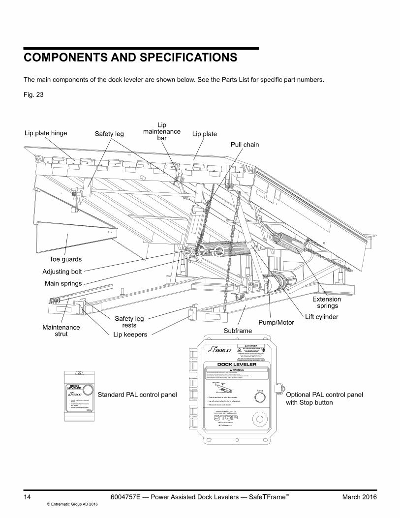
INTRODUCTIONWelcome and thank you for choosing this dock leveler from Serco.
This User’s Manual contains information that you need to safely install, operate and maintain the dock leveler. It also contains a complete parts list and information about ordering replacement parts. Please keep and read this User’s Manual before using your new dock leveler.
This dock leveler may be equipped with the optional ENERGY GUARD® dock leveler sealing system.
You may find safety signal words such as DANGER, WARNING, CAUTION or NOTICE throughout this User’s Manual. Their use is explained below:
Indicates an imminently hazardous situation which, if not avoided, will result in death or serious injury.
Indicates a potentially hazardous situation which, if not avoided, could result in death or serious injury.
Indicates a potentially hazardous situation which, if not avoided may result in minor or moderate injury.
Notice is used to address practices not related to personal injury.
This is the safety alert symbol. It is used to alert you to potential personal injury hazards. Obey all safety messages that
follow this symbol to avoid possible death or injury.
Introduction .................................................................2Safety Signal Words ...................................................2Safety Practices..........................................................3Owner’s Responsibilities ............................................4 Ramp and Lip Grades. ...............................................5Installation ..................................................................6Service tools ............................................................13Components and Specifications ...............................14Hydraulic System Operation .....................................15Operations Introduction ..........................................................16 Raising Leveler ....................................................17 Storing Leveler .....................................................18 Below Dock End Loading ....................................18 Power Loss .........................................................19
TABLE OF CONTENTS
SAFETY SIGNAL WORDS
Preventive Maintenance ...........................................20Adjustments Lip Assist with Lip Latch ......................................23Main Spring Counterbalance. ...................................25 Hydraulic Power Unit ...........................................26Hydraulic Schematic .................................................27Troubleshooting Guide .............................................28Electrical Schematic ................................................31Parts List...................................................................34Warranty ...................................................................47Corporate Contact ....................................................48
Read these Safety Practices before installing, operating or servicing the dock leveler. Failure to follow the safety practices could result in death or serious injury.
If you do not understand the instructions, ask your supervisor to explain them to you or call local Serco® distributor.
OPERATIONUse restricted to trained operators.
Follow procedures on placard posted near dock leveler.
Do not use this unit to service vehicles outside its intended working range which is 12" above and 12" below dock on 6' and 8' long levelers and 15" above and 12" below dock on 10' long levelers.
Do not operate the dock leveler with equipment, material or people on the ramp or lip.
Do not operate the dock leveler when anyone is in front of it unless they are securing the maintenance strut.
Stay clear of the dock leveler when it is moving.
STAY CLEAR OF HINGES AT ALL TIMES. Do not use hands to position dock leveler ramp or lip in vehicle or to store dock leveler.
Stay clear of leveler unless lip supported by the vehicle bed or the ramp is supported by both lip keepers; unsupported leveler can lower unexpectedly. Inspect leveler prior to use. Do not use if operating instructions placard or other parts are missing, leveler looks broken or damaged or does not seem to work right, and tell your supervisor leveler needs repair right away.
Do not stand in the driveway between the dock leveler and a backing vehicle.
Before chocking wheels or engaging vehicle restraint, dump air from air ride suspensions and set parking brakes.
Chock vehicle wheels or lock vehicle in place with a vehicle restraining device and set brakes before loading or unloading.
OPERATION (continued)Ensure lip avoids contact with vehicle sides and cargo. If lip does not lower to vehicle bed, reposition vehicle.
Do not use a fork truck or other material handling equipment to lower the ramp.
Move all equipment, material or people off dock leveler and store dock leveler at dock level before allowing the vehicle to pull out.
Store dock leveler at dock level after below dock end loading.
INSTALLATION, MAINTENANCE AND SERVICEService of dock leveler restricted to trained personnel.
If the dock leveler does not operate properly using the procedures in this manual, call your local distributor for service.
Place barricades on the dock floor around the dock leveler pit and in the driveway in front of the pit while installing, maintaining or repairing the dock leveler.
Do not operate the dock leveler when anyone is in front of it unless they are securing the maintenance strut.
Do not enter pit or do any maintenance or repair under dock leveler unless leveler is securely supported by maintenance strut.
Disconnect the power and properly tag or lock off before climbing into the dock leveler pit or doing any maintenance or repair under the dock leveler.
All electrical troubleshooting or repair must be done by a qualified technician and must meet applicable codes.
Disconnect the power and properly tag or lock off before doing any electrical work.
If it is necessary to make troubleshooting checks inside the control box with the power on, USE EXTREME CAUTION! Do not place fingers or uninsulated tools inside the control box. Touching wires or other parts inside the control box could result in electrical shock, death or serious injury.
OWNER’S RESPONSIBILITIESThe owner should recognize the inherent danger of the interface between dock and transport vehicle. The owner should, therefore, train and instruct operators in the safe use of dock leveling devices, and take appropriate steps to prevent their use by untrained individuals. Further information regarding selecting and training operators can be found in ANSI MH30.1 available at www.mhi.org/lodem. The owner shall verify the manual(s) containing the manufacturer's installation, operation, and maintenance, is made available for instruction and training personnel entrusted with such responsibilities.
When a transport vehicle is positioned as closely as practicable to a dock leveling device, there shall be at least 4" of overlap between the front edge of the lip and the edge of the floor or sill of the transport vehicle.
Manufacturer’s recommended periodic maintenance and inspection procedures in effect at date of shipment shall be followed, and written records of the performance of these procedures should be kept. Only trained and authorized personnel shall be permitted to maintain, repair, inspect and adjust the dock leveler. Use only original equipment manufacturer parts, manuals, maintenance instructions and labels; or their equivalent.
Dock leveling devices that are structurally damaged or have experienced a sudden loss of support while under load, such as might occur when a transport vehicle is pulled out from under the dock leveling device, shall be removed from service, inspected by the manufacturer’s authorized representative, and repaired as needed or recommended by the manufacturer before being placed back into service.
The owner shall see that all nameplates, cautions, instructions, and posted warnings are in place and legible and shall not be obscured from the view of operating or maintenance personnel for whom such warnings are intended.
Modifications or alterations of dock leveling devices shall be made only with written permission of the original manufacturer.
When industrial vehicles are driven on and off transport vehicles during the loading and unloading operation, the brakes on the transport vehicle shall be applied, and whenever possible, air-ride suspension systems should have the air exhausted and wheel chocks or positive restraints that meet the requirements of ANSI MH30.3 shall be engaged. For more detailed information regarding vehicle restraints see "ANSI MH30.3 Vehicle restraining devices: Performance and Testing" available at www.mhi.org/lodem.
The dock leveler should never be used outside its vertical working range or vertical lifting range or outside the manufacturer’s labeled rated capacity. It must also be compatible with the loading equipment and other conditions relating to the dock.
PIT CHECK1. Inspect the pit and remove all loose trash and construction
debris. Prepare the rear of the pit for the leveler mounting feet. Using a chisel, remove any high spots visible within 6" of the rear wall below the rear curb angle. Verify that the pit matches the pit details for your leveler. (Reference publication 826-001). See the Installation Troubleshooting section if the pit varies from the specification.
LEVELER CHECK PRIOR TO INSTALLATION1. Visually check that the 4 rear hinge pins and retaining
clips are in place.
2. Visually check that the lip pin retainers are in place on both ends of the lip rod.
3. Visually check that both the lip maintenance bar and maintenance strut are undamaged and pins securely attached.
4. Visually check that the foot assemblies at the rear of the leveler are in place and undamaged.
INSTALLATION OF DOCK LEVELER
Place barricades around pit on dock floor and drive while installing, maintaining or repairing dock leveler.
For AC applications, power to control box must be from fused disconnect supplied by others. Fuse size for a dual element motor protected time delay type fuse can be no greater than 225% of motor FLA. Before doing any electrical work, make certain the power is disconnected and properly tagged or locked out. All electrical work must be done by a qualified technician and must meet all applicable codes. If it is necessary to make troubleshooting checks inside the control panel with the power on, USE EXTREME CAUTION. Do not place fingers or uninsulated tools inside the control panel. Touching wires or other parts inside the control panel could cause electrical shock, death or serious injury.
Fig. 1
Fig. 2 — (see page 31-33 for pump/motor connections)
Before installing the dock leveler, read and follow the Safety Practices on Page 3. Failure to follow the safety practices could result in death or serious injury.
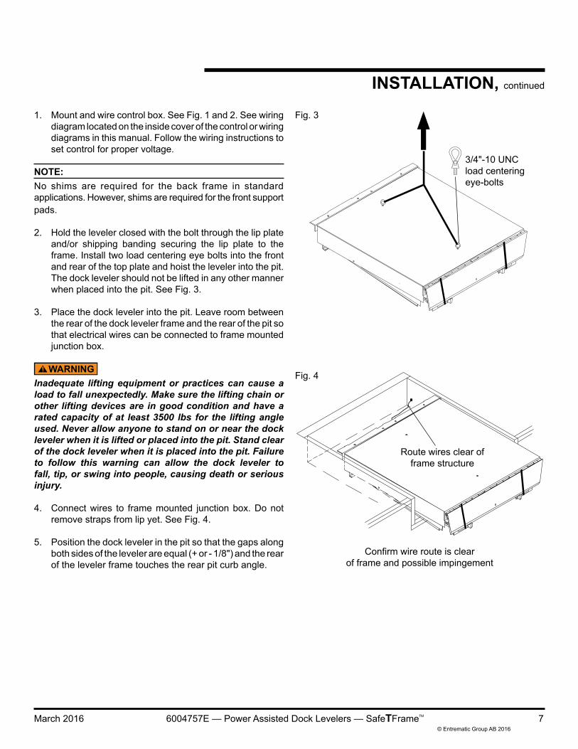
1. Mount and wire control box. See Fig. 1 and 2. See wiring diagram located on the inside cover of the control or wiring diagrams in this manual. Follow the wiring instructions to set control for proper voltage.
NOTE:No shims are required for the back frame in standard applications. However, shims are required for the front support pads.
2. Hold the leveler closed with the bolt through the lip plate and/or shipping banding securing the lip plate to the frame. Install two load centering eye bolts into the front and rear of the top plate and hoist the leveler into the pit. The dock leveler should not be lifted in any other manner when placed into the pit. See Fig. 3.
3. Place the dock leveler into the pit. Leave room between the rear of the dock leveler frame and the rear of the pit so that electrical wires can be connected to frame mounted junction box.
Inadequate lifting equipment or practices can cause a load to fall unexpectedly. Make sure the lifting chain or other lifting devices are in good condition and have a rated capacity of at least 3500 lbs for the lifting angle used. Never allow anyone to stand on or near the dock leveler when it is lifted or placed into the pit. Stand clear of the dock leveler when it is placed into the pit. Failure to follow this warning can allow the dock leveler to fall, tip, or swing into people, causing death or serious injury.
4. Connect wires to frame mounted junction box. Do not remove straps from lip yet. See Fig. 4.
5. Position the dock leveler in the pit so that the gaps along both sides of the leveler are equal (+ or - 1/8") and the rear of the leveler frame touches the rear pit curb angle.
Fig. 3
3/4"-10 UNCload centeringeye-bolts
Fig. 4
Route wires clear offrame structure
Confirm wire route is clearof frame and possible impingement
NOTE:The rear frame angle should be about 3/4" lower than the pit curb angle. This is normal. See Fig. 6.
6. To level the rear frame, use a 1/2" square drive (1/2" ratchet or impact tool). Work from one side to the other. Turn each of the leveling screws on the rear angle, counter clockwise until the top surface of the rear angle is level with the rear pit curb angle. Repeat on each screw until all feet are in contact with the pit floor and the top frame angle is flush with the rear curb angle. See Fig. 7.
Welding with the dock leveler’s power connected can damage electrical components. If the dock leveler has previously been electrically connected, turn off power to the control box and disconnect all dock leveler electrical wires from junction box on leveler frame before welding. Ground welder to dock leveler frame. Failure to do so can result in product damage.
7. Verify placement of the leveler in the pit is such that the rear frame angle is touching the rear pit curb angle and the gaps along both sides of the leveler are equal (+ or - 1/8")
The rear edge of the dock leveler should be level or slightly (1/16" max.) below dock level. NOTE:If the pit is out-of-square, the resulting gap between the rear frame and the rear curb angle should be shimmed as necessary. Use steel shim(s) and weld in place. See Installation Troubleshooting on page 12.
8. Tack weld the rear angle in place in 4 places min. 3/8", at or near each leveling screw. See Fig. 8.
NOTE:Do not drag leveler out of pit with legs extended. Do not do anymore than tack welds on the rear angle until after setting the front lip keepers.
Fig. 5
Fig. 63/4"
Fig. 8
Fig. 7
Raisesrearangle
Legadjustment
Raisesrearangle
Legadjustment
Legs are in contact with pit floor when the leveling screws are flush with the top of the transition angle
Shim under subframeTubes or lip keepers if fitted.
(Shims – 4" x 4" x height)
Shim under maintenance strut
1/4"
INSTALLATION, continued
NOTE:The top surface of the dock leveler should be level and a smooth transition with the dock floor curb angle. The front end should be level and parallel with the rear frame angle for proper operation. Unequal shimming of the front supports may be required to obtain a level front edge.
9. Remove and discard the shipping tie down straps located at the front hinged lip assembly. See Fig. 5.
Before welding the rear frame, cover the weather seals with a sheet of steel to prevent setting fire to the weather seals. Failure to do so may result in property damage.
Welding with the dock leveler’s power connected can damage electrical components. If the dock leveler has previously been electrically connected, turn off power to the control box and disconnect all dock leveler electrical wires from junction box on leveler frame before welding. Ground welder to dock leveler frame. Failure to do so can result in product damage.
Be certain that the rear hinge assembly is held tightly against the rear pit curb angle before welding.
If front and rear pit curb angles are not parallel do not attempt to shim dock leveler supports to match pit angles. The lip keepers and lip plate must be parallel for proper operation of the dock leveler. Add or subtract shims as required.
NOTE:Shims must be placed under the maintenance strut bracket and behind the lip keepers on 18" and 20" lips, shims must also be welded in between the lip keepers and the vertical face of the curb angle.
10. Position the dock leveler level with the dock floor. Use 4" x 4" shims to shim under the subframe tubes behind both lip keepers and under the maintenance strut bracket. See Fig. 9. These shims should be flush with the front of the leveler frame below or behind the lip keepers. Ensure the leveler is level with the finished floor.
11. Verify that the reflex leg roller is properly aligned. See Fig. 10. Reposition subrafme tube and shims as needed.
12. Tack weld the front subrame tubes and shims to the front curb angle as shown in Fig. 9.
13. Place leveler securely on the maintenance strut. If electrical power is available, use the electrical controls to raise the ramp and lip to their full above dock position. See operating instructions in this manual. If electrical power is not available, use a chain or other suitable lifting device. Refer to page 13 for proper procedure for using the maintenance strut.
Hydraulic pressure or mechanical support must be maintained on the ramp to hold it in the raised position until the maintenance strut is in place. DO NOT WORK UNDER THE DOCK LEVELER RAMP OR LIP UNLESS THE MAINTENANCE STRUT IS SECURELY SUPPORTING THE LEVELER (See page 13). NOTE:If the pit width conforms to the certified pit drawing, there will be a 1/8" gap between the ends of the dock leveler's rear frame angle and the pit side curb angles. If this is not the case, the ends of the rear frame angle may require trimming to allow the gaps along both sides of the leveler to be equal (+ or - 1/8").
14. Finish weld the rear hinge to the rear curb angle using 1/4" “V” joint in the grooves provided. Follow weld size and location noted in Fig. 11.
15. Finish weld shims under the maintenance strut bracket and under the subframe tubes behind the lip keepers with 3" min. long fillet welds in 3 places each. For 18" or 20" lips, also weld shims between the lip keepers and the vertical face of the front curb angle with 1/4" fillet welds.
16. After the rear frame angle is welded, check that all leveling feet are in contact with the floor of the pit. Once all feet are in contact with the floor, torque each leveling screw to 25-40 ft.-lbs. See Fig. 7.
17. Remove shipping cotter pins from telescopic toe guards (if equipped). See Fig. 13.
2 model B410-14* laminatedbumpers standard with eachleveler
*Flat end section to bewelded to angle
3/8" Typ
Vertical downwelds not acceptable
Fig. 15
Fig. 16Optionalcap plug
Rear angle
INSTALLATION, continued
18. Mount dock bumpers to face of dock. See Fig. 14.
19. Read Safety Practices on page 3 and Operating Instructions on pages 16-19. With electrical power available, use the controls to operate the dock leveler through the complete cycle to check operation. Ensure leveler operates properly.
20. Permanently mount the laminated dock leveler safety placard on the wall near the dock leveler controls. Make sure the customer gets the user’s manual and is properly trained. See Fig. 15.
Keep hands, fingers and head away from the lip when the raise button is released. The lip and dock leveler are free to move downward when hydraulic pressure is removed from cylinders.
21. Operate the dock leveler four more times through the complete cycle to check operation.
22. Where applicable, install rear angle cap plugs (part number 6004488) into adjustment socket holes. Use hammer to drive cap flush with top surface to rear angle. See Fig. 16.
ACTUATION ROD WALL MOUNT ASSEMBLY23. Anchor wall mount bracket to dock wall approximately as
PROBLEM POSSIBLE CAUSE SOLUTION1) Leveler will not fit properly in pit. a) Pit is out of square with the sides.
b) One side and rear angle is out of square.
c) Pit floor irregular in rear.
d) Pit is too deep.
a) Align the sides of the leveler so that both sides are equal (+ or - 1/8"). With the leveler's rear frame angle touching the rear curb angle, any gaps between the frame and the rear curb angle must be filled with steel shims of appropriate thickness and length equal to the frame's beveled weld locations. See Fig 17.
b) If the gap between the leveler and the side of the pit is less than 1/2" at any point, the performance of the leveler may be impaired - especially if weatherseal is attached to the leveler. Please consult Entrematic Technical Services should this be the case.
c) If large deformations exist in the concrete work, attempt to flatten out the rough surface using a chisel or grinder to take out the large obstructions. The rear leveling legs can be installed on out of plane surfaces up to 1/8" at each leg. See Fig. 19.
d) Weld 4" x 4" shims to the bottom of the adjustable legs as shown in Fig 3.
INSTALLATION TROUBLESHOOTINGThe following procedures apply after the leveler is level in the pit.
Shim and weld
1/8" MAXallowable stepno greater than1" x 3" in size
Be certain, before climbing into the dock leveler pit or doing any maintenance or repair under the dock leveler, that THE MAINTENANCE STRUT IS SECURELY SUPPORTING THE DOCK LEVELER.
Before servicing the dock leveler, read and follow the Safety Practices on page 3 and the operation section of this manual.
MAINTENANCE STRUT1. To raise the maintenance strut two people are needed:
a. Push and hold the RAISE button on the control panel so leveler is fully raised.
b. Second person can pull on the strut and lift the end up.
c. Push down on the maintenance strut to lock it in its vertical position.
d. Release the RAISE button.
2. To lower the maintenance strut from its locked upright position two people are needed:a. Push and hold the RAISE button on the control
panel.
b. Second person slides maintenance strut up to unlock from the vertical position.
c. Push back to lower the maintenance strut.
d. Release the RAISE button.
LIP MAINTENANCE BAR1. To raise the lip maintenance bar:
a. Support the lip manually and swing up the lip maintenance bar so the lip will rest on it. Ensure the strut is wedged in properly before releasing the lip. See Fig. 21.
2. To release the lip maintenance bar:a. Support the lip manually and pull the lip maintenance
bar down. LIP WILL DROP with out manual support. Ensure your head and fingers are away from the lip and any moving parts.
Control Panel - NEMA 4, 120V, 1 Phase, 60 Hz or 24V DC.
Motor - NEMA Standard T.E.N.V. / 48 YZ frame, 1/3 h.p., single.
Pump - Fixed displacement gear pump, 0.4 gpm @ 1800 rpm, primary relief valve factory set at 900 psi.
Reservoir Capacity - .33 U.S. gal., (1.25 L)
Hydraulic Fluid - An all weather hydraulic fluid with a viscosity of 15 CSt at 40°C (100°F), such as:
Shell Tellus T 15 Mobil Aero HFA (49011) Exxon Univis: HV13, N15, J13 Texaco Aircraft Oil #1554 U.S. Oil Co.,Inc #ZFI-5606 (Low Temp.)
RAISEPress in• Pump starts and cylinder starts to raise leveler.Release• Pump stops and cylinder retracts to lower leveler.
STOP BUTTON (Optional)Press in• Solenoid valve shifts, locking hydraulic cylinder.• Power is cut off from motor circuit.• Leveler is held in position by hydraulic cylinder as
long as STOP button is held in.
NOTE:DO NOT DRIVE ON LEVELER WITH THE STOP BUTTON ENGAGED.
The following describes the operation of the hydraulic system when the control is activated:
Before operating the dock leveler, read and follow the Safety Practices on page 3.
Use of dock leveler restricted to trained operators.
Follow procedures on placard posted near dock leveler.
Inspect leveler prior to use. Do not use if operating instructions placard or other parts are missing, leveler looks broken or damaged or does not seem to work right, and tell your supervisor leveler needs repair right away.
Before pressing button, ensure lip avoids contact with trailer sides and cargo. If lip does not lower to vehicle bed, reposition vehicle.
Stay clear of leveler unless lip is supported by vehicle bed or the leveler is stored at dock level. Visually check that the lip is supported by the vehicle bed or the ramp is supported by both lip keepers or safety legs before driving or walking on the ramp. Unsupported dock levelers can lower unexpectedly.
Before chocking wheels or engaging vehicle restraint, dump air from air ride suspensions and set parking brakes.
Always be certain that the vehicle wheels are chocked, or that the vehicle is locked in place by a vehicle restraining device and the brakes are set before loading or unloading. Vehicles pulling away from the dock unexpectedly can cause uncontrolled drop of the dock leveler which can result in death or serious injury.
The maximum uncontrolled drop of a Serco PAL leveler, from 3-1/4" above dock is to the safety legs (slightly below dock level), or if below 3-1/4" above dock the leveler will drop to the full below dock position.
Always return the dock leveler to its dock level (stored) position before allowing the vehicle to leave the dock. If the vehicle pulls away from the dock before the dock leveler is stored, the lip will fall to its pendant position and the ramp will drop. In addition, failure to properly store the leveler may leave the leveler in a position below the level of the dock floor. This condition may result in unexpected drop of personnel or material handling equipment and result in death or serious injury.
Failure to follow these instructions could result in death or serious injury to operators and/or bystanders.
INTRODUCTIONThe Serco PAL dock leveler is designed to span and compensate for space and height differences between a loading dock and freight carrier to allow safe, efficient freight transfers.
The Serco PAL dock leveler uses a push-button control to position the ramp. Pushing and holding the RAISE button operates a hydraulic cylinder to raise the ramp. Releasing the RAISE button allows the ramp to lower.
A mechanical linkage extends the dock leveler lip as the ramp is being raised from its stored position, and the leveler with its lip extended settles onto the vehicle bed forming a bridge.
After loading pressing and holding the RAISE button allows the ramp to raise. The lip will retract as the leveler is raised. Releasing the RAISE button lowers the ramp into its level, stored position.
With the dock leveler in its stored position, Lip Keepers support the dock leveler ramp at a position level with the dock floor.
For below dock end loads the lip can be extended beyond the lip keepers by pulling the below dock chain, located at the left front side of the deck before the deck lowers past dock level.
In the event of power failure the leveler can still be operated using a manual activation rod which is shipped with the dock leveler and should be stored nearby.
Do not drive on dock leveler or lip until it is fully extended and supported by the vehicle bed.
Never use a fork truck or other material handling equipment to lower the ramp and lip sections.
RAISING LEVELEREnsure a vehicle restraining device is engaged or wheel chocks in place before operating the dock leveler.
1. Press and hold the RAISE button on control panel to raise the leveler. See Fig. 25.
2. Continue to hold the raise button. When the leveler is fully raised, the lip will automatically extend. See Fig. 26.
3. When the lip is fully extended, release the RAISE button. The leveler will slowly float down to the vehicle bed. If the leveler is equipped with the optional Stop, push the STOP button at any time to stop the leveler. Pull the leveler STOP button to resume operation.
Never drive on dock leveler with STOP button pressed.
Before allowing vehicle to leave always return the dock leveler to its dock level (stored) position with the lip stored in both lip keepers. See Fig. 28. Failure to do so may leave the dock leveler in a position below the level of the dock floor. This condition may result in unexpected drop of personnel or material handling equipment and could result in death or serious injury.
STORING LEVELER1. To return the leveler to the stored position, press and
hold the RAISE button. As the leveler raises the lip will retract. When the lip is fully retracted, release the RAISE button. The leveler will float down to the stored position. See Fig. 28.
BELOW DOCK END LOADING1. Press and hold the RAISE button until leveler is
partially raised, release button and then pull the below dock chain to extend the lip beyond the lip keepers. Leveler will float down for end loading. See Fig. 29.
5. Inspect the lip push out arm and lip counterbalance assemblies for damage and check the chain and springs for elongation. Inspect lip latch adjustment as per procedures on pages 23-24, make adjustments as necessary.
6. Inspect all welds under the leveler for fatigue or failure, particularly the lip plate hinge and top plate beams and front hinge bar.
7. Check the full operation of the leveler. Make any adjustments required.
8. Lubricate the lip hinge tubes with molybdenum disulfide grease NLGI #2. Do not over grease. Stop when grease begins to ooze out of the hinge tube ends. Wipe off excess grease. See Fig. 32 on page 21.
9. Inspect the hydraulic cylinder and hose for any fluid leaks and check reservoir level with the leveler resting on the maintenance strut, add fluid as required. See Hydraulic Fluid Level on page 256.
10. Inspect dock bumpers. Four inches (4") of bumper protection is required. Worn, torn, loose or missing bumpers must be replaced.
NOTE:See Fig. 32 on page 21 for lubrications points.
Be certain, before climbing into the dock leveler pit or doing any maintenance or repair under the dock leveler, that: 1) THE MAINTENANCE STRUT is securely supporting the leveler and the power is disconnected and properly tagged or locked out.
Before servicing the dock leveler, read and follow the Safety Practices on page 3 and the operation section of this manual.
Place barricades on the dock floor around the dock leveler pit and in the driveway in front of the pit while installing, maintaining or repairing the dock leveler.
WEEKLY
1. Inspect for debris in lip hinge. Clean as required.
2. Inspect for debris in rear hinge area of the leveler and between the sides and curb angles to ensure smooth operation. Clean as required. Inspect the safety leg system for free operation, structural defects, pull chain and return spring operation.
3. Inspect the operation of the telescopic toe guards to ensure they are not distorted or binding when operating the leveler.
4. Check the full operation of the leveler to ensure that there is no hesitation in the hydraulic system.
QUARTERLY
1. Inspect all warning labels and placards. See page 22. Replace as necessary.
2. Clean away any debris from the rear hinge and pit area. If washing out, take care not to direct spray at any electrical parts.
3. Inspect and lubricate all mechanical pivot points on the leveler with a light oil such as S.A.E. 30. See Fig. 32 on page 21.
4. Raise and then lower the leveler down to full below dock position with the lip extended. Ensure that the latch bar will disengage and the lip will fall to the pendant position automatically. (See pages 23-24 for adjustment)
WARNING AND OPERATION PLACARD(MOUNTED ON WALL NEAR LEVELER)
OPERATING INSTRUCTIONS
PREVENTIVE MAINTENANCE, continued
Every 90 days (quarterly) inspect all safety labels and tags to ensure they are on the dock leveler and are easily legible. If any are missing or require replacement, please call your local Serco distributor for replacements.
Always make sure that the maintenance strut is securely supporting the leveler in the raised position before working under a dock leveler. See page 13.
1) Always position traffic cones or a barricade behind and in front of the dock leveler to warn fork truck operators, vehicle traffic and pedestrians away from the dock leveler.
2) Always notify a foreman or supervisor that you are working under the equipment.
LIP LATCH ADJUSTMENT
Fig. 34
NOTE:Hydraulic or main spring assemblies not shown. No adjustment required to hydraulic or main spring assemblies for this application.
The lip spring acts through the bell crank and the lip assist bar to counter balance the weight of the lip. The lip spring is attached by two chains to both the deck and to the frame. The upper chain to the deck maintains a minimum tension force in the spring to partially counter balance the lip. The lower chain is attached to the frame and provides an additional tension force that increases as the deck is raised. This increased spring force will fully counter balance the weight of the lip as it is rotated to the extended position. The lip latch bar will be in the engaged (lowered) position but the weight of the lip will be fully supported by the lip spring.
As the deck lowers with the lip extended, the lower chain slackens and the lip spring tension is reduced. When the lip and deck have lowered ten inches from the highest position, the lip must fall on to the lip latch to hold the latch in the engaged position. When leveler is lowered to the working height (approx. 12" above dock) the lower chain will be slack and the upper chain will tighten and extend the lip latch release spring. As long as the lip is resting on the lip latch the latch will not release. When the lip is supported by the bed of a vehicle, the release spring will rotate the latch release bar and raise the latch bar to the released position. When the leveler is raised, or the vehicle leaves, the lip will then fall to the stored position.
LIP LATCH AND LIP SPRING ADJUSTMENT
NOTE:A remote, normally open push-button service switch is required to perform the following steps. If this switch is not available, two people are required for the following steps. One person must remain at the control panel while the other is adjusting the dock leveler.
1. Fully raise the leveler, extend the lip and raise the maintenance strut. Lower the deck to rest on the raised maintenance strut. Raise the lip maintenance support to prevent the lip from falling. Check that the lip latch bar has locked into position. Lubricate all pivots with S.A.E. 30 oil and lip hinge tubes with general purpose grease.
2. If the lip does not fully extend, check for binding of the latch bar, debris in the lip hinge, or improper attachment of the lip chain and lip spring. There are three holes in the lip latch bar. The lip chain is normally attached to the middle hole. If the chain is attached to the front hole leave it there. If the chain is attached to the middle hole and the lip has been properly cleaned and lubricated and will not start to extend, move the chain to the front hole.
3. With the maintenance strut still raised, press the RAISE button until the leveler is fully raised. The lip should be held extended by the lip spring and the lip latch should be free to move. If the lip is resting on the lip latch, increase the tension of the lip spring by turning the adjusting bolt clockwise.
4. When the RAISE button is released and the leveler is being lowered, the lip spring tension will be reduced. The lip must fall on to the lip latch within 10 inches from the fully raised position. If the lip does not fall onto the latch bar, reduce tension of the lip spring by turning the adjusting bolt counter-clockwise. There may be very little movement of the lip when it falls on to the lip latch. The movement can be seen more easily by watching the gap between the rear edge of the lip and the front edge of the deck.
5. Raise the leveler and lower the maintenance strut and the lip maintenance support. Allow the leveler to lower. As it reaches the working height, the upper chain will tighten and extend the lip latch release spring. Lifting up on the end of the lip will allow the lip latch to release, and the lip will fall when it is released.
6. The operation of the lip latch and release can be further tested by using a sturdy post cut to the length of the dock height plus 10 inches. Raise the dock leveler, extend the lip and lower the leveler so that the end of the lip is resting on the post. Then raise the leveler again. As the leveler is raised, the lip should fall to the stored position.
NOTE:Adjusting of the main spring cylinder on the PAL leveler is normally never required. In the unlikely event it does need to be done, use the following procedure. Before adjusting the main spring:
1. Make sure that the hydraulic system has proper oil level. See Page 26. Low oil level may cause the leveler to raise too slowly.
2. Make sure that the lip hinge is lubricated and is operating freely. Excessive friction in the lip hinge may prevent the lip from raising easily.
Extended springs contain stored energy. Never attempt to remove main springs without completely removing the load from the springs first. Do not remove the main springs until the leveler and the lip are securely supported by a suitable lifting device.
Fig. 35
Tools Required: 1-1/2 inch wrench
1. With the lip extended and the leveler near dock level, approximately 50 to 70 pounds should be required at the end of the lip to support the dock leveler.
2. To adjust the main spring, raise the leveler, raise the maintenance strut and rest the leveler on the maintenance strut.
3. To decrease the weight of the dock leveler, turn the adjusting nut clockwise. To increase the weight of the dock leveler, turn the adjusting nut counter-clockwise.
4. Lower the maintenance strut and lower the dock leveler to dock level. Re-check the weight of the leveler and adjust as required.
Turn off electrical power at source or switch off circuit breaker in the control panel to prevent accidental operation while making adjustments.
Do not enter the leveler pit unless the leveler is securely supported and barriers are in place.
Part NumberBreather cap
Reservoir
motorRelief valve
Fig. 36
Description Purpose Adjustment
Relief Valve Controls maximum pressure in the hydraulic system and protects the other components from excessive force. Relief pressure is factory set at 900 PSI and should not require adjustment.
(A pressure gauge is necessary)Loosen jam nut – counterclockwise, turn screw clockwise to increase pressure and counterclockwise to decrease pressure, tighten jam nut to 50 in-lb torque. Check pressure after jam nut is tight and readjust if necessary.
Integral Shuttle Valve Directs fluid to the cylinder when the pump is running. Prevents fluid from returning to reservoir when valve is in on position and power failure occurs.
No adjustment required.
Hydraulic Fluid LevelThe hydraulic fluid level should be checked when the leveler is resting on the maintenance strut. The fluid level in reservoir should be approximately 1/2 full. See Fig. 37. If the level is low, fill to the halfway point using an approved oil from the list on page 15.
TROUBLESHOOTING GUIDEUse the Troubleshooting Guide if ever the leveler fails to perform properly. Find the condition that most closely matches your situation, and make the recommended adjustments.
Be certain, before climbing into the dock leveler pit or doing any maintenance or repair under the dock leveler, that the maintenance strut is raised and securely supporting the dock leveler in case of emergency.
Problem Possible Cause Solution
1. Leveler does not raise, motor is silent.
a) No electrical power to control panel.
b) Electrical connections incorrect or broken.
a) Check that voltage is present at terminal connections to the control panel.
b) Check that wiring matches the wiring diagram.
2a. Leveler does not raise; motor starts then stops, motor starter relay chatters.
a) Overload relay, main circuit breaker or leveler control circuit breaker tripping out.
b) Voltage drop due to long wiring distance from power source.
a) Check overload setting and current draw.
b) Check voltage when motor is started. Voltage drop is more often a problem on single phase motors. See conductor specifications in installation instructions.
2b. Leveler does not raise. Motor hums.
a) Voltage drop. a) See above.
2c. Leveler does not raise. Motor runs.
a) Low fluid level in reservoir.
b) Pump not running or pressure insufficient.
c) Primary relief valve setting too low.
a) Check fluid level with leveler fully raised. Add fluid if required and check for leaks.
b) Remove the hose from main lift cylinder and point free end into reservoir opening. If no oil is pumped, check pump drive shaft coupler or replace pump.
c) Set primary relief valve setting to 900 PSI. See page 26.
Before servicing the dock leveler, read and follow the Safety Practices on page 3 and the Operating Instruction section in this manual.
Failure to do so could result in death or serious injury.
Before doing any electrical work, make certain the power is disconnected and properly tagged or locked off. All electrical work must be done by a qualified technician and meet all applicable codes. If it is necessary to make troubleshooting checks inside the control box with the power on, USE EXTREME CAUTION. Do not place your fingers or uninsulated tools inside the control box. Touching wires or other parts inside the control box could result in electrical shock, death or serious injury.
To ensure proper function, durability and safety of the product, only replacement parts that do not interfere with the safe, normal operation of the product must be used. Incorporation of replacement parts or modifications that weaken the structural integrity of the product, or in a way alter the product from its normal working condition at the time of purchase from Serco® could result in product malfunction, breakdown, premature wear, death or serious injury.
Item Qty Description 30,000 35,000 40,000 45,000 50,000 43 1 LIP HINGE PIN - 6FT WIDE 586-0017 586-0017 586-0287 586-0287 586-0287 LIP HINGE PIN - 6.5FT WIDE 586-1494 586-1494 586-1495 586-1495 586-1495 LIP HINGE PIN - 7FT WIDE 586-0201 586-0201 586-0392 586-0392 586-0392 44 1 LIP ASSEMBLY: 6 FT X 16 IN 30845 30848 30851 30854 30857 LIP ASSEMBLY: 6 FT X 18 IN 30846 30849 30852 30855 30858 LIP ASSEMBLY: 6 FT X 20 IN 30847 30850 30853 30856 30859 LIP ASSEMBLY: 6.5 FT X 16 IN 30863 30866 30869 30872 30875 LIP ASSEMBLY: 6.5 FT X 18 IN 30864 30867 30870 30873 30876 LIP ASSEMBLY: 6.5 FT X 20 IN 30865 30868 30871 30874 30877 LIP ASSEMBLY: 7 FT X 16 IN 35487 35490 35493 35496 35499 LIP ASSEMBLY: 7 FT X 18 IN 35488 35491 35494 35497 35500 LIP ASSEMBLY: 7 FT X 20 IN 35489 35492 35495 35498 35501 LIP ASSEMBLY: 6.5 FT X 16 IN (3" TAPER) 33645 33648 33651 33654 33657 LIP ASSEMBLY: 6.5 FT X 18 IN (3" TAPER) 33646 33649 33652 33655 33658 LIP ASSEMBLY: 6.5 FT X 20 IN (3" TAPER) 33647 33650 33653 33656 33659 LIP ASSEMBLY: 7 FT X 16 IN (3" TAPER) 33663 33666 33669 33672 33675 LIP ASSEMBLY: 7 FT X 18 IN (3" TAPER) 33664 33667 33670 33673 33676 LIP ASSEMBLY: 7 FT X 20 IN (3" TAPER) 33665 33668 33671 33674 33677 LIP ASSEMBLY: 7 FT X 16 IN (3" ELLIPSE) 33707 33710 33713 33716 33719 LIP ASSEMBLY: 7 FT X 18 IN (3" ELLIPSE) 33708 33711 33714 33717 33720 LIP ASSEMBLY: 7 FT X 20 IN (3" ELLIPSE) 33709 33712 33715 33718 33721
Item Part Description 30,000 35,000 40,000 45,000 50,000 56* MAIN SPRING, EXT - 6 FT X 16 IN 333-049(3) 333-049(3) 333-049(3) 333-049(3) 333-049(3) MAIN SPRING, EXT - 6 FT X 18 IN 333-049(3) 333-049(3) 333-049(3) 333-049(3) 333-049(3) MAIN SPRING, EXT - 6 FT X 20 IN 333-049(3) 333-049(3) 333-049(3) 333-049(3) 333-049(3)
56* MAIN SPRING, EXT - 6.5 FT X 16 IN 333-049(3) 333-049(3) 333-049(3) 333-049(3) 333-049(3) MAIN SPRING, EXT - 6.5 FT X 18 IN 333-049(3) 333-049(3) 333-049(3) 333-049(3) 333-049(3) MAIN SPRING, EXT - 6.5 FT X 20 IN 333-049(3) 333-049(3) 333-049(3) 333-049(3) 333-054(2)
56* MAIN SPRING, EXT - 7 FT X 16 IN 333-049(3) 333-049(3) 333-049(3) 333-049(3) 333-054(2) MAIN SPRING, EXT - 7 FT X 18 IN 333-049(3) 333-054(3) 333-049(3) 333-049(3) 333-054(2) MAIN SPRING, EXT - 7 FT X 20 IN 333-049(3) 333-049(3) 333-049(3) 333-049(3) 333-054(2)
57 MAIN SPRING, SUPPORT ASSY - WL 6-800 3-5073(1) 3-5073(1) 3-5073(1) 3-5073(1) 3-5073(1)
Item Part Description 30,000 35,000 40,000 45,000 50,000 56* MAIN SPRING, EXT - 6 FT X 16 IN 333-054(2) 333-054(2) 333-054(2) 333-054(2) 333-054(2) 333-049(1)
MAIN SPRING, EXT - 6 FT X 18 IN 333-054(2) 333-054(2) 333-054(2) 333-054(2) 333-054(2) 333-049(1)
MAIN SPRING, EXT - 6 FT X 20 IN 333-054(2) 333-054(2) 333-054(2) 333-054(2) 333-054(2) 333-049(1)
56* MAIN SPRING, EXT - 6.5 FT X 16 IN 333-054(2) 333-054(2) 333-054(2) 333-054(2) 333-054(2) 333-049(1)
MAIN SPRING, EXT - 6.5 FT X 18 IN 333-054(2) 333-054(2) 333-054(2) 333-054(2) 333-054(2) 333-049(1)
MAIN SPRING, EXT - 6.5 FT X 20 IN 333-054(2) 333-054(2) 333-054(2) 333-054(2) 333-054(2) 333-049(1) 333-049(1) 333-049(1)
56* MAIN SPRING, EXT - 7 FT X 16 IN 333-054(2) 333-054(2) 333-054(2) 333-054(2) 333-054(2) 333-049(1)
MAIN SPRING, EXT - 7 FT X 18 IN 333-054(2) 333-054(2) 333-054(2) 333-054(2) 333-054(2) 333-049(1) 333-049(1) 333-049(1)
MAIN SPRING, EXT - 7 FT X 20 IN 333-054(2) 333-054(2) 333-054(2) 333-054(2) 333-054(2) 333-049(1) 333-049(1) 333-049(1)
57 MAIN SPRING, SUPPORT ASSY - WL 6-800 3-5073(1) 3-5073(1) 3-5073(1) 3-5073(1) 3-5073(1)
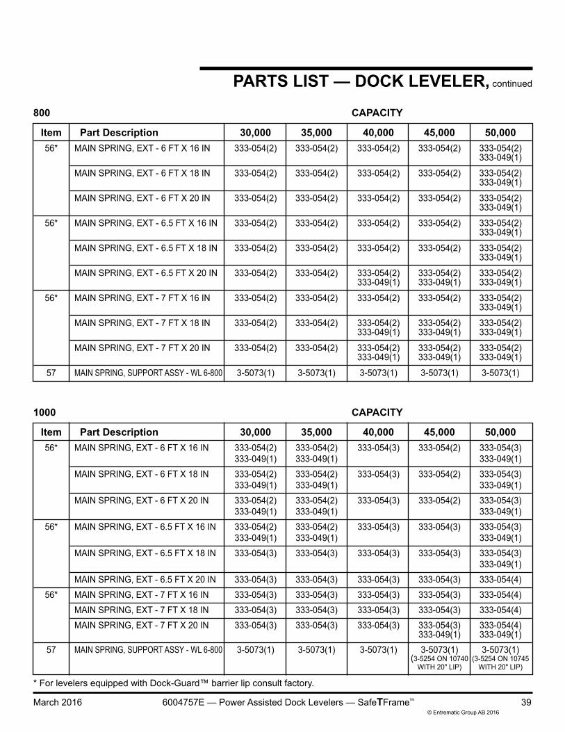
800 CAPACITY
Item Part Description 30,000 35,000 40,000 45,000 50,000 56* MAIN SPRING, EXT - 6 FT X 16 IN 333-054(2) 333-054(2) 333-054(3) 333-054(2) 333-054(3) 333-049(1) 333-049(1) 333-049(1) MAIN SPRING, EXT - 6 FT X 18 IN 333-054(2) 333-054(2) 333-054(3) 333-054(2) 333-054(3) 333-049(1) 333-049(1) 333-049(1) MAIN SPRING, EXT - 6 FT X 20 IN 333-054(2) 333-054(2) 333-054(3) 333-054(2) 333-054(3) 333-049(1) 333-049(1) 333-049(1) 56* MAIN SPRING, EXT - 6.5 FT X 16 IN 333-054(2) 333-054(2) 333-054(3) 333-054(3) 333-054(3) 333-049(1) 333-049(1) 333-049(1) MAIN SPRING, EXT - 6.5 FT X 18 IN 333-054(3) 333-054(3) 333-054(3) 333-054(3) 333-054(3) 333-049(1) MAIN SPRING, EXT - 6.5 FT X 20 IN 333-054(3) 333-054(3) 333-054(3) 333-054(3) 333-054(4) 56* MAIN SPRING, EXT - 7 FT X 16 IN 333-054(3) 333-054(3) 333-054(3) 333-054(3) 333-054(4) MAIN SPRING, EXT - 7 FT X 18 IN 333-054(3) 333-054(3) 333-054(3) 333-054(3) 333-054(4) MAIN SPRING, EXT - 7 FT X 20 IN 333-054(3) 333-054(3) 333-054(3) 333-054(3) 333-054(4) 333-049(1) 333-049(1) 57 MAIN SPRING, SUPPORT ASSY - WL 6-800 3-5073(1) 3-5073(1) 3-5073(1) 3-5073(1) 3-5073(1) (3-5254 ON 10740 (3-5254 ON 10745 WITH 20" LIP) WITH 20" LIP)
1000 CAPACITY
* For levelers equipped with Dock-Guard™ barrier lip consult factory.
LIMITED WARRANTYTHIS LIMITED WARRANTY IS ENTREMATIC’S SOLE AND EXCLUSIVE WARRANTY WITH RESPECT TO THE DOCK LEVELER AND IS IN LIEU OF ANY OTHER GUARANTEES OR WARRANTIES, EXPRESS OR IMPLIED
ENTREMATIC warrants that this DOCK LEVELER will be free from flaws in material and workmanship under normal use for a period of one (1) year from the earlier of 1) 60 days after the date of initial shipment by ENTREMATIC, or 2) the date of installation of the DOCK LEVELER by the original purchaser, provided that the owner maintains and operates the DOCK LEVELER in accordance with this User's Manual.
Main Spring Warranty — All main springs are warranted to cover the cost of replacement parts and freight only for an extended period of four (4) years after the initial 1 yr. warranty period.
Hydraulic Limited Warranty: The hydraulic power unit and cylinders for this dock leveler are warranted to cover the cost of replacement costs only for an extended period of four (4) years beyond the base warranty period.
Parts warranty — All spare or replacement parts are warranted to cover the cost of replacement parts and freight only for ninety (90) days from the date of shipment.
In the event that this DOCK LEVELER proves deficient in material or workmanship within the applicable Limited Warranty period, owner shall so notify ENTREMATIC, and ENTREMATIC will, at its option:
1. Replace the DOCK LEVELER, or the deficient portion(s) thereof, without charge to the owner; or
2. Alter or repair the DOCK LEVELER, on site or elsewhere, without charge to the owner.
This Limited Warranty does not cover any failure caused by improper installation, abuse, improper operation, negligence, or failure to maintain and adjust the DOCK LEVELER properly. Parts requiring replacement due to damage resulting from vehicle impact, abuse, or improper operation are not covered by this warranty. ENTREMATIC DISCLAIMS ANY RESPONSIBILITY OR LIABILITY FOR ANY LOSS OR DAMAGE OF ANY KIND (INCLUDING WITHOUT LIMITATION, DIRECT, INDIRECT, CONSEQUENTIAL OR PUNITIVE DAMAGES, OR LOST PROFITS OR LOST PRODUCTION) arising out of or related to the use, installation or maintenance of the DOCK LEVELER (including premature product wear, product failure, property damage or bodily injury resulting from use of unauthorized replacement parts or modification of the DOCK LEVELER). ENTREMATIC’s sole obligation with regard to a DOCK LEVELER that is claimed to be deficient in material or workmanship shall be as set forth in this Limited Warranty. This Limited Warranty will be null and void if the original purchaser does not notify ENTREMATIC’s warranty department within ninety (90) days after the product deficiency is discovered. .
THERE ARE NO WARRANTIES, EXPRESS OR IMPLIED, WHICH EXTEND BEYOND THE DESCRIPTION ON THE FACE HEREOF, INCLUDING, BUT NOT LIMITED TO, A WARRANTY OF MERCHANTABILITY OR OF FITNESS FOR A PARTICULAR PURPOSE, ALL OF WHICH ENTREMATIC HEREBY DISCLAIMS.
Your local Serco distributor is:
Please direct questions about your dock leveler to your local distributor or to Entrematic.
Corporate Head Office:
1612 Hutton Dr. Suite 140Carrollton, TX. 75006Tel. (972) 466-0707Fax (972) 323-2661