Contents lists available at SciVerse ScienceDirect
Applied Surface Science
journa l homepage: www.e lsev ier .com/ locate /apsusc
alladium nanoparticles on hierarchical carbon surfaces: A new architecture forobust nano-catalysts
ema Vijwani, Sharmila M. Mukhopadhyay ∗
enter for Nanoscale Multifunctional Materials, Wright State University, Dayton, OH 45435, USA
r t i c l e i n f o
rticle history:eceived 21 May 2012eceived in revised form 6 September 2012ccepted 9 September 2012vailable online 4 October 2012
eywords:alladiumetal nanoparticle
a b s t r a c t
Surface activity of heterogeneous catalysts can be enhanced if their sizes are reduced to nanometers. How-ever, loose nanomaterials pose potential health and environmental risks. This issue has been addressedby attachment of palladium nanoparticles on multi-scale hierarchical carbon supports that have excep-tionally high surface area per volume. The supports consist of porous carbon foam whose surface hasbeen either chemically functionalized, or morphologically altered by grafting of carbon-nanotubes. Itis seen that whereas chemical functionalization does provide some increase in nano-catalyst loading,morphological modification is significantly more powerful. It has the potential to create orders of mag-nitude increase in catalytic activity within the same overall volume. The synthesis techniques have been
investigated in sufficient detail to provide significant control over the density and size of nanoparticles.Abundant distribution of nanoparticles is observed even within the deeper pores of the microcellularfoam. The nanoparticles are seen to be metallic Pd having face centered cubic structure. Additionally, thenano-particles and nanotubes are durable, and remain attached to the base support after long periodsof rapid rotation in water. These robust hybrid structures show promise in future applications such as
n sys
sensors, water purificatio
. Introduction
Metal nanoparticles offer several unique properties related toize, shape and surface chemical activity [1,2]. These propertiesan enhance their performance as sensors and catalysts for cut-ing edge technologies applicable in bio-medicine [3,4], electronics5], environment [6], catalysis [7], optics and optical sensing [8].mong various transition and rare earth metals, palladium (Pd) isidely recognized as an important heterogeneous catalyst useful
n many reactions [9,10]. In addition to its catalytic activity, Pd hashe unique ability of absorbing hydrogen while being imperviouso other gases [11]. At room temperature and moderate pres-ure, hydrogen can readily diffuse into the metal lattice, therebyntroducing strain in the lattice and it coexists in both metallicnd metal-hydride phases simultaneously [12,13]. These proper-ies make Pd a very useful element in a wide range of applicationsuch as fuel cell catalysts [14], sensors [15], dechlorination catalysts16], and hydrogen storage media [17,18].
For surface dependent heterogeneous reactions, nano-size par-icles of precious metals can provide high surface-to-volume ratioesulting in higher catalytic activity per unit volume. Moreover,
the catalytic properties may change dramatically at nanoscaledimensions compared to their bulk counterparts resulting inunprecedented uses [19]. Nanocatalysts can be used as stand-aloneparticles, or often attached to larger supports. Nanoparticles (NPs),when used in isolated form tend to agglomerate, compromisingtheir reactivity. They are sometimes suspended in colloidal solu-tions by using surfactants, capping agents, or polymeric binders[1,20–23]. While these additives can stabilize the particles, theymay also coat the surface leading to reduced catalytic activity [1].
Supported metal NPs, on the other hand, may provide advan-tages in stabilizing the size without coating the surface. Thecommon materials that are adopted to support NPs include oxidessuch as silica and alumina; and carbon structures such as activatedcarbon and nanostructures of carbon [24–26]. The electronic prop-erties of the support are significant in that they can influence thecatalytic activity of the metal through specific metal-support inter-actions [27–30]. Strong metal–support interactions, often seen inoxide supports, may result in altered (often suppressed) catalyticactivity. Carbon based structures offer chemical inertness and weakmetal–support interaction, therefore may not suppress the chem-ical activity of the metal-surface [31]. Moreover, carbon supports,provide the benefits of high mechanical strength as well as elec-
trical and thermal conductivity. In addition, they are consideredeconomically and ecologically friendly, as the simple process ofcombustion can be used to recover and recycle maximal amount ofprecious metals while producing minimal solid waste in the form
f remnant ashes [32,33]. The geometry of support becomes anmportant consideration. Supports having high surface area per unitverall bulk are desirable for effective catalysis. This has resultedn the use of high surface-area carbon structures such as activatedarbon or graphene, free-standing-carbon nanotubes, and carbonano-fibers [30–34]. However, these structures are mostly in the
orm of loose powder which, similar to isolated NPs, gets dispersednto the surrounding medium during use, and may result in mate-ial loss as well as health and environmental hazards.
This paper addresses the above concern by introducing highurface area carbon nano-structures that are strongly attached toarger robust supports which do not disperse into the environment.hese supports are then used for attaching NPs of the selectedatalyst – Palladium. These types of hierarchical structures [35]an surpass all currently available architectures by combining theobustness, structural integrity, and ease of handling of larger mate-ials along with the high surface area of nano-materials.
The base substrate is microcellular carbon foam, an open celltructure with three dimensional arrays of interconnected poresaving a high surface area. Their porosities can range from 68% to4% depending on the grade of foam. The results reported here haveeen performed on a standardized commercial grade having poros-
ty of about 80%. Three different surface modification techniquesave been compared in this study, two involving to chemical func-ionalization (or coating) and one involving morphology alteration.urface functionalization approaches presented are: chemical etch-ng with nitric-acid, and silica coating using plasma depositionechnique. Surface chemistry and wettability changes obtained byhese processes have been published earlier [36]. The morphol-gy alteration approach involves complete alteration of the surfaceorphology by attachment of carbon nanotubes (CNT) on the walls.
his creates a fuzzy-hierarchical surface profile at the nano-scaleesigned to increase the surface area of the porous structure byrders of magnitude. CNT attachment was accomplished for inter-onnected micro-cellular carbon foam using a two-step process:nitial pre-deposition of silica layer in microwave plasma followedy chemical vapor deposition (CVD) in a floating catalyst envi-onment. Details of this process have been previously published35]. Earlier results had confirmed successful growth of multi-alled CNT on the outer surface as well as deep inside the pores
f the foam. The length and distribution of CNT can be controlledy process parameters such as temperature, gas mixture ratios,nd CVD deposition time. CNT attached to pore walls create a 3-imensional hierarchical template for supporting well-dispersedalladium nanoparticles (Pd-NPs).
Pd deposition was performed by a liquid-phase synthesis pro-ess combined with thermal reduction process. This involvesoaking the solid substrates in tetra-amine palladium nitrateTAPN) solution, followed by drying, calcination, and controlledhermal reduction [37,38]. Process parameters that can help controlhe size and distribution of Pd-NPs have been identified.
Micro-structural investigation was performed using scanninglectron microscopy (SEM) in scanning mode, and in scanningransmission mode (STEM). Spectroscopic analysis was performedsing X-ray photoelectron spectroscopy (XPS) and energy dis-ersive X-ray spectroscopy (EDAX) techniques. Crystal structure
nvestigation of Pd-NPs was performed using X-ray diffractionXRD). The mechanical durability of the supported Pd-NPs was alsonvestigated by monitoring the microstructure and elemental com-osition after subjecting these structures to prolonged rotation inater. In order to obtain information on surface composition and
hemical states, identical surface processing and Pd deposition was
erformed on flat surfaces of highly oriented pyrolytic graphiteHOPG). The HOPG surface is well understood, and discussed in theiterature [39–41]. In this study, such a substrate offers identicalurface chemistry as that of carbon foam without the uneven and
urface Science 263 (2012) 712–721 713
irregular geometry [39], hence better suited for surface analysis.Materials characterization results have been used to understandthe potential effectiveness of these structures as future catalyticcomponents.
2. Experimental procedures
2.1. Materials used
Microcellular graphitic carbon foam was provided by KoppersInc. The foam used in this study was L1a grade foam. Highly orientedpyrolytic graphite (HOPG) was obtained from commercial sources.All the reagents were purchased analytical grade and used with-out further purification. These included: Hexamethyl-di-siloxane(HMDSO, Sigma–Aldrich chemicals), Xylene (PTI Process Chemi-cals), Ferrocene (99%, Alfa-Aesar Ltd.), Tetra-amine Palladium (II)Nitrate solution (TAPN, 99.9%, 5% Pd, Alfa-Aesar Ltd.), methanol andconcentrated nitric acid (HNO3, 70%). Ultra high purity hydrogengas (H2, 99.999%), and laboratory purity argon gas (Ar) were used.The water used in this study was distilled water.
2.2. Substrate preparation methods
Blocks of carbon foam were carved into desired dimensions bymachining and subsequent sanding to accomplish a uniform thick-ness of 2 mm ± 0.1 mm. Sheets of HOPG of thickness 3 mm were cutinto blocks and used as flat supports.
2.2.1. Surface functionalization of carbon foam supportThe as-received carbon foam was pretreated by two different
methods prior to attaching Pd-NPs: (1) nitric acid etching, and (2)plasma assisted silica coating. Nitric acid etching was performed byimmersing the carbon foam in 16 M HNO3 for few minutes followedby sonication with distilled water to ensure complete removal ofacid. This technique is also known to add oxygen containing func-tional groups on the surface, and has been reported in a previouspublication [36]. Silica nano-coating was deposited in a microwaveplasma reactor using HMDSO precursor. Detailed investigation ofthis process has been reported in earlier publications [36,42,43].Untreated carbon foam was used as a control support for compar-isons.
2.2.2. Morphology alteration of carbon foam support byattachment of carbon nanotubes (CNT)
These were fabricated using a two-step process as discussed inearlier publications [35,44,45]. The first step involves coating thefoam with a silica nanolayer, and the second step involves a CVDprocess. A solution of xylene–ferrocene was used as catalyst as wellas carbon source. The reactions were allowed to take place in anAr/H2 environment to facilitate the growth of CNT. In this study,15 min of silica coating time and 20 min of CVD run time wereused as the optimal conditions for the CNT growth. The CNT-graftedfoam samples were used as 3-dimensional hierarchical templatesfor attaching Pd-NPs. Unlike strong and potentially damaging func-tionalization of CNT often reported in the literature [46,47], thesesamples did not need any additional chemical treatment prior tometal loading.
2.2.3. Flat support for surface quantification
HOPG substrate was used as model flat support suitable for
XPS analysis. Pd-NPs were fabricated on two types of supports,untreatred HOPG and CNT-grafted HOPG. CNT were grafted onHOPG by the identical process of CVD used for carbon foam.
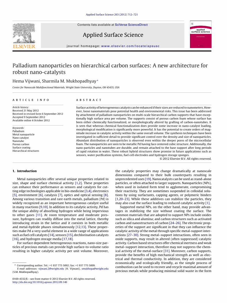
Fig. 1. SEM image of microstructure of carbon foam
.3. Synthesis of palladium nanoparticles
All the supports were rinsed with methanol and water prior toalladium deposition. In this study, supported Pd-NPs were fab-icated by the liquid-phase synthesis technique combined withhermal reduction process. TAPN of optimized concentration wassed as the metal precursor solution. The supports were immersedsoaked) in aqueous precursor solution, and then dried in a fur-ace followed by calcination at elevated temperatures. Heatingates needed to be carefully controlled in order to avoid sinter-ng. Calcination step was done in oxygen rich atmosphere (air) foroam samples, and oxygen deficient inert atmosphere (Ar) for CNT-ttached hierarchical samples. The samples were subsequentlyeduced at higher temperature with hydrogen gas in an inert atmo-phere (reduction step). The furnace was finally allowed to cool tooom temperature in the flowing mixture of Ar and H2. For addi-ional metal loading, the soaking, drying and calcining steps can beepeated multiple times (multiple coating cycles) prior to reductionntil desired amount of Pd is obtained.
X-ray photoelectron spectroscopy (XPS) was performedsing Kratos (Axis Ultra) system with mono-chromatizedl K� (1486.6 eV) source in ultra-high vacuum environment
UHV ∼ 10−9 Torr). The survey scans (BE: 1000–0 eV) were taken inhe retarding sweep modes and similarly high resolution fine scansf respective elements were also collected. The static charge (ifny) in the samples was corrected by assigning a value of 284.4 eVo C 1s spectrum, a well-known binding energy value of carbonn graphite [48]. Energy Dispersive Spectroscopy (EDAX) usingmetek Inc. EDAX system was also performed on these samples
or elemental data analysis.
.6. Crystal structure analysis
X-ray diffraction (XRD) patterns were obtained by X-ray mini-iffractometer, MD-10, using a monochromotized Cu K� radiation� = 1.5418 A) at 25 kV and 0.4 mA. XRD data was collected in the
and carbon nanotubes grafted on carbon foam (b).
range of 20◦ < 2� < 90◦ diffraction angle. The interplanar distance,dL was calculated from first order Bragg’s reflection.
2.7. Durability testing
The durability of Pd-NPs fabricated on carbon foam and CNT-grafted carbon foam was tested by subjecting it to prolongedrotations in water. The samples were taped to the walls of sealedserum bottle filled with water (∼60%). These bottles were rotatedat 32 revolutions per minute (rpm) continuously for 24–48 h percycle for 3–5 cycles. The samples were analyzed before and afterthese tests for microstructural and spectroscopic elemental datausing SEM and EDAX respectively.
3. Results and discussions
SEM micrographs of the carbon support are shown in Fig. 1.Fig. 1(a) is the original foam and Fig. 1(b) shows the higher magni-fication surface morphology of the walls if CNT are attached on thefoam.
3.1. Structural characterization of nanoparticles
The density (numbers per unit area) of metal NPs obtained onthe support depends on the interaction of the support with themetal-precursor solution as well as on the surface morphology ofthe support. The size, density, and dispersion of NPs can also befine-tuned by optimizing various process parameters. The majorvariables identified in this case were the concentration of TAPNsolution, the composition and temperature of the reducing environ-ment, as well as the number of coating cycles (each cycle includessoaking, drying and calcination) prior to reduction. It was observedthat higher concentrations of TAPN solution led to micron sizedparticles and the particle size decreased with reduction in con-centrations of the TAPN solution. The goal of this study was toidentify the influence of surface pretreatment on Pd nanoparticledistribution, therefore concentration and soaking times was opti-mized initially, and then maintained constant for all subsequentstudies. The influence of number of coating cycles was observed todepend upon the substrate morphology, as seen by the comparisonof one-coating cycle and two-coating cycle results shown below.
3.1.1. Influence of functional coatings
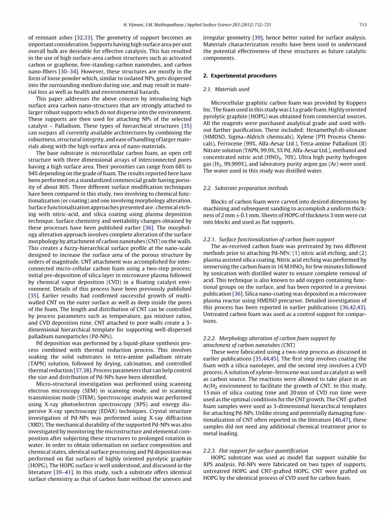
Fig. 2 shows the SEM micrographs of Pd-NPs deposited on the
untreated (a), nitric-acid treated (b), and silica coated (c) carbonfoam supports by a one-coating cycle process. The SEM micro-graphs reveal that both the pretreatment methods show noticeable
ig. 2. SEM micrographs showing (first pore) the samples with ONE-coating cyclearbon foam supports.
mprovement in the amount of Pd-NPs loading in comparison withhe untreated support.
Nitric-acid etching is a pretreatment method for oxidizing thearbon supports [36]. This approach etches the surface and resultsn the attachment of oxygen functional groups desirable for theucleation of the metal NPs. After treating with the HNO3, the foamupport was rinsed thoroughly with distilled water in order to stopdditional oxidization [36], and also to avoid the effects of vary-ng pH of the metal-precursor solution while soaking the support49]. The SEM micrograph of Pd-NPs fabricated on HNO3 treatedoam shows some improvement in the density of NPs as shown inig. 2b.
Pd-NPs on silica-coated porous foam were obtained as shownn Fig. 2(c). Among all the surface functionalized foam supports,ilica-coated foam appeared to be the most effective for deposit-ng Pd-NPs. The silica-coated sample consists of a nano-layer ofxide on the surface which enables the porous hydrophobic foamo become permanently hydrophilic. It improves the wetting abilityf the support as well as its interaction with the metal-precursorolution and therefore has better particle deposition.
Since Pd-NPs were successfully deposited throughout the poresf the foam samples, it can be inferred that the precursor solutionas effectively infiltrated into the porous support. However, someariation in the density of Pd-NPs was observed at different levelsf foam, from the top-ligament to the inner pores. There were alsoome “abnormal” regions showing different particle sizes and/orensities compared to the rest of the surface. Such variations wereignificantly reduced by the two coating-cycle process as shownelow.
.1.2. Influence of number of coating cyclesIn an effort to increase the amount of Pd loading and uniformity
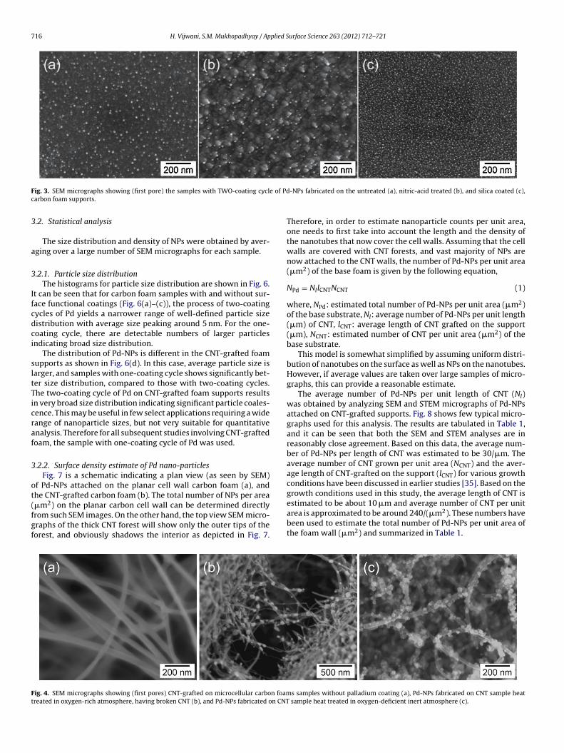
n nanoparticle distribution, an additional method of two-coatingycles was investigated. This implied repeating the cycles of soak-ng, drying, and calcination steps twice, prior to a reduction step.he SEM micrographs, as shown in Fig. 3, reveals that the two-oating cycles of Pd significantly enhances the amount of NPsoaded on the support. More importantly, uniform and well-ispersed, smaller Pd-NPs were obtained with the two-coated cyclef Pd in comparison to their single coated (one-coating cycle)ounterparts. It was also noticed that the areas with disparity inanoparticle loadings were significantly reduced with the two-oating cycle process.
It was again noticed that after the two-coating cycle deposi-
ion, Pd loading was maximum on silica treated foam, followed byNO3 treated, and least on untreated foam samples. It can be con-luded from this part of the study that the surface pretreatmentf foam increases density of Pd-NPs on the foam surface. This is
-NPs fabricated on the untreated (a), nitric-acid treated (b), and silica coated (c),
probably related to increased surface activity of the substrate thatresults in enhanced wettability with the precursor solution and alsofacilitates active sites for Pd nucleation.
3.1.3. Influence of nanotube-graftingThe SEM micrographs as shown in Figs. 1(b) and 4(a) shows
that CNT-grafted on carbon foam by the CVD process results inforest-like nanotubes. Pd-NPs were fabricated on such supportsby a similar process discussed earlier but with one difference, thecalcination step was performed in inert environment of Ar. Thiswas done because, the CNT thermally decompose when calcined inair or oxygen-rich environment at elevated temperatures (above400 ◦C) as shown in Fig. 4(b). However, when the samples werecalcined in an inert atmosphere of Ar no decomposition of CNTwas observed as shown in Fig. 4(C). Fig. 5 shows the SEM micro-graphs of Pd-NPs on CNT-grafted foam samples synthesized by theone-coating cycle (a), and two-coating cycles (b) of Pd depositionprocess. The remarkable increase in the number of NPs per areaof the CNT-grafted sample is clearly evident. It was also observedthat, unlike what was seen in bare foams, the particles size becamelarger and more uneven with two-coating cycles of Pd in this case.This may be attributed to the overlapping and intertwining of CNTthat increases the chances of more precursor clogging and particlecoalescence during the second coat.
Irrespective of the number of coating cycles, Pd-NPs on CNT-grafted supports were larger in size compared to that on the carbonfoam supports. Such a difference can be attributed to the (i) higherretention of precursor solution in the CNT forests and/or (ii) thecalcining environment. It is reported in the literature that at agiven temperature, the oxygen-deficit environment enhances themobility of particles [49–51]. The CNT-samples are calcined in inertatmosphere where the absence of oxygen may provide more scopefor particle mobility and coalescence in the given time.
It is worth noting that earlier studies in the literature relatedto CNT supported metal NPs involved loose CNT suspended in airor solution. Moreover, earlier studies often reported the need foreither electric field-dependant techniques, or “surface function-alization” treatments in order to attach NPs on nanotubes. Manysurface functionalization approaches are harsh enough to alter theCNT chemistry and/or damage its structural integrity [46,47]. Inthis study, metal NPs have been attached to nanotubes anchoredon large porous solids. Moreover, this has been achieved withoutany additional functionalization of the CNT. It is possible that the
dense CNT forest grown by the CVD technique in this study providessufficient surface-active defects as well as significant precursorretention during formation, which enables improved nucleation ofNPs without the need of damaging surface etch.
ig. 3. SEM micrographs showing (first pore) the samples with TWO-coating cyclarbon foam supports.
.2. Statistical analysis
The size distribution and density of NPs were obtained by aver-ging over a large number of SEM micrographs for each sample.
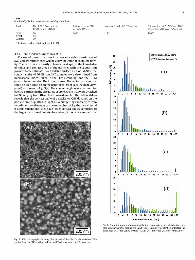
.2.1. Particle size distributionThe histograms for particle size distribution are shown in Fig. 6.
t can be seen that for carbon foam samples with and without sur-ace functional coatings (Fig. 6(a)–(c)), the process of two-coatingycles of Pd yields a narrower range of well-defined particle sizeistribution with average size peaking around 5 nm. For the one-oating cycle, there are detectable numbers of larger particlesndicating broad size distribution.
The distribution of Pd-NPs is different in the CNT-grafted foamupports as shown in Fig. 6(d). In this case, average particle size isarger, and samples with one-coating cycle shows significantly bet-er size distribution, compared to those with two-coating cycles.he two-coating cycle of Pd on CNT-grafted foam supports resultsn very broad size distribution indicating significant particle coales-ence. This may be useful in few select applications requiring a wideange of nanoparticle sizes, but not very suitable for quantitativenalysis. Therefore for all subsequent studies involving CNT-graftedoam, the sample with one-coating cycle of Pd was used.
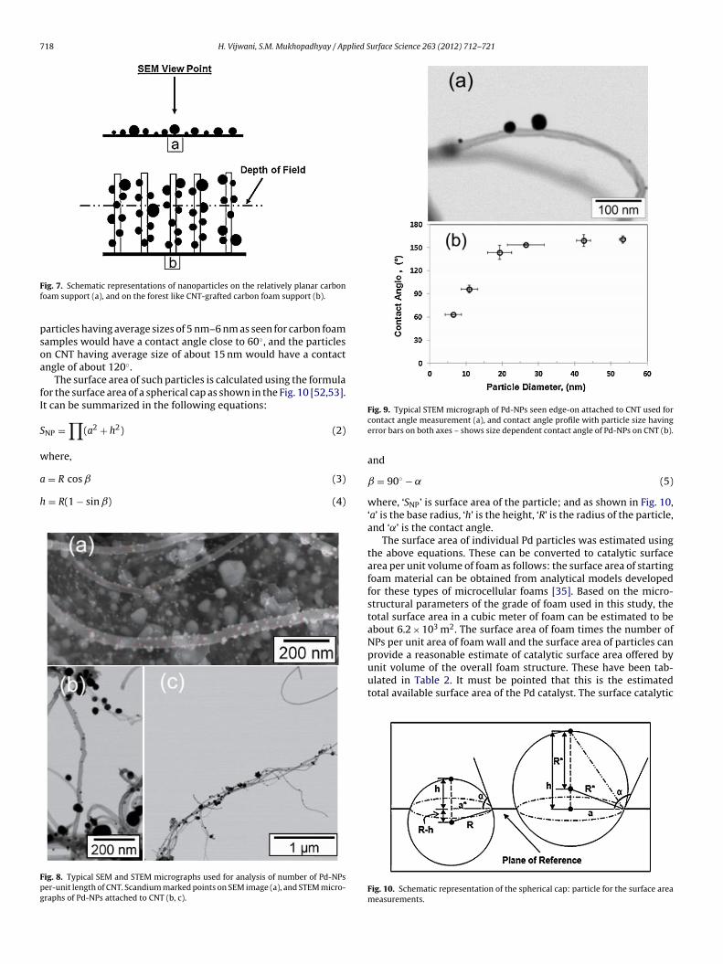
.2.2. Surface density estimate of Pd nano-particlesFig. 7 is a schematic indicating a plan view (as seen by SEM)
f Pd-NPs attached on the planar cell wall carbon foam (a), andhe CNT-grafted carbon foam (b). The total number of NPs per area
�m2) on the planar carbon cell wall can be determined directlyrom such SEM images. On the other hand, the top view SEM micro-raphs of the thick CNT forest will show only the outer tips of theorest, and obviously shadows the interior as depicted in Fig. 7.
ig. 4. SEM micrographs showing (first pores) CNT-grafted on microcellular carbon foamreated in oxygen-rich atmosphere, having broken CNT (b), and Pd-NPs fabricated on CNT
-NPs fabricated on the untreated (a), nitric-acid treated (b), and silica coated (c),
Therefore, in order to estimate nanoparticle counts per unit area,one needs to first take into account the length and the density ofthe nanotubes that now cover the cell walls. Assuming that the cellwalls are covered with CNT forests, and vast majority of NPs arenow attached to the CNT walls, the number of Pd-NPs per unit area(�m2) of the base foam is given by the following equation,
NPd = NllCNTNCNT (1)
where, NPd: estimated total number of Pd-NPs per unit area (�m2)of the base substrate, Nl: average number of Pd-NPs per unit length(�m) of CNT, lCNT: average length of CNT grafted on the support(�m), NCNT: estimated number of CNT per unit area (�m2) of thebase substrate.
This model is somewhat simplified by assuming uniform distri-bution of nanotubes on the surface as well as NPs on the nanotubes.However, if average values are taken over large samples of micro-graphs, this can provide a reasonable estimate.
The average number of Pd-NPs per unit length of CNT (Nl)was obtained by analyzing SEM and STEM micrographs of Pd-NPsattached on CNT-grafted supports. Fig. 8 shows few typical micro-graphs used for this analysis. The results are tabulated in Table 1,and it can be seen that both the SEM and STEM analyses are inreasonably close agreement. Based on this data, the average num-ber of Pd-NPs per length of CNT was estimated to be 30/�m. Theaverage number of CNT grown per unit area (NCNT) and the aver-age length of CNT-grafted on the support (lCNT) for various growthconditions have been discussed in earlier studies [35]. Based on thegrowth conditions used in this study, the average length of CNT is
estimated to be about 10 �m and average number of CNT per unitarea is approximated to be around 240/(�m2). These numbers havebeen used to estimate the total number of Pd-NPs per unit area ofthe foam wall (�m2) and summarized in Table 1.
s samples without palladium coating (a), Pd-NPs fabricated on CNT sample heatsample heat treated in oxygen-deficient inert atmosphere (c).
Table 1Density of palladium nanoparticles in CNT-grafted foam.
Mode No. of Pd-NPs per micronlength (�m)of CNT (Nl)
Estimated no. of CNTper �m2 (NCNT)
Average length of CNT (�m) (lCNT) Estimated no. of Pd-NPs/�m2 100%coverage of CNT (NPd = NlNCNTlCNT)
SEM 28 240a 10a 72000STEM 33Average 30
3
aiopcm(cpotrptit
Fg
a Estimated values obtained from Ref. [35].
.2.3. Total available surface area of PdFor use of these structures in advanced catalysis, estimates of
vailable Pd surface area will be a key indicator of chemical activ-ty. The particles are mostly spherical in shape, so the knowledgef radius and contact angle of the particles with the support canrovide some estimates for available surface area of Pd-NPs. Theontact angles of Pd-NPs on CNT samples were determined fromicroscopic images taken in the SEM (scanning) and the STEM
transmission) modes. The images were collected for particles thatould be seen edge-on on the nanotubes (from SEM incident view-oint) as shown in Fig. 9(a). The contact angle was measured forver 30 particles in the size range of up to 50 nm that were attachedo CNT ranging from 10 nm to 25 nm in diameter. The obtained dataeveals that the contact angle of particles on CNT depends on thearticle-size, as plotted in Fig. 9(b). While getting exact angles from
wo-dimensional images can be somewhat tricky, the overall trends clear: smaller particles have lower contact angles compared tohe larger ones. Based on this observation, it has been assumed that
ig. 5. SEM micrographs showing (first pores) of the Pd-NPs fabricated on CNT-rafted foam by ONE-coating cycle (a), and TWO-coating cycle (b), processes.
Fig. 6. Graphical representations of palladium nanoparticles size distribution pro-files. Comparing ONE-coating cycle and TWO-coating cycles of Pd on untreated (a),nitric-acid treated (b), silica treated (c), and CNT-grafted (d), carbon foam samples.
ig. 7. Schematic representations of nanoparticles on the relatively planar carbonoam support (a), and on the forest like CNT-grafted carbon foam support (b).
articles having average sizes of 5 nm–6 nm as seen for carbon foamamples would have a contact angle close to 60◦, and the particlesn CNT having average size of about 15 nm would have a contactngle of about 120◦.
The surface area of such particles is calculated using the formulaor the surface area of a spherical cap as shown in the Fig. 10 [52,53].t can be summarized in the following equations:
NP =∏
(a2 + h2) (2)
here,
= R cos ˇ (3)
= R(1 − sin ˇ) (4)
ig. 8. Typical SEM and STEM micrographs used for analysis of number of Pd-NPser-unit length of CNT. Scandium marked points on SEM image (a), and STEM micro-raphs of Pd-NPs attached to CNT (b, c).
Fig. 9. Typical STEM micrograph of Pd-NPs seen edge-on attached to CNT used forcontact angle measurement (a), and contact angle profile with particle size havingerror bars on both axes – shows size dependent contact angle of Pd-NPs on CNT (b).
and
ˇ = 90◦ − ˛ (5)
where, ‘SNP’ is surface area of the particle; and as shown in Fig. 10,‘a’ is the base radius, ‘h’ is the height, ‘R’ is the radius of the particle,and ‘˛’ is the contact angle.
The surface area of individual Pd particles was estimated usingthe above equations. These can be converted to catalytic surfacearea per unit volume of foam as follows: the surface area of startingfoam material can be obtained from analytical models developedfor these types of microcellular foams [35]. Based on the micro-structural parameters of the grade of foam used in this study, thetotal surface area in a cubic meter of foam can be estimated to beabout 6.2 × 10³ m2. The surface area of foam times the number ofNPs per unit area of foam wall and the surface area of particles can
provide a reasonable estimate of catalytic surface area offered byunit volume of the overall foam structure. These have been tab-ulated in Table 2. It must be pointed that this is the estimatedtotal available surface area of the Pd catalyst. The surface catalytic
Fig. 10. Schematic representation of the spherical cap: particle for the surface areameasurements.
after these tests. This observation clearly shows that, for the timeand intensity tested, these materials are robust and durable.
The successful fabrication and characterization of these mate-
Two 4.7 ± 3.24 CNT grafted One 15.1 ± 15
Two 30.3 ± 22
ctivity of nano-sized particles for specific reactions may have sizeependant effects that are not yet understood clearly [54,55]. In thebsence of such understanding, however, the total surface area ofd per unit area of substrate does provide a useful estimate of theotential effectiveness of these supported catalyst structures.
It is very clear from these results that advanced surface modifi-ation techniques such as oxide functionalization can provide about-fold increase in available Pd surface per unit area of substrate. Onhe other hand, the nanotube attachment approach can increasehis by over three orders of magnitude.
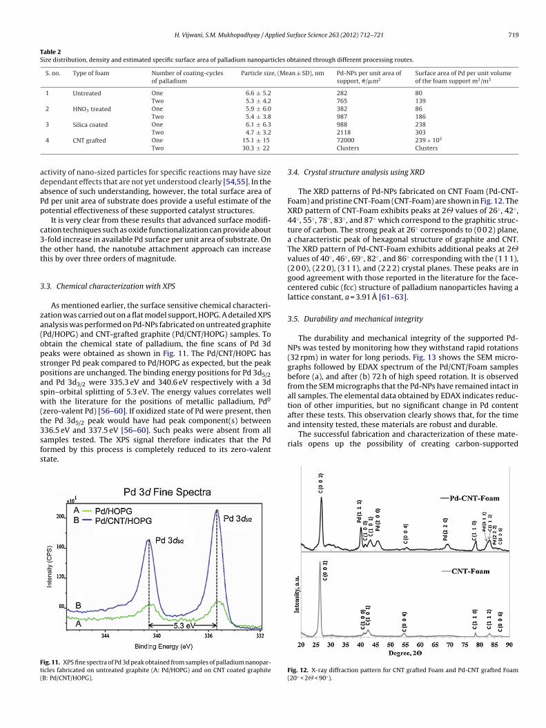
.3. Chemical characterization with XPS
As mentioned earlier, the surface sensitive chemical characteri-ation was carried out on a flat model support, HOPG. A detailed XPSnalysis was performed on Pd-NPs fabricated on untreated graphitePd/HOPG) and CNT-grafted graphite (Pd/CNT/HOPG) samples. Tobtain the chemical state of palladium, the fine scans of Pd 3deaks were obtained as shown in Fig. 11. The Pd/CNT/HOPG hastronger Pd peak compared to Pd/HOPG as expected, but the peakositions are unchanged. The binding energy positions for Pd 3d5/2nd Pd 3d3/2 were 335.3 eV and 340.6 eV respectively with a 3dpin–orbital splitting of 5.3 eV. The energy values correlates wellith the literature for the positions of metallic palladium, Pd0
zero-valent Pd) [56–60]. If oxidized state of Pd were present, thenhe Pd 3d5/2 peak would have had peak component(s) between36.5 eV and 337.5 eV [56–60]. Such peaks were absent from all
amples tested. The XPS signal therefore indicates that the Pdormed by this process is completely reduced to its zero-valenttate.
ig. 11. XPS fine spectra of Pd 3d peak obtained from samples of palladium nanopar-icles fabricated on untreated graphite (A: Pd/HOPG) and on CNT coated graphiteB: Pd/CNT/HOPG).
2118 30372000 239 × 103
Clusters Clusters
3.4. Crystal structure analysis using XRD
The XRD patterns of Pd-NPs fabricated on CNT Foam (Pd-CNT-Foam) and pristine CNT-Foam (CNT-Foam) are shown in Fig. 12. TheXRD pattern of CNT-Foam exhibits peaks at 2� values of 26◦, 42◦,44◦, 55◦, 78◦, 83◦, and 87◦ which correspond to the graphitic struc-ture of carbon. The strong peak at 26◦ corresponds to (0 0 2) plane,a characteristic peak of hexagonal structure of graphite and CNT.The XRD pattern of Pd-CNT-Foam exhibits additional peaks at 2�values of 40◦, 46◦, 69◦, 82◦, and 86◦ corresponding with the (1 1 1),(2 0 0), (2 2 0), (3 1 1), and (2 2 2) crystal planes. These peaks are ingood agreement with those reported in the literature for the face-centered cubic (fcc) structure of palladium nanoparticles having alattice constant, a = 3.91 A [61–63].
3.5. Durability and mechanical integrity
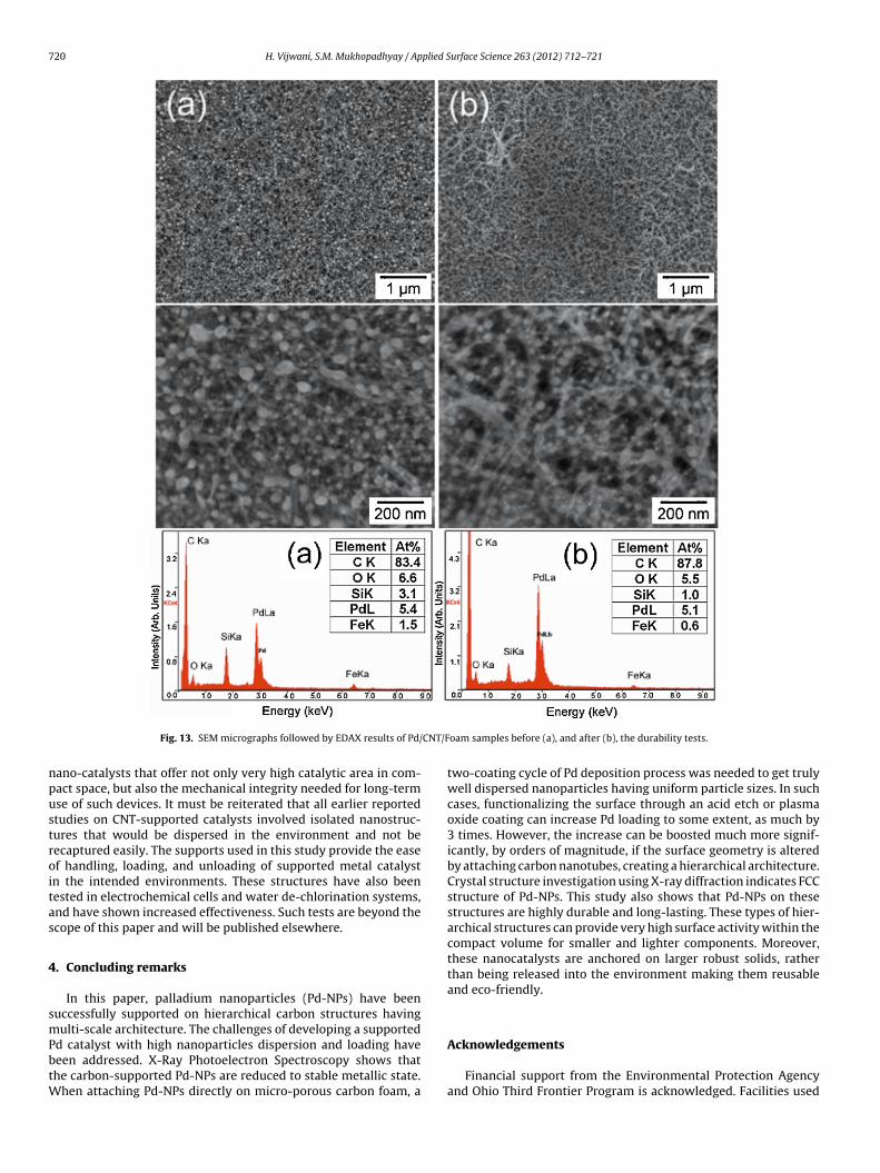
The durability and mechanical integrity of the supported Pd-NPs was tested by monitoring how they withstand rapid rotations(32 rpm) in water for long periods. Fig. 13 shows the SEM micro-graphs followed by EDAX spectrum of the Pd/CNT/Foam samplesbefore (a), and after (b) 72 h of high speed rotation. It is observedfrom the SEM micrographs that the Pd-NPs have remained intact inall samples. The elemental data obtained by EDAX indicates reduc-tion of other impurities, but no significant change in Pd content
rials opens up the possibility of creating carbon-supported
Fig. 12. X-ray diffraction pattern for CNT grafted Foam and Pd-CNT grafted Foam(20◦ < 2� < 90◦).
Fig. 13. SEM micrographs followed by EDAX results of Pd/
ano-catalysts that offer not only very high catalytic area in com-act space, but also the mechanical integrity needed for long-termse of such devices. It must be reiterated that all earlier reportedtudies on CNT-supported catalysts involved isolated nanostruc-ures that would be dispersed in the environment and not beecaptured easily. The supports used in this study provide the easef handling, loading, and unloading of supported metal catalystn the intended environments. These structures have also beenested in electrochemical cells and water de-chlorination systems,nd have shown increased effectiveness. Such tests are beyond thecope of this paper and will be published elsewhere.
. Concluding remarks
In this paper, palladium nanoparticles (Pd-NPs) have beenuccessfully supported on hierarchical carbon structures havingulti-scale architecture. The challenges of developing a supported
d catalyst with high nanoparticles dispersion and loading haveeen addressed. X-Ray Photoelectron Spectroscopy shows thathe carbon-supported Pd-NPs are reduced to stable metallic state.
hen attaching Pd-NPs directly on micro-porous carbon foam, a
oam samples before (a), and after (b), the durability tests.
two-coating cycle of Pd deposition process was needed to get trulywell dispersed nanoparticles having uniform particle sizes. In suchcases, functionalizing the surface through an acid etch or plasmaoxide coating can increase Pd loading to some extent, as much by3 times. However, the increase can be boosted much more signif-icantly, by orders of magnitude, if the surface geometry is alteredby attaching carbon nanotubes, creating a hierarchical architecture.Crystal structure investigation using X-ray diffraction indicates FCCstructure of Pd-NPs. This study also shows that Pd-NPs on thesestructures are highly durable and long-lasting. These types of hier-archical structures can provide very high surface activity within thecompact volume for smaller and lighter components. Moreover,these nanocatalysts are anchored on larger robust solids, ratherthan being released into the environment making them reusableand eco-friendly.
Acknowledgements
Financial support from the Environmental Protection Agencyand Ohio Third Frontier Program is acknowledged. Facilities used
plied S
wt
R
[[
[[[
[
[
[[[[
[
[[
[[
[[[
[[[
[
[
[
[
[
[
[
[
[[
[
[
[
[
[
[
[[
[
[
[
[
[
[
[
[
[
[
H. Vijwani, S.M. Mukhopadhyay / Ap
ere funded by NSF-MRI award and Ohio Board of Regents. Wehank Koppers Inc. for generous supply of carbon foams.
eferences
[1] G. Schmid, Chemical Reviews 92 (1992) 1709–1727.[2] L.J. de Jongh, Applied Organometallic Chemistry 12 (1998) 393–399.[3] S. Guo, S. Dong, Trends in Analytical Chemistry 28 (2009) 96–109.[4] M. Gao, H. Qi, Q. Gao, C. Zhang, Electroanalysis 20 (2008) 123–130.[5] S.H. Ko, I. Park, H. Pan, C.P. Grigoropoulos, A.P. Pisano, C.K. Luscombe, J.M.J
Frechet, Nano Letters 7 (2007) 1869–1877.[6] W. Zhang, Journal of Nanoparticle Research 5 (2003) 323–332.[7] C. Wang, M. Waje, X. Wang, J.M. Tang, R.C. Haddon, Y. Yan, Nano Letters 4 (2004)
345–348.[8] D. Monzon-Hernandeza, D. Luna-Morenoa, D.M. Escobara, J. Villatoro, Sensors
& Actuators B: Chemical 151 (2010) 219–222.[9] Y. Li, X. Fan, J. Qi, J. Ji, S. Wang, G. Zhang, F. Zhang, Nano Research 3 (2010)
429–437.10] L. Yin, J. Liebscher, Chemical Reviews 107 (2007) 133–173.11] C. Batchelor-McAuley, C.E. Banks, A.O. Simm, T.G.J. Jones, R.G. Compton,
ChemPhysChem 7 (2006) 1081–1085.12] L. Schlapbach, A. Zuttel, Nature 414 (2001) 353–358.13] W. Grochala, P.P. Edwards, Chemical Reviews 104 (2004) 1283–1315.14] S. Grigoriev, E. Lyutikova, S. Martemianov, V. Fateev, C. Lebouin, P. Millet, WHEC
16 (2006) 13–16.15] Z. Chang, H. Fan, K. Zhao, M. Chen, P. He, Y. Fang, Electroanalysis 20 (2008)
3217–3223.17] Z. Shi, J.A. Szpunar, Reviews on Advanced Materials Science 15 (2007) 1–9.18] F. Rahimi, A.I. Zad, Journal of Physics D: Applied Physics 40 (2007) 7201–7209.19] G.C. Bond, Surface Science 156 (1985) 966–981.20] J. Turkevich, P.C. Stevenson, J. Hillier, Discussions of the Faraday Society 11
(1951) 55–75.21] R.M. Crooks, M.Q. Zhao, L. Sun, V. Chechik, L.K. Yeung, Accounts of Chemical
Research 34 (2001) 181–190.22] S.U. Son, Y. Jang, K.Y. Yoon, E. Kang, T. Hyeon, Nano Letters 4 (2004) 1147–1151.23] M.A.R. Meier, M. Filali, J.F. Gohy, U.S. Schubert, Journal of Materials Chemistry
16 (2006) 3001–3006.24] M. Platt, R.A.W. Dryfe, E.P.L. Roberts, Electrochimica Acta 48 (2003) 3037–3046.25] I. Yuranov, P. Moeckli, E. Suvorova, P. Buffat, L. Kiwi-Minsker, A. Renken, Journal
of Molecular Catalysis A: Chemical 192 (2003) 239–251.26] G.C. Wildgoose, C.E. Banks, R.G. Compton, Small 2 (2006) 182–193.27] G.C. Bond, Platinum Metals Reviews 27 (1983) 16–18.28] S.J. Tauster, S.C. Fung, R.L. Garten, Journal of the American Chemical Society 100
(1978) 170–175.29] S.J. Tauster, S.C. Fung, R.T.K. Baker, J.A. Horsley, Science 211 (1981) 1121–1125.30] S.J. Tauster, Accounts of Chemical Research 20 (1987) 389–394.31] D.J. Suh, C. Kwak, J.H. Kim, S.M. Kwon, T.J. Park, Journal of Power Sources 142
(2005) 70–74.
32] E. Auer, A. Freund, J. Pietsch, T. Tacke, Applied Catalysis A 173 (1998)
259–271.33] A. Cabiac, T. Cacciaguerra, P. Trens, R. Durand, G. Delhay, A. Medevielle, D. Plee,
B. Coq, Applied Catalysis A 340 (2008) 229–235.34] C.L. Lee, Y.C. Huang, L.C. Kuo, Y.W. Lin, Carbon 45 (2007) 203–228.
[[[
[
urface Science 263 (2012) 712–721 721
35] S.M. Mukhopadhyay, A. Karumuri, I. Barney, Journal of Physics D: AppliedPhysics 42 (2009) 195503–195512.
37] W.C. Mosley, 1993, Palladium/Kieselguhr composition and method UnitedStates Patent, US Patent 5248649.
38] A.F. Perez-Cadenas, S. Morales-Torres, F. Kapteijn, F.J. Maldonado-Hodar, F.Carrasco-Marin, C. Moreno-Castilla, J.A. Moulijn, Applied Catalysis B 77 (2008)272–277.
39] S.M. Mukhopadhyay, N. Mahadev, P. Joshi, A.K. Roy, K.M. Kearns, D.P. Anderson,Journal of Applied Physics 91 (2002) 3415–3420.
40] E. Sacher, Langmuir 26 (2010) 3807–3814.41] S. Niyogi, M.A. Hamon, H. Hu, B. Zhao, P. Bhowmik, R. Sen, M.E. Itkis, R.C. Haddon,
Accounts of Chemical Research 35 (2002) 1105–1113.42] S.M. Mukhopadhyay, P. Joshi, R.V. Pulikollu, Tsinghua Science and Technology
10 (2005) 709–717.43] S.M. Mukhopadhyay, P. Joshi, S. Datta, J. Macdaniel, Applied Surface Science
59] I. Kojima, M. Kurahashi, Journal of Electron Spectroscopy and RelatedPhenomena 42 (1987) 177–181.
60] H. Wang, Y. Wan, Journal of Materials Science 44 (2009) 6553–6562.61] A.K. Mishra, S. Ramaprabhu, Chemical Engineering Journal 187 (2012) 10–15.62] Y.-H. Qin, Y.-B. Jia, Y. Jiang, D.-F. Niu, X.-S. Zhang, X.-G. Zhou, L. Niu, W-K. Yuan,
International Journal of Hydrogen Energy 37 (2012) 7373–7377.63] T. Teranishi, M. Miyake, Chemistry of Materials 10 (1998) 594–600.


![Aerosol-Based Self-Assembly of Nanoparticles into Solid or …npt.pusan.ac.kr/sites/npt/download/[29]Langmuir2010.pdf · 2018-01-12 · 4 nanoparticles, into hierarchical composite](https://static.documents.pub/doc/80x56/5f49a97df7e8d1699d355d6b/aerosol-based-self-assembly-of-nanoparticles-into-solid-or-nptpusanackrsitesnptdownload29.jpg)


