Page 1
Palo Alto Networks PA-200, PA-500, PA-2000 Series,
PA-3000 Series, PA-4000 Series, PA-5000 Series, PA-
7000 Series, VM Series, Next-Generation Firewall with
PAN-OS v7.0.8 and v7.1.3
Security Target
Version 1.2
2 November 2016
Prepared for:
Palo Alto Networks, Inc.
4401 Great America Parkway
Santa Clara, CA 95054
Prepared by:
Accredited Testing and Evaluation Labs
6841 Benjamin Franklin Drive
Columbia, MD 21046
Page 2
Security Target Version 1.2, 11/02/2016
Page ii of iii
Table of Contents 1. SECURITY TARGET INTRODUCTION ........................................................................................................... 1
1.1 SECURITY TARGET, TOE AND CC IDENTIFICATION ........................................................................................ 1 1.2 CONFORMANCE CLAIMS ................................................................................................................................. 2 1.3 CONVENTIONS ................................................................................................................................................ 3
1.3.1 Terminology .......................................................................................................................................... 3
1.3.2 Acronyms ............................................................................................................................................... 3
2. TOE DESCRIPTION .......................................................................................................................................... 5
2.1 TOE OVERVIEW ........................................................................................................................................... 5
2.2 TOE ARCHITECTURE ...................................................................................................................................... 7 2.2.1 Physical Boundaries ............................................................................................................................. 10
2.2.2 Logical Boundaries .............................................................................................................................. 17
2.3 TOE DOCUMENTATION ................................................................................................................................ 19
3. SECURITY PROBLEM DEFINITION .......................................................................................................... 20
4. SECURITY OBJECTIVES .............................................................................................................................. 21
4.1 SECURITY OBJECTIVES FOR THE OPERATIONAL ENVIRONMENT ................................................................... 21
5. IT SECURITY REQUIREMENTS .................................................................................................................. 22
5.1 EXTENDED REQUIREMENTS .......................................................................................................................... 22 5.2 TOE SECURITY FUNCTIONAL REQUIREMENTS ............................................................................................. 23
5.2.1 Security Audit (FAU) .......................................................................................................................... 24
5.2.2 Cryptographic Support (FCS) .............................................................................................................. 26
5.2.3 User Data Protection (FDP) ................................................................................................................. 29
5.2.4 Identification and Authentication (FIA) .............................................................................................. 29
5.2.5 Stateful Traffic Filtering (FFW) .......................................................................................................... 30
5.2.6 Security Management (FMT) .............................................................................................................. 32
5.2.7 Packet Filtering (FPF) .......................................................................................................................... 33
5.2.8 Protection of the TSF (FPT) ................................................................................................................ 34
5.2.9 TOE Access (FTA) .............................................................................................................................. 34
5.2.10 Trusted Path/Channels (FTP) ............................................................................................................... 35
5.3 TOE SECURITY ASSURANCE REQUIREMENTS ............................................................................................... 36
6. TOE SUMMARY SPECIFICATION .............................................................................................................. 37
6.1 SECURITY AUDIT .......................................................................................................................................... 37 6.2 CRYPTOGRAPHIC SUPPORT ........................................................................................................................... 38 6.3 USER DATA PROTECTION ............................................................................................................................. 43 6.4 IDENTIFICATION AND AUTHENTICATION ...................................................................................................... 43 6.5 SECURITY MANAGEMENT ............................................................................................................................. 45 6.6 PROTECTION OF THE TSF ............................................................................................................................. 46 6.7 TOE ACCESS ................................................................................................................................................ 48 6.8 TRUSTED PATH/CHANNELS ........................................................................................................................... 49 6.9 PACKET FILTERING ....................................................................................................................................... 49 6.10 STATEFUL TRAFFIC FILTERING ..................................................................................................................... 50
7. PROTECTION PROFILE CLAIMS ............................................................................................................... 55
Page 3
Security Target Version 1.2, 11/02/2016
Page iii of iii
8. RATIONALE ..................................................................................................................................................... 57
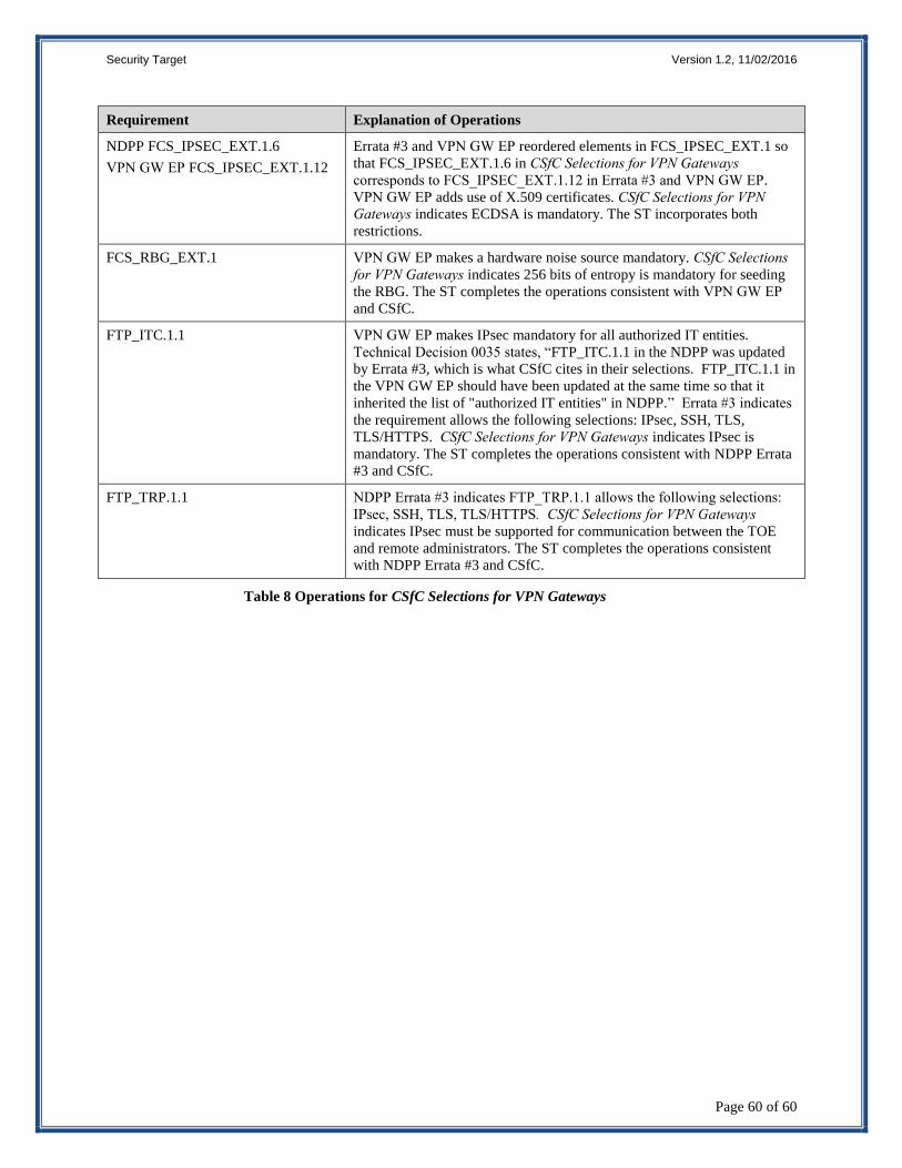
8.1 TOE SUMMARY SPECIFICATION RATIONALE ................................................................................................ 57 8.2 CSFC SELECTIONS FOR VPN GATEWAYS ..................................................................................................... 59
LIST OF TABLES
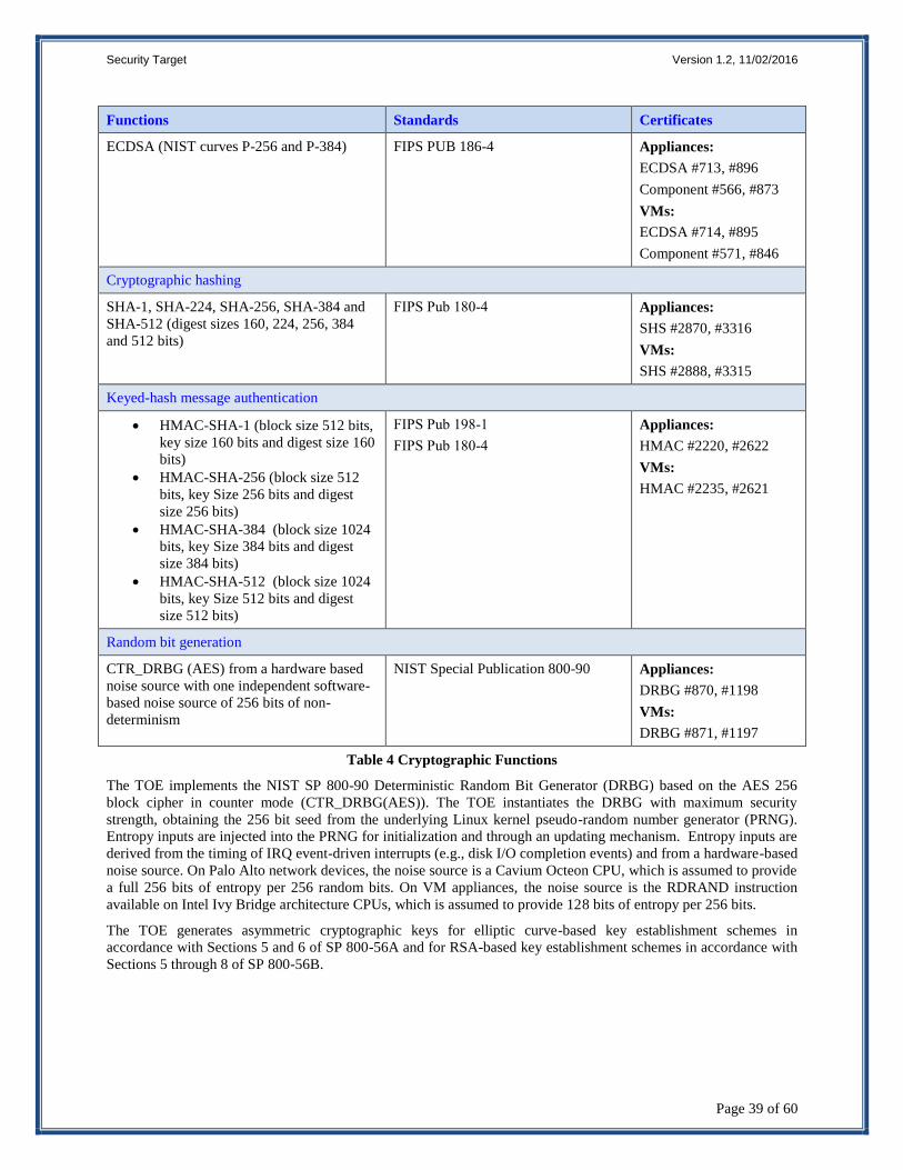
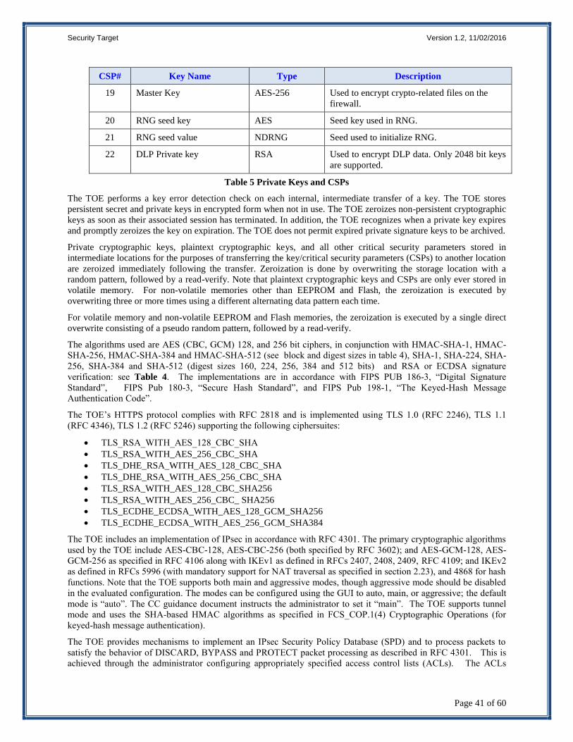
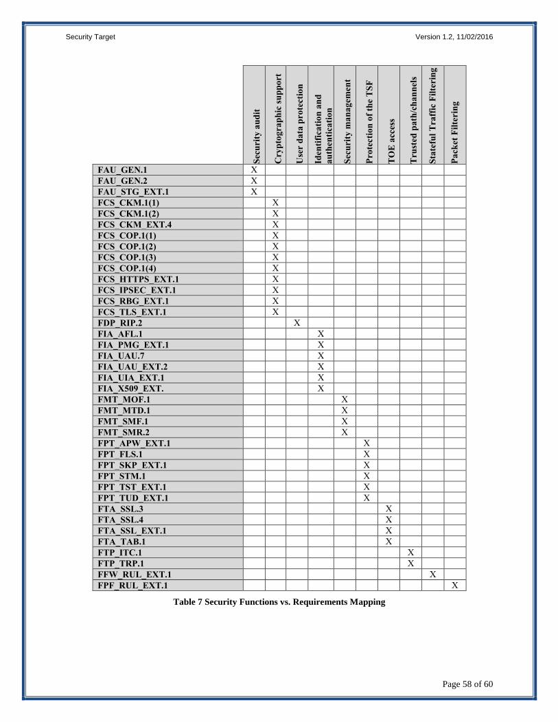
Table 1 TOE Security Functional Components ...................................................................................................... 24 Table 2 Auditable Events .......................................................................................................................................... 26 Table 3 Assurance Components ............................................................................................................................... 36 Table 4 Cryptographic Functions ............................................................................................................................ 39 Table 5 Private Keys and CSPs ................................................................................................................................ 41 Table 6 SFR Protection Profile Sources .................................................................................................................. 56 Table 7 Security Functions vs. Requirements Mapping ......................................................................................... 58 Table 8 Operations for CSfC Selections for VPN Gateways.................................................................................... 60
Page 4
Security Target Version 1.2, 11/02/2016
Page 1 of 60
1. Security Target Introduction
This section identifies the Security Target (ST) and Target of Evaluation (TOE) identification, ST conventions, ST
conformance claims, and the ST organization. The TOE is the next-generation firewall running PAN-OS v7.0.8 or
PAN-OS v7.1.3, with the User Identification Agent 7.0 provided by Palo Alto Networks Inc.
The next-generation firewall includes the PA-200, PA-500, PA-2020, PA-2050, PA-3020, PA-3050, PA-3060, PA-
4020, PA-4050, PA-4060, PA-5020, PA-5050, PA-5060, PA-7050, and PA-7080 appliances and the virtual
appliances in the VM-Series VM-100, VM-200, VM-300, VM-1000-HV which are used to manage enterprise
network traffic flows using function specific processing for networking, security, and management. The next-
generation firewalls identify which applications are flowing across the network, irrespective of port, protocol, or
SSL encryption. The User Identification Agent 7.0 (installed on a PC in the network) communicates with the
domain controller to retrieve user-specific information. It allows the next-generation firewall to automatically collect
user information and include it in policies and reporting.
The focus of this evaluation is on the TOE functionality supporting the claims in the Protection Profile for Network
Devices with the inclusion of the Stateful Traffic Filter Firewall and the VPN Gateway Extended Packages (See
section 1.2 for specific version information). The only capabilities covered by the evaluation are those specified in
the aforementioned Protection Profiles, all other capabilities are not covered in the evaluation. The security
functionality specified in [NDPP], the [STFF], and the [VPNGW] includes protection of communications between
TOE components and trusted IT entities, identification and authentication of administrators, auditing of security-
relevant events, ability to verify the source and integrity of updates to the TOE, the implementation of firewall-
related security features, the termination of IPsec VPN tunnels, and specifies FIPS-validated cryptographic
mechanisms.
The Security Target contains the following additional sections:
TOE Description (Section 2)
Security Problem Definition (Section 3)
Security Objectives (Section 4)
IT Security Requirements (Section 5)
TOE Summary Specification (Section 6)
Protection Profile Claims (Section 7)
Rationale (Section 8).
1.1 Security Target, TOE and CC Identification
ST Title – Palo Alto Networks PA-200, PA-500, PA-2000 Series, PA-3000 Series, PA-4000 Series, PA-5000
Series, PA-7000 Series, VM Series, Next-Generation Firewall with PAN-OS v7.0.8 and v7.1.3 Security Target
ST Version – Version 1.2
ST Date – 2 November 2016
TOE Identification – Palo Alto Networks PA-200, PA-500, PA-2000 Series, PA-3000 Series, PA-4000 Series, PA-
5000 Series, PA-7000 Series, VM Series, Next-Generation Firewall with PAN-OS v7.0.8 or PAN-OS 7.1.3. The
specific Firewall appliance models include:
1. PA-200
2. PA-500
3. PA-2000
a. PA-2020
b. PA-2050
4. PA-3000
a. PA-3020
Page 5
Security Target Version 1.2, 11/02/2016
Page 2 of 60
b. PA-3050
c. PA-3060
5. PA-4000
a. PA-4020
b. PA-4050
c. PA-4060
6. PA-5000
a. PA-5020
b. PA-5050
c. PA-5060
7. PA-7000
a. PA-7050
b. PA-7080
8. VM-Series—the following virtual appliances when installed on a specified hardware platform (see below)
that includes VMware ESXi 5.5 hypervisor and an Intel Core or Xeon processor based on the Ivy Bridge or
Haswell microarchitectures, which implement Intel Secure Key:
a. VM-1000-HV b. VM-300 c. VM-200 d. VM-100
Note, the NDPP specifies requirements for a network device—a device composed of hardware and
software that is connected to the network and has an infrastructure role on the network. Therefore, the VM-
Series virtual appliances are considered to be in their evaluated configuration only when installed on the
following specified hardware platforms and are not evaluated for deployment on any other platforms.
Dell PowerEdge R430, R530, R630, R730, R730xd and R930 Servers Equivalent platforms i.e., Intel Ivy Bridge or Haswell-based processor with Broadcom or Intel
Network Interface Controllers supported by the server
In addition, the VM-Series virtual appliance must be the only guest running in the virtualized environment.
Evaluation testing included the VM-300 installed on a Dell PowerEdge R730 Server running VMware
ESXi 5.5 on an Intel Xeon E5-2630 v3 (Haswell microarchitecture) processor with Broadcom 5720 NIC.
TOE Developer – Palo Alto Networks, Inc.
Evaluation Sponsor – Palo Alto Networks, Inc.
CC Identification – Common Criteria for Information Technology Security Evaluation, Version 3.1, Revision 4,
September 2012
1.2 Conformance Claims
This TOE is conformant to the following CC specifications:
This ST is conformant to:
Protection Profile for Network Devices, Version 1.1, 8 June 2012 (NDPP) as amended by Errata
#3 dated 3 November 2014 and CSfC Selections for VPN Gateways,
Network Device Protection Profile (NDPP) Extended Package Stateful Traffic Filter Firewall,
Version 1.0, 19 December 2011 (STFF)
Network Device Protection Profile (NDPP) Extended Package VPN Gateway, Version 1.1, 12
April 2013 (VPNGW) as amended by CSfC Selections for VPN Gateways (CSfC).
Common Criteria for Information Technology Security Evaluation Part 2: Security functional components,
Version 3.1, Revision 4, September 2012.
Part 2 Extended
Page 6
Security Target Version 1.2, 11/02/2016
Page 3 of 60
Common Criteria for Information Technology Security Evaluation Part 3: Security assurance components,
Version 3.1 Revision 4, September 2012.
Part 3 Conformant.
1.3 Conventions
The following conventions have been applied in this document:
Security Functional Requirements – Part 2 of the CC defines the approved set of operations that may be
applied to functional requirements: iteration, assignment, selection, and refinement.
o Iteration: allows a component to be used more than once with varying operations. In the ST,
iteration is indicated by a number in parentheses placed at the end of the component. For example
FDP_ACC.1 (1) and FDP_ACC.1 (2) indicate that the ST includes two iterations of the
FDP_ACC.1 requirement, (1) and (2).
o Assignment: allows the specification of an identified parameter. Assignments are indicated using
bold and are surrounded by brackets (e.g., [assignment]). Note that an assignment within a
selection would be identified in italics and with embedded bold brackets (e.g., [[selected-
assignment]]).
o Selection: allows the specification of one or more elements from a list. Selections are indicated
using bold italics and are surrounded by brackets (e.g., [selection]).
o Refinement: allows the addition of details. Refinements are indicated using bold, for additions,
and strike-through, for deletions (e.g., “… all objects …” or “… some big things …”). Note that
‘cases’ that are not applicable in a given SFR have simply been removed without any explicit
identification.
The NDPP uses an additional convention – the ‘case’ – which defines parts of an SFR that apply only when
corresponding selections are made or some other identified conditions exist. Only the applicable cases are
identified in this ST and they are identified using bold text.
Other sections of the ST – Other sections of the ST use bolding to highlight text of special interest, such as
captions.
1.3.1 Terminology
The following terms and abbreviations are used in this ST:
Security policy Provides the firewall rule sets that specify whether to block or allow network connections.
Security profile A security profile specifies protection rules to apply when processing network traffic. The
profiles supported by the TOE include the IPSec crypto Security profile, and the IKE Network
profile.
Security zone A grouping of TOE interfaces. Each TOE interface must be assigned to a zone before it can
process traffic.
Virtual system Virtual systems are separate, logical firewall instances within a single physical Palo Alto
Networks firewall. Virtual systems allow the TOE administrator to customize administration,
networking, and security policies for network traffic belonging to specific user groupings (such
as departments or customers).
1.3.2 Acronyms
AES Advanced Encryption Standard
CBC Cipher-Block Chaining
CC Common Criteria for Information Technology Security Evaluation
CEM Common Evaluation Methodology for Information Technology Security
CM Configuration Management
Page 7
Security Target Version 1.2, 11/02/2016
Page 4 of 60
CLI Command Line Interface
CPU Central Processing Unit
DH Diffie-Hellman
EEPROM Electrically Erasable Programmable Read-Only Memory
EP Extended Package
FIA Identification and Authentication CC Class
FIPS Federal Information Processing Standard
FMT Security Management CC Class
FSP Functional Specification
FTP File Transfer Protocol
GUI Graphical User Interface
HMAC Hashed Message Authentication Code
HTTP(S) Hypertext Transfer Protocol (Secure)
IKE Internet Key Exchange
IPsec Internet Protocol Security
IP Internet Protocol
IPv4 Internet Protocol version 4
IPv6 Internet Protocol version 6
IPSEC Internet Protocol Security
NDPP Protection Profile for Network Devices
NAT Network Address Translation
NIST National Institute of Standards and Technology
PP Protection Profile
QoS Quality of Service
REST Representational State Transfer
RSA Rivest, Shamir and Adleman (algorithm for public-key cryptography)
SA Security Association
SAR Security Assurance Requirement
SFP Security Function Policy
SFR Security Functional Requirement
SHA Secure Hash Algorithm
SM Security Management
SMR Security Management Roles
SMTP Simple Mail Transfer Protocol
SNMP Simple Network Management Protocol
SSH Secure Shell
SSL Secure Socket Layer Protocol
ST Security Target
STFF Stateful Traffic Filter Firewall (EP)
TCP Transmission Control Protocol
TLS Transport Layer Security
TOE Target of Evaluation
TSF TOE Security Functions
TSP TOE Security Policy
UDP User Data Protection
URL Uniform Resource Locator
VLAN Virtual Local Area Network
VM Virtual Machine
VPN Virtual Private Network
VPNGW VPN Gateway (EP)
Page 8
Security Target Version 1.2, 11/02/2016
Page 5 of 60
2. TOE Description
The Target of Evaluation (TOE) is Palo Alto Networks next-generation firewall that includes the PA-200, PA-500,
PA-2020, PA-2050, PA-3020, PA-3050, PA-3060, PA-4020, PA-4050, PA-4060, PA-5020, PA-5050, PA-5060,
PA-7050, PA-7080 appliances and the virtual appliances in the VM-Series VM-100, VM-200, VM-300, VM-1000-
HV, with PAN-OS v7.0.8 or PAN-OS v7.1.3. The next-generation firewall provides policy-based application
visibility and control to protect traffic flowing through the enterprise network.
2.1 TOE Overview
The next-generation firewalls are network firewall appliances and virtual appliances on specified hardware used to
manage enterprise network traffic flow using function specific processing for networking, security, and
management. The next-generation firewalls let the administrator specify security policies based on an accurate
identification of each application seeking access to the protected network. The next-generation firewall uses packet
inspection and a library of applications to distinguish between applications that have the same protocol and port, and
to identify potentially malicious applications that use non-standard ports. The next-generation firewall also supports
the establishment of Virtual Private Network (VPN) connections to other next-generation firewalls or third party
security devices.
A next-generation firewall is typically installed between an edge router or other device facing the Internet and a
switch or router connecting to the internal network. The Ethernet interfaces on the firewall can be configured to
support various networking environments, including: Layer 2 switching and VLAN environments; Layer 3 routing
environments; transparent in-line deployments; and combinations of the three.
The next-generation firewalls provide granular control over the traffic allowed to access the protected network.
They allow an administrator to define security policies for specific applications, rather than rely on a single policy
for connections to a given port number. For each identified application, the administrator can specify a security
policy to block or allow traffic based on the source and destination zones, source and destination addresses, or
application services. The next-generation firewalls also support the following types of policy:
Secure Socket Layer (SSL) decryption policies
SSH Decryption is checked using the SSH application signature, a policy lookup will occur on the decrypt
rule to see if this session should be decrypted.
Application Override policies
User Identification Agent (UIA) policy enforcement - the UIA provides the firewall with the capability to
automatically collect user-specific information, and provides mapping information between IP addresses
and network users, that is used in security policy enforcement and reporting. The user id can be an attribute
specified in the TOE security policies upon which they are enforced. The UIA works only for IPv4
addresses.
Security policies can include specification of one or more security profiles, which provide additional protection and
control. Security profiles are configured and applied to firewall policy. Each security policy can specify one or
more of the following security profiles:
Antivirus profiles
Antispyware profiles
Vulnerability Protection profiles
File blocking profiles
URL filtering profiles
Data Filtering profiles
DoS Protection profiles
Page 9
Security Target Version 1.2, 11/02/2016
Page 6 of 60
IPSec crypto Security profiles
IKE Network profiles
The next-generation firewall products provide the following features:
Application-based policy enforcement — the product uses a traffic classification technology named App-
ID to classify traffic by application content irrespective of port or protocol. Protocol and port can be used
in conjunction with application identification to control what ports an application is allowed to run on.
High risk applications can be blocked, as well as high-risk behavior such as file-sharing. SSL encrypted
traffic can be decrypted and inspected.
Threat prevention — the firewall includes threat prevention capabilities that can protect the network from
viruses, worms, spyware, and other malicious traffic.
Traffic visibility — the firewall includes the capability to generate extensive reports, logs, and notification
mechanisms that provide detailed visibility into network application traffic and security events.
Fail-safe operation — the firewall can be configured for fault-tolerant operations, where the firewall can be
deployed in active/passive pairs so that if the active firewall fails for any reason, the passive firewall
becomes active automatically with no loss of service.
Management — each firewall can be managed through a Graphical User Interface (GUI). The interface
provides an administrator with the ability to establish policy controls, provide the means to control what
applications network users are allowed access to, and to control logging and reporting. The interface also
provides dynamic visibility tools that enable views into the actual applications running on the network. The
GUI can identify the applications with the most traffic and the highest security risks. When configured in a
Common Criteria mode of operation, the GUI is secured using HTTP over TLS.
Firewall Policy Enforcement
The App-ID classification technology uses four classification techniques to determine exactly what applications are
traversing the network irrespective of port number. As traffic flows through the TOE, App-ID identifies traffic
using the following classification engines.
Application Protocol/Port: App-ID identifies the protocol (such as TCP or UDP) and the port number of
the traffic. Protocol/Port information is primarily used for policy enforcement, such as allowing or
blocking a specific application over a specific protocol or port number, but is sometimes used in
classification, such as ICMP traffic where the protocol is the primary classification method used.
Application Protocol Decoding: App-ID’s protocol decoders determine if the application is using a
protocol as a normal application transport (such as HTTP for web browsing applications), or if it is only
using the apparent protocol to hide the real application protocol (for example, Yahoo! Instant Messenger
might hide inside HTTP).
Application Signatures: App-ID uses context-based signatures, which look for unique application
properties and related transaction characteristics to correctly identify the application regardless of the
protocol and port being used.
Heuristics: App-ID requires multi-packet heuristics for identifying some encrypted applications like Skype
and encrypted Bittorrent. This component of App-ID identifies patterns across multiple packets to identify
these more complex applications.
The application-centric nature of App-ID means that it cannot only identify and control traditional applications such
as SMTP, FTP, and SNMP, but it can also accurately identify many more applications through the use of protocol
decoders and application signatures. These applications are categorized in order to simplify the process of building a
security policy that matches an organization’s information security policy.
Threat Prevention
The next-generation firewall includes a real-time threat prevention engine that inspects the traffic traversing the
network for a wide range of threats. The threat prevention engine scans for all types of threats with a uniform
Page 10
Security Target Version 1.2, 11/02/2016
Page 7 of 60
signature format, and can identify and block a wide range of threats across a broad set of applications in a single
pass. The threats that can be detected by the threat prevention engine include: viruses; spyware (inbound file
scanning, and connections to infected web sites); application vulnerability exploits; and phishing/malicious URLs.
App-ID and Threat Prevention Signature Updates
App-ID and threat prevention signatures (collectively known as content updates) may be updated periodically using
the dynamic updates feature of the firewall. The TOE can be instructed to contact Palo Alto Networks’ update server
to download new content updates as they are made available. The connection to the update server is secured with
TLS using FIPS-approved algorithms. For an additional layer of protection, Palo Alto Networks has chosen to sign
(using RSA-2048) and encrypt (using AES-256) all content that is downloaded to the firewall however this has not
been tested in the evaluated configuration.
Management
The next-generation firewall provides both direct and remote connections for the Web Management interface. The
Web interface provides administrators with the ability to manage, configure and monitor the TOE either through a
direct connection or via HTTPS from an Internet Explorer (IE, Release 7 and later, recommended IE Release 10 and
later), Firefox (version 3.6 or later), Safari (version 5 or later), and Chrome (version 11 or later) browser.
User Identification Agent (UIA)
The UIA is client software installed on one or more PCs in the operational environment on the protected network.
The UIA provides the firewall with the capability to automatically collect user-specific information that is used in
security policy enforcement and reporting. The UIA is not related to Identification and Authentication.
Fault Tolerance
Fault-tolerant operation is provided when the TOE is deployed in active/passive pairs so that if the active firewall
fails for any reason, the passive firewall becomes active automatically with no loss of service. A failover can also
occur if selected Ethernet links fail or if one or more specified destinations cannot be reached by the active firewall.
The active firewall continuously synchronizes its configuration and session information with the passive firewall
over two dedicated high availability (HA) interfaces. If one HA interface fails, synchronization continues over the
remaining interface. HA has not been tested in the evaluated configuration.
Common Criteria Compliant Mode of Operation
The TOE is compliant with the capabilities outlined in this Security Target only when operated in Common Criteria
mode. Common Criteria mode is a special operational mode in which the FIPS 140-2 requirements for startup and
conditional self-tests as well as algorithm selection are enforced. In this mode, only FIPS-approved and FIPS-
allowed cryptographic algorithms are available.
2.2 TOE Architecture
The firewalls’ architecture is divided into three subsystems: the control plane; the data plane; and the User
Identification Agent. The control plane provides system management functionality while the data plane handles all
data processing on the network; both reside on the firewall appliance. The User Identification Agent is installed on
a separate dedicated PC on the network and communicates with the domain controller to retrieve user-specific
information. It allows the next-generation firewall to automatically collect user information and include it in policies
and reporting.
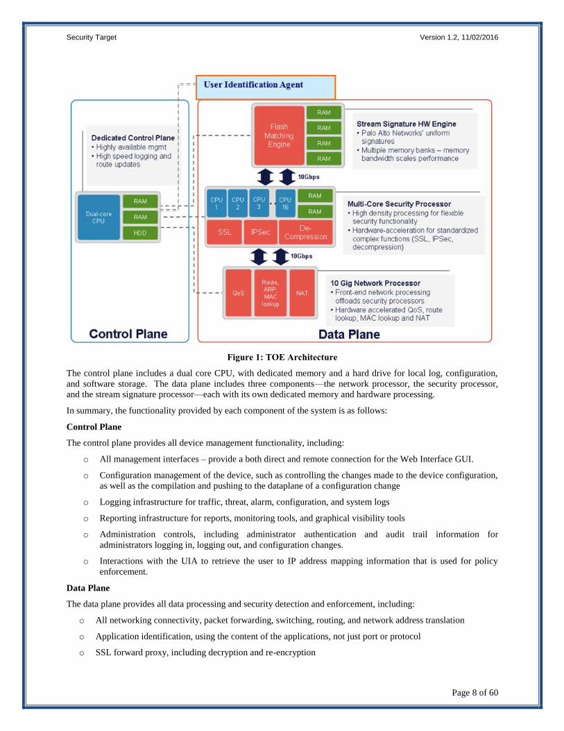
The following diagram depicts both the hardware and software architecture of the next-generation firewall. The
User Identification Agent is in the operational environment.
Page 11
Security Target Version 1.2, 11/02/2016
Page 8 of 60
Figure 1: TOE Architecture
The control plane includes a dual core CPU, with dedicated memory and a hard drive for local log, configuration,
and software storage. The data plane includes three components—the network processor, the security processor,
and the stream signature processor—each with its own dedicated memory and hardware processing.
In summary, the functionality provided by each component of the system is as follows:
Control Plane
The control plane provides all device management functionality, including:
o All management interfaces – provide a both direct and remote connection for the Web Interface GUI.
o Configuration management of the device, such as controlling the changes made to the device configuration,
as well as the compilation and pushing to the dataplane of a configuration change
o Logging infrastructure for traffic, threat, alarm, configuration, and system logs
o Reporting infrastructure for reports, monitoring tools, and graphical visibility tools
o Administration controls, including administrator authentication and audit trail information for
administrators logging in, logging out, and configuration changes.
o Interactions with the UIA to retrieve the user to IP address mapping information that is used for policy
enforcement.
Data Plane
The data plane provides all data processing and security detection and enforcement, including:
o All networking connectivity, packet forwarding, switching, routing, and network address translation
o Application identification, using the content of the applications, not just port or protocol
o SSL forward proxy, including decryption and re-encryption
Page 12
Security Target Version 1.2, 11/02/2016
Page 9 of 60
o Policy lookups to determine what security policy to enforce and what actions to take, including scanning for
threats, logging, and packet marking
o Application decoding, threat scanning for all types of threats and threat prevention
o Logging, with all logs sent to the control plane for processing and storage
The product’s SSL decryption feature uses an SSL proxy to establish itself as a man-in-the-middle proxy, which
decrypts and controls the traffic within the SSL tunnel that traverses the TOE. The SSL proxy acts as a forward
proxy (internal client to an external server). The certificates used by the TOE during forward proxying include as
much relevant data from the external server’s original certificate as possible (i.e., validity dates, certificate purpose,
common name, and subject information). For inbound connections (external client to internal server), the TOE can
decrypt incoming traffic and control the traffic within the SSL tunnel. SSL decryption is configured as a rulebase in
which match criteria include zone, IP address, and User-ID. SSL proxy is configured by creating a Certificate
Authority certificate (CA cert) on the firewall. When a client attempts to connect with a remote server, if a
decryption policy is matched, the firewall will create a connection with the server and another connection with the
client, inserting itself in the middle. The firewall will copy the subject information, validity information, and
common name into a new certificate that is signed by the CA cert. If the firewall trusts the issuer of the server’s
certificate, it will sign the newly generated server cert with a trusted CA cert. If the firewall does not trust the issuer
of the server’s certificate, it will sign the newly generated server cert with an untrusted CA cert, thereby relaying the
untrusted nature of the certificate to the client. A new public/private key pair is generated for each new SSL server
to which the client’s connect.
SSH Decryption is checked using the SSH application signature, a policy lookup will occur on the decrypt rule to
see if this session should be decrypted. If yes, the TOE will set up a man-in-the middle to decrypt the session and
decide if any port-forwarding request is sent in that session. As soon as any port forwarding is detected, the
application becomes an SSH-tunnel, and based on the policy, the session might get denied.
Site-to-site IPsec VPN supports IPv4 or IPv6 site-to-site connections. That is, you can establish IKE and IPsec
Security Associations (SAs) between IPv4 or IPv6 endpoints. The web interface can be used to enable, disable,
restart, or refresh an IKE gateway or an IPsec VPN tunnel to simplify troubleshooting.
User Identification Agent
The user identification agent is a client software program installed on one or more PCs on the protected network to
obtain user-specific information. The agent can be installed on any PC running Windows Vista, or Windows Server
2003 32bit with SP2 (or higher than SP2), or Windows Server 2008 32bit and 64bit. The agent communicates with
a Microsoft Windows Domain Controller to obtain user information (such as user groups, users, and machines
deployed in the domain) and makes the information available to the firewall, which uses it for policy enforcement
and reporting. The UIA maintains mapping information received from the Domain Controller, which it synchronizes
to the firewall table. The UIA provides the firewall with the capability to automatically collect user-specific
information, and provides mapping information between IP addresses and network users. Policy enforcement
decisions regarding whether or not a packet is allowed through the firewall are made based on the packet’s IP
addresses. The UIA allows firewall policies to be constructed using user identifiers as well as IP addresses. The
UIA enables scaling of VPN deployments and maintains mapping information received from the Domain Controller,
which it synchronizes to the firewall table. The UIA only works with IPv4 addresses and does not work with IPv6
addresses. The User Identification Agent is in the operational environment.
VM-Series
The VM-Series on specified hardware supports the exact same next-generation firewall and advanced threat
prevention features that are available in the physical form factor appliances, allowing an administrator to safely
enable applications flowing into, and across private, public and hybrid cloud computing environments.
Automation features such as VM monitoring, dynamic address groups and a REST-based API permit proactively
monitoring VM changes and dynamically feeding that context into security policies, thereby eliminating the policy
lag that may occur when your VMs change.
Each VM-Series virtual appliance in its evaluated configuration is installed on a hardware platform as specified in
Section 1.1 that includes VMware ESXi 5.5 hypervisor, an Intel Core or Xeon processor based on the Ivy Bridge or
Page 13
Security Target Version 1.2, 11/02/2016
Page 10 of 60
Haswell microarchitectures that implement Intel Secure Key, and Network Interface Controllers supported by the
Server.
2.2.1 Physical Boundaries
The TOE consists of the following components:
Hardware appliance-includes the physical port connections on the outside of the appliance cabinet and a
time clock that provides the time stamp used for the audit records.
Virtualized Firewalls installed on specified hardware - the VM-Series supports the exact same next-
generation firewall and advanced threat prevention features available in the physical form factor
appliances, allowing an administrator to safely enable applications flowing into, and across your private,
public and hybrid cloud computing environments. The VM software and the appliances are both included
in the TOE. The time clock, as well as CPU, ports, etc., are provided by VM environment (hypervisor)
hosting the PAN-OS VMs. VMs are deployed in the system using Intel CPUs.
PAN-OS v7.0.8 or v7.1.3 – the software/firmware component that runs the appliance. For VMs PAN-OS is
software and for hardware appliances PAN-OS is firmware. PAN-OS is built on top of a Linux kernel and
runs along with Appweb (the web server that Palo Alto Networks uses), crond, syslogd, and various
vendor-developed applications that implement PAN-OS capabilities. PAN-OS provides the logical
interfaces for network traffic. PAN-OS runs on both the Control Plane and the Data Plane and provides all
firewall functionalities provided by the TOE, including the threat prevention capabilities as well as the
identification and authentication of users and the management functions. PAN-OS provides unique
functionality on the two planes based on the applications that are executing. The Control Plane provides a
GUI Web management interface to access and manage the TOE functions and data. The Data Plane
provides the external interface between the TOE and the external network to monitor network traffic so that
the TSF can enforce the TSF security policy.
The physical boundary of the TOE comprises the firewall appliance (PA-200, PA-500, PA-2020, PA-2050, PA-
3020, PA-3050, PA-3060, PA-4020, PA-4050, PA-4060, PA-5020, PA-5050, PA-5060, PA-7050, PA-7080); and
the virtual appliances on specified hardware in the VM-Series VM-100, VM-200, VM-300, VM-1000-HV. The
next-generation firewall models differ in their performance capability, but they provide the same security
functionality.
Virtualized systems are supported by default (without an additional license) on the PA-500, PA-2020, PA-2050, PA-
3020, PA-3050, PA-3060, PA-4020, PA-4050, PA-4060, PA-5020, PA-5050, PA-5060, PA-7050, and PA-7080.
The PA-200 cannot support virtual systems. Virtual systems specify a collection of physical and logical firewall
interfaces that should be isolated. Each virtual system contains its own security policy and its own set of logs that
will be kept separate from all other virtual systems.
The firewall appliance attaches to a physical network and includes the following ports:
PA-200: 8 RJ-45 10/100/1000 ports for network traffic (Ethernet ports); 1 RJ-45 port to access the device
GUI through an Ethernet interface (management ports); and 1 RJ-45 port for connecting a serial console
(management console port)
PA-500: 8 RJ-45 10/100/1000 ports for network traffic (Ethernet ports); 1 RJ-45 port to access the device
GUI through an Ethernet interface (management ports); and 1 RJ-45 port for connecting a serial console
(management console port)
PA-2020: 12 RJ-45 10/100/1000 ports for network traffic (Ethernet ports); 2 Small Form-Factor Pluggable
(SFP) Gbps ports for network traffic, 1 RJ-45 port to access the device GUI through an Ethernet interface
(management ports); and 1 RJ-45 port for connecting a serial console (management console port)
PA-2050: 16 RJ-45 10/100/1000 ports for network traffic (Ethernet ports); 4 Small Form-Factor Pluggable
(SFP) Gbps ports for network traffic, 1 RJ-45 port to access the device GUI through an Ethernet interface
(management ports); and 1 RJ-45 port for connecting a serial console (management console port)
PA-3020/PA-3050: 12 RJ-45 10/100/1000 ports for network traffic (Ethernet ports); 8 Small Form-Factor
Pluggable (SFP) Gbps ports for network traffic, 1 RJ-45 port to access the device GUI through an Ethernet
Page 14
Security Target Version 1.2, 11/02/2016
Page 11 of 60
interface (management ports); 1 RJ-45 port for connecting a serial console (management console port); and
2 RJ-45 ports for high-availability (HA) control and synchronization
PA-3060: 8 RJ-45 10/100/1000 ports for network traffic (Ethernet ports); 8 Small Form-Factor Pluggable
(SFP) Gbps ports for network traffic, 1 RJ-45 port to access the device GUI through an Ethernet interface
(management ports); 1 RJ-45 port for connecting a serial console (management console port); and 2 RJ-45
ports for high-availability (HA) control and synchronization.
PA-4020/4050: 16 RJ-45 10/100/1000 ports for network traffic (Ethernet ports); 8 Small Form-Factor
Pluggable (GFP) Mbps ports for network traffic, 1 RJ-45 port to access the device GUI through an Ethernet
interface (management ports); 1 DB-9 port for connecting a serial console (management console port); and
2 RJ-45 ports for high-availability (HA) control and synchronization
PA-4060: 4 XFP 10 Gbps ports for management traffic; 4 Small Form-Factor Pluggable (SFP) Mbps ports
for network traffic, 1 RJ-45 port to access the device CLI or GUI through an Ethernet interface
(management ports); 1 DB-9 port for connecting a serial console (management console port); and 2 RJ-45
ports for high-availability (HA) control and synchronization
PA-5020: 12 RJ-45 10/100/1000 ports for network traffic. 8 Small Form-Factor Pluggable (SFP) ports for
network traffic. One RJ-45 port to access the device management interfaces through an Ethernet interface.
One RJ-45 port for connecting a serial console. Two RJ-45 ports for high-availability (HA) control and
synchronization.
PA-5050: 12 RJ-45 10/100/1000 ports for network traffic. Eight Small Form-Factor Pluggable (SFP) ports
for network traffic. Four SFP+ ports for network traffic. One RJ-45 port to access the device management
interfaces through an Ethernet interface. One RJ-45 port for connecting a serial console. Two RJ-45 ports
for high-availability (HA) control and synchronization.
PA-5060: 12 RJ-45 10/100/1000 ports for network traffic. Eight Small Form-Factor Pluggable (SFP) ports
for network traffic. Four SFP+ ports for network traffic. One RJ-45 port to access the device management
interfaces through an Ethernet interface. One RJ-45 port for connecting a serial console. Two RJ-45 ports
for high-availability (HA) control and synchronization.
PA-7050: 12 gig copper ports for network traffic, eight Small Form-Factor Pluggable (SFP) ports for
network traffic and four SFP+ ports for network traffic per blade OR two Quad Small Form-Factor
Pluggable (QSFP) for network traffic per blade and twelve SFP+ ports for network traffic per blade (6
blades max). One RJ-45 port to access the device management interfaces through an Ethernet interface.
One RJ-45 port for connecting a serial console. Two QSFP ports for high-availability (HA) control and
synchronization.
PA-7080: 12 gig copper ports for network traffic, eight Small Form-Factor Pluggable (SFP) ports for
network traffic and four SFP+ ports for network traffic per blade OR two Quad Small Form-Factor
Pluggable (QSFP) for network traffic per blade and twelve SFP+ ports for network traffic per blade (10
blades max). One RJ-45 port to access the device management interfaces through an Ethernet interface.
One RJ-45 port for connecting a serial console. Two QSFP ports for high-availability (HA) control and
synchronization.
In the evaluated configuration, the TOE can be managed by:
A computer either directly connected or remotely connected to the Management port via an RJ-45 Ethernet
cable. The Management port is an out-of-band management port that provides access to the GUI via
HTTPS. The computer is part of the operational environment and required to have a web browser (for
accessing the GUI).
Traffic logs, which record information about each traffic flow or problems with the network traffic, are logged
locally by default. However, the product offers the capability to send the logs as SNMP traps, Syslog messages, or
email notifications. Traffic logging and the use of email notifications and the SNMP and SMTP servers have not
been subject to testing in the evaluated configuration.
The operational environment includes a syslog server, update server, and VPN gateway peer(s).
Page 15
Security Target Version 1.2, 11/02/2016
Page 12 of 60
The operational environment includes a domain controller and the User Identification Agent is installed on one or
more PCs in the operational environment, and is supported on Windows XP with SP2 (or higher than SP2), or
Windows Vista, or Windows Server 2003 32bit with SP2 (or higher than SP2), or Windows Server 2008 32bit and
64bit.
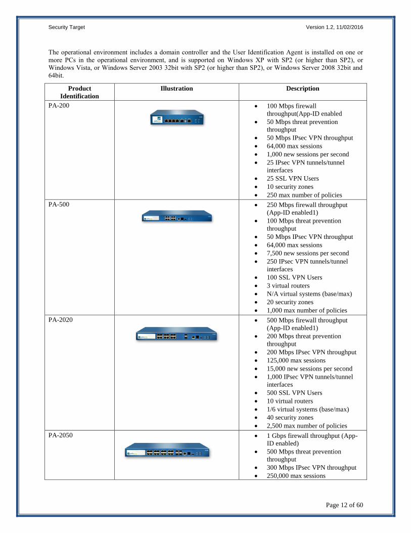
Product
Identification
Illustration Description
PA-200
100 Mbps firewall
throughput(App-ID enabled
50 Mbps threat prevention
throughput
50 Mbps IPsec VPN throughput
64,000 max sessions
1,000 new sessions per second
25 IPsec VPN tunnels/tunnel
interfaces
25 SSL VPN Users
10 security zones
250 max number of policies
PA-500
250 Mbps firewall throughput
(App-ID enabled1)
100 Mbps threat prevention
throughput
50 Mbps IPsec VPN throughput
64,000 max sessions
7,500 new sessions per second
250 IPsec VPN tunnels/tunnel
interfaces
100 SSL VPN Users
3 virtual routers
N/A virtual systems (base/max)
20 security zones
1,000 max number of policies
PA-2020
500 Mbps firewall throughput
(App-ID enabled1)
200 Mbps threat prevention
throughput
200 Mbps IPsec VPN throughput
125,000 max sessions
15,000 new sessions per second
1,000 IPsec VPN tunnels/tunnel
interfaces
500 SSL VPN Users
10 virtual routers
1/6 virtual systems (base/max)
40 security zones
2,500 max number of policies
PA-2050
1 Gbps firewall throughput (App-
ID enabled)
500 Mbps threat prevention
throughput
300 Mbps IPsec VPN throughput
250,000 max sessions
Page 16
Security Target Version 1.2, 11/02/2016
Page 13 of 60
15,000 new sessions per second
2,000 IPsec VPN tunnels/tunnel
interfaces
1,000 SSL VPN Users
10 virtual routers
1/6 virtual systems (base/max)
40 security zones
5,000 max number of policies
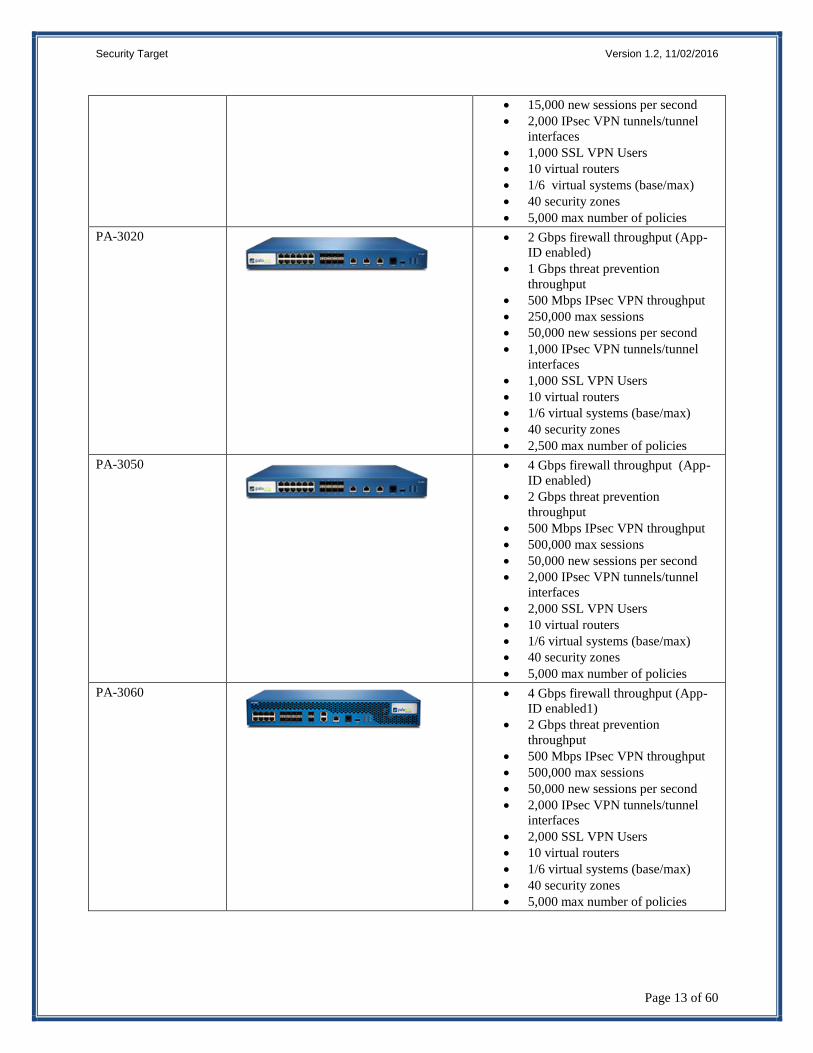
PA-3020
2 Gbps firewall throughput (App-
ID enabled)
1 Gbps threat prevention
throughput
500 Mbps IPsec VPN throughput
250,000 max sessions
50,000 new sessions per second
1,000 IPsec VPN tunnels/tunnel
interfaces
1,000 SSL VPN Users
10 virtual routers
1/6 virtual systems (base/max)
40 security zones
2,500 max number of policies
PA-3050
4 Gbps firewall throughput (App-
ID enabled)
2 Gbps threat prevention
throughput
500 Mbps IPsec VPN throughput
500,000 max sessions
50,000 new sessions per second
2,000 IPsec VPN tunnels/tunnel
interfaces
2,000 SSL VPN Users
10 virtual routers
1/6 virtual systems (base/max)
40 security zones
5,000 max number of policies
PA-3060
4 Gbps firewall throughput (App-
ID enabled1)
2 Gbps threat prevention
throughput
500 Mbps IPsec VPN throughput
500,000 max sessions
50,000 new sessions per second
2,000 IPsec VPN tunnels/tunnel
interfaces
2,000 SSL VPN Users
10 virtual routers
1/6 virtual systems (base/max)
40 security zones
5,000 max number of policies
Page 17
Security Target Version 1.2, 11/02/2016
Page 14 of 60
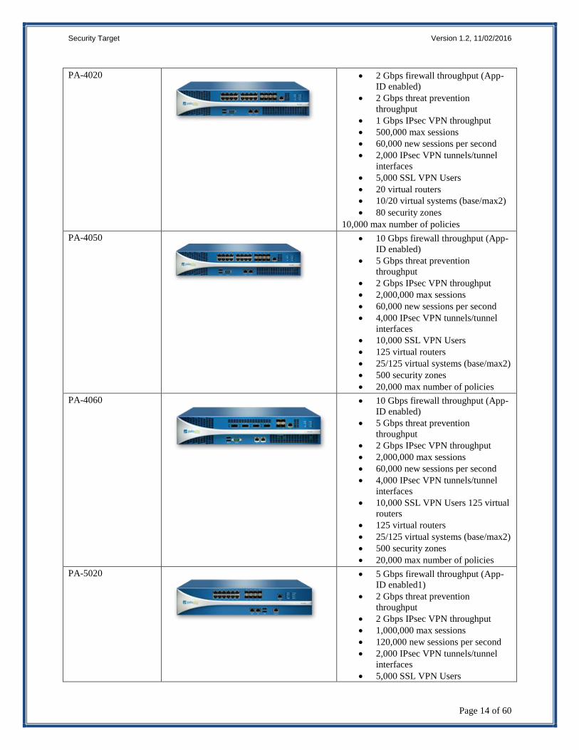
PA-4020
2 Gbps firewall throughput (App-
ID enabled)
2 Gbps threat prevention
throughput
1 Gbps IPsec VPN throughput
500,000 max sessions
60,000 new sessions per second
2,000 IPsec VPN tunnels/tunnel
interfaces
5,000 SSL VPN Users
20 virtual routers
10/20 virtual systems (base/max2)
80 security zones
10,000 max number of policies
PA-4050
10 Gbps firewall throughput (App-
ID enabled)
5 Gbps threat prevention
throughput
2 Gbps IPsec VPN throughput
2,000,000 max sessions
60,000 new sessions per second
4,000 IPsec VPN tunnels/tunnel
interfaces
10,000 SSL VPN Users
125 virtual routers
25/125 virtual systems (base/max2)
500 security zones
20,000 max number of policies
PA-4060
10 Gbps firewall throughput (App-
ID enabled)
5 Gbps threat prevention
throughput
2 Gbps IPsec VPN throughput
2,000,000 max sessions
60,000 new sessions per second
4,000 IPsec VPN tunnels/tunnel
interfaces
10,000 SSL VPN Users 125 virtual
routers
125 virtual routers
25/125 virtual systems (base/max2)
500 security zones
20,000 max number of policies
PA-5020
5 Gbps firewall throughput (App-
ID enabled1)
2 Gbps threat prevention
throughput
2 Gbps IPsec VPN throughput
1,000,000 max sessions
120,000 new sessions per second
2,000 IPsec VPN tunnels/tunnel
interfaces
5,000 SSL VPN Users
Page 18
Security Target Version 1.2, 11/02/2016
Page 15 of 60
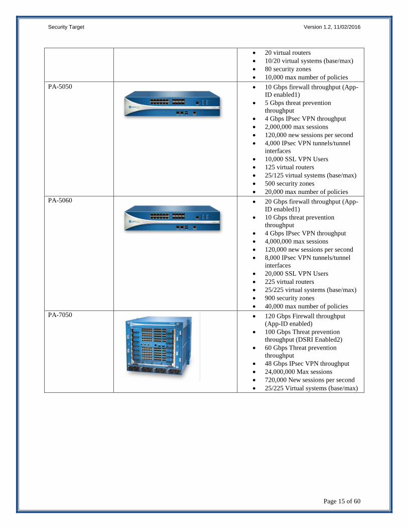
20 virtual routers
10/20 virtual systems (base/max)
80 security zones
10,000 max number of policies
PA-5050
10 Gbps firewall throughput (App-
ID enabled1)
5 Gbps threat prevention
throughput
4 Gbps IPsec VPN throughput
2,000,000 max sessions
120,000 new sessions per second
4,000 IPsec VPN tunnels/tunnel
interfaces
10,000 SSL VPN Users
125 virtual routers
25/125 virtual systems (base/max)
500 security zones
20,000 max number of policies
PA-5060
20 Gbps firewall throughput (App-
ID enabled1)
10 Gbps threat prevention
throughput
4 Gbps IPsec VPN throughput
4,000,000 max sessions
120,000 new sessions per second
8,000 IPsec VPN tunnels/tunnel
interfaces
20,000 SSL VPN Users
225 virtual routers
25/225 virtual systems (base/max)
900 security zones
40,000 max number of policies
PA-7050
120 Gbps Firewall throughput
(App-ID enabled)
100 Gbps Threat prevention
throughput (DSRI Enabled2)
60 Gbps Threat prevention
throughput
48 Gbps IPsec VPN throughput
24,000,000 Max sessions
720,000 New sessions per second
25/225 Virtual systems (base/max)
Page 19
Security Target Version 1.2, 11/02/2016
Page 16 of 60
PA-7080
200 Gbps Firewall throughput
(App-ID enabled)
160 Gbps Threat prevention
throughput (DSRI Enabled2)
100 Gbps Threat prevention
throughput
80 Gbps IPsec VPN throughput
40,000,000 Max sessions
1,200,000 New sessions per second
25/225 Virtual systems (base/max)
Virtual Appliances
VM-100 50,000 max sessions
25 IPsec VPN tunnels/tunnel
interfaces
25 SSL VPN Users
10 security zones
250 max number of policies
2,500 address objects
1Gbps Firewall Throughput (App-
ID enabled)
600 Mbps Threat Prevention
Throughput
250 Mbps IPsec VPN Throughput
8,000 New sessions per second
VM-200 100,000 max sessions
500 IPsec VPN tunnels/tunnel
interfaces
200 SSL VPN Users
20 security zones
2,000 max number of policies
4,000 address objects
1Gbps Firewall Throughput (App-
ID enabled)
600 Mbps Threat Prevention
Throughput
250 Mbps IPsec VPN Throughput
8,000 New sessions per second
VM-300 250,000 max sessions
2,000 IPsec VPN tunnels/tunnel
interfaces
500 SSL VPN Users
40 security zones
5,000 max number of policies
10,000 address objects
1Gbps Firewall Throughput (App-
ID enabled)
600 Mbps Threat Prevention
Throughput
250 Mbps IPsec VPN Throughput
8,000 New sessions per second
Page 20
Security Target Version 1.2, 11/02/2016
Page 17 of 60
VM-1000-HV 250,000 max sessions
2,000 IPsec VPN tunnels/tunnel
interfaces
500 SSL VPN Users
40 security zones
10,000 max number of policies
10,000 address objects
1Gbps Firewall Throughput (App-
ID enabled)
600 Mbps Threat Prevention
Throughput
250 Mbps IPsec VPN Throughput
8,000 New sessions per second
2.2.2 Logical Boundaries
This section summarizes the security functions provided by the TOE:
Security audit
Cryptographic support
User data protection
Identification and authentication
Security management
Protection of the TSF
TOE access
Trusted path/channels
Stateful traffic filtering
Packet filtering
2.2.2.1 Security audit
The TOE is designed to be able to generate logs for a wide range of security relevant events including the events
specified in NDPP. The TOE can be configured to store the logs locally so they can be accessed by an administrator
and can also be configured to send the logs to a designated external log server.
2.2.2.2 Cryptographic support
The TOE implements NIST-validated cryptographic algorithms that provide key management, random bit
generation, encryption/decryption, digital signature and cryptographic hashing and keyed-hash message
authentication features in support of higher level cryptographic protocols, including IPsec and TLS. Note that to be
in the evaluated configuration, the TOE must be configured in Common Criteria mode, which ensures the TOE’s
configuration is consistent with the FIPS 140-2 standard. All physical and virtual appliance included in the TOE are
FIPS 140-2 validated, as follows:
The PA-200, PA-500, PA-2000 Series, PA-3000 Series (except the PA-3060), PA-4000 Series, PA-5000
Series and PA-7050 Firewall appliances with PAN-OS 7.0.8 are covered by CMVP certificate #2637
The PA-3060 and PA-7080 Firewall appliances with PAN-OS 7.0.8 are covered by CMVP certificate
#2616
The Palo Alto Networks VM-Series virtual appliances with PAN-OS 7.0.8 are covered by CMVP
certificate #2620
The PA-200, PA-500, PA-2000 Series, PA-3000 Series (except the PA-3060), PA-4000 Series, PA-5000
Series and PA-7050 Firewall appliances with PAN-OS 7.1.3 are covered by CMVP certificate #2799
Page 21
Security Target Version 1.2, 11/02/2016
Page 18 of 60
The PA-3060 and PA-7080 Firewall appliances with PAN-OS 7.1.3 are covered by CMVP certificate
#2797
The Palo Alto Networks VM-Series virtual appliances with PAN-OS 7.1.3 are covered by CMVP
certificate #2800.
2.2.2.3 User data protection
The TOE is designed to ensure that it does not inadvertently reuse data found in network traffic.
2.2.2.4 Identification and authentication
The TOE requires all users accessing the TOE user interfaces to be successfully identified and authenticated before
they can access any security management functions available in the TOE. The TOE offers network accessible
(HTTP over TLS) and direct connections to the GUI for interactive administrator sessions.
The TOE supports the local (i.e., on device) definition and authentication of administrators with username,
password, and role (set of privileges), which it uses to authenticate the human user and to associate that user with an
authorized role. In addition, the TOE can authenticate users using X509 certificates and can be configured to lock a
user out after a configurable number of unsuccessful authentication attempts.
2.2.2.5 Security management
The TOE provides a GUI to access the wide range of security management functions. Security management
commands are limited to administrators and are available only after they have provided acceptable user
identification and authentication data to the TOE. The TOE provides access to the GUI locally via direct RJ-45
Ethernet cable connection and remotely using an HTTPS/TLS client.
The TOE provides a number of management functions and restricts them to users with the appropriate privileges.
The management functions include the capability to create new user accounts, configure the audit function,
configure the information flow control rules, and review the audit trail. The TOE provides pre-defined Security
Administrator, Audit Administrator, and Cryptographic Administrator roles. These administrator roles are all
considered Security Administrator as defined in the NDPP for the purposes of this ST.
2.2.2.6 Protection of the TSF
The TOE implements a number of features designed to protect itself to ensure the reliability and integrity of its
security features.
It protects particularly sensitive data such as stored passwords and cryptographic keys so that they are not accessible
even by an administrator. It also provides its own timing mechanism to ensure that reliable time information is
available (e.g., for log accountability).
The TOE includes functions to perform self-tests so that it might detect when it is failing. It also includes
mechanisms so that the TOE itself can be updated while ensuring that the updates will not introduce malicious or
other unexpected changes in the TOE.
2.2.2.7 TOE access
The TOE provides the capabilities for both TOE- and user-initiated locking of interactive sessions and for TOE
termination of an interactive session after a period of inactivity. The TOE will display an advisory and consent
warning message regarding unauthorized use of the TOE before establishing a user session.
2.2.2.8 Trusted path/channels
The TOE protects interactive communication with remote administrators using IPsec or HTTP over TLS. IPsec and
TLS ensures both integrity and disclosure protection.
The TOE protects communication with the UIA, update server using TLS connections; the external log server with
IPsec or TLS, and remote VPN gateways/peers using IPsec to prevent unintended disclosure or modification of the
transferred data.
Page 22
Security Target Version 1.2, 11/02/2016
Page 19 of 60
2.2.2.9 Stateful traffic filtering
The TOE provides a stateful traffic filter firewall for layers 3 and 4 (IP and TCP/UDP) network traffic optimized
through the use of stateful packet inspection.
An administrator can configure the TOE to control the type of information that is allowed to pass through the TOE.
The administrator defines the security zone and applies security policies to network traffic attempting to traverse the
TOE to determine what actions to take.
The TOE groups interfaces into security zones. Each zone identifies one or more interfaces on the TOE. Separate
zones must be created for each type of interface (Layer 2, Layer 3, or virtual wire), and each interface must be
assigned to a zone before it can process traffic. Security policies provide the firewall rule sets that specify whether
to block or allow network connections, based on the source and destination zones, and addresses, and the application
service (such as UDP port 67 or TCP port 80). Security policy rules are processed in sequence, applying the first
rule that matches the incoming traffic.
2.2.2.10 Packet filtering
The TOE provides packet filtering and secure IPsec tunneling. The tunnels can be established between two trusted
VPN peers as well as between remote VPN clients and the TOE. An administrator can configure security policies
that determine whether to block, allow, or log a session based on traffic attributes such as the source and destination
security zone, the source and destination IP address, the application, user, and the service.
2.3 TOE Documentation
Palo Alto Networks Inc. offers a series of documents that describe the installation of Palo Alto Networks next-
generation firewalls as well as guidance for subsequent use and administration of the applicable security features.
For PAN-OS v7.0.8, these documents include:
Palo Alto Networks Common Criteria Evaluated Configuration Guide (CCECG) for PAN-OS v7.0,
Version 1.1, 9 September 2016
Palo Alto Networks PAN-OS Administrator’s Guide Version 7.0
Palo Alto Networks Web Interface Reference Guide, Version 7.0.
For PAN-OS v7.1.3, these documents include:
Palo Alto Networks Common Criteria Evaluated Configuration Guide (CCECG) for PAN-OS v7.1,
Version 1.0, 9 September 2016
Palo Alto Networks PAN-OS Administrator’s Guide Version 7.1
Palo Alto Networks Web Interface Reference Guide, Version 7.1.
Page 23
Security Target Version 1.2, 11/02/2016
Page 20 of 60
3. Security Problem Definition
This security target includes by reference the Security Problem Definition (composed of organizational policies,
threat statements, and assumption) from NDPP, STFF and VPNGW.
In general, the NDPP has presented a Security Problem Definition appropriate for network infrastructure devices,
such as firewalls, and as such is applicable to the Palo Alto TOE. Likewise, the STFF has presented a Security
Problem definition appropriate for Stateful Traffic Filter Firewalls; and the VPNGW has presented a Security
Problem definition appropriate for VPN Gateways, as such both are applicable to the Palo Alto TOE.
Page 24
Security Target Version 1.2, 11/02/2016
Page 21 of 60
4. Security Objectives
Like the Security Problem Definition, this security target includes by reference the Security Objectives from the
NDPP, STFF, and the VPNGW. The security objectives for the operational environment are reproduced below,
since these objectives characterize technical and procedural measures each consumer must implement in their
operational environment.
In general, the NDPP, STFF, and the VPNGW have presented Security Objectives appropriate for network
infrastructure devices, such as firewalls, Stateful Traffic Filter Firewalls, and VPN Gateways and as such are
applicable to the Palo Alto TOE.
4.1 Security Objectives for the Operational Environment
OE.NO_GENERAL_PURPOSE There are no general-purpose computing capabilities (e.g.,
compilers or user applications) available on the TOE, other
than those services necessary for the operation, administration
and support of the TOE.
OE.PHYSICAL Physical security, commensurate with the value of the TOE
and the data it contains, is provided by the environment.
OE.TRUSTED_ADMIN TOE Administrators are trusted to follow and apply all
administrator guidance in a trusted manner.
OE.CONNECTIONS TOE administrators will ensure that the TOE is installed in a
manner that will allow the TOE to effectively enforce its
policies on network traffic flowing among attached networks.
Page 25
Security Target Version 1.2, 11/02/2016
Page 22 of 60
5. IT Security Requirements
This section defines the Security Functional Requirements (SFRs) and Security Assurance Requirements (SARs)
that serve to represent the security functional claims for the Target of Evaluation (TOE) and to scope the evaluation
effort.
The SFRs have all been drawn from the Protection Profile (PP): Protection Profile for Network Devices, Version
1.1, 8 June 2012 (NDPP), as amended by Errata #3, Network Device Protection Profile (NDPP) Extended Package
Stateful Traffic Filter Firewall, Version 1.0, 19 December 2011 (STFF), and the Network Device Protection Profile
(NDPP) Extended Package VPN Gateway, Version 1.1, 12 April 2013 (VPNGW). As a result, refinements and
operations already performed in that PP are not identified (e.g., highlighted) here, rather the requirements have been
copied from that PP and any residual operations have been completed herein. Of particular note, the NDPP made a
number of refinements and completed some of the SFR operations defined in the CC and that PP should be
consulted to identify those changes if necessary.
The SARs are the set of SARs specified in NDPP, STFF, and VPNGW.
5.1 Extended Requirements
All of the extended requirements in this ST have been drawn from the NDPP, STFF, and VPNGW. The NDPP,
STFF, and VPNGW define the following extended SFRs and since they are not redefined in this ST, the NDPP,
STFF, and VPNGW should be consulted for more information in regard to those CC extensions.
FAU_STG_EXT.1: External Audit Trail Storage
FCS_CKM_EXT.4: Cryptographic Key Zeroization
FCS_HTTPS_EXT.1: Explicit: HTTPS
FCS_IPSEC_EXT.1: Explicit: IPSEC
FCS_RBG_EXT.1: Extended: Cryptographic Operation (Random Bit Generation)
FCS_TLS_EXT.1: Explicit: TLS
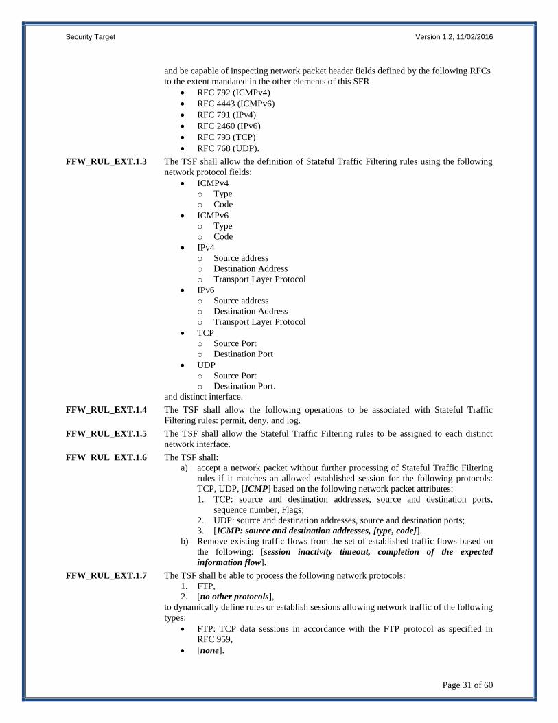
FFW_RUL_EXT.1 Stateful Traffic Filtering
FIA_PMG_EXT.1: Password Management
FIA_UAU_EXT.2: Extended: Password-based Authentication Mechanism
FIA_UIA_EXT.1: User Identification and Authentication
FIA_X509_EXT.1 Extended: X.509 Certificates
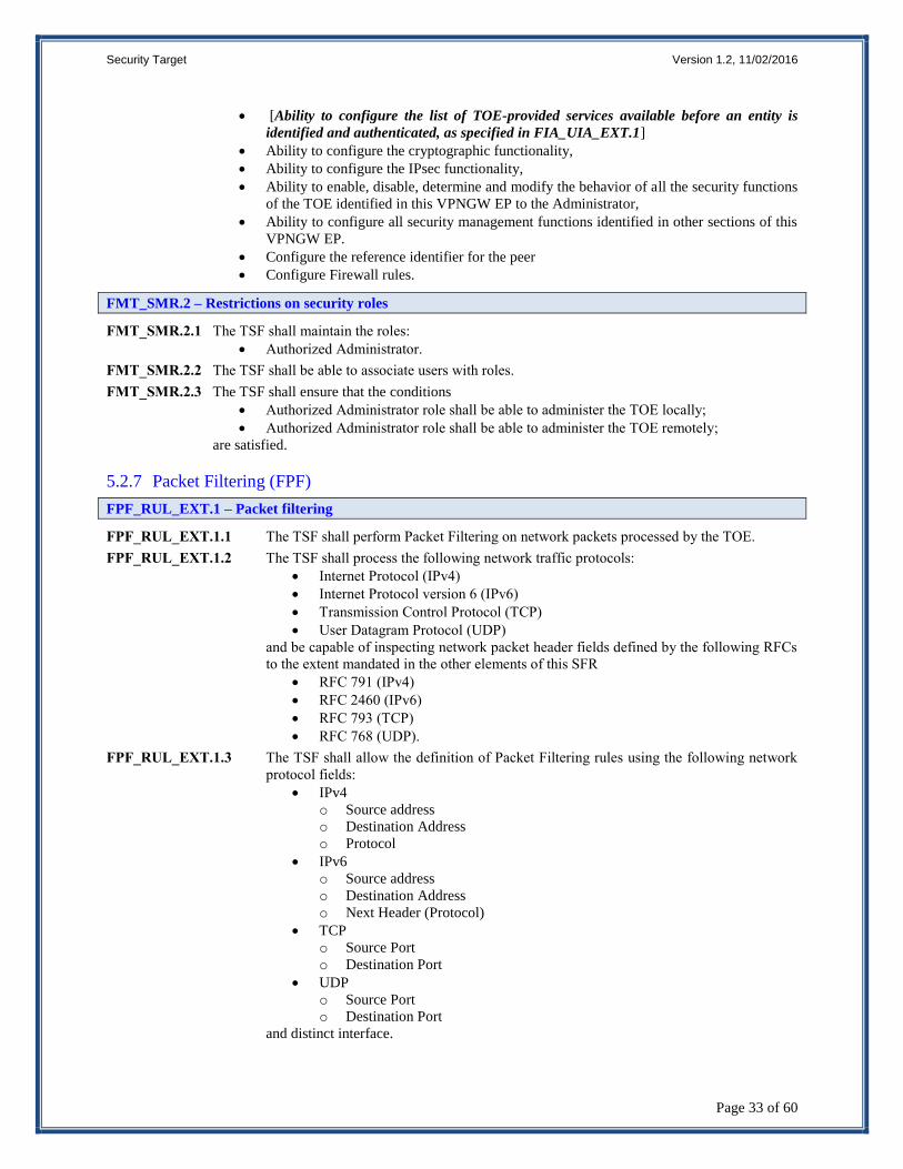
FPF_RUL_EXT.1 Packet Filtering
FPT_APW_EXT.1: Extended: Protection of Administrator Passwords
FPT_SKP_EXT.1: Extended: Protection of TSF Data (for reading of all symmetric keys)
FPT_TST_EXT.1: TSF Testing
FPT_TUD_EXT.1: Extended: Trusted Update
FTA_SSL_EXT.1: TSF-initiated Session Locking
Page 26
Security Target Version 1.2, 11/02/2016
Page 23 of 60
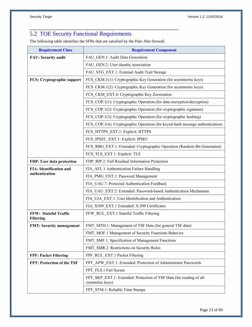
5.2 TOE Security Functional Requirements
The following table identifies the SFRs that are satisfied by the Palo Alto firewall.
Requirement Class Requirement Component
FAU: Security audit
FAU_GEN.1: Audit Data Generation
FAU_GEN.2: User identity association
FAU_STG_EXT.1: External Audit Trail Storage
FCS: Cryptographic support
FCS_CKM.1(1): Cryptographic Key Generation (for asymmetric keys)
FCS_CKM.1(2): Cryptographic Key Generation (for asymmetric keys)
FCS_CKM_EXT.4: Cryptographic Key Zeroization
FCS_COP.1(1): Cryptographic Operation (for data encryption/decryption)
FCS_COP.1(2): Cryptographic Operation (for cryptographic signature)
FCS_COP.1(3): Cryptographic Operation (for cryptographic hashing)
FCS_COP.1(4): Cryptographic Operation (for keyed-hash message authentication)
FCS_HTTPS_EXT.1: Explicit: HTTPS
FCS_IPSEC_EXT.1: Explicit: IPSEC
FCS_RBG_EXT.1: Extended: Cryptographic Operation (Random Bit Generation)
FCS_TLS_EXT.1: Explicit: TLS
FDP: User data protection FDP_RIP.2: Full Residual Information Protection
FIA: Identification and
authentication
FIA_AFL.1 Authentication Failure Handling
FIA_PMG_EXT.1: Password Management
FIA_UAU.7: Protected Authentication Feedback
FIA_UAU_EXT.2: Extended: Password-based Authentication Mechanism
FIA_UIA_EXT.1: User Identification and Authentication
FIA_X509_EXT.1 Extended: X.509 Certificates
FFW: Stateful Traffic
Filtering
FFW_RUL_EXT.1 Stateful Traffic Filtering
FMT: Security management
FMT_MTD.1: Management of TSF Data (for general TSF data)
FMT_MOF.1 Management of Security Functions Behavior
FMT_SMF.1: Specification of Management Functions
FMT_SMR.2: Restrictions on Security Roles
FPF: Packet Filtering FPF_RUL_EXT.1 Packet Filtering
FPT: Protection of the TSF FPT_APW_EXT.1: Extended: Protection of Administrator Passwords
FPT_FLS.1 Fail Secure
FPT_SKP_EXT.1: Extended: Protection of TSF Data (for reading of all
symmetric keys)
FPT_STM.1: Reliable Time Stamps
Page 27
Security Target Version 1.2, 11/02/2016
Page 24 of 60
Requirement Class Requirement Component
FPT_TST_EXT.1: TSF Testing
FPT_TUD_EXT.1: Extended: Trusted Update
FTA: TOE access
FTA_SSL.3: TSF-initiated Termination
FTA_SSL.4: User-initiated Termination
FTA_SSL_EXT.1: TSF-initiated Session Locking
FTA_TAB.1: Default TOE Access Banners
FTP: Trusted path/channels
FTP_ITC.1: Trusted Channel
FTP_TRP.1: Trusted Path
Table 1 TOE Security Functional Components
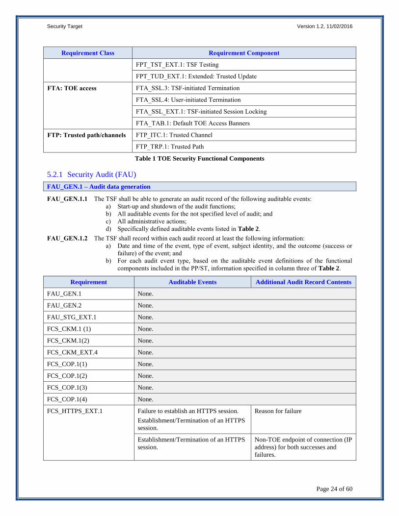
5.2.1 Security Audit (FAU)
FAU_GEN.1 – Audit data generation
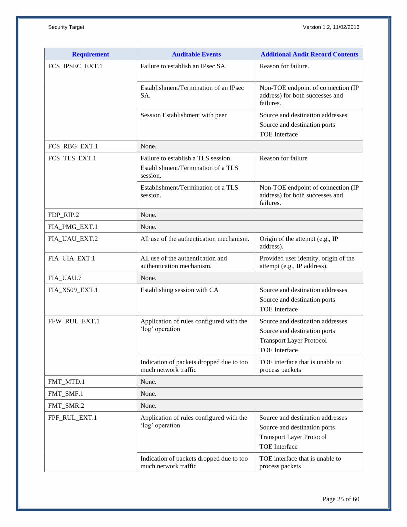
FAU_GEN.1.1 The TSF shall be able to generate an audit record of the following auditable events:
a) Start-up and shutdown of the audit functions;
b) All auditable events for the not specified level of audit; and
c) All administrative actions;
d) Specifically defined auditable events listed in Table 2.
FAU_GEN.1.2 The TSF shall record within each audit record at least the following information:
a) Date and time of the event, type of event, subject identity, and the outcome (success or
failure) of the event; and
b) For each audit event type, based on the auditable event definitions of the functional
components included in the PP/ST, information specified in column three of Table 2.
Requirement Auditable Events Additional Audit Record Contents
FAU_GEN.1 None.
FAU_GEN.2 None.
FAU_STG_EXT.1 None.
FCS_CKM.1 (1) None.
FCS_CKM.1(2) None.
FCS_CKM_EXT.4 None.
FCS_COP.1(1) None.
FCS_COP.1(2) None.
FCS_COP.1(3) None.
FCS_COP.1(4) None.
FCS_HTTPS_EXT.1 Failure to establish an HTTPS session.
Establishment/Termination of an HTTPS
session.
Reason for failure
Establishment/Termination of an HTTPS
session.
Non-TOE endpoint of connection (IP
address) for both successes and
failures.
Page 28
Security Target Version 1.2, 11/02/2016
Page 25 of 60
Requirement Auditable Events Additional Audit Record Contents
FCS_IPSEC_EXT.1 Failure to establish an IPsec SA.
Reason for failure.
Establishment/Termination of an IPsec
SA.
Non-TOE endpoint of connection (IP
address) for both successes and
failures.
Session Establishment with peer Source and destination addresses
Source and destination ports
TOE Interface
FCS_RBG_EXT.1 None.
FCS_TLS_EXT.1 Failure to establish a TLS session.
Establishment/Termination of a TLS
session.
Reason for failure
Establishment/Termination of a TLS
session.
Non-TOE endpoint of connection (IP
address) for both successes and
failures.
FDP_RIP.2 None.
FIA_PMG_EXT.1 None.
FIA_UAU_EXT.2 All use of the authentication mechanism. Origin of the attempt (e.g., IP
address).
FIA_UIA_EXT.1 All use of the authentication and
authentication mechanism.
Provided user identity, origin of the
attempt (e.g., IP address).
FIA_UAU.7 None.
FIA_X509_EXT.1 Establishing session with CA Source and destination addresses
Source and destination ports
TOE Interface
FFW_RUL_EXT.1 Application of rules configured with the
‘log’ operation
Source and destination addresses
Source and destination ports
Transport Layer Protocol
TOE Interface
Indication of packets dropped due to too
much network traffic
TOE interface that is unable to
process packets
FMT_MTD.1 None.
FMT_SMF.1 None.
FMT_SMR.2 None.
FPF_RUL_EXT.1 Application of rules configured with the
‘log’ operation
Source and destination addresses
Source and destination ports
Transport Layer Protocol
TOE Interface
Indication of packets dropped due to too
much network traffic
TOE interface that is unable to
process packets
Page 29
Security Target Version 1.2, 11/02/2016
Page 26 of 60
Requirement Auditable Events Additional Audit Record Contents
FPT_APW_EXT.1 None.
FPT_SKP_EXT.1 None.
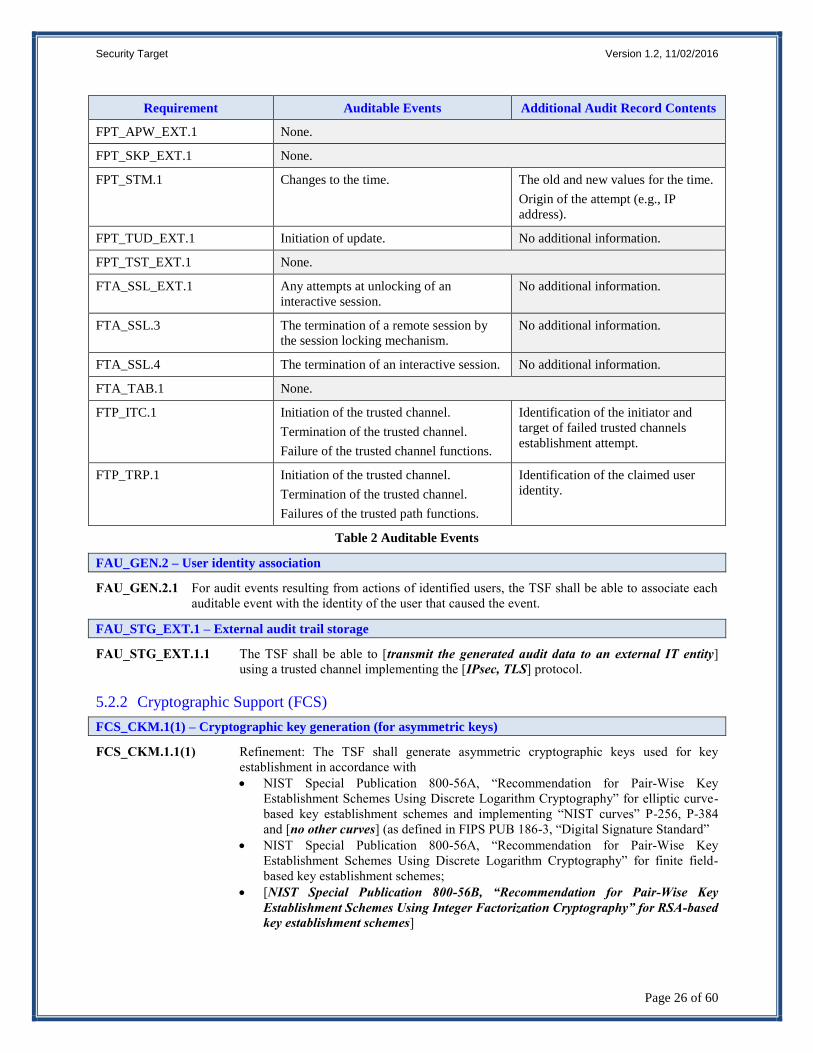
FPT_STM.1 Changes to the time. The old and new values for the time.
Origin of the attempt (e.g., IP
address).
FPT_TUD_EXT.1 Initiation of update. No additional information.
FPT_TST_EXT.1 None.
FTA_SSL_EXT.1 Any attempts at unlocking of an
interactive session.
No additional information.
FTA_SSL.3 The termination of a remote session by
the session locking mechanism.
No additional information.
FTA_SSL.4 The termination of an interactive session. No additional information.
FTA_TAB.1 None.
FTP_ITC.1 Initiation of the trusted channel.
Termination of the trusted channel.
Failure of the trusted channel functions.
Identification of the initiator and
target of failed trusted channels
establishment attempt.
FTP_TRP.1 Initiation of the trusted channel.
Termination of the trusted channel.
Failures of the trusted path functions.
Identification of the claimed user
identity.
Table 2 Auditable Events
FAU_GEN.2 – User identity association
FAU_GEN.2.1 For audit events resulting from actions of identified users, the TSF shall be able to associate each
auditable event with the identity of the user that caused the event.
FAU_STG_EXT.1 – External audit trail storage
FAU_STG_EXT.1.1 The TSF shall be able to [transmit the generated audit data to an external IT entity]
using a trusted channel implementing the [IPsec, TLS] protocol.
5.2.2 Cryptographic Support (FCS)
FCS_CKM.1(1) – Cryptographic key generation (for asymmetric keys)
FCS_CKM.1.1(1) Refinement: The TSF shall generate asymmetric cryptographic keys used for key
establishment in accordance with
NIST Special Publication 800-56A, “Recommendation for Pair-Wise Key
Establishment Schemes Using Discrete Logarithm Cryptography” for elliptic curve-
based key establishment schemes and implementing “NIST curves” P-256, P-384
and [no other curves] (as defined in FIPS PUB 186-3, “Digital Signature Standard”
NIST Special Publication 800-56A, “Recommendation for Pair-Wise Key
Establishment Schemes Using Discrete Logarithm Cryptography” for finite field-
based key establishment schemes;
[NIST Special Publication 800-56B, “Recommendation for Pair-Wise Key
Establishment Schemes Using Integer Factorization Cryptography” for RSA-based
key establishment schemes]
Page 30
Security Target Version 1.2, 11/02/2016
Page 27 of 60
and specified cryptographic key sizes equivalent to, or greater than, a symmetric key
strength of 112 bits.
FCS_CKM.1(2) – Cryptographic key generation (for asymmetric keys)
FCS_CKM.1.1(2) Refinement: The TSF shall generate asymmetric cryptographic keys used for IKE peer
authentication in accordance with a: [
FIPS PUB 186-3, “Digital Signature Standard (DSS)”, Appendix B.3 for RSA
schemes;
FIPS PUB 186-3, “Digital Signature Standard (DSS)”, Appendix B.4 for
ECDSA schemes and implementing “NIST curves” P-256, P-384 and [no
other curves];
]
and specified cryptographic key sizes equivalent to, or greater than, a symmetric key
strength of 112 bits.
FCS_CKM_EXT.4 – Cryptographic key zeroization
FCS_CKM_EXT.4.1 The TSF shall zeroize all plaintext secret and private cryptographic keys and CSPs when
no longer required.
FCS_COP.1(1) – Cryptographic operation (for data encryption/decryption)
FCS_COP.1(1).1 Refinement: The TSF shall perform encryption and decryption in accordance with a
specified cryptographic algorithm AES operating in CBC, GCM, [no other modes] and
cryptographic key sizes 128-bits and 256-bits that meet the following:
FIPS PUB 197, “Advanced Encryption Standard (AES)”
NIST SP 800-38A, NIST SP 800-38D, [no other standards].
FCS_COP.1(2) – Cryptographic operation (for cryptographic signature)
FCS_COP.1(2).1 Refinement: The TSF shall perform cryptographic signature services in accordance with
a:[
(1) RSA Digital Signature Algorithm (RSA) with a key size (modulus) of 2048 bits or
greater that meets FIPS PUB 186-2 or FIPS PUB 186-3, “Digital Signature
Standard”,
(2) Elliptic Curve Digital Signature Algorithm (ECDSA) with a key size of 256 bits or
greater] that meets FIPS PUB 186-3, “Digital Signature Standard” with “NIST
curves” P-256, P-384 and [no other curves] (as defined in FIPS PUB 186-3,
“Digital Signature Standard”)].
FCS_COP.1(3) – Cryptographic operation (for cryptographic hashing)
FCS_COP.1(3).1 Refinement: The TSF shall perform cryptographic hashing services in accordance with a
specified cryptographic algorithm [SHA-1, SHA-224, SHA-256, SHA-384, SHA-512]
and message digest sizes [160, 224, 256, 384, 512] bits that meet the following: FIPS Pub
180-3, ‘Secure Hash Standard.’
FCS_COP.1(4) – Cryptographic operation (for keyed-hash message authentication)
FCS_COP.1(4).1 Refinement: The TSF shall perform keyed-hash message authentication in accordance
with a specified cryptographic algorithm HMAC-[SHA-1, SHA-256, SHA-384, SHA-
512], key size [160, 256, 384, 512 bits], and message digest sizes [160, 256, 384, 512]
bits that meet the following: FIPS Pub 198-1, ‘The Keyed-Hash Message Authentication
Code’, and FIPS Pub 180-3, ‘Secure Hash Standard.’
FCS_IPSEC_EXT.1 – Explicit: IPsec
FCS_IPSEC_EXT.1.1 The TSF shall implement the IPsec architecture as specified in RFC 4301.
FCS_IPSEC_EXT.1.2 The TSF shall implement [tunnel mode].
Page 31
Security Target Version 1.2, 11/02/2016
Page 28 of 60
FCS_IPSEC_EXT.1.3 The TSF shall have a nominal, final entry in the SPD that matches anything that is
otherwise unmatched, and discards it.
FCS_IPSEC_EXT.1.4 The TSF shall implement the IPsec protocol ESP as defined by RFC 4303 using the
cryptographic algorithms AES-GCM-128, AES-GCM-256 as specified in RFC 4106
[AES-CBC-128, AES-CBC-256 (both specified by RFC 3602), together with a Secure
Hash Algorithm (SHA)-based HMAC, no other algorithm].
FCS_IPSEC_EXT.1.5 The TSF shall implement the protocol: [IKEv1as defined in RFCs 2407, 2408, 2409,
RFC 4109, [RFC 4304 for extended sequence numbers] and [no other RFCs for hash
functions]; IKEv2 as defined in RFCs 5996 (with mandatory support for NAT traversal
as specified in section 2.23) and [RFC 4868 for hash functions]].
FCS_IPSEC_EXT.1.6 The TSF shall ensure the encrypted payload in the [IKEv1, IKEv2] protocol uses the
cryptographic algorithms AES-CBC-128, AES-CBC-256 as specified in RFC 6379 and
[AES-GCM-128, AES-GCM-256 as specified in RFC 5282].
FCS_IPSEC_EXT.1.7 The TSF shall ensure that IKEv1 Phase 1 exchanges use only main mode.
FCS_IPSEC_EXT.1.8 The TSF shall ensure that [IKEv2 SA lifetimes can be configured by an administrator
based on number of packets or length of time, where the time values can be limited to:
24 hours for Phase 1 SAs and 8 hours for Phase 2 SAs]; IKEv1 SA lifetimes can be
configured by an administrator based on number of packets or length of time, where
the time values can be limited to: 24 hours for Phase 1 SAs and 8 hours for Phase 2
SAs]].
FCS_IPSEC_EXT.1.9 The TSF shall generate the secret value x used in the IKE Diffie-Hellman key exchange
(“x” in gx mod p) using the random bit generator specified in FCS_RBG_EXT.1, and
having a length of at least [224 (for DH Group 14), 256 (for DH Group 19, 384 (for
DH Group 20)] bits.
FCS_IPSEC_EXT.1.10 The TSF shall generate nonces used in IKE exchanges in a manner such that the
probability that a specific nonce value will be repeated during the life a specific IPsec SA
is less than 1 in 2^[112 (for DH Group 14), 2^128 (for DH Group 19), and 2^192 (for
DH Group 20)].
FCS_IPSEC_EXT.1.11 The TSF shall ensure that all IKE protocols implement DH Groups 14 (2048-bit MODP),
19 (256-bit Random ECP), and [20 (384-bit Random ECP)].
FCS_IPSEC_EXT.1.12 The TSF shall ensure that all IKE protocols perform peer authentication using a [RSA,
ECDSA] that use X.509v3 certificates that conform to RFC 4945 and [no other method].
FCS_IPSEC_EXT.1.13 The TSF shall be able to ensure by default that the strength of the symmetric algorithm
(in terms of the number of bits in the key) negotiated to protect the [IKEv1 Phase 1,
IKEv2 IKE_SA] connection is greater than or equal to the strength of the symmetric
algorithm (in terms of the number of bits in the key) negotiated to protect the [IKEv1
Phase 2, IKEv2 CHILD_SA] connection.
FCS_RBG_EXT.1 – Extended: Cryptographic operation (random bit generation)
FCS_RBG_EXT.1.1 The TSF shall perform all random bit generation (RBG) services in accordance with
[NIST Special Publication 800-90 using [CTR_DRBG (AES)]] seeded by an entropy
source that accumulates entropy from a TSF-hardware based noise source, and [a
software-based noise source].
FCS_RBG_EXT.1.2 The deterministic RBG shall be seeded with a minimum of [256 bits] of entropy at least
equal to the greatest security strength of the keys and hashes that it will generate.
FCS_HTTPS_EXT.1 – Extended: HTTP Security (HTTPS)
FCS_HTTPS_EXT.1.1 The TSF shall implement the HTTPS protocol that complies with RFC 2818.
FCS_HTTPS_EXT.1.2 The TSF shall implement HTTPS using TLS as specified in FCS_TLS_EXT.1.
Page 32
Security Target Version 1.2, 11/02/2016
Page 29 of 60
FCS_TLS_EXT.1 – Explicit: TLS
FCS_TLS_EXT.1.1 The TSF shall implement one or more of the following protocols [TLS 1.0 (RFC 2246),
TLS 1.1 (RFC 4346), TLS 1.2 (RFC 5246)] supporting the following ciphersuites:
Mandatory Ciphersuites:
TLS_RSA_WITH_AES_128_CBC_SHA
Optional Ciphersuites:
[
TLS_RSA_WITH_AES_256_CBC_SHA
TLS_DHE_RSA_WITH_AES_128_CBC_SHA
TLS_DHE_RSA_WITH_AES_256_CBC_SHA
TLS_RSA_WITH_AES_128_CBC_SHA256
TLS_RSA_WITH_AES_256_CBC_ SHA256
TLS_ECDHE_ECDSA_WITH_AES_128_GCM_SHA256
TLS_ECDHE_ECDSA_WITH_AES_256_GCM_SHA384
].
5.2.3 User Data Protection (FDP)
FDP_RIP.2 – Full residual information protection
FDP_RIP.2.1 The TSF shall ensure that any previous information content of a resource is made unavailable
upon the [allocation of the resource to] all objects.
5.2.4 Identification and Authentication (FIA)
FIA_AFL.1 – Authentication failure handling
FIA_AFL.1.1 Refinement: The TSF shall detect when an Administrator configurable positive integer of
successive unsuccessful authentication attempts occur related to administrators attempting to
authenticate remotely.
FIA_AFL.1.2 When the defined number of unsuccessful authentication attempts has been met, the TSF shall
[prevent the offending remote administrator from successfully authenticating until [an
Administrator defined time period has elapsed or until an administrator re-enables the locked
account] is taken by a local Administrator].
FIA_PMG_EXT.1 – Password management
FIA_PMG_EXT.1.1 The TSF shall provide the following password management capabilities for
administrative passwords:
1. Passwords shall be able to be composed of any combination of upper and lower
case letters, numbers, and the following special characters: [“!”, “@”, “#”, “$”,
“%”, “^”, “&”, “*”, “(”, “)”, [“'”, “+”, “,”, “-”, “.”, “/”, “:”, “;”, “<”, “=”,
“>”, “[”, “\”, “]”, “_”, “`”, “{”, “}”, and “~”]];
2. Minimum password length shall settable by the Security Administrator, and
support passwords of 15 characters or greater;
FIA_UAU.7 – Protected authentication feedback
FIA_UAU.7.1 The TSF shall provide only obscured feedback to the administrative user while the authentication
is in progress at the local console.
FIA_UAU_EXT.2 – Extended: Password-based authentication mechanism
FIA_UAU_EXT.2.1 The TSF shall provide a local password-based authentication mechanism, [X509
certificates] to perform administrative user authentication.
Page 33
Security Target Version 1.2, 11/02/2016
Page 30 of 60
FIA_UIA_EXT.1 – User identification and authentication
FIA_UIA_EXT.1.1 The TSF shall allow the following actions prior to requiring the non-TOE entity to
initiate the identification and authentication process:
Display the warning banner in accordance with FTA_TAB.1;
[no other actions].
FIA_UIA_EXT.1.2 The TSF shall require each administrative user to be successfully identified and
authenticated before allowing any other TSF-mediated actions on behalf of that
administrative user.
FIA_X509_EXT.1 – Extended: X.509 certificates1
FIA_X509_EXT.1.1 The TSF shall use X.509v3 certificates as defined by RFC 5280 to support authentication
for IPsec and [TLS] connections.
FIA_X509_EXT.1.2 The TSF shall store and protect certificate(s) from unauthorized deletion and
modification.
FIA_X509_EXT.1.3 The TSF shall provide the capability for authenticated Administrators to load X.509v3
certificates into the TOE for use by the security functions specified in this PP.
FIA_X509_EXT.1.4 The TSF shall generate a Certificate Request Message as specified in RFC 2986 and be
able to provide the following information in the request: public key, Common Name,
Organization, Organizational Unit, and Country.
FIA_X509_EXT.1.5 The TSF shall validate the certificate using [the Online Certificate Status Protocol
(OCSP) as specified in RFC 2560, a Certificate Revocation List (CRL) as specified in
RFC 5759].
FIA_X509_EXT.1.6 The TSF shall validate a certificate path by ensuring the presence of the basicConstraints
extension is present and the cA flag is set to TRUE for all CA certificates.
FIA_X509_EXT.1.7 The TSF shall not treat a certificate as a CA certificate if the basicConstraints extension
is not present or the cA flag is not set to TRUE.
FIA_X509_EXT.1.8 The TSF shall not establish an SA if a certificate or certificate path is deemed invalid.
FIA_X509_EXT.1.9 The TSF shall support peer identifiers of the following types: [IP address, Fully
Qualified Domain Name (FQDN), user FQDN, Distinguished Name (DN)] and [no
other reference identifier type].
FIA_X509_EXT.1.10 The TSF shall not establish an SA if the presented identifier does not match the
configured reference identifier of the peer.
FIA_X509_EXT.1.11 When the TSF cannot establish a connection to determine the validity of a certificate, the
TSF shall [allow the administrator to choose whether to accept the certificate in these
cases].
5.2.5 Stateful Traffic Filtering (FFW)
FFW_RUL_EXT.1 – Stateful traffic filtering
FFW_RUL_EXT.1.1 The TSF shall perform Stateful Traffic Filtering on network packets processed by the
TOE.
FFW_RUL_EXT.1.2 The TSF shall process the following network traffic protocols:
Internet Control Message Protocol version 4 (ICMPv4)
Internet Control Message Protocol version 6 (ICMPv6)
Internet Protocol (IPv4)
Internet Protocol version 6 (IPv6)
Transmission Control Protocol (TCP)
User Datagram Protocol (UDP)
1 FIA_X509_EXT.1 has been modified to comply with TD 0037. Please see Section 7 Table 6 for more details.
Page 34
Security Target Version 1.2, 11/02/2016
Page 31 of 60
and be capable of inspecting network packet header fields defined by the following RFCs
to the extent mandated in the other elements of this SFR
RFC 792 (ICMPv4)
RFC 4443 (ICMPv6)
RFC 791 (IPv4)
RFC 2460 (IPv6)
RFC 793 (TCP)
RFC 768 (UDP).
FFW_RUL_EXT.1.3 The TSF shall allow the definition of Stateful Traffic Filtering rules using the following
network protocol fields:
ICMPv4
o Type
o Code
ICMPv6
o Type
o Code
IPv4
o Source address
o Destination Address
o Transport Layer Protocol
IPv6
o Source address
o Destination Address
o Transport Layer Protocol
TCP
o Source Port
o Destination Port
UDP
o Source Port
o Destination Port.
and distinct interface.
FFW_RUL_EXT.1.4 The TSF shall allow the following operations to be associated with Stateful Traffic
Filtering rules: permit, deny, and log.
FFW_RUL_EXT.1.5 The TSF shall allow the Stateful Traffic Filtering rules to be assigned to each distinct
network interface.
FFW_RUL_EXT.1.6 The TSF shall:
a) accept a network packet without further processing of Stateful Traffic Filtering
rules if it matches an allowed established session for the following protocols:
TCP, UDP, [ICMP] based on the following network packet attributes:
1. TCP: source and destination addresses, source and destination ports,
sequence number, Flags;
2. UDP: source and destination addresses, source and destination ports;
3. [ICMP: source and destination addresses, [type, code]].
b) Remove existing traffic flows from the set of established traffic flows based on
the following: [session inactivity timeout, completion of the expected
information flow].
FFW_RUL_EXT.1.7 The TSF shall be able to process the following network protocols:
1. FTP,
2. [no other protocols],
to dynamically define rules or establish sessions allowing network traffic of the following
types:
FTP: TCP data sessions in accordance with the FTP protocol as specified in
RFC 959,
[none].
Page 35
Security Target Version 1.2, 11/02/2016
Page 32 of 60
FFW_RUL_EXT.1.8 The TSF shall enforce the following default Stateful Traffic Filtering rules on all network
traffic:
1. The TSF shall reject and be capable of logging packets which are invalid
fragments;
2. The TSF shall reject and be capable of logging fragmented IP packets which
cannot be re-assembled completely;
3. The TSF shall reject and be capable of logging network packets where the
source address of the network packet is equal to the address of the network
interface where the network packet was received;
4. The TSF shall reject and be capable of logging network packets where the
source address of the network packet does not belong to the networks associated
with the network interface where the network packet was received;
5. The TSF shall reject and be capable of logging network packets where the
source address of the network packet is defined as being on a broadcast network;
6. The TSF shall reject and be capable of logging network packets where the
source address of the network packet is defined as being on a multicast network;
7. The TSF shall reject and be capable of logging network packets where the
source address of the network packet is defined as being a loopback address;
8. The TSF shall reject and be capable of logging network packets where the
source address of the network packet is a multicast;
9. The TSF shall reject and be capable of logging network packets where the
source or destination address of the network packet is a link-local address;
10. The TSF shall reject and be capable of logging network packets where the
source or destination address of the network packet is defined as being an
address “reserved for future use” as specified in RFC 5735 for IPv4;
11. The TSF shall reject and be capable of logging network packets where the
source or destination address of the network packet is defined as an “unspecified
address” or an address “reserved for future definition and use” as specified in
RFC 3513 for IPv6;
12. The TSF shall reject and be capable of logging network packets with the IP
options: Loose Source Routing, Strict Source Routing, or Record Route
specified; and
13. [no other rules].
FFW_RUL_EXT.1.9 When FFW_RUL_EXT.1.6 or FFW_RUL_EXT.1.7 do not apply, the TSF shall process
the applicable Stateful Traffic Filtering rules (as determined in accordance with
FFW_RUL_EXT.1.5) in the following order: administrator-defined.
FFW_RUL_EXT.1.10 When FFW_RUL_EXT.1.6 or FFW_RUL_EXT.1.7 do not apply, the TSF shall deny
packet flow if a matching rule is not identified.
5.2.6 Security Management (FMT)
FMT_MOF.1 – Management of security functions behavior
FMT_MOF.1.1 Refinement: The TSF shall restrict the ability to enable, disable, determine and modify the
behavior of all of the security functions of the TOE identified in this VPNGW EP to an
authenticated Administrator.
FMT_MTD.1 – Management of TSF data (for general TSF data)
FMT_MTD.1.1 The TSF shall restrict the ability to manage the TSF data to the Security Administrators.
FMT_SMF.1 – Specification of management functions
FMT_SMF.1.1 The TSF shall be capable of performing the following management functions:
Ability to administer the TOE locally and remotely;
Ability to update the TOE, and to verify the updates using [digital signature, published
hash] capability prior to installing those updates;
Page 36
Security Target Version 1.2, 11/02/2016
Page 33 of 60
[Ability to configure the list of TOE-provided services available before an entity is
identified and authenticated, as specified in FIA_UIA_EXT.1]
Ability to configure the cryptographic functionality,
Ability to configure the IPsec functionality,
Ability to enable, disable, determine and modify the behavior of all the security functions
of the TOE identified in this VPNGW EP to the Administrator,
Ability to configure all security management functions identified in other sections of this
VPNGW EP.
Configure the reference identifier for the peer
Configure Firewall rules.
FMT_SMR.2 – Restrictions on security roles
FMT_SMR.2.1 The TSF shall maintain the roles:
Authorized Administrator.
FMT_SMR.2.2 The TSF shall be able to associate users with roles.
FMT_SMR.2.3 The TSF shall ensure that the conditions
Authorized Administrator role shall be able to administer the TOE locally;
Authorized Administrator role shall be able to administer the TOE remotely;
are satisfied.
5.2.7 Packet Filtering (FPF)
FPF_RUL_EXT.1 – Packet filtering
FPF_RUL_EXT.1.1 The TSF shall perform Packet Filtering on network packets processed by the TOE.
FPF_RUL_EXT.1.2 The TSF shall process the following network traffic protocols:
Internet Protocol (IPv4)
Internet Protocol version 6 (IPv6)
Transmission Control Protocol (TCP)
User Datagram Protocol (UDP)
and be capable of inspecting network packet header fields defined by the following RFCs
to the extent mandated in the other elements of this SFR
RFC 791 (IPv4)
RFC 2460 (IPv6)
RFC 793 (TCP)
RFC 768 (UDP).
FPF_RUL_EXT.1.3 The TSF shall allow the definition of Packet Filtering rules using the following network
protocol fields:
IPv4
o Source address
o Destination Address
o Protocol
IPv6
o Source address
o Destination Address
o Next Header (Protocol)
TCP
o Source Port
o Destination Port
UDP
o Source Port
o Destination Port
and distinct interface.
Page 37
Security Target Version 1.2, 11/02/2016
Page 34 of 60
FPF_RUL_EXT.1.4 The TSF shall allow the following operations to be associated with Packet Traffic
Filtering rules: permit, deny, and log.
FPF_RUL_EXT.1.5 The TSF shall allow the Packet Traffic Filtering rules to be assigned to each distinct
network interface.
FPF_RUL_EXT.1.6 The TSF shall process the applicable Packet Filtering rules (as determined in accordance
with FPF_RUL_EXT.1.5) in the following order: Administrator-defined.
FPF_RUL_EXT.1.7 The TSF shall deny packet flow if a matching rule is not identified.
5.2.8 Protection of the TSF (FPT)
FPT_FLS.1 – Fail secure
FPT_FLS.1.1 Refinement: The TSF shall shutdown when the following types of failures occur: failure of the
power-on self-tests, failure of integrity check of the TSF executable image, failure of noise source
health tests.
FPT_APW_EXT.1 – Extended: Protection of administrator passwords
FPT_APW_EXT.1.1 The TSF shall store passwords in non-plaintext form.
FPT_APW_EXT.1.2 The TSF shall prevent the reading of plaintext passwords.
FPT_SKP_EXT.1 – Extended: Protection of TSF data (for reading of all symmetric keys)
FPT_SKP_EXT.1.1 The TSF shall prevent reading of all pre-shared keys, symmetric key, and private keys.
FPT_STM.1 – Reliable time stamps
FPT_STM.1.1 The TSF shall be able to provide reliable time stamps for its own use.
FPT_TST_EXT.1 – TSF testing
FPT_TST_EXT.1.1 The TSF shall run a suite of self tests during initial start-up (on power on) to demonstrate
the correct operation of the TSF.
FPT_TST_EXT.1.2 The TSF shall provide the capability to verify the integrity of stored TSF executable code
when it is loaded for execution through the use of the TSF-provided cryptographic
service specified in FCS_COP.1(2).
FPT_TUD_EXT.1 – Extended: Trusted update
FPT_TUD_EXT.1.1 The TSF shall provide security administrators the ability to query the current version of
the TOE firmware/software.
FPT_TUD_EXT.1.2 The TSF shall provide security administrators the ability to initiate updates to TOE
firmware/software.
FPT_TUD_EXT.1.3 The TSF shall provide a means to verify firmware/software updates to the TOE using a
digital signature mechanism and [published hash] prior to installing those updates.
5.2.9 TOE Access (FTA)
FTA_SSL.3 – TSF-initiated termination
FTA_SSL.3.1 Refinement: The TSF shall terminate a remote interactive session after a Security Administrator-
configurable time interval of session inactivity.
FTA_SSL.4 – User-initiated termination
FTA_SSL.4.1 The TSF shall allow Administrator-initiated termination of the Administrator’s own interactive
session.
Page 38
Security Target Version 1.2, 11/02/2016
Page 35 of 60
FTA_SSL_EXT.1 – TSF-initiated session locking
FTA_SSL_EXT.1.1 The TSF shall, for local interactive sessions, [terminate the session] after a Security
Administrator-specified time period of inactivity.
FTA_TAB.1 – Default TOE access banners
FTA_TAB.1.1 Refinement: Before establishing an administrative user session the TSF shall display a
Security Administrator-specified advisory notice and consent warning message regarding
use of the TOE.
5.2.10 Trusted Path/Channels (FTP)
FTP_ITC.1 – Trusted channel
FTP_ITC.1.1 Refinement: The TSF shall use [IPsec, TLS] to provide a trusted communication channel between
itself and authorized IT entities supporting the following capabilities: audit server, [[update
server, connections with UIA, VPN Gateway/peer connections]] that is logically distinct from
other communication channels and provides assured identification of its end points and protection
of the channel data from disclosure and detection of modification of the channel data.
FTP_ITC.1.2 The TSF shall permit the TSF, or the authorized IT entities to initiate communication via the
trusted channel.
FTP_ITC.1.3 The TSF shall initiate communication via the trusted channel for [
Connecting with remote VPN gateways/peers using IPsec,
transmitting audit records to an audit server using IPsec or TLS,
to retrieve the IP address mapping information with UIA using TLS,
receiving TOE updates, App-ID and threat prevention signatures from the update
server using TLS].
FTP_TRP.1 – Trusted path
FTP_TRP.1.1 Refinement: The TSF shall use [IPsec, TLS/HTTPS] to provide a trusted communication path
between itself and remote administrators that is logically distinct from other communication paths
and provides assured identification of its end points and protection of the communicated data from
disclosure and detection of modification of the communicated data.
FTP_TRP.1.2 Refinement: The TSF shall permit remote administrators to initiate communication via the trusted
path.
FTP_TRP.1.3 The TSF shall require the use of the trusted path for initial administrator authentication and all
remote administrative actions.
Page 39
Security Target Version 1.2, 11/02/2016
Page 36 of 60
5.3 TOE Security Assurance Requirements
The security assurance requirements for the TOE are included by reference to the NDPP, STFF, and VPNGW.
Requirement Class Requirement Component
ADV: Development ADV_FSP.1 Basic functional specification
AGD: Guidance documents
AGD_OPE.1: Operational user guidance
AGD_PRE.1: Preparative procedures
ALC: Life-cycle support
ALC_CMC.1 Labelling of the TOE
ALC_CMS.1 TOE CM coverage
ATE: Tests ATE_IND.1 Independent testing - conformance
AVA: Vulnerability assessment AVA_VAN.1 Vulnerability survey
Table 3 Assurance Components
Consequently, the assurance activities specified in NDPP, STFF, and VPNGW apply to the TOE evaluation.
Page 40
Security Target Version 1.2, 11/02/2016
Page 37 of 60
6. TOE Summary Specification
This chapter describes the security functions:
Security audit
Cryptographic support
User data protection
Identification and authentication
Security management
Protection of the TSF
TOE access
Trusted path/channels
Packet Filtering
Stateful Traffic Filtering
6.1 Security Audit
The TOE is designed to be able to generate log records for a wide range of security relevant and other events as they
occur. The events that can cause an audit record to be logged include starting and stopping the audit function, any
use of an administrator command via the Web Interface, as well as all of the events identified in Table 2 (which
corresponds to the audit events specified in the NDPP and the STFF and VPNGW Extended Packages). Note that
the only protocol (i.e., HTTPS, TLS) failures auditable by the TOE are authentication failures for user-level
connections.
The logged audit records identify the date and time, the nature or type of the triggering event, an indication of
whether the event succeeded or failed, and the identity of the user responsible for the event. The logged audit
records also include event-specific content that includes at least all of the content required in Table 2 .
The audit trail generated by the TOE comprises several logs, which are locally stored in the PAN-OS file system on
the hard disk:
Configuration logs—include events such as when an administrator configures the security policies, and
when an administrator configures which events gets audited
System logs—record user login and logout
Traffic logs—record the traffic flow events
Threat logs—record the detection and blocking of threats
The size of each log file is administrator configurable from the Web Interface by specifying the percentage of space
allocated to each log type on the hard disk. If the log size is reduced, the firewall removes the oldest logs when the
changes are committed. When a log reaches the maximum size, the firewall starts overwriting the oldest log entries
with the new log entries. Maximum disk space is platform dependent and it depends on the hard disk drive installed
on the system. For example, for a 120GB drive approximately 83GB is allocated for logging. Platform capabilities
range from a limit of 3-4GB for the PA-200 which has a 16GB flash drive and up for the larger platforms.
The TOE stores the audit records locally and protects them from unauthorized deletion by allowing only users in the
pre-defined Audit Administrator role to access the audit trail with delete privileges. The pre-defined Audit
Administrator role is part of the Security Administrator role as defined by the NDPP. The TOE does not provide an
interface where a user can modify the audit records, thus it prevents modification to the audit records.
The TOE can be configured to send generated audit records to an external Syslog server using TLS. When
configured to send audit records to a syslog server, audit records are also written to the external syslog as they are
written locally to the internal logs.
The Security Audit security function is designed to satisfy the following security functional requirements:
FAU_GEN.1—the TOE can generate audit records for events include starting and stopping the audit
function, administrator commands, and all other events identified in Table 2. Furthermore, each audit
Page 41
Security Target Version 1.2, 11/02/2016
Page 38 of 60
record identifies the date/time, event type, outcome of the event, responsible subject/user, as well as the
additional event-specific content indicated in Table 2.
FAU_GEN.2—the TOE identifies the responsible user for each event based on the specific administrator or
network entity (identified by IP address) that caused the event.
FAU_STG_EXT.1—the TOE can be configured to export audit records to an external Syslog server and
can be configured to use TLS for communication with the Syslog server.
6.2 Cryptographic Support
The TOE includes NIST-validated cryptographic algorithms providing supporting cryptographic functions. The
following functions have been certified in accordance with the identified standards.
Functions Standards Certificates
Asymmetric key generation
FFC key pair generation (key size 2048 bits) NIST Special Publication 800-56A Appliances:
Component #564,
Component #849
VMs:
Component #568,
Component #844
ECC key pair generation (NIST curves P-
256, P-384)
NIST Special Publication 800-56A Appliances:
Component #564, #567,
Component #849, #874
VMs:
Component #568, #569,
Component #844, #845
RSA key generation (key size 2048 bits),
with reference to ‘FIPS 186-4’ NIST Special Publication 800-56B Appliances:
RSA #1782, #2064
VMs:
RSA #1797, #2062
Encryption/Decryption
AES CBC, GCM (128, 256 bits) FIPS PUB 197
NIST SP 800-38A
NIST SP 800-38D
Appliances:
AES #3475, #4020
VMs:
AES #3501, #4019
Cryptographic signature services
RSA Digital Signature Algorithm (rDSA)
(modulus 2048) FIPS PUB 186-4
Appliances:
RSA #1782, #2064
VMs:
RSA #1797, #2062
Page 42
Security Target Version 1.2, 11/02/2016
Page 39 of 60
Functions Standards Certificates
ECDSA (NIST curves P-256 and P-384) FIPS PUB 186-4
Appliances:
ECDSA #713, #896
Component #566, #873
VMs:
ECDSA #714, #895
Component #571, #846
Cryptographic hashing
SHA-1, SHA-224, SHA-256, SHA-384 and
SHA-512 (digest sizes 160, 224, 256, 384
and 512 bits)
FIPS Pub 180-4 Appliances:
SHS #2870, #3316
VMs:
SHS #2888, #3315
Keyed-hash message authentication
HMAC-SHA-1 (block size 512 bits,
key size 160 bits and digest size 160
bits)
HMAC-SHA-256 (block size 512
bits, key Size 256 bits and digest
size 256 bits)
HMAC-SHA-384 (block size 1024
bits, key Size 384 bits and digest
size 384 bits)
HMAC-SHA-512 (block size 1024
bits, key Size 512 bits and digest
size 512 bits)
FIPS Pub 198-1
FIPS Pub 180-4
Appliances:
HMAC #2220, #2622
VMs:
HMAC #2235, #2621
Random bit generation
CTR_DRBG (AES) from a hardware based
noise source with one independent software-
based noise source of 256 bits of non-
determinism
NIST Special Publication 800-90 Appliances:
DRBG #870, #1198
VMs:
DRBG #871, #1197
Table 4 Cryptographic Functions
The TOE implements the NIST SP 800-90 Deterministic Random Bit Generator (DRBG) based on the AES 256
block cipher in counter mode (CTR_DRBG(AES)). The TOE instantiates the DRBG with maximum security
strength, obtaining the 256 bit seed from the underlying Linux kernel pseudo-random number generator (PRNG).
Entropy inputs are injected into the PRNG for initialization and through an updating mechanism. Entropy inputs are
derived from the timing of IRQ event-driven interrupts (e.g., disk I/O completion events) and from a hardware-based
noise source. On Palo Alto network devices, the noise source is a Cavium Octeon CPU, which is assumed to provide
a full 256 bits of entropy per 256 random bits. On VM appliances, the noise source is the RDRAND instruction
available on Intel Ivy Bridge architecture CPUs, which is assumed to provide 128 bits of entropy per 256 bits.
The TOE generates asymmetric cryptographic keys for elliptic curve-based key establishment schemes in
accordance with Sections 5 and 6 of SP 800-56A and for RSA-based key establishment schemes in accordance with
Sections 5 through 8 of SP 800-56B.
Page 43
Security Target Version 1.2, 11/02/2016
Page 40 of 60
CSP# Key Name Type Description
1 Web interface private keys RSA Decrypts TLS session key and provides
authentication services (admin web interface,
captive portal, SSL VPN, packet inspection)
2 TLS PreMaster Secret TLS PreMaster
Secret TLS
Secret value used to derive the TLS session
keys
3 TLS DH Private
Components
DH Diffie Hellman (Group 14) 2048 bit private
component used in key establishment
4 TLS-HMAC HMAC-SHA-1 Authentication keys used in all https
connections to the security module’s web
interface.
5 TLS session keys AES Used in all https connections to the security
module’s web interface.
6 SSH-Firewall private key RSA Used to identify the security appliance in SSH.
The security modules support 512, 1024, and
2048 bit keys and only 2048 bit keys are
supported in CC (FIPS) mode.
7 SSH-HMAC HMAC-SHA-1 Authentication keys used in all SSH
connections to the security module’s
command line interface.
8 SSH session keys AES Used in all SSH connections to the security
module’s command line interface.
9 SSH DH Private
Components
DH Diffie Hellman (Group 14) 2048 bit private
component used in key establishment
10 S-S VPN IPsec/IKEv1
authentication
HMACSHA-1 Used to authenticate the peer in an IKE/IPSec
tunnel connection.
11 S-S VPN
IPsec/IKEv1session key
AES Used to encrypt IKE/IPSec data. These are
AES (128 bit, 192 bit, 256 bit) keys.
12 S-S VPN IPsec/IKEv1
Diffie Hellman Private
Components
DH Diffie Hellman (Group 14) 2048 bit private
component used in key establishment
13 S-S VPN IPSEC preshared Part of HMAC Used in authentication.
14 RA VPN IPsec session AES-128 Used to encrypt remote access sessions
utilizing IPSec
15 RA VPN IPsec
authentication HMAC
HMAC-SHA-1 Used in authentication of remote access IPsec
data.
16 Firmware code integrity
check
HMAC-SHA-
256
Used to check the integrity of crypto-related
code.
17 Firmware Content
encryption key
AES-256 AES-256 Used to decrypt firmware, software,
and content
18 CO, User, RA VPN
Password
Password Entered by the Operator.
Page 44
Security Target Version 1.2, 11/02/2016
Page 41 of 60
CSP# Key Name Type Description
19 Master Key AES-256 Used to encrypt crypto-related files on the
firewall.
20 RNG seed key AES Seed key used in RNG.
21 RNG seed value NDRNG Seed used to initialize RNG.
22 DLP Private key RSA Used to encrypt DLP data. Only 2048 bit keys
are supported.
Table 5 Private Keys and CSPs
The TOE performs a key error detection check on each internal, intermediate transfer of a key. The TOE stores
persistent secret and private keys in encrypted form when not in use. The TOE zeroizes non-persistent cryptographic
keys as soon as their associated session has terminated. In addition, the TOE recognizes when a private key expires
and promptly zeroizes the key on expiration. The TOE does not permit expired private signature keys to be archived.
Private cryptographic keys, plaintext cryptographic keys, and all other critical security parameters stored in
intermediate locations for the purposes of transferring the key/critical security parameters (CSPs) to another location
are zeroized immediately following the transfer. Zeroization is done by overwriting the storage location with a
random pattern, followed by a read-verify. Note that plaintext cryptographic keys and CSPs are only ever stored in
volatile memory. For non-volatile memories other than EEPROM and Flash, the zeroization is executed by
overwriting three or more times using a different alternating data pattern each time.
For volatile memory and non-volatile EEPROM and Flash memories, the zeroization is executed by a single direct
overwrite consisting of a pseudo random pattern, followed by a read-verify.
The algorithms used are AES (CBC, GCM) 128, and 256 bit ciphers, in conjunction with HMAC-SHA-1, HMAC-
SHA-256, HMAC-SHA-384 and HMAC-SHA-512 (see block and digest sizes in table 4), SHA-1, SHA-224, SHA-
256, SHA-384 and SHA-512 (digest sizes 160, 224, 256, 384 and 512 bits) and RSA or ECDSA signature
verification: see Table 4. The implementations are in accordance with FIPS PUB 186-3, “Digital Signature
Standard”, FIPS Pub 180-3, “Secure Hash Standard”, and FIPS Pub 198-1, “The Keyed-Hash Message
Authentication Code”.
The TOE’s HTTPS protocol complies with RFC 2818 and is implemented using TLS 1.0 (RFC 2246), TLS 1.1
(RFC 4346), TLS 1.2 (RFC 5246) supporting the following ciphersuites:
TLS_RSA_WITH_AES_128_CBC_SHA
TLS_RSA_WITH_AES_256_CBC_SHA
TLS_DHE_RSA_WITH_AES_128_CBC_SHA
TLS_DHE_RSA_WITH_AES_256_CBC_SHA
TLS_RSA_WITH_AES_128_CBC_SHA256
TLS_RSA_WITH_AES_256_CBC_ SHA256
TLS_ECDHE_ECDSA_WITH_AES_128_GCM_SHA256
TLS_ECDHE_ECDSA_WITH_AES_256_GCM_SHA384
The TOE includes an implementation of IPsec in accordance with RFC 4301. The primary cryptographic algorithms
used by the TOE include AES-CBC-128, AES-CBC-256 (both specified by RFC 3602); and AES-GCM-128, AES-
GCM-256 as specified in RFC 4106 along with IKEv1 as defined in RFCs 2407, 2408, 2409, RFC 4109; and IKEv2
as defined in RFCs 5996 (with mandatory support for NAT traversal as specified in section 2.23), and 4868 for hash
functions. Note that the TOE supports both main and aggressive modes, though aggressive mode should be disabled
in the evaluated configuration. The modes can be configured using the GUI to auto, main, or aggressive; the default
mode is “auto”. The CC guidance document instructs the administrator to set it “main”. The TOE supports tunnel
mode and uses the SHA-based HMAC algorithms as specified in FCS_COP.1(4) Cryptographic Operations (for
keyed-hash message authentication).
The TOE provides mechanisms to implement an IPsec Security Policy Database (SPD) and to process packets to
satisfy the behavior of DISCARD, BYPASS and PROTECT packet processing as described in RFC 4301. This is
achieved through the administrator configuring appropriately specified access control lists (ACLs). The ACLs
Page 45
Security Target Version 1.2, 11/02/2016
Page 42 of 60
consist of policy rules and profiles. The TOE compares packets in turn against each rule in the Security ACL to
determine if the packet matches the rule. Packets can be matched based on protocol (e.g., TCP, UDP), source IP
address and destination IP address. The first rule that matches the traffic is applied. If a policy rule matching the
traffic attributes is not found, or if it is found and it specifies a deny action, then the packet is dropped (or
DISCARDed) and the session is deleted. If the application flow is allowed and no further security profiles are
applied then it is forwarded (it is allowed to BYPASS the tunnel). If the application is allowed and there are
additional security profiles set, it will be sent to the stream signature processor. The traffic matching the IPSec
crypto Security profile would then flow through the IPSec tunnel and be classified as “PROTECTED”. If there is
no SA that the IPsec can use to protect this traffic to the peer, IPsec uses IKE to negotiate with the remote peer to set
up the necessary IPsec SAs on behalf of the data flow. The negotiation uses information specified in the IKE
Network Profiles. If the TOE receives a packet that does not match any rules in the SPD the TOE discards the
packet. By default, the TOE is configured to allow all intrazone (within the zone) traffic and deny all interzone
(between zones) traffic. Typically interzone traffic is considered to be trusted however, both intrazone and interzone
traffic can be configured to deny all traffic if there is no rule match by clicking on the security policy and clicking
on the Override button on the bottom on the Policy > Security screen. In the evaluated configuration, the default
deny all rule for interzone traffic should not be modified.
The Palo Alto Networks firewall uses route-based VPNs where the firewall makes a routing decision based on the
destination IP address. It is not necessary to define special rules or to make explicit reference to a VPN tunnel;
routing and encryption decisions are determined only by the destination IP address. Packets matching the
destination IP address are permitted otherwise they are denied. The TOE also supports Network Address
Translation (NAT) policies where policies can be defined to specify whether source or destination IP addresses and
ports are converted between public and private addresses and ports. For example, private source addresses can be
translated to public addresses on traffic sent from an internal (trusted) zone to a public (untrusted) zone. NAT policy
rules are based on the source and destination zones, the source and destination addresses, and the application
service. The NAT policy rules are compared against the incoming traffic in sequence; the first rule that matches the
incoming traffic is applied. If no rules match, then the flow is denied.
IKEv2 SA lifetime and volume limits can be configured by an authorized administrator and can be limited to 24
hours for phase 1 and 8 hours for phase 2 SAs. IKEv1 SA lifetime is configurable as well and the range of time
value is same as for IKEv2. Both IKEv1 and IKEv2 SA lifetimes can be established based on number of packets or
bytes.
The IKEv1 and IKEv2 protocols implemented by the TOE include DH Group 14 (2048-bit MODP), DH Groups 19
(256-bit Random ECP), and 20 (384-bit Random ECP), using RSA (aka rDSA) and ECDSA peer authentication. In
the IKEv1 phase 1 and phase 2 exchanges, the TOE and peer will agree on the best DH group both can support.
When the TOE initiates IKE negotiation, the DH group is sent in order according to the peer’s configuration. When
the TOE receives an IKE proposal, it will select the first match and the negotiation will fail if there is no match.
During IKEv1 phase 1 authentication is based on a verifiable signature as described in RFC2409.
The keys are generated using the AES-CTR Deterministic Random Bit Generator (DRBG), as specified in SP 800-
90, and the following corresponding key sizes (in bits) are used: 224 (for DH Group 14), 256 (for DH Group 19),
384 (for DH Group 20) bits.
The nonces used in IKE exchanges are generated such that the probability that a specific nonce value will be
repeated during the life of a specific IPsec SA is less than 1 in 2^112 bits (for DH Group 14), 2^128 bits (for DH
Group 19), and 2^192 bits (for DH Group 20)].
The TOE provides AES-CBC-128, AES-CBC-256, AES-GCM-128 and AES-GCM-256 for encrypting IKEv1 and
IKEv2 payloads. The administrator is instructed to ensure that the size of key used for ESP must be less than or
equal to the key size used to protect the IKE payload.
The Cryptographic Support security function is designed to satisfy the following security functional requirements:
FCS_CKM.1(1), (2)—see table above.
FCS_CKM_EXT.4—see table above.
FCS_COP.1(1)—see table above.
FCS_COP.1(2)—see table above.
Page 46
Security Target Version 1.2, 11/02/2016
Page 43 of 60
FCS_COP.1(3)—see table above.
FCS_COP.1(4)—see table above.
FCS_IPSEC_EXT.1—the TOE supports IPsec cryptographic network communication protection.
FCS_HTTPS_EXT.1—the TOE supports HTTPS web-based secure administrator sessions.
FCS_RBG_EXT.1—see table above.
FCS_TLS_EXT.1—the TOE supports HTTP over TLS web-based secure administrator sessions. The TOE
uses TLS for transmitting audit records to an audit server; for retrieving the IP address mapping
information with UIA; and for receiving TOE updates and App-ID and threat prevention signatures from
the update server.
6.3 User Data Protection
The TSF allocates and releases the memory resources used for network packet objects. Both when it receives data
from the network and when it transmits data to the network, it ensures that the buffers are not padded out with
previously transmitted or otherwise residual information by overwriting unused parts of the buffer with 0s.
The User Data Protection security function is designed to satisfy the following security functional requirements:
FDP_RIP.2—the TOE always overwrites resources when allocated for use in objects.
6.4 Identification and Authentication
The TOE is designed to require users to be identified and authenticated before they can access any of the TOE
functions. The only capabilities allowed prior to users authenticating are the display of the warning banner before
authentication.
The TOE maintains user accounts which it uses to control access to the firewall. When creating a new user account,
the administrator specifies a user name (i.e., user identity), a password or X509 certificate/common access card, and
a role. To enable certificate-based authentication, the TOE must be configured to use a client certificate profile
using the Device > Certificate Management > Certificate Profile tab. When a client certificate profile is enabled,
each administrator must use a client certificate for access to the TOE via IPSec and TLS. Only one role is specified
in the user account per user. The TOE uses the user name and password attributes to identify and authenticate the
user when the user logs in via the GUI. With certificate-based authentication, a digital signature is exchanged and
verified, in lieu of a password. The TOE does not echo passwords as they are entered. It uses the role attribute to
specify user permissions and control what the user can do with the GUI.
The administrator can logon to the GUI by using a secure connection (https) from a web browser. The administrator
enters the IP address of the TOE and their username and password or alternatively the TOE may be configured to
require a certificate . The credentials may be supplied by a CAC or retrieved from the client computer.
In order for an administrator to log to the GUI using IPSec, an IPSec tunnel has to be established between the client
laptop/management station and the TOE. The administrator uses a third party IPSec client for setting up an IPSec
tunnel to the TOE. Authentication is performed using the pre-shared keys or the certificates. The administrator runs
a web browser and establishes TLS over IPSec. The authentication method for the user can be performed using a
password or a certificate. If the user is using a CAC, the card must be inserted into the card reader. Regardless of
whether the certificate is on a CAC or not, there is no difference in how the TOE uses the client certificate to
authenticate the user; besides the use of the CAC reader and accessing the credential on the card.
Regardless of whether a user logs in using an HTTPS or IPsec connection, a logon is successful when the username
and password provided by the user matches a defined account on the TOE; or when the username and digital
signature on the certificate is validated by the TOE.
Passwords can be composed of upper and lower case letters, numbers and special characters. There are no
restrictions on any password field character sets. The minimum password length is configurable by the
administrator up to a maximum length of 31 characters.
Page 47
Security Target Version 1.2, 11/02/2016
Page 44 of 60
The TOE logs all unsuccessful authentication attempts in the System Log. The device can be configured to lock a
user or authorized IT entity out after a configurable number (1 – 10) of unsuccessful authentication attempts. The
lock can be configured such that a Security Administrator must manually re-enable the account or it can be
configured to last a specified amount of time (0 – 60 minutes). These settings can be configured for both
HTTPS/TLS and IPSec remote administration connections and applies to password and certificate based
authentication.
The TOE uses X.509v3 certificates as defined by RFC 5280 to support authentication for IPsec, and TLS
connections. Public key infrastructure (PKI) credentials, such as Rivest, Shamir, and Adelman (RSA) keys and
certificates are stored in the TOE’s underlying file system on the appliance. Certificates and their associated private
key are stored in a single container: the Certificate File. The PKCS#12 file consists of an Encrypted Private Key
and X509 Certificate. By default all the private keys are protected since they are always stored in encrypted format
using AES-256. The physical security of the appliance (A.Physical) protects the appliance and the certificates from
being tampered with or deleted. In addition, the TOE identification and authentication security functions protect an
unauthorized user from gaining access to the TOE.
The TOE supports Open Certificate Status Protocol (OCSP) and Certificate Revocation List (CRL) status
verification for certificate profiles. If both are configured, the devices first try the OCSP method; if the OCSP
server is unavailable, the devices use the CRL method.
The TOE downloads and caches OCSP status information for every CA listed in the trusted CA list of the firewall.
The OCSP status is cached for the ‘next update time’ that is configured on the OCSP responder. The TOE uses this
received value as the cache time. OCSP responders can also be configured for other external devices if someone
decides to use it. The TOE uses a hard coded 1 hour as next update time (cached time) in this case. Caching only
applies to validated certificates; if a firewall never validated a certificate, the firewall cache does not store the OCSP
information for the issuing CA. To use Open Certificate Status Protocol (OCSP) for verifying the revocation
status of certificates, you must configure the firewall to access an OCSP responder (server). The entity that manages
the OCSP responder can be a third-party certificate authority (CA) or, if your enterprise has its own public key
infrastructure (PKI), the firewall itself.
The TOE downloads and caches the last-issued CRL for every CA listed in the trusted CA list of the firewall.
Caching only applies to validated certificates; if a firewall never validated a certificate, the firewall cache does not
store the CRL for the issuing CA. Also, the cache only stores a CRL until it expires. The firewall supports CRLs
only in Distinguished Encoding Rules (DER) format.
The authorized administrator may generate a self-signed root CA certificate as specified in RFC 2986 and provide
the following information in the request: public key, Common Name, Organization, Organizational Unit, Country,
State, Locality, Department, Email, and Host Name. The administrator may also import a certificate and private
key into the firewall from an enterprise certificate authority or obtain a certificate from an external CA. The TOE
provides the ability for administrators to generate a Certificate Signing Request (CSR) with a multi-level
organizational unit.
The TOE validates a certificate path by ensuring the presence of the basicConstraints extension is present and the cA
flag is set to TRUE for all CA certificates. The TOE forms a Certificate trust path by ensuring that the basic
constraints are met, proper key usage parameters exist, the CA flag exists, performing a revocation check of each
certificate in the path and performing the validity of the CA certificate. The TOE will not treat a certificate as a CA
certificate if the basicConstraints extension is not present or the cA flag is not set to TRUE.
The TOE compares a peer’s presented identifier to the reference identifier as follows.
CAC (Common Access Card) or client certs for authentication of users prior to accessing systems - An
x.509 certificate is provided by the user/client upon connecting to a secured resource. Using that certificate,
the identity of the user is established and that information is used to determine what level of access should
be allowed. If the Subject Alternate name (SAN) is present in the certificate then it is used as a username
to perform verification. The TOE performs DNS lookup for usernames that are FQDNs. If the SAN is not
present then we use the subject DN in the certificate as the username. This username can then be used to
lookup group membership info in a directory located in TOE files. In order to validate the cert, the TOE
checks whether the issuing CA is a trusted issuer by PAN-OS. If the client-certificate section is specified
and use-crl and/or use-ocsp are specified, the validity of the client certificate will be verified based on the
Page 48
Security Target Version 1.2, 11/02/2016
Page 45 of 60
methods specified. The order is always OCSP followed by CRL if both are set. Device authentications
occur as follows.
For trusted channel connections with remote VPN gateways/peers, the TOE requires the IKE peer id to be
configured for certificate authentication: if the type is DN, the TOE checks the peer id against subject DN;
otherwise it is checked against the SAN field.
Device authentication for the transmission of audit records to an audit server using IPsec or TLS occurs as
follows. If the server certificate provided by the audit server has Subject Alternate Name or multiple names
(SANs) then each one of those names are verified against the server name/ip configured. If the SAN or
SANs is not present in the certificate then the certificate subject DN is checked for a match against the
configured server.
Connections with the UIA to retrieve the IP address mapping information use TLS 1.2 with
RSA_With_AES_256_GCM_SHA384 with hardcoded/predefined, self-signed certificate. The use of pre-
defined self-signed internal certs renders the certificate subject name not applicable as it would always be
the same.
For connections with the update server, if the server certificate provided by the update server has Subject
Alternate Name or multiple names (SANs) then each one of those defined names are verified against the
update server name/ip configured. If the SAN or SANs is not present in the certificate then the TOE
compares the certificate subject DN and matches that against the configured update server.
The TOE will not establish an SA if a certificate or certificate path is deemed invalid; or if the presented identifier
does not match the configured reference identifier of the peer as described above. If the TOE cannot establish a
connection to determine the validity of a certificate, the administrator may establish the SA or disallow the
establishment of the SA.
The Identification and Authentication security function is designed to satisfy the following security functional
requirements:
FIA_UAU_EXT.2.1—the TOE provides local password-based authentication to perform administrative
user authentication.
FIA_UAU.7—the TOE does not echo passwords as they are entered.
FIA_AFL.1—the TOE can detect when an Administrator configurable positive integer of successive
unsuccessful authentication attempts occurred and lockout the user for an administrator configurable time
period.
FIA_PMG_EXT.1—the TOE implements a set of password composition constraints as described above.
FIA_UIA_EXT.1—the TOE displays the warning banner prior to a user being identified and authenticated.
FIA_X509_EXT.1—the TOE protects, stores and allows authorized administrators to load X.509v3
certificates for use to support authentication.
6.5 Security Management
The TOE provides a GUI management interface to support security management of the TOE. The GUI is accessible
via direct connection to the management port on the device, or remotely over HTTPS or IPsec. The management
interfaces enable the authorized administrators to configure the TOE functions and to manipulate TOE data.
The TOE controls user access to commands and resources based on user role. Users are given permission to access a
set of commands and resources based on their user role. By default, the TOE has the following pre-defined custom
administrator roles: auditadmin, cryptoadmin, and securityadmin. These administrator roles are all considered
Security Administrator as defined in the NDPP for the purposes of this ST. All roles can administer the TOE both
locally and remotely.
The guidance documentation for the evaluated version of the TOE indicates the Superuser role is intended only for
initial configuration, to create the administrator accounts for the Security Administrator, Audit Administrator, and
Cryptographic Administrator, and that during normal operation the Superuser, Superuser (read-only), Device
Administrator, Device Administrator (read-only), Virtual System Administrator, and Virtual System Administrator
(read-only) admin roles are not to be assigned to administrators.
Page 49
Security Target Version 1.2, 11/02/2016
Page 46 of 60
auditadmin—the Audit Administrator is responsible for the regular review of the firewall’s audit data.
cryptoadmin—the Cryptographic Administrator is responsible for the configuration and maintenance of
cryptographic elements related to the establishment of secure connections to the firewall.
securityadmin—the Security Administrator is responsible for all other administrative tasks (e.g. creating
the firewall’s security policy) not addressed by the other two administrative roles.
The security management functions provided by the TOE are:
Manage authentication failure handling
Configure the cryptographic functionality
Configure the IPsec functionality
Configure the Firewall rules
Enable, disable, determine and modify the behavior of all of the security functions of the TOE via the GUI
Manage TOE access banner
Update the TOE
Verify TOE updates
The Security Management security function is designed to satisfy the following security functional requirements:
FMT_MOF.1—the TSF restricts the ability to enable, disable, determine and modify the behavior of all of
the security functions of the TOE to an authenticated Administrator.
FMT_MTD.1—the TOE restricts the access to manage TSF data that can affect the security functions of
the TOE to Security Administrators.
FMT_SMF.1—the TOE includes the functions necessary to administer the TOE locally and remotely, to
manage the cryptomodule and associated functions, and to manage and verify updates of the TOE.
FMT_SMR.2—the TOE includes three predefined roles that have been configured to access the security
management functions of the TOE corresponding to the required ‘Security Administrator’.
6.6 Protection of the TSF
The TOE meets FIPS 140-2 requirements and therefore provides self-tests at start-up (which are also on-demand
tests available to administrators) to demonstrate the correct operation of: key error detection, cryptographic
algorithms, and RNG. Conditional self-tests are also run during the course of normal operation. The self-tests
verify the integrity of stored TSF executable code and TSF data. The TOE performs the following Power-on self-
tests:
AES Encrypt Known Answer Test
AES Decrypt Known Answer Test
CCM Known Answer Test
RSA Sign Known Answer Test
RSA Verify Known Answer Test
HMAC-SHA-1 Known Answer Test
HMAC-SHA-256 Known Answer Test
SHA-1 Known Answer Test
SHA-256 Known Answer Test
SHA-384 Known Answer Test
SHA-512 Known Answer Test
RNG Known Answer Test
Firmware Integrity Test – A 128 bit EDC (using MD5) is calculated on non-security related code. Security
related code is verified with HMAC-SHA-256. If the calculated result does not equal the previously
generated result, the software/firmware test shall fail.
Page 50
Security Target Version 1.2, 11/02/2016
Page 47 of 60
A known-answer test involves operating the cryptographic algorithm on data for which the correct output is already
known and comparing the calculated output with the previously generated output (the known answer). If the
calculated output does not equal the known answer, the known-answer test shall fail.
The TOE performs the following Conditional Self-Tests within the cryptographic module when the conditions
specified for the tests occur:
1. Continuous Random Number Generator (RNG) test – performed on NDRNG and RNG, 128 bits
2. RSA Pairwise Consistency Test
3. Firmware Load Test – Verify RSA 2048 signature on firmware at time of load. . If the digital signature
cannot be verified, the test shall fail.
The RNG continuous random number generator test is performed on each RNG and tests for failure to a constant
value as follows:
1. If each call to a RNG produces blocks of n bits (where n > 15), the first n-bit block generated after power-
up, initialization, or reset shall not be used, but shall be saved for comparison with the next n-bit block to
be generated. Each subsequent generation of an n-bit block shall be compared with the previously
generated block. The test shall fail if any two compared n-bit blocks are equal.
2. If each call to a RNG produces fewer than 16 bits, the first n bits generated after power-up, initialization, or
reset (for some n > 15) shall not be used, but shall be saved for comparison with the next n generated bits.
Each subsequent generation of n bits shall be compared with the previously generated n bits. The test fails
if any two compared n-bit sequences are equal.
The TOE performs the following pair-wise consistency tests for public and private keys:
1. If the keys are used to perform an approved key transport method or encryption, then the public key shall
encrypt a plaintext value. The resulting ciphertext value shall be compared to the original plaintext value. If
the two values are equal, then the test shall fail. If the two values differ, then the private key shall be used
to decrypt the ciphertext and the resulting value shall be compared to the original plaintext value. If the two
values are not equal, the test shall fail.
2. If the keys are used to perform the calculation and verification of digital signatures, then the consistency of
the keys shall be tested by the calculation and verification of a digital signature. If the digital signature
cannot be verified, the test shall fail.
Failed self-tests comply with FIPS 140-2 requirements, i.e., a generated key shall not be used, the cryptographic
module shall react as required by FIPS PUB 140-2 for failing a self-test, and this event will be audited. If a self-test
fails, the TOE enters an error state and outputs an error indicator. The TOE doesn’t perform any cryptographic
operations while in the error state. All data output from the TOE is inhibited when an error state exists. Should one
or more power-up self-tests fail the module will reboot and enter a state in which the reason for the reboot can be
determined.
Whenever a failure occurs within the TOE that results in the TOE ceasing operation, the TOE securely disables its
interfaces to prevent the unintentional flow of any information to or from the TOE and reboots. It will stop booting
up the TOE and enter a state in which the reason for the reboot can be determined. System administrator can check
the failure and boot up the TOE. So long as the failures persist, the TOE will continue to reboot. This functionally
prevents any failure from causing an unauthorized information flow. There are no failures that circumvent this
protection.
Certificates and their associated private key are stored in a single container: the Certificate File. The PKCS#12 file
consists of an Encrypted Private Key and X509 Certificate. By default all the private keys are protected since they
are always stored in encrypted format using AES-256. The TOE prevents the reading of all keys by encrypting them
with a Master Key using AES-256. The TOE does not provide an interface to read the Master Key. The TOE is
designed specifically to prevent access to locally-stored cryptographically protected passwords and does not disclose
any keys stored in the TOE. The TOE protects the confidentiality of user passwords by encrypting the password
using AES-256. The TOE does not offer any functions that will disclose to any users a stored cryptographic key or
password.
The TOE is a hardware appliance or a virtual appliance image installed on a hardware appliance that includes a
hardware-based real-time clock. The TOE’s embedded OS manages the clock and exposes administrator clock-
Page 51
Security Target Version 1.2, 11/02/2016
Page 48 of 60
related functions. The clock is used for audit record time stamps, measuring session activity for termination, and for
cryptographic operations based on time/date.
Authorized administrators may query the current software/firmware version of the TOE. Note that the TOE is
firmware and software. When updates are available from Palo Alto, an administrator can obtain and install those
updates from updates.paloaltonetworks.com. The secured connection to the Palo Alto server supports TLS v1.0,
TLS v1.1, TLS v1.2 and uses FIPS-approved algorithms. For an additional layer of protection, Palo Alto Networks
has chosen to sign (using RSA-2048) and encrypt (using AES-256) all content that is downloaded to the firewall.
When the TOE update package and its corresponding digital signature is downloaded; the digital signature is
checked automatically by PAN-OS by verifying the signature using the public key (corresponding to the RSA key
used to create the signature). Certificates and keys are stored on the TOE’s file system. If the signature is verified,
the update is performed; otherwise the update is not performed. The administrator may also verify the download
manually by checking the hash value against the publically published hash on the support site. If the hashes match,
the update can be performed; however if they do not match, the update should not be performed.
The Protection of the TSF security function is designed to satisfy the following security functional requirements:
FPT_FLS.1.1—the TOE shuts down when the following types of failures occur: failure of the power-on
self-tests, failure of integrity check of the TSF executable image, failure of noise source health tests.
FPT_APW_EXT.1—the TOE does not offer any functions that will disclose to any user a plain text
password. Note that passwords are stored encrypted with a Master Key using AES-256.
FPT_SKP_EXT.1—the TOE does not offer any functions that will disclose to any users a stored
cryptographic key.
FPT_STM.1—the TOE provides its own reliable time stamps for its own use.
FPT_TST_EXT.1—the TOE includes self-tests at start-up (which are also on-demand tests available to
administrators) on all cryptographic functions. Conditional self-tests are also run during the course of
normal operation.
FPT_TUD_EXT.1—the administrator may initiate software/firmware updates for the TOE. The download
is verified using a digital signature and optionally by a manual verification of a published hash.
6.7 TOE Access
The TOE can be configured to display an informative banner that will appear prior to authentication when accessing
the TOE via either a direct or remote connection to the management port in order to access the Web Interface (GUI).
The TOE subsequently will enforce an administrator-defined inactivity timeout value after which the inactive
session will be terminated.
The TOE can be configured by an administrator to set an interactive session timeout value (any integer value in
minutes and also optionally in seconds, with 0 disabling the timeout) – the default timeout is 10 minutes. A remote
session that is inactive (i.e., no commands issuing from the remote client) for the defined timeout value will be
terminated. A local session that is similarly inactive for the defined timeout period will be terminated. The user will
be required to re-enter their user id and their password so they can establish a new session once a session is
terminated. If the user id and password match those of the user that was locked, the session is reconnected with the
console and normal input/output can again occur for that user.
The TOE provides both local and remote users the ability to logout (or terminate) their sessions as directed by the
user.
The TOE Access security function is designed to satisfy the following security functional requirements:
FTA_SSL.3—the TOE terminates remote sessions that have been inactive for an administrator-configured
period of time.
FTA_SSL.4—the TOE provides the function to logout (or terminate) both local and remote user sessions as
directed by the user.
Page 52
Security Target Version 1.2, 11/02/2016
Page 49 of 60
FTA_SSL_EXT.1—the TOE terminates local sessions that have been inactive for an administrator-
configured period of time.
FTA_TAB.1—the TOE can be configured to display administrator-defined advisory banners before
establishing an administrative user session.
6.8 Trusted path/channels
The TOE can be configured to export audit records to an external Syslog server using IPsec or TLS . The TOE uses
TLS to protect communications between itself and the UIA, and with the update server for TOE updates, App-ID
and threat prevention signature updates. The TOE can be instructed to contact Palo Alto Networks’ update server
to download new content or TOE software updates. The TOE uses IPsec to protect communications between VPN
Gateways/peers.
To support secure remote administration, the TOE includes an implementation of HTTPS and supports IPsec. An
authorized administrator can establish secure remote connections with the TOE using HTTP over TLS or by
establishing an IPsec connection. To successfully establish an interactive administrative session, the administrator
must be able to provide acceptable user credentials (e.g., certificate; or user id, password, and role), after which they
will be able to access the GUI features. The TOE requires the use of the trusted path for initial administrator
authentication and all subsequent remote administrative actions.
The secure protocols are supported by NIST-validated cryptographic mechanisms included in the TOE
implementation.
The Trusted Path/Channels security function is designed to satisfy the following security functional requirements:
FTP_ITC.1—the TOE can be configured to ensure that exported audit records are sent only to the
configured Syslog server using IPsec or TLS so they are not subject to inappropriate disclosure or
modification. The TOE uses TLS for the communication channel with the UIA to retrieve the user to IP
address mapping information that is used for policy enforcement. The TOE uses IPsec to protect VPN
communications with remote devices. The TOE permits the TSF to initiate communication with the Syslog
server and the update server, and the authorized IT entities to initiate communication using either TLS or
the IPsec trusted channel.
FTP_TRP.1—the TOE provides IPsec and HTTP over TLS to support secure remote administration.
Administrators can initiate a remote session that is secured (from disclosure and modification) using NIST-
validated cryptographic operations, and all remote security management functions require the use of this
secure channel.
6.9 Packet Filtering
The Packet Filtering function is a subset of the Stateful Traffic Filtering function. This section provides a brief
overview and summary of the packet filtering function. The Stateful Traffic Filtering function Section 6.10 contains
additional detail relevant to this function.
On the Palo Alto Networks firewall, security policies determine whether to block or allow a session based on traffic
attributes such as the source and destination security zone, the source and destination IP address, the application,
user, and the service.
All traffic passing through the firewall is matched against a session and each session is matched against a security
policy. When a session match occurs, the security policy is applied to bi-directional traffic (client to server and
server to client) in that session. For traffic that doesn’t match any defined rules, a final configurable deny or allow
rule is applied. The default rules allow all intrazone (within the zone) traffic and deny all interzone (between zones)
traffic. Typically interzone traffic is considered to be trusted however both intrazone and interzone traffic can be
configured to deny all traffic if there is no rule match by clicking on the security policy and clicking on the Override
button on the bottom on the Policy ->Security screen. In the evaluated configuration, the default deny all rule for
interzone traffic should not be modified. Each rule can be configured to generate a log record when the traffic
matches the defined rule using the ‘policy->Security->options’ selection. The logging option can be configured to
log at the start of a session, or at the end of a session or both.
Page 53
Security Target Version 1.2, 11/02/2016
Page 50 of 60
Security policies are evaluated left to right and from top to bottom in a packet filtering table format. A packet is
matched against the first rule that meets the defined criteria; after a match is triggered the subsequent rules are not
evaluated. Therefore, the more specific rules must precede more generic ones in order to enforce the best match
criteria. Traffic that matches a rule generates a log entry at the end of the session in the traffic log, if logging is
enabled for that rule.
The TOE will drop the packets if one of its interfaces is overwhelmed by network traffic. The 7000 series provides
higher performance, in order to compensate the FPGA is designed to drop IPv6 with “zero” destination in the initial
ingress packet processing. This event is logged in the FPGA counter log “flow_fpga_rcv_igr_IPV6DSTZERO”..
The security policy rules that determine whether a packet is transferred from one interface to another is based on:
1. IP address of source as defined as the original IP address in the packet.
2. IP address of destination as defined as the original IP address in the packet.
3. Service used allows Layer 4 selection (TCP or UDP) port for the application.
4. Source Zone from which the traffic originates.
5. Destination Zone at which the traffic terminates.
The Packet Filtering security function is designed to satisfy the following security functional requirements:
FPF_RUL_EXT.1—the TOE performs packet filtering on network packets processed by the TOE.
6.10 Stateful Traffic Filtering
An authorized administrator may configure the TOE to apply stateful traffic filtering rules of permit, deny, and log
on the following protocols:
Internet Control Message Protocol version 4 (ICMPv4)
Internet Control Message Protocol version 6 (ICMPv6)
Internet Protocol (IPv4)
Internet Protocol version 6 (IPv6)
Transmission Control Protocol (TCP)
User Datagram Protocol (UDP)
Conformance with the RFC 792 (ICMPv4), RFC 4443 (ICMPv6), RFC 791(IPv4), RFC 2460 (IPv6), RFC 793
(TCP), RFC 768 (UDP) protocols is verified by Palo Alto through regular quality assurance, regression, and
interoperability testing.
An administrator can configure the TOE to control the type of information that is allowed to pass through the TOE.
The administrator defines the security zone and applies security policies and security profiles to network traffic
attempting to traverse the TOE to determine what actions to take.
Security Zones
The TOE groups interfaces into security zones. Each zone identifies one or more interfaces on the TOE. Separate
zones must be created for each type of interface (Layer 2, Layer 3, or virtual wire), and each interface must be
assigned to a zone before it can process traffic.
Security Policies
Security policies provide the firewall rule sets that specify whether to block or allow network connections, based on
the source and destination zones, addresses, and the application service (such as UDP port 67 or TCP port 80).
Security policy rules are processed in sequence, applying the first rule that matches the incoming traffic.
Security policies can be defined only between zones of the same type. However, the administrator can create a
VLAN interface for one or more VLANs and then apply a security policy between the VLAN interface zone and a
Page 54
Security Target Version 1.2, 11/02/2016
Page 51 of 60
Layer 3 interface zone. This has the same effect as applying policies between the Layer 2 and Layer 3 interface
zones.
Each rule can be configured to generate a log record when the traffic matches the defined rule using the ‘policy-
>Security->options’ selection. The logging option can be configured to log at the start of a session, or at the end of a
session or both..
The TOE enforces the stateful traffic filtering rules based on the following subject and information security
attributes:
Source security zone to which the physical network interface is assigned
Destination security zone to which the network interface is assigned
Information specifiable in security policies, which provide the information flow rule sets:
o presumed identity of source subject—source address information within the packet
o identity of destination subject—destination address information within the packet
o transport layer protocol (e.g., TCP, UDP)
o Internet layer protocol (e.g., ICMP type, code)
o source subject service identifier (e.g., source port number)
o destination subject service identifier (e.g., destination port number)
Information security attributes for stateful packet inspection—for connection-oriented protocols (e.g.,
TCP), the sequence number, acknowledgement number, and flags (SYN, ACK, RST, FIN); and for
connectionless protocols (e.g., UDP), the source and destination network identifiers; and source and
destination service identifiers. Note that the TOE uses an IP-based network stack.
The TOE supports the Transmission Control Protocol (TCP) (RFC 793) which performs a handshake during session
setup to initiate and acknowledge a session. After the data is transferred, the session is closed in an orderly manner,
where each side transmits a FIN packet and acknowledges it with an ACK packet. The handshake that initiates the
TCP session is often a three-way handshake (an exchange of three messages) between the initiator and the listener,
or it could be a variation, such as a four-way or five-way split handshake or a simultaneous open. The TOE supports
the TCP Split Handshake Drop feature, which can prevent TCP Split Handshake Session Establishment.
The TOE keeps state about connections or pseudo-connections and uses the information to permit or deny
information flow. The TOE permits information flow between two subjects (i.e., from the physical interface on
which network traffic entered to the physical interface determined by the destination address in the network packet)
only where a security policy is defined between the source and destination zones that includes a rule that grants
permission, based on the information security attributes listed above and the corresponding settings in the policy
rule.
A security policy rule includes the following attributes against which network packets can be compared:
Source Zone, Destination Zone—zones must be of the same type (Layer 2, Layer 3, or Virtual Wire).
Multiple zones can be specified in a single rule to simplify management
Source Address, Destination Address—the IPv4 or IPv6 addresses for which the rule applies. Addresses
must first be defined by the administrator, who specifies a name for the address and the actual IPv4 or IPv6
addresses to be associated with that name. Addresses can be specified as a single address, an address with a
mask, or an address range. Addresses can also be combined into address groups to simplify management
Service—specifies services to limit applications to specific protocols and port numbers.
A security policy rule also includes the following attributes that determine what the TOE does with the network
packet:
Action—can be ‘allow’ or ‘deny’
Page 55
Security Target Version 1.2, 11/02/2016
Page 52 of 60
Profiles—specifies any checking to be performed by the security profiles such as IPSec crypto Security and
IKE Network Security. These profile allow/require the network traffic to be PROTECTed.)
Options—specifies the following additional processing options for network packets matching the rule:
o Log Setting—generate log entries in the local traffic log
o Schedule—limits the days and times when the rule is in effect (e.g., an ‘allow’ rule might be active
only during normal business hours)
o QoS Marking—change the Quality of Service (QoS) marking on packets matching the rule
o Disable Server Response Inspection—disables packet inspection from the server to the client,
which may be useful under heavy server load conditions.
Prior to matching packets with the policy rules, fragmented packets are reassembled. Upon receiving a packet that
is not associated with an established session (a packet with the SYN flag set without a corresponding ACK flag
being set), the packet will be matched to the security rules to make a determination of whether to allow or deny the
information flow. If the packet is associated with an established session (packet sequence number, acknowledgment
number, and flags match an existing session record), the information flow is permitted.
The TOE uses a patented technology called App-ID to identify and control applications based on knowing exactly
what the application is by evaluating the content of the traffic. This unique approach to traffic classification allows
the TOE to provide visibility and control of the actual application, besides the ports or protocols that are allowed.
App-ID is session "state" aware which allows the TOE to allow or block subsequent packets in a session. The TOE
maintains a session “state” table for all sessions as part of the traffic processing layer of the device. If a packet
doesn’t match an existing session, then it is forced through the policy lookup process to determine if it should be
allowed or not. If allowed, a session will be created. The logging can be enabled as well.
The application decoder builds the state table based on the relevant RFCs.
The TOE creates dynamic rules, maintaining the session states to support processing the FTP network protocol
traffic for TCP data sessions in accordance with the FTP protocol as specified in RFC 959 using the FTP App-ID.
Logging can be enabled in the security policy rule configured to control the FTP traffic.
The device provides a setting such that the Security Administrator can enable or disable ICMP and SNMP for all
users.
The TOE rejects requests for access or services when received on an interface that is not associated with the source
address from which the information flow is sourced (by administrator configured “Strict IP address check” in the
Zone Protection Profile”). Traffic is dropped if the source address of the incoming traffic correspond to the IP
address of an external broadcast network or loopback network; if the incoming traffic is received from the external
network but has a source address that correspond to the internal network; or if traffic is received from the internal
network but has a source address that correspond to the external network. The TOE rejects packets where the source
address is equal to the address of the network interface where the network packet was received. Access or service
requests are also rejected when the presumed source identity specifies a broadcast identity or a loopback identifier.
Security rules to block, permit or log are applied to multicast traffic. The TOE rejects and logs packets where the
source address of the network packet is defined as being on a multicast network. The TOE discards and logs strict
source routing, loose source routing, and record route packets. In addition, requests in which the information
received contains the set of host network identifiers by which information is to travel from the source subject to the
destination subject are rejected.
Following is a more detailed description of the TOE’s firewall capability.
When the TOE receives a packet, it first determines if it represents a new connection or if it is part of an existing
session. If it is part of an existing session, the traffic is processed based on the parameters of the existing session. If
it is a new connection, the TOE retrieves the source and destination zones and performs an initial policy lookup. If a
policy is defined for the zone pair (i.e., source and destination zones) a session is created and packet processing
proceeds. By default, traffic between each pair of security zones is blocked until at least one rule is added to allow
traffic between the two zones. Sessions are not created for a new connection if there is no policy defined for the
zone pair; or if there is an initial deny rule for the application service (i.e. service-HTTP, service-https) matching the
traffic with no applications defined.
Page 56
Security Target Version 1.2, 11/02/2016
Page 53 of 60
The TOE performs the following steps when processing traffic:
The traffic is passed through the Application Identification and Application Decoders to determine what type of
application is creating the session.
Once the application is known, the TOE performs a policy lookup with the following information:
The source/destination IP address
The source/destination security zone
The application and service (port and protocol)
The source user2 (when available)
o If a security policy is found, the policy rules are compared against the incoming traffic in sequence and
the first rule that matches the traffic is applied. If a policy rule matching all of the traffic attributes
listed above is not found, or if it is found and it specifies a deny action, then the packet is dropped (or
DISCARDed) and the session is deleted.
o If the application flow is allowed and no further security profiles are applied then it is forwarded (it is
allowed to BYPASS the tunnel).
o If the application is allowed and there are additional security profiles set, it will be sent to the stream
signature processor. The traffic matching the IPSec crypto Security profile would then flow through
the IPSec tunnel and be classified as “PROTECTED”.
If there is no SA that the IPsec can use to protect this traffic to the peer, IPsec uses IKE to
negotiate with the remote peer to set up the necessary IPsec SAs on behalf of the data flow.
The negotiation uses information specified in the IKE Network Profiles.
Security policies can also specify security profiles that may be used to protect against viruses, spyware, and other
threats after the connection is established.
Security Profiles
Each security policy can include specification of one or more security profiles, which provide additional protection
and control. Security profiles are configured and applied to firewall policy. Each security policy can specify one or
more of the following security profiles:
IPSec crypto Security profile
IKE Network profile
The TOE can remove existing traffic flows from the set of established traffic flows based on the session inactivity
timeout and completion of the expected information flow. The timeout period due to inactivity is administrator
configurable from 1 – 6044800 seconds. Session removal becomes effective before the next packet that might
match the session is processed.
The TOE implements an implicit “deny-all” rule to interfaces where a traffic filtering rule has been applied. If a
policy rule matching all of the traffic attributes described is not found, or if it is found and it specifies a deny action,
then the packet is dropped and the session is deleted. Session removal becomes effective before the next packet that
might match the session is processed.
The PAN-OS performs Strict IP Address check, reject, and is capable of logging network packets where the source
or destination address of the network packet is defined as being an address “reserved for future use” as specified in
RFC 5735 for IPv4. The administrator may also configure the TOE to reject and log network packets where the
source or destination address of the network packet is defined as a link-local address, an “unspecified address” or an
address “reserved for future definition and use” as specified in RFC 3513 for IPv6. The TOE rejects and is capable
of logging invalid and fragmented IP packets which cannot be re-assembled completely. The TOE detects all
invalid fragmented packets, such as a fragmented packet that partially overlaps a previously received fragment, or a
fragmented packet with invalid length, and drops and/or logs them as configured in the Zone Protection Profiles.
Optionally, the TOE can be configured to consider any fragmented packet as invalid and to drop and log them.
2 Source user in policies is not within the scope of the evaluation.
Page 57
Security Target Version 1.2, 11/02/2016
Page 54 of 60
IP fragments will be parsed, be reassembled by defragmentation process and fed back to parser starting with IP
header. A fragment may be discarded due to tear-drop attack (overlapping fragments).
The network traffic can go through the TOE only if the Policy Enforcement Module is fully functional and it is
enforcing all policies. During start-up and initialization, the TOE runs a series of system checks and the FIPS 140-2
power up self- tests to ensure the system is functioning correctly. If these tests run successfully, the TOE will bring
up the control plane and data-plane system modules. The Policy Enforcement Module (running on dataplane) uses
the policy configuration information created from the Management Server Module (running on the control plane).
The configuration information includes all of the policies required by the Policy Enforcement Module. Policies are
used to control information flow on the network. Only once the Policy Enforcement Module running on the data-
plane is up and running and the TOE’s system configuration is applied to enforce all security policies, can the TOE
pass the traffic.
The TOE implements the following safeguards that prevent packets from flowing through the TOE without applying
the ruleset in the event of a component failure. The traffic can go through the TOE only if the Policy Enforcement
Module is fully functional and enforcing all policies as described above. The Policy Enforcement Module can be
configured to stop traffic when the traffic or system logs are full. Whenever a failure occurs within the TOE that
results in the TOE ceasing operation, the TOE securely disables its interfaces to prevent the unintentional flow of
any information to or from the TOE and reloads.
The Policy Enforcement Module uses the policy configuration information created from the Management Server
Module. The configuration information includes all of the policies required by the Policy Enforcement Module.
Policies are used to control information flow on the network.
The Stateful Traffic Filtering security function is designed to satisfy the following security functional requirements:
FFW_RUL_EXT.1—an authorized administrator may configure the TOE to apply stateful traffic filtering
rules of permit, deny, and log on the following protocols: ICMPv4, ICMPv6, IPv4, IPv6, TCP, UDP.
Page 58
Security Target Version 1.2, 11/02/2016
Page 55 of 60
7. Protection Profile Claims
This ST is conformant to the Protection Profile for Network Devices, Version 1.1, 8 June 2012 (NDPP), as amended
by Errata #3 – with the optional IPsec, HTTPS, and TLS SFRs, the Network Device Protection Profile (NDPP)
Extended Package Stateful Traffic Filter Firewall, Version 1.0, 19 December 2011 (STFF), and the Network Device
Protection Profile (NDPP) Extended Package VPN Gateway, Version 1.1, 12 April 2013 (VPNGW) as amended by
CSfC Selections for VPN Gateways (CSfC).
The TOE is a stateful traffic filter firewall appliance with VPN Gateway functionality. As such, the TOE is a
network device making the NDPP with STFF and VPNGW claims valid and applicable.
As explained in section 3, Security Problem Definition, the Security Problem Definitions of the NDPP, STFF, and
VPNGW have been included by reference into this ST.
As explained in section 4, Security Objectives, the Security Objectives of the NDPP with STFF and VPNGW have
been included by reference into this ST.
The following table identifies all the Security Functional Requirements (SFRs) in this ST. Each SFR is reproduced
from the NDPP, VPNGW, or STFF and operations completed as appropriate. The source is determined first by any
applicable TDs, second by EP, and third by PP. In some instances the EPs require additional information be
combined with the PP (e.g. FMT_SMF.1). In these cases all of the sources drawn from are identified.
Requirement Class Requirement Component Source
FAU: Security audit FAU_GEN.1: Audit Data Generation NDPP,
VPNGW,
TFFW
FAU_GEN.2: User identity association NDPP
FAU_STG_EXT.1: External Audit Trail Storage NDPP
FCS: Cryptographic
support
FCS_CKM.1(1): Cryptographic Key Generation (for asymmetric keys) VPNGW
FCS_CKM.1(2): Cryptographic Key Generation (for asymmetric keys) VPNGW
FCS_CKM_EXT.4: Cryptographic Key Zeroization NDPP
FCS_COP.1(1): Cryptographic Operation (for data encryption/decryption) VPNGW
FCS_COP.1(2): Cryptographic Operation (for cryptographic signature) VPNGW
FCS_COP.1(3): Cryptographic Operation (for cryptographic hashing) NDPP
FCS_COP.1(4): Cryptographic Operation (for keyed-hash message
authentication)
NDPP
FCS_HTTPS_EXT.1: Explicit: HTTPS NDPP
FCS_IPSEC_EXT.1: Explicit: IPSEC VPNGW
FCS_RBG_EXT.1: Extended: Cryptographic Operation (Random Bit
Generation)
VPNGW
FCS_TLS_EXT.1: Explicit: TLS NDPP
FDP: User data
protection
FDP_RIP.2: Full Residual Information Protection NDPP
FIA: Identification
and authentication
FIA_AFL.1: Authentication Failure Handling VPNGW
FIA_PMG_EXT.1: Password Management NDPP
FIA_UAU.7: Protected Authentication Feedback NDPP
FIA_UAU_EXT.2: Extended: Password-based Authentication Mechanism NDPP
FIA_UIA_EXT.1: User Identification and Authentication NDPP
FIA_X509_EXT.1 Extended: X.509 Certificates VPNGW,
elements
9 and 11
(10 prior
to
applying
TD0037)
amended
Page 59
Security Target Version 1.2, 11/02/2016
Page 56 of 60
Requirement Class Requirement Component Source
by TDs
0037 and
0041
FFW: Stateful
Traffic Filtering
FFW_RUL_EXT.1 Stateful Traffic Filtering STFF
FMT: Security
Management
FMT_MOF.1 Management of Security Functions Behavior VPNGW
FMT_MTD.1: Management of TSF Data (for general TSF data) NDPP
FMT_SMF.1: Specification of Management Functions NDPP,
VPNGW,
TFFW,
TD0037
FMT_SMR.2: Restrictions on Security Roles NDPP
FPF: Packet
Filtering
FPF_RUL_EXT.1: Packet Filtering VPNGW
FPT: Protection of
the TSF
FPT_SKP_EXT.1: Extended: Protection of TSF Data (for reading of all
symmetric keys)
NDPP
FPT_FLS.1 Fail Secure VPNGW
FPT_APW_EXT.1: Extended: Protection of Administrator Passwords NDPP
FPT_STM.1: Reliable Time Stamps NDPP
FPT_TST_EXT.1: TSF Testing NDPP,
VPNGW
FPT_TUD_EXT.1: Extended: Trusted Update NDPP,
VPNGW
FTA: TOE access FTA_SSL.3: TSF-initiated Termination NDPP
FTA_SSL.4: User-initiated Termination NDPP
FTA_SSL_EXT.1: TSF-initiated Session Locking NDPP
FTA_TAB.1: Default TOE Access Banners NDPP
FTP: Trusted
path/channels
FTP_ITC.1: Trusted Channel NDPP
(TD0035)
FTP_TRP.1: Trusted Path NDPP
Table 6 SFR Protection Profile Sources
Page 60
Security Target Version 1.2, 11/02/2016
Page 57 of 60
8. Rationale
This security target includes by reference the NDPP, STFF, and VPNGW Security Problem Definition, Security
Objectives, and Security Assurance Requirements. The security target makes no additions to the NDPP, STFF, and
VPNGW assumptions. Security functional requirements have been reproduced with the protection profile
operations completed. Operations on the security requirements follow NDPP, STFF, and VPNGW application notes
and assurance activities. Consequently, NDPP, STFF, and VPNGW rationale applies but is incomplete. The TOE
Summary Specification rationale below serves to complete the rationale required for the security target.
8.1 TOE Summary Specification Rationale
Each subsection in Section 6, the TOE Summary Specification, describes a security function of the TOE. Each
description is followed with rationale that indicates which requirements are satisfied by aspects of the corresponding
security function. The set of security functions work together to satisfy all of the security functions and assurance
requirements. Furthermore, all of the security functions are necessary in order for the TSF to provide the required
security functionality.
This Section in conjunction with Section 6, the TOE Summary Specification, provides evidence that the security
functions are suitable to meet the TOE security requirements. The collection of security functions work together to
provide all of the security requirements. The security functions described in the TOE summary specification are all
necessary for the required security functionality in the TSF. Table 7 Security Functions vs. Requirements
Mapping demonstrates the relationship between security requirements and security functions.
Page 61
Security Target Version 1.2, 11/02/2016
Page 58 of 60
Sec
uri
ty a
ud
it
Cry
pto
gra
ph
ic s
up
po
rt
Use
r d
ata
pro
tecti
on
Iden
tifi
cati
on
an
d
au
then
tica
tio
n
Sec
uri
ty m
an
ag
emen
t
Pro
tecti
on
of
the
TS
F
TO
E a
cces
s
Tru
sted
pa
th/c
ha
nn
els
Sta
tefu
l T
raff
ic F
ilte
rin
g
Pa
cket
Fil
teri
ng
FAU_GEN.1 X
FAU_GEN.2 X
FAU_STG_EXT.1 X
FCS_CKM.1(1) X
FCS_CKM.1(2) X
FCS_CKM_EXT.4 X
FCS_COP.1(1) X
FCS_COP.1(2) X
FCS_COP.1(3) X
FCS_COP.1(4) X
FCS_HTTPS_EXT.1 X
FCS_IPSEC_EXT.1 X
FCS_RBG_EXT.1 X
FCS_TLS_EXT.1 X
FDP_RIP.2 X
FIA_AFL.1 X
FIA_PMG_EXT.1 X
FIA_UAU.7 X
FIA_UAU_EXT.2 X
FIA_UIA_EXT.1 X
FIA_X509_EXT. X
FMT_MOF.1 X
FMT_MTD.1 X
FMT_SMF.1 X
FMT_SMR.2 X
FPT_APW_EXT.1 X
FPT_FLS.1 X
FPT_SKP_EXT.1 X
FPT_STM.1 X
FPT_TST_EXT.1 X
FPT_TUD_EXT.1 X
FTA_SSL.3 X
FTA_SSL.4 X
FTA_SSL_EXT.1 X
FTA_TAB.1 X
FTP_ITC.1 X
FTP_TRP.1 X
FFW_RUL_EXT.1 X
FPF_RUL_EXT.1 X
Table 7 Security Functions vs. Requirements Mapping
Page 62
Security Target Version 1.2, 11/02/2016
Page 59 of 60
8.2 CSfC Selections for VPN Gateways
The security functional requirements include operations completed to conform to CSfC Selections for VPN
Gateways. For some NDPP requirements, it is not obvious how to apply simultaneously Errata #3, VPN GW EP,
and CSfC Selections for VPN Gateways to SFRs. Table 8 describes the approach taken in this ST for each SFR in
CSfC Selections for VPN Gateways.
Requirement Explanation of Operations
FAU_STG_EXT.1.1 CSfC Selections for VPN Gateways completes all NDPP operations. The
ST uses the CSfC operations.
FCS_CKM.1(1) VPN GW EP requires elliptic curve-based and finite field-based key
establishment schemes as well as allowing RSA-based key establishment
schemes. CSfC Selections for VPN Gateways indicates that elliptic curve-
based schemes are mandatory while leaving the selection of curve P-251
optional. The ST includes all three key establishment schemes and
completes the remaining operations.
FCS_CKM.1(2) VPN GW EP requires at least one of FIPS PUB 186-3 RSA key
generation, FIPS PUB 186-3 elliptic curve key generation, and ANSI
X9.31-1998 RSA key generation for IKE peer keys. CSfC Selections for
VPN Gateways indicates that elliptic curve key generation is mandatory
while leaving the selection of curve P-251 optional. The ST includes the
two FIPS PUB 186-3 key generation schemes and completes the
remaining operations.
FCS_COP.1(1) Errata #3 removes the option of using 192-bit keys. VPN GW EP makes
CBC and GCM modes mandatory. CSfC Selections for VPN Gateways
consolidates the changes from Errata #3 and VPN GW EP. The ST
includes the requirement as in CSfC and completes the operations.
FCS_COP.1(2) NDPP requires DSA, RSA, or ECDSA cryptographic signature services,
while specifying corresponding key sizes and standards. VPN GW EP
disallows DSA services at the same time reformatting the presentation of
the RSA and ECDSA service options. CSfC Selections for VPN Gateways
indicates that ECDSA services are mandatory using both presentations (for
NDPP evaluations and VPN GW EP evaluations, respectively). The ST
includes RSA and ECDSA cryptographic signature services using the
presentation from VPN GW EP.
FCS_COP.1.1(3) CSfC Selections for VPN Gateways indicates that SHA-256 and SHA-384
are mandatory. The ST includes the two mandatory SHA variants.
FCS_IPSEC_EXT.1.1 Errata #3 reordered elements in FCS_IPSEC_EXT.1 so that
FCS_IPSEC_EXT.1.1 in CSfC Selections for VPN Gateways corresponds
to FCS_IPSEC_EXT.1.4 in Errata #3 and VPN GW EP. VPN GW EP
makes AES-GCM-128 and AES-GCM-256 mandatory. CSfC indicates
AES-CBC-128 and AES-CBC-256 are mandatory. The ST includes all
four cipher-mode-key size combinations and completes the operations.
The ST completes the operations consistent with VPN GW EP, Errata #3
and CSfC.
NDPP FCS_IPSEC_EXT.1.5
VPN GW EP FCS_IPSEC_EXT.1.11
Errata #3 reordered elements in FCS_IPSEC_EXT.1 so that
FCS_IPSEC_EXT.1.5 in CSfC Selections for VPN Gateways corresponds
to FCS_IPSEC_EXT.1.9 in Errata #3 and to FCS_IPSEC_EXT.11 in VPN
GW EP. VPN GW EP makes group 19 mandatory. CSfC makes both
groups 19 and 20 mandatory. The ST includes both groups 19 and 20.
Page 63
Security Target Version 1.2, 11/02/2016
Page 60 of 60
Requirement Explanation of Operations
NDPP FCS_IPSEC_EXT.1.6
VPN GW EP FCS_IPSEC_EXT.1.12
Errata #3 and VPN GW EP reordered elements in FCS_IPSEC_EXT.1 so
that FCS_IPSEC_EXT.1.6 in CSfC Selections for VPN Gateways
corresponds to FCS_IPSEC_EXT.1.12 in Errata #3 and VPN GW EP.
VPN GW EP adds use of X.509 certificates. CSfC Selections for VPN
Gateways indicates ECDSA is mandatory. The ST incorporates both
restrictions.
FCS_RBG_EXT.1 VPN GW EP makes a hardware noise source mandatory. CSfC Selections
for VPN Gateways indicates 256 bits of entropy is mandatory for seeding
the RBG. The ST completes the operations consistent with VPN GW EP
and CSfC.
FTP_ITC.1.1 VPN GW EP makes IPsec mandatory for all authorized IT entities.
Technical Decision 0035 states, “FTP_ITC.1.1 in the NDPP was updated
by Errata #3, which is what CSfC cites in their selections. FTP_ITC.1.1 in
the VPN GW EP should have been updated at the same time so that it
inherited the list of "authorized IT entities" in NDPP.” Errata #3 indicates
the requirement allows the following selections: IPsec, SSH, TLS,
TLS/HTTPS. CSfC Selections for VPN Gateways indicates IPsec is
mandatory. The ST completes the operations consistent with NDPP Errata
#3 and CSfC.
FTP_TRP.1.1 NDPP Errata #3 indicates FTP_TRP.1.1 allows the following selections:
IPsec, SSH, TLS, TLS/HTTPS. CSfC Selections for VPN Gateways
indicates IPsec must be supported for communication between the TOE
and remote administrators. The ST completes the operations consistent
with NDPP Errata #3 and CSfC.
Table 8 Operations for CSfC Selections for VPN Gateways