Panasonic CT-20R6E service manual for servicing analog TV.
30
Panasonic The service technician is required to read and follow the “Safety Precautions ” and “Important Safety Notice” in this Main Manual. Service Manual Color Television (NA7D) Main Manual Copyright 2001 by Matsushita Electric Corporation of America. All rights reserved. Unauthorized copying and distribution is a violation of law. “WARNING! This Service Manual is designed for experienced repair technicians only and is not designed for use by the general public. It does not contain warnings or cautions to advise non-technical individuals of potential dangers in attempting to service a product. Products powered by electricity should be serviced or repaired only by experienced professional technicians. Any attempt to service or repair the product or products dealt with in this Service Manual by anyone else could result in serious injury or death.” Chassis CT-20R6E AP359 CT-20R6CE AP359 CT-20D11E EP360 CT-20D11DE EP360 CT-2006SE FP360 CT-20G6E DP359 CT-20G6DE DP359 CT-2016SE FP360 Models ORDER NO. MTNC010303C1 B1 This Service manual is issued as a service guide for the models of the NA7D family listed above. Included in this manual are a set of schematics, block diagrams, functional descriptions, alignment procedures, disassembly procedures, and a complete parts list.
Transcript
Panasonic
The service technician is required to read and follow the “Safety Precautions” and “Impor tant Safety Notice” in this Main Manual.
Service ManualColor Television
(NA7D)Main Manual
Copyright 2001 by Matsushita Electric Corporation ofAmerica. All rights reserved. Unauthorized copyingand distribution is a violation of law.
“WARNING! This Service Manual is designed for experienced repair technicians only and is not designed for use by the general public.It does not contain warnings or cautions to advise non-technical individuals of potential dangers in attempting to service a product.Products powered by electricity should be serviced or repaired only by experienced professional technicians. Any attempt to serviceor repair the product or products dealt with in this Service Manual by anyone else could result in serious injury or death.”
This Service manual is issued as a service guide for the models of the NA7D family listed above. Included in thismanual are a set of schematics, block diagrams, functional descriptions, alignment procedures, disassemblyprocedures, and a complete parts list.
- 2 -
Important Safety NoticeSpecial components are used in this television set which are important for safety. These parts are identified on the
schematic diagram by the symbol and printed in BOLD TYPE on the replacement part list. It is essential thatthese critical parts are replaced with the manufacturer’s specified replacement part to prevent X-ray radiation,shock, fire or other hazards. Do not modify the original design without the manufacturer’s permission.
Safety PrecautionsGeneral GuidelinesAn Isolation Transformer should always be used duringthe servicing of a receiver whose chassis is notisolated from AC power line. Use a transformer ofadequate power rating as this protects the technicianfrom accidents resulting in personal injury fromelectrical shocks. It will also protect the Receiver frombeing damaged by accidental shorting that may occurduring servicing.When servicing, observe the original lead dress,especially in the high voltage circuit. Replace alldamaged parts (also parts that show signs ofoverheating.)Always Replace Protective Devices , such as fishpaper,isolation resistors and capacitors, and shields afterservicing the Receiver. Use only manufacturer’srecommended rating for fuses, circuits breakers, etc.High potentials are present when this Receiver isoperating. Operation of the Receiver without the rearcover introduces danger for electrical shock. Servicingshould not be performed by anyone who is notthoroughly familiar with the necessary precautionswhen servicing high-voltage equipment.Extreme care should be practiced when Handling thePicture Tube . Rough handling may cause it to implodedue to atmospheric pressure. (14.7 lbs per sq. in.). Donot nick or scratch the glass or subject it to any unduepressure. When handling, use safety goggles andheavy gloves for protection. Discharge the picture tubeby shorting the anode to chassis ground (not to thecabinet or to other mounting hardware). Whendischarging connect cold ground (i.e. dag ground lead)to the anode with a well insulated wire or use agrounding probe.Avoid prolonged exposure at close range to unshieldedareas of the picture tube to prevent exposure toX-ray radiation.The Test Picture Tube used for servicing the chassis atthe bench should incorporate safety glass andmagnetic shielding. The safety glass provide shieldingfor the tube viewing area against X-ray radiation aswell as implosion. The magnetic shield limits the X-rayradiation around the bell of the picture tube in additionto the restricting magnetic effects. When using apicture tube test jig for service, ensure that the jig iscapable of handling 35kV without causingX-ray radiation.Before returning a serviced receiver to the owner , theservice technician must thoroughly test the unit toensure that is completely safe to operate. Do not use aline isolation transformer when testing.
Leakage Current Cold CheckUnplug the AC cord and connect a jumper between thetwo plug prongs.Measure the resistance between the jumpered AC plugand expose metallic parts such as screwheads,antenna terminals, control shafts, etc.
If the exposed metallic part has a return path to thechassis, the reading should be between 240kΩ and5.2MΩ. If the exposed metallic part does not have areturn path to the chassis, the reading should beinfinite.
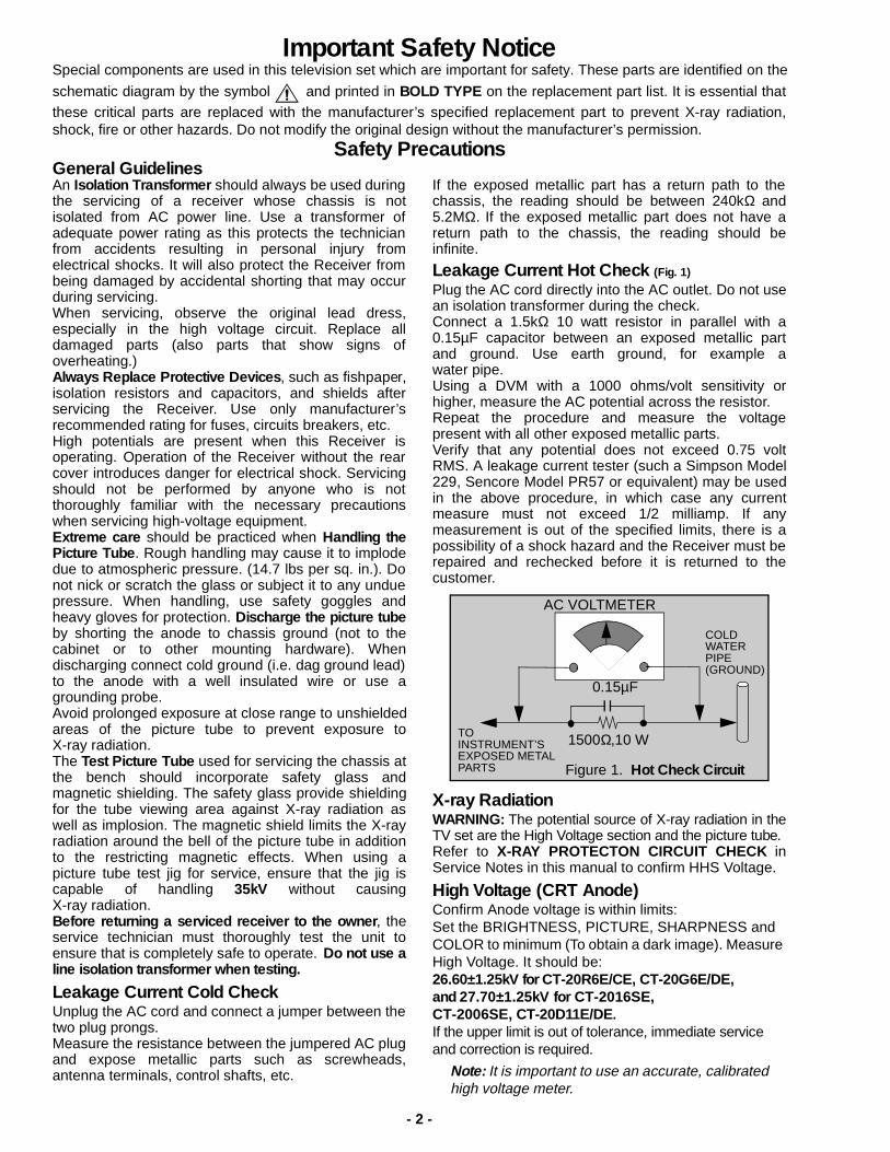
Leakage Current Hot Check (Fig. 1)
Plug the AC cord directly into the AC outlet. Do not usean isolation transformer during the check.Connect a 1.5kΩ 10 watt resistor in parallel with a0.15µF capacitor between an exposed metallic partand ground. Use earth ground, for example awater pipe.Using a DVM with a 1000 ohms/volt sensitivity orhigher, measure the AC potential across the resistor.Repeat the procedure and measure the voltagepresent with all other exposed metallic parts.Verify that any potential does not exceed 0.75 voltRMS. A leakage current tester (such a Simpson Model229, Sencore Model PR57 or equivalent) may be usedin the above procedure, in which case any currentmeasure must not exceed 1/2 milliamp. If anymeasurement is out of the specified limits, there is apossibility of a shock hazard and the Receiver must berepaired and rechecked before it is returned to thecustomer.
X-ray RadiationWARNING: The potential source of X-ray radiation in theTV set are the High Voltage section and the picture tube.Refer to X-RAY PROTECTON CIRCUIT CHECK inService Notes in this manual to confirm HHS Voltage.
High Voltage (CRT Anode)Confirm Anode voltage is within limits:Set the BRIGHTNESS, PICTURE, SHARPNESS and COLOR to minimum (To obtain a dark image). Measure High Voltage. It should be:26.60±1.25kV for CT-20R6E/CE, CT-20G6E/DE,and 27.70±1.25kV for CT-2016SE,CT-2006SE, CT-20D11E/DE.If the upper limit is out of tolerance, immediate service and correction is required.
Note: It is important to use an accurate, calibratedhigh voltage meter.
Leadless Chip Compon ent(surf ace mount)Chip components must be replaced with identical chipsdue to critical foil track spacing. There are no holes inthe board to mount standard transistors or diodes.Some chips capacitor or resistor board solder padsmay have holes through the board, however the holediameter limits standard resistor replacement to 1/8watt. Standard capacitor may also be limited for thesame reason. It is recommended that identicalcomponents be used.Chip resistor have a three digit numerical resistancecode - 1st and 2nd significant digits and a multiplier.Example: 162 = 1600 or 1.6kΩ resistor, 0 = 0Ω (jumper).Chip capacitors generally do not have the valueindicated on the capacitor. The color of the componentindicates the general range of the capacitance.Chip transistors are identified by a two letter code. Thefirst letter indicates the type and the second letter, thegrade of transistor.Chip diodes have a two letter identification code as perthe code chart and are a dual diode pack with eithercommon anode or common cathode. Check the partslist for correct diode number.
Component Removal1. Use solder wick to remove solder from component
end caps or terminal.2. Without pulling up, carefully twist the component
with tweezers to break the adhesive.3. Do not reuse removed leadless or chip
components since they are subject to stressfracture during removal.
Chip Component Installation1. Put a small amount of solder on the board
soldering pads.2. Hold the chip component against the soldering
pads with tweezers or with a miniature alligator clipand apply heat to the pad area with a 30 watt ironuntil solder flows. Do not apply heat for more than3 seconds.
How to Replace Flat-IC- Required Tools -
1. Cut the pins of the defective IC with the wire cutterspliers, and remove it completely away from theboard. If the IC is glued to the board, apply hot airto complete the removal. CAUTION- Do not pull ortwist the pliers, it may damage the soldering pads inthe board.
2. Using the Soldering Iron and the long nose pliers,remove the IC pins that still attached to the board.
3. Using the De-solder braid and the Soldering Iron,remove the solder from the board soldering pads.
4. Position the new Flat-IC in place (apply the pins ofthe Flat-IC to the soldering pads where the pinsneed to be soldered). Properly determine thepositions of the soldering pads and pins bycorrectly aligning the polarity symbol. Start aligningand soldering Pin No.1, then align and solder thepin in the apposite corner of the IC, this will help toalign the rest of the pins.
5. Solder all pins to the soldering pads using a finetipped soldering iron.
6. Check with a magnifier for solder bridge betweenthe pins or for dry joint between pins and solderingpads. To remove a solder bridge, use a de-solderbraid as shown in the figure below.
Note: These components are affixed with glue. Be careful not to break or damage any foil under thecomponent or at the pins of the ICs when removing. Usually applying heat to the component for a short timewhile twisting with tweezers will break the component loose.
c
b
e
Chip Components
TRANSISTOR CAPACITOR
RESISTORMH DIODE
SOLDERCAPS
SOLDERCAPS
1ST DIGIT 2ND DIGIT
MULTIPLIER=1600 = 1.6k
GRADE
TYPE
COMMON
ANODES
CATHODE
• Soldering iron • De-solder braids
• Sharp pliers (wire cutter and long nose)
• Magnifier
Flat-IC
SolderingIron
De-SolderBraid
SolderingIron
PolaritySymbol
SolderingIron
Solder
De-SolderBraid
SolderBridge
SolderingIron
- 5 -
Service Notes (Continued)IMPORTANT: To protect against possible damage tothe solid state devices due to arcing or staticdischarge, make certain that all ground wires and CTRDAG wire are securely connected.
CAUTION: The power supply circuit is above earthground and the chassis cannot be polarized. Use anisolation transformer when servicing the Receiver toavoid damage to the test equipment or to the chassis.Connect the test equipment to the proper ground () or( ) when servicing, or incorrect voltages will bemeasured.
WARNING: This Receiver has been designed to meetor exceed applicable safety and X-ray radiationprotection as specified by government agencies andindependent testing laboratories.
To maintain original product safety design standardsrelative to X-ray radiation and shock and fire hazard,
parts indicated with the symbol on the schematicmust be replaced with identical parts. Order parts fromthe manufacturer’s parts center using the partsnumbers shown in this service manual, or provide thechassis number and the part reference number.
For optimum performance and reliability, all other partsshould be replaced with components ofidentical specification.
X-RAY PROTECTION CIRCUIT CHECK
This test must be performed as final check before theReceiver is returned to the customer. If Voltage is out oftolerance, immediate service and correction is requiredto insure safe operation and to prevent the possibility ofpremature component failure.
Equipment needed to check the protection circuit:
1. Isolator transformer.2. High voltage meter.3. Short jumper.4. Diode connection jumper Use similar diode than D823, refer to parts list for part No., (Diode should support at least 150V.)
Procedure:1. Connect receiver to Isolator Transformer.2. Apply a monoscope pattern.3. In Service Mode. (Refer to Service Mode Section)
Select Register C0b.4. Measure TP5 (TPs port close to tuner). Compare
the measure of TP5 and set the data for C0baccording the following table
5. Exit Service Mode and turn Receiver OFF.6. Connect a jumper from TPD16 to TPD17.7. Connect the Diode jumper, cathode to TPD14
(COLD GND), anode to TPD15 (HOT GND). Note: Refer to Fig. 10 for Test Point Location.
8. Apply 75 V AC to the AC input of the Insulatortransformer.Turn receive ON.
9. Set PICTURE and BRIGTHNESS to minimum.10. Increase the AC voltage at the input of Insulator
transformer and confirm the HHS Voltage is33.1KV for CT-2016SE, CT-2006SE, CT-20D11E/DE and 32.4kV for CT-20R6E/CE, CT-20G6E/DE,at the point set starts to loose sync,
11. Reset picture controls to original levels.12. Turn the set OFF, and remove all jumpers and
connections from chassis.
TP 5 MEASURE (V)
DATA TO C0b (Hex)
0 ~ 0.93 00
0.93 ~ 0.97 01
0.97 ~ 1.01 02
1.01 ~ 1.05 03
1.05 ~ 1.09 04
1.09 ~ 1.13 05
1.13 ~ 1.17 06
1.17 ~ 1.21 07
- 6 -
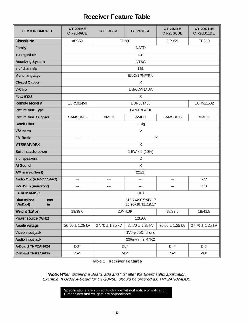
Receiver Feature Table
*Note: When ordering a Board, add and ” S” after the Board suffix application.Example, If Order A-Board for CT-20R6E, should be ordered as: TNP2AH024DBS.
Specifications are subject to change without notice or obligation.Dimensions and weights are approximate.
- 7 -
Location of Controls (Receiver)
Quick Reference Control Operation
Quick ReferenceControl Operation
Power Button - Press to turn ON or OFF.
Volume Buttons - Press to adjust Sound Level, or to adjust Audio Menus, VideoMenus, and select operating features when menus are displayed
Channel Buttons - Press to select programmed channels. Press to highlight desiredfeatures when menus are displayed. Also use to select Cable Converter box channelsafter programming Remote Control Infra-red codes (the TV/AUX/CABLE switch mustbe set in CABLE position).
Action Button - Press to display Main Menu and access On Screen feature andAdjustment Menus.
TV/Video Button - Press to select TV or Video Input.
1 2 4 53
POWER VOLUME CHANNEL ACTION TV/VIDEO
Remote ControlSensor
(Actual appearance may vary)
HPJ & A/V Jacks
Figure 2. Location of Controls (Receiver).
1
2
3
4
5
- 8 -
Location of Controls (Remote)
Figure 3. Location of Controls (Remote).
Power Button
Press to turn ON and OFF.
Mute Button
Press to mute sound.A second press resumes
sound.Press also to access and delete
Closed Caption display.
Volume Buttons
Press to adjust TV sound level.Use with Channel buttons to
navigate in menus.
Channel Buttons
Press to select channels.Use with volume buttons to
navigate in menus.
Action Button
Press to display Main Menu and access or exit On Screen
featuresand Adjustment Menus.
Keypad Buttons
Press desired channel numberto randomly access any
channel.
R-Tune (Rapid Tune) Button.
Press to switch to the previous channel.
Recall Button
Press to display Time, status of Sleep Timer, Channel,
Video mode and ChannelCaption (Station Identifier).
EUR501455CT-2016SE & CT-2006SE
EUR511502CT-20D11E & CT-20D11DE
CT-20G6E & CT-20G6DE
- 9 -
Location of Controls (Remote) Cont.
Figure 4. Location of Controls (Remote) .
Power Button
Press to turn ON and OFF.
Mute Button
Press to mute sound. A second press resumes sound. Press also to access
and delete Closed Caption display.
TV/Video Button
Press to select TV or Video input.
Volume Buttons
Press to adjust TV sound level. Use with Channel buttons to navigate in
menus.
Channel Buttons
Press to select channels. Use with volume buttons to navigate in menus.
Action Button
Press to display Main Menu and access or exit On Screen features and
Adjustment Menus.
Keypad Buttons
Press desired channel number to randomly access any channel.
R-Tune (Rapid Tune) Button.
Press to switch to the previous channel.
Recall Button
Press to display Time, status of Sleep Timer, Channel, Video mode and
Channel Caption (Station Identifier).
EUR501450CT-20R6E & CT-20R6CE
- 10 -
Disassembly for ServiceBack CoverRemove all the screws marked with an arrow( )from the back of the receiver. See Fig. 8.
Note: Screw configuration, type, and number ofscrews vary depending on the model of theReceiver serviced and the application; variousmodels are covered in this Manual. Use samehardware when reassembling the receiver.
• 2 screws at the top edge of the Receiver.• 2 screws at the lower corners of the Receiver.• 1 screw by the A/V jacks.• 1 screw by the Fly-back assembly.
A-Board - Main Chassis1. Pull carefully the tab in the chassis rail, at the left
side of the main chassis, this will release the railfrom the cabinet. See Fig 5.
2. Slide the chassis and rail completely out of theguide rails of the cabinet.
3. Stand the receiver on its edge. The underside ofthe board is completely accessible for componentreplacement.
Note: Some tie-wraps that secure the wiredressings may need to be unfastened for chassisremoval.
4. When reassembly, place the chassis rail on thecabinet, then place the main chassis, be sure is inthe rails at both sides, then push all the way to thefront.
Figure 5. Chassis Rail Detail
C-Board - CRT OutputPlugs into the socket on the CRT neck. To release the Focus wire, use a flat tool to releasethe tab in the socket, See Fig. 6 A, pull the wire-look up and remove the wire by pulling away thesocket B, To re-insert, close the wire-look bypushing until is secured with the tab, and insert thewire into the socket
Figure 6. Focus Wire Release
SpeakersSpeakers are secured to the cabinet’s front with 2screws in diagonal (opposite corners).
Keyboard Push Button AssemblyFastened to the inside of the cabinet front with 1 or2 screws, according to the model’s cabinet.
Disassembly for CRT Replacement1. Discharge the CRT as instructed in the Safety
Precautions (see page 2).2. Disconnect the yoke (DY) plug and degaussing coil
(DEG) plug from the main board.3. Unplug the CRT 2nd anode button.4. Remove the C-Board from the CRT base and
unplug the black wire (CRT dag ground) C10.5. Disconnect Speakers plug SP from the A-Board.6. Lift the Main Chassis (A-Board) completely out with
the CRT Board attached.
A B
- 11 -
CRT Replacement
1. Perform Disassembly for CRT Replacementprocedure.
2. Insure that the CRT H.V. Anode button isdischarged before handling the CRT. Read theSafety Precautions (see page 2) on handling thepicture tube.
3. Remove the components from the CRT neck andplace the cabinet face down on a soft pad.
4. Note the original order for the CRT mountinghardware.
5. Remove the CRT with the degaussing coil and thedag ground braid attached.
6. Note the original locations and mounting of thedegaussing coil and the dag ground assembly toinsure proper reinstallation on the replacementCRT.
To remove and remount the degaussing coil: Thedegaussing coil is held in place by 4 plastic tiesfastened to the CRT corner ears. To remove Coilcut the plastic ties. - 4 plastic ties are included in the Degaussing coilinstallation Kit (Refer to Parts List for correct PartNo)-. To re-mount, place the two smaller plastic ties inthe upper corners, holding the Coil, use the twobigger plastic ties to hold the Coil to the lowercorners. Confirm the Coil is tense and fasten to theCRT body.
To remove and remount the dag ground braid:a.Unhook the coil spring from the upper right
corner of the CRT.b.Release the braid loop from the lower left corner
of the CRT.
Figure 7. Deg Coil and DAG GND
7. Mount the dag ground braid on the replacementCRT as shown in Fig 7. Position the degaussingcoil with new ties. Dress coil as was on the originalCRT.
8. Replace the components on CRT neck andreinstall into cabinet. Verify that all ground wiresand circuit board plugs get connected.
- 12 -
Back Cover Disassembly
Figure 8. Back Cover Removal
• 2 Screw at the top edge• 1 Screw in each lower corner• 1 Screw by the A/V Jacks• 1 Screw by the Flyback Assembly.
IMPORTANTScrew number and configuration, A/V jacks and
connectors may vary according to the model.
- 13 -
Main Components Location
Figure 9. Rear View
Note: Audio and Video Inputs may vary according to the model.
ANODE(HIGH VOLTAGE)
CRT
by 4 Screws on Corners)(Secured to Cabinet DY
Deflection YokeCY
Convergence Yoke
DegaussingCoil
SpeakersSecured by2 Screws
A-BoardMain Chassis
Tuner S-VHSInput
A/V JACKS
Chassis Rail(some models)
C-BoardCRT Panel
Flyback Dag Ground
Yoke Wedge
IMPORTANTAfter servicing the receiver, remember to
dress the cables a shown above.
- 14 -
Main Components Location
Front A/V Jacks
IC451Vertical Out
IC003Remote Sensor
MPU/VCJ IC001 IC050
HALF TONECRT
SocketGROUND
Q351
Q352
Q353
JK3002IC002EEPROM
IC5525V REG
IC5519V REG
IC801VCO( )
Q501H. DRIVE
Q551H.OUT
RELAYRL801
RED OUT
GREEN OUT
BLUE OUT
TNR001TUNER
IC2301AUDIO AMP (R)
IC2302AUDIO AMP (L)
JK3001REAR A/V JACKS
F801FUSE( )
6.3A, 125/250V
D801( )RECT. BRIDGE.
- 15 -
Chassis Service Adjustment ProceduresAll service adjustments are factory preset and should not require adjustment unless controls and/or associatedcomponents are replaced.
Note: Connect the (-) lead of the voltmeter to the appropriate ground. Use IC801’s heat sink when the HOTground symbol ( ) is used. Otherwise, use COLD ground ( ) — Tuner shield, IC451’s heat sink or FA2.
COMPONENTS WITHIN DOT LINES ARE LOCATED AT THE OPOSITE SIDE OF BOARD.
130.0V B+ Voltage Confirmation1. Set the Bright and the Picture to Minimum by using
the Picture Menu.2. Connect the DVM between C825(+ side) and cold
ground ( ).3. Confirm that B+ voltage is 130.0V ± 2.5V. This
voltage supplies B+ to the Horizontal Output &Flyback circuits.
Source Voltage Chart120V AC line input. Set the Bright and the Picture toMinimum by using the Picture Menu. Use cold ground
( ) for the (-) lead of the DVM.
Adjust Picture Menu for normalized video adjustments.
High Voltage Check1. Select an active TV channel and confirm that
horizontal is in sync.2. Adjust Brightness and Picture using Picture Icon
menu so video just disappears.3. Confirm B+ 130V is within limit.4. Using a high voltage meter confirm that the High
Voltage is:
Figure 10. A-Board Main Components and Test Points
TPD8
SCREENFOCUS
IC552
IC551
TUNER
COLD ( )
HOT ( )
F801
D554
IC451A11
IC001
IC 801
C825
FA1
DATA
CLK
FA2
TPD9
D561
IC 003IC 002
CRTGND
IC2301
IC2302
IC050
TPD16
TPD15
TPD17
TPD14
TPE11
TPE10
LOCATION VOLTAGE
TPD8 26.0V ± 2V
TPD9 13.0V ± 2V
IC552 Pin3 5.0V ± 0.25V
IC551 Pin3 9.0V ± 0.25V
D554 Cathode 200V ± 15V
26.60kV±1.25kVCT-20R6E/CE,CT-20G6E/DE
(Models with Samsung CRT)
27.70kV±1.25kVCT-2016SE, CT-2006SE,
CT-20D11E/DE(Models with AMEC CRT)
- 16 -
Purity and Convergence ProcedureAdjustment is necessary only if the CRT or thedeflection yoke is replaced or if the setting wasdisturbed. The complete procedure consists of:1. Vertical Raster Shift Adjustment. (Only for Models
with Purity/Convergence Assembly with 4 Pairs ofRings) .
2. Initial static convergence.3. Setting the purity.4. Final static convergence.
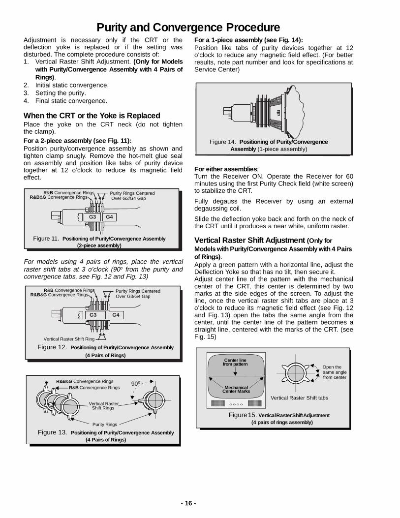
When the CRT or the Yoke is ReplacedPlace the yoke on the CRT neck (do not tightenthe clamp).For a 2-piece assembly (see Fig. 11):Position purity/convergence assembly as shown andtighten clamp snugly. Remove the hot-melt glue sealon assembly and position like tabs of purity devicetogether at 12 o’clock to reduce its magnetic fieldeffect.
For models using 4 pairs of rings, place the verticalraster shift tabs at 3 o’clock (90o from the purity andconvergence tabs, see Fig. 12 and Fig. 13)
For a 1-piece assembly (see Fig. 14):Position like tabs of purity devices together at 12o’clock to reduce any magnetic field effect. (For betterresults, note part number and look for specifications atService Center)
For either assemblies :Turn the Receiver ON. Operate the Receiver for 60minutes using the first Purity Check field (white screen)to stabilize the CRT.
Fully degauss the Receiver by using an externaldegaussing coil.
Slide the deflection yoke back and forth on the neck ofthe CRT until it produces a near white, uniform raster.
Vertical Raster Shift Adjustment (Only for Models with Purity/Convergence Assembly with 4 Pairs of Rings) .Apply a green pattern with a horizontal line, adjust theDeflection Yoke so that has no tilt, then secure it.Adjust center line of the pattern with the mechanicalcenter of the CRT, this center is determined by twomarks at the side edges of the screen. To adjust theline, once the vertical raster shift tabs are place at 3o’clock to reduce its magnetic field effect (see Fig. 12and Fig. 13) open the tabs the same angle from thecenter, until the center line of the pattern becomes astraight line, centered with the marks of the CRT. (seeFig. 15)
G3 G4
Purity Rings CenteredOver G3/G4 Gap
R&B Convergence RingsR&B&G Convergence Rings
Figure 11. Positioning of Purity/Convergence Assembly (2-piece assembly)
G3 G4
Purity Rings CenteredOver G3/G4 Gap
R&B Convergence RingsR&B&G Convergence Rings
Vertical Raster Shift Ring
Figure 12. Positioning of Purity/Convergence Assembly
(4 Pairs of Rings)
90o
Purity Rings
Vertical Raster
R&B Convergence RingsR&B&G Convergence Rings
Figure 13. Positioning of Purity/Convergence Assembly (4 Pairs of Rings)
Shift Rings
Figure 14. Positioning of Purity/Convergence Assembly (1-piece assembly)
Initial Center Static ConvergenceConnect a dot/cross hatch generator to the Receiverand tune in a signal. Observe misconvergence atcenter of the screen only.Adjust the R&B pole magnets; by separating tabs androtating to converge blue with red.Adjust the R&B&G pole magnets: by separating tabsand rotating to converge blue and red (magenta)with green.
Note: Precise convergence at this point isnot important.
Purity AdjustmentWhen the Receiver is in the Service Mode for makingelectronic adjustments, press the Recall button on theRemote Control to enter Purity Check. (See theService Adjustments Electronic Controls procedure).Operate the Receiver for 60 minutes using the firstPurity Check field (white screen) to stabilize the CRT.Fully degauss the Receiver by using an externaldegaussing coil.Press the Recall button on the Remote Control againuntil the Purity Check (green screen) appears.
For a 2-piece assembly (see Fig. 11):Loosen the deflection yoke clamp screw and move thedeflection yoke back as close to the purity magnetas possible.Adjust the Purity rings to set the vertical green rasterprecisely at the center of the screen (see Fig. 16).
Slowly move the deflection yoke forward until the bestoverall green screen is displayed.
For a 1-piece assembly (see Fig. 14):Slowly move the deflection yoke and purity ringsassembly toward the CRT board and adjust the purity
magnet rings to set vertical green raster at center ofscreen (see Fig. 16).Gradually move the deflection yoke & purity ringsforward and adjust for best overall green screen.
Continue from here for either assemblies:Tighten the deflection yoke clamp screw.Press the Recall button on the Remote Control againuntil the purity check (blue screen) and (red screen)appear and observe that good purity is obtained oneach respective field.Press the Recall button on the Remote Control againuntil Purity check (white screen) appears. Observe thescreen for uniform white. If purity has not beenachieved, repeat the above procedure.
Final Convergence Procedure (see Fig. 17through Fig. 19):
Note: Vertical size and focus adjustments mustbe completed prior to performing theconvergence adjustment. Connect a dot patterngenerator to the Receiver. The Brightness levelshould not be higher than necessary to obtain aclear pattern.
Converge the red and the blue dots at the center of thescreen by rotating the R&B pole Static ConvergenceMagnets.Align The converged red/blue dots with the green dotsat the center of the screen by rotating the R&B&G poleStatic Convergence Magnets. Melt wax with solderingiron to reseal the magnets.Slightly tilt vertically and horizontally (do not rotate) thedeflection yoke to obtain a good overall convergence.If convergence is not reached at the edges, insertpermalloy (see following section) from the DY cornersto achieve proper convergence. Recheck for purity andreadjust if necessary.After vertical adjustment of the yoke, insert wedge at 11o’clock position, then make the horizontaltilt adjustment.Secure the deflection yoke by inserting two sidewedges at 3 and 7 o’clock positions.Apply adhesive between tab (thin portion) of wedgeand CRT and place tape over the tab to secure tothe CRT.
Permalloy Convergence Corrector Strip (Part No. 0FMK014ZZ)This strip is used in some sets to match the yoke andCRT for optimum convergence. If the yoke or CRT isreplaced, the strip may not be required.First converge the set without the strip and observethe corners.
If correction is needed:1. Place strip between CRT and yoke, in quadrant
needing correction. Slowly move it around fordesired results.
2. Press adhesive tightly to the CRT and securewith tape.
NOTES:1. CRT warm up with white screen
(three guns activated) is neededto stabilize the shadow maskexpansion.
2. Initial center static convergence(roughly centers three gunbeams) is required in order toperform purity adjustment.
Figure 16. Green Raster Adjustment Green Raster
- 18 -
RG
B
As the yoke is tiltedvertically, the rastersproduced by the outsideguns rotate in oppositedirections.
Figure 17. Vertical Yoke Movement
R G B
Raster produced from one of theoutside electron beams
Raster from the other side electronbeam
Static convergence magnets are set forcenter convergence
As the yoke is tilted horizontally, oneraster gets larger while the other getssmaller
Figure 18. Horizontal Yoke Movement
11 o’clock Position
Double sided adhesive tape
3 o’clock Position
7 o’clock Position
ConvergesR/B with G
ConvergesR with B
Purity/ConvergenceAssembly Clamp
Purity Rings Adj. on Green Raster
Static Convergence Magnets
Yoke Positioning Wedges for Dynamic Convergence
Figure 19. Convergence Magnets and Wedges Location
Note: For models using 4 pairs ofrings assemblies see Fig. 12 for
- 19 -
Service Mode (Electronic Controls)This Receiver has electronic technology using the I²C Bus Concept. It performs as a control function and itreplaces many mechanical controls. Instead of adjusting mechanical controls individually, many of the controlfunctions are now performed by using “On Screen Display Menu”. (The Service Adjustment Mode .)
Note: It is suggested that the technician reads all the way through and understand the following procedure forEntering/Exiting the Service Adjustment Mode ; then proceed with the instructions working with the Receiver.When becoming familiar with the procedure, the Flow Chart for Serviceman Mode may be used as a quickguide.
Quick Entry to Service Mode:At times when minor adjustments need to be done to the electronic controls, the method of Entering the serviceMode without removal of the cabinet back is as follows using the Remote Control:
1. Select SET-UP icon and select CABLE mode.2. Select TIMER icon and set SLEEP time for 30 Min.3. Press ACTION button twice to exit menus.4. Tune to the Channel 124.5. Adjust VOLUME to minimum (0).
6. Press the VOL button (decrease) on Receiver . Red “CHK” appears in upper corner.
7. Press the Power Button on the Remote Control to select one of Service Adjustment Modes. 1) B= Service VCJ SUB-DATA adjustments. 2) C= Service VCJ CUT-OFF adjustments. 3) S= Service OPTIONS (PICTURE) adjustments. 4) M= Service MTS adjustments. 5) P= Service VCJ adjustments. 6) X= Service AFC adjustments 6) “CHK” = Normal operation of CHANNEL and VOLUME .
Exiting the Service Mode:Press the Action and the Power buttons on the Receiver simultaneously for at least 2 seconds. THE RECEIVER EXITS SERVICE MODE.The Receiver momentarily shuts off; then comes back on tuned to channel 3 with a preset level of sound.Any programmed channels, channels caption data and some others user defined settings will be erased.
To toggle between Aging and Service modes:While the “CHK” is displayed on the left top corner of the CRT, pressing the Action and the Volume Up buttonson the Receiver simultaneously will toggle between the modes. Red “CHK” for Service and yellow “CHK” forAging (Aging mode is used in the factory for quick operation).
An address Menu appears in the righthand corner of the screen
B 00 33 C 00 1 255
ba baNote: Only the applicablesettings for the Receiverserviced will be available (See ain Fig. 20).
Figure 20. Service Mode Menu Adjustments.
IMPORTANT NOTE: Always Exit the Service Mode
Following Adjustments.
- 20 -
IMPORTANTRegisters marked as FIXED in the following tables, are factory preset ,
service personnel should not change the default value.
Press the Power Button on the Remote Control to select the Service Adjustment.
For Adjustments:
Sub-Data Adjustment Adj. RangeDefault Level
B0 SUB-COLOR 0 ~ 127 33
B1 SUB-TINT 0 ~ 127 36
B2 SUB-BRIGHTNESS 0 ~ 255 127
B3 SUB-CONTRAST 0 ~ 127 20
B4 R-OFF SET FIXED 0
B5 Y NOISE REDUCTION FIXED 0
B6 Y NR LIMIT FIXED 0
Cut-Off Adjustment Adj. RangeDefault Level
C0 CUT-OFF R0 ~ 2551 ~ 255
0255
C1 CUT-OFF G0 ~ 2551 ~ 255
0255
C2 CUT-OFF B0 ~ 2551 ~ 255
0255
C3 DRIVE R 0 ~ 127 80
C4 DRIVE B 0 ~ 127 80
C5 DRIVE G 0 ~ 127 80
C6 VERTICAL SIZE 0 ~ 255 127
C7 NOT USED N/A N/A
C8 NOT USED N/A N/A
C9 HORIZONTAL CENTER 0 ~ 31 16
Ca BEAM LIMIT 0 ~ 1 1
Cb HHS 0 ~ 7 0
Cc OSD-SHIFT FIXED 88
Cd ACL-REF FIXED 74
1.Press Channel Up/Down on theRemote Control to select one ofthe available Service Adjustments(a in Fig. 20).
Note: Write Down the originalvalue set (b in Fig. 20) for eachaddress before modifyinganything. It is easy toerroneously adjust the wrongitem.
2.Press Volume Up/Down on theRemote Control to adjust thelevel of the selected ServiceAdjustment (b in Fig. 20).
Note: Some adjustments modesmay not be available in somemodels depending on availableoptions.
IMPORTANT NOTE:Always Exit the Service Mode
Following Adjustments.
To Item P00
CH
PW
To B Items
CH
- 24 -
To Check Purity:In Service mode (red “CHK” is displayed), place a jumper in AG connector, press the Recall Button on the RemoteControl to enter to the White purity field check, remove the jumper, press Recall again to get to Red, Green andBlue purity fields (If jumper is not removed for color fields, they will be displayed with higher luminosity),
In Aging mode (factory mode, yellow “CHK” is displayed), connect a jumper in AG connector, press the RecallButton on the Remote Control to enter the Purity Field Check Mode.
Press Recall again to select desired field.
NORMAL SCREEN
WHITE SCREEN
RED SCREEN
GRN. SCREEN
BLUE SCREEN
Figure 21. Purity Check Field Mode .
Helpful Hints
Entering Service Mode (Back-Open Method)1. While the Receiver is ON and operating in Normal Mode, momentarily
short test point FA1 (TP8) to Cold Ground ( ) FA2 (TP3) A-Board. The Receiver enters the Aging Mode . Yellow letters “CHK” appear in the upper left corner of the CRT. (The Volume Up/Down will adjust rapidly).2. Simultaneously press the Action and the Volume Up buttons on the
Receiver Control Panel. The Receiver enters the Service Mode. The letter in “CHK” turn red. (The Volume Up/Down will adjust normally). (All costumer controls are set to nominal level).
IMPORTANT NOTE:Always Exit the Service Mode
Following Adjustments.
- 25 -
Instructional Flow Chart for Service Mode
Adj. needed?
NORMAL MODE
Momentarily short FA1 to FA2 ().
Press Action + Volume Up Simultaneously (ON Receiver )
Adj. needed?
B ITEMSSUB-DATA
ADJUSTMENTS
Adj. needed?
WHITE SCREEN
(ON REMOTE)
(ON REMOTE)
RECALL
WHITE SCREEN
RED SCREEN
GRN. SCREEN
BLUE SCREEN
POWER
(ON REMOTE)
AGING MODE• Yellow “CHK” appears in upper left corner of screen.• Volume Up/Down operate rapidly.• Customer Controls are set to nominal level.
SERVICE MODE• “CHK” turns red.• Volume Up/Down operate normally.• Customer Controls are set to nominal level.
SUB-DATA ADJUSTMENTS.B ITEMS.
A
QUICK ENTRY TO SERVICE MODE• Select CABLE Mode.• Set SLEEP time for 30 Min.• Tune to Channel 124.• Adjust Volume to minimum.• Press VOL DOWN. On Receiver.
CHCH
EXIT
EXIT
Figure 22.Flow Chart for Serviceman Mode .
N
Y
N
Y
N
Y
B
IMPORTANT NOTE:Always Exit the Service Mode
Following Adjustments.
(ON REMOTE)
RECALL
POWER
(ON REMOTE)
USE VOL TO SET THE VALUE
ACTION & VOLUME to AGING ModeACTION & POWER to RESET TV
Jumper in AG connector
Jumper in AG connector
Remove jumper from AG
connector
- 26 -
Instructional Flow Chart for Serviceman Mode - Continued
Adj. needed?
CUT-OFF ADJUSTMENTS.C ITEMS.
A
EXIT
N
Y
MTS ADJUSTMENTS.M ITEMS.
Adj. needed?
N
Y
OPTIONS ADJUSTMENTS.S ITEMS.
ACFC ADJUSTMENTS.X ITEMS.
Adj. needed? BY
N
N
POWER
(ON REMOTE)
POWER
(ON REMOTE)
POWER
(ON REMOTE)
POWER
(ON REMOTE)
C ITEMSCUT-OFF
ADJUSTMENTS
(ON REMOTE)
CHCH
(ON REMOTE)
CHCH
S ITEMSOPTIONS (PICTURE)
(ON REMOTE)
CHCH
M ITEMSMTS CIRCUIT
ADJUSTMENTS
VCJ ADJUSTMENTS.P ITEMS.
(ON REMOTE)
CHCH
P ITEMSVCJ
(ON REMOTE)
CHCH
X ITEMSAFC ADJUSTMENTS
Figure 23. Flow Chart for Serviceman Mode .(Continued)
USE VOL TO SET THE VALUE
USE VOL TO SET THE VALUE
USE VOL TO SET THE VALUE
ACTION & VOLUME to AGING ModeACTION & POWER to RESET TV
- 27 -
Service Adjustments (Electronic Controls)Note: Is recommended to allow at 30 min. warmup at highest bright (using white screen) beforeperform any picture adjustment.
Sub-ContrastService DAC (B3)This adjustment is factory set. Do not adjust unlessrepairs are made to associated circuit, the CRT Boardor when the CRT is replaced.
Preparation:1. Apply a color bar signal pattern with 87.5%
modulation, 70% saturated color bar with a 100IRE white and 7.5 black.
Note: The pattern used in this procedure is an EIAcolor bar pattern with 87.5% modulation with 100 IREwhite and 7.5 black. Correlate the information in thisprocedure to the pattern used if another signal is used.
3. Connect the scope probe between TP35 (C-Board)and cold ground ( ).
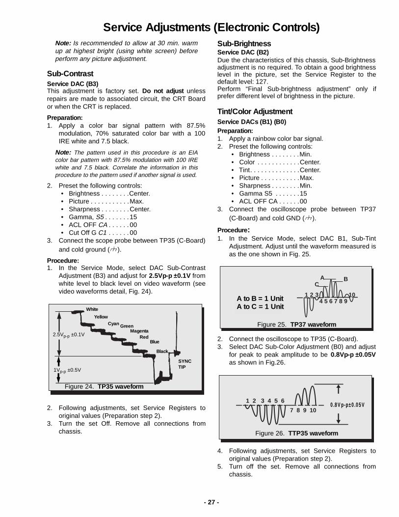
Procedure:1. In the Service Mode, select DAC Sub-Contrast
Adjustment (B3) and adjust for 2.5Vp-p ±0.1V fromwhite level to black level on video waveform (seevideo waveforms detail, Fig. 24).
2. Following adjustments, set Service Registers tooriginal values (Preparation step 2).
3. Turn the set Off. Remove all connections fromchassis.
Sub-BrightnessService DAC (B2)Due the characteristics of this chassis, Sub-Brightnessadjustment is no required. To obtain a good brightnesslevel in the picture, set the Service Register to thedefault level: 127. Perform “Final Sub-brightness adjustment” only ifprefer different level of brightness in the picture.
Tint/Color AdjustmentService DACs (B1) (B0)Preparation:1. Apply a rainbow color bar signal.2. Preset the following controls:
3. Confirm with Black-White pattern and a WhiteScreen the actual balance (Gray scale and whitelevel). If White Balance is required perform theProcedure steps as follow.
Procedure:
CUT-OFF Adjustment (Low Lights)1. Apply a Black-White pattern.2. Connect a jumper from Q452-Base to cold
ground ( ). (Or apply +2.5 V dc to TP1 and coldground ( )) to dis-habilitate the Neck Protectorcircuit.
3. Set Red Cut-Off (C0) and Blue Cut-Off (C2)registers to 00.
4. Press R-Tune in the remote control (to close thevertical circuit and get green horizontal line),