1147 Related Information Selection Guide Laser Displacement Magnetic Displacement Collimated Beam Digital Panel Controller Metal-sheet Double-feed Detection GD FIBER SENSORS LASER SENSORS PHOTOELECTRIC SENSORS MICRO PHOTOELECTRIC SENSORS AREA SENSORS LIGHT CURTAINS / SAFETY COMPONENTS PRESSURE / FLOW SENSORS INDUCTIVE PROXIMITY SENSORS PARTICULAR USE SENSORS SENSOR OPTIONS SIMPLE WIRE-SAVING UNITS WIRE-SAVING SYSTEMS MEASUREMENT SENSORS STATIC ELECTRICITY PREVENTION DEVICES LASER MARKERS PLC HUMAN MACHINE INTERFACES ENERGY CONSUMPTION VISUALIZATION COMPONENTS FA COMPONENTS MACHINE VISION SYSTEMS UV CURING SYSTEMS Metal-sheet Double-feed Detector GD SERIES From ultra-thin lead frames to iron sheets... Double feed detection of various metal sheets Double metal sheets detected The high-end GD sensing technology detects double feeds of any metal sheet 0.01 mm 0.0004 in, or more, thick. Easy sensitivity setting with actual samples Optimum sensitivity setting is easy by using the teaching function with actual samples. 1 Press the “0-ADJ. key” while no object exists between sensor heads. 2 Place one sheet between the sensor heads and press the “SET-1 key”. 3 Place two sheets between the sensor heads and press the “SET-2 key”. Three types of sensor heads for various objects VARIETIES Small object detection sensor head / GD-3 High precision sensor head / GD-10 Long sensing range sensor head / GD-20 This is an extremely small sensor head, only ø3.8 × 15 mm ø0.150 × 0.591 in, suitable for detecting small components. It is suitable for high precision detection of double feeds of lead frames or thin metal sheets. It achieves a long sensing range of 70 mm 2.756 in. Further, it employs a robust metal case with IP67 protection to withstand harsh environment. 15 mm 0.591 in ø3.8 mm ø0.150 in 7.1 mm 0.280 in 12 mm 0.472 in 32.2 mm 1.268 in Sensing range 70 mm 2.756 in ■ General terms and conditions ............. F-7 ■ General precautions....................... P.1501 Phone: 800.894.0412 - Fax: 888.723.4773 - Web: www.clrwtr.com - Email: [email protected]
Transcript
1147
Related Information
Selection GuideLaser
DisplacementMagnetic
DisplacementCollimated
BeamDigital Panel
ControllerMetal-sheet
Double-feed Detection
GD
FIBERSENSORS
LASERSENSORS
PHOTOELECTRICSENSORS
MICROPHOTOELECTRIC
SENSORS
AREASENSORS
LIGHT CURTAINS /SAFETY
COMPONENTSPRESSURE /
FLOWSENSORS
INDUCTIVEPROXIMITY
SENSORS
PARTICULARUSE SENSORS
SENSOROPTIONS
SIMPLEWIRE-SAVING
UNITS
WIRE-SAVING SYSTEMS
MEASUREMENTSENSORS
STATIC ELECTRICITYPREVENTION
DEVICES
LASERMARKERS
PLC
HUMAN MACHINE INTERFACES
ENERGY CONSUMPTION VISUALIZATION COMPONENTS
FA COMPONENTS
MACHINE VISION SYSTEMS
UV CURING SYSTEMS
Metal-sheet Double-feed Detector
GD SERIES
From ultra-thin lead frames to iron sheets...Double feed detection of various metal sheets
Double metal sheets detectedThe high-end GD sensing technology detects double feeds of anymetal sheet 0.01 mm 0.0004 in, or more, thick.
Easy sensitivity setting with actual samplesOptimum sensitivity setting is easy by using the teaching function with actual samples.
1 Press the “0-ADJ. key” while no object exists between sensor heads.
2 Place one sheet between the sensor heads and press the “SET-1 key”.
3 Place two sheets between the sensor heads and press the “SET-2 key”.
Three types of sensor heads for various objects
VARIETIES
Small object detection sensor head / GD-3 High precision sensor head / GD-10 Long sensing range sensor head / GD-20This is an extremely small sensor head, only ø3.8 × 15 mm ø0.150 × 0.591 in, suitable for detecting small components.
It is suitable for high precision detection of double feeds of lead frames or thin metal sheets.
It achieves a long sensing range of 70 mm 2.756 in. Further, it employs a robust metal case with IP67 protection to withstand harsh environment.
15 mm0.591 in
ø3.8 mmø0.150 in
7.1 mm0.280 in
12 mm0.472 in
32.2 mm1.268 in
Sensing range70 mm
2.756 in
General terms and conditions ............. F-7 General precautions .......................P.1501
Detecting overlap of washersGD-3 detects an overlap of small components such as washers.
Detecting double feeds of lead framesThe high precision sensor head GD-10 does not miss double feeds of lead frames even if they are very thin and highly perforated.
Detecting double feeds of sheet metalThe long sensing range sensor head GD-20 allows the object thickness to be as much as 10 mm 0.394 in. Hence, various objects can be detected.
GD-10GD-20
Tablet packagesGD-3
Detecting seam of hoop materialEven a minute difference in thickness can be detected.
Detecting double feeds of aluminum foilsGD-10 can detect double feeds of thin aluminum foils which are several tens of micrometer thick.
Detecting missing tablet package in boxGD-20 can check if each box contains a given number of aluminum tablet packages.Since GD-20 has a sensing range of up to 70 mm 2.756 in, thick boxes can pass through the sensor heads.
Seven LEDs indicate the sensing levelThe optimum sensing point can be confirmed at a glance as seven LEDs indicate the sensing level.
FUNCTIONS
Two-sheet level
One-sheet level
Sensing level indicators
Suitable for flexible manufacturing
Two-sheet threshold level shift functionThe two-sheet threshold level set by teaching can be shifted in nine steps to suit the detection conditions. This enables very stable detection.
In normal teaching, the two-sheetthreshold level is set at 5 (50 %).
Since sensitivities of eight channels can be stored, product changeover is smooth and easy.Select channel number by the “Channel shift key” on the operation panel or by using external channel select inputs.Further, since GD-C2 is equipped with RS-232C communication function, the sensitivity values can be stored in a personal computer, etc., and fed into the controller as per requirement.
GD-C2
Article A Article B Article C
RS-232C
1
2
3
IN-0
IN-1
IN-2 0V
Channeldisplay
Channelshift key
External channel select inputs
External initializationTeaching is possible by external devices, such as, PLC, etc. This enhances productivity by machine automation. R
Type Appearance Sensing range(between sensor heads) Detectable sheet thickness Model No. Applicable
controllers
Sm
all o
bjec
t det
ectio
n
10 mm 0.394 in
Standard sensing object size: 20 × 20 mm 0.787 × 0.787 in
GD-3 GD-C3
MaterialSetting distance 5 mm 0.197 in 10 mm 0.394 in
Iron (SPCC) 0.01 to 0.1 mm 0.0004 to 0.004 in 0.03 to 0.1 mm 0.001 to 0.004 inAluminum 0.015 to 1 mm 0.001 to 0.039 in 0.015 to 1 mm 0.001 to 0.039 inCopper 0.018 to 1 mm 0.001 to 0.039 in 0.018 to 0.3 mm 0.001 to 0.012 inBrass 0.03 to 1 mm 0.001 to 0.039 in 0.03 to 0.5 mm 0.001 to 0.020 inStainless steel (SUS304) 0.3 to 1 mm 0.012 to 0.039 in 0.3 to 1 mm 0.012 to 0.039 in
Hig
h pr
ecis
ion
30 mm 1.181 in
Standard sensing object size: 80 × 80 mm 3.150 × 3.150 in
GD-10GD-C1GD-C2GD-C3
Setting distance20 mm 0.787 in 30 mm 1.181 in
MaterialApplicablecontrollers
Iron(SPCC)
GD-C1/C2 0.07 to 1 mm 0.003 to 0.039 in 0.07 to 0.5 mm 0.003 to 0.020 in
GD-C3 0.01 to 0.3 mm 0.0004 to 0.012 in 0.01 to 0.1 mm 0.0004 to 0.004 in
AluminumGD-C1/C2 0.03 to 6 mm 0.001 to 0.236 in 0.03 to 2 mm 0.001 to 0.079 inGD-C3 0.015 to 1 mm 0.001 to 0.039 in 0.015 to 1 mm 0.001 to 0.039 in
CopperGD-C1/C2 0.03 to 6 mm 0.001 to 0.236 in 0.03 to 2 mm 0.001 to 0.079 inGD-C3 0.018 to 1 mm 0.001 to 0.039 in 0.018 to 1 mm 0.001 to 0.039 in
BrassGD-C1/C2 0.03 to 6 mm 0.001 to 0.236 in 0.03 to 2 mm 0.001 to 0.079 inGD-C3 0.01 to 1 mm 0.0004 to 0.039 in 0.01 to 1 mm 0.0004 to 0.039 in
Stainless steel(SUS304)
GD-C1/C2 0.1 to 6 mm 0.004 to 0.236 in 0.1 to 2 mm 0.004 to 0.079 inGD-C3 0.05 to 2 mm 0.002 to 0.079 in 0.05 to 1 mm 0.002 to 0.039 in
Long
sen
sing
rang
e
70 mm2.756 in
Standard sensing object size: 200 × 200 mm 7.874 × 7.874 in
GD-20 GD-C1GD-C2
MaterialSetting distance 35 mm 1.378 in 70 mm 2.756 in
Iron (SPCC) 0.07 to 10 mm 0.003 to 0.394 in 0.07 to 6 mm 0.003 to 0.236 inAluminum 0.03 to 10 mm 0.001 to 0.394 in 0.03 to 6 mm 0.001 to 0.236 inCopper 0.03 to 10 mm 0.001 to 0.394 in 0.03 to 6 mm 0.001 to 0.236 inBrass 0.03 to 10 mm 0.001 to 0.394 in 0.03 to 6 mm 0.001 to 0.236 inStainless steel (SUS304) 0.1 to 10 mm 0.004 to 0.394 in 0.1 to 6 mm 0.004 to 0.236 in
Note: Only the combinations between the sensor heads and the controllers described in the above table are allowed. Any other combination may damage the connected sensor heads.
10 m 32.808 ft cable length type and 20 m 65.617 ft cable length type10 m 32.808 ft cable length type and 20 m 65.617 ft cable length type for GD-20 are also available. (Standard: 3 m 9.843 ft)
Type Standard 10 m 32.808 ft cable length type 20 m 65.617 ft cable length type
Long sensingrange GD-20 GD-20-C10 GD-20-C20
Controllers
Type Appearance Model No. Output
Sta
ndar
d
GD-C1
NPN open-collector transistor
With
RS
-232
C
GD-C2
Sm
all o
bjec
t de
tect
ion
GD-C3
Make sure to use the sensor heads and the controller together in the above combinations.
HUMAN MACHINE INTERFACESENERGY CONSUMPTION VISUALIZATION COMPONENTS
FA COMPONENTS
MACHINE VISION SYSTEMS
UV CURING SYSTEMS
1150SPECIFICATIONS
Sensor headsType Small object detection High precision Long sensing range
Item Model No. GD-3 GD-10 GD-20Applicable controllers GD-C3 GD-C1, GD-C2, GD-C3 GD-C1, GD-C2Sensing range (between sensor heads) 10 mm 0.394 in or less 30 mm 1.181 in or less 70 mm 2.756 in or lessDetectable sheet thickness (Note 2) Standard sensing object size: 20 × 20 mm 0.787 × 0.787 in Standard sensing object size: 80 × 80 mm 3.150 × 3.150 in Standard sensing object size: 200 × 200 mm 7.874 × 7.874 in
Setting distance5 mm 0.197 in 10 mm 0.394 in 20 mm 0.787 in 30 mm 1.181 in 35 mm 1.378 in 70 mm 2.756 in
MaterialApplicable controllers
Iron (SPCC)
GD-C1/C2 – – 0.07 to 1 mm 0.003 to 0.039 in 0.07 to 0.5 mm 0.003 to 0.020 in 0.07 to 10 mm 0.003 to 0.394 in 0.07 to 6 mm 0.003 to 0.236 inGD-C3 0.01 to 0.1 mm 0.0004 to 0.004 in 0.03 to 0.1 mm 0.001 to 0.004 in 0.01 to 0.3 mm 0.0004 to 0.012 in 0.01 to 0.1 mm 0.0004 to 0.004 in – –
AluminumGD-C1/C2 – – 0.03 to 6 mm 0.001 to 0.236 in 0.03 to 2 mm 0.001 to 0.079 in 0.03 to 10 mm 0.001 to 0.394 in 0.03 to 6 mm 0.001 to 0.236 inGD-C3 0.015 to 1 mm 0.001 to 0.039 in 0.015 to 1 mm 0.001 to 0.039 in 0.015 to 1 mm 0.001 to 0.039 in 0.015 to 1 mm 0.001 to 0.039 in – –
CopperGD-C1/C2 – – 0.03 to 6 mm 0.001 to 0.236 in 0.03 to 2 mm 0.001 to 0.079 in 0.03 to 10 mm 0.001 to 0.394 in 0.03 to 6 mm 0.001 to 0.236 inGD-C3 0.018 to 1 mm 0.001 to 0.039 in 0.018 to 0.3 mm 0.001 to 0.012 in 0.018 to 1 mm 0.001 to 0.039 in 0.018 to 1 mm 0.001 to 0.039 in – –
BrassGD-C1/C2 – – 0.03 to 6 mm 0.001 to 0.236 in 0.03 to 2 mm 0.001 to 0.079 in 0.03 to 10 mm 0.001 to 0.394 in 0.03 to 6 mm 0.001 to 0.236 inGD-C3 0.03 to 1 mm 0.001 to 0.039 in 0.03 to 0.5 mm 0.001 to 0.020 in 0.01 to 1 mm 0.0004 to 0.039 in 0.01 to 1 mm 0.0004 to 0.039 in – –
Stainless steel(SUS304)
GD-C1/C2 – – 0.1 to 6 mm 0.004 to 0.236 in 0.1 to 2 mm 0.004 to 0.079 in 0.1 to 10 mm 0.004 to 0.394 in 0.1 to 6 mm 0.004 to 0.236 inGD-C3 0.3 to 1 mm 0.012 to 0.039 in 0.3 to 1 mm 0.012 to 0.039 in 0.05 to 2 mm 0.002 to 0.079 in 0.05 to 1 mm 0.002 to 0.039 in – –
Enviro
nmen
tal res
istance Protection IP67 (IEC) IP67 (IEC), IP67G
Ambient temperature –10 to +60 °C +14 to +140 °F, Storage: –25 to +70 °C –13 to +158 °FAmbient humidity 45 to 85 % RH, Storage: 35 to 95 % RHVibration resistance 10 to 55 Hz frequency, 1.5 mm 0.059 in amplitude in X, Y and Z directions for two hours eachShock resistance 1,000 m/s2 acceleration (100 G approx.) in X, Y and Z directions for three times each
Material Enclosure: Stainless steel (SUS 303), Sensing face: ABS Enclosure: Polyalylate Sensing face: Polyacetal, Main body: Stainless steel
Cable Sender: 0.3 mm2 single core shielded cable, 3 m 9.843 ft longReceiver: 0.1 mm2 2-core shielded cable, 3 m 9.843 ft long
Sender: 0.5 mm2 single core shielded cable, 3 m 9.843 ft longReceiver: 0.3 mm2 2-core shielded cable, 3 m 9.843 ft long
Cable extension Extension up to total 20 m 65.617 ft is possible with an equivalent shielded cable.Weight Net weight: 90 g approx. Net weight: 80 g approx. Net weight: 440 g approx.Accessory – Sensor head mounting bracket: 1 set for sender and receiver –
Notes: 1) Where measurement conditions have not been specified precisely, the conditions used were an ambient temperature of +20 °C +68 °F.2) The above detectable sheet thicknesses are typical data at the given sensing distance. The allowable thickness will differ from the range described in
the above table at other setting distances. Further, double feeds of aluminum foils can also be detected at distances shorter than the above. Please contact our office for details.
ControllersType Standard With RS-232C communication function Small object detection
Item Model No. GD-C1 GD-C2 GD-C3Supply voltage 12 to 24 V DC ±10 % Ripple P-P 10 % or lessCurrent consumption 12 V DC: 700 mA or less, 24 V DC: 400 mA or less
OutputOUT-1, OUT-2, ALM.Answer-back
NPN open-collector transistor• Maximum sink current: 100 mA• Applied voltage: 30 V DC or less (between output and 0 V)• Residual voltage: 1 V or less (at 100 mA sink current)
0.4 V or less (at 16 mA sink current)
Outpu
t Ope
ration OUT-1 OFF above the one-sheet threshold level
OUT-2 OFF above the two-sheet threshold levelA L M. OFF when an error occursAnswer-back (ANS. OUT) Refer to the time chart of the “Sensitivity setting of PRECAUTIONS FOR PROPER USE”
Short-circuit protection IncorporatedResponse time Automatically selected either 5 ms or less, or 30 ms or less, depending on the object 5 ms or lessSet level storage function Set values of eight channels storedSet level teaching function IncorporatedExternal setting function Incorporated
Indi
cato
rs
Power Green LED (lights up when the power is ON)Self-diagnosis (ALM.) Red LED (lights up during SET mode and when an error occurs during RUN mode)Sensing mode (SENSE) 2-color indicator (lights up green during normal sensing mode, but yellow during precise sensing mode)OUT-1 Green LED (lights up when OUT-1 is OFF, and blinks twice on completion of 0-ADJ. or SET-1 setting in SET mode)OUT-2 Red LED (lights up when OUT-2 is OFF, and blinks twice on completion of 0-ADJ. or SET-2 setting in SET mode)Sensing level Yellow LED × 1 and green LED × 6 (indicate the sensing level)
Timer function Approx. 50 ms fixed delay timer (switchable either effective or ineffective)
Envir
onme
ntal re
sistan
ce Ambient temperature –10 to +50 °C +14 to +122 °F (No dew condensation or icing allowed), Storage: –25 to +70 C° –13 to +158 °FAmbient humidity 45 to 85 % RH, Storage: 35 to 90 % RHVoltage withstandability 1,000 V AC for one min. between all supply terminals connected together and enclosureInsulation resistance 50 MΩ, or more, with 250 V DC megger between all supply terminals connected together and enclosureVibration resistance 10 to 55 Hz frequency, 0.75 mm amplitude in X, Y and Z directions for two hours eachShock resistance 300 m/s2 acceleration (30 G approx.) in X, Y and Z directions for three times each
Material Heat-resistant ABSWeight Net weight: 440 g approx.Accessory Insulation plate: 2 pcs.
Note: Where measurement conditions have not been specified precisely, the conditions used were an ambient temperature of +20 °C +68 °F.
* 1Note: Terminal 2 , 0 V of power supply, is isolated from 0 V of input / output circuitry for
noise immunity. However, if you expect to share the power supply with the output loads, connect terminals 2 and 6 , terminals 2 and 10 , or terminals 2 and 20 to make 0 V common.
I/O circuit diagram
+V
100 mA max.
12 to 24 V DC ±10 %
*1
OUT-1, OUT-2, ALM., Answer-back
IN-0, IN-1, IN-2, RUN / SET, SET-1, SET-2
+ –
D
Tr ZD
Sen
sor c
ircui
t
Output
0 V (Note)
Input
Internal circuit Users’ circuit
Load 0 V (Note)
30 V DC or less
+ –
Note: 0 V of power supply is isolated from 0 V of input / output circuitry. To share the power supply with a load, both the 0 V terminals should be short-circuited.
HUMAN MACHINE INTERFACESENERGY CONSUMPTION VISUALIZATION COMPONENTS
FA COMPONENTS
MACHINE VISION SYSTEMS
UV CURING SYSTEMS
1152
Normal sensing mode: The GD series goes into this mode when the number of objects (e.g., large metal sheets) is distinguished with relative ease.
PRECAUTIONS FOR PROPER USE Refer to p.1501 for general precautions.
Mounting of controller
<On DIN rail>
1 With the stopper pressed in the direction of the arrow (it locks), fit the front portion of the mounting section of the amplifier on the 35 mm 1.378 in width DIN rail.
2 Press and fit the rear portion of the mounting section on the 35 mm 1.378 in width DIN rail.
* To remove, insert a “minus”screwdriver into the stopperand pull out.
<On board with screws>
• Use two M4 pan headscrews 10 mm 0.394 in, ormore, long. The tighteningtorque should be 1.2 N·mor less.
Stopper
Stopper
35 mm 1.378 inwidth DIN rail
“Minus” screwdriver1
2
Two M4 pan head screws 10 mm 0.394 in, or more, long
Nut Purchaseseparately.
Purchaseseparately.
( )
( )
Placing of sensor heads
Mounting
• Make the sender and receiver face each other and aligntheir sensing center line.
• Keep a distance from any magnet or a device generatingmagnetic field. It may degrade the detectability.
• Surrounding metal influences the detectability. Pleasecontact our office for more details.
• If more than one set of sensor heads are closelymounted, detectability may be affected. Please contactour office for more details.
<GD-3>
Mounting with set screwSet screw(M3 or less) 4 mm 0.157 in or more
2 mm 0.079 in or more
• Use a set screw (M3 or less), and the tightening torqueshould be 0.12 N·m or less.
<GD-10>
Fixing at one point Fixing at two pointsM3 (length 12 mm 0.472 in)pan head screw(Accessory for GD-10)
Anti-sliprubber washer(Accessory for GD-10)
If mounting usingnut and washersAccessoriesfor GD-10
M3 × 0.5 mm 0.020 intapped hole, 10 mm 0.394 inor more deep, or ø3.4 mmø0.134 in thru-hole
( )ø2.5 mm ø0.098 in hole, 3 mm 0.118 inor more deep
M3 × 0.5 mm 0.020 intapped hole, 10 mm 0.394 inor more deep, or ø3.4 mmø0.134 in thru-hole
Mounting bracket(Accessory for GD-10)
If mounting usingnut and washersAccessoriesfor GD-10
16 mm0.630 in
M3 (length 12 mm 0.472 in)pan head screw(Accessory for GD-10)
( )M8 screwPurchaseseparately.
M8 mounting hole, 6 mm 0.236 in deep
( )
• The tightening torque should be 0.5N·m or less.
• To mount the sensor head with anut, the thru-hole should be ø3.4mm ø0.134 in.
• The tighteningtorque should be11.2 N·m or less.
<GD-20>
Mounting sensor heads
• Never use this product as a sensing devicefor personnel protection.
• In case of using sensing devices forpersonnel protection, use products whichmeet laws and standards, such as OSHA,ANSI or IEC etc., for personnel protectionapplicable in each region or country.
• Make sure to use the sensor heads andcontrollers in the specified combinations. Ifthey are used in any other combination, thesensor heads may get damaged.
The mounting board must be 2.3 mm 0.091 in, or less, thick.
Sensing mode• The GD series has two sensing modes, one is the normal
sensing mode and the other is the precise sensing mode.They are automatically selected by the characteristics ofthe object.
Iron etc.
Lead frame etc.
• The sensing mode indicator lights up green during thenormal sensing mode, but lights up yellow during theprecise sensing mode.
Precise sensing mode: The GD series goes into this mode when the number of objects (e.g., lead frames) is difficult to distinguish. In this mode, the sensitivity difference is so minute between two sensing levels that vibration and temperature changes must be carefully managed.
Distance from nearby metals• As metals near the sensor head may affect the sensing
performance, pay attention to the following points.
Influence of nearby metal
Transmission specifications
• The sensor head must be separated from nearby metalby a minimum distance as specified in the table below.
• Baud rate: Selectable from 300, 600, 1,200, 2,400, 4,800,9,600, 19,200, or 31,250 bits/sec.
• Format: Data bits ... 7 bits or 8 bitsParity check ........... None or Enable, Even or Odd Stop bits ................. 1 bit or 2 bits Terminal code ........ CR or ETX
Interference prevention
RS-232C DATA TRANSMISSION (GD-C2 only)
• When two or more sensor heads are mounted in parallel,keep a minimum separation distance as specified belowto avoid interference.
• GD-C2 can feed in the set level data into a PC or PLCmemory using RS-232C serial communication andretrieve it whenever required.In this case, the taught data should be stored in theprescribed channel.
• The GD series constantly runs self-diagnosis, outputsthe result with self-diagnosis output, and lights the self-diagnosis indicator. In addition, error content is shown onthe channel display using error codes.
Refer to p.1501 for general precautions.
In case the sender and another sensor’s receiver are placed adjacently
C
Sender Receiver
Receiver Sender
Setting distance (Note)Model No.
5 mm0.197 in
10 mm0.394 in
20 (35) mm0.787 (1.378) in
30 (70) mm1.181 (2.756) in
GD-3 60 mm 2.362 in 80 mm 3.150 in – –
GD-10 160 mm 6.299 in 220 mm 8.661 in
GD-20 370 mm 14.567 in 630 mm 24.803 in
Dimension C
Note: The value in the brackets is for GD-20.
Setting distance (Note)Model No.
5 mm0.197 in
10 mm0.394 in
20 (35) mm0.787 (1.378) in
30 (70) mm1.181 (2.756) in
GD-3 30 mm 1.181 in 50 mm 1.969 in – –
GD-10 200 mm 7.874 in 250 mm 9.843 in
GD-20 450 mm 17.717 in 700 mm 27.559 in
Dimension D
In case the respective senders and receivers are placed adjacently
D
Sender Receiver
Sender Receiver
Note: The value in the brackets is for GD-20.
Others
• Do not operate the sensor for a few seconds immediately after supplying power because of transient conditionsincluding self-diagnosis time.
• Make sure to check the ability of the sensor to detectthe number of sheets of your actual objects before use.If real objects differ from teaching samples in size orin characteristics, or the detecting condition deviates,an error may occur. Please note that magnetic metalsor metals with low magnetic permeability such as steelespecially have a strong tendency.
• In situations when magnets are in close proximity suchas during electromagnet conveyance, this causesmalfunctions due to electromagnetic disorder.
• When conducting minute detections, favorable sensingconditions are obtained only after having elapsed 60 min.after the initial introduction of the power supply.
Setting distanceModel No.
5 mm0.197 in
10 mm0.394 in
30 mm1.181 in
70 mm2.756 in
GD-3 15 mm 0.591 in
20 mm 0.787 in
– –
GD-10 100 mm 3.937 in –
GD-20 100 mm 3.937 in
Dimension A (in case of iron)
Embedding in metal
GD-10GD-3
Setting distanceModel No.
5 mm0.197 in
10 mm0.394 in
30 mm1.181 in
70 mm2.756 in
GD-3 ø15 mm ø0.591 in
ø20 mm ø0.787 in
– –
GD-10 ø100 mm ø3.937 in –
GD-20 ø300 mm ø11.811 in
Dimension B (in case of iron)
• The sensing performance may be affected if the sensoris completely embedded in a metal. Keep a minimumclearance between the sensor head and the metal asspecified in the table below.
Sensitivity setting
Teaching by external input• The teaching can also be performed by external input
signals.
GD-20
Time chart
RUN / SET select input
Answer-back output (ANS. OUT)
Answer-back output (ANS. OUT)
SET-1 input
SET-2 input
RUN High Low
50 ms or more High Low
High
High Low
Low
1 ms or less
1 ms or less
50 ms or more 50 ms or more
Teaching successful
High Teaching not successful
Low
50 ms or more SET
CPU process- ing time (a few seconds)
CPU process- ing time (a few seconds) Teaching successful
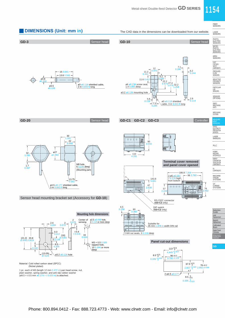
1 pc. each of M3 (length 12 mm 0.472 in) pan head screw, nut, plain washer, spring washer, and anti-slip rubber washer (ø9.5 × t 0.5 mm ø0.374 × t 0.020 in) is attached.


![completo - carlosluisribeiro.files.wordpress.com · ,qwurgxomr dr (vwxgr gd &) &rqfhlwr d 0dwhuldo 1~fohr 0dwpuldv hvvhqfldlv gd &) l 2ujdql]domr gr (vwdgr ll $txlvlomr h[huftflr](https://static.documents.pub/doc/80x56/5bf059ef09d3f22e178b6925/completo-qwurgxomr-dr-vwxgr-gd-rqfhlwr-d-0dwhuldo-1fohr-0dwpuldv-hvvhqfldlv.jpg)


![M =1vmunoz/homepage/cursos/mecanica1/... · gd k[`ba] F~ j z {k f ... l gd k[`ba] ` h ...](https://static.documents.pub/doc/80x56/5bfb36e809d3f2b5178c08e5/m-1-vmunozhomepagecursosmecanica1-gd-kba-f-j-z-k-f-l-gd-kba.jpg)


