Page 1
Panasonic Industrial Company Components GroupLine Card Catalog Summer 2008
Electrolytic Capacitors, Resistors, Film Capacitors, InductorsCeramic Capacitors, Varistors, Switches, RF Modules, DC-DC Converters
Page 3
How to identify a product familyPart NumberDesignations 4
Aluminum Electrolytic, Specialty Polymer, Electric Double Layer, Large Can Electrolytic Capacitors 6
Thick Film Chip, Low Resistance Thick fi lm Chip, Ultra Low Value Chip, High Power/Wide Terminal, Thin Film Chip, Linear Thermistors, Chip Attenuators,Chip Resistor Array, Chip R-Network, Chip RC-Netowrk, ESD Suppressors
Resistors 8
Stacked Metallized, Metallized Film/Foil, Metallized Film,Interference Suppressors, AC Use
Film Capacitors 10
High Frequency, General Use, High Current Inductors 12
Large Capacitance, Standard Capacitance, Low Profi le,Reverse Geometery Wide Terminations, Mid-Range Voltages, High Voltage,
Microwave, Array, Interference SuppressionCeramic Capacitors 14
Surface Mount, Leaded, Low Capacitance, Ultra Low Capacitance,High Capacitance, 2 Array, 4 Array, 2 Varistors 2 Capacitors Per Array
Varistors & Thermistors 16
Surface Mount, Leaded, Detector, Encoder, Faders for Audio Mixers Electromechanical 18
ISM, Bluetooth, nanoLOC, Mesh Networking, Z-Wave Wireless Modules 20
DC-DC Converters for AC Applications DC-DC Converters 22
Table of Contents
Panasonic Components are RoHS Compliant.For more information visit: http://www.panasonic.com/industrial/components/utilities/rohsfaqs.htm
Design and specifications are subject to change without notice. Please review technical specifications before purchase.For any safety concerns regarding these products, please contact us immediately for technical consultation.
For a part number cross reference please visit our website and click on Quick Cross Reference.http://www.panasonic.com/industrial/components/
Page 4
4
Component Part Number DesignationsA
BC
DE
FG
HJ
KL
M
EA
Sp
eake
r S
yste
ms
Sp
eake
r K
its
EC
Alu
min
um
Ele
ctro
lytic
C
aps.
(rad
ial
lead
)
Cer
amic
Dis
c C
ap.
Hi-
Q M
LCC
Alu
min
um
Ele
ctro
lytic
Cap
.P
last
ic F
ilm C
ap.
MLC
CC
eram
ic D
isc
Cap
(cla
ss 2
)
EE
Alu
min
um
Ele
ctro
lytic
C
aps.
(rad
ial
lead
)
Ele
ctric
Dou
ble
La
yer
Cap
.“G
old
Cap
”
SM
T A
L Ly
tic
(lead
free
)
Pol
ymer
Alu
min
um
Ele
ctro
lytic
C
apac
itors
EF
Pie
zoel
ectr
ic
Sp
eake
rs
Cer
amic
Filt
ers
Cer
amic
Filt
ers
Aco
usto
-Op
tic
Dev
ices
Saw
Dev
ices
EH
DC
DC
Con
vert
er
EK EL
LC F
ilter
s, D
uple
xers
, C
hoke
Coi
lsC
hoke
Coi
lsP
eaki
ng C
oils
Line
Filt
ers
Line
arity
Coi
lsC
hip
Ind
ucto
rsC
oil T
ype
EM
I Fi
lters
SM
D C
hoke
C
oils
EM EN
Up
/Dow
n C
onve
rter
s (C
ATV
)R
F M
odul
ator
sM
odul
esR
F Fr
ont
end
S
yste
m U
nits
VIF
Uni
ts
EO
Asp
heric
al
Gla
ss L
ens
EQ
Varia
ble
Ind
ucto
rsVa
riab
le In
duc
tors
ER
Met
al F
ilm C
hip
R
esis
tors
Circ
uit
Pro
tect
or;
Mic
ro C
hip
Fus
eC
arb
on F
ilm
Res
onat
ors
Wire
wou
nd
Res
isto
rsM
etal
(oxi
de)
Film
R
esis
tors
Thic
k Fi
lm C
hip
R
esis
tors
ES
Pus
h S
igna
l Sw
itche
sS
lide
Sw
itche
sP
ush
& D
etec
tor
Sw
itche
s
ET
Hi V
olta
ge
Tran
sfor
mer
sIn
put
/Out
put
Tr
ansf
orm
ers
Tran
sfor
mer
s:
Chi
p, p
ulse
; C
urre
nt; C
omm
on
Mod
e C
hoke
EU
Coi
n &
Bill
Va
lidat
ing
Uni
tsH
igh-
Volta
ge
Pow
er S
upp
lies
EV
Slid
e P
oten
tiom
eter
s;
Pos
ition
S
enso
rs
Slid
e P
oten
tiom
eter
sR
otar
y P
ots.
Enc
oder
sR
otar
y P
ots.
Rot
ary
Pot
s.C
erm
et T
rimm
er
Pot
s.
EW
Slid
e P
oten
tiom
eter
sE
ncod
ers,
Rot
ary
Pot
s.
EX
Chi
p R
esis
tor
Net
wor
ks, R
esis
tor
Arr
ay, C
hip
Att
n, R
C
Filte
r
Bea
d C
ores
; Chi
p
Bea
d C
ores
, Chi
p
Bea
d A
rray
s, E
MI
Filte
rs
Cap
acito
r N
etw
orks
EY
Gra
phi
te S
heet
Asp
heric
al
Gla
ss L
ense
s
EZ
Net
wor
ks: C
hip
C
ap.,
Chi
p R
D;
Chi
p 3
-ter
m
Cap
.
Mul
tilay
er V
aris
tor
Mag
neto
-Res
istiv
e E
lem
ent
Page 5
Electronic Components Group
5
Ele
ctro
lytic
C
apac
itors
Ind
ucto
rs,
Res
isto
rs, S
AW
D
evic
es, L
ense
s
Key
boa
rds,
R
emot
es, A
nten
na
Sw
itche
s,
Pot
entio
met
ers,
E
ncod
ers
Film
Cap
acito
rs,
MLC
C, Z
NR
, R
eson
ator
sH
igh
Freq
uenc
yP
ower
Sup
plie
s,
ALI
VH
, PW
B, A
udio
RF
Mod
ules
201-
392-
4955
201-
271-
3173
949-
462-
1809
201-
392-
6104
201-
392-
6920
201-
392-
4864
201-
392-
4864
201-
392-
4864
NO
PQ
RS
TU
VW
XY
Z
EA
Sp
eake
rs
EC
Alu
min
um
Ele
ctro
lytic
C
apac
itor
(Sna
p-i
n)
Pla
stic
Film
Cap
.P
last
ic F
ilm
Cap
.C
eram
ic
Trim
mer
Cap
.C
eram
ic
Trim
mer
Cap
.P
last
ic F
ilm C
ap.
Rev
erse
G
eom
eter
y M
LCC
EE
Alu
min
um
Ele
ctro
lytic
Cap
. (s
nap
-in
term
inal
)
Alu
min
um
Ele
ctro
lytic
Cap
. (R
adia
l Lea
d)
Alu
min
um
Ele
ctro
lytic
C
ap. (
SM
T)
EF
Cer
amic
R
eson
ator
sS
AW
Dup
lexe
rsP
iezo
elec
tric
R
ecei
vers
SA
W
Res
onat
ors
EH
Hyb
rid IC
s M
odul
e
EK
ALI
VH
EL
Volta
ge S
tep
-Up
C
oils
L-R
Filt
er
(Ind
ucto
r)
EM
Touc
h P
anel
s,
Key
less
Ent
ry
Sys
tem
s
EN
Fib
er O
ptic
C
omp
onen
tsE
lect
roni
c Tu
ners
RF
Mod
ules
EQ
Varia
ble
Ind
ucto
rsVa
riab
le
Ind
ucto
rs
ER
Pre
cisi
on
Met
al F
ilm
Res
isto
rs
Met
al F
ilm
Res
isto
rs
Met
al (O
xid
e)
Film
Fus
e R
esis
tors
Ther
mal
ly
Sen
sitiv
e R
esis
tors
NTC
Ter
mis
tors
Wire
wou
nd
Res
isto
rs w
/ Th
erm
al C
utof
fs
Wire
wou
nd
Res
isto
rsM
etal
Film
R
esis
tors
ZN
R T
rans
ient
S
urge
Ab
sorb
ers
ES
Pan
el S
witc
hes
Pan
el S
witc
hes
ET
Pow
er
Tran
sfor
mer
sP
ower
Cho
ke
Coi
lsS
witc
hing
Tr
ansf
orm
ers
Pow
er S
upp
ly
Uni
tsP
ower
Sup
ply
un
itsP
ower
Sup
ply
U
nits
EU
PTC
The
rmis
tors
; C
eram
isto
rR
emot
e C
ontr
ol
units
EV
Trim
mer
s:
Car
bon
C
hip
; 6m
m
Car
bon
Ligh
t To
uch
Sw
itche
sE
ncod
ers,
Lig
ht
Touc
h S
witc
hes
Rot
ary
Pot
s.P
ositi
on S
enso
rs,
Rot
ary
Pot
s.
EW
Ant
enna
Sen
sors
: D
isp
lace
men
t,
Rot
atio
n, A
ngul
ar
Rat
e
Rot
ary
Pot
s.
EY
Ther
mal
Cut
-offs
(T
CO
)
Tech
nic
al S
up
po
rt
Page 6
6
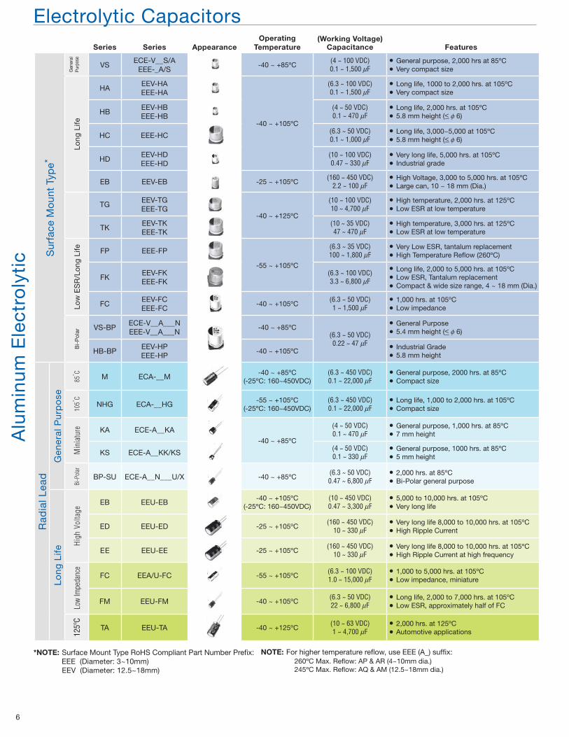
Series Series AppearanceOperating
Temperature(Working Voltage)
Capacitance Features
Alu
min
um E
lect
roly
tic S
urfa
ce M
oun
t Ty
pe*
Gen
eral
P
urpo
se
VSECE-V__S/A
EEE-_A/S-40 ~ +85ºC
(4 ~ 100 VDC)0.1 ~ 1,500 uF
]
]
General purpose, 2,000 hrs at 85ºCVery compact size
Long
Life
HAEEV-HAEEE-HA
-40 ~ +105ºC
(6.3 ~ 100 VDC)0.1 ~ 1,500 uF
]
]
Long life, 1000 to 2,000 hrs. at 105ºCVery compact size
HBEEV-HBEEE-HB
(4 ~ 50 VDC)0.1 ~ 470 uF
]
]
Long life, 2,000 hrs. at 105ºC5.8 mm height (< b 6)
HC EEE-HC(6.3 ~ 50 VDC)0.1 ~ 1,000 uF
]
]
Long life, 3,000~5,000 at 105ºC5.8 mm height (< b 6)
HDEEV-HDEEE-HD
(10 ~ 100 VDC)0.47 ~ 330 uF
]
]
Very long life, 5,000 hrs. at 105ºCIndustrial grade
EB EEV-EB -25 ~ +105ºC(160 ~ 450 VDC)
2.2 ~ 100 uF]
]
High Voltage, 3,000 to 5,000 hrs. at 105ºCLarge can, 10 ~ 18 mm (Dia.)
TGEEV-TGEEE-TG
-40 ~ +125ºC
(10 ~ 100 VDC)10 ~ 4,700 uF
]
]
High temperature, 2,000 hrs. at 125ºCLow ESR at low temperature
TKEEV-TKEEE-TK
(10 ~ 35 VDC)47 ~ 470 uF
]
]
High temperature, 3,000 hrs. at 125ºCLow ESR at low temperature
Low
ES
R/L
ong
Life FP EEE-FP
-55 ~ +105ºC
(6.3 ~ 35 VDC)100 ~ 1,800 uF
]
]
Very Low ESR, tantalum replacementHigh Temperature Reflow (260ºC)
FKEEV-FKEEE-FK
(6.3 ~ 100 VDC)3.3 ~ 6,800 uF
]
]
]
Long life, 2,000 to 5,000 hrs. at 105ºCLow ESR, Tantalum replacementCompact & wide size range, 4 ~ 18 mm (Dia.)
FCEEV-FCEEE-FC
-40 ~ +105ºC(6.3 ~ 50 VDC)1 ~ 1,500 uF
]
]
1,000 hrs. at 105ºCLow impedance
Bi-
Po
lar VS-BP
ECE-V__A___NEEE-V__A___N
-40 ~ +85ºC(6.3 ~ 50 VDC)0.22 ~ 47 uF
]
]
General Purpose5.4 mm height (< b 6)
HB-BPEEV-HPEEE-HP
-40 ~ +105ºC]
]
Industrial Grade5.8 mm height
Rad
ial L
ead
Gen
eral
Pur
po
se
85dC
M ECA-__M-40 ~ +85ºC
(-25ºC: 160~450VDC)(6.3 ~ 450 VDC)0.1 ~ 22,000 uF
]
]
General purpose, 2000 hrs. at 85ºCCompact size
105d
C
NHG ECA-__HG-55 ~ +105ºC
(-25ºC: 160~450VDC)(6.3 ~ 450 VDC)0.1 ~ 22,000 uF
]
]
Long life, 1,000 to 2,000 hrs. at 105ºCCompact size
Min
iatu
re KA ECE-A__KA-40 ~ +85ºC
(4 ~ 50 VDC)0.1 ~ 470 uF
]
]
General purpose, 1,000 hrs. at 85ºC7 mm height
KS ECE-A__KK/KS(4 ~ 50 VDC)0.1 ~ 330 uF
]
]
General purpose, 1000 hrs. at 85ºC5 mm height
Bi-P
olar
BP-SU ECE-A__N___U/X -40 ~ +85ºC(6.3 ~ 50 VDC)0.47 ~ 6,800 uF
]
]
2,000 hrs. at 85ºCBi-Polar general purpose
Long
Life
High
Vol
tage
EB EEU-EB-40 ~ +105ºC
(-25ºC: 160~450VDC)(10 ~ 450 VDC)0.47 ~ 3,300 uF
]
]
5,000 to 10,000 hrs. at 105ºCVery long life
ED EEU-ED -25 ~ +105ºC(160 ~ 450 VDC)
10 ~ 330 uF]
]
Very long life 8,000 to 10,000 hrs. at 105ºCHigh Ripple Current
EE EEU-EE -25 ~ +105ºC(160 ~ 450 VDC)
10 ~ 330 uF]
]
Very long life 8,000 to 10,000 hrs. at 105ºCHigh Ripple Current at high frequency
Low
Impe
danc
e
FC EEA/U-FC -55 ~ +105ºC(6.3 ~ 100 VDC)1.0 ~ 15,000 uF
]
]
1,000 to 5,000 hrs. at 105ºCLow impedance, miniature
FM EEU-FM -40 ~ +105ºC(6.3 ~ 50 VDC)22 ~ 6,800 uF
]
]
Long life, 2,000 to 7,000 hrs. at 105ºCLow ESR, approximately half of FC
125º
C
TA EEU-TA -40 ~ +125ºC(10 ~ 63 VDC)1 ~ 4,700 uF
]
]
2,000 hrs. at 125ºCAutomotive applications
Electrolytic Capacitors
*NOTE: Surface Mount Type RoHS Compliant Part Number Prefix: EEE (Diameter: 3~10mm) EEV (Diameter: 12.5~18mm)
NOTE: For higher temperature reflow, use EEE (A_) suffix: 260ºC Max. Reflow: AP & AR (4~10mm dia.) 245ºC Max. Reflow: AQ & AM (12.5~18mm dia.)
_
_
_
Page 7
Electronic Components Group
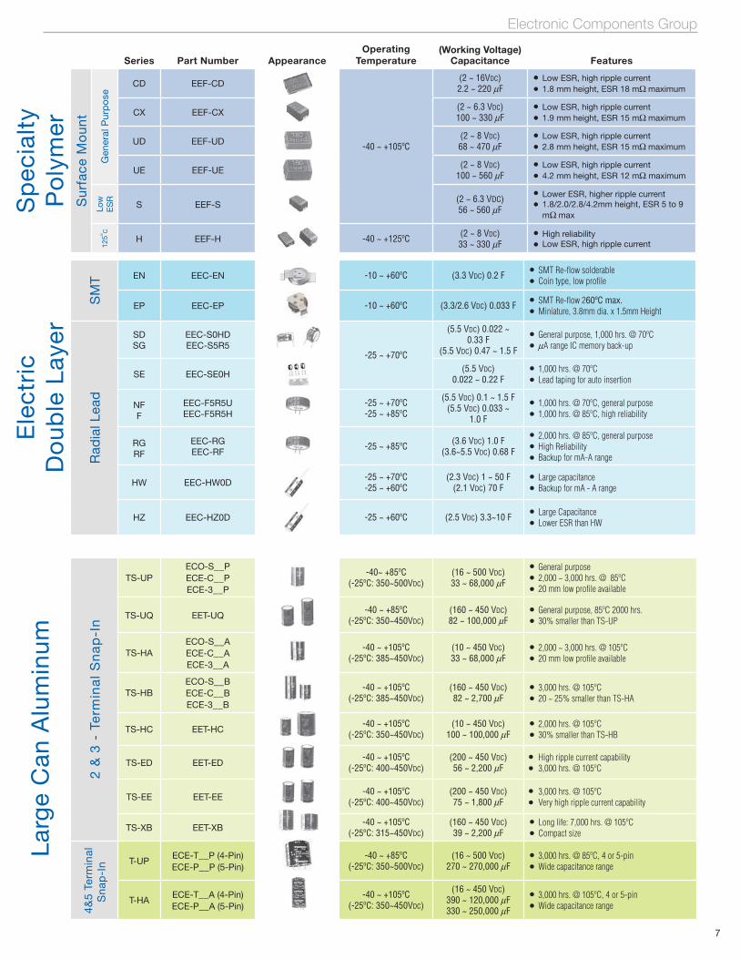
7
Larg
e C
an A
lum
inum
2 &
3 -
Te
rmin
al
Sn
ap
-In
TS-UPECO-S__PECE-C__PECE-3__P
-40~ +85ºC(-25ºC: 350~500VDC)
(16 ~ 500 VDC)33 ~ 68,000 uF
]
]
]
General purpose2,000 ~ 3,000 hrs. @ 85ºC20 mm low profile available
TS-UQ EET-UQ-40 ~ +85ºC
(-25ºC: 350~450VDC)(160 ~ 450 VDC)82 ~ 100,000 uF
]
]
General purpose, 85ºC 2000 hrs.30% smaller than TS-UP
TS-HAECO-S__AECE-C__AECE-3__A
-40 ~ +105ºC(-25ºC: 385~450VDC)
(10 ~ 450 VDC)33 ~ 68,000 uF
]
]
2,000 ~ 3,000 hrs. @ 105ºC20 mm low profile available
TS-HBECO-S__BECE-C__BECE-3__B
-40 ~ +105ºC(-25ºC: 385~450VDC)
(160 ~ 450 VDC)82 ~ 2,700 uF
]
]
3,000 hrs. @ 105ºC20 ~ 25% smaller than TS-HA
TS-HC EET-HC-40 ~ +105ºC
(-25ºC: 350~450VDC)(10 ~ 450 VDC)
100 ~ 100,000 uF]
]
2,000 hrs. @ 105ºC30% smaller than TS-HB
TS-ED EET-ED-40 ~ +105ºC
(-25ºC: 400~450VDC)(200 ~ 450 VDC)56 ~ 2,200 uF
]
]
High ripple current capability3,000 hrs. @ 105ºC
TS-EE EET-EE-40 ~ +105ºC
(-25ºC: 400~450VDC)(200 ~ 450 VDC)75 ~ 1,800 uF
]
]
3,000 hrs. @ 105ºCVery high ripple current capability
TS-XB EET-XB-40 ~ +105ºC
(-25ºC: 315~450VDC)(160 ~ 450 VDC)39 ~ 2,200 uF
]
]
Long life: 7,000 hrs. @ 105ºCCompact size
4&
5 Te
rmin
alS
nap
-In
T-UPECE-T__P (4-Pin)ECE-P__P (5-Pin)
-40 ~ +85ºC(-25ºC: 350~500VDC)
(16 ~ 500 VDC)270 ~ 270,000 uF
]
]
3,000 hrs. @ 85ºC, 4 or 5-pinWide capacitance range
T-HAECE-T__A (4-Pin)ECE-P__A (5-Pin)
-40 ~ +105ºC(-25ºC: 350~450VDC)
(16 ~ 450 VDC)390 ~ 120,000 uF330 ~ 250,000 uF
]
]
3,000 hrs. @ 105ºC, 4 or 5-pinWide capacitance range
Series Part Number AppearanceOperating
Temperature(Working Voltage)
Capacitance Features
Sp
ecia
lty
Po
lym
erS
urfa
ce M
oun
t
Gen
eral
Pur
po
se
CD EEF-CD
-40 ~ +105ºC
(2 ~ 16VDC)2.2 ~ 220 uF
]
]
Low ESR, high ripple current1.8 mm height, ESR 18 mo maximum
CX EEF-CX(2 ~ 6.3 VDC)100 ~ 330 uF
]
]
Low ESR, high ripple current1.9 mm height, ESR 15 mo maximum
UD EEF-UD(2 ~ 8 VDC)68 ~ 470 uF
]
]
Low ESR, high ripple current2.8 mm height, ESR 15 mo maximum
UE EEF-UE(2 ~ 8 VDC)
100 ~ 560 uF]
]
Low ESR, high ripple current4.2 mm height, ESR 12 mo maximum
Low
ES
R
S EEF-S(2 ~ 6.3 VDC)56 ~ 560 uF
]
]
Lower ESR, higher ripple current1.8/2.0/2.8/4.2mm height, ESR 5 to 9 mo max
125º
C
H EEF-H -40 ~ +125ºC (2 ~ 8 VDC)33 ~ 330 uF
]
]
High reliabilityLow ESR, high ripple current
Ele
ctri
cD
oub
le L
ayer
SM
T EN EEC-EN -10 ~ +60ºC (3.3 VDC) 0.2 F]
]
SMT Re-flow solderableCoin type, low profile
EP EEC-EP -10 ~ +60ºC (3.3/2.6 VDC) 0.033 F]
]
SMT Re-flow 260ºC max.Miniature, 3.8mm dia. x 1.5mm Height
Rad
ial L
ead
SDSG
EEC-S0HDEEC-S5R5
-25 ~ +70ºC
(5.5 VDC) 0.022 ~ 0.33 F
(5.5 VDC) 0.47 ~ 1.5 F
]
]
General purpose, 1,000 hrs. @ 70ºCuA range IC memory back-up
SE EEC-SE0H(5.5 VDC)
0.022 ~ 0.22 F]
]
1,000 hrs. @ 70ºCLead taping for auto insertion
NFF
EEC-F5R5UEEC-F5R5H
-25 ~ +70ºC-25 ~ +85ºC
(5.5 VDC) 0.1 ~ 1.5 F(5.5 VDC) 0.033 ~
1.0 F
]
]
1,000 hrs. @ 70ºC, general purpose1,000 hrs. @ 85ºC, high reliability
RGRF
EEC-RGEEC-RF
-25 ~ +85ºC (3.6 VDC) 1.0 F(3.6~5.5 VDC) 0.68 F
]
]
]
2,000 hrs. @ 85ºC, general purposeHigh ReliabilityBackup for mA-A range
HW EEC-HW0D-25 ~ +70ºC-25 ~ +60ºC
(2.3 VDC) 1 ~ 50 F(2.1 VDC) 70 F
]
]
Large capacitanceBackup for mA - A range
HZ EEC-HZ0D -25 ~ +60ºC (2.5 VDC) 3.3~10 F]
]
Large CapacitanceLower ESR than HW
Page 8
8
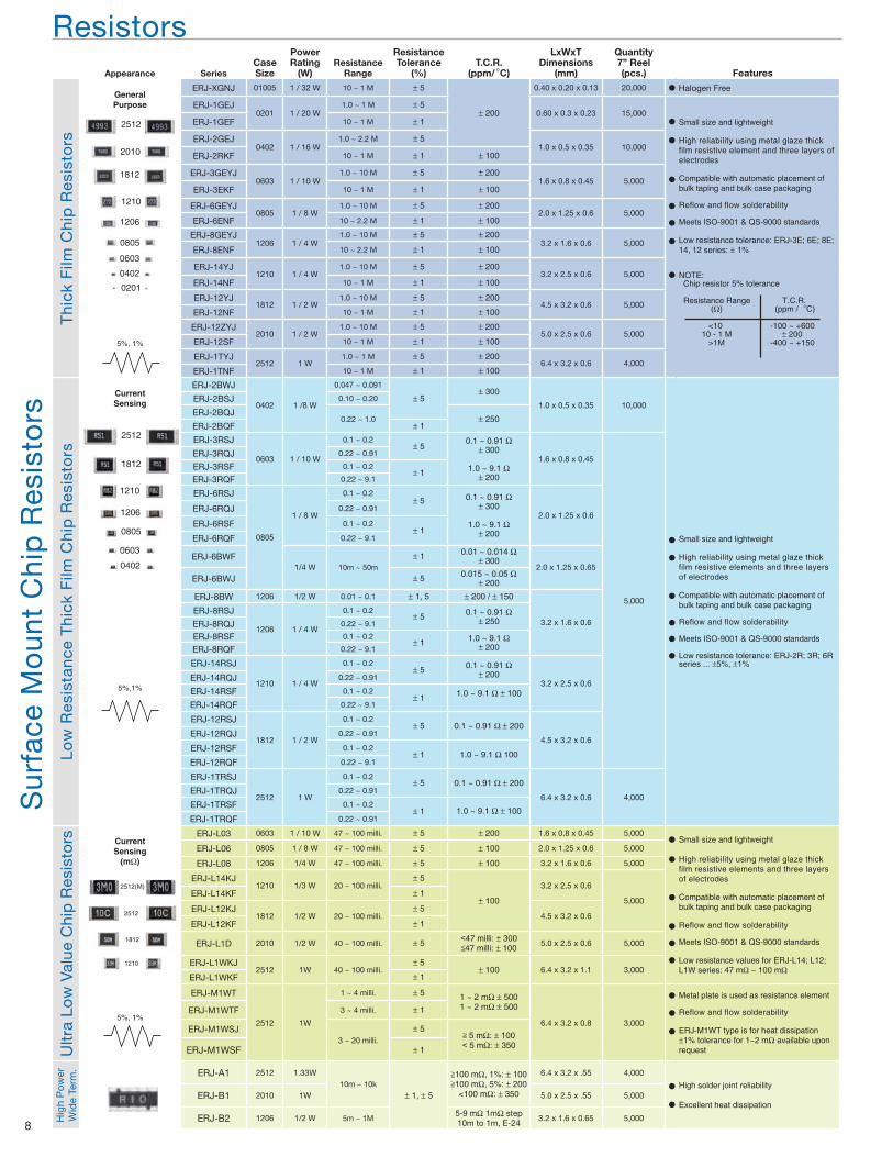
ResistorsAppearance Series
CaseSize
PowerRating
(W)Resistance
Range
ResistanceTolerance
(%)T.C.R.
(ppm/dC)
LxWxTDimensions
(mm)
Quantity7” Reel (pcs.) Features
Sur
face
Mo
unt
Chi
p R
esis
tors
Thi
ck F
ilm C
hip
Res
isto
rs
GeneralPurpose
5%, 1%
ERJ-XGNJ 01005 1 / 32 W 10 ~ 1 M * 5
* 200
0.40 x 0.20 x 0.13 20,000
]
]
]
]
]
]
]
Small size and lightweight
High reliability using metal glaze thick film resistive element and three layers of electrodes
Compatible with automatic placement of bulk taping and bulk case packaging
Reflow and flow solderability
Meets ISO-9001 & QS-9000 standards
Low resistance tolerance: ERJ-3E; 6E; 8E; 14, 12 series: * 1%
NOTE: Chip resistor 5% tolerance
Resistance Range T.C.R. (o) (ppm /dC)
<10 -100 ~ +600 10 - 1 M * 200 >1M -400 ~ +150
ERJ-1GEJ0201 1 / 20 W
1.0 ~ 1 M * 50.60 x 0.3 x 0.23 15,000
ERJ-1GEF 10 ~ 1 M * 1
ERJ-2GEJ0402 1 / 16 W
1.0 ~ 2.2 M * 51.0 x 0.5 x 0.35 10,000
ERJ-2RKF 10 ~ 1 M * 1 * 100
ERJ-3GEYJ0603 1 / 10 W
1.0 ~ 10 M * 5 * 2001.6 x 0.8 x 0.45 5,000
ERJ-3EKF 10 ~ 1 M * 1 * 100
ERJ-6GEYJ0805 1 / 8 W
1.0 ~ 10 M * 5 * 2002.0 x 1.25 x 0.6 5,000
ERJ-6ENF 10 ~ 2.2 M * 1 * 100
ERJ-8GEYJ1206 1 / 4 W
1.0 ~ 10 M * 5 * 2003.2 x 1.6 x 0.6 5,000
ERJ-8ENF 10 ~ 2.2 M * 1 * 100
ERJ-14YJ1210 1 / 4 W
1.0 ~ 10 M * 5 * 2003.2 x 2.5 x 0.6 5,000
ERJ-14NF 10 ~ 1 M * 1 * 100
ERJ-12YJ1812 1 / 2 W
1.0 ~ 10 M * 5 * 2004.5 x 3.2 x 0.6 5,000
ERJ-12NF 10 ~ 1 M * 1 * 100
ERJ-12ZYJ2010 1 / 2 W
1.0 ~ 10 M * 5 * 2005.0 x 2.5 x 0.6 5,000
ERJ-12SF 10 ~ 1 M * 1 * 100
ERJ-1TYJ2512 1 W
1.0 ~ 1 M * 5 * 2006.4 x 3.2 x 0.6 4,000
ERJ-1TNF 10 ~ 1 M * 1 * 100
Low
Res
ista
nce
Thi
ck F
ilm C
hip
Res
isto
rs
CurrentSensing
5%,1%
ERJ-2BWJ
0402 1 /8 W
0.047 ~ 0.091
* 5* 300
1.0 x 0.5 x 0.35 10,000
]
]
]
]
]
]
Small size and lightweight
High reliability using metal glaze thick film resistive elements and three layers of electrodes
Compatible with automatic placement of bulk taping and bulk case packaging
Reflow and flow solderability
Meets ISO-9001 & QS-9000 standards
Low resistance tolerance: ERJ-2R; 3R; 6R series ... *5%, *1%
ERJ-2BSJ 0.10 ~ 0.20
ERJ-2BQJ0.22 ~ 1.0 * 250
ERJ-2BQF * 1
ERJ-3RSJ
0603 1 / 10 W
0.1 ~ 0.2* 5
0.1 ~ 0.91 o* 300
1.0 ~ 9.1 o* 200
1.6 x 0.8 x 0.45
5,000
ERJ-3RQJ 0.22 ~ 0.91
ERJ-3RSF 0.1 ~ 0.2* 1
ERJ-3RQF 0.22 ~ 9.1
ERJ-6RSJ
0805
1 / 8 W
0.1 ~ 0.2* 5 0.1 ~ 0.91 o
* 300
1.0 ~ 9.1 o* 200
2.0 x 1.25 x 0.6ERJ-6RQJ 0.22 ~ 0.91
ERJ-6RSF 0.1 ~ 0.2* 1
ERJ-6RQF 0.22 ~ 9.1
ERJ-6BWF1/4 W 10m ~ 50m
* 1 0.01 ~ 0.014 o* 300
2.0 x 1.25 x 0.65ERJ-6BWJ * 5 0.015 ~ 0.05 o
* 200
ERJ-8BW 1206 1/2 W 0.01 ~ 0.1 * 1, 5 * 200 / * 150
3.2 x 1.6 x 0.6ERJ-8RSJ
1206 1 / 4 W
0.1 ~ 0.2* 5 0.1 ~ 0.91 o
* 250ERJ-8RQJ 0.22 ~ 9.1
ERJ-8RSF 0.1 ~ 0.2* 1 1.0 ~ 9.1 o
* 200ERJ-8RQF 0.22 ~ 9.1
ERJ-14RSJ
1210 1 / 4 W
0.1 ~ 0.2* 5 0.1 ~ 0.91 o
* 2003.2 x 2.5 x 0.6
ERJ-14RQJ 0.22 ~ 0.91
ERJ-14RSF 0.1 ~ 0.2* 1 1.0 ~ 9.1 o * 100
ERJ-14RQF 0.22 ~ 9.1
ERJ-12RSJ
1812 1 / 2 W
0.1 ~ 0.2* 5 0.1 ~ 0.91 o * 200
4.5 x 3.2 x 0.6ERJ-12RQJ 0.22 ~ 0.91
ERJ-12RSF 0.1 ~ 0.2* 1 1.0 ~ 9.1 o 100
ERJ-12RQF 0.22 ~ 9.1
ERJ-1TRSJ
2512 1 W
0.1 ~ 0.2* 5 0.1 ~ 0.91 o * 200
6.4 x 3.2 x 0.6 4,000ERJ-1TRQJ 0.22 ~ 0.91
ERJ-1TRSF 0.1 ~ 0.2* 1 1.0 ~ 9.1 o * 100
ERJ-1TRQF 0.22 ~ 0.91
Ultr
a Lo
w V
alue
Chi
p R
esis
tors Current
Sensing(mo)
5%, 1%
ERJ-L03 0603 1 / 10 W 47 ~ 100 milli. * 5 * 200 1.6 x 0.8 x 0.45 5,000]
]
]
]
]
]
Small size and lightweight
High reliability using metal glaze thick film resistive elements and three layers of electrodes
Compatible with automatic placement of bulk taping and bulk case packaging
Reflow and flow solderability
Meets ISO-9001 & QS-9000 standards
Low resistance values for ERJ-L14; L12; L1W series: 47 mo ~ 100 mo
ERJ-L06 0805 1 / 8 W 47 ~ 100 milli. * 5 * 100 2.0 x 1.25 x 0.6 5,000
ERJ-L08 1206 1/4 W 47 ~ 100 milli. * 5 * 100 3.2 x 1.6 x 0.6 5,000
ERJ-L14KJ1210 1/3 W 20 ~ 100 milli.
* 5
* 100
3.2 x 2.5 x 0.6
5,000ERJ-L14KF * 1
ERJ-L12KJ1812 1/2 W 20 ~ 100 milli.
* 54.5 x 3.2 x 0.6
ERJ-L12KF * 1
ERJ-L1D 2010 1/2 W 40 ~ 100 milli. * 5,47 milli: * 300<47 milli: * 100
5.0 x 2.5 x 0.6 5,000
ERJ-L1WKJ2512 1W 40 ~ 100 milli.
* 5* 100 6.4 x 3.2 x 1.1 3,000
ERJ-L1WKF * 1
ERJ-M1WT
2512 1W
1 ~ 4 milli. * 5 1 ~ 2 mo * 5001 ~ 2 mo * 500
6.4 x 3.2 x 0.8 3,000
]
]
]
Metal plate is used as resistance element
Reflow and flow solderability
ERJ-M1WT type is for heat dissipation*1% tolerance for 1~2 mo available upon request
ERJ-M1WTF 3 ~ 4 milli. * 1
ERJ-M1WSJ3 ~ 20 milli.
* 5> 5 mo: * 100, 5 mo: * 350ERJ-M1WSF * 1
Hig
h P
ow
erW
ide
Term
. ERJ-A1 2512 1.33W10m ~ 10k
* 1, * 5
>100 mo, 1%: * 100>100 mo, 5%: * 200
<100 mo: * 350
6.4 x 3.2 x .55 4,000
]
]
High solder joint reliability
Excellent heat dissipationERJ-B1 2010 1W 5.0 x 2.5 x .55 5,000
ERJ-B2 1206 1/2 W 5m ~ 1M5-9 mo 1mo step10m to 1m, E-24
3.2 x 1.6 x 0.65 5,000
2512
2010
1812
1210
1206
0805
0603
0201
0402
2512(M)
2512
1812
1210
2512
1812
1210
1206
0805
0603
0402
] Halogen Free
Page 9
Electronic Components Group
9
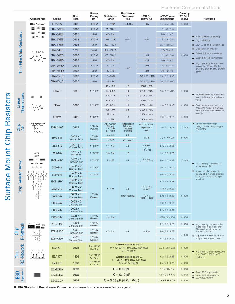
[ EIA Standard Resistance Values E-96 Tolerance *1% | E-24 Tolerance *5%, 0.5%, 0.1%
Appearance SeriesCaseSize
PowerRating
(W)Resistance
Range
ResistanceTolerance
(%)T.C.R.
(ppm/dC)LxWxT (mm)Dimensions
Quantity7” Reel (pcs.) Features
Sur
face
Mo
unt
Chi
p R
esis
tors
Thi
n F
ilm C
hip
Res
isto
rsUltra Precision ERA-2A 0402 1/16 W 10 ~ 100K * 0.1, 0.5 * 25 1.0 x 0.5 x 0.35 10,000
]
]
]
]
]
]
]
Small size and lightweight
High reliability
Low T.C.R. and current noise
Excellent non-linearity
Reflow & flow solderability
Meets ISO-9001 standards
High operating temperature capability -55 to +155 for ERA-2A, ERA-3A and ERA6A types
ERA-3AEB 0603 1/10 W 47 ~ 330 K
* 0.1 * 25
1.6 x .80 x 0.45
5,000
ERA-6AEB 0805 1/8 W 47 ~ 1 M 2.0 x 1.25 x .5
ERA-3YEB 0603 1/10 W 100 ~ 33 K 1.6 x 0.8 x 0.45
EBA-6YEB 0805 1/8 W 100 ~ 100 K 2.0 x 1.25 x 0.5
ERA-14EB 1210 1/4 W 100 ~ 200 K 3.2 x 2.5 x 0.6
ERA-3AED 0603 1/10 W 47 ~ 330 K
* 0.5
* 25 1.6 x .80 x 0.45
ERA-6AED 0805 1/8 W 47 ~ 1 M * 25 2.0 x 1.25 x .5
ERA-3AHD 0603 1/10 W 10 ~ 43 * 50 1.6 x .80 x 0.45
ERA-6AHD 0805 1/8 W 10 ~ 43 * 50 2.0 x 1.25 x .5
ERA-3Y_D 0603 1/10 W 10 ~ 330K * 50, * 25, * 100 1.6 x 0.8 x 0.45
ERA-6Y_D 0805 1/8 W 10 ~ 1M * 50, * 25, * 100 2.0 x 1.25 x 0.5
Line
ar
The
rmis
tors
ERAS 0805 1 / 10 W
10 ~ 10 K * 5 1500 * 200
2.0 x 1.25 x 0.5 5,000]
]
Excellent linearity of tempera-ture coefficient to resistance value
Good for temperature com-pensation circuit in applica-tions such as VRM and/or PA module
43 ~ 5.1 K * 5 2700 * 10%
6.2 ~ 470 * 5 3900 * 10%
ERAV 0603 1 / 16 W
10 ~ 10 K * 5 1500 * 200
1.6 x 0.8 x 0.45 5,00043 ~ 3.3 K * 5 2700 * 10%
7.5 ~ 390 * 5 3900 * 10%
ERAW 0402 1 / 32 W43 ~ 1K
* 52700 * 10%
1.0 x 0.5 x 0.35 10,00022 ~ 390 3300 * 10%
Chi
pA
tt. Chip Attenuator
EXB-24AT 04041 / 25 W Package
Attenuation Range
1 ~ 5 dB 6 ~ 10 dB
AttenuationTolerance* 0.3 dB* 0.5 dB
Characteristic Impedance
50 o1.0 x 1.0 x 0.35
]
]
High density of resistors in single array chip
Improved placement effi-ciency (2 to 4 times greater) compared to flat chip type resistors
Chi
p R
esis
tor
Arr
ay
ERA-38V 0603 x 4Convex Term
1 / 16 WElement
100K~220K
1K~100K
0.5
0.1, 0.25* 25 3.2 x 1.6 x 0.5
EXB-14V 0201 x 2Convex Term
1 / 32 W 10 ~ 1 M * 5 * 200 x
10-6
/dC
1 - 10o:* 600/-100x10-6/dC
0.8 x 0.6 x 0.35
EXB-18V 0201 x 4Flat Term
1 / 32 W 10 ~ 1 M * 5 1.4 x 0.6 x 0.35
EXB-N8V 0402 x 4Concave Term
1 / 32 W 1 ~ 1 M * 5 2.0 x 1.0 x 0.45
EXB-24V 0402 x 2 Convex Term
1 / 16 W
1 ~ 1 M * 5
* 1upon request
10 - 1 M : * 200
10 > : -100 - + 600
1.0 x 1.0 x 0.35
EXB-28V 0402 x 4 Convex Term
1 / 32 W 2.0 x 1.0 x 0.35
EXB-2HV 0402 x 8 Convex Term
1 / 16 W Element
3.8 x 1.6 x 0.45
5,000
EXB-34V 0603 x 2 Convex Term
1.6 x 1.6 x 0.50
EXB-38V 0603 x 4 Convex Term
3.2 x 1.6 x 0.50
EXB-V4V 0603 x 2 Concave Term
1.6 x 1.6 x 0.60
EXB-V8V 0603 x 4 Concave Term
3.2 x 1.6 x 0.60
EXB-S8V 0805 x 4 Concave Term
1 / 10 W Element
10 ~ 1 M 5.08 x 2.2 x 0.70 2,500
Chip
R-Ne
twor
k EXB-D10C 1206Concave Term
1 / 20 W Element
47 ~ 1 M * 5 * 200
3.2 x 1.6 x 0.55 5,000 ]
]
High density placement for digital signal applications: 8 bussed resistors for pull up/down circuits
Superior mountability due to unique concave terminal
EXB-E10C 1608Concave Term
1 / 16 W Element 4.0 x 2.1 x 0.55
4,000
EXB-A10P 2512 Concave Term
1 / 16 W Element 6.4 x 3.1 x 0.55
Chip
RC-N
etwo
rk EZA-CT 0805 R = 1 / 32 WC = 12 V
Combination of R and CR = 10, 22, 47, 100, 220, 470, 1Ko
C = 10, 22 pF2.0 x 1.25 x 0.55 5,000
] R-C filters for noise reduction in an 0805, 1206 & 1608 packageEZA-DT 1206 R = 1 / 16 W
C = 12 V Combination of R and CR = 22, 47, 100, 220, 470, 1Ko
C = 22, 47 100 pF
3.2 x 1.6 x 0.65 5,000
EZA-ST 1608 R = 1 / 16 WC = 25 V 4.0 x 2.1 x 0.65 4,000
ESD
Supp
ress
ors EZAEG3A 0603 C = 0.05 pF 1.6 x .80 x 0.5 5,000
]]]
Good ESD suppressionGood ESD withstandingLow capacitance
EZAEG2A 0402 C = 0.10 pF 1.0 x 0.5 x 0.38 10,000
EZAEGCA 0805 C = 0.25 pF (4 Per Pkg.) 2.6 x 1.85 x 0.5 5,000
2512 1608 1206
1210
1206
0805
0.1 %, 0.5 %
8R
4R
2R
02010402
5,000
10,000
Space saving design using unbalanced pie-type attenuator
]
10,000
Page 10
10
Dielectric Series AppearanceOperating
Temperature Ratings Features Applications
Inte
rfer
ence
Sup
pre
sso
rs(s
afet
y st
and
ard
ap
pro
val c
apac
itors
)
Met
alliz
ed P
oly
este
r ECQ-U(Y)
-40 ~ +100ºC
0.001 ~ 0.047 uF250 VAC
• UL, CSA, SEMKO, DEMKO, NEMKO, FIMKO, VDE, SEV approved (Class Y)
• Universal applications• Interference suppression
ECQ-U(G)
0.01 ~ 1.0 uF250 VAC (UL, CSA)
300 VAC(IEC384-14)
• Flame retardant case• Equipped with safety mechanism• UL, CSA, SEMKO, DEMKO, NEMKO, FIMKO, VDE, SEV approved (Class X1)
• Noise suppressor for AC line
ECQ-U(L)
0.01 ~ 2.2 uF250 VAC (UL, CSA)
275 VAC(IEC384-14)
• Smaller size than ECQ-U(V) or ECQ-U(G)• UL, CSA, BDE approved (Class X2)
• High performance, fuse function type in AC line
AC
Use
Met
alliz
edP
oly
este
r/P
oly
pro
pyl
ene
ECH-A(X) -25 ~ +70ºC0.5 ~ 6 uF
180 ~ 430 VAC
• Flame retardant epoxy coating• Equipped with safety mechanism
• Motors
Film CapacitorsG
ener
al A
pp
licat
ions
....
. Dielectric Series AppearanceOperating
Temperature Ratings Features Applications
Chi
p T
ype
StackedMetallized
ECH-U(X)
-55 ~ +125ºC
0.0001 ~ 0.1 uF10/16/50 VDC
• Non-inductive, stacked• Miniature• Reflow soldering• Tight C-tolerance
• High density mounting SMD (industrial grade)
ECH-U(C) 0.047~0.22 uF50/100 VDC
• Non-inductive, stacked• Miniature• Reflow and flow solderability• Tight C-tolerance
• High density mounting SMD• Industrial Use• Filters; oscillators
ECW-U(C) -55 ~ +105ºC-40 ~ +85ºC
0.001 ~ 1.0 uF16/50/100/250
VDC
• Non-inductive, stacked• Miniature• Similar to polyester film cap
• High density mounting SMD (commercial grade)
ECW-U(V16) -55 ~ +85ºC
0.001 ~ 0.15 uF
250/400/600 VDC
• Non-inductive, stacked• Miniature• Similar to polyester film cap
• High density mounting SMD (commercial grade)
ECW-U(X) -55 ~ +105ºC0.001 ~ 0.01
uF100 VDC
• Non-inductive, stacked• Reflow soldering
• Electronic exchange• Ringer circuit telephone & PBX
ECP-U(A) -40 ~ +85ºC 0.1 ~ 1.0 uF16 VDC
• Non-inductive, stacked• Most miniaturized• Reflow soldering
• Coupling, filtering &PLL
Page 11
Electronic Components Group
11
Po
lyp
rop
ylen
e
ECW-F(L) -25 ~ +105ºC0.022 ~ 2.4 uF, 400
VDC
0.01 ~ 1.3 uF, 630 VDC
• Low Dissipation Factor• High Voltage • High frequency, high current
circuits
ECW-F(B)-25 ~ +85ºC
0.022 ~ 0.47 uF250/400 VDC
• Low Dissipation Factor
ECW-H(V) 0.001 ~ 0.1 uF800 ~ 2000 VDC
• Low Dissipation Factor• High pulse circuits(TV, display, electronic balast)
ECW-F(A) -40 ~ 105ºC0.1 ~ 6.8 uF
250 VDC
• Miniaturized Size• High Reliability Design
• High frequency, high current circuits
ECW-H(U)
700 VAC:-40 ~ +100ºC
800 VAC:-40 ~ +85ºC
0.001 ~ 0.0068 uF700/800 VAC
• Low Dissipation Factor• Electronic ballast• Output capacitor
Dielectric Series AppearanceOperating
Temperature Ratings Features Applications
Me
talli
zed
Film
/Fo
il
Stacked
Metallized
ECQ-V
-40 ~ +85ºC
0.01 ~ 2.2 uF50/63/100 VDC
• Non-inductive• Stacked Construction
• General purpose applications• Audio
Po
lyes
ter
ECQ-B 0.0001 ~ 0.47 uF50/63/100 VDC
• Non-inductive• General purpose applications• Audio
ECQ-M 0.001 ~ 0.47 uF400/600 VDC
• Non-inductive • General purpose applications
PP
S
ECH-S -40 ~ +125ºC0.0001 ~ 0.47 uF
50/100 VDC
• Non-inductive• Low temperature coefficient• Tight C-tolerance• High Temperature
• High temperature applications• Oscillation & timing circuits
Po
lyp
rop
ylen
e ECQ-P(Z)
-40 ~ +85ºC
0.0001 ~ 0.47 uF50/100 VDC
• Non-inductive• Tight C-tolerance
• Timing circuits• Temperature compensation• Audio
ECQ-P(U) 0.001 ~ 0.47 uF200/400/630 VDC
• Non-inductive• Epoxy resin coating• Low dissipation factor
• High frequency, high current circuits
ECQ-F -25 ~ +85ºC0.001 ~ 0.47 uF
200/400/630 VDC• Non-inductive
• High frequency, high current circuits
Po
lyes
ter
ECQ-E(H) -40 ~ +105ºC0.47 ~ 2.2 uF
450 VDC
• Smaller Size• Self healing property
• Active filtering circuit
ECQ-E(F)
-40 ~ +85ºC
0.001 ~ 10 uF100 ~ 1250 VDC
• Wide capacitance range• Compact size
• General purpose applications
ECQ-E(B) 0.01 ~ 0.47 uF250 VDC
• Wide capacitance range• Miniaturized
ECQ-E(C) 0.1 ~ 2.2 uF450 VDC
• Flame retardant case • Active filtering circuit
Met
alliz
ed F
ilm
Page 12
12
Series
EIACase Size
Inductance@ 100 MHz
NominalQ Min
@ 100 MHzQ Typical
@ 800 MHz
Rated DC Current
Max. (mA)
DCResistance
(O)SRF
Min. (MHz) Features
Sur
face
Mo
unt
Chi
p I
nduc
tors
H
igh
Fre
que
ncy
Lase
r C
ut
ELJ-RF 0402 1.0 to 100 nH 8 21 to 14 400 to 90 0.05 to 5.5 6000 to 1200 ]
]
]
Non-polarity
Precision inductance
High self-resonant frequencyELJ-RE 0603 1.0 to 220 nH 4 to 12 47 to 20 500 to 70 0.05 to 7.5 6000 to 900
ELJ-PF 0402 2.2 to 10 nH 7 -- 1900 to 750 0.04 to 0.26 5300 to 3200] High current rating for
high-frequency use ELJ-PE 0603 2.2 to 22 nH 8 to 9 -- 2100 to 700 0.03 to 0.15 6000 to 1800
ELJ-QF 0402 1.0 to 39 nH 10 35 to 41 150 to 400 0.05 to 1.7 6000 to 1800 ] High Q
Wire
-Wo
und
ELJ-ND 0805 10 to 1,000 nH 8 to 15 -- 540 to 120 0.18 to 3.88 3300 to 80]
]
Low inductance, tight tolerance
Stable L-value over varied ambient conditions
ELJ-NC 1008 10 to 820 nH 10 to 15 -- 280 to 100 0.32 to 2.1 2500 to 100
ELJ-NA 1210 0.047 to 8.20 uH 10 to 13 -- 450 to 60 0.20 to 11 680 to 38
Gen
eral
Use
ELJ-FC 1008 0.22 to 100 uH 15 to 25 -- 190 to 60 0.70 to 21 230 to 12
] Suitable for general useapplications
ELJ-FA 1210 0.22 to 220 uH 20 to 30 -- 360 to 45 0.29 to 21 230 to 7
ELJ-SA 1210 10 to 270 uH 40 -- 18 to 5 1.80 to 14 30 to 4
ELJ-FB 1812 0.22 to 1,000 uH 30 to 50 -- 700 to 40 0.30 to 53 230 to 2.1
Hig
h C
urre
nt ELJ-PC 1008 1.0 to 33 uH 8 to 20 -- 475 to 120 0.45 to 6.5 95 to 16
]
]
Low DC resistance and high DC current rating
Suitable for use in power lines as a choke coil
ELJ-PA 1210 1.0 to 330 uH 7 to 20 -- 600 to 50 0.15 to 16 150 to 3
ELJ-PB 1812 10 to 220 uH 10 to 20 -- 360 to 90 0.65 to 9 19 to 4
ELJ-EA 1210 1.0 to 330 uH 7 to 20 -- 500 to 30 0.09 to 9.23 100 to 4 ] Very Low DC resistance
Inductors* **
* Q Min. - Please check each specification. ** SRF - Self Resonant Frequency
Page 13
Electronic Components Group
13
J
M
Inductance Range ChartEIA Case Size
(Metric)
Product Type
Hig
h F
req
uenc
y
Lase
r C
utW
ire
- W
oun
d
Gen
eral
Pur
po
seH
igh
Cur
rent
0.001 0.01 0.1 1 10 100 (uH)1000
Inductance Range
0402 (1005)
ELJ-RF
0805 (2012)
ELJ-ND
1008 (2520)
ELJ-NC
1210 (3225)
ELJ-NA
1812 (4532)
ELJ-FB
1008 (2520)
ELJ-PC
1210 (3225)
ELJ-FA
0603 (1608)
ELJ-PE
0603 (1608)
ELJ-RE
0402 (1005)
ELJ-PF
1210 (3225)ELJ-SA
Magnetic Shield
1008 (2520)
ELJ-FC
1210 (3225)
ELJ-PA
1812 (4532)
ELJ-PB
1210 (3225)
ELJ-EA
D/JD/J: 2.2 to 10nH
K
K: 2.2 to 22nH
K
JK: 10 to 1000nH J: 33 to 1000nH
K
JK: 10 to 820nH J: 33 to 820nH
M K J
M: 0.047 to 0.22UH K: 0.22 to 1.0UH J: 1 to 8.2UH
M J
K
M: 0.22 to 0.82UH K: 0.22 to 100UH J: 1 to 100UH
M J
K
M: 0.22 to 1.0UH K: 0.22 to 220UH J: 1 to 220UH
KK: 10 to 270UH
M J
K
M: 0.22 to 10UH K: 1 to 1000UH J: 10 to 1000UH
M KM: 1 to 6.8UH
M K
M: 1 to 10UH K: 10 to 330UH
K
K: 10 to 220UH
KMM: 1 to 10UH K: 10 to 330UH
D
Z G
J
D: 1 to 3.9nH / Z: 1 to 10nH J: 3.9 to 220nH / G: 10 to 220nH
JD
Z GD: 1 to 6.8nH / Z: 1 to 10nH J: 6.8 to 100nH / G: 10 to 100nH
K: 6.8 to 33UH
0402 (1005)
ELJ-QFD: 1 to 6.8nH / Z: 1 to 10nH J: 6.8 to 39nH / G: 10 to 39nH
JD
Z G
Low
DC
R
Z: * 0.2 nH
D: * 0.3 nH
E: * 0.5 nH
G: * 2 %
A: * 3 %
J: * 5 %
K: * 10 %
M: * 20 %
Code Value
Page 14
14
Ceramic CapacitorsSeries Appearance
Case Size(EIA)
OperatingVoltage (VDC)
TemperatureCharacteristics
CapacitanceRange Features
Mul
ti-L
ayer
Cer
amic
Chi
p C
apac
ito
rs (
MLC
C)
Larg
e C
apac
itan
ce V
alue
s ECJ-0 0402 6.3, 10V X5R, Y5V 1 uF to 2.2 uF ]
]
]
]
]
High cap in small case sizes(2.2uF in 0402, 10uF in 0603, 22 uF in 0805)Low ESR/ESLHigh ripple current capabilityHigh reliabilityNon-polarity
ECJ-1 0603 6.3, 10, 16V X5R, Y5V 1 uF to 10 uF
ECJ-2 0805 6.3, 10, 16, 25V X5R, Y5V 1 uF to 22 uF
ECJ-3 1206 6.3, 10, 16, 25V X7R, X5R, Y5V 1 uF to 22 uF
Sta
ndar
d
Cap
acit
ance
Val
ues
ECJ-Z 0201 6.3, 10, 16, 25V
X5R, X7R, Y5V,
C0K, C0J, C0H,
C0G, SL/GP
0.5 pF to 0.22 uF
]
]
]
]
Wide selectionSmall case size (0201)High reliabilityNon-polarity
ECJ-0 04026.3, 10, 16, 25,
50V0.5 pF to 0.47 uF
ECJ-1 06036.3, 10, 16, 25,
50V0.5 pF to 0.47 uF
ECJ-2 08056.3, 10, 16, 25,
50V27 pF to 0.47 uF
ECJ-3 12066.3, 10, 16, 25,
50V3300 pF to 0.68 uF
Low
Pro
file ECJ-G 0805 6.3, 10, 16V
X5R
1 uF to 4.7 uF ] H = 0.85 * 0.1 mm
ECJ-H 1206 6.3, 10V1 uF to 10 uF
2.2 uF to 22 uF] H = 0.85 * 0.1 mm
Rev
erse
-Geo
met
ryW
ide
term
inat
ions
ECY-2 0508 10, 25, 50V
X5R
0.01 uF to 1 uF
] Very low ESR/ESL
ECY-3 0612 6.3, 16, 50V 0.1 uF to 10 uF
Mid
-ran
ge
Volt
ages
ECJ-1__2A0603
100V
C0H, X7R
10 pF to 1000 pF
]
]
]
Suitable for mid-voltage applicationsHigh reliabilityNon-polarity
ECJ-1__2D 200V 220 pF to 1000 pF
ECJ-2__2A0805
100V 10 pF to 0.015 uF
ECJ-2__2D 200V 10 pF to 0.01 uF
ECJ-3__2A1206
100V 1500 pF to 0.1 uF
ECJ-3__2D 200V 470 pF to 0.022 uF
Hig
h Vo
ltag
e
ECJ-3__2J 1206 630V C0H, X7R 100 pF to 0.01 uF ] Suitable for high-voltage applications
Mic
row
ave
(Hig
h Q
)
ECD
0201
25V C0G
0.1 pF to 5.6 pF ]
]
]
Very high Q, at high frequencies (GHz)Tight toleranceWide range up to 15 pF with small steps between values0402 0.1 pF to 15 pF
Arr
ays
ECJ-U 0405 6.3 ~ 50V C0H, X7R, X5R 10 pF to 1 uF] 2 capacitors in 1 pkg for low part
number count
ECJ-T 0805 16, 25, 50V C0H 10 pF to 220 pF
] 4 capacitors in 1 pkg for low part number count
ECJ-T 0805 16, 25, 50V C0H, X7R, Y5V 10 pF to 0.1 uF
ECJ-R 1206 10, 16, 25, 50V C0H, X7R, Y5V 10 pF to 1 uF
Page 15
Electronic Components Group
15
Series Appearance SeriesOperating
VoltageTemperature
Characteristics Capacitance Range Features
Cer
amic
Cap
acit
ors
Hig
h Vo
ltage
(AC
, Pul
se, a
nd L
ow L
oss
Ap
plic
atio
ns)
ECC-_HT____KG HT-KG
500VDC
SL/GP 10 pF to 470 pF] Class I Dielectric with Temperature
Coefficient: +350 to -1000 ppm/
ECK-_HT____KB HT-KB Y5P 100 pF to 4,700 pF] Class II Dielectric with Temperature
Coefficient: *10%
ECK-_HT____KC HT-KC Y5S 100 pF to 4,700 pF] Class II Dielectric with Temperature
Coefficient: *22%
ECC-_3____KGE KGE
1kVDC - 3kVDC
SL/GP 12 pF to 470 pF] Class I Dielectric with Temperature
Coefficient: +350 to -1000 ppm/
ECK-_3____KBP KBP Y5P 100 pF to 5,600 pF] Class II Dielectric with Temperature
Coefficient: *10%
ECK-_3____KRP KRP Y5R 100 pF to 4,700 pF] Class II Dielectric with Temperature
Coefficient: *22%
Hig
h Vo
ltage
(DC
Ap
plic
atio
ns)
ECK-_S____KB KB1kVDC - 3kVDC
Y5P 100 pF to 4,700 pF ] From 6 mm to 14.5 mm in size
ECK-_3____MEH MEH Y5U 680 pF to 0.01 uF ] From 7 mm to 16.5 mm in size
ECK-D4____MDV MDV10, 12, 15kVDC
Y5T 100 pF to 0.01 UF ] Very high voltage ratings
ECC-T3
Hi-V SMD1kVDC - 5kVDC
SL/GP 10 pF to 68 pF]Molded SMD case for
reflow solderingECK-T3 Y5P 100 pF to 470 pF
Inte
rfer
ence
Sup
pre
ssio
n ‘S
afet
y’ C
apac
itors
ECK-_NA NS-A
250 / 440VAC
Y5P, Y5U 100 pF to 4,700 pF] UL/CSA/IEC X1/Y1 approval,
4000 VAC for 1 minute
ECK-_TS TS Y5P, Y5U, Y5V 100 pF to 0.01 uF] UL/CSA/IEC X1/Y2 approval,
2600 VAC for 1 minute
ECK-_VS VS
GP/SL 10 pF to 68 pF ]
]
UL/CSA/SEMCO X1/Y2 approval, 1500 VAC for 1 minute 5 mm lead spacingY5P, Y5U, Y5V 100 pF to 4,700 pF
ECC-TBC
BC 250VAC
SL/GP 10 pF to 68 pF ]
]
UL(CSA)/SEMCO Y2 approval, 1500 VAC for 1 minuteSMD (7.1 x 6.3 x 2.5 mm)ECK-TBC Y5P, Y5U, Y5V 100 pF to 4,700 pF
ECC-TFC
FC 250VAC
SL/GP 5 pF to 330 pF ]
]
UL(CSA)/SEMCO Y2 approval, 1500 VAC for 1 minute SMD, small size (5.7 x 4.5 x 2.3 mm)ECK-TFC Y5P, Y5U, Y5V 470 pF to 4,700 pF
dC
dC
Page 16
16
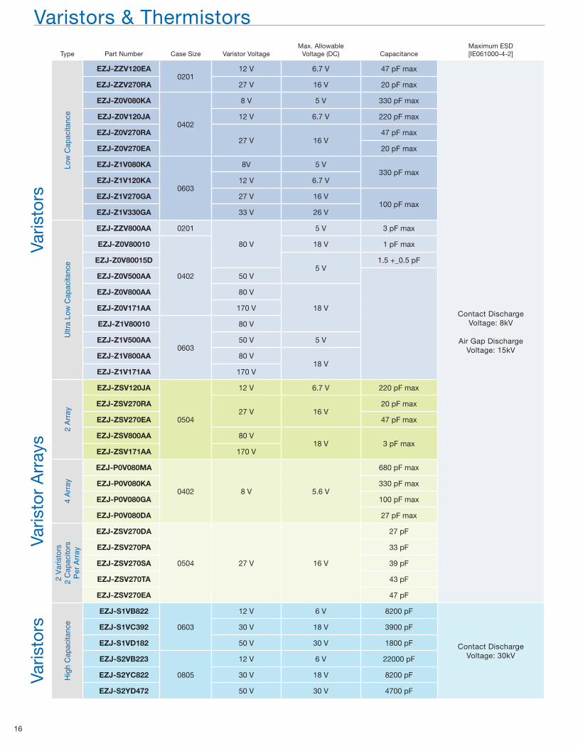
Varistors & Thermistors
Type Part Number Case Size Varistor VoltageMax. Allowable
Voltage (DC) CapacitanceMaximum ESD[IE061000-4-2]
Varis
tors
Low
Cap
acita
nce
EZJ-ZZV120EA0201
12 V 6.7 V 47 pF max
Contact Discharge Voltage: 8kV
Air Gap DischargeVoltage: 15kV
EZJ-ZZV270RA 27 V 16 V 20 pF max
EZJ-Z0V080KA
0402
8 V 5 V 330 pF max
EZJ-Z0V120JA 12 V 6.7 V 220 pF max
EZJ-Z0V270RA27 V 16 V
47 pF max
EZJ-Z0V270EA 20 pF max
EZJ-Z1V080KA
0603
8V 5 V330 pF max
EZJ-Z1V120KA 12 V 6.7 V
EZJ-Z1V270GA 27 V 16 V100 pF max
EZJ-Z1V330GA 33 V 26 V
Ultr
a Lo
w C
apac
itanc
e
EZJ-ZZV800AA 0201
80 V
5 V 3 pF max
EZJ-Z0V80010
0402
18 V 1 pF max
EZJ-Z0V80015D5 V
1.5 +_0.5 pF
EZJ-Z0V500AA 50 V
EZJ-Z0V800AA 80 V
18 VEZJ-Z0V171AA 170 V
EZJ-Z1V80010
0603
80 V
EZJ-Z1V500AA 50 V 5 V
EZJ-Z1V800AA 80 V18 V
EZJ-Z1V171AA 170 V
Varis
tor
Arr
ays
2 A
rray
EZJ-ZSV120JA
0504
12 V 6.7 V 220 pF max
EZJ-ZSV270RA27 V 16 V
20 pF max
EZJ-ZSV270EA 47 pF max
EZJ-ZSV800AA 80 V18 V 3 pF max
EZJ-ZSV171AA 170 V
4 A
rray
EZJ-P0V080MA
0402 8 V 5.6 V
680 pF max
EZJ-P0V080KA 330 pF max
EZJ-P0V080GA 100 pF max
EZJ-P0V080DA 27 pF max
2 V
aris
tors
2 C
apac
itors
Per
Arr
ay
EZJ-ZSV270DA
0504 27 V 16 V
27 pF
EZJ-ZSV270PA 33 pF
EZJ-ZSV270SA 39 pF
EZJ-ZSV270TA 43 pF
EZJ-ZSV270EA 47 pF
Varis
tors
Hig
h C
apac
itanc
e
EZJ-S1VB822
0603
12 V 6 V 8200 pF
Contact DischargeVoltage: 30kV
EZJ-S1VC392 30 V 18 V 3900 pF
EZJ-S1VD182 50 V 30 V 1800 pF
EZJ-S2VB223
0805
12 V 6 V 22000 pF
EZJ-S2YC822 30 V 18 V 8200 pF
EZJ-S2YD472 50 V 30 V 4700 pF
Page 17
Electronic Components Group
17
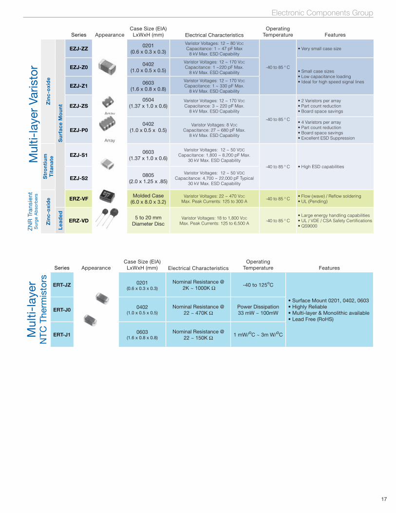
Series AppearanceCase Size (EIA)
LxWxH (mm) Electrical CharacteristicsOperating
Temperature FeaturesM
ulti-
laye
r Va
risto
rZ
inc
-oxi
de
Su
rfa
ce
Mo
un
t
EZJ-ZZ 0201(0.6 x 0.3 x 0.3)
Varistor Voltages: 12 ~ 80 VDC
Capacitance: 1 ~ 47 pF Max8 kV Max. ESD Capability
-40 to 85 º C
• Very small case size
EZJ-Z0 0402(1.0 x 0.5 x 0.5)
Varistor Voltages: 12 ~ 170 VDC
Capacitance: 1 ~220 pF Max.8 kV Max. ESD Capability • Small case sizes
• Low capacitance loading• Ideal for high speed signal lines
EZJ-Z1 0603(1.6 x 0.8 x 0.8)
Varistor Voltages: 12 ~ 170 VDC
Capacitance: 1 ~ 330 pF Max.8 kV Max. ESD Capability
EZJ-ZSArray
0504(1.37 x 1.0 x 0.6)
Varistor Voltages: 12 ~ 170 VDC
Capacitance: 3 ~ 220 pF Max.8 kV Max. ESD Capability
-40 to 85 º C
• 2 Varistors per array• Part count reduction• Board space savings
EZJ-P0
Array
0402(1.0 x 0.5 x 0.5)
Varistor Voltages: 8 VDC
Capacitance: 27 ~ 680 pF Max.8 kV Max. ESD Capability
• 4 Varistors per array• Part count reduction• Board space savings• Excellent ESD Suppression
Str
on
tiu
m
Tit
an
ate
EZJ-S1 0603(1.37 x 1.0 x 0.6)
Varistor Voltages: 12 ~ 50 VDCCapacitance: 1,800 ~ 8,200 pF Max.
30 kV Max. ESD Capability-40 to 85 º C • High ESD capabilities
EZJ-S2 0805(2.0 x 1.25 x .85)
Varistor Voltages: 12 ~ 50 VDCCapacitance: 4,700 ~ 22,000 pF Typical
30 kV Max. ESD Capability
ZN
R T
rans
ient
Sur
ge
Ab
sorb
ers
Zin
c-o
xid
e ERZ-VF Molded Case(6.0 x 8.0 x 3.2)
Varistor Voltages: 22 ~ 470 VDC
Max. Peak Currents: 125 to 300 A -40 to 85 º C• Flow (wave) / Reflow soldering• UL (Pending)
Le
ad
ed
ERZ-VD 5 to 20 mmDiameter Disc
Varistor Voltages: 18 to 1,800 VDC
Max. Peak Currents: 125 to 6,500 A -40 to 85 º C• Large energy handling capabilities • UL / VDE / CSA Safety Certifications• QS9000
Series AppearanceCase Size (EIA)
LxWxH (mm)
Electrical CharacteristicsOperating
Temperature Features
Mul
ti-la
yer
NTC
The
rmis
tors
ERT-JZ 0201(0.6 x 0.3 x 0.3)
Nominal Resistance @ 2K ~ 1000K O
-40 to 125oC
• Surface Mount 0201, 0402, 0603• Highly Reliable• Multi-layer & Monolithic available• Lead Free (RoHS)
ERT-J0 0402(1.0 x 0.5 x 0.5)
Nominal Resistance @22 ~ 470K O
Power Dissipation33 mW ~ 100mW
ERT-J1 0603(1.6 x 0.8 x 0.8)
Nominal Resistance @22 ~ 150K O
1 mW/oC ~ 3m W/oC
Page 18
18
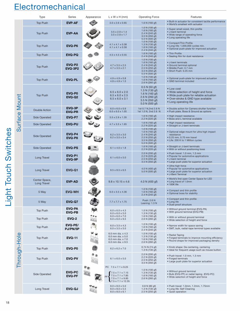
Type Series Appearance L x W x H (mm) Operating Force FeaturesS
urfa
ce M
oun
tTop Push EVP-AF 3.0 x 2.6 x 0.65 1.6 N (160 gf)
• Built-in actuator for consistent tactile performance• World’s smallest with actuator
Top Push EVP-AA 3.5 x 2.9 x 1.43.5 x 2.9 x 1.7
1.0 N (100 gf)1.6 N (160 gf)2.4 N (240 gf)3.5 N (350 gf)5.0 N (500 gf)
• Super small-sized, thin profile• J-bent terminal• Wide range of operating force• Long operating life
Lig
ht T
ouc
h S
wit
ches
Top Push EVQ-P6 4.1 x 4.1 x 0.384.1 x 4.1 x 0.58
1.0 N (100 gf)1.3 N (130 gf)1.6 N (160 gf)2.4 N (240 gf)
• Compact/Thin Profile• Long-life: 1,000,000 cycles min.• Optional push-plate for improved actuation
Top Push EVQ-PQ 4.5 x 4.5 x 0.551.6 N (160 gf)2.4 N (240 gf)
• Thin Profile• Sealing film for dust resistance
Top PushEVQ-P2EVQ-3P2
4.7 x 3.5 x 2.54.7 x 3.5 x 2.1
1.0 N (100 gf)1.6 N (160 gf)2.4 N (240 gf)2.5 N (250 gf)3.5 N (350 gf)5.0 N (500 gf)
• J-bent terminals• Ground terminal optional• Middle Push: 0.7 mm• Short Push: 0.25 mm
Top Push EVQ-PL 4.9 x 4.9 x 0.84.9 x 4.9 x 1.5
1.0 N (100 gf)1.6 N (160 gf)2.6 N (260 gf)
• Optional push-plate for improved actuation• GND terminal included
Top PushEVQ-P0EVQ-Q2
6.5 x 6.0 x 2.06.5 x 6.0 x 2.56.5 x 6.0 x 3.1
0.5 N (50 gf)1.3 N (130 gf)1.6 N (160 gf)2.6 N (260 gf)3.5 N (350 gf)5.0 N (500 gf)
• Low cost• Wide selection of height and force• Wide push plate for reliable actuation• Over-stroke & GND type available• Long operating life
Double ActionEVQ-3PEVQ-PR
6.0 x 6.0 x 0.96.0 x 6.0 x 1.05
1st 0.7 N,2nd 2.6 N1st 1.0 N, 2nd 2.6 N
• Double action for Camera shutter function• Push plate, Boss & Ground as options
Side Operated EVQ-P7 3.5 x 2.9 x 1.351.6 N (160 gf)2.2 N (220 gf)
• High impact resistance• Boss and L-terminal available
Side Operated EVQ-PU 4.7 x 3.5 x 1.651.6 N (160 gf)2.2 N (220 gf)
• High impact resistance• Straight or J-bent terminals
Side OperatedEVQ-P4EVQ-P8
6.2 x 3.5 x 3.06.2 x 3.5 x 3.4
1.0 N (100 gf)1.6 N (160 gf)2.4 N (240 gf)2.5 N (250 gf)3.5 N (350 gf)5.0 N (500 gf)
• Optional edge mount for ultra high impact resistance• 0.25 mm, 0.70 mm travel• Life: 200 K to 1 Million cycles
Side Operated EVQ-PS 6.1 x 4.0 x 1.81.6 N (160 gf)2.2 N (220 gf)
• Straight or J-bent terminals• With or without positioning boss
Long TravelEVQ-P1EVQ-9P
6.1 x 6.0 x 5.0
2.0 N (200 gf)2.2 N (220 gf)2.5 N (250 gf)3.5 N (350 gf)
• Push travel: 1.0 mm, 1.3 mm• Popular for automotive applications• J-bent terminal• Large push plate for superior actuation
Long Travel EVQ-Q1 8.5 x 8.5 x 6.54.0 N (400 gf)5.0 N (500 gf)
• Ultra high force• Popular for automotive applications• Large push plate for superior actuation• J-Bent Terminal
Center Space,Long Travel EVP-AD 9.8 x 10.15 x 4.6 4.0 N (400 gf)
• World’s first open Center Space for LED• Long travel of 1.0mm• 100K life
5 Way EVQ-WH 6.0 x 3.5 x 4.361.0 N (100 gf)1.6 N (160 gf)2.4 N (240 gf)
• Compact and thin profile• Optional boss for stability
5 Way EVQ-Q7 7.7 x 7.7 x 1.75Push: 2.6 N
Leaning: 1.3 N
• Compact and thin profile• Long life• Dust-proof structure
Thr
oug
h-H
ole
Top PushEVQ-PAEVQ-PB
6.0 x 6.0 x 4.36.0 x 6.0 x 5.06.0 x 6.0 x 7.06.0 x 6.0 x 9.5
1.0 N (100 gf)1.3 N (130 gf)1.6 N (160 gf)2.6 N (260 gf)
• Without ground terminal (EVQ-PA)• With ground terminal (EVQ-PB)
Top Push EVQ-2 • With or without ground terminal• Wide selection of height and force
Top PushEVQ-PE/PJ/PN/5P
6.0 x 3.5 x 4.36.0 x 3.5 x 5.0
1.0 N (100 gf)1.6 N (160 gf)2.4 N (240 gf)
• Narrow width for space saving• SMT, bulk, radial-tape terminal types available
Top Push EVQ-116.0 mm dia. x 4.36.0 mm dia. x 5.06.0 mm dia. x 7.06.0 mm dia. x 9.5
1.0 N (100 gf)1.3 N (130 gf)1.6 N (160 gf)2.6 N (260 gf)
• Radial Taping• Forged terminals to improve mounting efficiency• Round shape for improved packaging density
Top Push EVQ-P0 6.2 x 6.2 x 7.00.74 N (74 gf)1.3 N (130 gf)
• Knob shape: De-centering, centering• Ideal for frequent usage such as mouse button
Top Push EVQ-PV 6.1 x 6.0 x 5.0
2.0 N (200 gf)2.2 N (220 gf)2.5 N (250 gf)3.5 N (350 gf)
• Push travel: 1.0 mm, 1.3 mm• Forged terminals• Large push plate for superior actuation
Side OperatedEVQ-PCEVQ-PF
PC 7.5 x 7.1 x 9.25
7.5 x 7.1 x 7.15 7.5 x 7.1 x 7.85 7.5 x 7.1 x 9.85 7.5 x 7.1 x 12.35
1.0 N (100 gf)1.3 N (130 gf)1.6 N (160 gf)2.6 N (260 gf)
• Without ground terminal• Bulk (EVQ-PF) or radial taping (EVQ-PC)• Wide selection of height and force
Long Travel EVQ-QJ8.0 x 8.0 x 5.08.0 x 8.0 x 5.58.0 x 8.0 x 6.1
0.8 N (80 gf)1.3 N (130 gf)2.5 N (250 gf)
• Push travel: 1.0mm, 1.2mm, 1.75mm• Long life: Self Cleaning• Quiet operation
Electromechanical
{PF
Page 19
Electronic Components Group
19
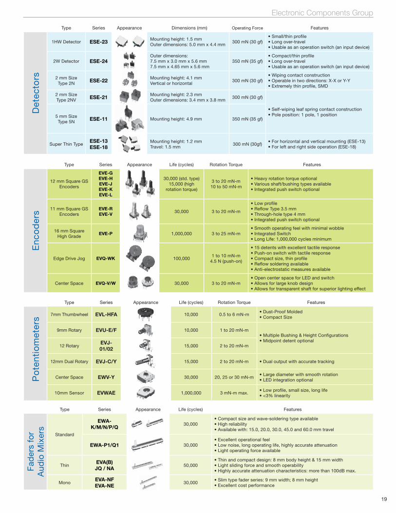
Type Series Appearance Life (cycles) Features
Fad
ers
for
Aud
io M
ixer
s
Standard
EWA-K/M/N/P/Q
30,000• Compact size and wave-soldering type available• High reliability• Available with: 15.0, 20.0, 30.0, 45.0 and 60.0 mm travel
EWA-P1/Q1 30,000• Excellent operational feel• Low noise, long operating life, highly accurate attenuation• Light operating force available
ThinEVA(B)JQ / NA
50,000• Thin and compact design: 8 mm body height & 15 mm width• Light sliding force and smooth operability• Highly accurate attenuation characteristics: more than 100dB max.
MonoEVA-NFEVA-NE
30,000• Slim type fader series: 9 mm width; 8 mm height• Excellent cost performance
Type Series Appearance Life (cycles) Rotation Torque Features
Enc
od
ers
12 mm Square GS Encoders
EVE-GEVE-HEVE-JEVE-KEVE-L
30,000 (std. type)15,000 (high
rotation torque)
3 to 20 mN-m10 to 50 mN-m
• Heavy rotation torque optional• Various shaft/bushing types available• Integrated push switch optional
11 mm Square GS Encoders
EVE-REVE-V 30,000 3 to 20 mN-m
• Low profile• Reflow Type 3.5 mm• Through-hole type 4 mm• Integrated push switch optional
16 mm SquareHigh Grade
EVE-P 1,000,000 3 to 25 mN-m• Smooth operating feel with minimal wobble• Integrated Switch• Long Life: 1,000,000 cycles minimum
Edge Drive Jog EVQ-WK 100,0001 to 10 mN-m
4.5 N (push-on)
• 15 detents with excellent tactile response• Push-on switch with tactile response• Compact size, thin profile• Reflow soldering available• Anti-electrostatic measures available
Center Space EVQ-V/W 30,000 3 to 20 mN-m• Open center space for LED and switch• Allows for large knob design• Allows for transparent shaft for superior lighting effect
Type Series Appearance Dimensions (mm) Operating Force Features
Det
ecto
rs1HW Detector ESE-23 Mounting height: 1.5 mm
Outer dimensions: 5.0 mm x 4.4 mm 300 mN (30 gf)
• Small/thin profile• Long over-travel• Usable as an operation switch (an input device)
2W Detector ESE-24Outer dimensions: 7.5 mm x 3.0 mm x 5.6 mm7.5 mm x 4.65 mm x 5.6 mm
350 mN (35 gf)• Compact/thin profile• Long over-travel• Usable as an operation switch (an input device)
2 mm SizeType 2N ESE-22 Mounting height: 4.1 mm
Vertical or horizontal300 mN (30 gf)
• Wiping contact construction• Operable in two directions: X-X or Y-Y• Extremely thin profile, SMD
2 mm SizeType 2NV ESE-21 Mounting height: 2.3 mm
Outer dimensions: 3.4 mm x 3.8 mm300 mN (30 gf)
• Self-wiping leaf spring contact construction• Pole position: 1 pole, 1 position5 mm Size
Type 5N ESE-11 Mounting height: 4.9 mm 350 mN (35 gf)
Super Thin TypeESE-13ESE-18
Mounting height: 1.2 mmTravel: 1.5 mm
300 mN (30gf)• For horizontal and vertical mounting (ESE-13)• For left and right side operation (ESE-18)
Po
tent
iom
eter
s
Type Series Appearance Life (cycles) Rotation Torque Features
7mm Thumbwheel EVL-HFA 10,000 0.5 to 6 mN-m• Dust-Proof Molded• Compact Size
9mm Rotary EVU-E/F 10,000 1 to 20 mN-m• Multiple Bushing & Height Configurations• Midpoint detent optional
12 RotaryEVJ-01/02
15,000 2 to 20 mN-m
12mm Dual Rotary EVJ-C/Y 15,000 2 to 20 mN-m • Dual output with accurate tracking
Center Space EWV-Y 30,000 20, 25 or 30 mN-m• Large diameter with smooth rotation• LED integration optional
10mm Sensor EVWAE 1,000,000 3 mN-m max.• Low profile, small size, long life• <3% linearity
Page 20
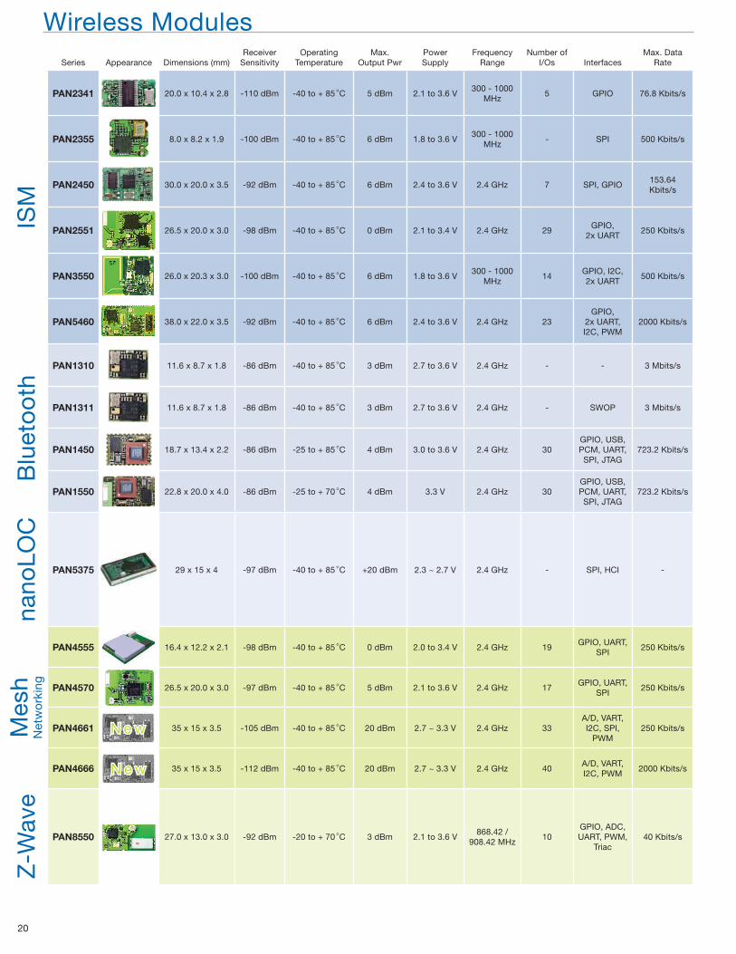
20
Wireless ModulesSeries Appearance Dimensions (mm)
ReceiverSensitivity
OperatingTemperature
Max.Output Pwr
PowerSupply
FrequencyRange
Number ofI/Os Interfaces
Max. DataRate
ISM
PAN2341 20.0 x 10.4 x 2.8 -110 dBm -40 to + 85dC 5 dBm 2.1 to 3.6 V300 - 1000
MHz5 GPIO 76.8 Kbits/s
PAN2355 8.0 x 8.2 x 1.9 -100 dBm -40 to + 85dC 6 dBm 1.8 to 3.6 V300 - 1000
MHz- SPI 500 Kbits/s
PAN2450 30.0 x 20.0 x 3.5 -92 dBm -40 to + 85dC 6 dBm 2.4 to 3.6 V 2.4 GHz 7 SPI, GPIO153.64 Kbits/s
PAN2551 26.5 x 20.0 x 3.0 -98 dBm -40 to + 85dC 0 dBm 2.1 to 3.4 V 2.4 GHz 29GPIO,
2x UART250 Kbits/s
PAN3550 26.0 x 20.3 x 3.0 -100 dBm -40 to + 85dC 6 dBm 1.8 to 3.6 V300 - 1000
MHz14
GPIO, I2C,2x UART
500 Kbits/s
PAN5460 38.0 x 22.0 x 3.5 -92 dBm -40 to + 85dC 6 dBm 2.4 to 3.6 V 2.4 GHz 23GPIO,
2x UART,I2C, PWM
2000 Kbits/s
Blu
eto
oth
PAN1310 11.6 x 8.7 x 1.8 -86 dBm -40 to + 85dC 3 dBm 2.7 to 3.6 V 2.4 GHz - - 3 Mbits/s
PAN1311 11.6 x 8.7 x 1.8 -86 dBm -40 to + 85dC 3 dBm 2.7 to 3.6 V 2.4 GHz - SWOP 3 Mbits/s
PAN1450 18.7 x 13.4 x 2.2 -86 dBm -25 to + 85dC 4 dBm 3.0 to 3.6 V 2.4 GHz 30GPIO, USB, PCM, UART, SPI, JTAG
723.2 Kbits/s
PAN1550 22.8 x 20.0 x 4.0 -86 dBm -25 to + 70dC 4 dBm 3.3 V 2.4 GHz 30GPIO, USB, PCM, UART, SPI, JTAG
723.2 Kbits/s
nano
LOC
PAN5375 29 x 15 x 4 -97 dBm -40 to + 85dC +20 dBm 2.3 ~ 2.7 V 2.4 GHz - SPI, HCI -
Mes
hN
etw
ork
ing
PAN4555 16.4 x 12.2 x 2.1 -98 dBm -40 to + 85dC 0 dBm 2.0 to 3.4 V 2.4 GHz 19GPIO, UART,
SPI250 Kbits/s
PAN4570 26.5 x 20.0 x 3.0 -97 dBm -40 to + 85dC 5 dBm 2.1 to 3.6 V 2.4 GHz 17GPIO, UART,
SPI250 Kbits/s
PAN4661 35 x 15 x 3.5 -105 dBm -40 to + 85dC 20 dBm 2.7 ~ 3.3 V 2.4 GHz 33A/D, VART, I2C, SPI,
PWM250 Kbits/s
PAN4666 35 x 15 x 3.5 -112 dBm -40 to + 85dC 20 dBm 2.7 ~ 3.3 V 2.4 GHz 40A/D, VART, I2C, PWM
2000 Kbits/s
Z-W
ave
PAN8550 27.0 x 13.0 x 3.0 -92 dBm -20 to + 70dC 3 dBm 2.1 to 3.6 V868.42 /
908.42 MHz10
GPIO, ADC, UART, PWM,
Triac40 Kbits/s
N e wN e w
N e wN e w
Page 21
Electronic Components Group
21
PAN2341 PAN2355 PAN2450
PAN2551 PAN3550 PAN5460
PAN1310/PAN1311 PAN1450 PAN1550
PAN5375 PAN4555 PAN4570
PAN8550
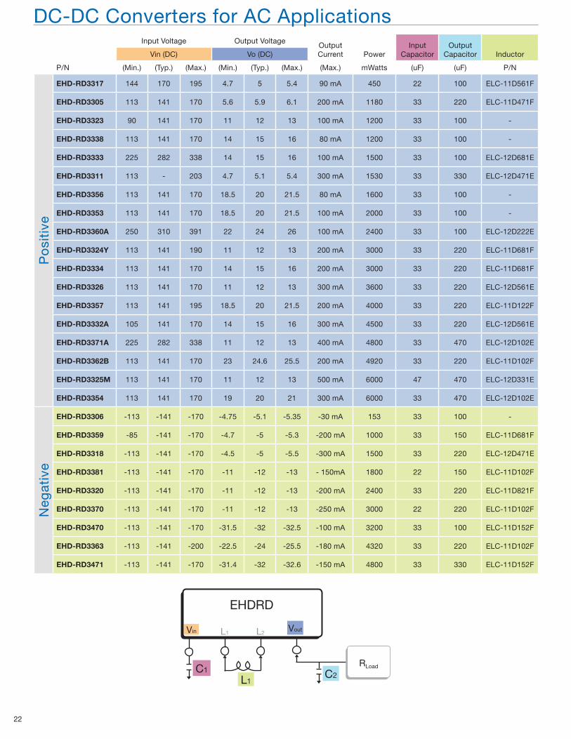
Page 22
22
P/N
Input Voltage Output VoltageOutput Current Power
Input Capacitor
Output Capacitor InductorVin (DC) Vo (DC)
(Min.) (Typ.) (Max.) (Min.) (Typ.) (Max.) (Max.) mWatts (uF) (uF) P/N
Po
siti
ve
EHD-RD3317 144 170 195 4.7 5 5.4 90 mA 450 22 100 ELC-11D561F
EHD-RD3305 113 141 170 5.6 5.9 6.1 200 mA 1180 33 220 ELC-11D471F
EHD-RD3323 90 141 170 11 12 13 100 mA 1200 33 100 -
EHD-RD3338 113 141 170 14 15 16 80 mA 1200 33 100 -
EHD-RD3333 225 282 338 14 15 16 100 mA 1500 33 100 ELC-12D681E
EHD-RD3311 113 - 203 4.7 5.1 5.4 300 mA 1530 33 330 ELC-12D471E
EHD-RD3356 113 141 170 18.5 20 21.5 80 mA 1600 33 100 -
EHD-RD3353 113 141 170 18.5 20 21.5 100 mA 2000 33 100 -
EHD-RD3360A 250 310 391 22 24 26 100 mA 2400 33 100 ELC-12D222E
EHD-RD3324Y 113 141 190 11 12 13 200 mA 3000 33 220 ELC-11D681F
EHD-RD3334 113 141 170 14 15 16 200 mA 3000 33 220 ELC-11D681F
EHD-RD3326 113 141 170 11 12 13 300 mA 3600 33 220 ELC-12D561E
EHD-RD3357 113 141 195 18.5 20 21.5 200 mA 4000 33 220 ELC-11D122F
EHD-RD3332A 105 141 170 14 15 16 300 mA 4500 33 220 ELC-12D561E
EHD-RD3371A 225 282 338 11 12 13 400 mA 4800 33 470 ELC-12D102E
EHD-RD3362B 113 141 170 23 24.6 25.5 200 mA 4920 33 220 ELC-11D102F
EHD-RD3325M 113 141 170 11 12 13 500 mA 6000 47 470 ELC-12D331E
EHD-RD3354 113 141 170 19 20 21 300 mA 6000 33 470 ELC-12D102E
Neg
ativ
e
EHD-RD3306 -113 -141 -170 -4.75 -5.1 -5.35 -30 mA 153 33 100 -
EHD-RD3359 -85 -141 -170 -4.7 -5 -5.3 -200 mA 1000 33 150 ELC-11D681F
EHD-RD3318 -113 -141 -170 -4.5 -5 -5.5 -300 mA 1500 33 220 ELC-12D471E
EHD-RD3381 -113 -141 -170 -11 -12 -13 - 150mA 1800 22 150 ELC-11D102F
EHD-RD3320 -113 -141 -170 -11 -12 -13 -200 mA 2400 33 220 ELC-11D821F
EHD-RD3370 -113 -141 -170 -11 -12 -13 -250 mA 3000 22 220 ELC-11D102F
EHD-RD3470 -113 -141 -170 -31.5 -32 -32.5 -100 mA 3200 33 100 ELC-11D152F
EHD-RD3363 -113 -141 -200 -22.5 -24 -25.5 -180 mA 4320 33 220 ELC-11D102F
EHD-RD3471 -113 -141 -170 -31.4 -32 -32.6 -150 mA 4800 33 330 ELC-11D152F
DC-DC Converters for AC Applications
EHDRD
RLoad
L1C2
Vin VoutL1 L2
C1
Page 23
Electronic Components Group
23
Page 24
Panasonic Industrial Company
SFC_0608Printed 06/08
Components Group3 Panasonic Way (7H-2)
Secaucus, NJ 070941-800-344-2112
http://www.panasonic.com/industrial/components


![[XLS] calculation 2006... · Web viewMaterialKits Components O&P fees Consult_Codes Replace AK, TK & HD cosmetic cover - Including consumable materials. Excludes components. Consultation](https://static.documents.pub/doc/80x56/5ae6276c7f8b9a29048d2ab6/xls-calculation-2006web-viewmaterialkits-components-op-fees-consultcodes-replace.jpg)


