Model No. KX-TDA0490 16-Channel VoIP Gateway Card Thank you for purchasing a Panasonic 16-Channel VoIP Gateway Card. Please read this manual carefully before using this product and save this manual for future use. Programming Guide www.voicesonic.com Phone: 877-289-2829 Panasonic Telephone Systems Panasonic KX-TDA0490, KXTDA0490, TDA0490
Transcript
Model No. KX-TDA0490
16-Channel VoIP Gateway Card
Thank you for purchasing a Panasonic 16-Channel VoIP Gateway Card.Please read this manual carefully before using this product and save this manual for future use.
Table of Contents1 IP-GW16 Maintenance Utility ................................................................. 31.1 Starting the IP-GW16 Maintenance Utility.......................................................................4
2 Administrator Functions........................................................................72.1 Main Menu for the Administrator.....................................................................................82.2 Programming...................................................................................................................102.2.1 Network Parameters .........................................................................................................102.2.2 H.323 Parameters .............................................................................................................142.2.3 Voice Communication Parameters....................................................................................182.2.4 VoIP Gateway/IP-PBX Interface Parameters ....................................................................262.2.5 Hunt Pattern Parameters ..................................................................................................282.2.6 Address Translation Table—GW Entry .............................................................................342.2.7 Address Translation Table—DN2IP Entry .........................................................................372.2.8 Initialization .......................................................................................................................412.3 Maintenance ....................................................................................................................422.3.1 Status Control....................................................................................................................422.3.2 Maintenance Settings .......................................................................................................432.3.3 Diagnosis ..........................................................................................................................462.3.4 Log Information .................................................................................................................472.4 Data Management ...........................................................................................................482.4.1 Upload of Configuration Data............................................................................................482.4.2 Download of Configuration Data .......................................................................................502.4.3 Upload of Address Translation Table ................................................................................512.4.4 Download of Address Translation Table............................................................................532.5 Others ..............................................................................................................................542.5.1 Reboot ..............................................................................................................................542.5.2 Log Out .............................................................................................................................55
3 Installer Functions................................................................................ 573.1 Main Menu for the Installer.............................................................................................583.2 Maintenance ....................................................................................................................593.2.1 Status Control....................................................................................................................593.2.2 Maintenance Settings .......................................................................................................603.3 Data Management ...........................................................................................................623.3.1 Upload of Firmware Data ..................................................................................................623.3.2 Handling of Firmware Page...............................................................................................653.4 Others ..............................................................................................................................673.4.1 Reboot ..............................................................................................................................673.4.2 Log Out .............................................................................................................................68
Index ............................................................................................................ 69
2 Programming Guide
Section 1
IP-GW16 Maintenance Utility
Programming of the VoIP Gateway Card is carried out through a web programming utility called the IP-GW16 Maintenance Utility. This section provides the start-up procedure for the IP-GW16 Maintenance Utility.
Programming Guide 3
1.1 Starting the IP-GW16 Maintenance Utility
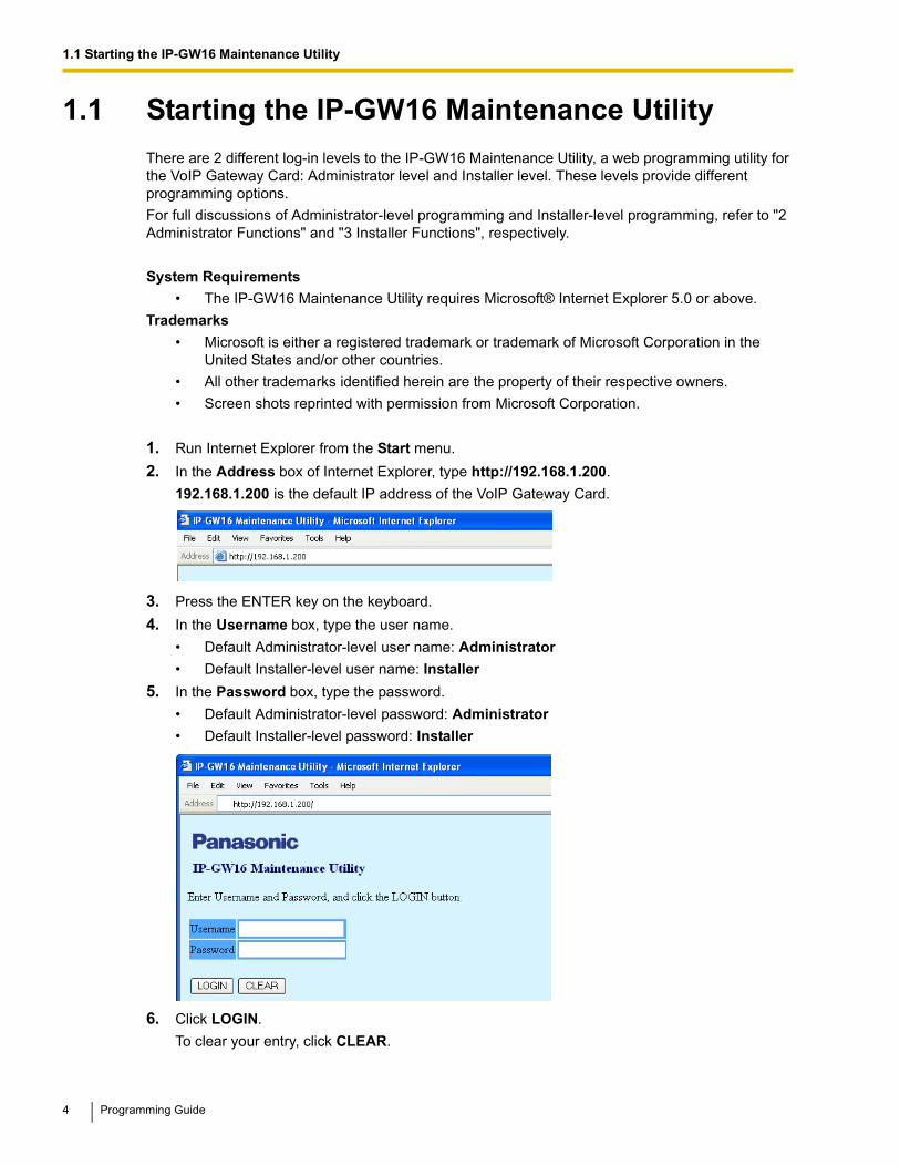
1.1 Starting the IP-GW16 Maintenance UtilityThere are 2 different log-in levels to the IP-GW16 Maintenance Utility, a web programming utility for the VoIP Gateway Card: Administrator level and Installer level. These levels provide different programming options.
For full discussions of Administrator-level programming and Installer-level programming, refer to "2 Administrator Functions" and "3 Installer Functions", respectively.
System Requirements• The IP-GW16 Maintenance Utility requires Microsoft® Internet Explorer 5.0 or above.
Trademarks
• Microsoft is either a registered trademark or trademark of Microsoft Corporation in the United States and/or other countries.
• All other trademarks identified herein are the property of their respective owners.
• Screen shots reprinted with permission from Microsoft Corporation.
1. Run Internet Explorer from the Start menu.
2. In the Address box of Internet Explorer, type http://192.168.1.200.
192.168.1.200 is the default IP address of the VoIP Gateway Card.
3. Press the ENTER key on the keyboard.
4. In the Username box, type the user name.
• Default Administrator-level user name: Administrator
• If another user is already logged in, you will be rejected.
• For readability of the text on the screen, it is recommended that you adjust the text size of Internet Explorer to below medium.
• If you finish a programming session without logging out from the card (e.g., quitting Internet Explorer, or returning to the log-in screen with the "Back" button of Internet Explorer), you cannot log in again for the period of time specified by the parameter Programming Auto Disconnect Time (default: 10 min).For the log-out procedure and Programming Auto Disconnect Time setting, refer to "2.5.2 Log Out"/"3.4.2 Log Out" and "2.3.2 Maintenance Settings", respectively.
Programming Guide 5
1.1 Starting the IP-GW16 Maintenance Utility
6 Programming Guide
Section 2
Administrator Functions
This section provides operating instructions for the IP-GW16 Maintenance Utility when logged in as the Administrator.
Programming Guide 7
2.1 Main Menu for the Administrator
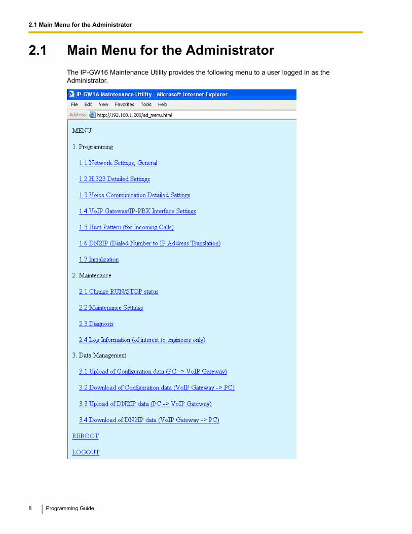
2.1 Main Menu for the AdministratorThe IP-GW16 Maintenance Utility provides the following menu to a user logged in as the Administrator.
8 Programming Guide
2.1 Main Menu for the Administrator
Programming
Maintenance
Data Management
Others
Menu Section Reference
1.1 Network Settings, General 2.2.1 Network Parameters
3.1 Upload of Configuration data (PC → VoIP Gateway)
2.4.1 Upload of Configuration Data
3.2 Download of Configuration data (VoIP Gateway → PC)
2.4.2 Download of Configuration Data
3.3 Upload of DN2IP data (PC → VoIP Gateway)
2.4.3 Upload of Address Translation Table
3.4 Download of DN2IP data (VoIP Gateway → PC)
2.4.4 Download of Address Translation Table
Menu Section Reference
REBOOT 2.5.1 Reboot
LOGOUT 2.5.2 Log Out
Programming Guide 9
2.2 Programming
2.2 Programming
2.2.1 Network Parameters
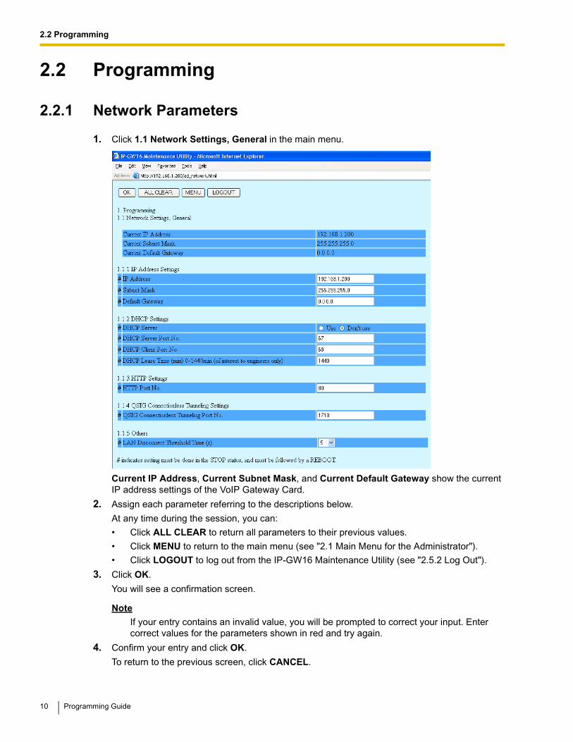
1. Click 1.1 Network Settings, General in the main menu.
Current IP Address, Current Subnet Mask, and Current Default Gateway show the current IP address settings of the VoIP Gateway Card.
2. Assign each parameter referring to the descriptions below.
At any time during the session, you can:
• Click ALL CLEAR to return all parameters to their previous values.
• Click MENU to return to the main menu (see "2.1 Main Menu for the Administrator").
• Click LOGOUT to log out from the IP-GW16 Maintenance Utility (see "2.5.2 Log Out").
3. Click OK.
You will see a confirmation screen.
NoteIf your entry contains an invalid value, you will be prompted to correct your input. Enter correct values for the parameters shown in red and try again.
4. Confirm your entry and click OK.
To return to the previous screen, click CANCEL.
10 Programming Guide
2.2 Programming
Parameter DescriptionsThe parameters indicated with "#" must be changed while the card is in the "STOP" status (see "2.3.1 Status Control"). The changes must be followed by a reboot to become effective (see "2.5.1 Reboot").
IP Address Settings
DHCP Settings
Parameter & Description Default Value Range
# IP AddressSpecifies the IP address of the card.
For more information, consult your network administrator.
192.168.1.200 The following addresses are invalid:
• Class D addresses
• Class E addresses
• Loopback addresses
• Addresses with host number all 0s or 1s
# Subnet MaskSpecifies the subnet mask address of the card.
For more information, consult your network administrator.
255.255.255.0 Any address is valid.
# Default GatewaySpecifies the default gateway IP address of the card.
For more information, consult your network administrator.
0.0.0.0 Same as the parameter IP Address, except that the address 0.0.0.0. is allowed.
Parameter & Description Default Value Range
# DHCP ServerSpecifies the use of a DHCP server.
For details, refer to "Detailed Explanations".
Don't use Use,Don't use
# DHCP Server Port No.Specifies the port number for DHCP communications by the DHCP server.
Generally, there is no need to change the default value.
67 1 to 65535
# DHCP Client Port No.Specifies the port number for DHCP communications by the card (the DHCP client).
Generally, there is no need to change the default value.
68 1 to 65535
# DHCP Lease Time (min) 1-1440minThis parameter is provided for engineer use only.
1440 0 (disable),1 to 1440
Programming Guide 11
2.2 Programming
HTTP Settings
QSIG Connectionless Tunneling Settings
Others
Detailed Explanations
DHCP ServerWhen using the DHCP feature, the IP address settings of the card (IP address, subnet mask, and default gateway) will be assigned by a DHCP server.
However, keep in mind that the maintenance of the card is performed through a web browser from a PC; hence you must know the IP address of the card. Therefore, it is necessary to set up the DHCP
Parameter & Description Default Value Range
# HTTP Port No.Specifies the port number for HTTP communications by the card.
Generally, there is no need to change the default value.
80 1 to 65535
Parameter & Description Default Value Range
# QSIG Connectionless Tunneling Port No.Specifies the port number for connectionless tunneling between cards at different locations in a QSIG network.
Generally, there is no need to change the default value.
Notes
• Connectionless tunneling enables the PBXs on a QSIG network to use enhanced networking features. (For more information about these features, refer to the relevant sections of the Hybrid IP-PBX documentation.)
• If you are using a gatekeeper, and "Routed" is specified for the parameter Call Signaling Model (see "2.2.2 H.323 Parameters"), connectionless tunneling is not possible. In this case, the PBX cannot use the enhanced networking features.
1718 1 to 65535
Parameter & Description Default Value Range
# LAN Disconnect Threshold Time (s)Specifies the time (in seconds) until disconnection from the LAN is recognized.
For example, even if a LAN cable is disconnected during a call, reconnecting the cable within this time period maintains the call.
5 1 to 10
12 Programming Guide
2.2 Programming
server to assign a static IP address to the card from a pool of IP addresses that is defined in advance. For more information about DHCP server settings, consult your network administrator.
In addition, it is also necessary to specify the values for the parameters under IP Address Settings as they will be assigned by the DHCP server.
Programming Guide 13
2.2 Programming
2.2.2 H.323 Parameters
1. Click 1.2 H.323 Detailed Settings in the main menu.
2. Assign each parameter referring to the descriptions below.
At any time during the session, you can:
• Click ALL CLEAR to return all parameters to their previous values.
• Click MENU to return to the main menu (see "2.1 Main Menu for the Administrator").
• Click LOGOUT to log out from the IP-GW16 Maintenance Utility (see "2.5.2 Log Out").
3. Click OK.
You will see a confirmation screen.
Note
If your entry contains an invalid value, you will be prompted to correct your input. Enter correct values for the parameters shown in red and try again.
4. Confirm your entry and click OK.
To return to the previous screen, click CANCEL.
14 Programming Guide
2.2 Programming
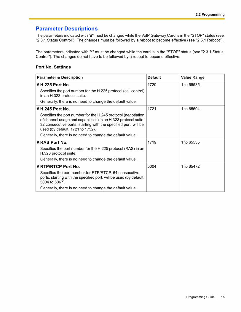
Parameter DescriptionsThe parameters indicated with "#" must be changed while the VoIP Gateway Card is in the "STOP" status (see "2.3.1 Status Control"). The changes must be followed by a reboot to become effective (see "2.5.1 Reboot").
The parameters indicated with "*" must be changed while the card is in the "STOP" status (see "2.3.1 Status Control"). The changes do not have to be followed by a reboot to become effective.
Port No. Settings
Parameter & Description Default Value Range
# H.225 Port No.Specifies the port number for the H.225 protocol (call control) in an H.323 protocol suite.
Generally, there is no need to change the default value.
1720 1 to 65535
# H.245 Port No.Specifies the port number for the H.245 protocol (negotiation of channel usage and capabilities) in an H.323 protocol suite. 32 consecutive ports, starting with the specified port, will be used (by default, 1721 to 1752).
Generally, there is no need to change the default value.
1721 1 to 65504
# RAS Port No.Specifies the port number for the H.225 protocol (RAS) in an H.323 protocol suite.
Generally, there is no need to change the default value.
1719 1 to 65535
# RTP/RTCP Port No.Specifies the port number for RTP/RTCP. 64 consecutive ports, starting with the specified port, will be used (by default, 5004 to 5067).
Generally, there is no need to change the default value.
5004 1 to 65472
Programming Guide 15
2.2 Programming
Voice CODEC Settings
Gatekeeper Settings
Parameter & Description Default Value Range
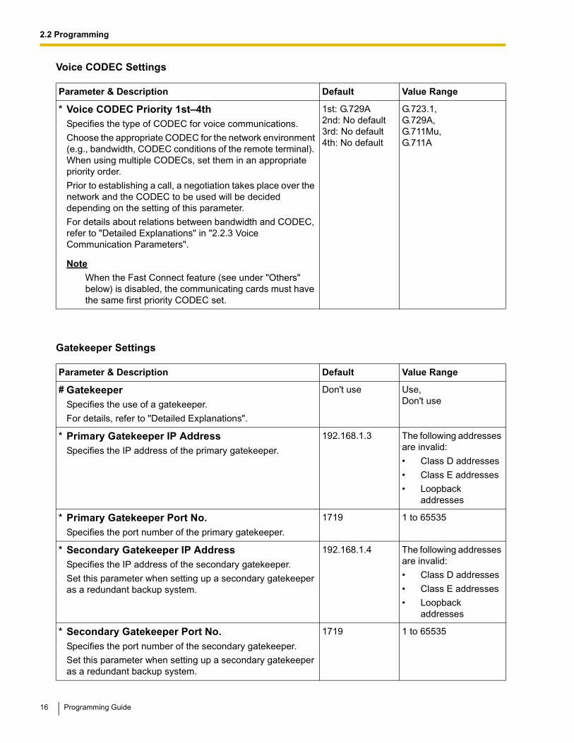
* Voice CODEC Priority 1st–4thSpecifies the type of CODEC for voice communications.
Choose the appropriate CODEC for the network environment (e.g., bandwidth, CODEC conditions of the remote terminal). When using multiple CODECs, set them in an appropriate priority order.
Prior to establishing a call, a negotiation takes place over the network and the CODEC to be used will be decided depending on the setting of this parameter.
For details about relations between bandwidth and CODEC, refer to "Detailed Explanations" in "2.2.3 Voice Communication Parameters".
Note
When the Fast Connect feature (see under "Others" below) is disabled, the communicating cards must have the same first priority CODEC set.
1st: G.729A2nd: No default3rd: No default4th: No default
G.723.1,G.729A,G.711Mu,G.711A
Parameter & Description Default Value Range
# GatekeeperSpecifies the use of a gatekeeper.
For details, refer to "Detailed Explanations".
Don't use Use,Don't use
* Primary Gatekeeper IP AddressSpecifies the IP address of the primary gatekeeper.
192.168.1.3 The following addresses are invalid:
• Class D addresses
• Class E addresses
• Loopback addresses
* Primary Gatekeeper Port No.Specifies the port number of the primary gatekeeper.
1719 1 to 65535
* Secondary Gatekeeper IP AddressSpecifies the IP address of the secondary gatekeeper.
Set this parameter when setting up a secondary gatekeeper as a redundant backup system.
192.168.1.4 The following addresses are invalid:
• Class D addresses
• Class E addresses
• Loopback addresses
* Secondary Gatekeeper Port No.Specifies the port number of the secondary gatekeeper.
Set this parameter when setting up a secondary gatekeeper as a redundant backup system.
1719 1 to 65535
16 Programming Guide
2.2 Programming
Others
Detailed Explanations
GatekeeperThe following are the general functions of a gatekeeper:
• Dialed number-to-IP address translation
• Authentication
• Bandwidth control
It is possible to employ a VoIP network without the use of a gatekeeper, because the card is equipped with internal address translation capabilities. However, should the network contain dozens of cards, maintenance of address translation tables in individual cards can become a strain.
A gatekeeper is useful in this case, because with the gatekeeper it is possible to consolidate the maintenance. (However, you still need to program each card on the network with its own address translation information. For details, refer to "2.2.6 Address Translation Table—GW Entry" and "2.2.7 Address Translation Table—DN2IP Entry".) For more information about gatekeeper functions, consult the documentation of the gatekeeper.
When using a gatekeeper, make sure to choose a compatible model. For more information about gatekeeper compatibility with the card, consult a certified dealer.
* Gatekeeper Connection Checking Interval (min) 0-1440minSpecifies the time (in minutes) between periodic checks of connection to the gatekeeper.
When the primary gatekeeper fails, these checks can detect the failure. In this case, the connection automatically switches to the secondary gatekeeper if it is available, so that the network remains functional.
0 0 (disable),1 to 1440
* Call Signaling ModelSpecifies whether to carry out a call control (H.225) process directly between the cards or through a gatekeeper.
Direct call control is typically preferred because it involves less network load.
Direct Direct,Routed (via Gatekeeper)
Parameter & Description Default Value Range
# Fast ConnectSpecifies the use of the Fast Connect feature.
Using Fast Connect simplifies the communication process so that calls can be established quickly.
Generally, there is no need to change the default value.
Use Use,Don't use
Parameter & Description Default Value Range
Programming Guide 17
2.2 Programming
2.2.3 Voice Communication Parameters
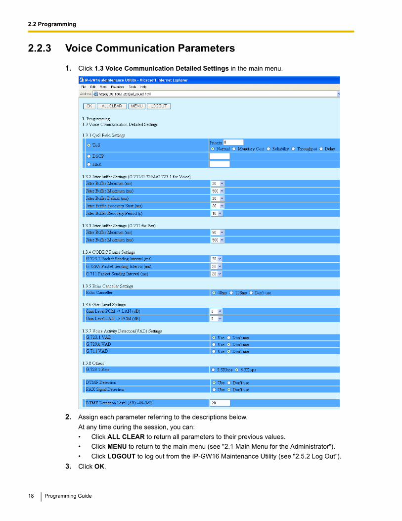
1. Click 1.3 Voice Communication Detailed Settings in the main menu.
2. Assign each parameter referring to the descriptions below.
At any time during the session, you can:
• Click ALL CLEAR to return all parameters to their previous values.
• Click MENU to return to the main menu (see "2.1 Main Menu for the Administrator").
• Click LOGOUT to log out from the IP-GW16 Maintenance Utility (see "2.5.2 Log Out").
3. Click OK.
18 Programming Guide
2.2 Programming
You will see a confirmation screen.
Note
If your entry contains an invalid value, you will be prompted to correct your input. Enter correct values for the parameters shown in red and try again.
4. Confirm your entry and click OK.
To return to the previous screen, click CANCEL.
Parameter Descriptions
QoS Field SettingsThe parameters below are used to set the ToS (Type of Service) field in the header of IP packets to control QoS of VoIP communications.
For more information about QoS, refer to "A1.4 QoS (Quality of Service)" of the VoIP Gateway Card Getting Started. For the actual setting values, consult your network administrator.
Jitter Buffer SettingsWhen voice signals are packetized and transmitted, individual packets can take different paths through the network and arrive at the destination at varied timings. This is referred to as "jitter", and it can cause degradation in speech quality. To compensate for jitter problems, the "jitter buffer" accumulates the packets temporarily for processing.
The parameters below are used to adjust the size of the jitter buffer. However, in general, there is no need to change the default values.
Jitter buffer Settings (G.711/G.729A/G.723.1 for Voice)
Parameter & Description Default Value Range
ToSSpecifies the value in the ToS field by a generic term.
For details, refer to "Detailed Explanations".
Priority: 0 0 to 7
Normal Normal,Monetary Cost,Reliability,Throughput,Delay
DSCPSpecifies the value in the ToS field by a DSCP for DiffServ.
No default 0 to 63
HEXSpecifies the value in the ToS field by a hexadecimal number.
CODEC Frame SettingsThe parameters below are used to set the interval between packet transmissions for each type of CODEC. It is recommended that all VoIP Gateway Cards in a VoIP network have the same settings for these parameters.
Echo CancellerSpecifies the length of the echo canceller (in milliseconds) when using the echo cancellation feature (G.168), or disables the feature.
Echo is the audible duplication of a caller's voice on the return path; when echo exists, the caller hears his or her own voice after some delay. The echo canceller eliminates this echo.
Generally, the default length of 48 ms will suffice. However, if an echo is still heard, it is recommended that you set the length to 128 ms.
NoteThere are various factors that may cause an echo. In some cases, this feature does not eliminate the echo entirely.
48 48, 128, Don't use
20 Programming Guide
2.2 Programming
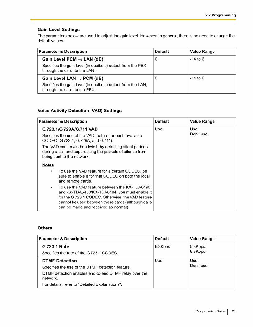
Gain Level SettingsThe parameters below are used to adjust the gain level. However, in general, there is no need to change the default values.
Voice Activity Detection (VAD) Settings
Others
Parameter & Description Default Value Range
Gain Level PCM → LAN (dB)Specifies the gain level (in decibels) output from the PBX, through the card, to the LAN.
0 -14 to 6
Gain Level LAN → PCM (dB)Specifies the gain level (in decibels) output from the LAN, through the card, to the PBX.
0 -14 to 6
Parameter & Description Default Value Range
G.723.1/G.729A/G.711 VADSpecifies the use of the VAD feature for each available CODEC (G.723.1, G.729A, and G.711).
The VAD conserves bandwidth by detecting silent periods during a call and suppressing the packets of silence from being sent to the network.
Notes
• To use the VAD feature for a certain CODEC, be sure to enable it for that CODEC on both the local and remote cards.
• To use the VAD feature between the KX-TDA0490 and KX-TDA5480/KX-TDA0484, you must enable it for the G.723.1 CODEC. Otherwise, the VAD feature cannot be used between these cards (although calls can be made and received as normal).
Use Use,Don't use
Parameter & Description Default Value Range
G.723.1 RateSpecifies the rate of the G.723.1 CODEC.
6.3Kbps 5.3Kbps,6.3Kbps
DTMF Detection Specifies the use of the DTMF detection feature.
DTMF detection enables end-to-end DTMF relay over the network.
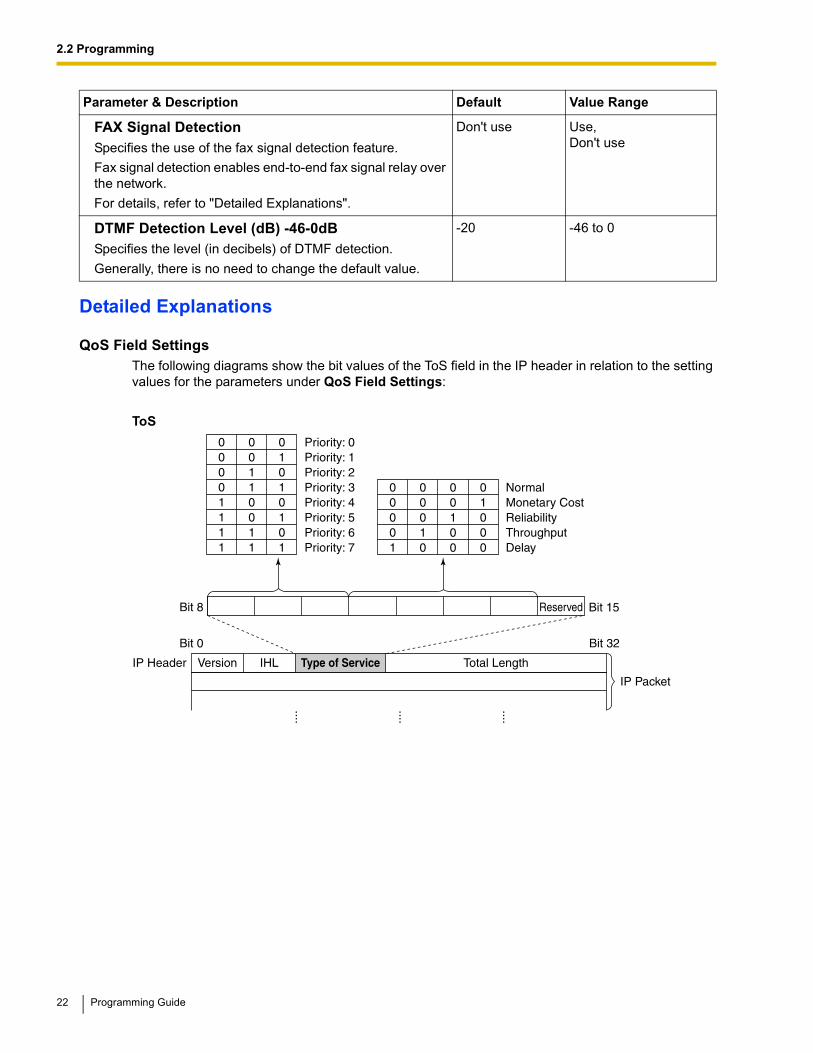
QoS Field SettingsThe following diagrams show the bit values of the ToS field in the IP header in relation to the setting values for the parameters under QoS Field Settings:
ToS
FAX Signal DetectionSpecifies the use of the fax signal detection feature.
Fax signal detection enables end-to-end fax signal relay over the network.
For details, refer to "Detailed Explanations".
Don't use Use,Don't use
DTMF Detection Level (dB) -46-0dBSpecifies the level (in decibels) of DTMF detection.
Generally, there is no need to change the default value.
CODEC Frame SettingsThe amount of required bandwidth depends on the type of CODEC and the selected packet sending interval. The tables below show the amount of bandwidth required for one VoIP channel in each case:
Required Bandwidth for Voice Communication via LAN
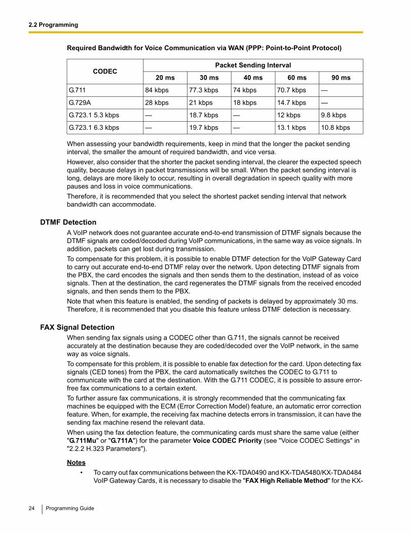
Required Bandwidth for Voice Communication via WAN (PPP: Point-to-Point Protocol)
When assessing your bandwidth requirements, keep in mind that the longer the packet sending interval, the smaller the amount of required bandwidth, and vice versa.
However, also consider that the shorter the packet sending interval, the clearer the expected speech quality, because delays in packet transmissions will be small. When the packet sending interval is long, delays are more likely to occur, resulting in overall degradation in speech quality with more pauses and loss in voice communications.
Therefore, it is recommended that you select the shortest packet sending interval that network bandwidth can accommodate.
DTMF DetectionA VoIP network does not guarantee accurate end-to-end transmission of DTMF signals because the DTMF signals are coded/decoded during VoIP communications, in the same way as voice signals. In addition, packets can get lost during transmission.
To compensate for this problem, it is possible to enable DTMF detection for the VoIP Gateway Card to carry out accurate end-to-end DTMF relay over the network. Upon detecting DTMF signals from the PBX, the card encodes the signals and then sends them to the destination, instead of as voice signals. Then at the destination, the card regenerates the DTMF signals from the received encoded signals, and then sends them to the PBX.
Note that when this feature is enabled, the sending of packets is delayed by approximately 30 ms. Therefore, it is recommended that you disable this feature unless DTMF detection is necessary.
FAX Signal DetectionWhen sending fax signals using a CODEC other than G.711, the signals cannot be received accurately at the destination because they are coded/decoded over the VoIP network, in the same way as voice signals.
To compensate for this problem, it is possible to enable fax detection for the card. Upon detecting fax signals (CED tones) from the PBX, the card automatically switches the CODEC to G.711 to communicate with the card at the destination. With the G.711 CODEC, it is possible to assure error-free fax communications to a certain extent.
To further assure fax communications, it is strongly recommended that the communicating fax machines be equipped with the ECM (Error Correction Model) feature, an automatic error correction feature. When, for example, the receiving fax machine detects errors in transmission, it can have the sending fax machine resend the relevant data.
When using the fax detection feature, the communicating cards must share the same value (either "G.711Mu" or "G.711A") for the parameter Voice CODEC Priority (see "Voice CODEC Settings" in "2.2.2 H.323 Parameters").
Notes
• To carry out fax communications between the KX-TDA0490 and KX-TDA5480/KX-TDA0484 VoIP Gateway Cards, it is necessary to disable the "FAX High Reliable Method" for the KX-
1. Click 1.4 VoIP Gateway/IP-PBX Interface Settings in the main menu.
2. Assign each parameter referring to the descriptions below.
At any time during the session, you can:
• Click ALL CLEAR to return all parameters to their previous values.
• Click MENU to return to the main menu (see "2.1 Main Menu for the Administrator").
• Click LOGOUT to log out from the IP-GW16 Maintenance Utility (see "2.5.2 Log Out").
3. Click OK.
You will see a confirmation screen.
NoteIf your entry contains an invalid value, you will be prompted to correct your input. Enter correct values for the parameters shown in red and try again.
4. Confirm your entry and click OK.
To return to the previous screen, click CANCEL.
Parameter DescriptionsThe parameters indicated with "*" must be changed while the VoIP Gateway Card is in the "STOP" status (see "2.3.1 Status Control"). The changes do not have to be followed by a reboot to become effective.
Dialing Settings
Parameter & Description Default Value Range
* First Digit Time (s) 5-30sSpecifies the length of time (in seconds) within which the first digit of a dial number must be dialed after seizing a VoIP gateway trunk (CO line).
Generally, there is no need to change the default value.
20 5 to 30
* Inter-Digit Time (s) 1-10sSpecifies the length of time (in seconds) within which subsequent digits of a dial number must be dialed.
Generally, there is no need to change the default value.
5 1 to 10
26 Programming Guide
2.2 Programming
Others
* Digit End CodeSpecifies the delimiter code to be used to signal the end of a dial number.
Generally, there is no need to change the default value.
# 0 to 9, #, *
Parameter & Description Default Value Range
Network CODEC of IP-PBXThe value of this parameter is set automatically as appropriate to the setting of the PBX.
There is no need to change the value.
Not applicable G.711 Mu-Law,G.711 A-Law
Parameter & Description Default Value Range
Programming Guide 27
2.2 Programming
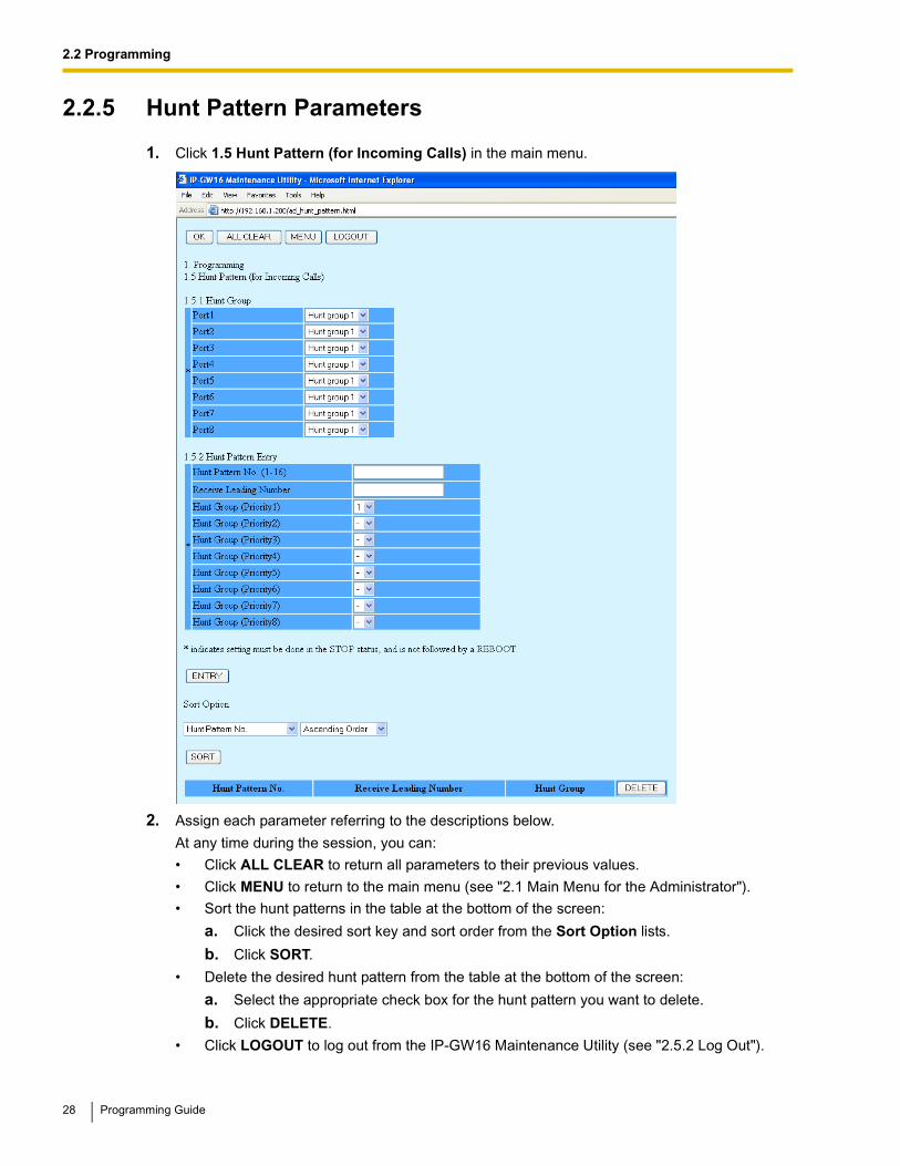
2.2.5 Hunt Pattern Parameters
1. Click 1.5 Hunt Pattern (for Incoming Calls) in the main menu.
2. Assign each parameter referring to the descriptions below.
At any time during the session, you can:
• Click ALL CLEAR to return all parameters to their previous values.
• Click MENU to return to the main menu (see "2.1 Main Menu for the Administrator").
• Sort the hunt patterns in the table at the bottom of the screen:
a. Click the desired sort key and sort order from the Sort Option lists.
b. Click SORT.
• Delete the desired hunt pattern from the table at the bottom of the screen:
a. Select the appropriate check box for the hunt pattern you want to delete.
b. Click DELETE.
• Click LOGOUT to log out from the IP-GW16 Maintenance Utility (see "2.5.2 Log Out").
28 Programming Guide
2.2 Programming
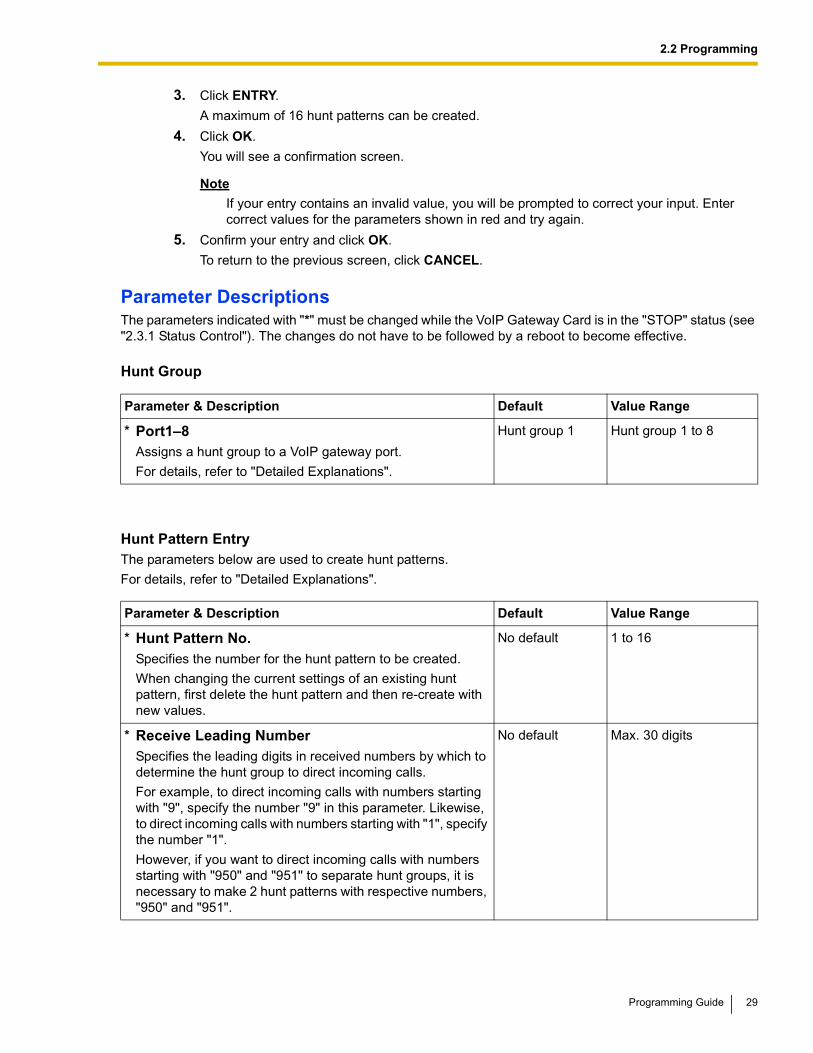
3. Click ENTRY.
A maximum of 16 hunt patterns can be created.
4. Click OK.
You will see a confirmation screen.
NoteIf your entry contains an invalid value, you will be prompted to correct your input. Enter correct values for the parameters shown in red and try again.
5. Confirm your entry and click OK.
To return to the previous screen, click CANCEL.
Parameter DescriptionsThe parameters indicated with "*" must be changed while the VoIP Gateway Card is in the "STOP" status (see "2.3.1 Status Control"). The changes do not have to be followed by a reboot to become effective.
Hunt Group
Hunt Pattern EntryThe parameters below are used to create hunt patterns.
For details, refer to "Detailed Explanations".
Parameter & Description Default Value Range
* Port1–8Assigns a hunt group to a VoIP gateway port.
For details, refer to "Detailed Explanations".
Hunt group 1 Hunt group 1 to 8
Parameter & Description Default Value Range
* Hunt Pattern No.Specifies the number for the hunt pattern to be created.
When changing the current settings of an existing hunt pattern, first delete the hunt pattern and then re-create with new values.
No default 1 to 16
* Receive Leading NumberSpecifies the leading digits in received numbers by which to determine the hunt group to direct incoming calls.
For example, to direct incoming calls with numbers starting with "9", specify the number "9" in this parameter. Likewise, to direct incoming calls with numbers starting with "1", specify the number "1".
However, if you want to direct incoming calls with numbers starting with "950" and "951" to separate hunt groups, it is necessary to make 2 hunt patterns with respective numbers, "950" and "951".
No default Max. 30 digits
Programming Guide 29
2.2 Programming
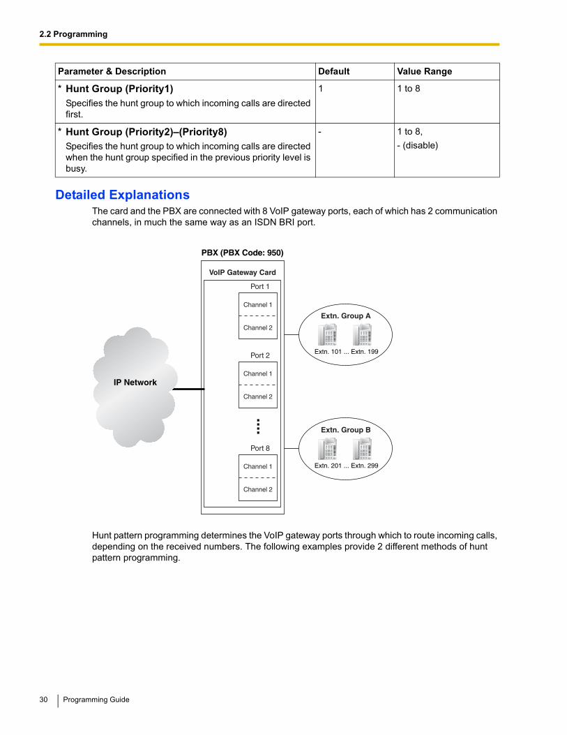
Detailed ExplanationsThe card and the PBX are connected with 8 VoIP gateway ports, each of which has 2 communication channels, in much the same way as an ISDN BRI port.
Hunt pattern programming determines the VoIP gateway ports through which to route incoming calls, depending on the received numbers. The following examples provide 2 different methods of hunt pattern programming.
* Hunt Group (Priority1)Specifies the hunt group to which incoming calls are directed first.
1 1 to 8
* Hunt Group (Priority2)–(Priority8)Specifies the hunt group to which incoming calls are directed when the hunt group specified in the previous priority level is busy.
- 1 to 8,
- (disable)
Parameter & Description Default Value Range
IP Network
VoIP Gateway Card
Port 1
PBX (PBX Code: 950)
Extn. Group A
Extn. 101 ... Extn. 199
Channel 1
Channel 2
Extn. Group B
Extn. 201 ... Extn. 299
Port 2
Channel 1
Channel 2
....
Port 8
Channel 1
Channel 2
30 Programming Guide
2.2 Programming
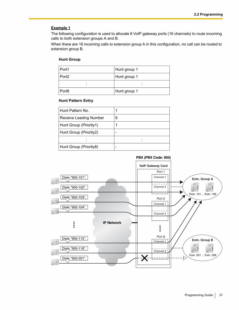
Example 1
The following configuration is used to allocate 8 VoIP gateway ports (16 channels) to route incoming calls to both extension groups A and B.
When there are 16 incoming calls to extension group A in this configuration, no call can be routed to extension group B.
Hunt Group
Hunt Pattern Entry
Port1 Hunt group 1
Port2 Hunt group 1
: :
Port8 Hunt group 1
Hunt Pattern No. 1
Receive Leading Number 9
Hunt Group (Priority1) 1
Hunt Group (Priority2) -
: :
Hunt Group (Priority8) -
IP Network
Extn. Group A
Extn. 101 ... Extn. 199
Extn. Group B
Extn. 201 ... Extn. 299
Dials "950-101".
Dials "950-102".
Dials "950-103".
Dials "950-104".
VoIP Gateway Card
Port 1
PBX (PBX Code: 950)
Channel 1
Channel 2
Port 2
Channel 1
Channel 2
Port 8
Channel 1
Channel 2
Dials "950-115".
Dials "950-116".
Dials "950-201".
....
....
Programming Guide 31
2.2 Programming
Example 2
The following configuration is used to divide 8 VoIP gateway ports (16 channels) into 2 groups of 4, and then allocate each group to individual extension groups. Specifically, with this configuration, calls to extension group A are routed through the first group of ports (consisting of ports 1 to 4). Likewise, calls to extension group B are routed through the second group of ports (consisting of ports 5 to 8).
When all 8 channels in the first group of ports are being used, this configuration rejects the 9th call to extension group A. However, the other 8 channels in the second group of ports remain available to route calls to extension group B.
Hunt Group
Hunt Pattern Entry—1
Hunt Pattern Entry—2
Port1 Hunt group 1
: :
Port4 Hunt group 1
Port5 Hunt group 2
: :
Port8 Hunt group 2
Hunt Pattern No. 1
Receive Leading Number 9501
Hunt Group (Priority1) 1
Hunt Group (Priority2) -
: :
Hunt Group (Priority8) -
Hunt Pattern No. 2
Receive Leading Number 9502
Hunt Group (Priority1) 2
Hunt Group (Priority2) -
: :
Hunt Group (Priority8) -
32 Programming Guide
2.2 Programming
It is possible to program the PBX to allocate separate groups of VoIP gateway ports to individual extension groups A and B for making outgoing calls. With this programming, each extension group, A and B, can have a group of ports for its exclusive use.
For example:
• The VoIP gateway ports that extension group A uses to make outgoing calls: ports 1 to 4
• The VoIP gateway ports that extension group B uses to make outgoing calls: ports 5 to 8
Note
The example above details the configuration to route incoming calls to 2 separate hunt groups, each of which is associated with an individual extension group. However, note that various other types of configurations are possible. For example, it is possible to route calls to 8 separate hunt groups, so that you can distribute the calls to 8 different extension groups.
IP Network
Extn. Group A
Extn. 101 ... Extn. 199
Dials "950-101".
Dials "950-102".
VoIP Gateway Card
PBX (PBX Code: 950)
Port 1
Channel 1
Channel 2
Extn. Group B
Extn. 201 ... Extn. 299
Port 4
Channel 1
Channel 2
Dials "950-107".
Dials "950-108".
Dials "950-109".
....
....
Dials "950-201".
Dials "950-202".
Port 5
Channel 1
Channel 2
Port 8
Channel 1
Channel 2
Dials "950-207".
Dials "950-208".
....
....
Programming Guide 33
2.2 Programming
2.2.6 Address Translation Table—GW Entry
1. Click 1.6 DN2IP (Dialed Number to IP Address Translation) in the main menu.
2. Click 1.6.1 GW Entry.
3. Assign each parameter referring to the descriptions below.
At any time during the session, you can:
• Click MENU to return to the main menu (see "2.1 Main Menu for the Administrator").
• Click PREVIOUS to return to the previous screen.
• Sort the gateway entries in the table at the bottom of the screen:
a. Click the desired sort key and sort order from the Sort Option lists.
b. Click SORT.
• Delete the desired gateway entry from the table at the bottom of the screen:
a. Select the appropriate check box for the gateway entry you want to delete.
34 Programming Guide
2.2 Programming
Note
If the gateway entry is registered to a DN2IP entry (see "2.2.7 Address Translation Table—DN2IP Entry"), no check box will be shown for the gateway entry.
b. Click DELETE.
• Click LOGOUT to log out from the IP-GW16 Maintenance Utility (see "2.5.2 Log Out").
4. Click ENTRY.
A maximum of 512 gateway entries can be created.
5. Click OK.
You will see a confirmation screen.
NoteIf your entry contains an invalid value, you will be prompted to correct your input. Enter correct values for the parameters shown in red and try again.
6. Confirm your entry and click OK.
To return to the previous screen, click CANCEL.
Parameter DescriptionsThe parameters indicated with "*" must be changed while the VoIP Gateway Card is in the "STOP" status (see "2.3.1 Status Control"). The changes do not have to be followed by a reboot to become effective.
GW EntryThe parameters below are used to create gateway entries for both local and remote cards on the network, as a preliminary step to programming the address translation table (DN2IP).
For a programming example, refer to "3.2.5 Programming the Address Translation Table" of the VoIP Gateway Card Getting Started.
Note
If you are using a gatekeeper, create the gateway entry only for the local card.
Parameter & Description Default Value Range
* GW No.Specifies the number for the gateway entry to be created.
When changing the current settings of an existing gateway entry, first delete the gateway entry and then re-create with new values.
0 0 to 511
* CommentSpecifies the comment for the gateway entry.
No default Max. 16 characters
* IP AddressSpecifies the IP address of the card.
No default The following addresses are invalid:
• Class D addresses
• Class E addresses
• Loopback addresses
Programming Guide 35
2.2 Programming
* Group No.Specifies the number of the gateway group to which the gateway entry belongs.
Grouping is useful when there is more than one card installed in a PBX, because it allows you to use the automatic route redirection feature. For details, refer to "Detailed Explanations" in the next section, "2.2.7 Address Translation Table—DN2IP Entry".
0 0 (belong to no group),1 to 256
Parameter & Description Default Value Range
36 Programming Guide
2.2 Programming
2.2.7 Address Translation Table—DN2IP Entry
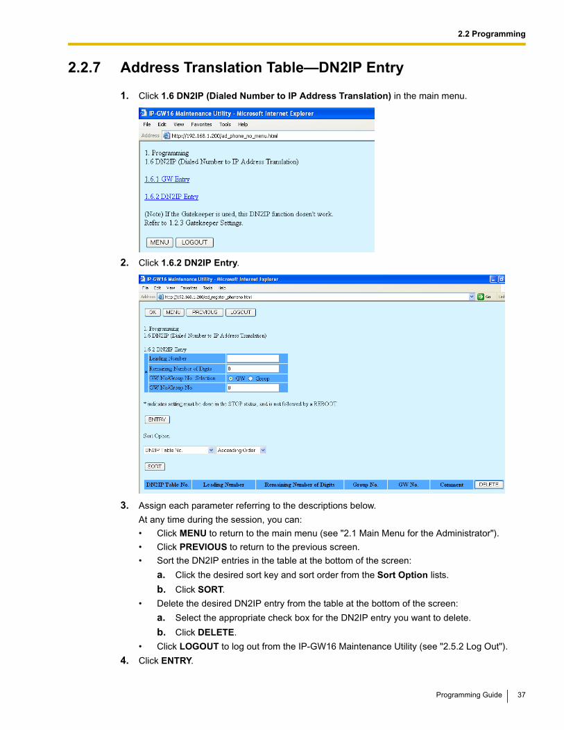
1. Click 1.6 DN2IP (Dialed Number to IP Address Translation) in the main menu.
2. Click 1.6.2 DN2IP Entry.
3. Assign each parameter referring to the descriptions below.
At any time during the session, you can:
• Click MENU to return to the main menu (see "2.1 Main Menu for the Administrator").
• Click PREVIOUS to return to the previous screen.
• Sort the DN2IP entries in the table at the bottom of the screen:
a. Click the desired sort key and sort order from the Sort Option lists.
b. Click SORT.
• Delete the desired DN2IP entry from the table at the bottom of the screen:
a. Select the appropriate check box for the DN2IP entry you want to delete.
b. Click DELETE.
• Click LOGOUT to log out from the IP-GW16 Maintenance Utility (see "2.5.2 Log Out").
4. Click ENTRY.
Programming Guide 37
2.2 Programming
A maximum of 512 DN2IP entries can be created.
5. Click OK.
You will see a confirmation screen.
NoteIf your entry contains an invalid value, you will be prompted to correct your input. Enter correct values for the parameters shown in red and try again.
6. Confirm your entry and click OK.
To return to the previous screen, click CANCEL.
Parameter DescriptionsThe parameters indicated with "*" must be changed while the VoIP Gateway Card is in the "STOP" status (see "2.3.1 Status Control"). The changes do not have to be followed by a reboot to become effective.
DN2IP EntryThe parameters below are used to create DN2IP entries based on the gateway entries created previously (see "2.2.6 Address Translation Table—GW Entry"). The DN2IP entries associate dialed numbers and IP address of the destination; therefore, a caller can reach the destination by dialing the number without knowing the destination IP address.
For a programming example, refer to "3.2.5 Programming the Address Translation Table" of the VoIP Gateway Card Getting Started.
Note
If you are using a gatekeeper, create the DN2IP entries only for the local card. In this case, you can create up to 4 DN2IP entries per card.Note that if you are not using a gatekeeper, there is no maximum number of DN2IP entries.
Parameter & Description Default Value Range
* Leading NumberSpecifies the leading digits in dialed numbers by which to associate calls with the appropriate destination.
For example, to associate calls with dialed numbers "950-xxxx" and "951-xxxx" with separate destinations, it is necessary to make 2 DN2IP entries with respective numbers, "950" and "951".
No default Max. 30 digits
* Remaining Number of DigitsSpecifies the number of digits to be dialed following the leading number to access the destination.
For example, if the dialed numbers are either "950-xxxx" or "951-xxxx" and the numbers "950" and "951" are specified for the parameter Leading Number respectively, specify the number "4" in this parameter.
0 0 to 29
* GW No/Group No. SelectionSpecifies the type of destination when making calls: a gateway or a gateway group.
GW GW,Group
38 Programming Guide
2.2 Programming
Detailed Explanations
Automatic Route RedirectionWhen more than one card is installed in a PBX, you can assign them to a single gateway group. Grouping allows you to logically combine the channels of multiple cards in a PBX (there are 16 channels per card). This aids the effective use of channels in a PBX.
The following diagram and tables provide an example of this configuration.
Example of Configuration
In the diagram below, there are 2 cards (cards B and C) installed in PBX 2.
Example of Gateway Entry Programming
Through gateway entry programming, cards B and C are grouped into a single gateway group.
Example of DN2IP Entry ProgrammingWhen DN2IP entries are programmed as in the table below, calls through card A arrive at gateway group 1, which includes cards B and C.
* GW No/Group No.Specifies the number of the destination gateway or gateway group.
GW No: 0,Group No.: 1
GW No: 0 to 511,Group No.: 1 to 256
Parameter Card A Card B Card C
GW No 0 1 2
Comment IP-GW Card A IP-GW Card B IP-GW Card C
IP Address 192.168.1.1 192.168.1.2 192.168.1.3
Group No. 0 1 1
Parameter To Card A To Gateway Group 1(Cards B and C)
Leading Number 951 952
Parameter & Description Default Value Range
Card AIP Address: 192.168.1.1
PBX 1
• PBX Code: 951• Extension Number: 3 digits
PBX 2
• PBX Code: 952• Extension Number: 4 digits
Card BIP Address: 192.168.1.2
Card CIP Address: 192.168.1.3
Gateway Group 1
IP Network
Programming Guide 39
2.2 Programming
The automatic route redirection feature activates in this configuration. If a call is made through card A to gateway group 1 when all 16 channels of card B are busy, card A automatically redirects the call to card C.
This is possible because by grouping, PBX 1 sees PBX 2 as having a combined set of 32 channels, not 2 separate sets of 16 channels.
NoteThe automatic route redirection feature cannot be used in a network where a gatekeeper is used. For details about gatekeeper settings, refer to "Gatekeeper Settings" in "2.2.2 H.323 Parameters".
Remaining Number of Digits 3 4
GW No/Group No. Selection GW Group
GW No/Group No. 0 1
Parameter To Card A To Gateway Group 1(Cards B and C)
40 Programming Guide
2.2 Programming
2.2.8 Initialization
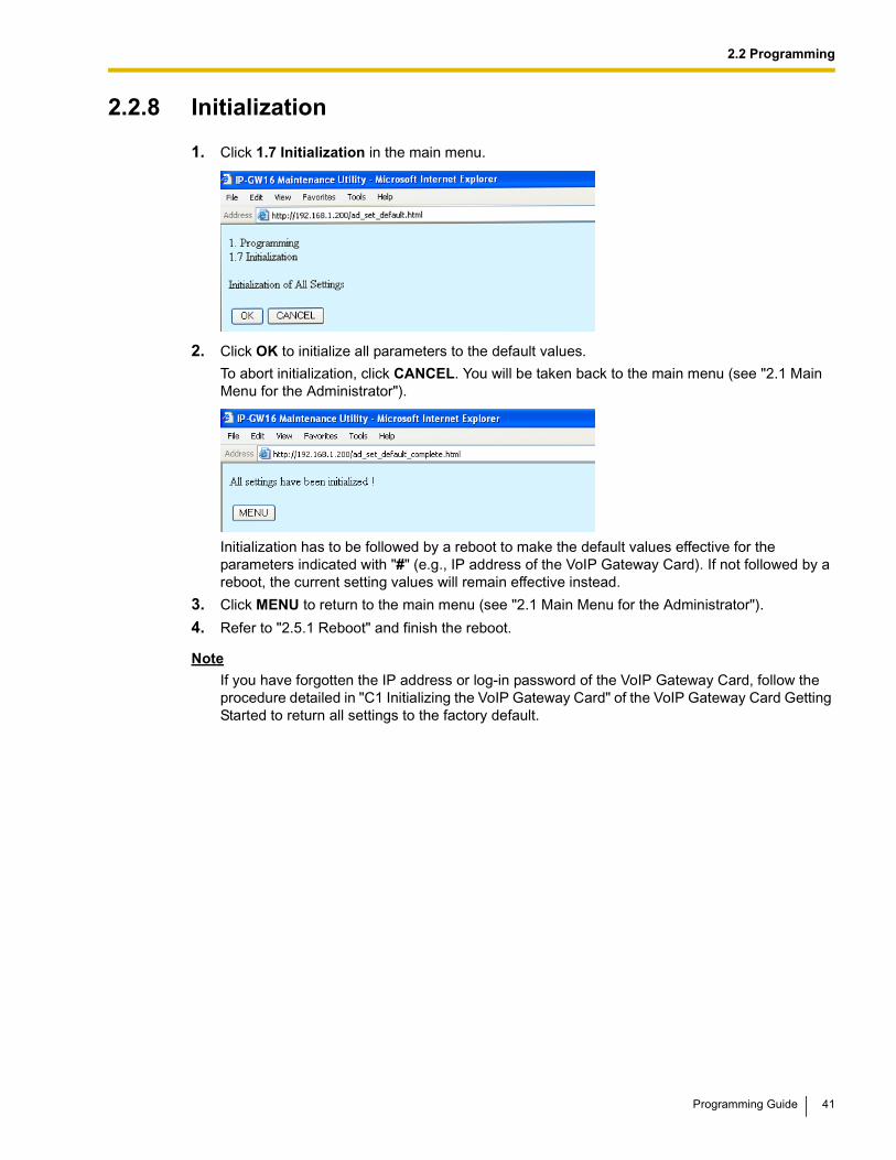
1. Click 1.7 Initialization in the main menu.
2. Click OK to initialize all parameters to the default values.
To abort initialization, click CANCEL. You will be taken back to the main menu (see "2.1 Main Menu for the Administrator").
Initialization has to be followed by a reboot to make the default values effective for the parameters indicated with "#" (e.g., IP address of the VoIP Gateway Card). If not followed by a reboot, the current setting values will remain effective instead.
3. Click MENU to return to the main menu (see "2.1 Main Menu for the Administrator").
4. Refer to "2.5.1 Reboot" and finish the reboot.
NoteIf you have forgotten the IP address or log-in password of the VoIP Gateway Card, follow the procedure detailed in "C1 Initializing the VoIP Gateway Card" of the VoIP Gateway Card Getting Started to return all settings to the factory default.
Programming Guide 41
2.3 Maintenance
2.3 Maintenance
2.3.1 Status Control
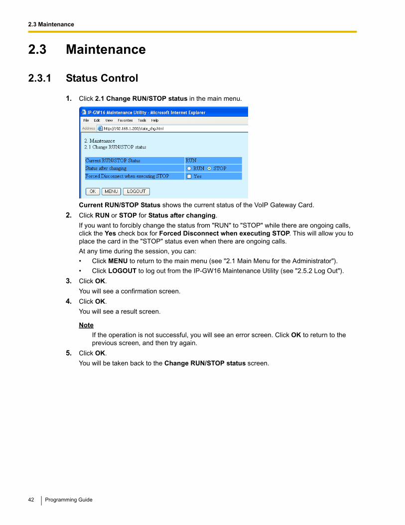
1. Click 2.1 Change RUN/STOP status in the main menu.
Current RUN/STOP Status shows the current status of the VoIP Gateway Card.
2. Click RUN or STOP for Status after changing.
If you want to forcibly change the status from "RUN" to "STOP" while there are ongoing calls, click the Yes check box for Forced Disconnect when executing STOP. This will allow you to place the card in the "STOP" status even when there are ongoing calls.
At any time during the session, you can:
• Click MENU to return to the main menu (see "2.1 Main Menu for the Administrator").
• Click LOGOUT to log out from the IP-GW16 Maintenance Utility (see "2.5.2 Log Out").
3. Click OK.
You will see a confirmation screen.
4. Click OK.
You will see a result screen.
Note
If the operation is not successful, you will see an error screen. Click OK to return to the previous screen, and then try again.
5. Click OK.
You will be taken back to the Change RUN/STOP status screen.
42 Programming Guide
2.3 Maintenance
2.3.2 Maintenance Settings
1. Click 2.2 Maintenance Settings in the main menu.
2. Assign each parameter referring to the descriptions below.
At any time during the session, you can:
• Click ALL CLEAR to return all parameters to their previous values.
• Click MENU to return to the main menu (see "2.1 Main Menu for the Administrator").
• Click LOGOUT to log out from the IP-GW16 Maintenance Utility (see "2.5.2 Log Out").
3. Click OK.
You will see a confirmation screen.
Note
If your entry contains an invalid value, you will be prompted to correct your input. Enter correct values for the parameters shown in red and try again.
4. Confirm your entry and click OK.
To return to the previous screen, click CANCEL.
Parameter DescriptionsThe parameters indicated with "*" must be changed while the VoIP Gateway Card is in the "STOP" status (see "2.3.1 Status Control"). The changes do not have to be followed by a reboot to become effective.
Username/Password Settings
Parameter & Description Default Value Range
Username for AdministratorAdministrator-level log-in user name.
Administrator Max. 16 characters
Programming Guide 43
2.3 Maintenance
Programming Auto Disconnect Time Settings
Periodic Diagnosis Time Interval Settings
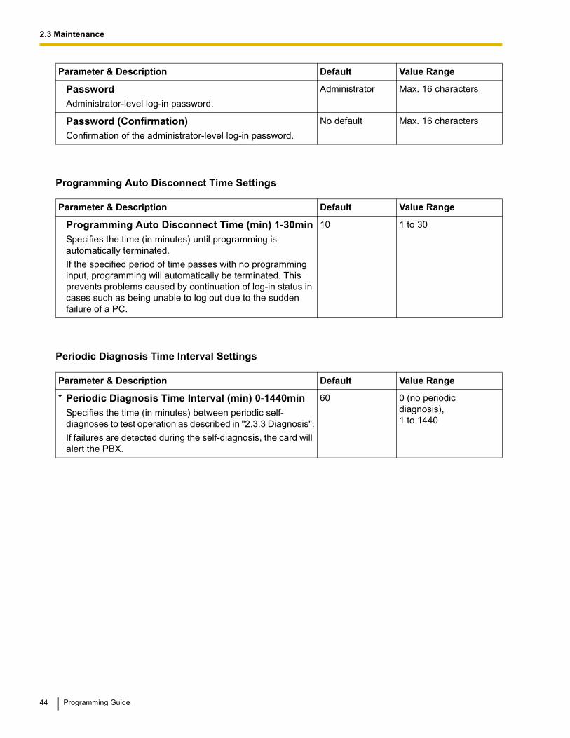
PasswordAdministrator-level log-in password.
Administrator Max. 16 characters
Password (Confirmation)Confirmation of the administrator-level log-in password.
No default Max. 16 characters
Parameter & Description Default Value Range
Programming Auto Disconnect Time (min) 1-30minSpecifies the time (in minutes) until programming is automatically terminated.
If the specified period of time passes with no programming input, programming will automatically be terminated. This prevents problems caused by continuation of log-in status in cases such as being unable to log out due to the sudden failure of a PC.
10 1 to 30
Parameter & Description Default Value Range
* Periodic Diagnosis Time Interval (min) 0-1440minSpecifies the time (in minutes) between periodic self-diagnoses to test operation as described in "2.3.3 Diagnosis".
If failures are detected during the self-diagnosis, the card will alert the PBX.
60 0 (no periodic diagnosis),1 to 1440
Parameter & Description Default Value Range
44 Programming Guide
2.3 Maintenance
Version
Parameter & Description Default Value Range
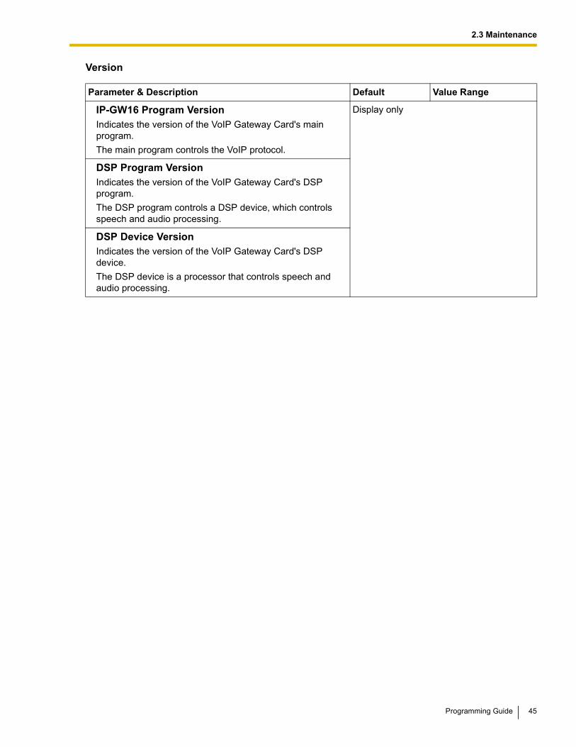
IP-GW16 Program VersionIndicates the version of the VoIP Gateway Card's main program.
The main program controls the VoIP protocol.
Display only
DSP Program VersionIndicates the version of the VoIP Gateway Card's DSP program.
The DSP program controls a DSP device, which controls speech and audio processing.
DSP Device VersionIndicates the version of the VoIP Gateway Card's DSP device.
The DSP device is a processor that controls speech and audio processing.
Programming Guide 45
2.3 Maintenance
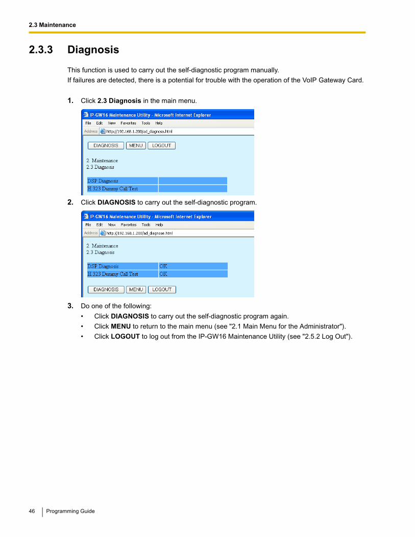
2.3.3 Diagnosis
This function is used to carry out the self-diagnostic program manually.
If failures are detected, there is a potential for trouble with the operation of the VoIP Gateway Card.
1. Click 2.3 Diagnosis in the main menu.
2. Click DIAGNOSIS to carry out the self-diagnostic program.
3. Do one of the following:
• Click DIAGNOSIS to carry out the self-diagnostic program again.
• Click MENU to return to the main menu (see "2.1 Main Menu for the Administrator").
• Click LOGOUT to log out from the IP-GW16 Maintenance Utility (see "2.5.2 Log Out").
46 Programming Guide
2.3 Maintenance
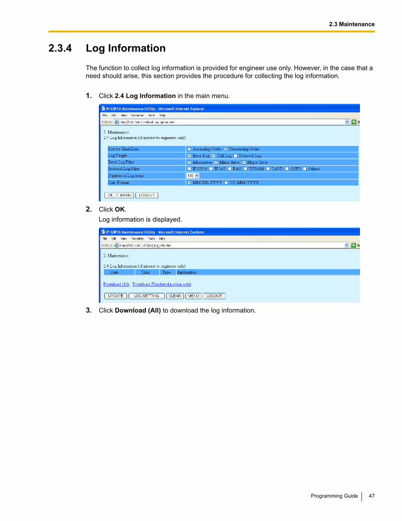
2.3.4 Log Information
The function to collect log information is provided for engineer use only. However, in the case that a need should arise, this section provides the procedure for collecting the log information.
1. Click 2.4 Log Information in the main menu.
2. Click OK.
Log information is displayed.
3. Click Download (All) to download the log information.
Programming Guide 47
2.4 Data Management
2.4 Data ManagementIt is strongly recommended that you download the configuration data and the address translation table (DN2IP) data from the VoIP Gateway Card for backup and archive purposes.
The following sections provide the procedures for downloading and uploading.
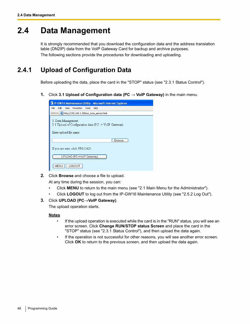
2.4.1 Upload of Configuration Data
Before uploading the data, place the card in the "STOP" status (see "2.3.1 Status Control").
1. Click 3.1 Upload of Configuration data (PC → VoIP Gateway) in the main menu.
2. Click Browse and choose a file to upload.
At any time during the session, you can:
• Click MENU to return to the main menu (see "2.1 Main Menu for the Administrator").
• Click LOGOUT to log out from the IP-GW16 Maintenance Utility (see "2.5.2 Log Out").
3. Click UPLOAD (PC→VoIP Gateway).
The upload operation starts.
Notes
• If the upload operation is executed while the card is in the "RUN" status, you will see an error screen. Click Change RUN/STOP status Screen and place the card in the "STOP" status (see "2.3.1 Status Control"), and then upload the data again.
• If the operation is not successful for other reasons, you will see another error screen. Click OK to return to the previous screen, and then upload the data again.
48 Programming Guide
2.4 Data Management
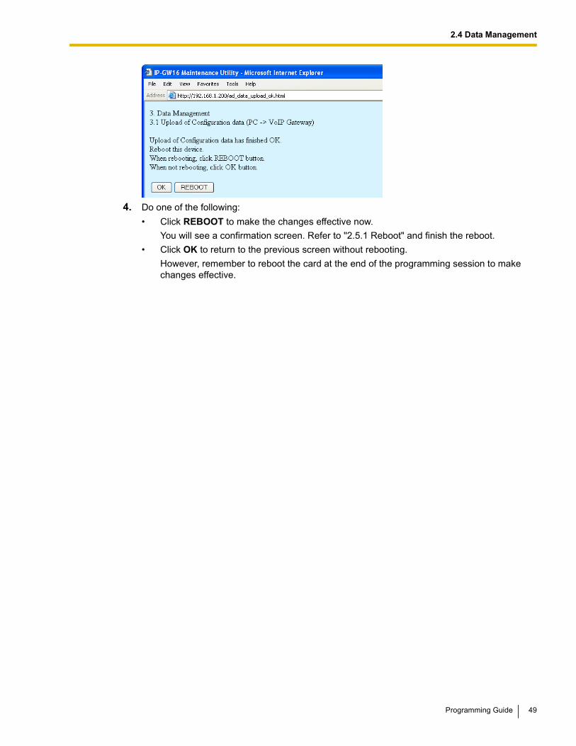
4. Do one of the following:
• Click REBOOT to make the changes effective now.
You will see a confirmation screen. Refer to "2.5.1 Reboot" and finish the reboot.
• Click OK to return to the previous screen without rebooting.
However, remember to reboot the card at the end of the programming session to make changes effective.
Programming Guide 49
2.4 Data Management
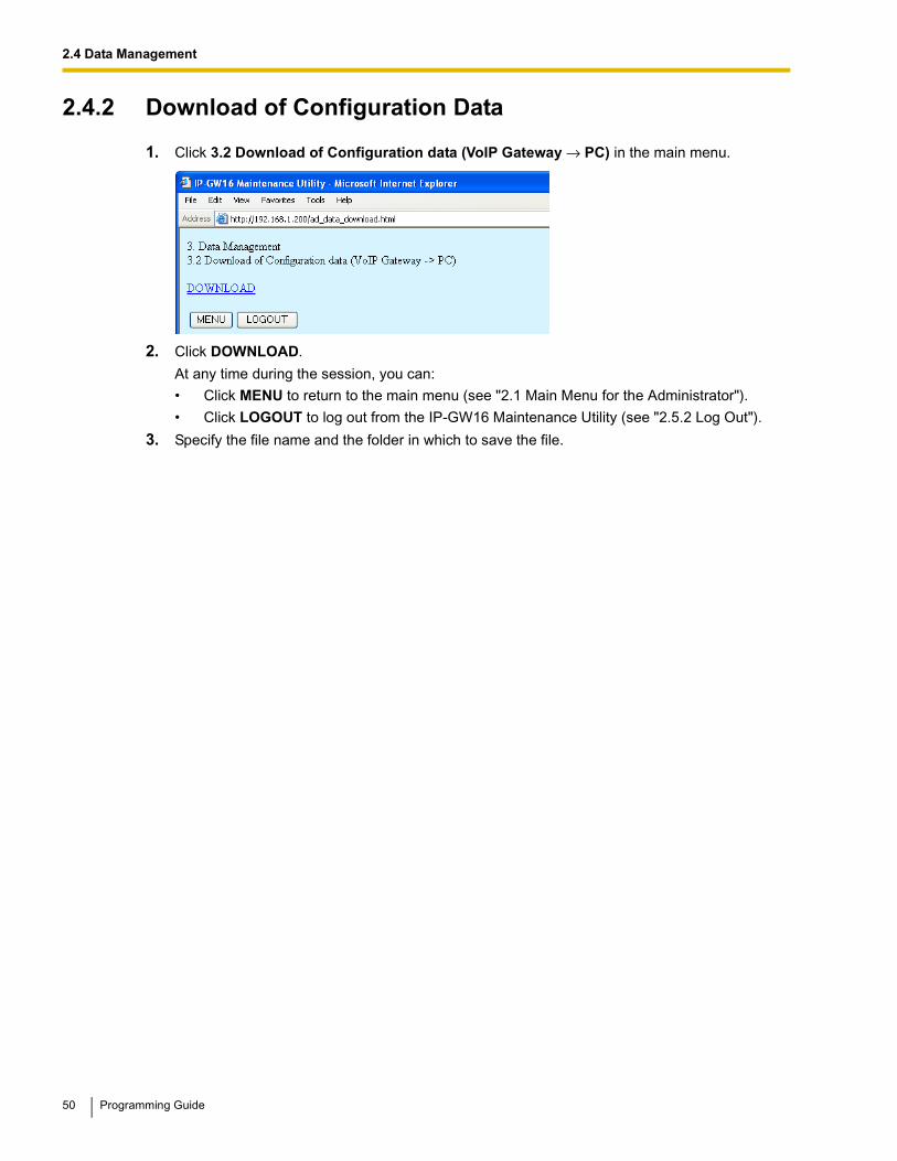
2.4.2 Download of Configuration Data
1. Click 3.2 Download of Configuration data (VoIP Gateway → PC) in the main menu.
2. Click DOWNLOAD.
At any time during the session, you can:
• Click MENU to return to the main menu (see "2.1 Main Menu for the Administrator").
• Click LOGOUT to log out from the IP-GW16 Maintenance Utility (see "2.5.2 Log Out").
3. Specify the file name and the folder in which to save the file.
50 Programming Guide
2.4 Data Management
2.4.3 Upload of Address Translation Table
Before uploading the data, place the card in the "STOP" status (see "2.3.1 Status Control").
1. Click 3.3 Upload of DN2IP data (PC → VoIP Gateway) in the main menu.
2. Click Browse and choose a file to upload.
At any time during the session, you can:
• Click MENU to return to the main menu (see "2.1 Main Menu for the Administrator").
• Click LOGOUT to log out from the IP-GW16 Maintenance Utility (see "2.5.2 Log Out").
3. Click UPLOAD (PC→VoIP Gateway).
The upload operation starts.
Notes
• If the upload operation is executed while the card is in the "RUN" status, you will see an error screen. Click Change RUN/STOP status Screen and place the card in the "STOP" status (see "2.3.1 Status Control"), and then upload the data again.
• If the operation is not successful for other reasons, you will see another error screen. Click OK to return to the previous screen, and then upload the data again.
4. Do one of the following:
• Click REBOOT to make the changes effective now.
You will see a confirmation screen. Refer to "2.5.1 Reboot" and finish the reboot.
• Click OK to return to the previous screen without rebooting.
Programming Guide 51
2.4 Data Management
However, remember to reboot the card at the end of the programming session to make changes effective.
52 Programming Guide
2.4 Data Management
2.4.4 Download of Address Translation Table
1. Click 3.4 Download of DN2IP data (VoIP Gateway → PC) in the main menu.
2. Click DOWNLOAD.
At any time during the session, you can:
• Click MENU to return to the main menu (see "2.1 Main Menu for the Administrator").
• Click LOGOUT to log out from the IP-GW16 Maintenance Utility (see "2.5.2 Log Out").
3. Specify the file name and the folder in which to save the file.
Programming Guide 53
2.5 Others
2.5 Others
2.5.1 Reboot
1. Click REBOOT in the main menu.
2. Click REBOOT.
To return to the main menu, click CANCEL (see "2.1 Main Menu for the Administrator").
Note
If the reboot operation is not successful, you will see an error page.
3. To continue programming, click LOGIN Screen and log in again.
You will see the log-in screen (see "1.1 Starting the IP-GW16 Maintenance Utility").
54 Programming Guide
2.5 Others
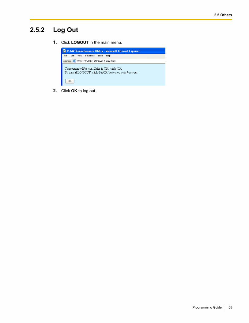
2.5.2 Log Out
1. Click LOGOUT in the main menu.
2. Click OK to log out.
Programming Guide 55
2.5 Others
56 Programming Guide
Section 3
Installer Functions
This section provides operating instructions for the IP-GW16 Maintenance Utility when logged in as the Installer.
Programming Guide 57
3.1 Main Menu for the Installer
3.1 Main Menu for the InstallerThe IP-GW16 Maintenance Utility provides the following menu to a user logged in as the Installer.
2.2 Handling of Firmware Page 3.3.2 Handling of Firmware Page
Menu Section Reference
REBOOT 3.4.1 Reboot
LOGOUT 3.4.2 Log Out
58 Programming Guide
3.2 Maintenance
3.2 Maintenance
3.2.1 Status Control
1. Click 1.1 Change RUN/STOP status in the main menu.
Current RUN/STOP Status shows the current status of the VoIP Gateway Card.
2. Click RUN or STOP for Status after changing.
If you want to forcibly change the status from "RUN" to "STOP" while there are ongoing calls, click the Yes check box for Forced Disconnect when executing STOP. This will allow you to place the card in the "STOP" status even when there are ongoing calls.
At any time during the session, you can:
• Click MENU to return to the main menu (see "3.1 Main Menu for the Installer").
• Click LOGOUT to log out from the IP-GW16 Maintenance Utility (see "3.4.2 Log Out").
3. Click OK.
You will see a confirmation screen.
4. Click OK.
You will see a result screen.
NoteIf the operation is not successful, you will see an error screen. Click OK to return to the previous screen, and then try again.
5. Click OK.
You will be taken back to the Change RUN/STOP status screen.
Programming Guide 59
3.2 Maintenance
3.2.2 Maintenance Settings
1. Click 1.2 Maintenance Settings in the main menu.
2. Assign each parameter referring to the descriptions below.
At any time during the session, you can:
• Click ALL CLEAR to return all parameters to their previous values.
• Click MENU to return to the main menu (see "3.1 Main Menu for the Installer").
• Click LOGOUT to log out from the IP-GW16 Maintenance Utility (see "3.4.2 Log Out").
3. Click OK.
You will see a confirmation screen.
Note
If your entry contains an invalid value, you will be prompted to correct your input. Enter correct values for the parameters shown in red and try again.
4. Confirm your entry and click OK.
To return to the previous screen, click CANCEL.
Parameter Descriptions
Username/Password Settings
Parameter & Description Default Value Range
Username for InstallerInstaller-level log-in user name.
Installer Max. 16 characters
PasswordInstaller-level log-in password.
Installer Max. 16 characters
Password (Confirmation)Confirmation of the installer-level log-in password.
No default Max. 16 characters
60 Programming Guide
3.2 Maintenance
Version
Parameter & Description Default Value Range
IP-GW16 Program VersionIndicates the version of the VoIP Gateway Card's main program.
The main program controls the VoIP protocol.
Display only
DSP Program VersionIndicates the version of the VoIP Gateway Card's DSP program.
The DSP program controls a DSP device, which controls speech and audio processing.
DSP Device VersionIndicates the version of the VoIP Gateway Card's DSP device.
The DSP device is a processor that controls speech and audio processing.
Programming Guide 61
3.3 Data Management
3.3 Data ManagementThe upload and update operations of the firmware data are closely related. First follow the procedure as described in "3.3.1 Upload of Firmware Data" to upload new firmware data to the VoIP Gateway Card, and then go on to "3.3.2 Handling of Firmware Page" to update the card with the newly uploaded firmware data.
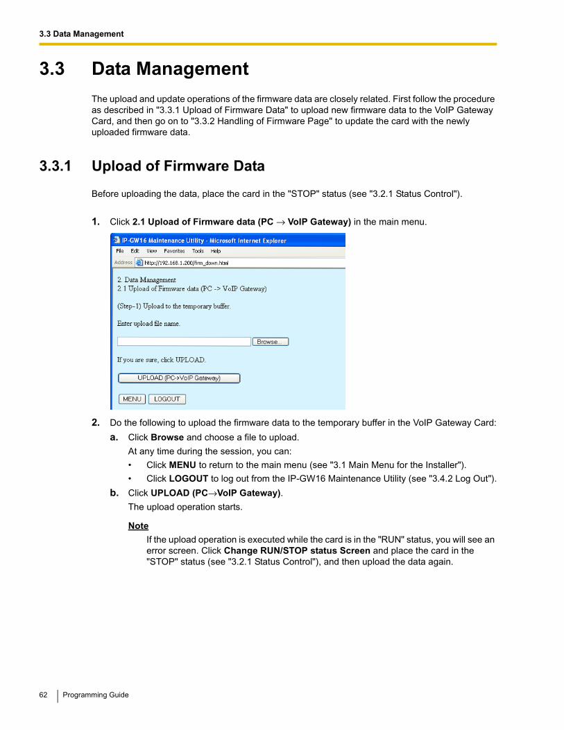
3.3.1 Upload of Firmware Data
Before uploading the data, place the card in the "STOP" status (see "3.2.1 Status Control").
1. Click 2.1 Upload of Firmware data (PC → VoIP Gateway) in the main menu.
2. Do the following to upload the firmware data to the temporary buffer in the VoIP Gateway Card:
a. Click Browse and choose a file to upload.
At any time during the session, you can:
• Click MENU to return to the main menu (see "3.1 Main Menu for the Installer").
• Click LOGOUT to log out from the IP-GW16 Maintenance Utility (see "3.4.2 Log Out").
b. Click UPLOAD (PC→VoIP Gateway).
The upload operation starts.
Note
If the upload operation is executed while the card is in the "RUN" status, you will see an error screen. Click Change RUN/STOP status Screen and place the card in the "STOP" status (see "3.2.1 Status Control"), and then upload the data again.
62 Programming Guide
3.3 Data Management
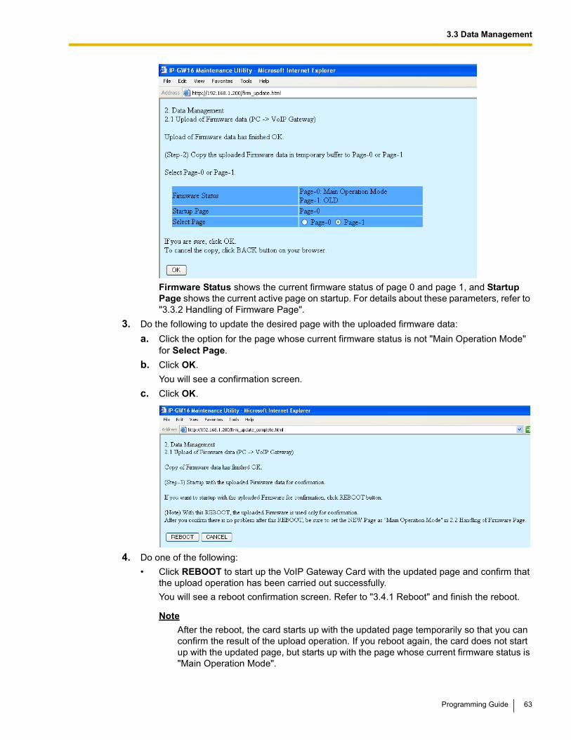
Firmware Status shows the current firmware status of page 0 and page 1, and Startup Page shows the current active page on startup. For details about these parameters, refer to "3.3.2 Handling of Firmware Page".
3. Do the following to update the desired page with the uploaded firmware data:
a. Click the option for the page whose current firmware status is not "Main Operation Mode" for Select Page.
b. Click OK.
You will see a confirmation screen.
c. Click OK.
4. Do one of the following:
• Click REBOOT to start up the VoIP Gateway Card with the updated page and confirm that the upload operation has been carried out successfully.
You will see a reboot confirmation screen. Refer to "3.4.1 Reboot" and finish the reboot.
Note
After the reboot, the card starts up with the updated page temporarily so that you can confirm the result of the upload operation. If you reboot again, the card does not start up with the updated page, but starts up with the page whose current firmware status is "Main Operation Mode".
Programming Guide 63
3.3 Data Management
• Click CANCEL to return to the main menu without starting up the card with the updated page.
5. Switch the firmware status of the updated page from "NEW" to "Main Operation Mode".
After the previous step (with or without a reboot), the firmware status of the updated page is still "NEW". To set the updated page as the active page on startup, you must change its firmware status to "Main Operation Mode". For instructions, refer to "3.3.2 Handling of Firmware Page".
The following is a sample image of the screen in which you can set the active page on startup:
64 Programming Guide
3.3 Data Management
3.3.2 Handling of Firmware Page
1. Click 2.2 Handling of Firmware Page in the main menu.
For details about the parameters on this screen, refer to the descriptions below.
2. Click Main Operation Mode for Operation to set the desired page as the active page on startup.
Note
Do not click Empty, as it is an option provided for engineer use only.
At any time during the session, you can:
• Click MENU to return to the main menu (see "3.1 Main Menu for the Installer").
• Click LOGOUT to log out from the IP-GW16 Maintenance Utility (see "3.4.2 Log Out").
3. Click the option for the page in the "NEW" status for Select Page to specify it as the target page of the operation.
4. Click OK.
You will see a confirmation screen.
5. Click OK.
You will see a result screen.
6. Click OK.
You will be taken back to the Handling of Firmware Page screen.
Parameter Descriptions
Parameter & Description Default Value Range
IP-GW16 Program VersionIndicates the version of the VoIP Gateway Card's main program in the firmware data of the corresponding page.
Display only
DSP Program VersionIndicates the version of the VoIP Gateway Card's DSP program in the firmware data of the corresponding page.
Display only
Programming Guide 65
3.3 Data Management
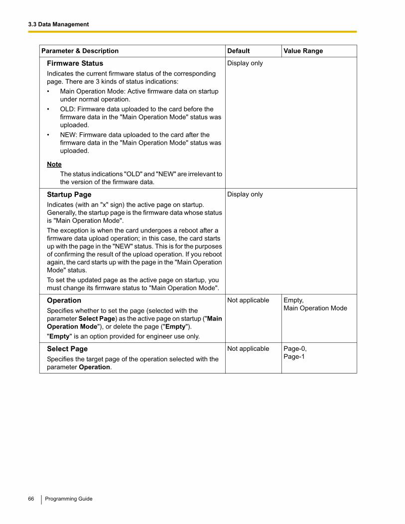
Firmware StatusIndicates the current firmware status of the corresponding page. There are 3 kinds of status indications:
• Main Operation Mode: Active firmware data on startup under normal operation.
• OLD: Firmware data uploaded to the card before the firmware data in the "Main Operation Mode" status was uploaded.
• NEW: Firmware data uploaded to the card after the firmware data in the "Main Operation Mode" status was uploaded.
NoteThe status indications "OLD" and "NEW" are irrelevant to the version of the firmware data.
Display only
Startup PageIndicates (with an "x" sign) the active page on startup. Generally, the startup page is the firmware data whose status is "Main Operation Mode".
The exception is when the card undergoes a reboot after a firmware data upload operation; in this case, the card starts up with the page in the "NEW" status. This is for the purposes of confirming the result of the upload operation. If you reboot again, the card starts up with the page in the "Main Operation Mode" status.
To set the updated page as the active page on startup, you must change its firmware status to "Main Operation Mode".
Display only
OperationSpecifies whether to set the page (selected with the parameter Select Page) as the active page on startup ("Main Operation Mode"), or delete the page ("Empty").
"Empty" is an option provided for engineer use only.
Not applicable Empty,Main Operation Mode
Select PageSpecifies the target page of the operation selected with the parameter Operation.
Not applicable Page-0,Page-1
Parameter & Description Default Value Range
66 Programming Guide
3.4 Others
3.4 Others
3.4.1 Reboot
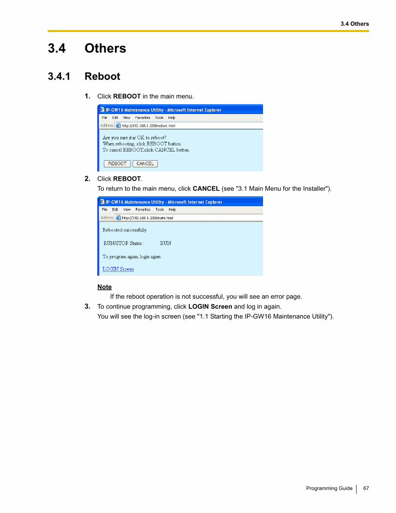
1. Click REBOOT in the main menu.
2. Click REBOOT.
To return to the main menu, click CANCEL (see "3.1 Main Menu for the Installer").
Note
If the reboot operation is not successful, you will see an error page.
3. To continue programming, click LOGIN Screen and log in again.
You will see the log-in screen (see "1.1 Starting the IP-GW16 Maintenance Utility").
Programming Guide 67
3.4 Others
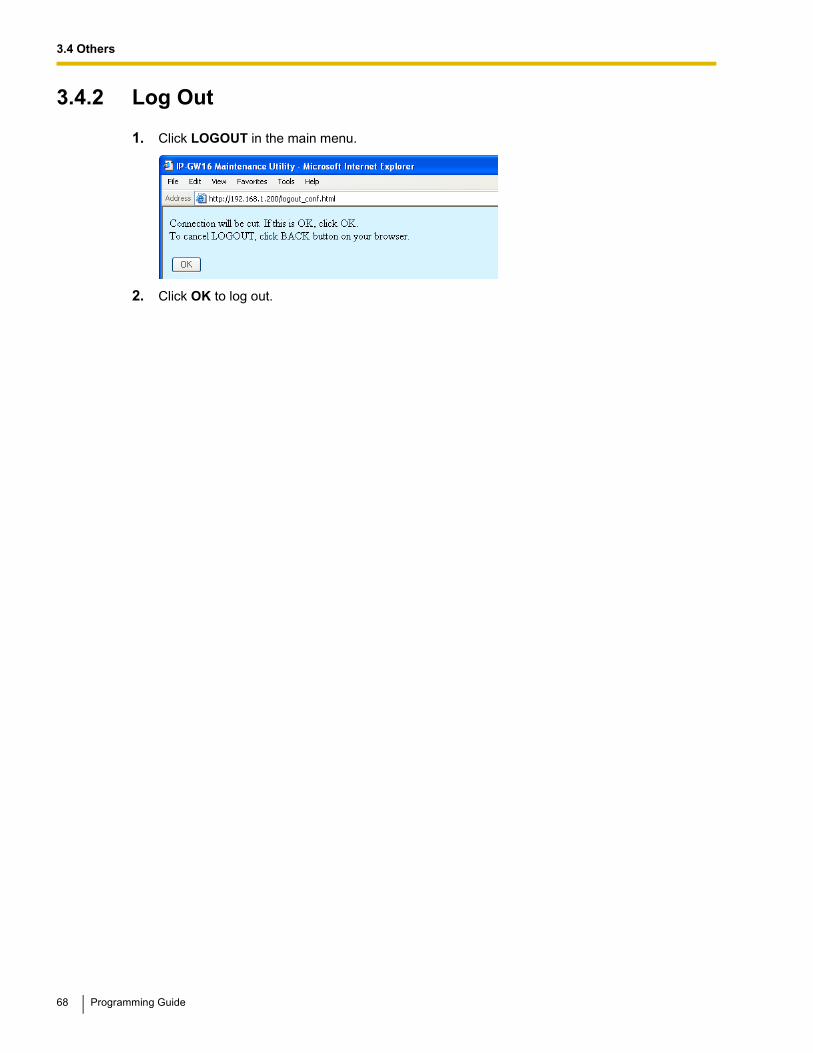
3.4.2 Log Out
1. Click LOGOUT in the main menu.
2. Click OK to log out.
68 Programming Guide
Programming Guide 69
Index
Index
AAutomatic Route Redirection 39
BBandwidth 23
CCall Signaling Model 17Change RUN/STOP status 42, 59CODEC Frame Settings 20, 23
DDefault Gateway 11DHCP Settings 11Diagnosis 46Dialing Settings 26DiffServ 19Digit End Code 27DN2IP (Dialed Number to IP Address Translation) 34, 37DN2IP Entry 37, 38Download of Address Translation Table 53Download of Configuration Data 50DSCP 19, 23DSP Program Version 65DTMF Detection 21, 24DTMF Detection Level 22DTMF Relay 21, 24
Copyright:This material is copyrighted by Panasonic Communications Co., Ltd., and may be reproduced for internal use only. All other reproduction, in whole or in part, is prohibited without the written consent of Panasonic Communications Co., Ltd.