106
Panda_4000i_PMS_Book_eng.R04 7.4.09 Panda 4000i PMS Super silent technology 230V 50Hz 4kW Fischer Panda GmbH
Pan
da_4
000i
_PM
S_B
ook_
eng.
R04
7.4.
09
Panda 4000i PMS
Super silent technology230V 50Hz 4kW
Fischer Panda GmbH
2
Revision
Document
Akcuell: Panda_4000i_PMS_Book_eng.R04_7.4.09
Replace Panda_4000i_PMS_Book_eng.R03
Revision Page
Position Wassersammler korrigiert - Sonderaustattung Stellmotor eingefügt

7.4.09 Panda_4000i_PMS_Book_eng.R04 - Table of contents Page 1
Table of contentsPanda 4000i PMS.................................... ................................................................................ 1
Revision........................................... ........................................................................................ 2
A Panda 4000i ...................................... ............................................................................. 3
A.1 Components ..................................... ................................................................................ 3
A.2 Range of operation ............................. .............................................................................. 4
A.2.1 Main features of the Panda 4000i ....................................................................................... 4
Panda 4000i
Part 1: Generator Manual........................... ............................................................................ 5
......................................................................................................................................... 5
Current revision status ............................ .............................................................................. 6
Safety first ....................................... ........................................................................................ 8
Tools .............................................. .......................................................................................... 9
Safety Precautions ................................. .............................................................................. 12
B 7 Panda 4000i PMS generator....................... .............................................................. 15
B.1 Type plate at the generator .................... ....................................................................... 15
B.2 Description of the Generator.................... ...................................................................... 16
B.2.1 Right Side View ................................................................................................................. 16B.2.2 Left Side View ................................................................................................................... 17B.2.3 Front View ......................................................................................................................... 18B.2.4 Back View .......................................................................................................................... 19B.2.5 View from Above ............................................................................................................... 20
B.3 Details of function units ...................... .......................................................................... 21
B.3.1 Remote control panel - see iControl manual ..................................................................... 21B.3.2 Components of the Cooling System (Raw Water) ............................................................. 21B.3.3 Components of the Cooling System (Fresh Water) ........................................................... 24B.3.4 Components of the Fuel System ....................................................................................... 28B.3.5 Components of Combustion Air ........................................................................................ 31B.3.6 Components of the Electrical System ............................................................................... 34B.3.7 Components of the Oil Circuit ........................................................................................... 37B.3.8 Sensors and switches for operating surveillance .............................................................. 39B.3.9 External Components ........................................................................................................ 41
B.4 Operation Instructions - see separate control pa nel manual ..................................... 42
B.4.1 Daily routine checks before starting - See iControl manual. ............................................. 42B.4.2 Starting Generator - See iControl manual. ........................................................................ 42B.4.3 Stopping the Generator - See iControl manual. ................................................................ 42
C Generator Installation Instructions ............... ............................................................. 43
C.1 Placement ...................................... ................................................................................. 43
C.1.1 Placement and Basemount ............................................................................................... 43C.1.2 Notice for optimal sound insulation ................................................................................... 43

Page 2 Panda_4000i_PMS_Book_eng.R04 - Table of contents 7.4.09
Table of contentsC.2 Generator Connections - Scheme ................. ................................................................ 44
C.2.1 Connections Panda 4000i .................................................................................................. 44
C.3 Cooling System Installation - Raw water ........ .............................................................. 45
C.3.1 General References ........................................................................................................... 45C.3.2 Installation of the thru-vessel fitting in Yachts .................................................................... 45C.3.3 Quality of the raw water sucking in line ............................................................................. 45C.3.4 Installation above waterline ............................................................................................... 46C.3.5 Installation below waterline ................................................................................................ 47
C.4 The Freshwater - Coolant Circuit ............... ................................................................... 48
C.4.1 De-aerating at the first filling of the internal cooling water circuit ....................................... 48
C.5 Watercooled Exhaust System ..................... .................................................................. 49
C.5.1 Installation of the standard exhaust system ....................................................................... 49C.5.2 Exhaust / water separator .................................................................................................. 50C.5.3 Installation exhaust/water separator .................................................................................. 51
C.6 Fuel System Installation ....................... .......................................................................... 52
C.6.1 General References ........................................................................................................... 52C.6.2 The electrical fuel pump ..................................................................................................... 53C.6.3 Connection of the fuel lines at the tank .............................................................................. 54C.6.4 Position of the pre-filter with water separator .................................................................... 54
C.7 Generator DC System-Installation ............... ................................................................. 55
C.7.1 Connection of the 12 V starter battery ............................................................................... 55C.7.2 Fuse ................................................................................................................................... 56C.7.3 Installation of the iControl panel - See iControl Manual ..................................................... 56
C.8 Generator Electric-System-Installation ......... ............................................................... 56
D Generator Failure................................. .........................................................................57
D.1 Tools and measuring instruments ................ ................................................................ 57
D.2 Overloading the Generator ...................... ...................................................................... 57
D.2.1 Low Generator-Output Voltage .......................................................................................... 58
D.3 Starting Problems .............................. ............................................................................. 58
D.3.1 De-aerating the fuel system ............................................................................................... 58D.3.2 Fuel Solenoid Valve ........................................................................................................... 58
D.4 Troubleshooting Table .......................... ......................................................................... 59
E Generator Maintenance Instructions ................ ..........................................................61
E.1 General maintenance instructions ............... ................................................................. 61
E.1.1 Checks before starting ....................................................................................................... 61E.1.2 Hose elements and rubber formed component in the sound cover ................................... 61
E.2 Oil circuit maintenance ........................ .......................................................................... 61
E.3 Execution of an oil change ..................... ....................................................................... 62
E.4 Checking the water separator in the fuel supply ......................................................... 64
E.4.1 De-aerating the fuel system ............................................................................................... 64E.4.2 Replacement of the air filter ............................................................................................... 66
E.5 De-aerating of the coolant circuit / freshwater ............................................................ 67
E.6 The raw water circuit .......................... ............................................................................ 67
E.6.1 Clean raw water filter ......................................................................................................... 67E.6.2 Causes with frequent impeller waste ................................................................................. 68E.6.3 Replacement of the impeller .............................................................................................. 68
E.7 Conservation at longer operation interruption .. .......................................................... 71

7.4.09 Panda_4000i_PMS_Book_eng.R04 - Table of contents Page 3
Table of contentsE.7.1 Measures on preparation of the winter storage ................................................................. 71E.7.2 Initiation at spring .............................................................................................................. 72
F Generator Tables .................................. ....................................................................... 73
F.1 Trouble shooting ............................... ............................................................................. 74
F.2 Technical Data Engine .......................... ......................................................................... 77
F.3 Types of coil .................................. ................................................................................. 78
F.4 Inspection checklist for services .............. .................................................................... 78
F.5 Engine oil ..................................... ................................................................................... 79
F.6 Coolant specifications ......................... .......................................................................... 80
F.7 Measurements ................................... ............................................................................. 81
Panda 4000i - Part 2 Panel Panda iControl Manual ... ........................................................ 83
Current revision status ............................ ............................................................................ 84
A , Panda iControl .................................. ......................................................................... 85
A.1 Safety instructions ............................ ............................................................................. 86
A.2 Connection of the iControl ...................... ....................................................................... 86
A.3 Buttons and display of the iControl ............. ................................................................. 87
A.4 Engine control .................................. ............................................................................... 88
A.5 Operation manual ............................... ............................................................................ 88
A.5.1 Daily routine checks before starting ................................................................................... 88A.5.2 General .............................................................................................................................. 89A.5.3 Long time run of the generator .......................................................................................... 90A.5.4 Start of the generator ........................................................................................................ 90A.5.5 Stop of the generator ......................................................................................................... 90A.5.6 Automatic start .................................................................................................................. 91A.5.7 Additional information ........................................................................................................ 91
A.6 Error warnings ................................. ............................................................................... 91
A.7 Errors ......................................... ...................................................................................... 92
A.8 Electronic board ............................... .............................................................................. 93
A.8.1 Location at the Panda 4000i PMS ..................................................................................... 93
A.9 Technical data ................................. ............................................................................... 93
A.9.1 Intended use ...................................................................................................................... 93A.9.2 Dimensions ........................................................................................................................ 94
Panda 4000i - Part 3 PMGi 4000 Manual .............. ............................................................... 95
Current revision status ............................ ............................................................................ 96
A Panda PMGi 4000 .................................. ...................................................................... 97
A.1 Safety instruction ............................. .............................................................................. 98
A.2 Type plate ..................................... ................................................................................... 98
A.3 Front side/connection side ..................... ....................................................................... 99
A.3.1 Socket pins of the PMGi 4000 ........................................................................................... 99
Page 4 Panda_4000i_PMS_Book_eng.R04 - Table of contents 7.4.09
Table of contentsA.4 Back side - Top side ........................... .......................................................................... 100
A.5 Operation manual ............................... .......................................................................... 101
A.5.1 Primary remarks / Winter operation ................................................................................. 101A.5.2 Load at the PMGi ............................................................................................................. 101A.5.3 Automatic start ................................................................................................................. 101
A.6 Status LED´s ................................... .............................................................................. 101
A.7 Cooling of the PMGi ............................ ......................................................................... 102
A.8 Installation of the PMGi ....................... ......................................................................... 102
A.8.1 Electrical connection. ....................................................................................................... 102A.8.2 Installation of the ferrites .................................................................................................. 103
A.9 Technical Data ................................. ............................................................................. 104
A.9.1 General Data ................................................................................................................... 104A.9.2 Generator Spezifikation ................................................................................................... 104A.9.3 PMGi out .......................................................................................................................... 105
A.10 PMGi protections .............................. ............................................................................ 105
A.10.1 Overload - switch point ................................................................................................... 105A.10.2 Short circiut ...................................................................................................................... 106A.10.3 Under voltage and signal ................................................................................................. 106A.10.4 Overheat ......................................................................................................................... 106
A.11 Dimensions ................................... ............................................................................... 107
A.12 Wiring diagram PGMi with 4000i generator ...... .......................................................... 108
A.13 Wiring diagram PGMi - RCD ..................... ................................................................... 109
A.14 Wiring diagram PGMi - isolation control ....... ............................................................. 110

Panda 4000i
7.4.09 Panda_4000i_PMS_Book_eng.R04 - Chapter A: Panda 4000i - Page 3
A. Panda 4000i
A.1 Components
1. Panda 4000i Generator
Permanent-Magnet-Generator
Art Nr. C10040BX1SV01
Manual see Page 5
Fig. A.1-1: Panda 4000i generator
2. Panel Panda iControl with electronic board at the generator
Art Nr. 21.02.02.011H (Panel)
Art Nr. 21.02.01.005H (electronic board)
Manual see Page 77
Fig. A.1-2: iControl
3. Panda PMGi 4000 Inverter AC/AC 3,5 kW 230 V / 50 Hz
Art Nr. 21.07.03.003H
Manual see Page 91
Fig. A.1-3: PMGi 4000
Panda 4000i
Page 4 Panda_4000i_PMS_Book_eng.R04 - Chapter A: Panda 4000i 7.4.09
A.2 Range of operation
Reliable power supply on sailing boats
A.2.1 Main features of the Panda 4000i
• Extremely high starting capacity, perfect for a Bauer junior 2.2kW compressor!
• 230 V / 50 Hz system for all your domestic appliances!
• Compact and light, takes up less space!
• Super silent sound insulation capsule!
• Graphical Display, easy to operate!
• Option for reduce speed at lower loads, saves fuel!
• Pure sinus wave, higher frequency and voltage stability!
• Optimized engine rpm (2800 rpm) for a long generator life!

Panda 4000i PMS
230V/50Hz 4kW
Fischer Panda GmbH
Panda 4000i
Part 1: Generator Manual

6
Current revision status
Document
Actual: Panda 4000i PMS_generator_eng.R04_7.4.09
Replace: Panda 4000i PMS_generator_eng.R03
Revision Page
Position Wassersammler korrigiert --

7
Fischer Panda
FISCHER GENERATORS have been manufactured since 1978 and are a well-known brand for first class dieselgenerators with especially effective sound-insulation. Fischer has been one of the leading manufacturers in respect ofquality and know-how during this period.
FISCHER, as the worldwide manufacturer of modern marine diesel generators, developed the Sailor-Silent series forexample and produced a GPR sound-insulated capsule as early as 1979 and the basis for new generator technology.
The companies Fischer and Icemaster amalgamated under the direction of Icemaster in 1988, in order to concentrateon the development of new products. Production was moved to Paderborn.
The amalgamation of the two qualified companies led to the development of a complete new programme within a shortspace of time. The generator sets developed at that time set new technological standards worldwide.
The generators became more efficient and powerful than other generators in the same nominal performance range,because of the improved cooling. Panda generator demonstrated its superiority in several tests by renowned institutesand magazines during the past years. The patented VCS (voltage Control System) means it can meet all demandsincluding motor speed. The start-booster (ASB) means Panda generators meet the highest demands in respect ofvoltage stability and starting values A Panda generator, with the same drive motor, produces 15 % more effective outputthan the majority of conventional generators. This superiority in efficiency also ensures a fuel saving to the same extent.
The 100 % water-cooled Panda generators are currently manufactured in the performance range from 2 to 100 kW invarious versions. Fast running motors are preferred for performances up to approx. 30 kW (nominal speed 3.000 rpm).The heavier slow runners are preferred for the higher range. The fast running generators have proved themselvesmany times for many uses, that they meet the demands in quality of yachts and vehicles, and offer space and weightsaving of 50 % compared to slow running generators.
In addition to the Panda series, Fischer Panda also supply the super compact high-tech sound-insulated batterycharging generators from the DC/AC Panda AGT series, which is a very interesting solution for the production of mobilepower.
The new HTG-alternators ensure that a charging rate of 285 amps is achieved that was scarcely thought possible forthis compact construction. This alternator replaces a separate shipboard generators (constant 230 volts AC with up to3500 kW from the main machine)
Fischer Panda GmbH, 33104 Paderborn, reserves all rights regarding text and graphics. Details are given to the best of our knowledge. No liability is accepted forcorrectness. Technical modifications for improving the product without previous notice may be undertaken without notice. Before installation, it must be ensured that thepictures, diagrams and related material are applicable to the aggregate supplied. Enquiries must be made in case of doubt.
Icemaster GmbH Fischer MarineGenerators
Conclusion Fischer - Icemaster GmbH
100 % water cooled Pan-da generators
Panda Vehicle Genera-tors
since 1977
since 1978
since 1988
since 1988
since 1988

8
Safety first
These symbols are used throughout this manual and on labels on the maschine itself to warn of the possibility ofpersonal injutry. Read these instructions carefully. It is essential that you read the instructions and safety regulationsbefore you attempt to assemble or use unit.
This danger symbol refers to toxic danger and draws attention to special warnings,instructions or procedures which, if not strictly observed, may result in severepersonal injury or loss of life.
This danger symbol refers to electric danger and draws attention to specialwarnings, instructions or procedures which, if not strictly observed, may result inelectrical shock which will result in severe personal injury or loss of life.
This danger symbol refers to electric danger and draws attention to specialwarnings, instructions or procedures which, if not strictly observed, may result inelectrical shock which will result in severe personal injury or loss of life.
This warning symbol draws attention to special warnings, instructions or procedureswhich, if not strictly observed, may result in damage or destruction of equipment,severe personal injury or loss of life.
This warning symbol draws attention to special warnings, instructions or procedureswhich, if not strictly observed, may result in damage or destruction of equipment

9
Tools
This symbols are used throughout this manual to show which tool must be used at maintenance or installation.
Spanners
X = number of spanner
Hook wrench for oil filter
Screw driver, for slotted head screws and for recessed head screws
Multimeter, multimeter with capacitor measuring
Infrared temperature mesuring pistol
Current clamp (DC for synchron generators; AC for asynchron generators)
X

10
Socket wrench set
Hexagon wrench keys

11
CALIFORNIA
Proposition 65 Warning
Diesel engine exhaust and some of its constituents are known to the State of California to cause cance r,
birth defects, and other reproductive harm.
Attention, Important Directions regarding Operation !
1. The installation certificate must be completed when taken into use, and certified by a signature.
2. The installation certificate must be despatched within two weeks of use to Fischer Panda.
3. The official guaranty confirmation will be completed by Fischer Panda after receipt and sent to the customer.
4. A guaranty must be shown to make any claims.
Claims against the guaranty will not be accepted of the above said instructions are not, or only partially, carried out.
Manufacturer declaration in terms of the machine gu ideline 98/37/EG .
The generator is in such a way developed that all assembly groups correspond to the CE guidelines. If machine gui-deline 98/37/EG is applicable, then it is forbidden to bring the generator into operation until it has been determinedthat the system into which the generator is to be installed in also corresponds to the regulations of the machine gui-deline 98/37/EG. This concerns among other things the exhaust system, cooling system and the electrical installa-tion.
The evaluation of the "protection against contact" can only be accomplished in connection with the respectivesystem. Likewise among other things responsibility for correct electrical connections, a safe ground wire connection,foreign body and humidity protection, protection against humidity due to excessive condensation as well as the over-heating through appropriate and inappropriate use in its installed state on the respective machine lies within theresponsibility of those who undertake installation of the generator in the system.
Use the advantages of the customer registration:
• Thus you receive extended product information, which are sometimes safety-relevant
• You receive free upgrades, if necessary
Further advantages:
With your full information, the Fischer Panda technicians can give you fast assistance, since 90 % of the distur-bances result from errors in the periphery.
Problems according to errors in the installation can be recognized in advance.
Technical Support by Internet: [email protected]

12
Safety Precautions
The electrical Installations may only be carried ou t by trained and
examined personnel!
The generator may not be taken into use with the co ver removed.
The rotating parts (belt-pulley, belts, etc) must be covered and protected so that there is no danger to life and body!If a sound insulation cover must be produced at the place of installation, then well-placed signs must show that thegenerator can only be switched on with a closed capsule.All servicing-, maintenance or repair work may only be carried out, when the motor is not running.
Electrical power: DANGER TO LIFE!
Electrical voltages above 48 volts (battery chargers greater than 36 volts) are always dangerous tolife). The rules of the respective regional authority must be adhered to. Only an electrician maycarry out installation of the electrical connections for safety reasons.
ATTENTION!
Do not connect the minus pole of the starter batter y to the ground of the boat because of galvanic rea son.
CAUTION!
Contact of the electrical contacts may be DANGER TO LIFE!
The PMGi cable must be secured at the generator and at the PMGi with appropriate safety devices.
The generator is also included into the CO 2 - fire-extinguishing system.
Fire protection measures
All construction units in the environment of energized parts, which carry more than 50 Amp., must be fire protection-moderately secured.
All junction points at the energized parts must be examined on heating up regularly (infrared thermometers).

13
Safety Instrictions for handling batteries
These instructions must be noticed additionally to the instructions of the battery manufacturer:
• If the batteries are working, someone should be in your near area to help you in a case of emergency.
• Water and soap must be hold ready if battery acid corrode your skin.
• Wear eye protection and protective clothing. During working with the batteries don´t touch the eyes.
• If you got an acid splash on your skin or clothing, wash it out with much water and soap.
• If you got acid in your eyes, rinse them immediately with clear water until no cauterization is noticeable. Visit a doc-tor immediately.
• Don´t smoke in the area of the batteries. Avoid open fires. In the area of batteries there is a danger of explosions.
• Pay attention that no tools will fall on the battery poles, if necessary cover them up.
• During the installation, don´t wear a wrist watch or arm jewels, under these circumstances you can create a battery short-circuit. Skin burnings could be the result.
• Protect every battery contact against unintentional touch.
• Use only cyclical profoundly dischargeable batteries. Starter batteries are not appropriate. Lead-gel batteries are commended. They are maintenance-free, profoundly dischargeable and produce no gas.
• Do not charge a frozen battery.
• Avoid a battery short-curcuit.
• Take care that the battery is good ventilated in order to drain off developing gas.
• The battery connection terminals must be checked for tightness before operating.
• The battery connection cable must be mounted carefully. Check for incorrect heating at operation with load. The vibrating devices must be checked regulary for scour points and flaw in the isolation.

14
Blank

5
5 Safety steps to follow if someone is the victim of electrical shock
Do not try to pull or grab the individual.
Send for help as soon as possible.
If possible, turn off the electrical power.
If you cannot turn off the electrical power, pull, push, or lift the person to safety using awooden pole, rope, or some nonconductive material.
After the injured person is free of contact with the source of electrical shock, move them ashort distance away and immediately start necessary first aid procedures.
1
1
1
2
1
3
1
4
1
5

6
WHEN AN ADULT STOPS BREATHING
WARNING
DO NOT attempt to perform the rescue breathing tech niques provided on this page, unlesscertified. Performance of these techniques by uncer tified personnel could result in furtherinjury or death to the victim.
1 Does the Person Respond? 2 Shout, "Help!"
Tap or gently shake victim.
Shout, "Are you OK?"
Call people who can phone for help.
3 Roll Person onto Back.
Roll victim toward you by pulling slowly.
4 Open Airway. 5 Check for Breathing.
Tilt head back, and lift chin.
Shout, "Are you OK?"
Look, listen, and feel for breathingfor 3 to 5 seconds.
6 Give 2 Full Breaths.
Keep head tilted back.
Pinch nose shut.
Seal your lips tight around victim'smouth.
Give 2 full breaths for 1 to 1½ secondseach.
7 Check for Pulse at side of Neck. 8 Phone EMS for Help.
Feel for pulse for 5 to 10 seconds. Send someone to call an ambu-lance.
9 Begin Rescue Breathing. 10 Recheck Pulse Every Minute.
Keep head tilted back.
Lift chin.
Pinch nose shut.
Give 1 full breath every 5 seconds.
Look, listen, and feel for breathing bet-ween breaths.
Keep head tilted back.
Feel for pulse for 5 to 10 seconds.
If victim has pulse, not breathing,continue rescue breathing. If nopulse, begin CPR.

7 Panda 4000i PMS generator
7.4.09 Panda 4000i PMS_generator_eng.R04 - Chapter: B: 7 Panda 4000i PMS generator Page 15
B. 7 Panda 4000i PMS generator
B.1 Type plate at the generator
Fig. B.1-1: Type plate
Fig. B.1-2: Discription type plate

7 Panda 4000i PMS generator
Page 16 Panda 4000i PMS_generator_eng.R04 - Chapter: B: 7 Panda 4000i PMS generator 7.4.09
B.2 Description of the Generator
B.2.1 Right Side View
Fig. B.2.1-1: Right side view
01
03
04
06
10
05 09
11
0807
02
01) Housing with iControl electronic board (DO NOT OPEN)02) Coolant pipe, raw water pump - heat exchanger03) Toothed belt04) Raw water pump05) Oil drain hose06) Sound cover base part
07) Passage for battery cable (+)08) Passage for batterie cable (-)09) Raw water inlet10) Engine Kubota EA30011) Generator housing with coil

7 Panda 4000i PMS generator
7.4.09 Panda 4000i PMS_generator_eng.R04 - Chapter: B: 7 Panda 4000i PMS generator Page 17
B.2.2 Left Side View
Fig. B.2.2-1: Left side view
01
12
06
05
11
13
02
04
03
07 08 1009
01) Generator housing with coil02) Water-cooled exhaust elbow03) Raw water injection pipe04) Coolant pipe, water tank - heat exchanger05) Connection external ventilation valve06) Sound cover base part07) Engine Kubota EA300
08) Injection nozzle09) Coolant pipe, water pump - engine10) Coolant water pump11) Suction port at air suction housing12) Cooling water tank13) Cooling water filler neck

7 Panda 4000i PMS generator
Page 18 Panda 4000i PMS_generator_eng.R04 - Chapter: B: 7 Panda 4000i PMS generator 7.4.09
B.2.3 Front View
Fig. B.2.3-1: Front side view
1314
01
09 08 07 06 0511 10
02 03 04
12
01) Solenoid switch for starter motor02) Starter motor03) Oil pressure switch04) Housing with iControl electronic board „DO NOT OPEN“05) Raw water pump06) Pulley07) Ground connection terminal
08) Oil dipstick09) Engine oil filler neck10) Oil drain hose11) Fuel solenoid valve12) Fuse 30A 13) Air suction housing with air filter inlet14) Suction port
7 Panda 4000i PMS generator
7.4.09 Panda 4000i PMS_generator_eng.R04 - Chapter: B: 7 Panda 4000i PMS generator Page 19
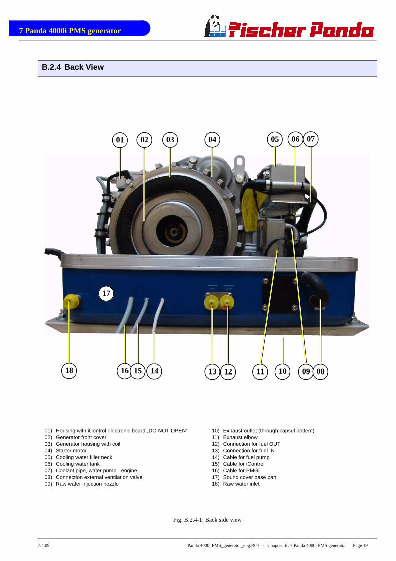
B.2.4 Back View
Fig. B.2.4-1: Back side view
18 16 15 14 1013 12
07060504030201
11 09
17
08
01) Housing with iControl electronic board „DO NOT OPEN“02) Generator front cover03) Generator housing with coil04) Starter motor05) Cooling water filler neck06) Cooling water tank07) Coolant pipe, water pump - engine08) Connection external ventilation valve09) Raw water injection nozzle
10) Exhaust outlet (through capsul bottem)11) Exhaust elbow12) Connection for fuel OUT13) Connection for fuel IN14) Cable for fuel pump15) Cable for iControl16) Cable for PMGi17) Sound cover base part18) Raw water inlet

7 Panda 4000i PMS generator
Page 20 Panda 4000i PMS_generator_eng.R04 - Chapter: B: 7 Panda 4000i PMS generator - Description of the Generator 7.4.09
B.2.5 View from Above
Fig. B.2.5-1: Top side view
01
13 07 06
04 0502
11 09 0810
03
12
01) Cooling water filler neck02) Connection external ventilation valve03) Cooling water tank04) Exhaust out (through capsul bottem)05) Generator housing with coil06) iControl electronic board under cover „DO NOT OPEN“07) Pulley
08) Starter motor09) Fuel solenoid valve10) Solenoid switch for starter motor11) Air suction housing with air filter inlet12) Coolant overflow hose13) Suction port

7 Panda 4000i PMS generator
7.4.09 Panda 4000i PMS_generator_eng.R04 - Chapter: B: 7 Panda 4000i PMS generator - Description of the Generator Page 21
B.3 Details of function units
B.3.1 Remote control panel - see iControl manual
B.3.2 Components of the Cooling System (Raw Water)
Expansionstank withfillercap
HeatexchangerFreshwater side
elect. Waterpump
Engine Kubota EA 300
Watercooled exhaustelbow
Overflow hose
Overpressure valvein fillercap
Thermosensorat Engine
Thermosensorat exhaustelbow
iControl elektronic board
cooledside
hotside
coolant
HeatexchangerSeewater side
SeewaterImpellerpump
Seewater
externalventilation valve
Exhaust/Waterout
Water injec.in exhaust hose

7 Panda 4000i PMS generator
Page 22 Panda 4000i PMS_generator_eng.R04 - Chapter: B: 7 Panda 4000i PMS generator - Description of the Generator 7.4.09
Raw water inlet
The diagram shows the supply pipes forthe generator. The connection neck forthe raw water connection is shown on theleft hand side. The cross-section of theintake pipe should be nominally largerthan the generator connection.
Fig. B.3.2-1: Raw water inlet
Raw water impeller pump
The raw water pump is fitted with a rubberimpeller. This pump is self-inductive. If,for example, you forget to open the seavalve, then you must expect the impellerto be destroyed after a short period oftime. It is recommended to store severalimpellers on board as spare parts.
Fig. B.3.2-2: Raw water pump
Heat exchanger
Separates the raw water system fromthe fresh water system, so that the gene-rator components do not have contactwith the seawater circulation system. Theseawater is fed direct to the exhaust con-nection piece at the heat exchanger out-let.
Fig. B.3.2-3: Heat exchanger
7 Panda 4000i PMS generator
7.4.09 Panda 4000i PMS_generator_eng.R04 - Chapter: B: 7 Panda 4000i PMS generator - Description of the Generator Page 23
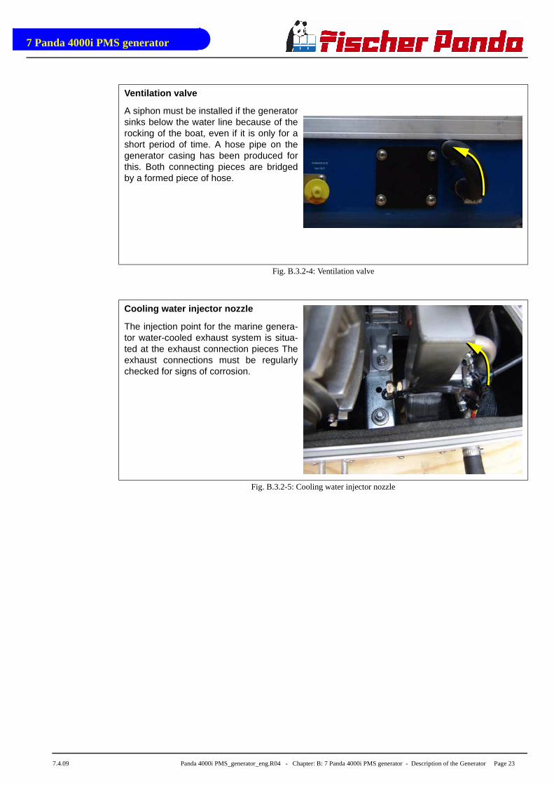
Ventilation valve
A siphon must be installed if the generatorsinks below the water line because of therocking of the boat, even if it is only for ashort period of time. A hose pipe on thegenerator casing has been produced forthis. Both connecting pieces are bridgedby a formed piece of hose.
Fig. B.3.2-4: Ventilation valve
Cooling water injector nozzle
The injection point for the marine genera-tor water-cooled exhaust system is situa-ted at the exhaust connection pieces Theexhaust connections must be regularlychecked for signs of corrosion.
Fig. B.3.2-5: Cooling water injector nozzle

7 Panda 4000i PMS generator
Page 24 Panda 4000i PMS_generator_eng.R04 - Chapter: B: 7 Panda 4000i PMS generator - Description of the Generator 7.4.09
B.3.3 Components of the Cooling System (Fresh Water)
Expansionstank withfillercap
HeatexchangerFreshwater side
elect. Waterpump
Engine Kubota EA 300
Watercooled exhaustelbow
Overflow hose
Overpressure valvein fillercap
Thermosensorat Engine
Thermosensorat exhaustelbow
iControl elektronic board
cooledside
hotside
coolant
HeatexchangerSeewater side
SeewaterImpellerpump
Seewater
externalventilation valve
Exhaust/Waterout
Water injec.in exhaust hose

7 Panda 4000i PMS generator
7.4.09 Panda 4000i PMS_generator_eng.R04 - Chapter: B: 7 Panda 4000i PMS generator - Description of the Generator Page 25
Cooling water filler neck
The cooling water filler neck is situated atthe cooling water tank and only used,when the generator is initially started.Since the generator is normally already fil-led with cooling water, these componentsare only by the user, if repairs are to becarried out.
Fig. B.3.3-1: Cooling water filler neck
Freshwater backflow
The cooling water is fed to the heatexchanger from the cooling water tank bymeans of the pipe shown in the figure.
Fig. B.3.3-2: Freshwater backflow
Heat exchanger
Separates the raw water system from thefresh water system.
Fig. B.3.3-3: Heat exchanger

7 Panda 4000i PMS generator
Page 26 Panda 4000i PMS_generator_eng.R04 - Chapter: B: 7 Panda 4000i PMS generator - Description of the Generator 7.4.09
Internal cooling water pump
The electric cooling water pump (seearrow) aids the circulation of the internalfreshwater system.
Fig. B.3.3-4: Internal cooling water pump
Coolant pipe, cooling water pump - engine
Fig. B.3.3-5: Coolant pipe
Coolant connection at the engine (in)
Water intake to the engine
Fig. B.3.3-6: Cooant connection block at the engine

7 Panda 4000i PMS generator
7.4.09 Panda 4000i PMS_generator_eng.R04 - Chapter: B: 7 Panda 4000i PMS generator - Description of the Generator Page 27
Coolant connection at the engine (out)
Water outtake of the engine to the heatexchanger
Fig. B.3.3-7: Cooantn connection block engine
Ventilation pipe
The ventilation pipe to the water tank.
Fig. B.3.3-8: Ventilation pipe
Overflow hose
The overflow hose goes out through thesound cover base
Fig. B.3.3-9: Ventilation pipe

7 Panda 4000i PMS generator
Page 28 Panda 4000i PMS_generator_eng.R04 - Chapter: B: 7 Panda 4000i PMS generator - Description of the Generator 7.4.09
B.3.4 Components of the Fuel System
external Tank external elec. fuelpump
fuel stop solonoid
fuel injection nozzle
fuel in
fuel out
air filter housing
engineKubota EA300
exhaust elbow
glow plug
automatic venting filler cap with strainer
injection pump
Fuel filter +water seperator
fuel in
exhaust out
combustionair in
7 Panda 4000i PMS generator
7.4.09 Panda 4000i PMS_generator_eng.R04 - Chapter: B: 7 Panda 4000i PMS generator - Description of the Generator Page 29
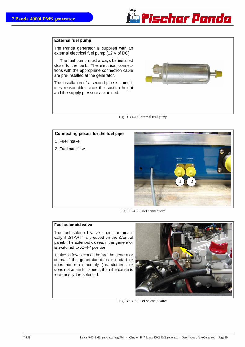
External fuel pump
The Panda generator is supplied with anexternal electrical fuel pump (12 V of DC).
The fuel pump must always be installedclose to the tank. The electrical connec-tions with the appropriate connection cableare pre-installed at the generator.
The installation of a second pipe is someti-mes reasonable, since the suction heightand the supply pressure are limited.
Fig. B.3.4-1: External fuel pump
Connecting pieces for the fuel pipe
1. Fuel intake
2. Fuel backflow
Fig. B.3.4-2: Fuel connections
Fuel solenoid valve
The fuel solenoid valve opens automati-cally if „START“ is pressed on the iControlpanel. The solenoid closes, if the generatoris switched to „OFF“ position.
It takes a few seconds before the generatorstops. If the generator does not start ordoes not run smoothly (i.e. stutters), ordoes not attain full speed, then the cause isfore-mostly the solenoid.
Fig. B.3.4-3: Fuel solenoid valve
1 2

7 Panda 4000i PMS generator
Page 30 Panda 4000i PMS_generator_eng.R04 - Chapter: B: 7 Panda 4000i PMS generator - Description of the Generator 7.4.09
Injection nozzle
If the engine does not start after the venti-lation, the fuel injection line must be deae-rated.
Fig. B.3.4-4: Injection nozzle
Glow plug
The glow plugs serve the pre-chamber forthe heating with cold start. The glowdevice must be operated, if the tempera-ture of the generator is below 16 ° C. Thisis practically the case with each start. Theglow device and starter button are set sothat neither may be used at the sametime.
Fig. B.3.4-5: Glow plug
7 Panda 4000i PMS generator
7.4.09 Panda 4000i PMS_generator_eng.R04 - Chapter: B: 7 Panda 4000i PMS generator - Description of the Generator Page 31
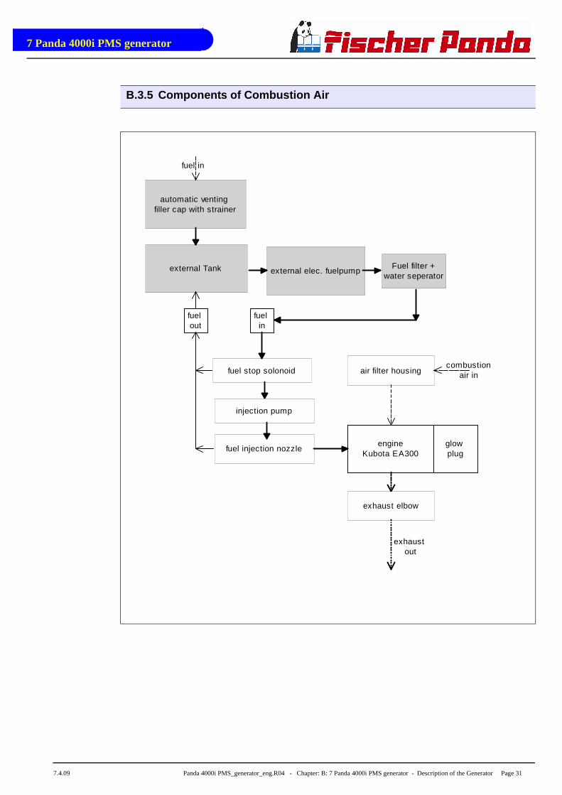
B.3.5 Components of Combustion Air
external Tank external elec. fuelpump
fuel stop solonoid
fuel injection nozzle
fuel in
fuel out
air filter housing
engineKubota EA300
exhaust elbow
glow plug
automatic venting filler cap with strainer
injection pump
Fuel filter +water seperator
fuel in
exhaust out
combustionair in
7 Panda 4000i PMS generator
Page 32 Panda 4000i PMS_generator_eng.R04 - Chapter: B: 7 Panda 4000i PMS generator - Description of the Generator 7.4.09
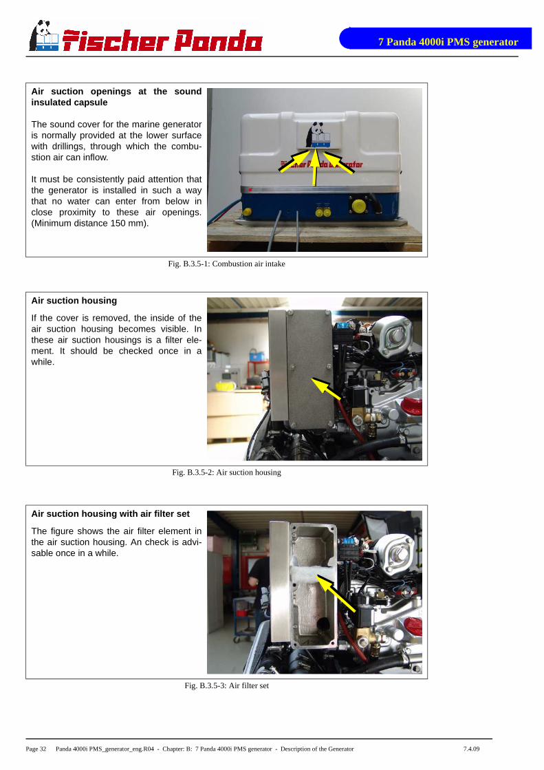
Air suction openings at the soundinsulated capsule
The sound cover for the marine generatoris normally provided at the lower surfacewith drillings, through which the combu-stion air can inflow.
It must be consistently paid attention thatthe generator is installed in such a waythat no water can enter from below inclose proximity to these air openings.(Minimum distance 150 mm).
Fig. B.3.5-1: Combustion air intake
Air suction housing
If the cover is removed, the inside of theair suction housing becomes visible. Inthese air suction housings is a filter ele-ment. It should be checked once in awhile.
Fig. B.3.5-2: Air suction housing
Air suction housing with air filter set
The figure shows the air filter element inthe air suction housing. An check is advi-sable once in a while.
Fig. B.3.5-3: Air filter set
7 Panda 4000i PMS generator
7.4.09 Panda 4000i PMS_generator_eng.R04 - Chapter: B: 7 Panda 4000i PMS generator - Description of the Generator Page 33
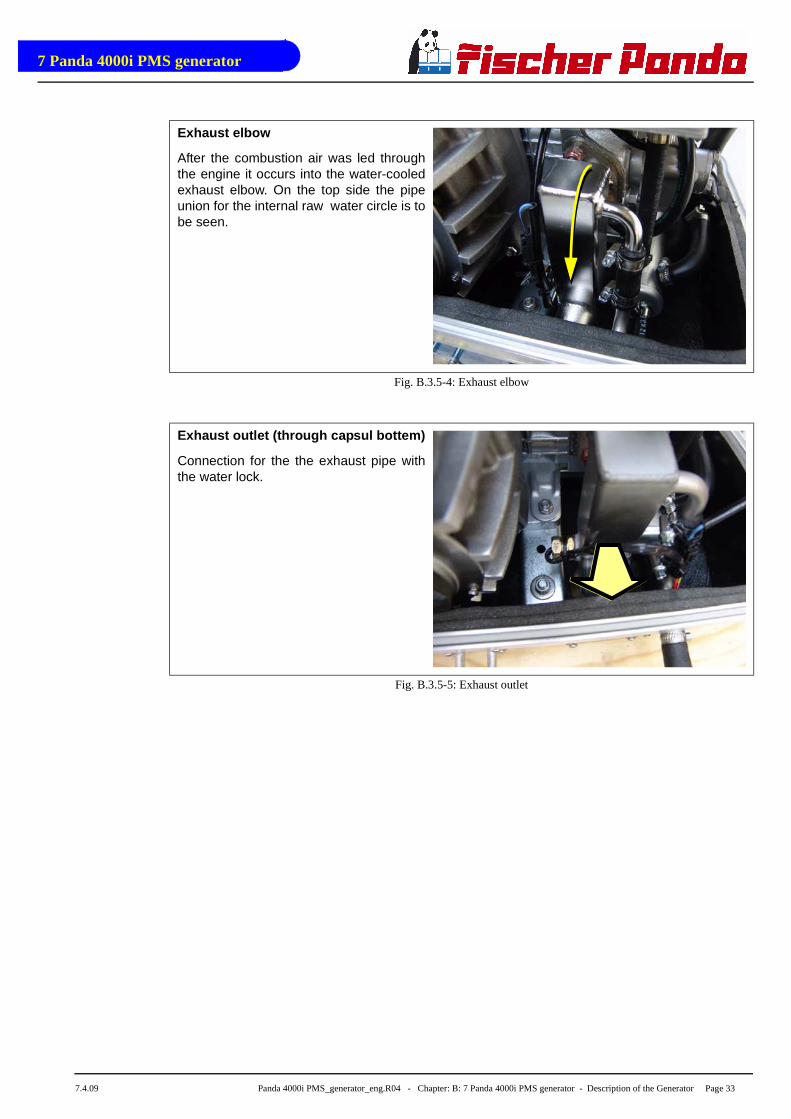
Exhaust elbow
After the combustion air was led throughthe engine it occurs into the water-cooledexhaust elbow. On the top side the pipeunion for the internal raw water circle is tobe seen.
Fig. B.3.5-4: Exhaust elbow
Exhaust outlet (through capsul bottem)
Connection for the the exhaust pipe withthe water lock.
Fig. B.3.5-5: Exhaust outlet

7 Panda 4000i PMS generator
Page 34 Panda 4000i PMS_generator_eng.R04 - Chapter: B: 7 Panda 4000i PMS generator - Description of the Generator 7.4.09
B.3.6 Components of the Electrical System

7 Panda 4000i PMS generator
7.4.09 Panda 4000i PMS_generator_eng.R04 - Chapter: B: 7 Panda 4000i PMS generator - Description of the Generator Page 35
Passage for battery cable
The battery cables of the starter batterymust be laid through this passage to theclamps
Fig. B.3.6-1: Passage
Clamps for battery cable
1. Clamp (-) for battery cable (-)
Fig. B.3.6-2: Connections battery cable
Clamps for battery cable
1. Clamp (+) for battery cable (+).
Fig. B.3.6-3: Connections battery cable
1 2
1
1
7 Panda 4000i PMS generator
Page 36 Panda 4000i PMS_generator_eng.R04 - Chapter: B: 7 Panda 4000i PMS generator - Description of the Generator 7.4.09
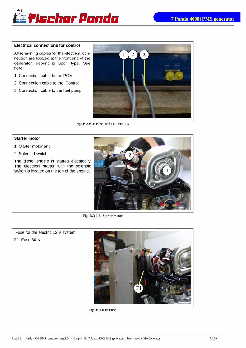
Electrical connections for control
All remaining cables for the electrical con-nection are located at the front end of thegenerator, depending upon type. Seehere:
1. Connection cable to the PGMi
2. Connecttion cable to the iControl
3. Connection cable to the fuel pump
Fig. B.3.6-4: Electrical connections
Starter motor
1. Starter motor and
2. Solenoid switch
The diesel engine is started electrically.The electrical starter with the solenoidswitch is located on the top of the engine.
Fig. B.3.6-5: Starter motor
Fuse for the electric 12 V system
F1. Fuse 30 A
Fig. B.3.6-6: Fuse
31 2
1
2
F1
7 Panda 4000i PMS generator
7.4.09 Panda 4000i PMS_generator_eng.R04 - Chapter: B: 7 Panda 4000i PMS generator - Description of the Generator Page 37
B.3.7 Components of the Oil Circuit
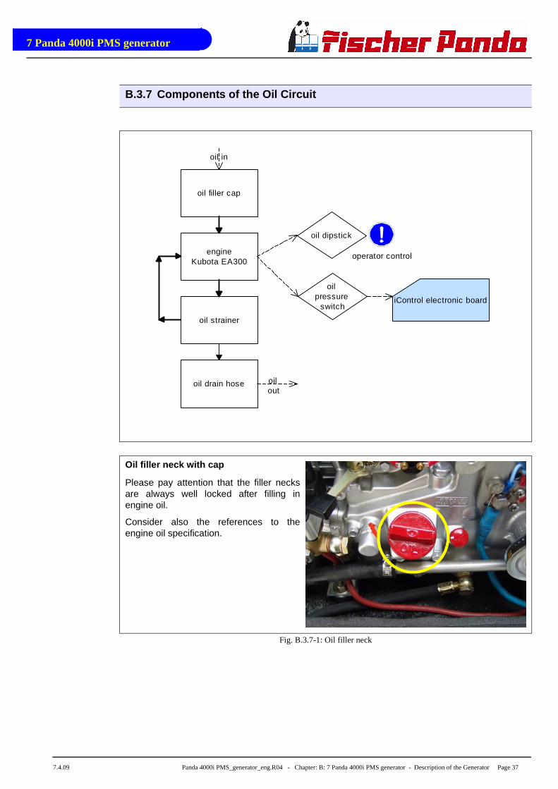
Oil filler neck with cap
Please pay attention that the filler necksare always well locked after filling inengine oil.
Consider also the references to theengine oil specification.
Fig. B.3.7-1: Oil filler neck
oil filler cap
engineKubota EA300
oil strainer
oil dipstick
oil pressure
switch
oil drain hose
iControl electronic board
operator control
oil in
oil out

7 Panda 4000i PMS generator
Page 38 Panda 4000i PMS_generator_eng.R04 - Chapter: B: 7 Panda 4000i PMS generator - Description of the Generator 7.4.09
Oil dipstick
At the dipstick the permissible level is indi-cated by the markings "maximum" and"minimum". The engine oil should benever filled up beyond the maximum con-ditions.
Fig. B.3.7-2: Oil dipstick
Oil strainer
The oil strainer should be cleaned every500 operating hours.
Fig. B.3.7-3: Oil srtainer
Oil drain hose
The Panda generator is equipped so thatthe engine oil can be drained by means ofa hose. The generator should be installedin such a way, that a collecting basin canbe placed deeply enough. If this is notpossible, an electrical oil drain pump mustbe installed.
Note: Lubricating oil should be drainedin warm condition!
Fig. B.3.7-4: Oil drain hose
7 Panda 4000i PMS generator
7.4.09 Panda 4000i PMS_generator_eng.R04 - Chapter: B: 7 Panda 4000i PMS generator - Description of the Generator Page 39
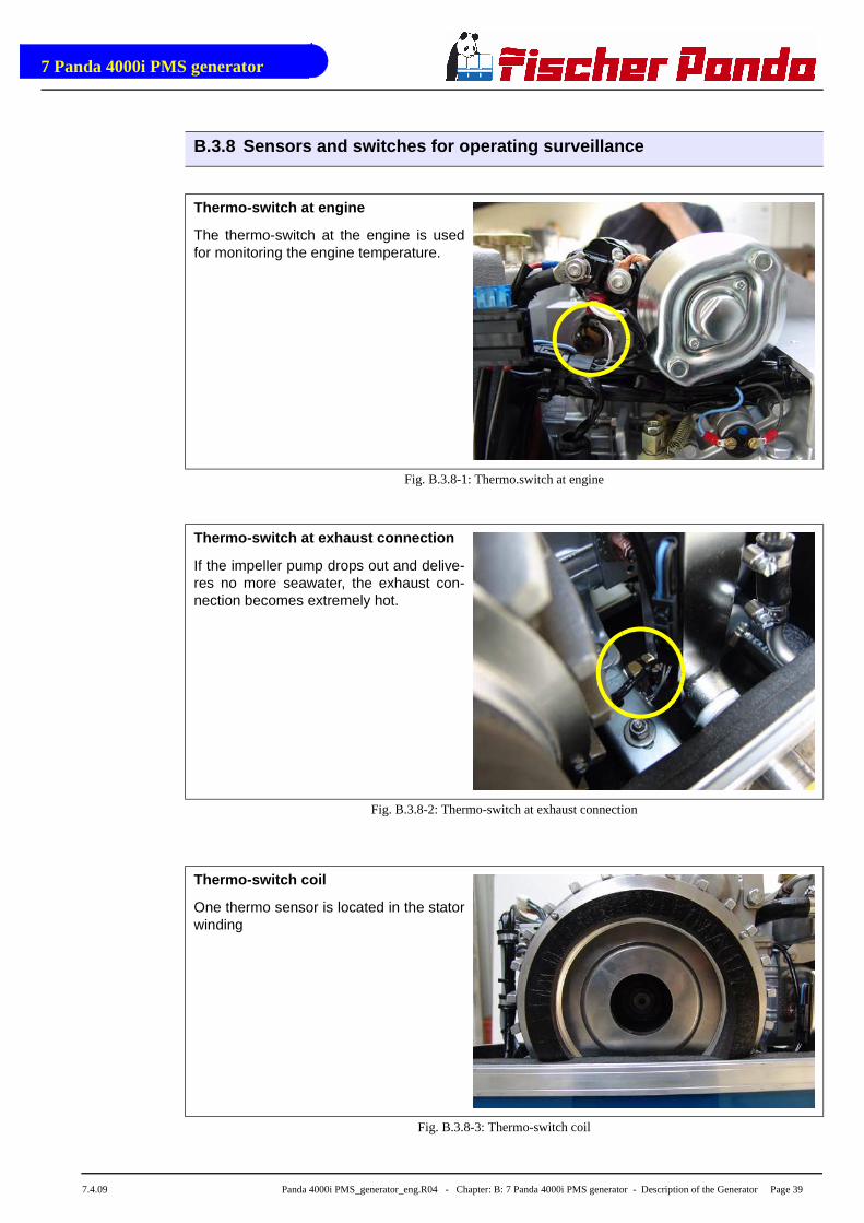
B.3.8 Sensors and switches for operating surveillanc e
Thermo-switch at engine
The thermo-switch at the engine is usedfor monitoring the engine temperature.
Fig. B.3.8-1: Thermo.switch at engine
Thermo-switch at exhaust connection
If the impeller pump drops out and delive-res no more seawater, the exhaust con-nection becomes extremely hot.
Fig. B.3.8-2: Thermo-switch at exhaust connection
Thermo-switch coil
One thermo sensor is located in the statorwinding
Fig. B.3.8-3: Thermo-switch coil
1
2
3

7 Panda 4000i PMS generator
Page 40 Panda 4000i PMS_generator_eng.R04 - Chapter: B: 7 Panda 4000i PMS generator - Description of the Generator 7.4.09
Oil pressure switch
In order to be able to monitore the lubrica-ting oil system, an oil pressure switch isbuilt into the system.
Fig. B.3.8-4: Oil pressure switch

7 Panda 4000i PMS generator
7.4.09 Panda 4000i PMS_generator_eng.R04 - Chapter: B: 7 Panda 4000i PMS generator Page 41
B.3.9 External Components
Panel iControl
Fig. B.3.9-1: iControl
Electronic board for iControl mounted at the genera -tor.
For description please see „Panel Manual“
Fig. B.3.9-2: Electronic board
PMGi 4000
The „inverter“ of the Panda 4000i
Fig. B.3.9-3: PMHGi 4000

7 Panda 4000i PMS generator
Page 42 Panda 4000i PMS_generator_eng.R04 - Chapter: B: 7 Panda 4000i PMS generator 7.4.09
B.4 Operation Instructions - see separate control pa nel manual
B.4.1 Daily routine checks before starting - See iCo ntrol manual.
B.4.2 Starting Generator - See iControl manual.
B.4.3 Stopping the Generator - See iControl manual.

Panda 4000i_Stellmotor_eng.fm Kapitel/ChapterA: - Seite/Page 1
Fischer Panda special equipmentA. Panda 4000i with optional actuator
A.1 Cleaning and replacement of parts at the generat or
The battery must always be disconnected, if work on the generator or electrical system isto be carried out, so that the generator cannot be unintentionally started.
Note the safety instruction in the generator manual .
Attention!!! Parts of the generator and the cooling water may be hot after operation!!!DANGER!!!
Seite/Page 2 - Kapitel/Chapter A: Panda 4000i_Stellmotor_eng.fm
Fischer Panda special equipment
A.2 General informations
These Instruction has additional information to the manual of the Generator.
Pay attention to these pages! This Instruction has a higher priority than the manual.
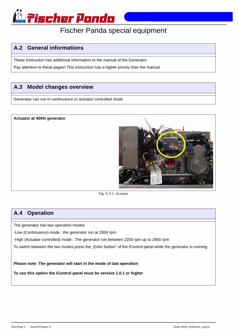
A.3 Model changes overview
Generator can run in continuance or actuator controlled mode
Actuator at 4000i generator
Fig. A.3-1: Actuator
A.4 Operation
The generator has two operation modes
-Low (Continuance) mode : the generator run at 2850 rpm
-High (Actuator controlled) mode : The generator run between 2200 rpm up to 2900 rpm
To switch between the two modes press the „Enter button“ of the iControl panel while the generator is running.
Please note: The generator will start in the mode o f last operation
To use this option the iControl panel must be versi on 1.0.1 or higher

Panda 4000i_Stellmotor_eng.fm Kapitel/ChapterA: - Seite/Page 3
A.4.1 Display in high mode
A.4.2 Display in low mode

Seite/Page 4 - Kapitel/Chapter A: Panda 4000i_Stellmotor_eng.fm
A.4.3 Actuator (sample picture)

Generator Installation Instructions
7.4.09 Panda 4000i PMS_generator_eng.R04 - Kapitel C: Generator Installation Instructions - Seite 43
C. Generator Installation Instructions
C.1 Placement
C.1.1 Placement and Basemount
Since Panda generators have extremely compact dimensions, they can be installed in tight locati-ons. Attempts are sometimes made to install them in almost inaccessible places. Please considerthat even almost maintenance-free machinery must still remain accessible at least at the front(drive belt, water pump) and the service-side (actuator, dipstick). Please also note that in spite ofthe automatic oil-pressure sensor it is still essential that the oil level has to be checked regularly.
C.1.2 Notice for optimal sound insulation
The generator should not be placed in the pro-ximity of light walls or floors, which can haveresonance vibrations because of airbornesounds. If this should be unavoidable, then it isrecommended that this surface is lined with 1mm lead foil, which will change the mass andthe vibration behaviour.
You should avoid fixing the generator on a slip-pery surface with little mass (i.e.). This acts asan amplifier of airborne sounds in the mostunreasonable case. An improvement can beachieved by reinforcing these surfaces withribs. In addition, the breakthroughs, whichinterrupt these surfaces, should be sawed off.The lining of the surrounding walls with aheavy layer (i.e lead) and foam additionally improve the conditions.
Fig. C.1.2-1: Convenient base
Generator Installation Instructions
Seite 44 Panda 4000i PMS_generator_eng.R04 - Kapitel C: Generator Installation Instructions 7.4.09
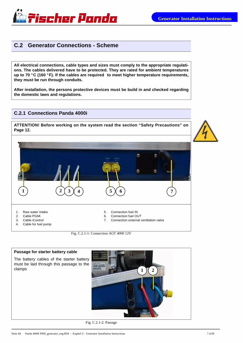
C.2 Generator Connections - Scheme
All electrical connections, cable types and sizes m ust comply to the appropriate regulati-ons. The cables delivered have to be protected. The y are rated for ambient temperaturesup to 70 ° C (160 ° F). If the cables are required to meet higher temperature requirements,they must be run through conduits.
After installation, the persons protective devices must be build in and checked regardingthe domestic laws and regulations.
C.2.1 Connections Panda 4000i
ATTENTION! Before working on the system read the se ction “Safety Precautions” onPage 12.
Fig. C.2.1-1: Connection AGT 4000 12V
Passage for starter battery cable
The battery cables of the starter batterymust be laid through this passage to theclamps
Fig. C.2.1-2: Passage
1 2 3 4 5 6 7
1. Raw water intake2. Cable PGMi3. Cable iControl4. Cable for fuel pump
5. Connection fuel IN6. Connection fuel OUT7. Connection external ventilation valve
1 2

Generator Installation Instructions
7.4.09 Panda 4000i PMS_generator_eng.R04 - Kapitel C: Generator Installation Instructions - Seite 45
C.3 Cooling System Installation - Raw water
C.3.1 General References
The generator should have its own raw water (coolant water) inlet and should not be connected toany other engine systems. Ensure that the following installation instructions are complied with:
Avoid galvanic corrosion
For the avoidance of galvanic corrosion the chapter "Service instruction for marine aggre-gates (corrosion protection)“ is to be considered.
C.3.2 Installation of the thru-vessel fitting in Yac hts
It is good practice for yachts to use a hull inlet fit-ting with an integrated strainer. The thru-vesselfitting (raw water intake) is often mounted againstthe sailing direction to induce more water intakefor cooling.
For Panda generators, the thru-vessel inletshould NOT point in the sailing direction! Whensailing at higher speeds more water will be forcedinto the inlet than what the pump can handle andyour generator will overflood!
Fig. C.3.2-1: Thru-vessel fitting
C.3.3 Quality of the raw water sucking in line
In order to keep the suction resistance in the line at a minimum, the raw water intake system (i.e.sea cock, thru-hull fitting, inlet filter, etc.) must have an inner diameter of at least 1" (25mm).
This applies also to installation components such as thru-hull fitting, sea cock, raw water filter etc.The intake suction line should be kept as short as possible. Install the raw water inlet in close pro-ximity to the genset.
After start-up the cooling water quantity must be m easured (e.g. by catching at theexhaust). The flow rate, as well as the necessary c ross section of the cooling water pipetake from Table 1, “Diameter of conduits,” on page 7 3.
Generator Installation Instructions
Seite 46 Panda 4000i PMS_generator_eng.R04 - Kapitel C: Generator Installation Instructions 7.4.09
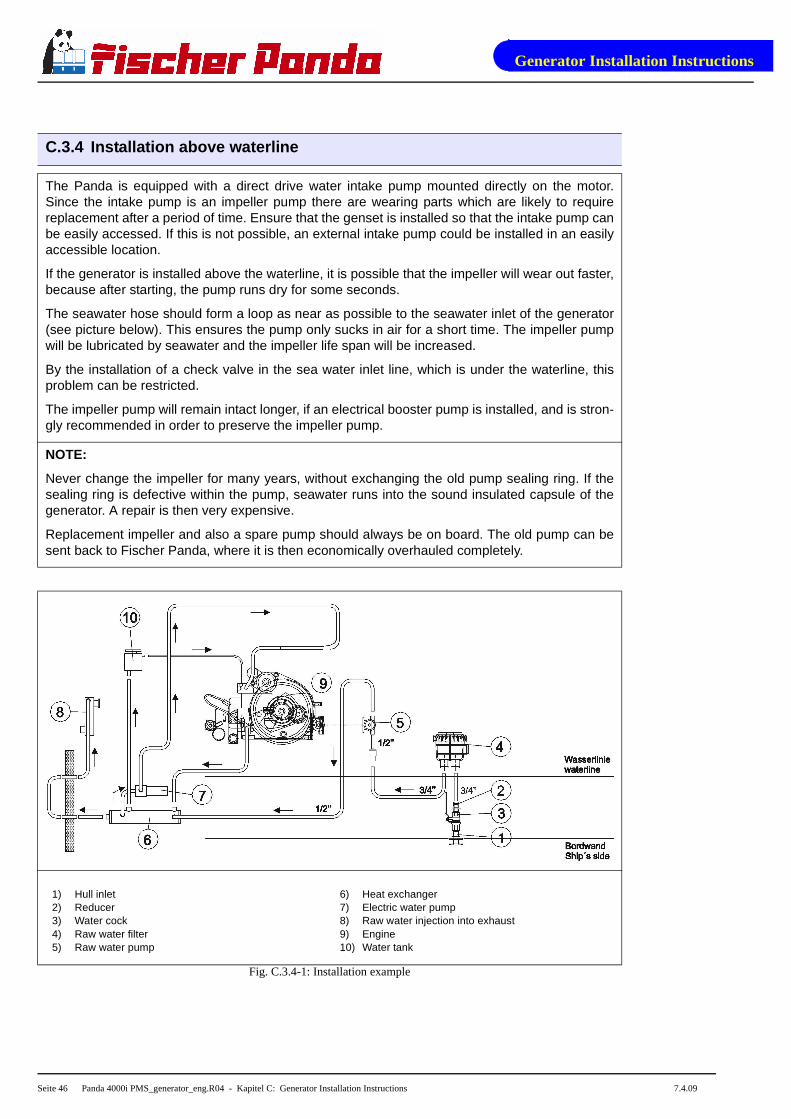
C.3.4 Installation above waterline
The Panda is equipped with a direct drive water intake pump mounted directly on the motor.Since the intake pump is an impeller pump there are wearing parts which are likely to requirereplacement after a period of time. Ensure that the genset is installed so that the intake pump canbe easily accessed. If this is not possible, an external intake pump could be installed in an easilyaccessible location.
If the generator is installed above the waterline, it is possible that the impeller will wear out faster,because after starting, the pump runs dry for some seconds.
The seawater hose should form a loop as near as possible to the seawater inlet of the generator(see picture below). This ensures the pump only sucks in air for a short time. The impeller pumpwill be lubricated by seawater and the impeller life span will be increased.
By the installation of a check valve in the sea water inlet line, which is under the waterline, thisproblem can be restricted.
The impeller pump will remain intact longer, if an electrical booster pump is installed, and is stron-gly recommended in order to preserve the impeller pump.
NOTE:
Never change the impeller for many years, without exchanging the old pump sealing ring. If thesealing ring is defective within the pump, seawater runs into the sound insulated capsule of thegenerator. A repair is then very expensive.
Replacement impeller and also a spare pump should always be on board. The old pump can besent back to Fischer Panda, where it is then economically overhauled completely.
Fig. C.3.4-1: Installation example
1) Hull inlet2) Reducer3) Water cock4) Raw water filter5) Raw water pump
6) Heat exchanger7) Electric water pump8) Raw water injection into exhaust9) Engine10) Water tank
Generator Installation Instructions
7.4.09 Panda 4000i PMS_generator_eng.R04 - Kapitel C: Generator Installation Instructions - Seite 47
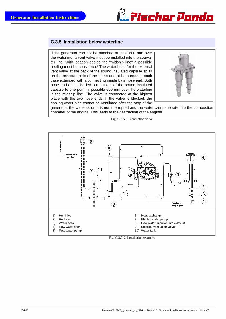
C.3.5 Installation below waterline
If the generator can not be attached at least 600 mm overthe waterline, a vent valve must be installed into the seawa-ter line. With location beside the "midship line" a possibleheeling must be considered! The water hose for the externalvent valve at the back of the sound insulated capsule splitson the pressure side of the pump and at both ends in eachcase extended with a connecting nipple by a hose end. Bothhose ends must be led out outside of the sound insulatedcapsule to one point, if possible 600 mm over the waterlinein the midship line. The valve is connected at the highestplace with the two hose ends. If the valve is blocked, thecooling water pipe cannot be ventilated after the stop of thegenerator, the water column is not interrupted and the water can penetrate into the combustionchamber of the engine. This leads to the destruction of the engine!
Fig. C.3.5-1: Ventilation valve
Fig. C.3.5-2: Installation example
1) Hull inlet2) Reducer3) Water cock4) Raw water filter5) Raw water pump
6) Heat exchanger7) Electric water pump8) Raw water injection into exhaust9) External ventilation valve10) Water tank
Generator Installation Instructions
Seite 48 Panda 4000i PMS_generator_eng.R04 - Kapitel C: Generator Installation Instructions 7.4.09
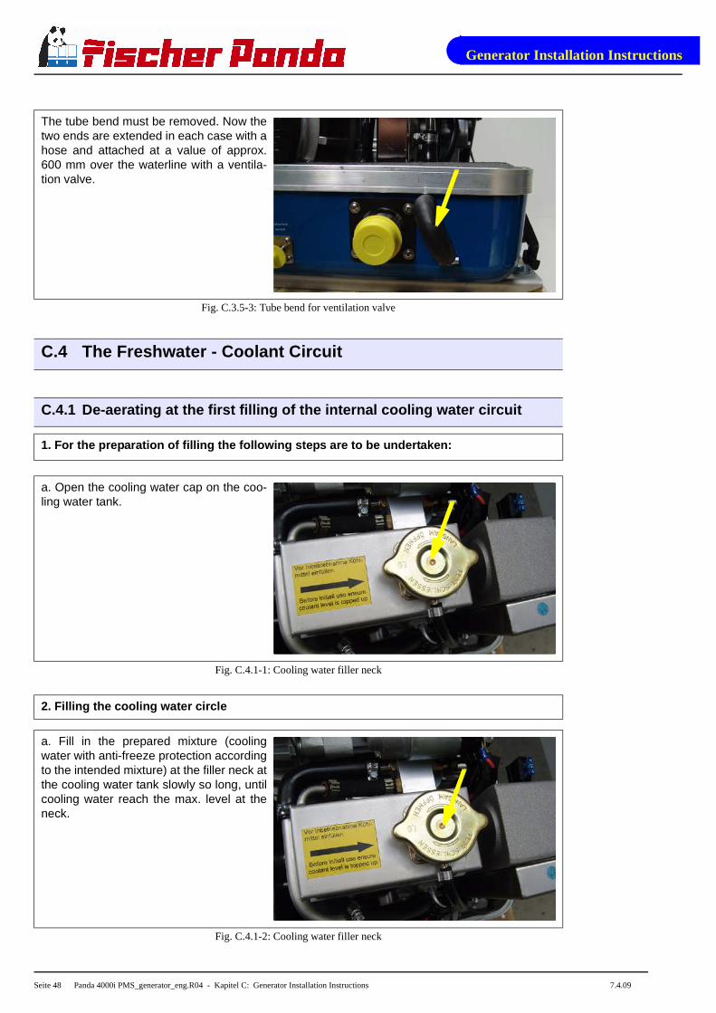
The tube bend must be removed. Now thetwo ends are extended in each case with ahose and attached at a value of approx.600 mm over the waterline with a ventila-tion valve.
Fig. C.3.5-3: Tube bend for ventilation valve
C.4 The Freshwater - Coolant Circuit
C.4.1 De-aerating at the first filling of the intern al cooling water circuit
1. For the preparation of filling the following ste ps are to be undertaken:
a. Open the cooling water cap on the coo-ling water tank.
Fig. C.4.1-1: Cooling water filler neck
2. Filling the cooling water circle
a. Fill in the prepared mixture (coolingwater with anti-freeze protection accordingto the intended mixture) at the filler neck atthe cooling water tank slowly so long, untilcooling water reach the max. level at theneck.
Fig. C.4.1-2: Cooling water filler neck

Generator Installation Instructions
7.4.09 Panda 4000i PMS_generator_eng.R04 - Kapitel C: Generator Installation Instructions - Seite 49
Anti-freeze
In the interest of safety, the freezing point of the closed circuit coolant should be checked on aregular basis . Be sure that the coolant/antifreeze mixture is good for at least -15°C (5°F) and if itis possible that your genset experiences lower temperatures, for example during storage or trans-portation, then the entire cooling system should be drained and purged. To purge the coolingsystem, compressed air at about 0.5 bar (7.5 psi) is sufficient.
Electric cooling water pump
Connect the cooling water pump to an external 12 V power supply and start the pump. Refill thethe cooling water at the filler neck while the pump runs.
3. De-aerating
The cooling water circuit of the generator is self de-aerating.
ATTENTION! During the de-aerating process it must b e checked again and again if thecooling water is indeed circulating. If air bubbles established in the internal cooling waterpump, it could be, that the cooling water circuit i s not circulate. Then the generator wouldbe warming very fast and switched off by overheatin g.
C.5 Watercooled Exhaust System
By injecting the outlet raw water into the exhaust manifold, the exhaust gases are cooled and thenoise emissions from the exhaust system are reduced.
C.5.1 Installation of the standard exhaust system
The generator exhaust system must remain completely independent and separate from theexhaust system of any other unit(s) on board. The exhaust hose has an inner diameter of 40 mm(1.6") (Panda 14000 and above approx. 50 mm). The water lock must be installed at the lowestpoint of the exhaust system. An optional noise insulated water lock can also be installed. Theexhaust hose descends from the capsule to the water lock. Then the hose rises via the "gooseneck" to the silencer (see drawing). The goose neck must be vertical and sit preferably along theship's keel centre line. The exhaust system must be installed so that the back pressure inside theexhaust does not exceed 0.4 bar (6 psi) and total length does not exceed 6 m (20 ft.).
Exhaust diameter see “Diameter of conduits” on Page 73.
Generator Installation Instructions
Seite 50 Panda 4000i PMS_generator_eng.R04 - Kapitel C: Generator Installation Instructions 7.4.09
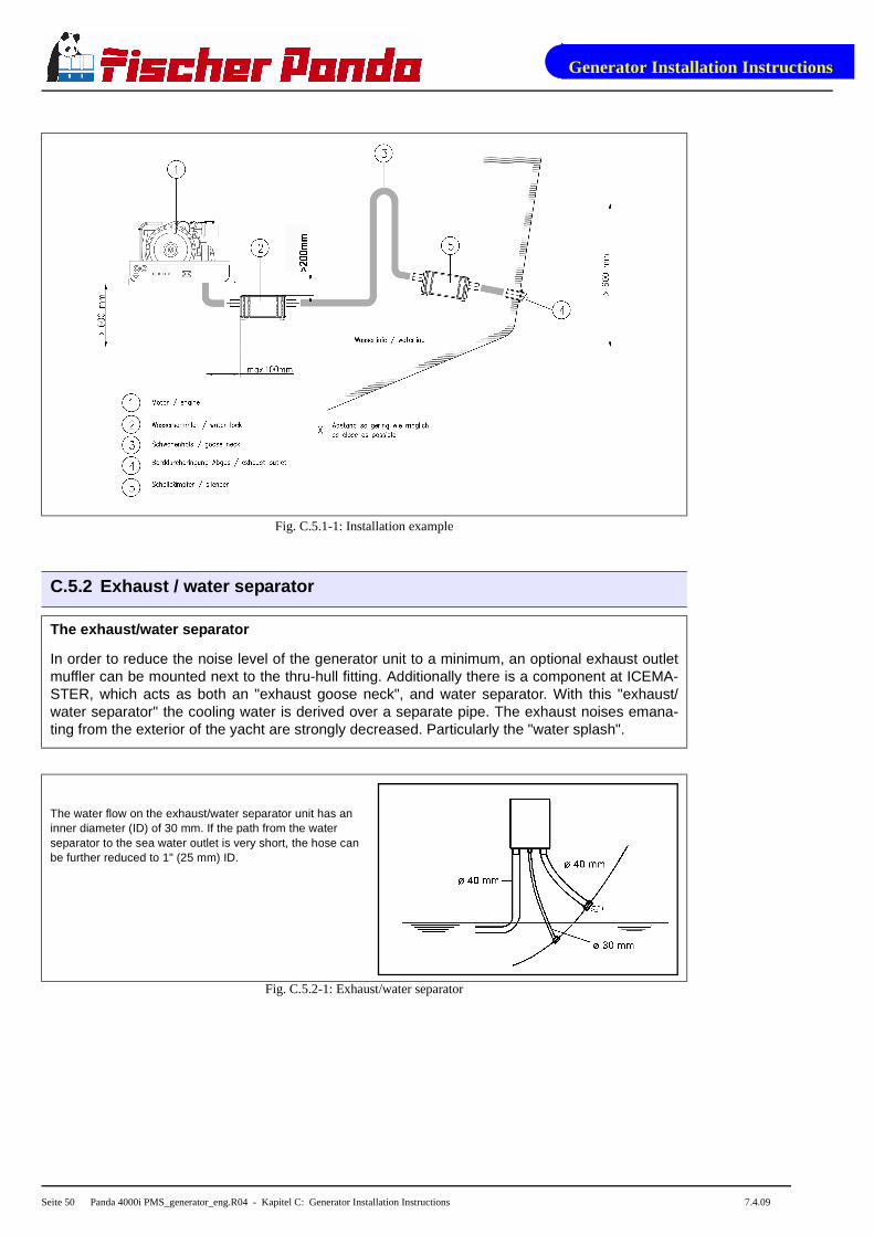
Fig. C.5.1-1: Installation example
C.5.2 Exhaust / water separator
The exhaust/water separator
In order to reduce the noise level of the generator unit to a minimum, an optional exhaust outletmuffler can be mounted next to the thru-hull fitting. Additionally there is a component at ICEMA-STER, which acts as both an "exhaust goose neck", and water separator. With this "exhaust/water separator" the cooling water is derived over a separate pipe. The exhaust noises emana-ting from the exterior of the yacht are strongly decreased. Particularly the "water splash".
The water flow on the exhaust/water separator unit has an inner diameter (ID) of 30 mm. If the path from the water separator to the sea water outlet is very short, the hose can be further reduced to 1" (25 mm) ID.
Fig. C.5.2-1: Exhaust/water separator
Generator Installation Instructions
7.4.09 Panda 4000i PMS_generator_eng.R04 - Kapitel C: Generator Installation Instructions - Seite 51
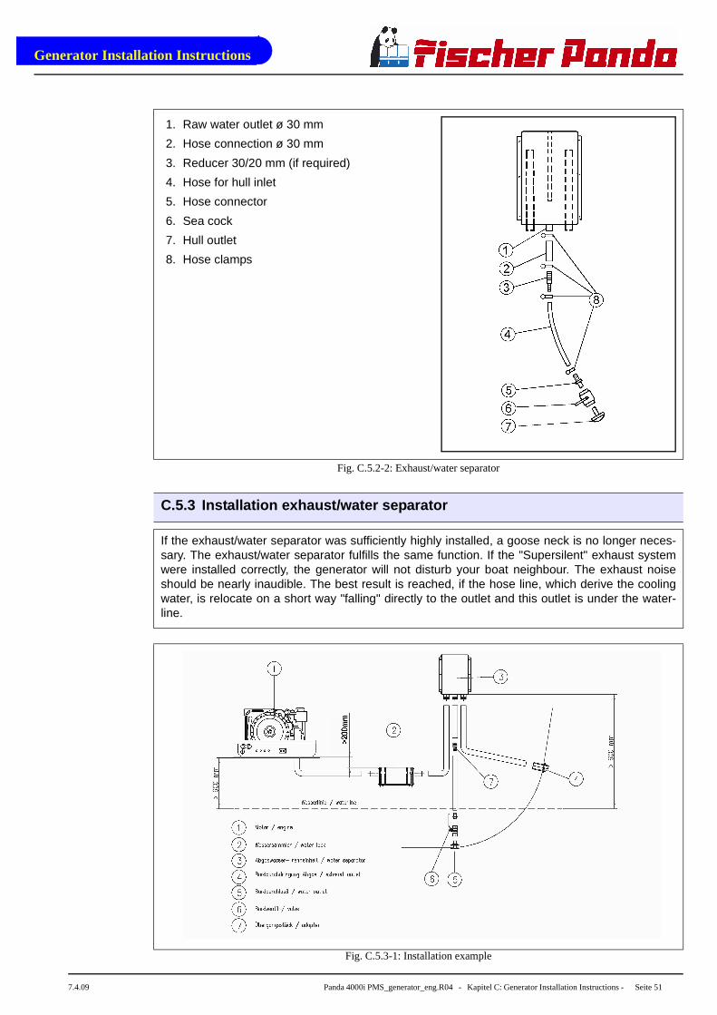
Fig. C.5.2-2: Exhaust/water separator
C.5.3 Installation exhaust/water separator
If the exhaust/water separator was sufficiently highly installed, a goose neck is no longer neces-sary. The exhaust/water separator fulfills the same function. If the "Supersilent" exhaust systemwere installed correctly, the generator will not disturb your boat neighbour. The exhaust noiseshould be nearly inaudible. The best result is reached, if the hose line, which derive the coolingwater, is relocate on a short way "falling" directly to the outlet and this outlet is under the water-line.
Fig. C.5.3-1: Installation example
1. Raw water outlet ø 30 mm
2. Hose connection ø 30 mm
3. Reducer 30/20 mm (if required)
4. Hose for hull inlet
5. Hose connector
6. Sea cock
7. Hull outlet
8. Hose clamps
Generator Installation Instructions
Seite 52 Panda 4000i PMS_generator_eng.R04 - Kapitel C: Generator Installation Instructions 7.4.09
If the thru-hull exhaust outlet has to be mounted far from the generator, an exhaust-water separa-tor must definitely be installed. The sea water from the separator must then run along the shortestpossible path is the thru-hull outlet. For such long exhaust routes, the exhaust hose diametershould also be increased from NW 40 mm to NW 50 mm in order to reduce the back-pressure.The exhaust may have a length of over 10 m (32 ft.), if the exhaust hose diameter is increased to50 mm. An additional outlet exhaust muffler close to the hull outlet will help further to reducenoise emissions.
C.6 Fuel System Installation
C.6.1 General References
Additionally to the standard fine filter a pre-filter with water separator must be installed outside ofthe sound insulation capsule in easily accessible places in the fuel system line between the tankintake fuel pump and the diesel motor´s fuel pump (is not included in the delivery).
The forward and return fuel flow pipes must be connected to the diesel tank. Do not conenct thegenerator fuel supply lines with any other fuel lines in other diesel systems.
The following items need to be installed:
• Fuel supply pump (12V-DC)
• Pre-filter with water separator (not part of the delivery)
• Fine particle fuel filter
• Return fuel line to fuel tank (unpressurized)
The fuel supply pump should be installed to the fuel tank as close as possible. The electric cablefor the fuel pump is already installed at the generator (length 5 m).

Generator Installation Instructions
7.4.09 Panda 4000i PMS_generator_eng.R04 - Kapitel C: Generator Installation Instructions - Seite 53
Fig. C.6.1-1: Example for fuel installation
C.6.2 The electrical fuel pump
Electrical fuel pump
With the Panda generator is usually supp-lied an external, electrical fuel pump (12 VDC). The fuel pump must be installedclose to the fuel tank. The electrical con-nections with the provided cable (5 m) arepre-installed.
Fig. C.6.2-1: Electrical fuel pump
• Suction hight of the pump: max. 1,2 m at 02, bar
• Diameter of fuel lines: “Diameter of conduits” on Page 73
1 2 3 4 5
8
7
6
1. Generator2. Fuel stop cock3. Fuel filter4. Fuel return pipe
5. Condensation water suction pump6. Fuel tank7. Fuel supply pipe8. Electrical fuel pump (12V-DC)
Generator Installation Instructions
Seite 54 Panda 4000i PMS_generator_eng.R04 - Kapitel C: Generator Installation Instructions 7.4.09
C.6.3 Connection of the fuel lines at the tank
Lead the return fuel pipe connected to the day tank to the floor
The return pipe connected to the tank must be dropped to the same depth as the suction pipe, ifthe generator is mounted higher than the tank, in order to prevent fuel running back into the tankafter the motor has been switched off, which can lead to enormous problems, if the generator isswitched off for a long period.
Non-return Valve in the Suction Pipe
A non-return valve must be fitted to the suction pipe, which prevents the fuel flowing back afterthe generator has been switched off, if it is not possible to use the return flow pipe as a submergepipe placed in the tank. The instructions "Bleeding Air from the Fuel System" must be read afterinitial operation or after it has stood still for a long period, in order to preserve the starter battery.
ATTENTION! Non-return valve for the fuel return pip e
If the fuel tank should be installed over the level of the generator (e.g. daily tank), then anon-return valve must be installed into the fuel re turn pipe to guarantee that through thereturn pipe no fuel is led into the injection pump.
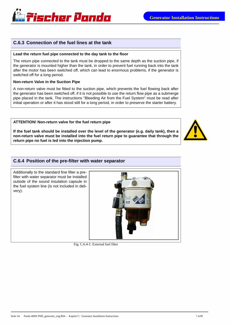
C.6.4 Position of the pre-filter with water separato r
Additionally to the standard fine filter a pre-filter with water separator must be installedoutside of the sound insulation capsule inthe fuel system line (is not included in deli-very).
Fig. C.6.4-1: External fuel filter

Generator Installation Instructions
7.4.09 Panda 4000i PMS_generator_eng.R04 - Kapitel C: Generator Installation Instructions - Seite 55
C.7 Generator DC System-Installation
C.7.1 Connection of the 12 V starter battery
The positive (+) battery cable is connecteddirecly to the solenoid switch of the startermotor.
Fig. C.7.1-1: Connection starter battery
The negative (-) battery cable is connec-ted to the engine.
Fig. C.7.1-2: Connection starter battery

Generator Installation Instructions
Seite 56 Panda 4000i PMS_generator_eng.R04 - Kapitel C: Generator Installation Instructions 7.4.09
C.7.2 Fuse
F1: Fuse 30 A for DC system
Fig. C.7.2-1: Terminal block AGT 4000 12V
C.7.3 Installation of the iControl panel - See iCont rol Manual
C.8 Generator Electric-System-Installation
ATTENTION! Before the electrical system is installe d, READ the “Safety Precautions” onPage 12 of this manual FIRST! Be sure that all elect rical installations (including all safetysystems) comply with all required regulations of th e regional authorities. This includeslightnening conductor, personal protection switch e tc.
All electrical safety installations have to be made on board.
Required cable cross-sections
The following recommended electrical cable dimensions (cross sections) are the minimum requi-red sizes for a safe installation (see “nominal wire cross-section” on Page 73).
F1
Generator Failure
7.4.09 Panda 4000i PMS_generator_eng.R04 - Kapitel D: Generator Failure - Seite 57
D. Generator Failure
D.1 Tools and measuring instruments
In order to be able to manage disturbances while dr iving, following tools and measuringinstruments should belong to the equipment on board :
• Multimeter for voltage (AC), frequency and resistance
• Measuring instrument for inductance
• Measuring instrument for capacity
• Current absorbing clamps
• Thermometer (ideal is a infrared thermometer)
• Pressure device (pincer) für coolant circuit
D.2 Overloading the Generator
Please ensure that the genset is not overloaded. Overloading occurs when the electrical load(demand) induces a load torque in the generator which is higher than that which the diesel drivemotor can provide. Overloading causes the engine to run rough, burn oil, creates excessiveexhaust (environmentally unfriendly) and even to stall. Extra caution should be practised withmulti-power units (single and 3-phase current generation) to avoid overloading the diesel driveengine.
The generator should only be loaded at the peak rated power for short periods only! A high peakcurrent is required to start many electrical devices, especially electric motors and compressors(from a still stand state).
In order to prolong the genset´s life expectancy, the nominal electrical demand on the systemshould not be more than 70% of the rated genset peak load.
Keep PEAK LOADING demand in mind when switching on electrical devices (esp. fridge com-pressors, electric motors, battery chargers, kettles, etc.) which are fed by the generator. Careful"powering up" (gradual loading) of the electrical demand on the generator will help prolong the lifeof your genset! The genset can be run for several hours at partial load (i.e. 2/3 of rated power),however it is not advised that it is run for more than 2-3 hours at full load. The Panda is designedso as not to overheat even under extreme conditions. Note: The exhaust gas will become sootyduring peak-load operation.
Effects of Short Circuiting and Overloading on the Generator
The generator cannot be damaged by short circuiting or overloading. Short circuiting and over-loading suppress the magnetic excitation of the generator, thus, no current is generated and thevoltage will collapse. This condition is immediately offset once the short-circuit has been elimina-ted and/or the electrical overload removed.
Generator Failure
Seite 58 Panda 4000i PMS_generator_eng.R04 - Kapitel D: Generator Failure 7.4.09
D.2.1 Low Generator-Output Voltage
ATTENTION! Before working on the System read the se ction “Safety Precautions” onPage 12.
If the produced alternating voltage is too low, switch the load off, in order to relieve the generator.Mostly the problem already solved. If the output voltage is still too low, even if all load is switchedoff, the generator runs without load, you can assume one or more condensers are defective.
D.3 Starting Problems
D.3.1 De-aerating the fuel system
Normally, the fuel system is designed to bleed out air itself i.e. as soon as the electric startermotor starts operation the fuel pump starts working and the fuel system will be de-aerated aftersome time automatically. It is nevertheless essential to bleed the system as follows prior to thefirst operation (as all hoses are empty):
1. Put a container under the fuel return pipe to catch running out fuel to catch.
2. Take off the plug at the solenoid of the starter motor.
3. Switch the panel „ON“.
4. Press „START“-button. The fuel pump runs audible.
5. Switch the panel „OFF“.
6. Switch the panel „ON“.
7. Press again the „START“-button.
This procedure must be repeated several times, unti l fuel (nonporously) withdraws per-fectly at the fuel return pipe.
8. Switch the panel „OFF“.
9. Attach the plug at the solenoid of the starter motor.
D.3.2 Fuel Solenoid Valve
For start problems the possibility of an error exists with the solenoid for engine stop or fuel sole-noid valve, which both effect affect simultaneous on the fuel system.
The fuel solenoid valve is located in front of the injection pump. It opens automatically, if the"START"-button is pressed on the remote control panel. The solenoid valve is CLOSED when thegenerator main power is switched "OFF". For this reason, it requires a few seconds before themotor comes to a full halt.
If the generator fails to start, runs rough, does not reach the proper RPM, or does not stop pro-perly, the first item to suspect in most cases is the fuel solenoid valve and should be inspectedfirst.
A check of the fuel solenoid valve by removing the plug from the fuel solenoid valve for a shortperiod whilst in operation (first remove the small retention screw) and replace it immediately. Themotor should "react immediately" by revving high.If the motor does not react sharply to the recon-nection of the solenoid wire, it is a sign that the solenoid valve could be faulty.

Generator Failure
7.4.09 Panda 4000i PMS_generator_eng.R04 - Kapitel D: Generator Failure - Seite 59
Fuel solenoid valve
Fig. D.3-1: Fuel solenoid valve
D.4 Troubleshooting Table
For troubleshooting see “Trouble shooting” on Page 74.

Generator Failure
Seite 60 Panda 4000i PMS_generator_eng.R04 - Kapitel D: Generator Failure 7.4.09

Generator Maintenance Instructions
7.4.09 Panda 4000i PMS_generator_eng.R04 - Kapitel E: Generator Maintenance Instructions - Seite 61
E. Generator Maintenance Instructions
E.1 General maintenance instructions
E.1.1 Checks before starting
• Oil level
• Cooling system leaks
• Visual check for any changes, leaks oil drain system, v-belt, cable connections, hose clips, air filter, fuel lines
Maintenance see Table F.4, “Inspection checklist fo r services,” on Page 78.
E.1.2 Hose elements and rubber formed component in t he sound cover
Check all hoses and hose connections for good condition. The rubber hoses are very sensitive toenviromental influences. They can season fast with dry air, in which environment of muted oil andfuel steams and increased temperature. The hoses must be checked regularly for elasticity.There are operating situations, at which the hoses must be renewed once in the year.
Additionally to usual tasks of maintenance (oil level check, oil filter control etc.) further mainte-nance activities are to be accomplished for marine aggregates.
E.2 Oil circuit maintenance
The first oil change is to be accomplished after a period of operation from 35 to 50 hours. After-wards the oil is to be changed after 100 hours. For this the oil SAE30 for temperatures over 20°Cand SAE20 for temperatures between 5°C and 20°C is to be used. At temperatures under 5°C oilof the viscosity SAE10W or 10W-30 is prescribed.
Type and amount of required oil see:Table F.5, “Engine oil,” on Page 79 and Table F.2, “TechnicalData Engine,” on Page 77.

Generator Maintenance Instructions
Seite 62 Panda 4000i PMS_generator_eng.R04 - Kapitel E: Generator Maintenance Instructions 7.4.09
E.3 Execution of an oil change
Oil drain hose
For the oil change an oil drain hose is leadthrough the sound cover.
Fig. E.3-1: Oil drain hose
Oil drain screw
The oil can be discharged by opening theoil drain screw. For countering use asecond wrench.
Fig. E.3-2: Oil drain screw
Oil drain pump
If discharging of the oil is not possible, werecommend the employment of a handpump, which can be attached to the oildrain hose.
Afterwards the oil drain screw is closedagain.
Fig. E.3-3: Oil drain pump
17
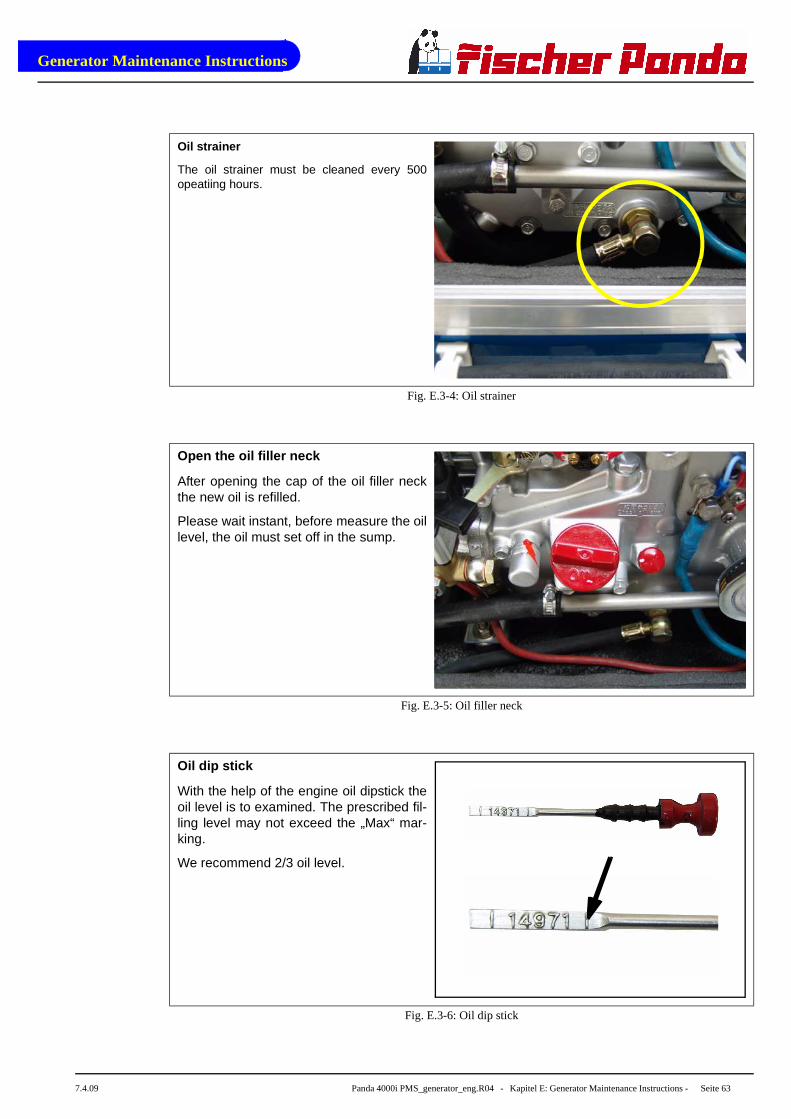
Generator Maintenance Instructions
7.4.09 Panda 4000i PMS_generator_eng.R04 - Kapitel E: Generator Maintenance Instructions - Seite 63
Oil strainer
The oil strainer must be cleaned every 500opeatiing hours.
Fig. E.3-4: Oil strainer
Open the oil filler neck
After opening the cap of the oil filler neckthe new oil is refilled.
Please wait instant, before measure the oillevel, the oil must set off in the sump.
Fig. E.3-5: Oil filler neck
Oil dip stick
With the help of the engine oil dipstick theoil level is to examined. The prescribed fil-ling level may not exceed the „Max“ mar-king.
We recommend 2/3 oil level.
Fig. E.3-6: Oil dip stick

Generator Maintenance Instructions
Seite 64 Panda 4000i PMS_generator_eng.R04 - Kapitel E: Generator Maintenance Instructions 7.4.09
E.4 Checking the water separator in the fuel supply
The pre-filter with water separator has acock at its lower surface, with this cock thedownward sunk water can be discharged.
This is simply possible, water is heavierdue to its density than the Diesel.
Fig. E.4-1: External fuel filter
E.4.1 De-aerating the fuel system
Normally, the fuel system is designed to bleed out air itself i.e. as soon as the electric startermotor starts operation the fuel pump starts working and the fuel system will be de-aerated aftersome time automatically. It is nevertheless essential to bleed the system as follows prior to thefirst operation (as all hoses are empty):
1. Put a container under the fuel returnpipe to catch running out fuel to catch.
Fig. E.4.1-1: Fuel return pippe

Generator Maintenance Instructions
7.4.09 Panda 4000i PMS_generator_eng.R04 - Kapitel E: Generator Maintenance Instructions - Seite 65
2. Take off the plug at the solenoid of thestarter motor.
Fig. E.4.1-2: Starter motor
3. Switch the panel „ON“.
4. Press „START“-button. The fuel pumpruns audible.
5. Switch the panel „OFF“.
6. Switch the panel „ON“.
7. Press again the „START“-button.
This procedure must be repeatedseveral times, until fuel (nonporously)withdraws perfectly at the fuel returnpipe.
8. Switch the panel „OFF“.
9. Attach the plug at the solenoid of thestarter motor.
Fig. E.4.1-3: iControl

Generator Maintenance Instructions
Seite 66 Panda 4000i PMS_generator_eng.R04 - Kapitel E: Generator Maintenance Instructions 7.4.09
E.4.2 Replacement of the air filter
Open the air suctin housing by loosen thesix hexagon head screws on the framecover.
Fig. E.4.2-1: Air filter
Change the air filter mat and close thecover again.
Fig. E.4.2-2: Air filter mat
8

Generator Maintenance Instructions
7.4.09 Panda 4000i PMS_generator_eng.R04 - Kapitel E: Generator Maintenance Instructions - Seite 67
E.5 De-aerating of the coolant circuit / freshwater
The Panda 4000i PMS is self de-aerating.
E.6 The raw water circuit
E.6.1 Clean raw water filter
The raw water filter should be released regularlyfrom arrears. In each case the water cock mustbe closed before. It is mostly sufficient to beatthe filter punnet.
If water should seep through the cover of the rawwater filter, this may be sealed in no case withadhesive or sealant. Rather must be searchedfor the cause for the leakage. In the simplestcase the sealing ring between caps and filter hol-ders must be exchanged.
Fig. E.6.1-1: Raw water filter

Generator Maintenance Instructions
Seite 68 Panda 4000i PMS_generator_eng.R04 - Kapitel E: Generator Maintenance Instructions 7.4.09
E.6.2 Causes with frequent impeller waste
The impeller of the cooling water pump must be regarded as wearing part. The life span of theimpeller can be extremely different and exclusively depends on the operating conditions. Thecooling water pumps of the PANDA generators are laid out in such a way that the number of revo-lutions of the pump lies low compared with other aggregates. This is for the life span of the pumpa positive effect.
Unfavorably affects the life span of the impeller, if the cooling water sucking in way is relativelylong or the supply is handicapped, so that the cooling water sucking in range develops a negativepressure. This can reduce first of all the power of the cooling water pump extremely that thewings of the impeller are exposed to very strong loads. This can shorten the life span extremely.
Further the operation of the impeller pump loaded in waters with a high portion of suspended mat-ters. The use of the impeller pump is particularly critical in coral waterbodies. Cases are well-known, which a impeller pump had so strongly run after 100 hours already that the lip seal on thewave was ground in. In these cases sharp crystal parts of the coral sand assess in the rubberseal and affect like an abrasive the high-grade steel shank of the impeller pump.
If the generator were mounted over the water level it is particularly unfavorable for the impellerpump. After the first start some seconds will pass by, until the impeller can suck in cooling water.This short unlubricated operation time damages the impeller. The increased wear can lead aftershort time to the loss. (see special notes: "Effects on the impeller pump, if the generator is moun-ted over the waterline").
E.6.3 Replacement of the impeller
Close the raw water stop cock.
Fig. E.6.3-1: Raw water stop cock

Generator Maintenance Instructions
7.4.09 Panda 4000i PMS_generator_eng.R04 - Kapitel E: Generator Maintenance Instructions - Seite 69
Raw water pump on the front side of thegenset.
Fig. E.6.3-2: Raw water pump
Remove the cover of the raw water pumpby loosen the wing screws from the hou-sing.
Fig. E.6.3-3: Raw water pump
Pull to the impeller with a multigrip pliers ofthe wave.
Mark the impeller, to make sure that theseis used in the correct position at re-instal-lation.
Fig. E.6.3-4: Impeller

Generator Maintenance Instructions
Seite 70 Panda 4000i PMS_generator_eng.R04 - Kapitel E: Generator Maintenance Instructions 7.4.09
Check to the impeller for damage andreplace it if necessary.
Before the reinsertion into the housing theimpeller should have been lubricated withglycerin or with a non-mineral oil basedlubricant e.g. silicone spray.
Fig. E.6.3-5: Impeller
The impeller is attached to the pump wave(if the old impeller is used, pay attention tothe before attached marking).
Fastening the cover and use a new seal.
Fig. E.6.3-6: Impeller seal
Remind the customer
• to run the generator only with closed capsule.
• not to run the generator unattended
• to ask for regular service

Generator Maintenance Instructions
7.4.09 Panda 4000i PMS_generator_eng.R04 - Kapitel E: Generator Maintenance Instructions - Seite 71
E.7 Conservation at longer operation interruption
E.7.1 Measures on preparation of the winter storage
1. Rinse raw water circuit with an anti-freeze solution, even if this contains a corrosion protectionmeans. The raw water inlet must be removed at the water cock. Over a hose connector theanti-freeze protection mixture is to be sucked in from a container. The leaked cooling waterwith the exhaust is to be led back into the sucking in container. The circuit must be kept uprightsome minutes to guaranteed that the anti-freeze protection mixture reaches all ranges of thecooling system.
2. The concentration of the anti-freeze mixture in the internal cooling circuit must be checkedwith a suitable measuring instrument. The concentration must be furnished according to thelowest temperatures which can be expected.
3. Clean raw water filter and check seal.
4. Check water cock for practicability. And spray with a corrosion protection oil from the inside orlubricate with acidless grease.
5. Check all hoses and hose connectors for good condition. The rubber hoses are very sensitiveto enviromental influences. They can age fast with dry air, in environment of light oil and fuelsteams and increased temperature. The hoses must be checked regularly for elasticity. Thereare operating situations, which the hoses must be renewed once in the year.
6. Check the hose connectors at all raw water valves doubly and if possible protect them withdouble hose clamps.
7. Dismount the impeller of the cooling water pump and check for wear. The impeller may notremain in the pump. It must be greased with vaseline and be kept at a dark place. It can bereintragrated in the spring again into the pump, if it is in good condition. The impeller is a wea-ring part, it is recommended to renew it always in the spring, independently how many opera-ting hours the aggregate ran.
8. Control of the vent valve at the raw water inlet. If the generator is installed below the waterline,always a vent valve is necessary. The vent valve must be checked also during the seasonregularly. In the winter storage the vent valve should always be disassembled, checked andgreased. Hardens or got parts dirty are to be replaced.
9. Check water lock: If the generator were rinsed with an anti-freeze mixture, the antifreeze mix-ture can leave in the water lock. If the generator were rinsed with fresh water, the water in thewater lock must be drained. Otherwise the danger exists that the collector is blown up anddestroyed by ice.
10.Check the exhaust/water separator on leakage and if the hose connectors at the lower surfaceof the separation unit are in normal condition. (with extremely sulfureous fuels it is possiblethat also high-grade steel tube ends are attacked.)
11.Check all construction units at the generator inside the sound cover for leakages. If there aretraces of humidity in the sound cover, the cover must be dried. Further the cause for the wet-ness must be surched and eliminated.
12.During the winter storage the upper section of the sound cover must be taken off, in order toavoid condensed moisture formation, if traces of humidity remain in the sound cover insidecasing by leakages in the raw water circuit.
Generator Maintenance Instructions
Seite 72 Panda 4000i PMS_generator_eng.R04 - Kapitel E: Generator Maintenance Instructions 7.4.09
13.The generator housing and the housing of the engine should be sprayed with a corrosion pro-tection oil before the winter storage. This procedure is recommended also in the season. Thisprocedure can avoid that arising and humidity marks on the surface of the aluminum construc-tion units be noticed too late.
14.Disconnect the starter battery (positive and negative pole).
15.Lubricate the spindle for the number of revolutions adjustment device with a special lubricant(Antiseize grease).
16.Use of a air dehumidifier. The best way to protect a yacht in the winter storage againstdamage by humidity is, to places a air dehumidifier inside the ship and locks all hatches. Thedevices have a hygrometer, which switches the device off, if the humidity is under the adjustedvalue. There is no better method, in order to protect pads, cable, electronics, wood, enginesetc. optimally against any rotting by humidity.
E.7.2 Initiation at spring
• Before the first start turn the engine once with the hand, in order to eliminate necessary existing corrosion beginnings in the bushing. If necessarily carry out normal engine inspection.
• Change engine oil and engine oil filters.
• Reintegrate the impeller of the cooling water pump and check pump for leakage.
• Charge starter battery of the generator, connect cables and check battery voltage.
• Start generator and check the basic adjustments of the generator such as voltage, speed re-gulation etc..
• Check all switching off devices for function by operational procedures.
Fischer Panda does not take over adhesion for possi ble damages!
E.7.1 Measures on preparation of the winter storage
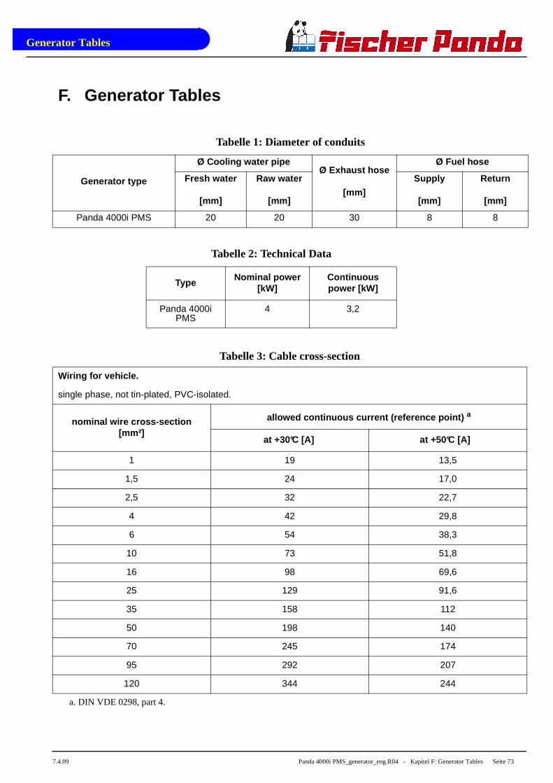
Generator Tables
7.4.09 Panda 4000i PMS_generator_eng.R04 - Kapitel F: Generator Tables Seite 73
F. Generator Tables
Tabelle 1: Diameter of conduits
Generator type
Ø Cooling water pipeØ Exhaust hose
[mm]
Ø Fuel hose
Fresh water
[mm]
Raw water
[mm]
Supply
[mm]
Return
[mm]
Panda 4000i PMS 20 20 30 8 8
Tabelle 2: Technical Data
TypeNominal power
[kW]Continuous power [kW]
Panda 4000i PMS
4 3,2
Tabelle 3: Cable cross-section
Wiring for vehicle.
single phase, not tin-plated, PVC-isolated.
nominal wire cross-section[mm²]
allowed continuous current (reference point) a
at +30°C [A] at +50°C [A]
1 19 13,5
1,5 24 17,0
2,5 32 22,7
4 42 29,8
6 54 38,3
10 73 51,8
16 98 69,6
25 129 91,6
35 158 112
50 198 140
70 245 174
95 292 207
120 344 244
a. DIN VDE 0298, part 4.
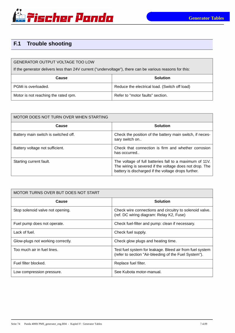
Generator Tables
Seite 74 Panda 4000i PMS_generator_eng.R04 - Kapitel F: Generator Tables 7.4.09
F.1 Trouble shooting
GENERATOR OUTPUT VOLTAGE TOO LOW
If the generator delivers less than 24V current ("undervoltage"), there can be various reasons for this:
Cause Solution
PGMi is overloaded. Reduce the electrical load. (Switch off load)
Motor is not reaching the rated rpm. Refer to "motor faults" section.
MOTOR DOES NOT TURN OVER WHEN STARTING
Cause Solution
Battery main switch is switched off. Check the position of the battery main switch, if neces-sary switch on..
Battery voltage not sufficient. Check that connection is firm and whether corrosionhas occurred..
Starting current fault. The voltage of full batteries fall to a maximum of 11V.The wiring is severed if the voltage does not drop. Thebattery is discharged if the voltage drops further.
MOTOR TURNS OVER BUT DOES NOT START
Cause Solution
Stop solenoid valve not opening. Check wire connections and circuitry to solenoid valve.(ref. DC wiring diagram: Relay K2, Fuse)
Fuel pump does not operate. Check fuel-filter and pump: clean if necessary.
Lack of fuel. Check fuel supply.
Glow-plugs not working correctly. Check glow plugs and heating time.
Too much air in fuel lines. Test fuel system for leakage. Bleed air from fuel system(refer to section "Air-bleeding of the Fuel System").
Fuel filter blocked. Replace fuel filter.
Low compression pressure. See Kubota motor-manual.

Generator Tables
7.4.09 Panda 4000i PMS_generator_eng.R04 - Kapitel F: Generator Tables Seite 75
MOTOR DOES NOT TURN OVER AT THE NORMAL SPEED DURING THE STARTING PROCESS
Cause Solution
Starter battery voltage insufficient. Check battery.
Damaged bearing(s) piston (seized). Repairs need to be carried out by Kubota-Service.(refer to Kubota motor-manual)
Cooling water in combustion chamber. 1. Turn generator "OFF" at control panel.
2. Remove the glow plug (see Kubota-manual).
3. Rotate the motor by hand carefully.
4. Check if there is water in the oil and change both oiland filter if necessary.
5. Determine cause for excess water in the combustionchamber. The excess water can be caused by a defec-tive air vent in the cooling water system, which shouldbe checked and cleaned, or replaced if faulty.
MOTOR RUNS IRREGULARLY
Cause Solution
Faulty centrifugal injector governor. Have the centrifugal governor inspected by a Kubota-Service technician.
Too much air in fuel lines. Bleed air from fuel system.
DROP IN THE SPEED OF THE MOTOR
Cause Solution
Too much oil. Drain oil.
Lack of fuel. Check fuel supply system:
- fuel filter, renew if necessary
- check fuel pump
- check fuel lines (bleed if necessary)
Lack of intake air. Check air intake paths.
Check and clean air filter (and intake muffler if instal-led).
Generator overloaded by too many load. Reduce the electrical load (switch off load).
Defective generator (windings, bearings, or other). Generator must be sent to manufacturer for repair ofdamaged bearings or winding.
Damaged engine. Repair of bearing damage, etc., by Kubota-Service.

Generator Tables
Seite 76 Panda 4000i PMS_generator_eng.R04 - Kapitel F: Generator Tables 7.4.09
MOTOR SWITCHES ITSELF OFF
Cause Solution
Fuel solenoid valve or throttle shut solenoid is not swit-ching off.
Check wire connections to solenoid. Check valvefunctions as in the "Inlet Fuel Solenoid Valve" or in thetrottle shut off solenoid sections. Replace if necessary.
MOTOR STOPS BY ITSELF
Cause Solution
Lack of fuel. Check fuel supply system.
Excess heat in cooling system (thermo switch tripped)-lack of cooling water. Is indicated on the remote controlpanel.
Check cooling water system flow: water pump, inletwater filter, extra heat exchanger coolant flow.
Lack of oil (oil pressure sensor tripped). Check oil-level and if necessary top up.
Check motor's oil-pressure and have repaired byKubota-Service if necessary.
SOOTY, BLACK EXHAUST
Cause Solution
Generator is overloaded. Check electrical load and switch off unnecessary load.
Insufficient intake air. Check intake air filter; clean if necessary.
Fuel injector nozzles faulty. Replace injector nozzles.
Valve clearance incorrect. Readjust valve clearance to correct value (refer toKubota-manual).
Poor fuel quality. Use better quality diesel (recommended: 2-D Diesel).
Poor combustion. Incorrect AFR (air/fuel ratio) due to motor timing adjust-ment. Have motor serviced by Kubota.
Low compression pressure. See Kubota motor manual.
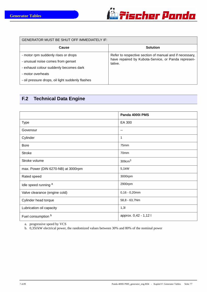
Generator Tables
7.4.09 Panda 4000i PMS_generator_eng.R04 - Kapitel F: Generator Tables Seite 77
GENERATOR MUST BE SHUT OFF IMMEDIATELY IF:
Cause Solution
- motor rpm suddenly rises or drops
- unusual noise comes from genset
- exhaust colour suddenly becomes dark
- motor overheats
- oil pressure drops, oil light suddenly flashes
Refer to respective section of manual and if necessary,have repaired by Kubota-Service, or Panda represen-tative.
F.2 Technical Data Engine
Panda 4000i PMS
Type EA 300
Govenour --
Cylinder 1
Bore 75mm
Stroke 70mm
Stroke volume 309cm3
max. Power (DIN 6270-NB) at 3000rpm 5,1kW
Rated speed 3000rpm
Idle speed running a 2900rpm
Valve clearance (engine cold) 0,16 - 0,20mm
Cylinder head torque 58,8 - 63,7Nm
Lubrication oil capacity 1,3l
Fuel consumption b approx. 0,42 - 1,12 l
a. progressive speed by VCSb. 0,35l/kW electrical power, the randomized values between 30% and 80% of the nominal power
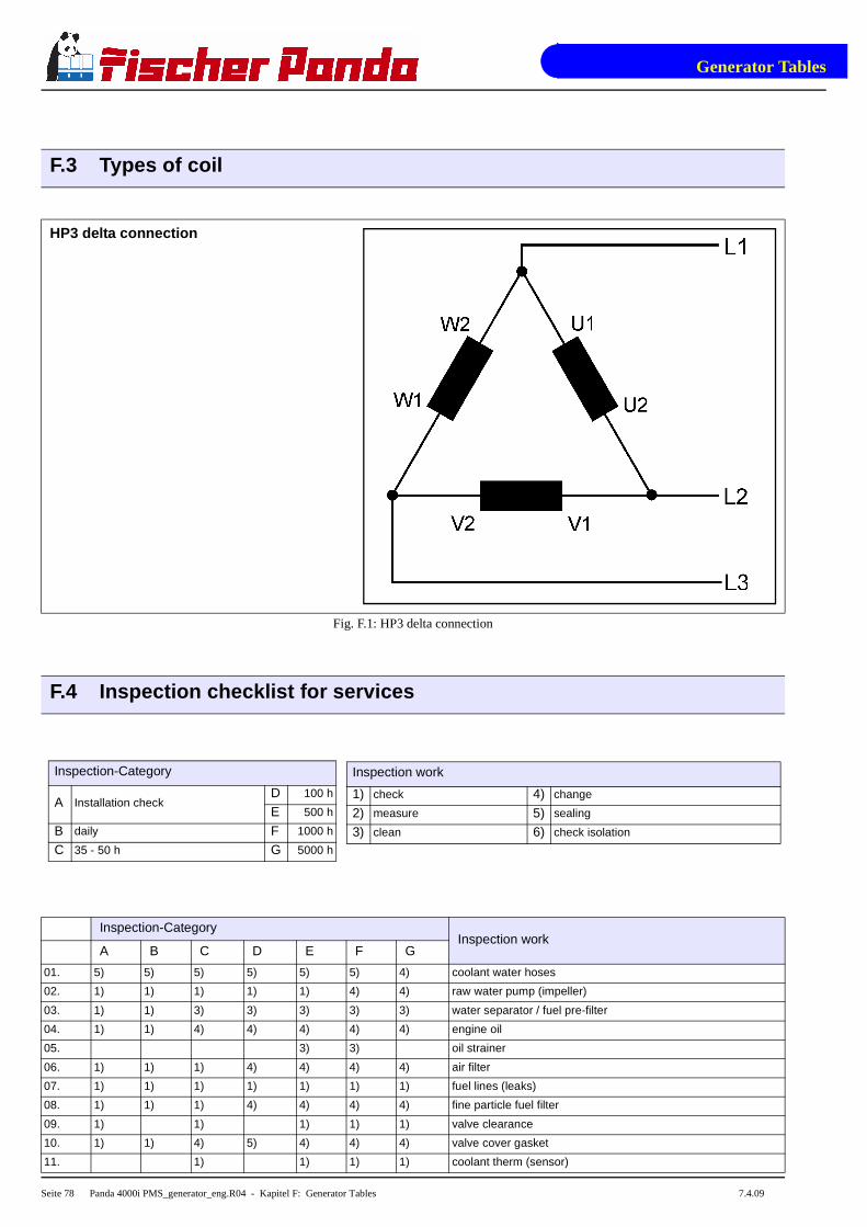
Generator Tables
Seite 78 Panda 4000i PMS_generator_eng.R04 - Kapitel F: Generator Tables 7.4.09
F.3 Types of coil
HP3 delta connection
Fig. F.1: HP3 delta connection
F.4 Inspection checklist for services
Inspection work
1) check 4) change
2) measure 5) sealing
3) clean 6) check isolation
Inspection-Category
A Installation checkD 100 h
E 500 h
B daily F 1000 h
C 35 - 50 h G 5000 h
Inspection-CategoryInspection work
A B C D E F G
01. 5) 5) 5) 5) 5) 5) 4) coolant water hoses
02. 1) 1) 1) 1) 1) 4) 4) raw water pump (impeller)
03. 1) 1) 3) 3) 3) 3) 3) water separator / fuel pre-filter
04. 1) 1) 4) 4) 4) 4) 4) engine oil
05. 3) 3) oil strainer
06. 1) 1) 1) 4) 4) 4) 4) air filter
07. 1) 1) 1) 1) 1) 1) 1) fuel lines (leaks)
08. 1) 1) 1) 4) 4) 4) 4) fine particle fuel filter
09. 1) 1) 1) 1) 1) valve clearance
10. 1) 1) 4) 5) 4) 4) 4) valve cover gasket
11. 1) 1) 1) 1) coolant therm (sensor)

Generator Tables
7.4.09 Panda 4000i PMS_generator_eng.R04 - Kapitel F: Generator Tables Seite 79
12. 1) 1) 1) 1) exhaust temp sensor
13. 1) 1) 1) 1) oil pressure sensor
14. 1) 1) 1) 1) 1) 1) belt tension
15. 1) 1) 1) 1) 4) 4) 4) "V" belts
16. 1) 1) Thermostat
17. 1) 1) 1) 1) 1) 1) 1) generator & engine screws
18. 1) 1) 1) 1) 1) 1) 1) unit's base mount screws
19. 6) 6) 6) 6) 6) 6) 6) check electrical cables
20. 1) 1) 1) 1) 1) 1) 1) motor reinforced mountings
21. 1) 1) 1) 1) 1) 1) 1) actuator mounting
22. 1) 1) 1) 1) 1) 1) 1) starter motor mounting screws
23. 1) 1) 1) 1) 1) 1) 1) screws generator-engine
24. 2) 2) 2) 2) 2) 2) input temp of coolant under load
25. 2) 2) 2) 2) 2) 2) outlet temp of coolant under load
26. 4) 4) generator rotor bearing
27. 1) 1) 1) 1) 1) signs of corrosion to generator
28. 1) 1) 1) 1) 1) 1) VCS function test
29. 2) 2) 2) 2) 2) 2) voltage without load
30. 2) 2) 2) 2) 2) 2) voltage under load
31. 2) 2) 2) 2) 2) 2) current under load
32. 2) 2) 2) 2) 2) 2) engine speed (rpm)
33. 1) 4) injector test
34. 1) 1) compression
35. 1) 1) 1) 1) 1) 1) 1) hose clips
36. 1) 1) 1) 1) 1) 1) 1) recifier
37. 1) 1) 1) 1) 1) 1) 1) test cable with temperature tester
F.5 Engine oil
Engine oil classification
Operating range:
The operating range of an engine oil is determined by SAE class. "SAE" is for the union of American engineers(Society of Automotives Engineers). The SAE class of an engine oil only informs over the viscosity of the oil (lar-ger number = more viscous, lower number = more highly liquidly) e.g. to 0W, 10W, 15W, 20, 30, 40. The first num-ber shows the liquid of cold weather, the second number refers to the fluidity with heat. Complete yearly oils haveusually SAE 10W-40, SAE 15W-40 etc.
Quality of oil:
The quality of an engine oil is specified by the API standard ("American Petroleum Institutes"). The API designa-tion is to be found on each engine oil bundle. The first letter is always a C.
API C for diesel engines
The second letter is for the quality of the oil. The more highly the letter in the alphabet, the better the C für Diesel-motoren.
Examples for diesel engine oil:
API CG Engine oil for highest demands, turbo-tested !

Generator Tables
Seite 80 Panda 4000i PMS_generator_eng.R04 - Kapitel F: Generator Tables 7.4.09
Engine oil types
above 25°C SAE30 or SAE10W-30
SAE10W-40
0°C to 25°C SAE20 or SAE10W-30
SAE10W-40
below 0°C SAE10W or SAE10W-30
SAE10W-40
F.6 Coolant specifications
Use a mixture of water and antifreeze. The antifreeze needs to be suitable for aluminium. The antifreeze concen-tration must be regularly checked in the interests of safety.
Fischer Panda recommend to use the product: GLYSANTIN PROTECT PLUS/G 48.
Engine coolant automotive industry Product descript ion
Product name GLYSANTIN ® PROTECT PLUS / G48
Chemical nature Monoethylenglycol with inhibitors
Physical form Liquid
Chemical and physical properties
Reserve alkalinity of 10ml ASTM D 1121 13 – 15 ml HCl 01 mol/l
Density, 20°C DIN 51 757 procedure 4 1,121 – 1,123 g/cm3
Water content DIN 51 777 part 1 max. 3,5 %
pH-value undiluted 7,1 – 7,3
Coolant mixture ratio
Water/antifreeze Temperature
70:30 -20°C
65:35 -25°C
60:40 -30°C
55:45 -35°C
50:50 -40°C
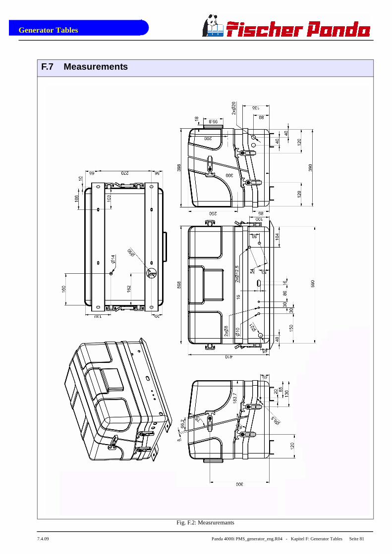
Generator Tables
7.4.09 Panda 4000i PMS_generator_eng.R04 - Kapitel F: Generator Tables Seite 81
F.7 Measurements
Fig. F.2: Measruremants

Generator Tables
Seite 82 Panda 4000i PMS_generator_eng.R04 - Kapitel F: Generator Tables 7.4.09
Blank

iCon
trol
_eng
.R03
7.4.
09
Panel Panda iControl
Fischer Panda GmbH
Panda i-series
Part 2: Panel Panda iControl Manual
74
Current revision status
Document
Actual: Panda_iControl_eng.R03_7.4.09
Replace: Panda_iControl_eng.R02
Revision Page
Update the whole manual
connection to 6000i update

Panda iControl
Panel_iControl_eng.fm Chapter A: Panda iControl - Page 75
Fischer Panda DatasheetA. Panda iControl
Art Nr. . 21.02.02.01H
Bez. Panda iControl
Document Hardware Software
Actual: R04
Replace: R03
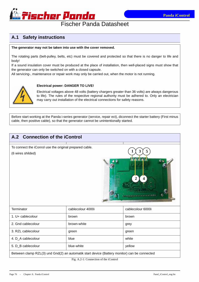
Panda iControl
Page 76 - Chapter A: Panda iControl Panel_iControl_eng.fm
Fischer Panda Datasheet
A.1 Safety instructions
The generator may not be taken into use with the co ver removed.
The rotating parts (belt-pulley, belts, etc) must be covered and protected so that there is no danger to life andbody!If a sound insulation cover must be produced at the place of installation, then well-placed signs must show thatthe generator can only be switched on with a closed capsule.All servicing-, maintenance or repair work may only be carried out, when the motor is not running.
Electrical power: DANGER TO LIVE!
Electrical voltages above 48 volts (battery chargers greater than 36 volts) are always dangerousto life). The rules of the respective regional authority must be adhered to. Only an electricianmay carry out installation of the electrical connections for safety reasons.
Before start working at the Panda i-series generator (service, repair ect), diconnect the starter battery (First minuscable, then positive cable), so that the generator cannot be unintentionally started.
A.2 Connection of the iControl
To connect the iConrol use the original prepared cable.
(6 wires shilded)
Terminator cablecolour 4000i cablecolour 6000i
1. U+ cablecolour brown brown
2. Gnd cablecolour brown-white grey
3. RZL cablecolour green green
4. D_A cablecolour blue white
5. D_B cablecolour blue-white yellow
Between clamp RZL(3) und Gnd(2) an automatik start device (Battery monitor) can be connected
Fig. A.2-1: Connection of the iControl
1 3 5
2 4

Panda iControl
Panel_iControl_eng.fm Chapter A: Panda iControl - Page 77
Fischer Panda Datasheet
Note
Regarding to the open electric board the iControl p anel has a protectrive class IP00.
Builded in a control board with a siutable seal (f. e. Sikaflex) IP66 can be reached.
A.3 Buttons and display of the iControl
Fig. A.3-1: Buttons and diplay of the iControl
Warning! At the Electronic board is an voltage of 4 50V. Only special trained persons areallowed to open the cover of the Electronic board. !!!DANGER TO LIVE!!!
2
4
1 3
2a
2b
2d2c
2e
2f
2g
1. Button „on/off“2. Display2a. Load indication in %2b. Oil pressure indication „OK“ oder „Fault“2c. Engine temp. indication2d. Exhaust elbow temp. indication
2e. Stator Winding temp. indication2f. Engine rpm indication2g. Operation hours3. Button „enter“4. Button „start/stop“

Panda iControl
Page 78 - Chapter A: Panda iControl Panel_iControl_eng.fm
Fischer Panda Datasheet
A.4 Engine control
The iControl Panel and Electronic Board is for driving the Panda i-series generator. Push the „on/off“ button tostart the panel(1). The panel will come up in the „stand by mode“.
„stand by mode“
in the stand by mode the iControl checks the generator
- Display shows welcome screen
- the Led-Light will switch off after 2 min. (energie save)
- push the „enter“ button“ to reset the LED-Light timer
- start the generator with the „start/stop“ button --> „run mode“
- start the generator with the „automatic start“ option --> „run mode“
„run mode“
Generator was started with the “start/stop“ button or with the „automatic start option“
- Display light is on
- Display shows generator data
- stop the generator with the „start/stop“ button --> „standby mode“
- stop the generator with the „automatic start“ option --> „standby mode“
A.5 Operation manual
A.5.1 Daily routine checks before starting
1. Oil Level Control (ideal level: 2/3 of maximum).
AtTTENTION! OIL PRESSURE CONTROL!
True, the diesel motor automatically switches off when there is a lack of oil, but it is very damaging for the motor, if the oil level drops to
the lowest limit. Air can be sucked in suddenly when the boat rocks in heavy seas, if the oil level is at a minimum. This affects the
grease in the bearings. It is therefore necessary to check the oil level daily before initially running the generator. The oil level must be
topped up to the 2/3 of maximum level, if the level drops min. mark.
2. State of Cooling Water.
The external compensation tank should be filled up to a 1/3 level of in a cold state. It is very important that large expansion area
remains above the cooling water level.
3. Open Sea Cock for Cooling Water Intake.(if necessary)
For safety reasons, the seacock should be closed after the generator is switched off for a longer time. It should be re-opened before
starting the generator.
4. Check Raw water Filter.
The raw water filter must be regularly checked and cleaned. The impeller fatigue increases, if residual affects the raw water intake.
Panda iControl
Panel_iControl_eng.fm Chapter A: Panda iControl - Page 79
Fischer Panda Datasheet5. Check all Hose Connections and Hose Clamps are Leakage.
Leaks at hose connections must be immediately repaired, especially the raw water impeller pump. It is certainly possible that the raw
water impeller pump will produce leaks, depending upon the situation. (This can be caused by sand particles in the raw water etc.) In
this case, immediately exchange the pump, because the dripping water will be sprayed by the belt pulley into the sound insulated cas-
ing and can quickly cause corrosion.
6. Check all electrical Lead Terminal Contacts are Firm.
This is especially the case with the temperature switch contacts, which automatically switch off the generator in case of faults. There is
only safety if these systems are regularly checked, and these systems will protect the generator, when there is a fault.
7. Check the Motor and Generator Mounting Screws are Tight.
The mounting screws must be checked regularly to ensure the generator is safe. A visual check of these screws must be made, when
the oil level is checked.
8. Switch the Land Electricity/Generator Switch to Zero before Starting or Switch Off all the Load.
For the automatic option make shure that the load is connected to the PMGi only, when the nominal output of
9. Check the Automatic Controls Functions and Oil Pressure.
Removing a cable end from the monitoring switch carries out this control test. The generator should then automatically switch off.
Please adhere to the inspection timetable (see Checklist in the appendix).
Attention! Make sure that the PMGi is connected wit h the generator. Never connect or dis-connect the PMGi when the generator is running. Thi s will destroy the PMGi. (it may burnor explode)
A.5.2 General
Very low Temperatures
The generator is disigned to start at temperatures up to -20 ° C. Please make sure, that the fuel is siutable foryour temperature range.
The electronic of the iControl changes the pre-glow time at the generator start according to the actual generatortemperature. The normal time at a cold engine is 8 sec. The pre-glow times rises at temperatures below 8 ° C anddrops (down to 0 sec.) at temperatures over 40°C.
Tips regarding Starter Battery
Fischer Panda recommends the use of a normal starter battery. If a genset is required for extreme winter conditi-ons, then the starter battery capacity should be doubled. It is recommended to charge the starter battery regularlyby a suitable battery-charging device (i.e., at least every 2 months). A correctly charged starter battery is neces-sary especially for low temperatures.

Panda iControl
Page 80 - Chapter A: Panda iControl Panel_iControl_eng.fm
Fischer Panda Datasheet Engine Oil at winter conditions.
Make sure using a siutable engine oil at winter conditions.
Do not use start help sprays or similar.
A.5.3 Long time run of the generator
Make sure the PMGi is not overloaded. The PMGi will switch off in this case.
We recommend to calculate the normal load should be at 80 % of the nominal load of the generator and PMGi.Normel load is in this case the load you need for a very long period. Nearly 100 % of the nominal power of thegenerator and PMGi can be used for 2-3 hours without any problems.
A.5.4 Start of the generator
1. Open the fuel valve (if necessary)
2. Close the battery switch (if necessary)
3. Push "on/off" button (turn iControl on).
Panel comes up with „Welcome“ screen
4. Push the „start/stop“ button to switch from „Welcome“ to the „Main“ screen
Screen switch to „Main“ screen
5. Push „start/stop“ button
The Engine pre-glow and start. It is not allowed to run the starter motor for more than 10 sec. If the generator does not start within this
time, the start is blocked for 20 sec.
Please check if the fuel is present at the generator, before you try to start the generator again. (and if the fuel is siutable for the tempe-
rature range)
6. Switch on the load when the nominal output of 230V / 50Hz is reached at the PMGi. See “Automatic start” onpage 81.
ATTENTION: If there is difficulty in starting - clo se the seacock ( Panda Marine Genera-tors only)
If the generator engine does not start immediately and further start attempts are necessary, thenthe seacock MUST be closed (i.e. for ventilating the fuel lines etc.) The cooling water impellerpump turns automatically and draws cooling water as long as the motor is turning. If the dieselmotor is running, the cooling water is blown out by the exhaust system gases. The cooling water
cannot be pressed through the exhaust as long as the diesel motor does not run at sufficient speed. This leads tosevere motor damage.
Open the seavalve as soon as the generator is start ed.
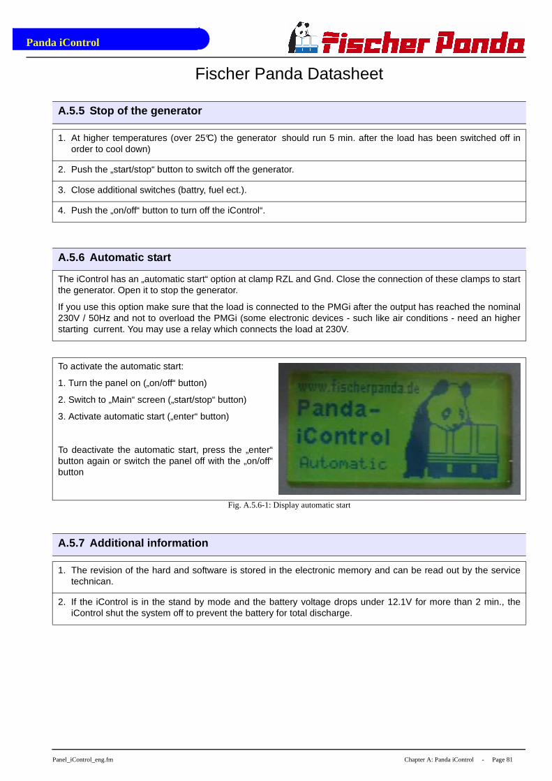
Panda iControl
Panel_iControl_eng.fm Chapter A: Panda iControl - Page 81
Fischer Panda Datasheet
A.5.5 Stop of the generator
1. At higher temperatures (over 25°C) the generator should run 5 min. after the load has been switched off inorder to cool down)
2. Push the „start/stop“ button to switch off the generator.
3. Close additional switches (battry, fuel ect.).
4. Push the „on/off“ button to turn off the iControl“.
A.5.6 Automatic start
The iControl has an „automatic start“ option at clamp RZL and Gnd. Close the connection of these clamps to startthe generator. Open it to stop the generator.
If you use this option make sure that the load is connected to the PMGi after the output has reached the nominal230V / 50Hz and not to overload the PMGi (some electronic devices - such like air conditions - need an higherstarting current. You may use a relay which connects the load at 230V.
To activate the automatic start:
1. Turn the panel on („on/off“ button)
2. Switch to „Main“ screen („start/stop“ button)
3. Activate automatic start („enter“ button)
To deactivate the automatic start, press the „enter“button again or switch the panel off with the „on/off“button
Fig. A.5.6-1: Display automatic start
A.5.7 Additional information
1. The revision of the hard and software is stored in the electronic memory and can be read out by the servicetechnican.
2. If the iControl is in the stand by mode and the battery voltage drops under 12.1V for more than 2 min., theiControl shut the system off to prevent the battery for total discharge.
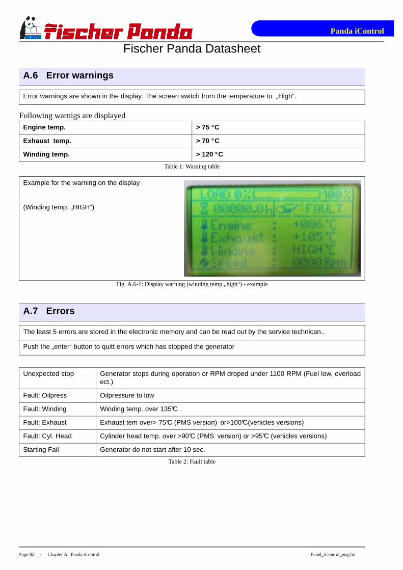
Panda iControl
Page 82 - Chapter A: Panda iControl Panel_iControl_eng.fm
Fischer Panda Datasheet
Following warnigs are displayed
A.6 Error warnings
Error warnings are shown in the display. The screen switch from the temperature to „High“.
Engine temp. > 75 °C
Exhaust temp. > 70 °C
Winding temp. > 120 °C
Table 1: Warning table
Example for the warning on the display
(Winding temp. „HIGH“)
Fig. A.6-1: Display warning (winding temp „high“) - example
A.7 Errors
The least 5 errors are stored in the electronic memory and can be read out by the service technican..
Push the „enter“ button to quitt errors which has stopped the generator
Unexpected stop Generator stops during operation or RPM droped under 1100 RPM (Fuel low, overloadect.)
Fault: Oilpress Oilpressure to low
Fault: Winding Winding temp. over 135°C
Fault: Exhaust Exhaust tem over> 75°C (PMS version) or>100°C(vehicles versions)
Fault: Cyl. Head Cylinder head temp. over >90°C (PMS version) or >95°C (vehicles versions)
Starting Fail Generator do not start after 10 sec.
Table 2: Fault table

Panda iControl
Panel_iControl_eng.fm Chapter A: Panda iControl - Page 83
Fischer Panda Datasheet
Example for an error display after the generator wasstopped.
(Oil Pressure failed)
Fig. A.7-1: Display warning (oil pressure failed) - example
A.8 Electronic board
The iControl panel has an electronic board which is mounted at the Generator. This board controls all generatorfunctions.
The bord is in a box and contains self healing fuses and relais.
For safety reasons it is not allowed to open the box of the electronic board.Inside there are up to450VAC. !!!DANGER TO LIFE.
Only special trained persons are allowed to change the board in case of anerror.
A.8.1 Location at the Panda i-series generator
Electronic board at the Panda 4000i PMS.
The location of the electronic board is depended onthe generator type and can vary.
Fig. A.8.1-1: Location of the electronic board
Panda iControl
Page 84 - Chapter A: Panda iControl Panel_iControl_eng.fm
Fischer Panda Datasheet
A.9 Technical data
A.9.1 Intended use
The Panda iControl is a part of the Panda i-series generator. It is not allowed to use the iControl at other genera-tors or applications.
The iControl must be connected with the electronic board at the generator.
Attention! See also the safety instructions in the generator and the PMGi manual. Therules of the respective regional authority must be adhered to. Only an electrician maycarry out installation of the electrical connection s for safety reasons.

Panda iControl
Panel_iControl_eng.fm Chapter A: Panda iControl - Page 85
A.9.2 Dimensions
Fig. A.9.2-1: Dimensions

Panda iControl
Page 86 - Chapter A: Panda iControl Panel_iControl_eng.fm
Intentionally Blank


![· the clean e s real performance & technology ad a ad craftsman spirit in beams in aas0lljte cpnfidence super silent [super silent] performance & quality](https://static.documents.pub/doc/80x56/5e9f9b512bc8e230aa6fefd0/the-clean-e-s-real-performance-technology-ad-a-ad-craftsman-spirit-in-beams.jpg)


