Computers & Structures, Vol. 25. No. 4 pp. 469-605, 1987 PANDA2 - PROGRAM FOR MINIMUM WEIGHT DESIGN OF STIFFENED, COMPOSITE, LOCALLY BUCKLED PANELS David Bushnell, Lockheed Palo Alto Research Laboratory, 3251 Hanover St, Palo Alto, CA 94304 (This is an abridged version. See the full-length paper for more: panda2.papers/1987.basic.pdf ) ABSTRACT PANDA2 finds minimum weight designs of laminated composite flat or curved cylindrical panels or cylindrical shells with stiffeners in one or two orthogonal directions. The panels or shells can be loaded by as many as five combinations of in-plane loads and normal pressure. The axial load can vary across the panel. Constraints on the design include crippling, local and general buckling, maximum tensile or compressive stress along the fibers and normal to the fibers in each lamina, and maximum in-plane shear stress in each lamina. Local and general buckling loads are calculated with the use of either closed-form expressions or discretized models of panel cross sections. An analysis branch exists in which local post buckling of the panel skin is accounted for. In this branch a constraint condition that prevents stiffener popoff is introduced into the optimization calculations. Much of this paper represents a tutorial run through the PANDA2 processors for a hat-stiffened panel under combined axial compression, in-plane shear and normal pressure. Examples follow in which results from PANDA2 are compared with those in the literature and those obtained with the STAGS and EAL computer programs. Results of an extensive study are given for an optimized, blade-stiffened panel design so that it buckles locally at about 10% of the design load. The axially stiffened panel is subjected to pure axial compression. pure normal pressure, combined axial compression and normal pressure, and combined axial compression and residual stresses and deformations that arise from a simulated curing process. An example is provided of a design process applied to a ring and stringer stiffened cylindrical shell similar in geometry and loading to the 2/3 interstage of the ARIANE 4 booster. 1. PURPOSE OF PANDA2 The purpose of PANDA2 is to find the minimum weight design of a stiffened flat or curved panel or complete cylindrical shell made of laminated composite material. Of course, simple isotropic panels and cylindrical shells can also be designed. 1.1 Definition of ‘panel' A panel is defined here as a structure that is either flat or is part of a cylinder. In most cases the user will probably want to analyze a flat panel or a panel that spans less than about 45° of circumference. However, in PANDA2 complete cylindrical shells can be treated by the user's setting up a model of a panel that spans 180°. The buckling loads given by PANDA2 for half of a cylindrical shell are the same as those given in the literature for a complete cylindrical shell because:
Transcript
Computers & Structures, Vol. 25. No. 4 pp. 469-605, 1987 PANDA2 - PROGRAM FOR MINIMUM WEIGHT DESIGN OF STIFFENED, COMPOSITE, LOCALLY BUCKLED PANELS David Bushnell, Lockheed Palo Alto Research Laboratory, 3251 Hanover St, Palo Alto, CA 94304 (This is an abridged version. See the full-length paper for more: panda2.papers/1987.basic.pdf ) ABSTRACT PANDA2 finds minimum weight designs of laminated composite flat or curved cylindrical panels or cylindrical shells with stiffeners in one or two orthogonal directions. The panels or shells can be loaded by as many as five combinations of in-plane loads and normal pressure. The axial load can vary across the panel. Constraints on the design include crippling, local and general buckling, maximum tensile or compressive stress along the fibers and normal to the fibers in each lamina, and maximum in-plane shear stress in each lamina. Local and general buckling loads are calculated with the use of either closed-form expressions or discretized models of panel cross sections. An analysis branch exists in which local post buckling of the panel skin is accounted for. In this branch a constraint condition that prevents stiffener popoff is introduced into the optimization calculations. Much of this paper represents a tutorial run through the PANDA2 processors for a hat-stiffened panel under combined axial compression, in-plane shear and normal pressure. Examples follow in which results from PANDA2 are compared with those in the literature and those obtained with the STAGS and EAL computer programs. Results of an extensive study are given for an optimized, blade-stiffened panel design so that it buckles locally at about 10% of the design load. The axially stiffened panel is subjected to pure axial compression. pure normal pressure, combined axial compression and normal pressure, and combined axial compression and residual stresses and deformations that arise from a simulated curing process. An example is provided of a design process applied to a ring and stringer stiffened cylindrical shell similar in geometry and loading to the 2/3 interstage of the ARIANE 4 booster. 1. PURPOSE OF PANDA2 The purpose of PANDA2 is to find the minimum weight design of a stiffened flat or curved panel or complete cylindrical shell made of laminated composite material. Of course, simple isotropic panels and cylindrical shells can also be designed. 1.1 Definition of ‘panel' A panel is defined here as a structure that is either flat or is part of a cylinder. In most cases the user will probably want to analyze a flat panel or a panel that spans less than about 45° of circumference. However, in PANDA2 complete cylindrical shells can be treated by the user's setting up a model of a panel that spans 180°. The buckling loads given by PANDA2 for half of a cylindrical shell are the same as those given in the literature for a complete cylindrical shell because:
1. the panel is assumed by PANDA2 to be simply supported along its straight edges; 2. a deep cylindrical panel spanning 180 degrees of circumference with simple supports along the generators at 0° and at 180 degrees behaves in the same way as a complete cylindrical shell: the number of circumferential half-waves in the 180° panel in the critical general instability buckling pattern is the same as the number of full circumferential waves in the 360-degree cylindrical shell.
Later an example is given in which a complete cylindrical shell with a single set of axial and shear loads that vary around the circumference is analyzed as a curved panel spanning 45 degrees and subjected to multiple sets of uniform loads. The panel is optimized for two combinations of in-plane loads: that corresponding to maximum axial compression and that corresponding to maximum in-plane shear. It is usually best to treat complete cylindrical shells in this way rather than try to set up a model for the entire cylinder, because buckling is usually local and concentrated in the areas of maximum load and because PANDA2 was really intended to treat panels, not complete cylindrical shells. Therefore, it is best applied to panels. In PANDA2 the curved edges of a cylindrical panel lie in the plane of the screen (axial coordinate x = 0) and parallel to the plane of the screen (axial coordinate x = L, where L is the length of the panel). The axial coordinate direction x is normal to the plane of the screen and pointing out of the screen. Thus, an axial load on the panel is normal to the screen, with axial tension pointing out of the screen. The width of the panel is the arc length along the curved edge. For example, the width of a deep cylindrical panel spanning 180 degrees is pi x R, where R is the radius of curvature. The coordinate in the width direction is called y. In the following, this direction is referred to with use of the words 'circumferential' or ‘hoop' or 'transverse'. The properties of the panel are assumed to be uniform in the axial (x) direction and periodic in the circumferential (y) direction. The panel may be unstiffened, stiffened by stringers alone, stiffened by rings alone, or stiffened by both rings and stringers. Stiffeners referred to as 'stringers' are always normal to the screen; stiffeners referred to as 'rings' always lie in the plane of the screen or parallel to the plane of the screen. Both stringers and rings must be uniformly spaced. All stringers must be the same. All rings must be the same. The rings can be different from the stringers. (NOTE: Since this was written sub-stiffeners can be included.) 1.2 Types of stiffeners PANDA2 can handle panels with stringers and/or rings with the following cross sections:
1. T-shaped 2. J-shaped (angle with flange away from skin) 3. Rectangular (blade stiffeners) 4. Hat-shaped or corrugated stiffeners. 5. Z-shaped riveted to panel skin (added after this paper was published) 6. Truss-core sandwich shell walls (added after this paper was published) 7. Sandwich wall construction (added after this paper was published) 8. Panels with major stringers and sub-stringers and major rings and sub-rings (added recently) 9. Panels with isogrid stiffening (added after this paper was published) 10. Panels the walls of which are of sandwich construction (added after this paper was published)
The portion of the panel skin near the stiffeners can have different properties than those of the panel skin away from the stiffeners. For example, optimum designs of panels with T-shaped stringers have thickened bases
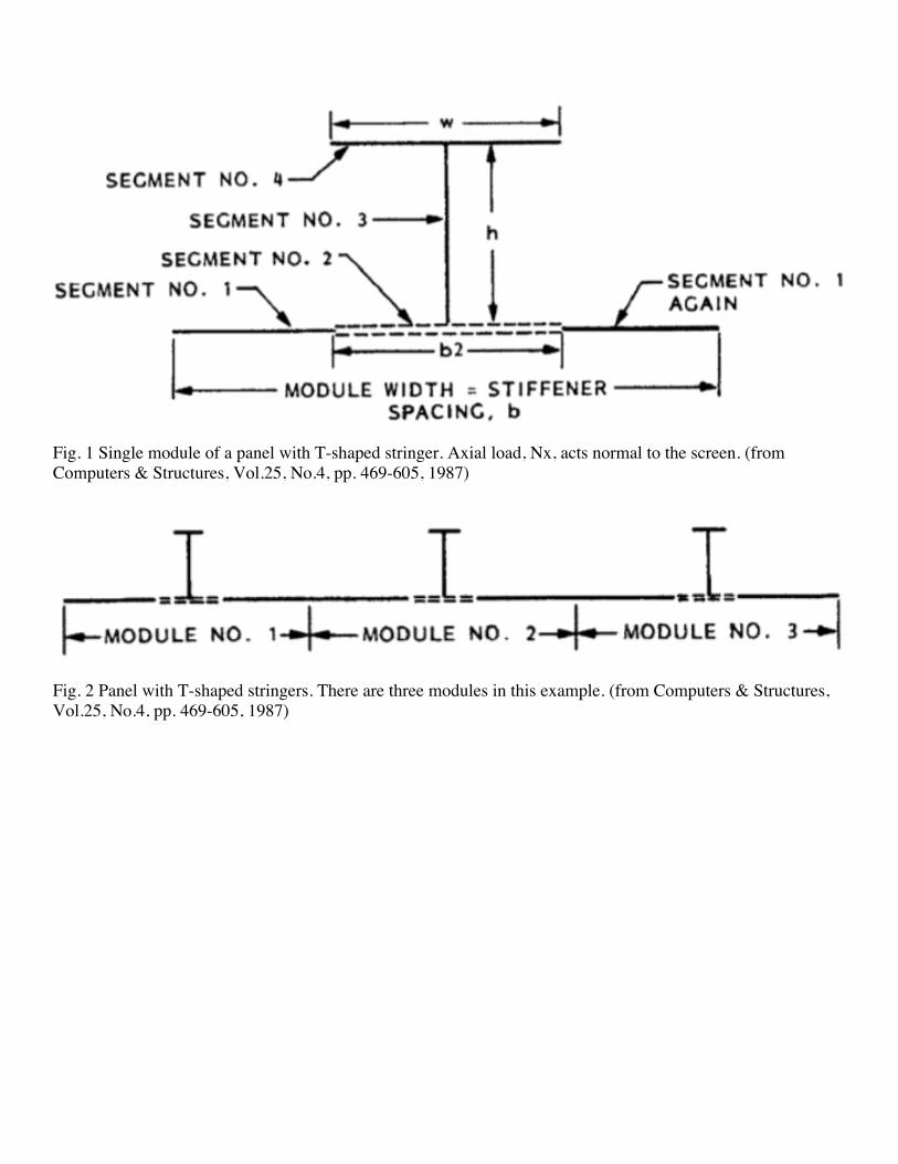
under the stringers that help to prevent fracture or delamination along the attachment line of the stringer to the skin. Figures 1 and 2 show an example of a flat panel with T-shaped stringers. 1.3 Boundary conditions In the PANDA2 system the panel is assumed to be simply supported along the two edges normal to the plane of the screen (at y = 0 and at y = panel width). The panel can be either simply supported or clamped along the other two boundaries (at x = 0 and x = L), but the conditions must be the same at both of these two boundaries. The PANDA2 analysis is always performed for simple support on all four edges. However, experience has shown that clamping at x = 0 and at x = L can be simulated by the analysis of a shorter simply supported panel: A panel clamped at x = 0 and x = L has general instability loads approximately equal to those of a panel simply supported at x = 0 and x = L/3.851/2. Therefore, in PANDA2. clamping at x = 0 and x = L is simulated by calculation of general instability or wide column instability of a simply supported panel with length equal to L/3.851/2. (NOTE: A more sophisticated panel length correction factor now exists, but the general idea remains.) In PANDA2 local buckling behavior and local stress concentrations near stiffeners are assumed to be independent of the boundary conditions along the four panel edges. This is a good assumption if there are more than two or three halfwaves in the local buckling pattern over the length and width of the entire panel. 1.4 Loading The panel can be loaded by up to five independent sets of in-plane loads, Nx, Ny, and Nxy and normal pressure p. Buckling loads, postbuckling behavior, and maximum stresses are calculated for each of the five loadsets applied by itself. Optimization is global, that is, PANDA2 determines the best design that is capable of surviving all of the five load sets when each set is applied separately, as it would be during different phases of a panel's lifetime or over different areas of a large, uniform structure such as a complete cylindrical shell. Associated with each of the five independent load sets, there can be two load subsets, Load Set A and Load Set B. Load Set A consists of what are termed in the PANDA2 output as 'eigenvalue loads'; these are loads that are to be multiplied by the critical buckling load factor (eigenvalue). Load Set B consists of loads that arc not multiplied by the critical buckling load factor. Stated mathematically, the critical load is given by Ncr = N(load set B) + (buckling load factor) x N(load set A). (1.1) 1.5 Types of analysis PANDA2 performs the following analyses: 1. Constitutive law
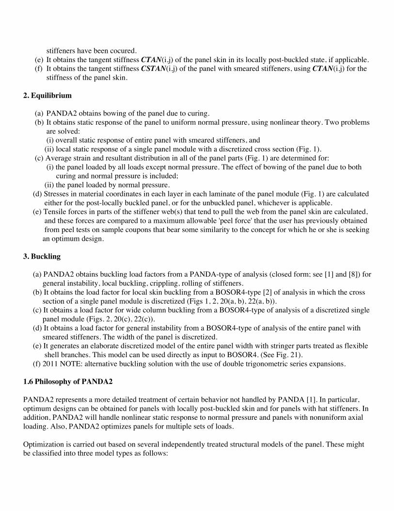
(a) PANDA2 obtains the integrated constitutive law (the 6 x 6 matrix C(i,j)) for each segment of a panel module (Figs I and 2).
(b) It obtains thermal resultants and strains from curing for each segment of a panel module. (c) It obtains the integrated constitutive law (the 6 x 6 matrix Cs(i j)) for the panel with either and both sets
of stiffeners 'smeared out'. ('Smearing out' the stiffeners means averaging their properties over the entire area of the panel. See eqns (40) of [8], for example.)
(d) It obtains the thermal forces and moments and residual deformations of a panel in which skin and
stiffeners have been cocured. (e) It obtains the tangent stiffness CTAN(i,j) of the panel skin in its locally post-buckled state, if applicable. (f) It obtains the tangent stiffness CSTAN(i,j) of the panel with smeared stiffeners, using CTAN(i,j) for the
stiffness of the panel skin. 2. Equilibrium
(a) PANDA2 obtains bowing of the panel due to curing. (b) It obtains static response of the panel to uniform normal pressure, using nonlinear theory. Two problems
are solved: (i) overall static response of entire panel with smeared stiffeners, and
(ii) local static response of a single panel module with a discretized cross section (Fig. 1). (c) Average strain and resultant distribution in all of the panel parts (Fig. 1) are determined for: (i) the panel loaded by all loads except normal pressure. The effect of bowing of the panel due to both curing and normal pressure is included; (ii) the panel loaded by normal pressure. (d) Stresses in material coordinates in each layer in each laminate of the panel module (Fig. 1) are calculated either for the post-locally buckled panel, or for the unbuckled panel, whichever is applicable. (e) Tensile forces in parts of the stiffener web(s) that tend to pull the web from the panel skin are calculated, and these forces are compared to a maximum allowable 'peel force' that the user has previously obtained from peel tests on sample coupons that bear some similarity to the concept for which he or she is seeking an optimum design. 3. Buckling (a) PANDA2 obtains buckling load factors from a PANDA-type of analysis (closed form; see [1] and [8]) for general instability, local buckling, crippling, rolling of stiffeners. (b) It obtains the load factor for local skin buckling from a BOSOR4-type [2] of analysis in which the cross section of a single panel module is discretized (Figs 1, 2, 20(a, b), 22(a, b)). (c) It obtains a load factor for wide column buckling from a BOSOR4-type of analysis of a discretized single panel module (Figs. 2, 20(c), 22(c)). (d) It obtains a load factor for general instability from a BOSOR4-type of analysis of the entire panel with smeared stiffeners. The width of the panel is discretized. (e) It generates an elaborate discretized model of the entire panel width with stringer parts treated as flexible shell branches. This model can be used directly as input to BOSOR4. (See Fig. 21). (f) 2011 NOTE: alternative buckling solution with the use of double trigonometric series expansions. 1.6 Philosophy of PANDA2 PANDA2 represents a more detailed treatment of certain behavior not handled by PANDA [1]. In particular, optimum designs can be obtained for panels with locally post-buckled skin and for panels with hat stiffeners. In addition, PANDA2 will handle nonlinear static response to normal pressure and panels with nonuniform axial loading. Also, PANDA2 optimizes panels for multiple sets of loads. Optimization is carried out based on several independently treated structural models of the panel. These might be classified into three model types as follows:
1.6.1 Model type 1. Included are PANDA-type models [1] for general, local and panel buckling, crippling of stiffener parts, and rolling of stiffeners with and without participation of the panel skin. Buckling load factors are calculated from closed-form equations rather than from discretized models. The formulas are given in [1]. (See [1, Table 1 and Figs 1-4].) (Numbers [i] refer to references given in the full paper.) 1.6.2 Model type 2. Buckling load factors and post-local buckling behavior are calculated for what is termed in PANDA2 a 'panel module'. Such a module is depicted in Figs 1 and 2. A module includes the cross section of a stiffener plus the panel skin of width equal to the spacing between stiffeners. In this model the panel module cross section is divided into segments, each of which is discretized and analyzed via the finite difference energy method [2]. Variation of deflection in the axial direction is assumed to be harmonic [sin(nx) or cos(nx)]. This one-dimensional discretization is similar to that used in the BOSOR programs for the analysis of shells of revolution [2]. In fact, many of the subroutines for buckling and vibration analysis are taken from BOSOR4 and modified slightly. The modification is necessary to handle prismatic structures instead of shells of revolution. Both local and wide-column instability can be handled with the same discretized structural model. Symmetry conditions are applied at the left and right edges of the single module model; that is, symmetry conditions are applied midway between stringers. The single module model gives a good approximation to the local skin buckling mode if there are more than three or four equally spaced stringers in the panel. What goes on locally between interior stringers in a panel, stringers that are rotating about their axes only, not bending, is only weakly affected by the boundary conditions at panel edges that may be several bays away. The wide column buckling model in PANDA2 is applied to an axial length of panel between adjacent rings, or if there are no rings, to the entire axial length of the panel, L. The wide-column buckling load predicted from the single panel module is always lower and usually reasonably close to the general instability load of the entire width of the panel between rings because the axial bending stiffness of a stringer-stiffened panel is usually much, much greater than the transverse bending stiffness of the portion of the panel between adjacent rings. Hence, the strain energy in the buckled panel, and therefore the buckling behavior, is only weakly dependent on bending of the panel transverse to the stringers. Therefore, the boundary conditions along the edges of the panel parallel to the stringers are not important. On the other hand, local bending of the skin and local deformation of the stringer parts in the wide column buckling mode may significantly affect the wide column buckling load. These effects are not included in the closed-form PANDA-type model of general instability, but they are included in the single panel module model of wide column buckling. Buckling modal interaction between local and general buckling that is due to initial local imperfections in the panel skin is included in PANDA2 [34]. 1.6.3 Model type 3. Also included in the PANDA2 collection of models is a discretized model of the entire width of the panel, treated in this case with stiffeners smeared out. This model is introduced only if the axial load varies across the width of the panel or if there exists normal pressure. 1.6.4 Overall philosophy of PANDA2. The overall philosophy of PANDA2 is to use several separate relatively simple models to capture different
phenomena, rather than use a single multi-dimensionally discretized finite element model with a large number of degrees of freedom. The aim is to produce a program that can yield optimum designs of rather sophisticated panels that experience very complex and very nonlinear behavior, and to do this without the use of large, general-purpose programs and their elaborate data base management systems. For example, PANDA-type models (Model type 1) are used in PANDA2 to obtain quick, preliminary designs that one can then use as starting designs in optimization analyses based on the more elaborate discretized panel module model. Also, PANDA-type models are used to obtain buckling load factors in cases for which the discretized panel module model is not applicable, to obtain knockdown factors for the effect of in-plane shear loading, to obtain preliminary estimates of how much growth in any initial panel bowing to expect under compressive in-plane loads, and to check if it is likely that a curved panel with uniform external pressure will collapse under the pressure acting by itself. Models of type 2 (single discretized module) and type 3 (discretization of entire width with smeared stiffeners) are used in tandem to obtain from nonlinear theory the complex behavior of a stiffened plate or shell loaded by normal pressure. Model type 3 is the only one that is valid if the axial load varies across the width of the panel. In the panels designed by PANDA2 the skin between stringers may buckle well before failure of the panel. The maximum stress components and therefore stress constraints in the optimization analysis are computed including local post buckling growth and modification of the local skin buckling mode as predicted by a modified form of a theory formulated by Koiter in 1946 [4]. Model type 2 (single discretized module) is the only model in PANDA2 valid for this analysis. After the optimum design is obtained, the user can, if no in-plane shear load is applied, check the accuracy of the general instability load predicted from the single-module model by running a multi-module model with BOSOR4 [2] (NOTE: now BIGBOSOR4, which handles many more shell segments than BOSOR4). The input data file for this multi-module model is generated automatically by the PANDA2 system. 1.7 Architecture of the PANDA2 system As with PANDA, the program PANDA2 consists of several independently executable processors which share a common data base. In the processor BEGIN the user supplies a starting design (perhaps a design produced by PANDA). In DECIDE he or she chooses decision variables for the optimization analysis and their upper and lower bounds, linking variables and their factors of proportionality, and 'escape' variables (explained in DECIDE). In MAINSETUP the user chooses up to five sets of combined in-plane loads and normal pressure; factors of safety for general instabililty, local instability and material failure; strategy parameters such as number and range of axial half-waves in the local buckling mode; and number of design iterations in the optimization problem. [2011 NOTE: PANDA2 now includes the effects of general, inter-ring, and local imperfections in the shapes of the general, inter-ring, and local buckling modes. In MAINSETUP the PANDA2 user now also supplies amplitudes for these buckling modal imperfection shapes. Furthermore, in MAINSETUP the PANDA2 user now also supplies a “conservativeness” index, ICONSV = -1 (least conservative approximations) or 0 (medium conservative approximations) or 1 (most conservative approximations, the preferred value). Still further, in MAINSETUP the PANDA2 user now chooses whether or not to employ an alternative buckling formulation (double trigonometric series solutions for local, inter-ring, and general buckling).]
The command PANDAOPT initiates a batch run of the PANDA2 mainprocessor, which consists of two main branches: in one branch the structural analyses (stress, buckling and post-buckling) are performed and in the other new designs are produced by the optimizer ADS, written by Vanderplaats [3]. 2011 NOTE ADDED HERE…..PANDA2 PAPERS: [1] Bushnell, D., et al (A) "PANDA2 - Program for minimum weight design of stiffened, composite, locally buckled panels", Computers and Structures, Vol. 25 (1987) pp. 469-605. See also: (B) "Theoretical basis of the PANDA computer program for preliminary design of stiffened panels under combined in-plane loads", Computers and Structures, v. 27, No. 4, pp 541-563, 1987; (C) "Optimization of composite, stiffened, imperfect panels under combined loads for service in the postbuckling regime", Computer Methods in Applied Mechanics and Engineering, Vol. 103, pp 43-114, 1993; (D) "Recent enhancements to PANDA2" 37th AIAA Structures, Dynamics, and Materials (SDM) Conference, April 1996; (E) "Approximate method for the optimum design of ring and stringer stiffened cylindrical panels and shells with local, inter-ring, and general buckling modal imperfections", Computers and Structures, Vol. 59, No. 3, 489-527, 1996, with W. D. Bushnell; (F) "Optimum design via PANDA2 of composite sandwich panels with honeycomb or foam cores", AIAA Paper 97-1142, AIAA 38th SDM Conference, April 1997; (G) "Additional buckling solutions in PANDA2", AIAA 40th SDM Conference, p 302-345, April 1999, with H. Jiang and N. F. Knight, Jr.; (H) "Minimum-weight design of a stiffened panel via PANDA2 and evaluation of the optimized panel via STAGS", Computers and Structures, Vol. 50, 569-602 (1994); (I) "Optimization of perfect and imperfect ring and stringer stiffened cylindrical shells with PANDA2 and evaluation of the optimum designs with STAGS", AIAA Paper 2002-1408, pp 1562-1613, Proceedings of the 43rd AIAA SDM Meeting, April, 2002, with C. Rankin; (J) “Optimum design of stiffened panels with substiffeners, AIAA Paper 2005-1932, AIAA 46th SDM Conference, April 2005, with C. Rankin; (K) “Difficulties in optimization of imperfect stiffened cylindrical shells, AIAA Paper 2006-1943, AIAA 47th SDM Conference, April 2006, with C. Rankin; (L).../panda2/doc/panda2.news, a continually updated file distributed with PANDA2 that contains a log of all significant modifications to PANDA2 from 1987 on; (M) “Optimization of Stiffened Panels in Which Mode Jumping is Accounted For,” AIAA Paper No. AIAA 97-1141, AIAA 38th SDM Conference, April 1997, with C. Rankin and E. Riks.; (N) “Global Optimum Design Of Externally Pressurized Isogrid Stiffened Cylindrical Shells With Added T-Rings,” International Journal of Non-Linear Mechanics Vol. 37, pp. 801–831, 2002; (O) “Optimization of an axially compressed ring and stringer stiffened cylindrical shell with a general buckling modal imperfection,” AIAA Paper No. AIAA 2007-2216, AIAA 48th SDM Conference, April, 2007; (P) "Optimization of panels with riveted Z-shaped stiffeners via PANDA2", in Advances in the Mechanics of Plates and Shells, Durban, D, Givoli, D., and Simmonds, J.G., Eds, Kluwer Academic Publishers, pp 79-102, 2001; (Q) “Global Optimum Design Of Externally Pressurized Isogrid Stiffened Cylindrical Shells With Added T-Rings,” International Journal of Non-Linear Mechanics Vol. 37, pp. 801–831, 2002.
Fig. 1 Single module of a panel with T-shaped stringer. Axial load, Nx, acts normal to the screen. (from Computers & Structures, Vol.25, No.4, pp. 469-605, 1987)
Fig. 2 Panel with T-shaped stringers. There are three modules in this example. (from Computers & Structures, Vol.25, No.4, pp. 469-605, 1987)
Fig. 20 Discretized model of a hat-stiffened module with local bifurcation buckling mode and wide column buckling mode (from Computers & Structures, Vol.25, No.4, pp. 469-605, 1987)
Fig. 22 (a) Discretized model of a tee-stiffened module with (b) a local bifurcation buckling mode (from Computers & Structures, Vol.25, No.4, pp. 469-605, 1987)
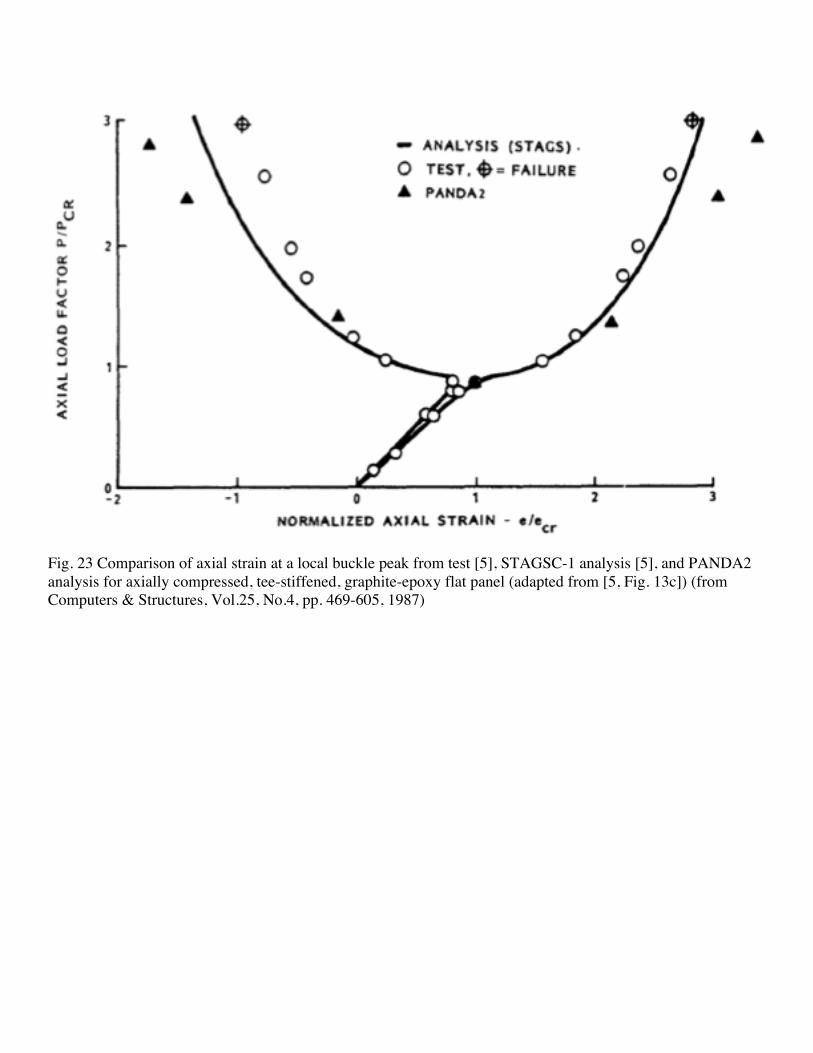
Fig. 23 Comparison of axial strain at a local buckle peak from test [5], STAGSC-1 analysis [5], and PANDA2 analysis for axially compressed, tee-stiffened, graphite-epoxy flat panel (adapted from [5, Fig. 13c]) (from Computers & Structures, Vol.25, No.4, pp. 469-605, 1987)
Fig. 48 Load-end-shortening for a uniformly axially compressed panel. The local buckling pattern has five axial half-waves. The STAGS result shows more axial stiffness because the STAGS model has stringers at each edge (four stringers in a width of 24 inches), whereas the panda2 model has three stringers (three modules) in the width of 24 inches. (from Computers & Structures, Vol.25, No.4, pp. 469-605, 1987)
Fig. 79 Applied overall moment M, axial compression P, and shear S; assumed resulting distributions of line loads Nx and Nxy in the shell; and replacement of the actual complete cylindrical shell with circumferentially varying line loads by a single cylindrical panel spanning 40 inches of circumference with three separate load sets, each of which acts alone and each of which has uniform line loads, Nx and Nxy. (from Computers & Structures, Vol.25, No.4, pp. 469-605, 1987)
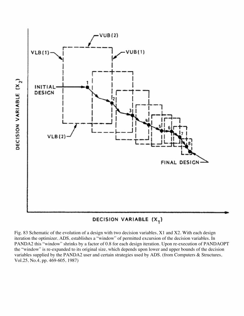
Fig. 83 Schematic of the evolution of a design with two decision variables, X1 and X2. With each design iteration the optimizer, ADS, establishes a “window” of permitted excursion of the decision variables. In PANDA2 this “window” shrinks by a factor of 0.8 for each design iteration. Upon re-execution of PANDAOPT the “window” is re-expanded to its original size, which depends upon lower and upper bounds of the decision variables supplied by the PANDA2 user and certain strategies used by ADS. (from Computers & Structures, Vol.25, No.4, pp. 469-605, 1987)