B02-I167E Installation Manual Panoramic and Cephalo Radiograph BelmaX CM Notice ★Read this installation Manual thoroughly before Installation. The classification is shown as follows According to the type of protection against electric shock. : Class Ⅰ According to the degree of protection against electric shock. : Type B applied part TAKARA BELMONT U.S.A., INC.
Transcript
B02-I167E
Installation Manual
Panoramic and Cephalo Radiograph
BelmaX CM
Notice ★Read this installation Manual thoroughly before Installation.
The classification is shown as follows According to the type of protection against electric shock. : Class Ⅰ
According to the degree of protection against electric shock. : Type B applied part
TAKARA BELMONT U.S.A., INC.
B02-I167E
Caution! This manual provides information and instruction for the installation, assembly, and certification procedures for the “BELMAX-CM” X-Ray. The instructions contained in this book should be thoroughly read and understood before attempting to install the “BELMAX-CM” unit. After the installation is completed, file this manual and refer back to it when performing periodic maintenance.
B02-I167E
CONTENTS
01. Introduction 01 – 1/1 02. Warning 02 – 1/2 03. Pre-Installation Instructions 03 – 1/2 04. Specifications 04 – 1/2 05. Names of each parts and Dimensions 05 – 1/2 06. List of Parts and Accessories 06 – 1/2 07. Installation Instructions 07 – 1/19 08.Post-Installation instructions 08 – 1/4 09. Technical Data 09 – 1/9 10. Methods to install LAN Board for Panoramic Radiography 10 – 1/3 11. Methods to install a TWAIN driver in imaging software 14- 1/3 12. Contact information 16- 1/1
B02-I167E 01 01. Introduction 1. Observe “Warning” and “Prohibition” matters in this Installation Manual. 2. Read this Installation Manual thoroughly to prevent an accident or trouble. 3. If you have any unclear matters in installation, reconfirm it by reading this Installation Manual. 4. After installation, read Operation Manual to understand operation procedures. 5. Discharge Be sure to observe Installation Manual. If accidents or troubles of the equipment happen due to improper
installation, we can not be responsible for those accidents or troubles. 6. Repair and repair parts supply Repair and repair parts supply is available for 10 years from discontinued date. 7. mark means “ Attention, consult accompanying documents “.
B02-I167E 02
02.WARNING
WARNING Always conform to the safety work standards to assure safety for workers and other people concerned. Repair work for internal parts of the equipment involves high risk. This should be strictly conducted by an authorized service personnel only.
Meanings
DANGER Explains danger that may cause serious adverse effect to a human body.
WARNING Explains an instruction where personal injury or physical damage may occur
CAUTION Explains an instruction that should be observed for safety reasons
NOTE
States descriptions which serve to improve work efficiency and to help user to understand instructions in themanual
B02-I167E 02
DANGERThis equipment is electrical equipment. Do not splash water Such action causes an electric shock or a trouble of the equipment
WARNING This X-ray Unit may be dangerous to patient and operator unless safe exposure factors and operating instructions are observed.
WARNINGThis equipment should be installed in an X-ray room surrounded by walls that have over 1.0 mmPb leadequivalence. Exposure switch should be installed outside of the X-ray room.
WARNING The floor should be able to support 600 lbs. dead load and should be rigid.
WARNING Do not put things in the area where equipment moves.
WARNINGThose who install X-ray apparatus should wear X-ray protector apron.
WARNINGOperator should pay attention to patient when moving Sliding Unit up and down
WARNING LASER RADIATION, DO NOT STARE INTO A BEAM, CLASS 2 LASER PRODUCT 1.Laser Beam is applied. For safety, instruct patient not to look at the laser beam. 2.Before the beam is lightened, lower Frankfort Line Beam to bottom. 3.Do not set the beam to patient's eyes.
CAUTION Do not turn ROTATION ARM by hand. It might cause a trouble of the equipment.
B02-I167E 03
03. Pre-Installation Instructions [1] Required tools / materials for the installation 1. Manuals
1. Installation Manual for BELMAX-CM. 2. Operation Manual for BELMAX-CM
2. Measurement Instruments and Tools 2. 1. Measurement Instruments
1) Digital Multi Meter with an accuracy of 1%, capable of measuring 150VAC and 20mA DC, and capable of indicating true RMS value within one second
2) Fluorescent Screen 2. 2. Tools
1) Philips Head Screwdrivers (Small and Big) 2) Slotted Head Screwdrivers (Small, Anti-Static type) 3) Nut Drivers (M6, M5, M4 and M3) 4) Ratchet wrench 5) Allen keys 6) Cutting Nippers 7) Long nose nippers 8) Hammer 9) Electric Drill 10) Drill bit 8.3mm = 21/64”(which can drill in wall and a floor )
2. 3. Others
1) Ethanol for disinfections 2) Waste 3) Cleanser
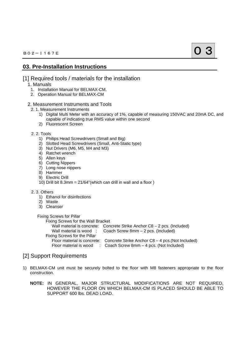
Fixing Screws for Pillar Fixing Screws for the Wall Bracket Wall material is concrete: Concrete Strike Anchor C8 – 2 pcs. (Included) Wall material is wood : Coach Screw 8mm – 2 pcs. (Included) Fixing Screws for the Pillar Floor material is concrete: Concrete Strike Anchor C8 – 4 pcs.(Not Included) Floor material is wood : Coach Screw 8mm – 4 pcs. (Not Included) [2] Support Requirements 1) BELMAX-CM unit must be securely bolted to the floor with M8 fasteners appropriate to the floor
construction. NOTE: IN GENERAL, MAJOR STRUCTURAL MODIFICATIONS ARE NOT REQUIRED,
HOWEVER THE FLOOR ON WHICH BELMAX-CM IS PLACED SHOULD BE ABLE TO SUPPORT 600 lbs. DEAD LOAD.
2) The wall bracket must be attached to the wall studs with minimum of two 5/16 x 3 inch lag screws If
Studs are not available at the appropriate installation point. Or if stud wall construction is not used, a rigid structure capable of supporting 100 lbs. pull out must be provided.
NOTE: DO NOT USE THIS UNIT WITHOUT CORRECT BRACING
3) Screw slots are oversized to allow for positioning/leveling. Appropriate washers must be used on all fasteners.
B02-I167E 03
[3] Electrical Requirements 1) Power Supply BELMAX-CM X-Ray operates on a power supply of 120 VAC. A three wire GROUNDED circuit,
separately connected to the central distribution panel with an over current protection device rated for 20 amperes. Recommended wire size is 12 AWG. But if the wire run distance is to exceed 50 feet, 10 AWG is required. For wire run distance in excess of 75 feet, up to 125 feet, 8 AWG is required.
2) All connections, workmanship and materials used must comply with the national Electric Code and local
codes.
B02-I167E 04
04. Specifications
Model Digital Panoramic and Cephalometric Radiograph BelmaX CM Input Power 120V (+/- 10%) 60Hz 1φ Power 2.0kW High Tension Generator High Tension Generator (100kHz)
Exposure Method Manual Tube Voltage 60kV~100kV (1kV step) Tube Current 2.4.6.8.10.12mA (2mA step) X-ray Tube D-052SB(Toshiba) Focal Spot 0.5×0.5mm Total Filtration 2.5mmAl(Min) CCD sensor Both as Panorama and Cephalo
Exposure Mode
Panoramic
Child Adult Orthoradial
Lateral Cephalo
Maxillary Sinus
Frontal
TMJ
Lateral Frontal
Exposure Time
Panorama :7sec/12sec Cephalo Lateral:2.9sec(short time mode) 4sec(normal time mode) Frontal:3.2~5sec
Positioning tools Panorama・Maxillary Sinus: Chin Rest+ Head Holding Rod TMJ Lateral・Frontal:Ear Rod
―
Weight 417 lb(189 kg)
B02-I167E 04 Environmental condition for Operation Temperature : 41~95F (5~35℃) Humidity : 30~85% Pressure : 700~1060 hpa Environmental condition for Storage Temperature : 14~140F (-10~60℃) Humidity : 10~95% Pressure : 700~1060 hpa Environmental condition for Transportation Temperature : 14~140F (-10~60℃) Humidity : 10~95% Pressure : 700~1060 hpa
B02-I167E 05 05. Name of Each Parts and Dimension
Name of Each Part BelmaX CM
Cep
halo
arm
Cep
halo
Sta
t
Cep
halo
sen
sor
Arm
ASS
Y
X-ra
y ge
nera
tor
Pilla
r
Res
t ASS
Y
X-ra
y sw
itch
Pano
ram
a se
nsor
Grip
Beam
ope
ratio
nal p
anel
Slid
ing
unit
Rot
atio
n un
it
B02-I167E 05 2.Dimensions
BelmaX CM
B02-I167E 06 06. List of Parts and Accessories
1. Parts of Equipment
1) Pillar 2) Rotation Unit
3) Chinrest Unit
4) Upper Cover of Pillar
5) Rotation Unit Cover
6) Sliding Unit Cover
7) Cephalo Arm
8) Base
2. Accessories for Installation 1) Shaft(φ10 L=400)
2) Cable Band (5 pcs.) 3) Mounting Upper Cover of Pillar 4) Countersunk Screw (M3×6 2pcs.) 5) Mounting Back Cover of Sliding Unit
Countersunk Screw (M6×8 4pcs.) (BelmaX CM) 6)Mounting Cephalo Arm
Socket Head Screw (M6×16 4Pcs.) (BelmaX CM) 7)Positioning of Cephalo Arm
taper pin (Φ5×25 2pcs.) (BelmaX CM) 8)Fixing Bolt for Sliding Unit and Rotation Unit. Hexagon Bolt (Φ8×35 4pcs.), Washer (Φ8 4pcs.), Spring Washer (Φ8 4pcs.), and
Taper Pin (φ5×25 2pcs.) 9)Fixing Bolt for Sliding Unit and Rest Unit. Socket Head Screw (M6×20 6pcs.) 10)Mounting Screw for Rotation Unit Cover Bind Screw M3 ×8 (2pcs.) Nylon Washer (Φ3 2pcs.)
11)Mounting Screw for Sliding Unit Cover Socket Head Screw(M3×10 6pcs.) Bind Screw (M3×8 2pcs.) Setscrew (M3×8 2pcs.) Nylon Washer (Φ3 6pcs.) 12)Mounting Screw for Base and Block (with Base) 13)Mounting Screw for Pillar and Block (with Base)
14)Fixing Bolt for Base (with Base) 15)Fixing Bolt for Pillar (Floor Fixation) 16) Fixing Bolt for Wall Bracket
B02-I167E 06 3. Accessories 2. 1. Accessories
1. Head Holding Rods for Panorama and MS 6. Bite Block for Panorama
2. Ear Rods for T.M.J. LA 7. Bite Block Cover (Disposable)
3. Ear Rods for T.M.J. PA 8. Exposure Switch Holder
4. Chinrest for Panorama
5. Chinrest for MS
B02-I167E 07
07. Installation Instructions
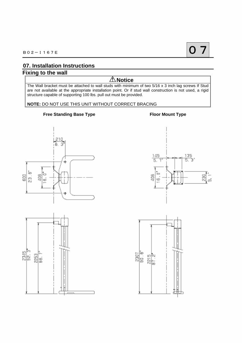
Fixing to the wall Notice
The Wall bracket must be attached to wall studs with minimum of two 5/16 x 3 inch lag screws If Stud are not available at the appropriate installation point. Or if stud wall construction is not used, a rigid structure capable of supporting 100 lbs. pull out must be provided.
NOTE: DO NOT USE THIS UNIT WITHOUT CORRECT BRACING
Free Standing Base Type Floor Mount Type
B02-I167E 07
When concrete strike anchors (C8-50) are used ①Drill two holes of 1-1/5” (30mm) depth with a drill bit of 21/64” (8.3mm) diameter on the wall where the
wall mounting bracket is fixed.
②Attach M8 nuts on concrete strike anchors. Turn nut and leave 5 to 6 screw threads above a nut.
③Insert a concrete strike anchor into a hole.
④Strike the pin until the pin is flush with top of the anchor.
⑤Remove the M8 nut.
B02-I167E 07
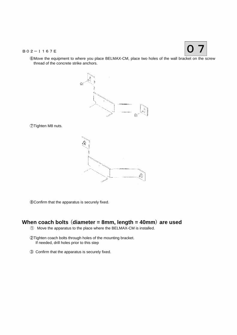
⑥Move the equipment to where you place BELMAX-CM, place two holes of the wall bracket on the screw thread of the concrete strike anchors.
⑦Tighten M8 nuts.
⑧Confirm that the apparatus is securely fixed. When coach bolts (diameter = 8mm, length = 40mm) are used
① Move the apparatus to the place where the BELMAX-CM is installed.
②Tighten coach bolts through holes of the mounting bracket. If needed, drill holes prior to this step
③ Confirm that the apparatus is securely fixed.
B02-I167E 07
How to fix on the floor Warning
BELMAX-CM unit must be securely bolted to the floor with M8 fasteners appropriate to the floor construction (lag screw, concrete strike anchor, etc) NOTE: IN GENERAL, MAJOR STRUCTURAL MODIFICATIONS ARE NOT REQUIRED,
HOWEVER THE FLOOR ON WHICH BELMAX-CM IS PLACED SHOULD BE ABLE TO SUPPORT 600 lbs. DEAD LOAD.
When concrete strike anchors (C8-80) are used
① Move the apparatus to the place where it will be installed.
② Drill four holes of 2” (50mm) depth through the holes of pillar stand by using 21/64” (8.3mm)drill bit.
③ Insert a concrete strike anchor into each hole.
④ Attach a M8 nut on a concrete strike anchor. Turn a nut and leave 8 to 10 screw threads above the nut.
B02-I167E 07
⑤ Strike the pin until pin is flush with top of the anchor. ⑥ Fix concrete strike anchor by tightening a M8 nut. ⑦ Be sure that the apparatus is securely fixed.
B02-I167E 07
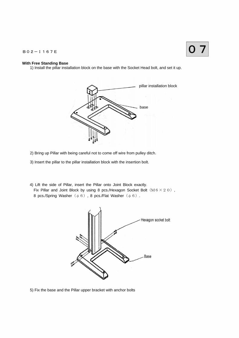
With Free Standing Base
1) Install the pillar installation block on the base with the Socket Head bolt, and set it up.
2) Bring up Pillar with being careful not to come off wire from pulley ditch.
3) Insert the pillar to the pillar installation block with the insertion bolt. 4) Lift the side of Pillar, insert the Pillar onto Joint Block exactly. Fix Pillar and Joint Block by using 8 pcs./Hexagon Socket Bolt(M6×20), 8 pcs./Spring Washer(φ6), 8 pcs./Flat Washer(φ6). 5) Fix the base and the Pillar upper bracket with anchor bolts
pillar installation block
base
B02-I167E 07 Method of installing the earth wire
① Run the supplied earth wire from the hole located at the bottom of the column to a grounding terminal. Secure the conductor with a screw. Refer to the figure below.
Screw
Earth Wire
Column
B02-I167E 07 1. Installation Procedure 1. Lay the column faces down as shown, supporting it with approximately 6” of lumbers covered by the cloth, at the both ends.
2. Remove the screw (M6 X 65) which fixes the counter weight frame to the main body.
3. Move the Sliding Unit until the hole of Sliding Unit and the one of counter weight frame align.
Flat head cap screw
B02-I167E 07
4. Insert the steel rod (provided) into the hole on the Pillar.
5. Attach the Wall Bracket to the upper part of Pillar by two flat head cap screws.
6. Attach the Electromagnetic Brake Control Cable at the upper part of Bracket by a cable tie. Connect this
cable to CNK Board located on front side of the Sliding Unit. 7. Erect the Pillar and mount on the floor.
8. Attach the Pillar base and Wall Bracket.
Bracket Flat Head Screw
Steel Rod
Fix with the Cable tie
Flat Head Screw Wall Bracket Flat Head Cap screw
B02-I167E 07
9. Put Counter Weights into Counter Weight Frame from back side of the Pillar.
10. Attach the Counter Weight Cover on the Counter Weight Frame.
11. Attach the Pillar Cover on the back side of Pillar.
Counter Weights
Flat Head Screw
Counter Weight Cover
Back Cover of Pillar
Screw + Nylon Washer
B02-I167E 07
12. Remove screws to release brake located at upper part of the Pillar. Caution: Sliding Unit might move. Be careful not to pinch fingers.
13 Attach the Cephalo Arm on the back side of Sliding Unit. Align the Cephalo arm by using taper pins. Then
fix it by Socket flat head cap screws.
After mounting Cephalo Assy to the Cephalo Arm with countersunk head screw, tighten fixing screw.
Taper Pin
Socket flat head cap screw
countersunk head screw
Cephalo Arm
fixing screw. Cephalo Assy
Washer
Screws for Brake Release
B02-I167E 07
14. Wiring of Rotation Unit, Sliding Unit, and Cephalo.
1) Connect harness CNL2(3) from Rotation Unit with harness CNL2(3P) from the Sliding Unit 2) Connect harness CN1(34P) from the Rotation Unit with connector CN1(34P) of CNK BOARD in the
Sliding Unit. Lock broken line securely
3) Connect harness CN2(3P) from the Rotation Unit with connector CN2(3P) of CNK BOARD in the Sliding Unit
4) Connect the LAN cable from PC with the switching hub.
5) Connect the connector of the Sliding Unit with connector from the X-ray SW
6) For Cephalo ①Connect each harness and the cable from the Cephalo arm with CNK BOARD and the hub in the
Sliding Unit.
Cephalo Arm The No. of Pin Sliding Unit CND1 5p CNK BOARD (CND1)
②After connecting, check if each harness and cables don’t have any damage. ③Detach the cover of the Cephalo pillar, and remove the cable suppression, and connect the harness
from Cephalo arm with each boards of the Cephalo pillar.
Cephalo arm
Cephalo arm with each boards
cable suppression
B02-I167E 07
Cephalo arm The No. of Pin Cephalo driving part CN3 10P Motor driver
15. By holding the carriage holders with two men, hook the rotation unit ass’y onto the sliding unit. Align rotation unit by using taper pins. Then fix it by hexagon bolts.
16. Remove Carriage Holders from the Rotation Unit
17. Connect the wire harness from the Rotation Unit to the CNK Board and the CNL2 Board located on front
side of the Sliding Unit. 18. Remove the shaft that has been inserted into the pillar. 19. Put the Sliding Unit Cover on the Sliding Unit.
Sliding Unit Cover
Put it from underneath
Hexagon Bolt
Taper Pin
Carriage Holder for Rotation Unit
20. Insert the Chinrest Ass’y to lower part of the Sliding Unit while pulling the sliding unit cover. Attach the chinrest ass’y by four cap screws.
21. Connect wire harness from the Sliding Unit to the connector in Chinrest Ass’y.
Sliding Unit The No. of Pin Rest Unit CNR1 6p CNR1 CNR2 6p CNR2 CNM 4p CNM
22. Attach the lower cover to the bottom of the Chinrest Ass’y.
Pull Sliding Unit Cover
Cap Screws Chinrest Ass’y
Lower Cover
Flat Head Screw
B02-I167E 07
23. Attach the Sliding Unit Cover to the Frame.
24. Remove the steel rod which was inserted to the Frame of the Sliding Unit. 25. Attach the Rotation Unit Cover by two screws from the top and by a screw from the bottom. Put the lid to the
bottom hole.
Screw Socket Head Screw
Screw
Bind Screw + Nylon Washer
Lid
B02-I167E 07
26. Attach the Upper Cover on the Pillar by using two flat head screws. 27. Insert the Chinrest and Head Holding Rods to the Chinrest Unit.
Flat Head Screw
Upper Cover for Pillar
Bite Block
Chinrest
B02-I167E 08
08. Post-Installation Instructions
1. Check listed items by referring to the Operation Manual 2. Confirm the operation without X-ray Keep depressing 【FACTOR DOWN】Key until Tube Voltage becomes 0kV. Then test operation. 3. Confirm the operation with X-ray 3. 1. Cover radiation aperture with lead. 3. 2. Set exposure condition by referring the Operation Manual. 1) Exposure Orbit → Panorama
B02-I167E 08 4. Complete the following Check List 1. Power
1) Measurement of Input Power Voltage Vac 2) Does 1) meet the rating description on the Controller plate? □ OK □ NG 3) Rating Values of the Circuit Protector on the Sliding
Unit Voltage V Current A
4) Are there any problems when the power plug is
inserted? Heat □ OK □ NGAllophone □ OK □ NGOff-flavor □ OK □ NG
5) Does the Power Code have a scratch or a crack? □ OK □ NG
2. Operation 1) After Power On, does the main body have a problem? Heat □ OK □ NG
Allophone □ OK □ NG Off-flavor □ OK □ NG
2) After depressing the "RESET" key, is “READY” displayed? □ OK □ NG 3) Does the main body move with up / down switch? □ OK □ NG 4) Does up / down operation of main body have a
problem? Allophone □ OK □ NG
5) Does up / down operation accelerate after keep depressing up /
down switch for more than 3 sec.? □ OK □ NG
6) Does Sliding Unit stop at the highest and the lowest position?
□ OK □ NG
7) Positioning Beams in Panorama and MS mode.
7-1) Are all positioning beams turned on by depressing up / down switch of Frankfort Beam or by depressing forward / backward switch of Focus Beam?
□ OK □ NG
7-2) Does Up / down operation of Frankfort Beam work by
depressing up / down switch. □ OK □ NG
7-3) Does Frankfort Beam stop at the max position after keep
depressing up / down switch? □ OK □ NG
7-4) Dose Forward / backward operation of Focus Beam work by
depressing forward / backward switch? □ OK □ NG
7-5) When Focus Beam moves to the maximum positions, are the
values on display +25 and –25? □ OK □ NG
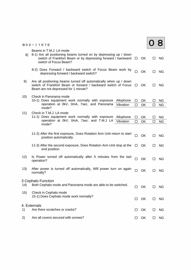
B02-I167E 08 8)
Beams in T.M.J. LA mode 8-1) Are all positioning beams turned on by depressing up / down
switch of Frankfort Beam or by depressing forward / backward switch of Focus Beam?
□ OK □ NG
8-2) Does Forward / backward switch of Focus Beam work by
depressing forward / backward switch? □ OK □ NG
9) Are all positioning beams turned off automatically when up / down
switch of Frankfort Beam or forward / backward switch of Focus Beam are not depressed for 1 minute?
□ OK □ NG
10) Check in Panorama mode
10-1) Does equipment work normally with exposure operation at 0kV, 0mA, 7sec. and Panoramamode?
Allophone □ OK □ NG Vibration □ OK □ NG
11) Check in T.M.J. LA mode 11-1) Does equipment work normally with exposure
operation at 0kV, 0mA, 7sec. and T.M.J LA mode?
Allophone □ OK □ NG Vibration □ OK □ NG
11-2) After the first exposure, Does Rotation Arm Unit return to start
position automatically. □ OK □ NG
11-3) After the second exposure, Does Rotation Arm Unit stop at the
end position. □ OK □ NG
12) Is Power turned off automatically after 5 minutes from the last
operation? □ OK □ NG
13) After power is turned off automatically, Will power turn on again
normally? □ OK □ NG
3 Cephalo Function 14) Both Cephalo mode and Panorama mode are able to be switched.
□ OK □ NG 15) Check in Cephalo mode
15-1) Does Cephalo mode work normally?
□ OK □ NG
4. Externals 1) Are there scratches or cracks? □ OK □ NG 2) Are all covers secured with screws? □ OK □ NG
B02-I167E 09
9.Technical data 1.Wall Bracket. The distance between the column and the wall is 5-3/4” (145mm). 2.Compliance with International Standards BELMAX-CM complies with the following standards IEC 60601-2-7 (1998) IEC 60601-2-28(1993-03) IEC 60601-2-32(1994-03) 3.Classification 1.According to the type of protection against electric shock
a) Equipment energized from external electrical power source. Class I equipment 2.According to the degree of protection against electric shock
Type B applied part 3.Protection against Ingress of water Ordinary 4.Equipment is not suitable for use in the presence of a FLAMMABLE ANAESTHETIC MIXTURE WITH AIR OR WITH OXYGEN OR NITROUS OXIDE 5.According to the mode of operation: Continuous Operation with Short-Time Loading 6. Duty cycle:
Exposure Time: 12 sec, Cooling Time: 90 sec 4.Remaining Risk 1.Occurrence of excess X-ray dosage due to the malfunction of software during exposure
Signal to Watch Dog IC (works to reset if the signal is in the same condition over 1.6 sec.) observes operating condition of the software.
2.If excessive X ray is irradiated due to the mechanical malfunction, immediately turn the X-RAY SWITCH OFF. to stop the irradiation.
3.Operator instructs a patient not to move until the movement of ROTATION ARM stops during a RESET process.
4.BELMAX-CM monitors the temperature of the X-ray generator from READ ON to the end of the exposure. If the X-Ray generator malfunctions due to the unusual temperature in X-ray tube, radiography will be terminated and ERROR will be displayed.
5.Operator instructs patient not to move during an exposure. Also, operator should pay attention to patient, assistant, and equipment during an exposure.
B02-I167E 09 5.Environmental condition to operate the equipment is as follows. Environmental condition to operate the equipment The temperature: 41~95F (5~35℃) The humidity: 30-85% The atmospheric pressure: 700-1060hpa 6.The environmental condition to transport the equipment is as follows. Environment to transport the equipment The temperature: 14~140F (-10~60℃) The humidity: 30-85% The atmospheric pressure: 700-1060hpa 7.X-ray Generator 1.Maximum electric output & Maximum deviation
Maximum X-ray tube voltage: 100kV, Maximum deviation +/- 10% Maximum X-ray tube electric current: 12mA, Maximum deviation +/- 15% 2.Nominal electric power for output of 90kV, 12mA.
1.08kW 3.Standard Tube Voltage, Current and Time
120mAs(75kV、10mA、12sec) 4.Minimum Tube Current and Time
24mAs(2mA、12sec) 5.Nominal Capacity of Anode Input
1.75kW 6.Maximum Capacity of Anode Heat
35kJ(50kHU) 7.Material of X-ray Tube Anode
Tungsten 8.target angle of X-ray Tube
5° 9.Angle of X-ray Tube Focus Angle
5° 10.Size of X-ray Tube Focus
0.5×0.5(mm) 11.Characteristic Filtration of X-ray Tube
0.8mmAl 12.Nominal Tube Voltage of X-ray Tube
50~100kV 13.Rating of X-ray Tube Filament
3.5~4.9V 3.5A Refer to Characteristic Drawing of Emission for Cathode 14.Supplied Voltage of Primary Side for 50-100kV Output
About 150 Vp (PWM) 15.Weight of X-ray Generator
About 7.13 kg
B02-I167E 09 16.Leaked Dose of the X-ray Generator
Refer to the attached document paper. Loading Factor to measure leakage of X-ray Generator: 90kV, 12mA, 20sec 17.Type of X-ray Generator
CLASS I 18.Standard Angle to assemble X-ray Generator
Horizontal / perpendicular 19.Target Angle to assemble X-ray Generator
5° 20.Precision to install focus of X-ray Generator at time of construction of
X-ray Generator ±0.5mm 21.Size of the focus at time of installation of X-ray Generator
0.5×0.5(mm) 22.Duty Cycle Cooling time for this X-ray Generator is 90 seconds to avoid the accumulation of excessive heat. X-RAY
operation is unavailable for 90 seconds after the last exposure. 8.Aluminum equivalent
Name of part Aluminum equivalent Filter 0.8mmAl Sliding Unit Cover 2.0mmAl Ear Rod(TMJ 1 & 2) 0.2mmAl Head Holder 0.2mmAl Film Cassette 1.2mmAl Intensifying Screen 3.0mmAl Bite Block 1.0mmAl
9.Rating of Line Switch 250V, 15A 10.Maximum Energy Input per 1 hour 1728mAs / h 11.Rotation Speed of ARM 0.85km/h. 12.Rotation Force of ARM 3.7kgf.